fem analysis of temperature distribution of cfrtp curved ...€¦ · fem analysis of temperature...
TRANSCRIPT

FEM analysis of temperature distribution of CFRTP curved pipe mold heated by high-frequency direct resistance heating
K. Tanaka, S. Yamada, Y. Matsuura & T. Katayama Department of Biomedical Engineering, Doshisha University, Japan
Abstract
Carbon fiber reinforced thermoplastics (CFRTP), which have advantages in terms of high-specific strength and high-specific stiffness, are expected to be used for automotive parts to attain automotive lightening for good gasoline mileage. Not only straight-shaped parts but also curved-shaped parts are well used for pipe-shaped structural components, and low-cost and high-speed molding method is required for CFRTP pipe molding. High-frequency direct resistance heating has been developed so as to heat only the mold surface rapidly by skin effect, resulting in better energy consumption than that of induction heating methods. In the case of a curved pipe mold, however, uniformity of its temperature distribution is one of the important issues to be solved. In order to obtain uniform temperature distribution of the curved mold, the novel mold structure with hollow was proposed and its temperature distribution was revealed using FEM analysis. Keywords: CFRTP pipe, FEM analysis, temperature distribution, skin effect, high-frequency direct resistance heating.
1 Introduction
In view of the environmental problems, saving fuel consumption of the car is important. Carbon fiber reinforced thermoplastics (CFRTP) have many superior mechanical properties such as high-specific strength and high-specific modulus [1]. It is possible to reduce the weight of the car by using CFRTP as substitute material. In automobile parts, a lot of high strength steel tubes are used for shock absorber parts such as the door guard bar and impact beam, and are also used for automobile undercarriage components such as suspension arm and torsion beam
WIT Transactions on Engineering Sciences, Vol 90, www.witpress.com, ISSN 1743-3533 (on-line)
© 2015 WIT Press
doi:10.2495/MC150211
Materials Characterisation VII 233

[2, 3]. Although CFRTP is a candidate material to replace steel tubes, however, CFRTP is too high-cost to use for automobile parts [4]. Therefore, the low-cost and high-speed CFRTP pipe molding method is required. For high-speed heating method of the mold, there are high frequency induction heating and high-frequency direct resistance heating, in which only the surface of the mold is heated by using skin effect [5]. In the case of the high-frequency direct resistance heating, it is possible to reduce the equipment cost, since a coil which is used in induction heating method is not used. In the high-frequency direct resistance heating, uniformity of temperature distribution is one of the important issues to be solved. In previous study, columnar mold was rapidly heated by high-frequency direct resistance heating, and the effects of the frequency and shape of electrode was discussed [6, 7]. As pipe shaped components have various shapes, not only the straight line shapes but also the curve shapes, it is necessary to clarify the heating condition for the curved mold. In this study, to reveal the temperature distribution of the curved mold and to obtain uniform temperature distribution of the curved mold, the influence of the frequency of alternating current on the curved mold is analysed using FEM analysis and the novel mold structure with hollow is proposed.
2 FEM analysis
2.1 Governing equation
COMSOL Multiphysics (COMSOL AB) is used for finite-element analysis. Electric and Induction Currents (AC/DC Module) and General Heat Transfer (Heat Transfer Module) is used for modules. In consideration of frequency properties, magnetic permeability as μ′ and conductivity as σ′ are expressed in equations (1) and (2) [8]:
02
ri (1)
0 ri (2)
where ω is angular frequency, σ is conductivity of the conductor, ε is dielectric constant of vacuum, and ε is dielectric constant of the conductor. The governing equation of AC/DC Module is expressed in equations (3) and (4):
(3)0 JA V
110 JAA Vr (4)
where is dielectric constant of vacuum, is dielectric constant of the conductor, J is current, A is magnetic field, and V is electric potential. The governing equation of heat transfer module is expressed in equation (5):
(5) QTkt
TCp
WIT Transactions on Engineering Sciences, Vol 90, www.witpress.com, ISSN 1743-3533 (on-line)
© 2015 WIT Press
234 Materials Characterisation VII
where is density, Cp is specific heat, T is temperature, t is time, k is heat conduction coefficient, and Q is heat source. Heat source is calculated from the current density distribution. The coupled analysis is performed based on these expressions.
2.2 Analytical model
Fig. 1 shows the curved mold model and the curved mold with hollow for FEM analysis. The curved mold is columnar form with 30mm in diameter, straight line part of 50mm in length, and curved part of 30mm for the radius of curvature along center line. The curved mold with hollow has a half-cylindrical hollow which is 2mm deep from outer surface of the curved part to the 25mm part from both ends of the mold. In both models, electrodes made of copper, whose size are 40mm×40mm×50mm, are attached to the both ends of the mold made of SUS430. To consider the heat radiation to the air, the layer of the air, 300mm×300mm×100mm, is set around molds. The number of elements for the curved mold model and the curved mold with hollow are 9936 and 10200, respectively. Tetrahedral elements are used. The material physical properties of each material are shown in Table 1. The initial temperature is set as 20°C. Heating time is set at 60 seconds. To clarify the influence of the frequencies on the surface temperature distribution for the curved mold model, the frequencies of alternate current, 1kHz, 10kHz, 20kHz, 50kHz and 100kHz, are used. The output power is 1.2kW for all the conditions. For the analysis of the curved mold model with hollow, the frequency of alternate current is set for 1kHz and the output power is set for 0.87kW.
Table 1: Material physical properties of each material.
Relative magnetic permeability
Electric conductivity [S/m]
Thermal conductivity [W/(m・K)]
Air 1 0 0.257
Copper 1 5.998×10⁷ 400
SUS430 122.4 1.666×10⁶ 25.6
3 Results and discussions
3.1 Influence of the frequency of alternate current on temperature distribution of the mold
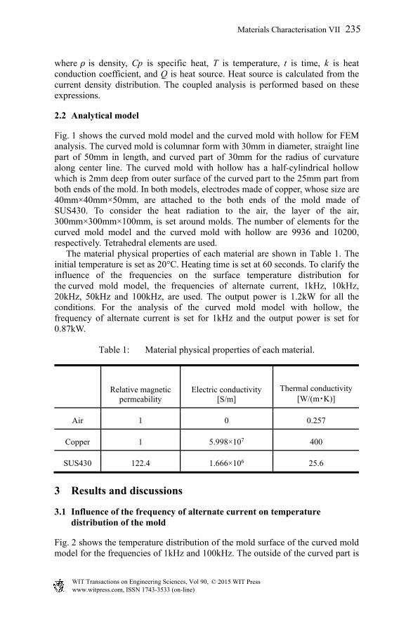
Fig. 2 shows the temperature distribution of the mold surface of the curved mold model for the frequencies of 1kHz and 100kHz. The outside of the curved part is
WIT Transactions on Engineering Sciences, Vol 90, www.witpress.com, ISSN 1743-3533 (on-line)
© 2015 WIT Press
Materials Characterisation VII 235

Figure 1: Curved mold model and curved mold with hollow model.
(i) FEM model (ii) Cross-sectional view
(a) Curved mold model
(i) FEM model (ii) Cross-sectional view
(b) Curved mold with hollow model
WIT Transactions on Engineering Sciences, Vol 90, www.witpress.com, ISSN 1743-3533 (on-line)
© 2015 WIT Press
236 Materials Characterisation VII
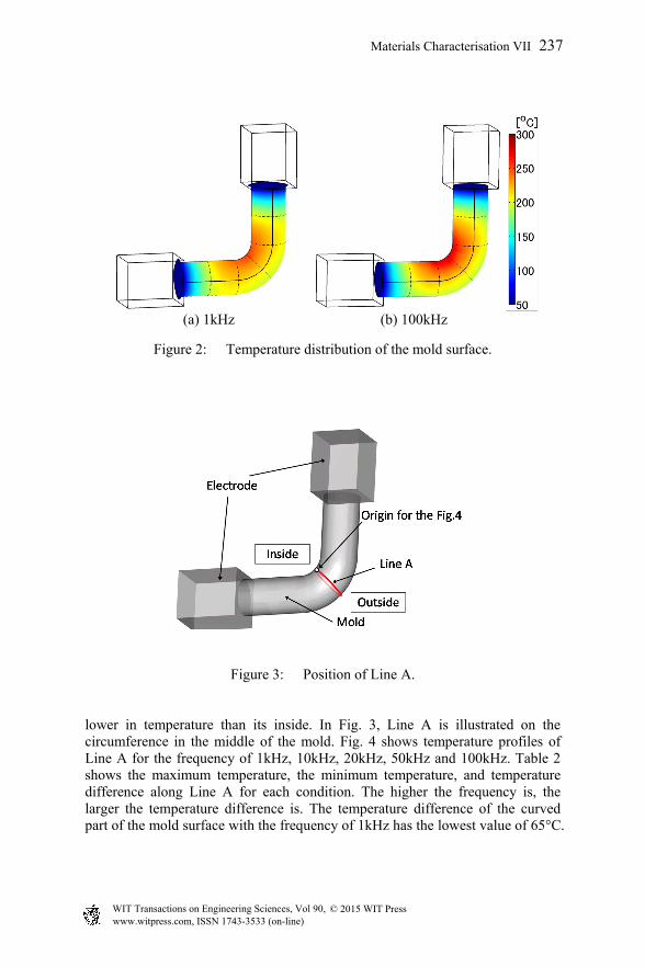
Figure 2: Temperature distribution of the mold surface.
Figure 3: Position of Line A.
lower in temperature than its inside. In Fig. 3, Line A is illustrated on the circumference in the middle of the mold. Fig. 4 shows temperature profiles of Line A for the frequency of 1kHz, 10kHz, 20kHz, 50kHz and 100kHz. Table 2 shows the maximum temperature, the minimum temperature, and temperature difference along Line A for each condition. The higher the frequency is, the larger the temperature difference is. The temperature difference of the curved part of the mold surface with the frequency of 1kHz has the lowest value of 65°C.
(a) 1kHz (b) 100kHz
WIT Transactions on Engineering Sciences, Vol 90, www.witpress.com, ISSN 1743-3533 (on-line)
© 2015 WIT Press
Materials Characterisation VII 237

Figure 4: Temperature profiles of Line A.
Table 2: The maximum, minimum temperature and temperature difference for profiles of Line A.
Frequency Maximum temperature [°C]
Minimum temperature [°C]
Temperature difference[°C]
100kHz 282 183 99
50kHz 279 184 95
20kHz 271 184 87
10kHz 273 194 79
1kHz 254 189 65
3.2 Influence of hollowing-out of the mold on temperature distribution
Fig. 5 shows the temperature distribution of the surface of the curved mold with hollow model with the frequency of 1kHz. Fig. 6 shows temperature profiles along Line A on the curved mold model and curved mold with hollow model. Fig. 7 shows temperature distribution of cross section along Line A for each model. The temperature of the outside of the curved part of the curved mold with hollow model is higher than that of the curved mold model. While the temperature difference along Line A for the curved mold model is 65°C in Fig. 6, that of the curved mold with hollow model has smaller temperature difference of 17°C.
WIT Transactions on Engineering Sciences, Vol 90, www.witpress.com, ISSN 1743-3533 (on-line)
© 2015 WIT Press
238 Materials Characterisation VII

Figure 5: Temperature distribution of the surface of curved mold with hollow model.
Figure 6: Temperature profiles along Line A.
Figure 7: Temperature distribution in the cross section along Line A.
Inside Inside
Outside Outside
(a) Curved mold model (b) Curved mold with hollow model
WIT Transactions on Engineering Sciences, Vol 90, www.witpress.com, ISSN 1743-3533 (on-line)
© 2015 WIT Press
Materials Characterisation VII 239

Fig. 8 shows current density distribution in cross section along Line A for each model. For both models, current density distribution is high at the inside and low at the outside. In spite of hollow structure, current density of the curved mold with hollow model is similar to that of the curved mold model. Skin depth as σ is expressed in equation (6):
σ (6)
where F is frequency, ρ is relative permittivity, μ is relative magnetic permeability. Because skin depth is related these value, mold shape doesn’t affect the skin depth. So current density distribution of both models is similarly.
Figure 8: Current density distribution in the cross section along Line A.
Fig. 9 shows heat flux distribution in cross section along Line A for each model. In the cross section of the mold, heat is transferred from heated surface part to the center. For the curved mold with hollow model, Point A in Fig. 9 which is high heat flux has low temperature in Fig. 6. This results means that the heat flux play an important rule for the temperature distribution of the surface of the mold. In Fig. 9, heat flux of outside of the curved mold with hollow model is lower than that of the curved mold model. Because of this low heat flux, the temperature at the outside of the curved mold with hollow model became high. By hollowing out the mold, it is possible to suppress the heat flux at the outside of the curved part and resulting the uniform temperature distribution.
4 Conclusions
In this study, to reveal the temperature distribution of the curved mold and to obtain uniform temperature distribution of the curved mold, the influence of the frequency of alternating current on the curved mold is analyzed by using FEM
Inside Inside
Outside Outside
(a) Curved mold model (b) Curved mold with hollow model
WIT Transactions on Engineering Sciences, Vol 90, www.witpress.com, ISSN 1743-3533 (on-line)
© 2015 WIT Press
240 Materials Characterisation VII

Figure 9: Heat flux distribution in the cross section along Line A.
analysis and the novel mold structure with hollow is proposed. The investigation yields the following conclusions:
1. For the curved mold model, the temperature difference of the mold surfacebecome larger when the frequency become higher. The temperature differenceof the mold surface with the frequency of 1kHz has the lowest value of 65°C.
2. By hollowing out the mold, it is possible to suppress the heat flux on theoutside of the curved part and resulting the uniform temperature distribution.
Inside Inside
Outside Outside
(i) Curved mold model (ii) Curved mold with hollow model
(a) Value of heat flux
Inside Inside
Outside Outside
(i) Curved mold model (ii) Curved mold with hollow model
(b) Direction of heat flux
WIT Transactions on Engineering Sciences, Vol 90, www.witpress.com, ISSN 1743-3533 (on-line)
© 2015 WIT Press
Materials Characterisation VII 241
References
[1] Automobile Survey “Composites in Automotive: How far are composites materials from mass production?”, Editor: M. Vesco, JEC composites, 2011.
[2] S. Toyoda, K. Suzuki & A. Sato, High strength steel tubes for automotive suspension parts -high strength steel tubes with excellent formability and forming technology for light weight automobiles-, JFE Giho, No. 4, pp. 28-32, 2004.
[3] Y. Maki, Current status and future trend of automotive ferrous materials, Journal of electric furnace steel, Vol. 70, No. 1, pp. 5-15, 1999.
[4] E. Wadahara & A. Kitano, Automotive lightweight structural elements of carbon fiber reinforced plastics, Sen’i Gakkaishi, Vol. 64, No. 9, pp. 295-301, 2008.
[5] K. Tanaka, N. Kohashi, Y. Kinoshita, T. Katayama & K. Uno, Compression molding of carbon fiber reinforced thermoplastics using non-woven stitched multi-axial cloth by means of induction heating system, Journal of the Society of Materials Science, Japan, Vol. 58, No. 7, pp. 642-648, 2009.
[6] K. Tanaka, R. Harada, T. Uemura, T. Katayama & H. Kuwahara, Rapid pipe moulding process of carbon fibre reinforced thermoplastics by high-frequency direct resistance heating, WIT Transactions on the Built Environment, Vol. 112, pp. 133-139, 2010.
[7] K. Tanaka, Y. Matsuura, R. Harada, T. Katayama, & S. Enoki, FEM analysis of temperature distribution of CFRTP pipe mold with direct resistance heating, WIT Transactions on the Built Environment, Vol. 137, pp. 265-272, 2014.
[8] H. Ueda & A. Ishiyama, Numerical electromagnetic analysis for applied superconductivity I -basics of numerical electromagnetic analysis-, Teion Kogaku, Vol. 47, No.11, pp. 623-632, 2012.
WIT Transactions on Engineering Sciences, Vol 90, www.witpress.com, ISSN 1743-3533 (on-line)
© 2015 WIT Press
242 Materials Characterisation VII