feed - cache.industry.siemens.com · legal information legal information warning notice system this...
TRANSCRIPT
� �FEED
____________________________________________________________________________________________________________________________________________________________________________________________________________________________________________________________________________________________________________________________________________________________________________________________
COMOS
Process FEED
Operating Manual
08/2011 A5E03640188-01
Trademarks 1
Introduction 2
Project structure 3
Example project 4
Overview of workflow variants
5
Creating components 6
Editing a block diagram 7
Simulation import 8
Working in the PF 9
Specifying equipment 10
Case-specific data 11
Data flow 12
Evaluating reports 13
PF and P&ID report 14
Managing cases 15
Cost estimation 16
Knowledge base 17
Administration 18
Base data reference 19
User interface reference 20
Legal information
Legal information Warning notice system
This manual contains notices you have to observe in order to ensure your personal safety, as well as to prevent damage to property. The notices referring to your personal safety are highlighted in the manual by a safety alert symbol, notices referring only to property damage have no safety alert symbol. These notices shown below are graded according to the degree of danger.
DANGER indicates that death or severe personal injury will result if proper precautions are not taken.
WARNING indicates that death or severe personal injury may result if proper precautions are not taken.
CAUTION with a safety alert symbol, indicates that minor personal injury can result if proper precautions are not taken.
CAUTION without a safety alert symbol, indicates that property damage can result if proper precautions are not taken.
NOTICE indicates that an unintended result or situation can occur if the relevant information is not taken into account.
If more than one degree of danger is present, the warning notice representing the highest degree of danger will be used. A notice warning of injury to persons with a safety alert symbol may also include a warning relating to property damage.
Qualified Personnel The product/system described in this documentation may be operated only by personnel qualified for the specific task in accordance with the relevant documentation, in particular its warning notices and safety instructions. Qualified personnel are those who, based on their training and experience, are capable of identifying risks and avoiding potential hazards when working with these products/systems.
Proper use of Siemens products Note the following:
WARNING Siemens products may only be used for the applications described in the catalog and in the relevant technical documentation. If products and components from other manufacturers are used, these must be recommended or approved by Siemens. Proper transport, storage, installation, assembly, commissioning, operation and maintenance are required to ensure that the products operate safely and without any problems. The permissible ambient conditions must be complied with. The information in the relevant documentation must be observed.
Trademarks All names identified by ® are registered trademarks of Siemens AG. The remaining trademarks in this publication may be trademarks whose use by third parties for their own purposes could violate the rights of the owner.
Disclaimer of Liability We have reviewed the contents of this publication to ensure consistency with the hardware and software described. Since variance cannot be precluded entirely, we cannot guarantee full consistency. However, the information in this publication is reviewed regularly and any necessary corrections are included in subsequent editions.
Siemens AG Industry Sector Postfach 48 48 90026 NÜRNBERG GERMANY
A5E03640188-01 Ⓟ 09/2011
Copyright © Siemens AG 2011. Technical data subject to change

FEED Operating Manual, 08/2011, A5E03640188-01 3
Table of contents
1 Trademarks ............................................................................................................................................... 9
2 Introduction.............................................................................................................................................. 11
3 Project structure ...................................................................................................................................... 13
3.1 Creating an engineering project...................................................................................................13
3.2 Creating a process with a block diagram.....................................................................................13
4 Example project ....................................................................................................................................... 17
5 Overview of workflow variants ................................................................................................................. 19
6 Creating components............................................................................................................................... 23
7 Editing a block diagram ........................................................................................................................... 25
7.1 Basic functions of a block diagram ..............................................................................................25
7.2 Creating and specifying process units .........................................................................................25
7.3 Contents of the "APU Process units" folder.................................................................................27
7.4 Creating a process unit manually.................................................................................................28
7.5 Using material input arrows and material output arrows .............................................................28
7.6 Using boundary streams ..............................................................................................................29
7.7 Using boundary stream flags .......................................................................................................31
8 Simulation import ..................................................................................................................................... 33
8.1 Basic principles ............................................................................................................................33 8.1.1 Definition of interfaces .................................................................................................................33 8.1.2 Structure for import below process unit or process .....................................................................33 8.1.3 General import workflow ..............................................................................................................35 8.1.4 Starting point for the import..........................................................................................................36
8.2 AspenTech Aspen Plus and Bryan Research & Engineering ProMax import .............................37 8.2.1 Options for XML nodes in the AspenTech Aspen Plus simulator ................................................37 8.2.2 Creating an import object with a link............................................................................................38 8.2.3 Configuring an import object ........................................................................................................38 8.2.4 Import step 1: Start import ...........................................................................................................40 8.2.4.1 Introduction ..................................................................................................................................40 8.2.4.2 Complete import...........................................................................................................................40 8.2.4.3 Partial import ................................................................................................................................41 8.2.5 Import step 2: Create PF objects .................................................................................................42 8.2.6 Import step 3: Place PF streams on the PF.................................................................................45 8.2.7 Importing additional cases ...........................................................................................................46
8.3 Import from Chemstations ChemCad, Evonik EbsilonProfessional, AspenTech HYSYS, Invensys PRO/II, Honeywell UniSim Design ...............................................................................47
8.3.1 Creating an import document.......................................................................................................47 8.3.2 Configuring an import document..................................................................................................48

Table of contents
FEED 4 Operating Manual, 08/2011, A5E03640188-01
8.3.3 Import step 1: Start import........................................................................................................... 48 8.3.3.1 Complete import.......................................................................................................................... 48 8.3.3.2 Partial import ............................................................................................................................... 49 8.3.4 Import step 2: Create PF objects ................................................................................................ 49 8.3.5 Import step 3: Place the equipment on the PF............................................................................ 50 8.3.6 Import step 4: Place PF streams on the PF................................................................................ 51 8.3.7 Invensys PRO/II: Behavior during reimporting............................................................................ 52
8.4 Wildcard objects.......................................................................................................................... 52 8.4.1 Basic principles ........................................................................................................................... 52 8.4.2 Importing wildcard objects........................................................................................................... 53
8.5 Log files for simulator import ....................................................................................................... 55
8.6 Folder for SIM objects ................................................................................................................. 56
8.7 Batch import of simulation files ................................................................................................... 56 8.7.1 Basic principles ........................................................................................................................... 56 8.7.2 Creating "Batch Import Control Center" ...................................................................................... 56 8.7.3 Using "Batch Import Control Center" .......................................................................................... 57
9 Working in the PF .................................................................................................................................... 61
9.1 Basic principles ........................................................................................................................... 61
9.2 Operation..................................................................................................................................... 61
9.3 Manual placing and editing of PF objects ................................................................................... 61 9.3.1 Placing equipment manually ....................................................................................................... 61 9.3.2 Placing objects from the report bar ............................................................................................. 62 9.3.3 Editing objects via the report bar ................................................................................................ 63 9.3.4 Using the navigator to place objects ........................................................................................... 64 9.3.5 Editing objects via the properties ................................................................................................ 64
9.4 Working with process streams .................................................................................................... 65 9.4.1 The "Connection" tool ................................................................................................................. 65 9.4.2 Using the "Connection" tool to create process streams.............................................................. 66 9.4.3 Creating and placing process streams from the Navigator......................................................... 66 9.4.4 Editing process streams on the PFD .......................................................................................... 67 9.4.5 Properties of the process streams .............................................................................................. 67
9.5 Other placeable objects .............................................................................................................. 68 9.5.1 Overview ..................................................................................................................................... 68 9.5.2 Placing process stream flags ...................................................................................................... 69 9.5.3 Using pipe breaks ....................................................................................................................... 69 9.5.4 Creating page references............................................................................................................ 70
9.6 Configuring mass balances......................................................................................................... 72
9.7 Grouping components................................................................................................................. 75
9.8 Adding an equipment list to the PF ............................................................................................. 76
10 Specifying equipment .............................................................................................................................. 79
10.1 General properties ...................................................................................................................... 79 10.1.1 Determining the main equipment for a process unit ................................................................... 79 10.1.2 Evaluating reports for the equipment .......................................................................................... 79 10.1.3 Graphical display......................................................................................................................... 79

Table of contents
FEED Operating Manual, 08/2011, A5E03640188-01 5
10.1.4 Maximum and minimum design pressure and maximum and minimum design temperature..................................................................................................................................80
10.2 Calculating pump attributes in MS Excel .....................................................................................80
10.3 Tray mapping ...............................................................................................................................81
10.4 Assigning a different base object .................................................................................................81
10.5 HTRI import/export.......................................................................................................................82
11 Case-specific data ................................................................................................................................... 85
11.1 Basic principles ............................................................................................................................85
11.2 Creating case-specific objects .....................................................................................................85
11.3 Standard cases ............................................................................................................................85
11.4 Material streams ..........................................................................................................................85 11.4.1 Basic principles ............................................................................................................................85 11.4.2 Editing material streams ..............................................................................................................86 11.4.3 Determining the active material stream .......................................................................................87 11.4.4 Using material streams with identical values ...............................................................................87 11.4.5 Determining the components of a material stream......................................................................89
11.5 Components.................................................................................................................................89 11.5.1 Basic principles ............................................................................................................................89 11.5.2 Editing components .....................................................................................................................90 11.5.3 Automatic attribute calculation.....................................................................................................91
11.6 Equipment cases (ECs) ...............................................................................................................91 11.6.1 Basic principles ............................................................................................................................91 11.6.2 Editing equipment cases..............................................................................................................91 11.6.3 Determining the active equipment case.......................................................................................92
12 Data flow.................................................................................................................................................. 93
12.1 Overview ......................................................................................................................................93
12.2 Data exchange between boundary stream and assigned process stream..................................93
12.3 Data flow between a process stream and its material streams ...................................................94
12.4 Data flow between the components and their material stream....................................................95
12.5 Data flow between the equipment and its equipment cases .......................................................96
12.6 Data flow from process stream to the connected equipment ......................................................97
13 Evaluating reports.................................................................................................................................... 99
13.1 Evaluating reports under the process ..........................................................................................99
13.2 Evaluating reports of the "ABS boundary streams" folder .........................................................100
13.3 Evaluating reports in the "AMA components" folder ..................................................................101
13.4 Evaluating reports under the process units ...............................................................................101
13.5 Evaluating reports under the equipment....................................................................................103

Table of contents
FEED 6 Operating Manual, 08/2011, A5E03640188-01
14 PF and P&ID report ............................................................................................................................... 105
14.1 Converting a PF into a P&ID..................................................................................................... 105
14.2 Using P&ID default templates ................................................................................................... 107
14.3 Selecting your own P&ID template ........................................................................................... 108
14.4 Creating multiple P&IDs from a PF ........................................................................................... 110
14.5 Data flow between PF objects and P&ID objects ..................................................................... 110
15 Managing cases..................................................................................................................................... 111
15.1 Basic principles ......................................................................................................................... 111
15.2 "Case manager" user interface reference tab:.......................................................................... 111
16 Cost estimation...................................................................................................................................... 115
16.1 Purpose..................................................................................................................................... 115
16.2 Calculation basis for cost estimation......................................................................................... 115
16.3 Cost basis object....................................................................................................................... 115
16.4 Cost object ................................................................................................................................ 116
16.5 Offer basis object ...................................................................................................................... 117
17 Knowledge base .................................................................................................................................... 119
17.1 Basic principles ......................................................................................................................... 119
17.2 Creating the knowledge base, status display............................................................................ 119
17.3 Checking a process................................................................................................................... 120
18 Administration........................................................................................................................................ 123
18.1 Mapping of units between AspenTech Aspen Plus or Bryan Research & Engineering ProMax and COMOS ................................................................................................................ 123
18.2 Using the knowledge base rule editor....................................................................................... 124
18.3 Modifying the standard import................................................................................................... 124 18.3.1 Überblick ................................................................................................................................... 124 18.3.2 Import objects: Buttons ............................................................................................................. 125 18.3.3 Simulation objects ..................................................................................................................... 126 18.3.3.1 Überblick ................................................................................................................................... 126 18.3.3.2 Import()...................................................................................................................................... 128 18.3.3.3 ImportDone() ............................................................................................................................. 129 18.3.3.4 SimulatorImport() ...................................................................................................................... 130 18.3.3.5 SimulatorImportDone().............................................................................................................. 130 18.3.4 AspenTech Aspen Plus: Class AspenNode.............................................................................. 130 18.3.4.1 Properties.................................................................................................................................. 131 18.3.4.2 Read() ....................................................................................................................................... 132 18.3.4.3 ReadArray()............................................................................................................................... 135 18.3.4.4 CreateSubObjects() .................................................................................................................. 136 18.3.4.5 XML ValueExist() ...................................................................................................................... 137 18.3.5 Bryan Research & Engineering ProMax ................................................................................... 138 18.3.5.1 Public class ProMaxNode ......................................................................................................... 139 18.3.5.2 Public class BlockNode: ProMaxNode...................................................................................... 140

Table of contents
FEED Operating Manual, 08/2011, A5E03640188-01 7
18.3.5.3 Public class StreamNode: ProMaxNode....................................................................................141 18.3.5.4 Public class ComponentNode: StreamNode .............................................................................142 18.3.6 Invensys PRO/II:Class ProIINode..............................................................................................143 18.3.6.1 Properties...................................................................................................................................143 18.3.6.2 Read() ........................................................................................................................................144 18.3.6.3 ReadArray()................................................................................................................................145 18.3.6.4 ReadArrayToFewSpecs() ..........................................................................................................146 18.3.6.5 ReadSI().....................................................................................................................................146 18.3.6.6 GetComosSpecArray()...............................................................................................................147 18.3.6.7 Intern verwendete Funktionen ...................................................................................................147 18.3.7 AspenTech HYSYS: Class HYSYSNode...................................................................................148 18.3.7.1 Properties...................................................................................................................................149 18.3.7.2 HYSYSClass()............................................................................................................................150 18.3.7.3 LiquidPhase1() ...........................................................................................................................150 18.3.7.4 LiquidPhase2() ...........................................................................................................................150 18.3.7.5 Read() ........................................................................................................................................150 18.3.7.6 ReadPhase ................................................................................................................................151 18.3.7.7 VapourPhase() ...........................................................................................................................151 18.3.8 Honeywell UniSim Design: Class UniSimNode .........................................................................151 18.3.9 Evonik EbsilonProfessional: Class EbsilonNode.......................................................................151 18.3.9.1 Properties...................................................................................................................................152 18.3.9.2 GetEbsKind()..............................................................................................................................152 18.3.9.3 Read() ........................................................................................................................................152 18.3.9.4 ReadNumeric()...........................................................................................................................153 18.3.10 Chemstations ChemCad: Class ChemCad Node......................................................................153 18.3.10.1 Properties..............................................................................................................................154 18.3.10.2 GetChemCadClass().............................................................................................................154 18.3.10.3 ReadNumeric()......................................................................................................................154 18.3.10.4 ReadEquilibriumReactionPar() .............................................................................................155 18.3.10.5 ReadStreamComponents .....................................................................................................155 18.3.10.6 FillTrayStreamList .................................................................................................................155 18.3.11 Default settings for the simultaneous import of multiple files.....................................................156 18.3.12 Setting margins for automatic placing of equipment on reports ................................................156 18.3.13 Settings for importing unknown simulation objects....................................................................157
18.4 Assemblies.................................................................................................................................158 18.4.1 Allgemeines zu Baugruppen......................................................................................................158 18.4.2 Creating P&ID assemblies .........................................................................................................159 18.4.2.1 Creating the unit as a collection folder for P&ID objects ...........................................................159 18.4.2.2 Verknüpfen der DimLen- und PFD-Objekte...............................................................................159 18.4.2.3 Connector mapping....................................................................................................................160 18.4.2.4 R&I-Baugruppen erstellen..........................................................................................................160 18.4.3 Availability of P&ID assemblies..................................................................................................161 18.4.4 Baugruppen aus Baugruppen erstellen .....................................................................................161 18.4.5 The PE Base object structure ....................................................................................................162 18.4.5.1 PE-Hauptknoten.........................................................................................................................162 18.4.5.2 "DS Data Structure" ...................................................................................................................162 18.4.5.3 "PO Process Objects" ................................................................................................................163 18.4.5.4 "US Unit System" .......................................................................................................................163 18.4.6 Tips for administrators on PE objects ........................................................................................164 18.4.6.1 Tipps für Verfahrenseinheiten....................................................................................................164 18.4.6.2 Tipps für Bilanzströme ...............................................................................................................164 18.4.6.3 Verknüpfungen von Equipment-Attributen kontrollieren ............................................................164

Table of contents
FEED 8 Operating Manual, 08/2011, A5E03640188-01
19 Base data reference .............................................................................................................................. 165
19.1 "@1PE > PO > SIM Simulation Objects" .................................................................................. 165 19.1.1 Eigenschaften der Simulationsobjekte...................................................................................... 166 19.1.2 "@1PE > PO > SIM > BLC Equipment Simulation Objects"..................................................... 168 19.1.3 "@1PE > PO > SIM > STR Stream Simulation Objects" .......................................................... 170 19.1.3.1 "@1PE > PO > SIM > STR > CCSIM CompCalc Simulation Object" ....................................... 170 19.1.3.2 "@1PE > PO > SIM > STR > MSSIM Material Stream Simulation Object" .............................. 170 19.1.4 "@1PE > PO > SIM > SUB Simulation Subobjects" ................................................................. 171 19.1.4.1 "@1PE > PO > SIM > SUB > HCSIM Heating Curve Simulation Object" ................................ 171 19.1.4.2 "@1PE > PO > SIM > SUB > LHCSIM LNG Cells Simulation Object" ..................................... 172 19.1.4.3 "@1PE > PO > SIM > SUB > MAPSIM Component Simulation Object" .................................. 172 19.1.4.4 "@1PE > PO > SIM > SUB > TRSIM Column Tray Simulation Object" ................................... 173 19.1.5 "@1PE > PO > SIM > XXSI Simulation Import Objects"........................................................... 173 19.1.5.1 "@1PE > PO > SIM > XXSI > AXSI Aspen XML-Simulation Import" ....................................... 173 19.1.5.2 "@1PE > PO > SIM > XXSI > AXSI1 Aspen XML Simulations Import (Case)" ........................ 175 19.1.5.3 "@1PE > PO > SIM > XXSI > SIMCASE Simulation Case" ..................................................... 176
19.2 PFD objects............................................................................................................................... 176 19.2.1 "@1PE > PO > EQ Equipment" ................................................................................................ 176 19.2.1.1 Eigenschaften allgemein........................................................................................................... 176 19.2.1.2 "@1PE > PO > EQ > 02 > COL Column" ................................................................................. 177 19.2.1.3 "@1PE > PO > EQ > 04 > HEX Heat Exchanger".................................................................... 178 19.2.1.4 "@1PE > PO > EQ > 04 > LNG Heat Exchanger".................................................................... 178 19.2.1.5 "@1PE > PO > EQ > 04 > CELL LNG Heat Exchanger Cell"................................................... 179 19.2.1.6 "@1PE > PO > EQ > 08 > CCS > TRA Tray Layout (General)"............................................... 179 19.2.1.7 "@1PE > PO > EQ > 08 > COS Column Section".................................................................... 179 19.2.2 "@1PE > PO > EC Equipment Cases" ..................................................................................... 179 19.2.2.1 Eigenschaften allgemein........................................................................................................... 180 19.2.2.2 "@1PE > PO > EC > 02 > COLEC Column"............................................................................. 180 19.2.2.3 "@1PE > PO > EC > 08 > CCS > TRAEC Tray Layout (General)" .......................................... 180 19.2.3 "@1PE > PO > SO > MAP Component Reference" ................................................................. 180 19.2.4 "@1PE > PO > SO > MAS Pure Components" ........................................................................ 182 19.2.5 "@1PE > PO > SO > MS Case"................................................................................................ 182 19.2.6 "@1PE > PO > SO > PS Process Stream"............................................................................... 183
19.3 "@1PE > DS Data Structures" .................................................................................................. 185 19.3.1 "@1PE > DS > @O Documents" .............................................................................................. 185 19.3.1.1 "@1PE > DS > @O Documents > PRZ ProII Simulation Import" ............................................. 185 19.3.1.2 "@1PE > DS > @O Documents > HYSYS HYSYS Simulation Import" ................................... 187 19.3.2 "@1PE > DS > @Y Attributes Catalog" .................................................................................... 188 19.3.3 "@1PE > DS > CC Tabs Catalog" ............................................................................................ 188
19.4 Auswahllisten ............................................................................................................................ 188
19.5 Creating and grouping pure components under the "AMA" folder............................................ 189
19.6 Object classes used .................................................................................................................. 189
20 User interface reference ........................................................................................................................ 191
20.1 "Import options" tab................................................................................................................... 191
20.2 "Partial import" window ............................................................................................................. 192
Glossary ................................................................................................................................................ 193

FEED Operating Manual, 08/2011, A5E03640188-01 9
Trademarks 1Trademarks
Registered trademark: COMOS®

Trademarks
FEED 10 Operating Manual, 08/2011, A5E03640188-01

FEED Operating Manual, 08/2011, A5E03640188-01 11
Introduction 2Aim
COMOS FEED is used in the initial phase of plant engineering. Its scope of functions covers all areas of process engineering:
● General modeling of the process in the block diagram
● Specific description of process units and their equipment in a process flow diagram (PFD)
● Management of case-specific process data
● Component management
● Automatic documentation of engineering in the form of mass balances, equipment lists and data sheets
● Seamless transfer of process engineering to P&ID engineering
Functions ● Import of any cases from the simulation programs AspenTech AspenPlus, Bryan
Research & Engineering, Inc. ProMax, Invensys Operations Management PRO/II, AspenTech HYSYS, Chemstations Inc. ChemCad, Evonik Energy Services GmbH EbsilonProfessional and Honeywell Process Solutions UniSim Design
● User-friendly case management
● Automatic data exchange between PFD objects and their case-specific objects
● Configuration of the process stream list, equipment list and material balance on PFs
● Technical data for calculating mechanical data for designing pumps in Excel sheets
● Automatic conversion of a PFD into a P&ID
● Assignment between the theoretical levels of a column and its trays
● Status check according to predefined rules (engineering rules) in the knowledge base

Introduction
FEED 12 Operating Manual, 08/2011, A5E03640188-01

FEED Operating Manual, 08/2011, A5E03640188-01 13
Project structure 33.1 Creating an engineering project
Requirements You have the necessary rights for creating an engineering project
Procedure 1. Start COMOS.
2. Select the "File > Open project" command in the menu bar.
3. In the "Open project" tab, select the "Engineering" option.
4. To open the shortcut menu, right-click in the table area.
5. Select the "New > Project" command in the shortcut menu.
The new project is created and the project properties open.
6. Enter a "Name" and a "Description" for the project in the "General" tab.
By default, the "Type" of the project matches the option selected on the "Open project" tab.
7. Switch to the "Links" tab.
8. Click the "..." button next to "Project structure".
The "Select project structure for <project name>" window opens.
9. Select the "@J > @PE FEED structure" node.
10. Confirm your selection with "OK".
Result You have now created a new engineering project that you can select from the list of available projects.
3.2 Creating a process with a block diagram In COMOS, the chemical process that you model is encapsulated in a "Process" object. All the work you carry out is conducted underneath this object.

Project structure 3.2 Creating a process with a block diagram
FEED 14 Operating Manual, 08/2011, A5E03640188-01
Procedure 1. Right-click the project root.
2. Select "New > PR Process" in the shortcut menu.
Result ● A new process is created underneath the project root.
● On the basis of the project structure specifications, the following documents/document groups and folders are automatically created underneath the process:
Object Description "PFB.1 Block Diagram DIN A4 x A1" interactive report
The block diagram in which the process is described.
"PFB.3 Equipment list, total", "PFB.4 Equipment lists", "PFB.5 Mass balances" document groups
Multiple document groups under which the equipment lists and mass balances of the process are collected.
"ABSBoundary streams" folder A folder in which the boundary streams for the process are collected.
"AMAComponents" folder A folder in which the components for the process are collected.
"APUProcess units" folder A folder in which the process units for the process are collected.
In the shortcut menu for the process, the "New" command offers additional folders, documents, and document groups. In most cases, you will only require these if you are carrying out a simulation for the entire process, rather than at process unit level.

Project structure 3.2 Creating a process with a block diagram
FEED Operating Manual, 08/2011, A5E03640188-01 15
Properties of the process You can use the properties window to more precisely configure the settings for the process.
The following configuration options are available:
● "Case Manager" tab:
Here you have the option of managing cases at process level.
You will use option this later, as your process is currently still empty. For this reason, case management is covered in a different section of this documentation. See also Section Managing cases (Page 111).
● "Material balance" tab
Here you have the option of defining the following for the entire process:
– Which components are output on the mass balances?
– In what order are the components output?
– Are the components grouped?
You will use option this later, as your process is currently still empty. For this reason, the grouping of components is covered in a different section of this documentation. See also Section Grouping components (Page 75).

Project structure 3.2 Creating a process with a block diagram
FEED 16 Operating Manual, 08/2011, A5E03640188-01

FEED Operating Manual, 08/2011, A5E03640188-01 17
Example project 4
An example project is included in the COMOS FEED scope of supply. The descriptions in the following sections are based on this sample project.
Calling the example project To call the example project, proceed as follows:
1. Select the "File > Open project" command in the menu bar.
The "Open project" tab opens and shows a list of the available engineering projects.
2. Open the "COMOS_FEED" project.
3. Switch to the "Units" tab in the Navigator.
4. Open the "PR001 Process" node.

Example project
FEED 18 Operating Manual, 08/2011, A5E03640188-01

FEED Operating Manual, 08/2011, A5E03640188-01 19
Overview of workflow variants 5Overview of workflow variants
Several workflow variants are available in the FEED module. The variant you select depends on the following points:
1. Are you using a block diagram for process engineering purposes?
2. Is your PF based on a simulation imported to COMOS?
The manual assumes that a block diagram is being used and that the PF is based on a simulation.
Variant 1: With block diagram and simulation import Step Description 1 Create a process 2 Create the components required for the process 3 Describe the process in general terms on a block diagram 4 Assign the components of the "AMA Components" folder to the material input arrows and
material output arrows of the block diagram For each process unit: 5 Outside of COMOS:
Create a simulation of the process unit in a simulation software 6 Create a PF 7 Carry out steps 1 and 2 of the simulation import; i.e. import the case-specific process data
from the simulation software in question Result: The relevant PF objects and their case-specific data are automatically created in
COMOS and sorted into the "AEQ Equipment", "APS Process streams", and "AXX Miscellaneous" folders below the process unit in the Navigator
If necessary, any missing components are imported to the "AMA" folder
8 Carry out simulation import steps 3 and 4 (in the case of Aspen, step 3 only); i.e. have the PF objects placed on the PF of the process unit automatically
9 Carry out the finishing touches on the PF: Carry out graphical adjustments (moving objects, adjusting the path of the process
stream, etc.) Place process stream flags on the PF for the purpose of outputting stream-related data Place any other required objects (for example, functions, pipe breaks, plant limits, flow
direction arrows, etc.)
10 Specify the properties of the equipment

Overview of workflow variants
FEED 20 Operating Manual, 08/2011, A5E03640188-01
Step Description 11 Miscellaneous:
Assign a piece of main equipment to each process unit If required: Assign a boundary stream from the PF to each process stream
12 If required: Import additional cases, reimport a case, etc. (Case Manager)
13 Documentation and evaluation of the engineering by means of automatic generation of various evaluation reports (lists and data sheets): The following data sheets and lists are available to use while working with FEED; these are created automatically and synchronized with the engineering data: Processes: Mass balances, equipment lists Boundary streams: Boundary stream list Components: Component lists Process units: Mass balances, equipment lists Equipment: Technical data sheets, process data sheets
14 Transition to P&ID engineering phase: Convert PFs to P&IDs
Variant 2: With block diagram and without simulation import Step Description 1 to 4 As variant 1, steps 1 to 4 For each process unit: 2 Create PF manually 3 Create the required cases in the Run Case Manager and enter the case-specific data
manually 4 and 5 As variant 1, steps 10 and 11 6 and 7 As variant 1, steps 13 and 14
Variant 3: Without block diagram and with simulation import Step 1 Create a process 2 Create the required process units underneath the process For each process unit: 3 to 12 As variant 1, steps 5 to 14

Overview of workflow variants
FEED Operating Manual, 08/2011, A5E03640188-01 21
Variant 4: Without block diagram and without simulation import Step Description 1 Create a process 2 Create the components required for the process 3 Create the required process units underneath the process For each process unit: 4 Create PF manually 5 Create the required cases in the Run Case Manager and enter the case-specific data
manually 6 and 7 As variant 1, steps 10 and 11 8 and 9 As variant 1, steps 13 and 14

Overview of workflow variants
FEED 22 Operating Manual, 08/2011, A5E03640188-01
FEED Operating Manual, 08/2011, A5E03640188-01 23
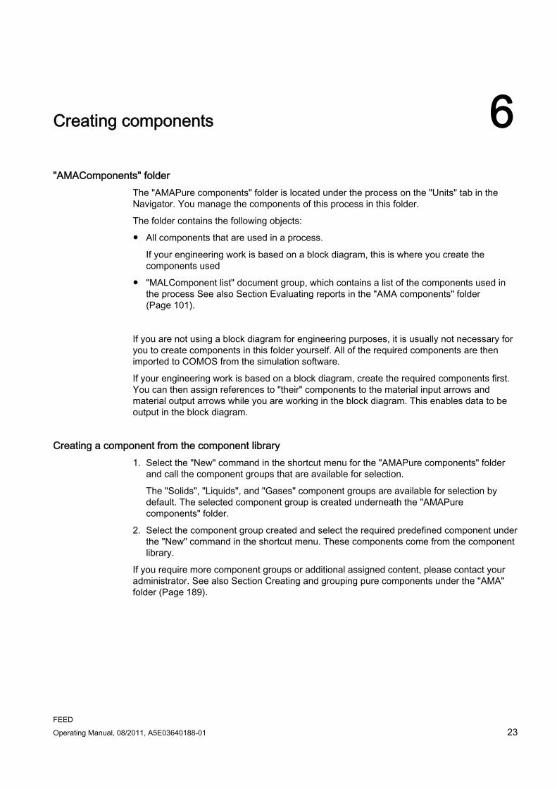
Creating components 6"AMAComponents" folder
The "AMAPure components" folder is located under the process on the "Units" tab in the Navigator. You manage the components of this process in this folder.
The folder contains the following objects:
● All components that are used in a process.
If your engineering work is based on a block diagram, this is where you create the components used
● "MALComponent list" document group, which contains a list of the components used in the process See also Section Evaluating reports in the "AMA components" folder (Page 101).
If you are not using a block diagram for engineering purposes, it is usually not necessary for you to create components in this folder yourself. All of the required components are then imported to COMOS from the simulation software.
If your engineering work is based on a block diagram, create the required components first. You can then assign references to "their" components to the material input arrows and material output arrows while you are working in the block diagram. This enables data to be output in the block diagram.
Creating a component from the component library 1. Select the "New" command in the shortcut menu for the "AMAPure components" folder
and call the component groups that are available for selection.
The "Solids", "Liquids", and "Gases" component groups are available for selection by default. The selected component group is created underneath the "AMAPure components" folder.
2. Select the component group created and select the required predefined component under the "New" command in the shortcut menu. These components come from the component library.
If you require more component groups or additional assigned content, please contact your administrator. See also Section Creating and grouping pure components under the "AMA" folder (Page 189).

Creating components
FEED 24 Operating Manual, 08/2011, A5E03640188-01
Creating a new component If the component you wish to use is not in the component library, create a new component:
1. In the shortcut menu of the "AMA" folder, select the "New > MA0000 Pure component" command.
A new component is created in the folder.
2. Open the properties of the new component and specify the attributes of the new component.

FEED Operating Manual, 08/2011, A5E03640188-01 25
Editing a block diagram 77.1 Basic functions of a block diagram
A block diagram (PF) is an interactive report. It is used to describe the process in general terms by means of process units, material input arrows and material output arrows, boundary streams, and boundary stream flags.
When you create a process, a block diagram is automatically created underneath it.
Block diagrams have the same basic functions as all other interactive reports.
Key basic functions 1. Placing objects from the symbol bar:
When you use the report symbol bar to place a symbol on the block diagram, a corresponding object is automatically created in the Navigator. In the FEED example project, the new object is sorted into one of the folders located on the same level as the block diagram.
2. Editing an object selected in the block diagram on the report bar:
When you select an object on the report, edit fields appear on the report bar. You can use these fields to edit important properties of the object directly from the report. Save your inputs by clicking the button containing the check mark at the right edge of the report bar.
If the bar is not big enough to show all the fields, you can make the fields appear by clicking the black arrow.
Additional information regarding the basic functions You can find additional information on this topic in the "Reports - Basic Operation" manual, under "Basic operation interactive report".
7.2 Creating and specifying process units Once you have opened the block diagram, you start your work on it by creating the process units and specifying them.
Editing a block diagram 7.2 Creating and specifying process units
FEED 26 Operating Manual, 08/2011, A5E03640188-01
Placing a process unit 1. Activate the "Process unit" button on the report bar:
2. Move the mouse to the required point in the report and left-click to place the process unit.
You can "stamp" as many process units as you wish onto the report, provided that the "Process unit" button is activated.
Result ● The process unit symbol is placed on the block diagram.
● A process unit is created in the Navigator and is automatically sorted into the "APUProcess units" folder under the process.
See also Section Contents of the "APU Process units" folder (Page 27).
Setting a description 1. Left-click to select the process unit on the report.
The "Name" and "Description" text fields appear on the report bar.
2. Enter the required description in the "Description" text field and confirm your input by using the button with the check mark.
The new description is output on the block diagram, in the uppermost text field of the process unit symbol.
Assigning main equipment You can assign a piece of main equipment to a process unit. The description for the assigned equipment is also output in the process unit symbol, but this time in the second text field from the top.
At this point in the engineering process, no equipment exists. How you proceed in order to assign a process unit to a piece of main equipment is, therefore, described later in this documentation. See also Section Determining the main equipment for a process unit (Page 79).

Editing a block diagram 7.3 Contents of the "APU Process units" folder
FEED Operating Manual, 08/2011, A5E03640188-01 27
Process unit symbol
7.3 Contents of the "APU Process units" folder The "APUProcess units" folder contains all process units drawn in on the block diagram.
On the basis of the project structures, the following documents/document groups and folders are automatically created underneath each process unit:
"MMB.1Mass balances", "PFB.1 Equipment Lists" document groups:
Two document groups underneath which the equipment lists and mass balances for the process unit are collected.
Process unit

Editing a block diagram 7.4 Creating a process unit manually
FEED 28 Operating Manual, 08/2011, A5E03640188-01
"PFD.1" interactive report The process diagram (PF) that describes the process unit in greater detail.
"AEQ Equipment", "APS Process streams","AXX Miscellaneous" folders
These folders are initially empty, but are automatically filled when you carry out a simulation import or draw new objects on the PF.
"SIMD Simulation data process unit" folder
You carry out the simulation imports in this folder.
See also Section Working in the PF (Page 61).
See also Section Simulation import (Page 33).
7.4 Creating a process unit manually If your engineering work is not based on a block diagram, you will need to create the process units manually.
Procedure 1. Select the "APU" folder.
2. Select the "New > PU Process unit" command in the shortcut menu.
Result A new process unit with the substructure described above is created in the folder.
Creating additional folders, documents, and document groups In the shortcut menu for the process unit, the "New" command offers additional folders, documents, and document groups. If you have any questions about one of these folders, documents, or document groups, please contact your administrator.
7.5 Using material input arrows and material output arrows In the next step, you define which materials are input or output for the process. For this, you use arrow symbols to which you assign references to components: material input arrows and material output arrows.

Editing a block diagram 7.6 Using boundary streams
FEED Operating Manual, 08/2011, A5E03640188-01 29
Placing material input arrows and material output arrows 1. On the report bar, activate the button for the material input and output arrows:
2. Left-click to stamp the required arrows onto the report.
In the Navigator, the corresponding database objects are created underneath the block diagram.
Editing material input arrows and material output arrows The arrow symbols on the report are initially empty; in the next step, you assign a component to them:
● Select the arrow symbol in the block diagram and open its properties using the shortcut menu.
● Switch to the "Component data" tab.
● In the Navigator, open the "AMAComponents" folder.
● Drag&Drop the required component from the "AMA" folder to the "Component" field in the properties of the arrow.
Result The arrow symbol outputs the description of the referenced component on the block diagram.
7.6 Using boundary streams Boundary streams represent the flow of material components between the process units.
Start by placing process units and material input and output arrows on the block diagram. Then connect them with boundary streams.

Editing a block diagram 7.6 Using boundary streams
FEED 30 Operating Manual, 08/2011, A5E03640188-01
Drawing and specifying boundary streams 1. Select the connector tool from the report bar:
Several text fields appear on the report bar. In these fields you specify important properties of the boundary stream.
2. Define the properties of the boundary stream on the report bar and confirm your inputs:
Field Function "Name" Do not enter anything; the name is generated
automatically. "Description" The description of the boundary stream that you
draw next. Your entry will only be used for this boundary stream. and the field will then be reset to the default setting "Description".
"Temperature", "Pressure", "Mass flow" Your entries will be set as the new default setting, which means that they will continue to be used for any subsequent boundary streams you draw until you enter new values.
3. Connect the process units to one another.
4. Connect the material input arrow and material output arrow to the process units.
A boundary stream is created in the Navigator and automatically sorted into the "ABSBoundary streams" folder under the process.
You can use the report bar to re-edit the stream data at any time. You specify additional stream data via the properties window of the boundary stream, in the "Actual stream data" tab.
As an alternative, you can also edit stream data using the boundary stream list found in the "ABSBoundary streams" folder. See also Section Evaluating reports of the "ABS boundary streams" folder (Page 100).
Using the "Connection" tool The "Connection" tool is one of the standard functions offered by interactive reports and works in a similar way in all modules. You use it in the FEED module in the same way as in the P&ID module. Only difference: No pipes are created in FEED.
Result The "ABSBoundary streams" folder is where all boundary streams that were drawn on the block diagram are collected.
In this folder, you also find the folder of the "Boundary stream list" document group, which contains a list of all boundary streams used in the process.

Editing a block diagram 7.7 Using boundary stream flags
FEED Operating Manual, 08/2011, A5E03640188-01 31
7.7 Using boundary stream flags Boundary stream flags read out the most important data of the boundary stream on the block diagram with which they were connected. They are purely graphical elements for which no objects are created in the Navigator.
Placing boundary stream flags ● Activate the "Boundary stream flag" button on the report bar:
● Move the mouse to the point of the boundary stream where the flag is to be placed. The
boundary stream will turn yellow.
● Left-click to place the flag.
Result The flag is connected to the boundary stream. If you move the boundary stream, the flag will automatically follow it.
The example below shows flags placed horizontally and vertically in relation to a boundary stream.

Editing a block diagram 7.7 Using boundary stream flags
FEED 32 Operating Manual, 08/2011, A5E03640188-01

FEED Operating Manual, 08/2011, A5E03640188-01 33
Simulation import 88.1 Basic principles
8.1.1 Definition of interfaces COMOS defines interfaces to various simulators.
If you have created a simulation in one of the simulators linked to COMOS, you can import it to COMOS and carry out engineering work there.
Any PFD objects, all components, and all case-specific data are automatically created in COMOS during the import.
The interfaces import objects from the simulators to COMOS without changing the source file. The mapping of the object attributes between the simulator and COMOS is defined in the COMOS DLLs (standard import) and is based on the formats stipulated by the simulator.
You can extend the standard import using VB scripts. See also chapter Modifying the standard import (Page 124).
Process simulators supported (publisher and software name - type) ● AspenTech AspenPlus - XML
● AspenTech HYSYS - Com
● Bryan Research & Engineering, Inc. ProMax - XML
● Chemstations Inc. ChemCad - Com
● Evonik Energy Services GmbH EbsilonProfessional - Com
● Honeywell Process Solutions UniSim Design - Com
● Invensys Operations Management PRO/II - Com
Heat exchanger (name and type) ● Heat Transfer Research, Inc. HTRI - Com
You can find additional information on this topic in the "COMOS Process - Readme" manual, keyword "Supported third-party software".
8.1.2 Structure for import below process unit or process A simulation either applies to a single process unit or the entire process. Accordingly, you import the simulation data either below a process unit or below a process.
Simulation import 8.1 Basic principles
FEED 34 Operating Manual, 08/2011, A5E03640188-01
The import to a process unit is considered the default in the COMOS DB. This is also the focus of the information presented in this manual.
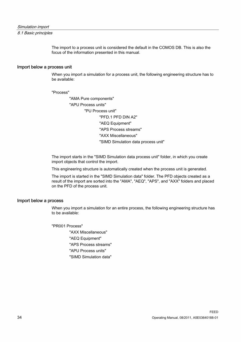
Import below a process unit When you import a simulation for a process unit, the following engineering structure has to be available:
"Process" "AMA Pure components" "APU Process units" "PU Process unit" "PFD.1 PFD DIN A2" "AEQ Equipment" "APS Process streams" "AXX Miscellaneous" "SIMD Simulation data process unit"
The import starts in the "SIMD Simulation data process unit" folder, in which you create import objects that control the import.
This engineering structure is automatically created when the process unit is generated.
The import is started in the "SIMD Simulation data" folder. The PFD objects created as a result of the import are sorted into the "AMA", "AEQ", "APS", and "AXX" folders and placed on the PFD of the process unit.
Import below a process When you import a simulation for an entire process, the following engineering structure has to be available:
"PR001 Process" "AXX Miscellaneous" "AEQ Equipment" "APS Process streams" "APU Process units" "SIMD Simulation data"
Simulation import 8.1 Basic principles
FEED Operating Manual, 08/2011, A5E03640188-01 35
● You must create the PFD as well as the "AEQ", "APS", "AXX", and "SIMD" folders (bold in the graphic) manually. To do this, select the "New" command from the process context menu.
● The other folders and documents or document groups were generated automatically when the process was created.
● Your administrator must have adjusted the relative path reference to the simulation data folder in the import options
In the same way as for the import to a process unit, the following applies:
● The import is started in the "SIMD Simulation data" folder.
● The imported objects are sorted in the "AMA", "AEQ", "APS", and "AXX" folders, and placed on the PFD of the process.
Number of PFs ● There should only be one PFD under the process unit or the process. If COMOS finds
more than one PFD, it places the PFD objects on the first PFD under the process unit or process.
● For Invensys PROII, Chemstations ChemCad, Evonik EbsilonProfessional, AspenTech HYSYS and Honeywell UniSim Design: When you import to a process, define which PFD COMOS document is to be used as the target PFD in the properties of the import document ("Attributes > "Import data" tab, "Import into document" field). COMOS then places the PFD objects on this PFD, even if it is not the first PFD under the process.
8.1.3 General import workflow
● Each import process is controlled by an import document
which is used to configure the import options and start the individual import steps.
● The configuration options are practically identical for each simulator.
● The import process consists of four steps (Aspen: three steps):
– Step 1: Start import
– Step 2: Create PFD objects
– Step 3: Place PFD equipment on PFD (for Aspen: this step is carried out manually)
– Step 4: Place PFD streams on PFD
Terminology In cases where information about the simulation import document or simulation import object applies to all interfaces, the term "import document" is used. You can import as many cases as you wish, but only one case per import.

Simulation import 8.1 Basic principles
FEED 36 Operating Manual, 08/2011, A5E03640188-01
8.1.4 Starting point for the import
"SIMD Simulation data" folder The starting point for the import is in the "SIMD Simulation data" folder.
For each case that you import, you create a simulation case object (referred to as a "SIMCASE" object) in the "SIMD" folder. All data relevant for this import is collected below the SIMCASE - from the import document up to the simulation objects.
Creating a SIMCASE 1. In the Navigator, select the "SIMD" folder of the process unit.
In the context menu of the folder, select the "New > SIMCASE simulation case process unit" command.
2. Open the SIMCASE properties.
3. Go to the "General" tab and enter the name of the case you are importing in the "Name" field.
If you are reimporting a simulation, this step is not carried out. since the SIMCASE already exists.
The import document The import document controls the import process. It covers the following functions:
● Configuration of the import options (optional): In the properties
● Carrying out the import steps:
– Aspen: In the Navigator, via the context menu of the simulation import document or via its properties
– Other simulators: In the Navigator, via the context menu of the simulation import document or via its properties
● Saving important data from the simulation run
● Import log in a log text
The procedure you use to create and configure the import document and start the import steps is described in:
● AspenTech Aspen Plus and Bryan Research & Engineering ProMax import (Page 37).
● Import from Chemstations ChemCad, Evonik EbsilonProfessional, AspenTech HYSYS, Invensys PRO/II, Honeywell UniSim Design (Page 47).

Simulation import 8.2 AspenTech Aspen Plus and Bryan Research & Engineering ProMax import
FEED Operating Manual, 08/2011, A5E03640188-01 37
8.2 AspenTech Aspen Plus and Bryan Research & Engineering ProMax import
8.2.1 Options for XML nodes in the AspenTech Aspen Plus simulator
XML In order for COMOS to be able to create specific subobjects during the course of an Aspen import operation (column trays and components, for example), the XML source file must have the XML nodes listed below.
These XML nodes are automatically available if particular options are employed in AspenTech Aspen Plus:
● B_TEMP:
This XML node is required to create simulation objects for trays (TRSIM) below simulation objects for columns (COLSIM). It is located below the BlockRadfrac XML node.
● X:
This XML node is required to create component simulation objects (MAPSIM) below TRSIM objects. It is located below the BlockRadfrac XML node.
● MOLEFRAC:
This XML node is required to create MAPSIM objects below material stream simulation objects (MSSIM). It is located below the StreamMaterial XML node.
If it should not be available, ensure that the "Fraction basis: Mole" attribute is activated in AspenTech Aspen Plus. To do this, open "Setup > Report Options > Stream".
● ComponentsMain:
This XML node is required to create the CompCalc simulation object (CCSIM), below which the pure simulation components are located. It is located below the XML root node. If it should not exist, ensure that the attribute list for component IDs, formulas and names is activated. To do this, open "Setup > Report Options > Property" in AspenTech Aspen Plus.
Simulation import 8.2 AspenTech Aspen Plus and Bryan Research & Engineering ProMax import
FEED 38 Operating Manual, 08/2011, A5E03640188-01
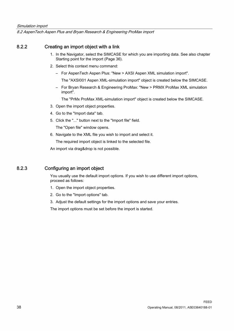
8.2.2 Creating an import object with a link 1. In the Navigator, select the SIMCASE for which you are importing data. See also chapter
Starting point for the import (Page 36).
2. Select this context menu command:
– For AspenTech Aspen Plus: "New > AXSI Aspen XML simulation import".
The "AXSI001 Aspen XML-simulation import" object is created below the SIMCASE.
– For Bryan Research & Engineering ProMax: "New > PRMX ProMax XML simulation import".
The "PrMx ProMax XML-simulation import" object is created below the SIMCASE.
3. Open the import object properties.
4. Go to the "Import data" tab.
5. Click the "..." button next to the "Import file" field.
The "Open file" window opens.
6. Navigate to the XML file you wish to import and select it.
The required import object is linked to the selected file.
An import via drag&drop is not possible.
8.2.3 Configuring an import object You usually use the default import options. If you wish to use different import options, proceed as follows:
1. Open the import object properties.
2. Go to the "Import options" tab.
3. Adjust the default settings for the import options and save your entries.
The import options must be set before the import is started.
Simulation import 8.2 AspenTech Aspen Plus and Bryan Research & Engineering ProMax import
FEED Operating Manual, 08/2011, A5E03640188-01 39
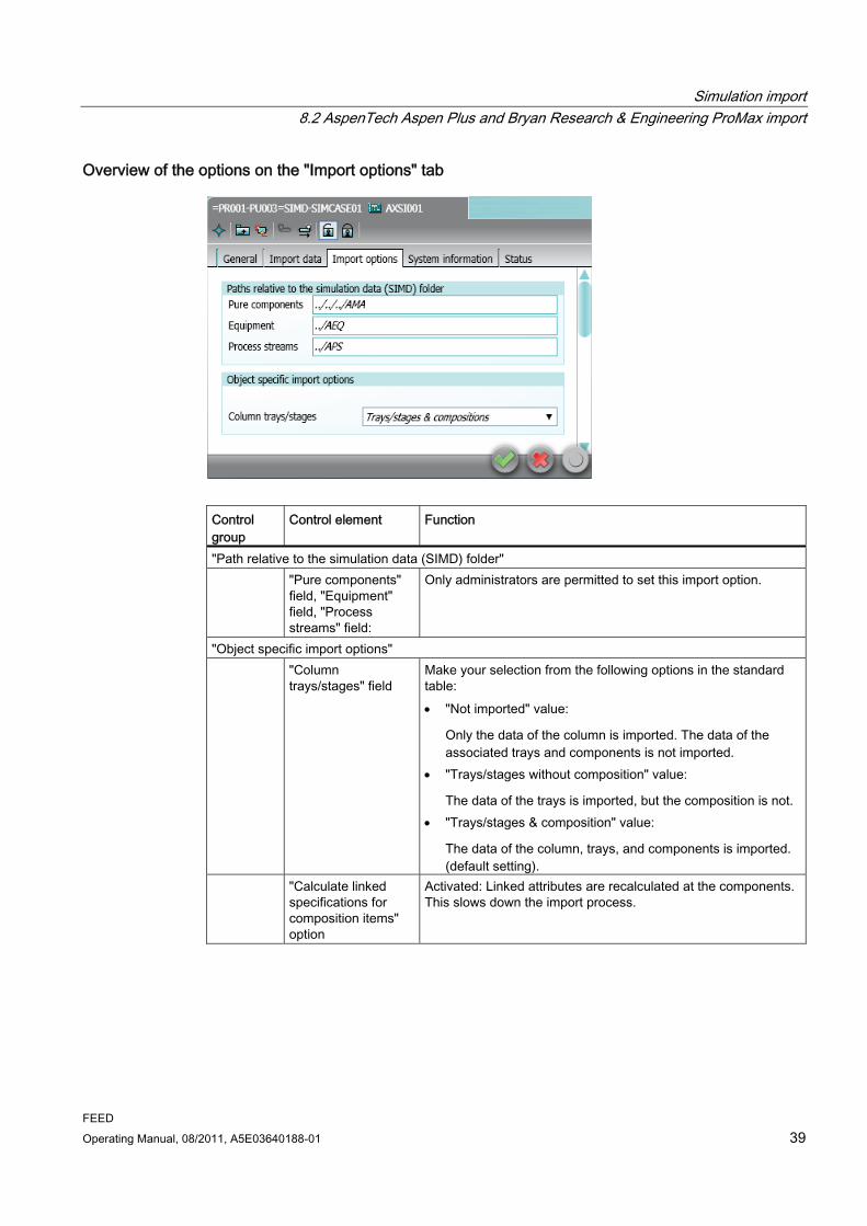
Overview of the options on the "Import options" tab
Control group
Control element Function
"Path relative to the simulation data (SIMD) folder" "Pure components"
field, "Equipment" field, "Process streams" field:
Only administrators are permitted to set this import option.
"Object specific import options" "Column
trays/stages" field Make your selection from the following options in the standard table: "Not imported" value:
Only the data of the column is imported. The data of the associated trays and components is not imported.
"Trays/stages without composition" value:
The data of the trays is imported, but the composition is not. "Trays/stages & composition" value:
The data of the column, trays, and components is imported. (default setting).
"Calculate linked specifications for composition items" option
Activated: Linked attributes are recalculated at the components. This slows down the import process.

Simulation import 8.2 AspenTech Aspen Plus and Bryan Research & Engineering ProMax import
FEED 40 Operating Manual, 08/2011, A5E03640188-01
8.2.4 Import step 1: Start import
8.2.4.1 Introduction The first step involves starting the import and importing the simulation data to COMOS.
You have the following import options:
● Complete import
All objects in a simulation file are imported.
● Partial import
Selected objects in a simulation file are imported.
The partial import can be made from AspenTech Aspen Plus.
8.2.4.2 Complete import
Requirements Your administrator has made an assignment between AspenTech AspenPlus and COMOS units. See also chapter Mapping of units between AspenTech Aspen Plus or Bryan Research & Engineering ProMax and COMOS (Page 123).
Procedure 1. Open the import object properties.
2. Go to the "Import data" tab.
3. Click the "Start import" button.

Simulation import 8.2 AspenTech Aspen Plus and Bryan Research & Engineering ProMax import
FEED Operating Manual, 08/2011, A5E03640188-01 41
Result ● The data from the import file is imported to COMOS. Objects known as simulation objects
are created below the import object for this purpose. The simulation objects are given the same names as the objects in the simulator.
Simulation objects are simply auxiliary objects - you do not edit them. PDF counterparts are automatically created in the second import step for the simulation objects. You then work with these PFD objects.
● The following information from the simulation run is written to the fields in the "Import data" tab:
– "Description simulation run"
– "Date simulation run"
– "User information"
– "User ID"
– "Aspen version" or "ProMax version"
● Entries concerning possible errors or incorrect configurations during the import are logged in the properties of the import object. This information is written to the "Log text" field in the "Import data" tab.
8.2.4.3 Partial import The partial import can be made from AspenTech Aspen Plus.
Requirements Your administrator has made an assignment between AspenTech AspenPlus and COMOS units. See also chapter Mapping of units between AspenTech Aspen Plus or Bryan Research & Engineering ProMax and COMOS (Page 123).
Procedure 1. Select the import simulation in the navigator.
2. Open the properties of the import simulation.
3. Click the "Start partial import" button on the "Import data" tab.
The "Partial import" window opens. See also chapter "Partial import" window (Page 192).
4. You have the option of configuring the view of the objects you want to import in the "Display" control group.
5. Select the objects to be imported in the "Selection" control group or manually in the "Import" column.
6. Click the "OK" button.

Simulation import 8.2 AspenTech Aspen Plus and Bryan Research & Engineering ProMax import
FEED 42 Operating Manual, 08/2011, A5E03640188-01
Result ● The data from the import file is imported to COMOS. For this purpose, so-called
simulation objects are created below the import simulation. The simulation objects are given the same names as the objects in the simulator.
Simulation objects are simply auxiliary objects - you do not edit them. PDF counterparts are automatically created in the second import step for the simulation objects. You then work with these PFD objects.
● The following information from the simulation run is written to the fields in the "Import data" tab:
– "Description simulation run"
– "Date simulation run"
– "User information"
– "User ID"
– "Aspen version" or "ProMax version"
● Entries concerning possible errors or incorrect configurations during the import are logged in the properties of the import object. This information is written to the "Log text" field in the "Import data" tab.
8.2.5 Import step 2: Create PF objects You create PF objects from the simulation objects during the second step. You then work with these PF objects during the subsequent engineering activities.
Procedure 1. Open the import object properties.
2. Go to the "Import data" tab.
– By default, PF objects are created below the process unit under which the import object is located in the Navigator.
– To create them in a different location, make your setting in the "Import in process unit" field.
3. Press the "Create PF objects" button.
Result ● The equipment and process streams are created and automatically sorted into the "AEQ"
and "APS" folders.
For this purpose, COMOS runs a name comparison and only creates the equipment and process streams anew if there are no objects with the same names as those in the "AEQ" and "APS" folders.
● Each piece of equipment adopts the name of its simulation object, which was created during the first import step.
Simulation import 8.2 AspenTech Aspen Plus and Bryan Research & Engineering ProMax import
FEED Operating Manual, 08/2011, A5E03640188-01 43
● Each process stream adopts the name of its simulation material stream, which was created during the first import step.
● Block equipment, for example, a column:
If your administrator has configured the base data accordingly, an entire assembly is created automatically (for example: column, heat exchanger, pump, valve, and container).
The individual components of the assembly are automatically connected to one another as defined by the assembly. COMOS also creates a copy of the PF template that was
prepared in the base project under the assembly, and saves this copy underneath the simulation object of the equipment. Use this copy to place the entire
assembly on the PF before you carry out the third import step. See Import step 3: Place PF streams on the PF (Page 45) for more information about this.
● For columns:
No sections or trays are created; you have to do this manually. The assignment between the theoretical level from the simulation and the actual tray is also carried out manually. More information is provided in Tray mapping (Page 81).
● An equipment case is created underneath the equipment for the imported case along with (under certain circumstances) equipment cases for the standard cases DESIGN, MIN, and MAX.
● If an equipment case with the same name already exists, its values will be overwritten (reimport).
● A material stream for the imported case is created under the process streams, along with (under certain circumstances) material streams for the standard cases DESIGN, MIN, and MAX.
● If a material stream with the same name already exists, its values will be overwritten (reimport).
● If your administrator has prepared the connections accordingly in the base data, the connections of the equipment and the process streams are connected correctly in the database.
● If the simulation uses components that are not yet in the "AMA" folder, these missing components will be created there, along with their group assignments.
● The components are created under the material stream for the imported case.
● Each component gets a pointer to the component assigned to it.
To navigate to the component, select the "Navigate > Implementation" command in the shortcut menu for the component.
● Each component gets a pointer to its components. You find references to these components in the Navigator, underneath the pure component.
You can navigate to a component by calling the shortcut menu for the relevant reference in the Navigator and selecting "Navigate > Object".
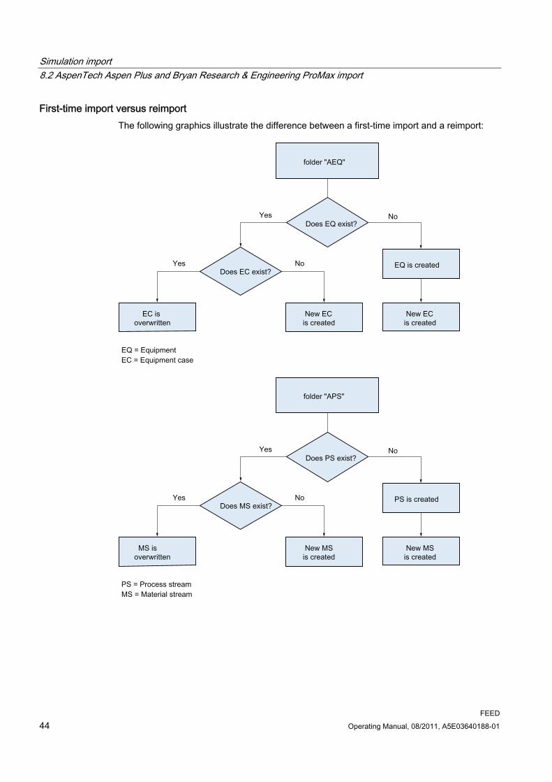
Simulation import 8.2 AspenTech Aspen Plus and Bryan Research & Engineering ProMax import
FEED 44 Operating Manual, 08/2011, A5E03640188-01
First-time import versus reimport The following graphics illustrate the difference between a first-time import and a reimport:
Simulation import 8.2 AspenTech Aspen Plus and Bryan Research & Engineering ProMax import
FEED Operating Manual, 08/2011, A5E03640188-01 45
8.2.6 Import step 3: Place PF streams on the PF
Requirement: Place equipment Before you place the PFD streams in the third step, you must place the equipment on the PFD:
There are two different cases that need to be differentiated when placing the equipment:
1. The equipment is part of an assembly.
2. The equipment is not part of an assembly.
Placing an assembly ● Place any piece of equipment from the assembly on the PFD using drag&drop.
The entire assembly is placed on the PFD.
Background information If a piece of equipment that was created during the second import step is part of an assembly, you find a PFD under the simulation object for the equipment. This PFD is a copy of the PFD template that was prepared in the base project in order to define the assembly. As soon as you place an element of the assembly on the PFD of the process unit, the entire PFD template is placed on the PFD and is then deleted. The collective placing function is not available a second time.
Placing a piece of equipment which is not part of an assembly ● Simply place the equipment on the PFD using drag&drop.
Placing PFD streams Once you have placed the equipment on the PFD manually, you can carry out the third step and place the process streams imported during steps 1 and 2 on the PFD.
1. Open the import object properties.
2. Go to the "Import data" tab.
3. Press the "Place PFD streams" button.
Simulation import 8.2 AspenTech Aspen Plus and Bryan Research & Engineering ProMax import
FEED 46 Operating Manual, 08/2011, A5E03640188-01
Result ● All process streams of the PFD process streams created in step 2 for which the following
applies are placed:
– The process stream is connected to a piece of equipment that is placed on a PFD.
– Properties, "System" tab, "Visible in mass balance" attribute: Activated
– The process stream is connected to a piece of equipment and the equipment is placed on a PFD
● The process stream is placed on the same PFD as the equipment connected to the process stream. If the equipment is located on different diagrams, the process stream is segmented. The segments are then placed, each with a page reference to the other diagram.
● If a piece of equipment that is placed in conjunction with a process stream is placed on multiple PFs, the process stream is placed on the first PFD that COMOS finds
8.2.7 Importing additional cases
Procedure 1. Create an additional SIMCASE in the Navigator. See also chapter Starting point for the
import (Page 36).
2. Create an Aspen import object in the Navigator and create a link to the new import file. See also chapter Creating an import object with a link (Page 38).
3. Open the properties of the import object, select the "Import data" tab and press the "Start import" or "Start partial import" button. See also chapter Complete import (Page 40).
4. Click the "Create PFD objects" button on the "Import data" tab. See also chapter Import step 2: Create PF objects (Page 42).
Result COMOS checks whether the objects that are located below the case import object were already imported for another case. It checks all import objects. The check is based on identical names.
Equipment ● If the equipment has already been imported once, the corresponding PFD object will
already exist and is not recreated. A new case is created below the PFD object.
● If the equipment is being imported for the first time, a new piece of PFD equipment is created and a new case is created below the equipment.

Simulation import 8.3 Import from Chemstations ChemCad, Evonik EbsilonProfessional, AspenTech HYSYS, Invensys PRO/II,Honeywell UniSim Design
FEED Operating Manual, 08/2011, A5E03640188-01 47
Material streams and components ● If the material stream has already been imported for another case, the associated PFD
process stream exists already and, below it, the corresponding PFD material stream also exists.
The material stream for the current case is created in parallel to already the existing material stream. It gets the same name as the current case.
The PFD components are created below the material stream.
● If the material stream has been imported for the first time, a new PFD process stream is created. The process stream gets the same name as the simulation object of the material stream.
A PFD material stream is created below the process stream and gets the same name as the current case.
The PFD components are created below the PFD material stream.
Pure components ● If the pure component already exists in the "AMA Pure components" folder, a new pure
component is not created. Nothing further is done, since pure components do not involve case-specific information.
● If the pure component does not yet exist in the "AMA Pure components" folder, the pure component is created in this folder.
8.3 Import from Chemstations ChemCad, Evonik EbsilonProfessional, AspenTech HYSYS, Invensys PRO/II, Honeywell UniSim Design
8.3.1 Creating an import document
Procedure 1. In the Navigator, navigate to the SIMCASE for which you want to import the data.
2. Open a file explorer and navigate to the simulation file that you wish to import.
3. Use drag&drop to move the query to the SIMCASE.
A dialog appears in which you determine the import mode for the document. You have the option to create a copy of the import file or a link to the original file.
4. It is recommended to create a copy.
Result A simulation import document is created under the SIMCASE. You use this object to import the simulation file to COMOS.

Simulation import 8.3 Import from Chemstations ChemCad, Evonik EbsilonProfessional, AspenTech HYSYS, Invensys PRO/II, Honeywell UniSim Design
FEED 48 Operating Manual, 08/2011, A5E03640188-01
8.3.2 Configuring an import document
Procedure 1. Open the import document properties.
2. Go to the "Import options" tab. See also chapter "Import options" tab (Page 191).
3. Adjust the default settings for the import options and save your entries.
8.3.3 Import step 1: Start import The first step involves starting the import and importing the simulation data to COMOS.
You have the following import options:
● Complete import
All objects in a simulation file are imported.
● Partial import
Selected objects in a simulation file are imported.
The partial import can be made from Invensys PRO/II.
8.3.3.1 Complete import
Requirement You have configured the import options.
Procedure 1. Select the import document in the Navigator.
2. Select the "Start import" command from the context menu of the import document.
As an alternative, you can also open the properties of the import document and select the "Start import" button on the "Attributes > "Import data" tab.
Result ● The data from the import file is imported to COMOS. For this purpose, so-called
simulation objects are created below the simulation import document.
● Information from the simulation run is written to the properties of the simulation import document.
● Entries concerning possible errors or incorrect configurations are logged in the properties of the simulation import document.
Simulation import 8.3 Import from Chemstations ChemCad, Evonik EbsilonProfessional, AspenTech HYSYS, Invensys PRO/II, Honeywell UniSim Design
FEED Operating Manual, 08/2011, A5E03640188-01 49
The import results correspond to those of the AspenTech Aspen Plus import. The description includes a detailed results list. See also chapter Complete import (Page 40).
8.3.3.2 Partial import The partial import can be made from Invensys PRO/II.
Requirement You have configured the import options.
Procedure 1. Select the import document in the Navigator.
2. Open the import document properties.
3. Click the "Start partial import" button on the "Attributes > Import data" tab.
The "Partial import" window opens. See also chapter "Partial import" window (Page 192).
4. You have the option of configuring the view of the objects you want to import in the "Display" control group.
5. Select the objects to be imported in the "Selection" control group or manually in the "Import" column.
6. Click the "OK" button.
Result ● The selected data from the import file is imported to COMOS. For this purpose, so-called
simulation objects are created below the simulation import document.
● Information from the simulation run is written to the properties of the simulation import document.
● Entries concerning possible errors or incorrect configurations are logged in the properties of the simulation import document.
8.3.4 Import step 2: Create PF objects The second import step involves creating PFD objects from the simulation objects. You then work with these PFD objects during the subsequent engineering activities.
Create PFD objects 1. Select the import document in the Navigator.
2. Select the "Create PFD objects" command from the document context menu.
As an alternative, you can also open the properties of the import document and select the "Create PFD objects" button on the "Import data" tab.

Simulation import 8.3 Import from Chemstations ChemCad, Evonik EbsilonProfessional, AspenTech HYSYS, Invensys PRO/II, Honeywell UniSim Design
FEED 50 Operating Manual, 08/2011, A5E03640188-01
Result COMOS creates PFD counterpart objects for all simulation objects imported during step 1.
The import results are the same as those for the AspenTech Aspen Plus import. The results are shown in detail in the description. See also chapter Import step 2: Create PF objects (Page 42).
8.3.5 Import step 3: Place the equipment on the PF
Taking the margins of PFs into account on the report If your administrator has set the report up so that equipment cannot be placed in certain areas on the margins of the report, this is taken into account when equipment is placed automatically. See also chapter Setting margins for automatic placing of equipment on reports (Page 156).
Placing equipment manually As an alternative to placing equipment automatically, you can drag&drop equipment to the report from the "AEQ" folder. See also chapter Placing equipment manually (Page 61).
Procedure for placing equipment automatically 1. Select the import document in the Navigator.
2. Select the "Place PFD equipment" command from the context menu of the import document.
As an alternative, you can open the properties of the import document and select the "Place PFD equipment" button on the "Attributes > Import data" tab.
Result of automatic placing ● COMOS checks which of the PFD equipment that was created during step 2 has not yet
been placed on a plan, and places the objects for this equipment on the first PFD under the process unit.
If you have specified a PFD in the import document properties ("Attributes > Import data" tab, "Import into document" field), the equipment will be placed there.
● If positions have been saved in the simulation object, COMOS uses the coordinates exported from the simulator for placing purposes.
● If one of the simulation objects created during step 1 has a reference to an assembly, the PFD template of the assembly is pasted into the PFD. This occurs at the coordinates specified for the equipment simulation object. The PFD template of the assembly is deleted afterwards.

Simulation import 8.3 Import from Chemstations ChemCad, Evonik EbsilonProfessional, AspenTech HYSYS, Invensys PRO/II,Honeywell UniSim Design
FEED Operating Manual, 08/2011, A5E03640188-01 51
Placing equipment on a different plan To place equipment on a different plan, set a reference to the required plan at the import object in the "Import into document" field on the "Import data" tab.
COMOS uses the coordinates from the simulator for placing purposes.
Distributing equipment to multiple PFs If you wish to distribute equipment to multiple diagrams, you need to do so manually.
In the case of a very large PFD you can, for example, start by placing the complete equipment on a diagram automatically and then distributing it to other diagrams manually.
8.3.6 Import step 4: Place PF streams on the PF
Procedure 1. Select the simulation import document in the Navigator.
2. Select the "Place PF streams" command from the document's shortcut menu.
As an alternative, you can also open the properties of the simulation import document and select the "Place PF streams" button on the "Import data" tab.
Result ● All process streams of the in step 1 and step 2 imported process streams are placed, for
which the following applies:
– The process stream is connected to a piece of equipment that is placed on a PF.
– Properties, "System" tab, "Visible in mass balance on PF" checkbox: Activated
● The process stream is placed on the same PF as its equipment. If the equipment that connects the process stream is located on different diagrams, the process stream is segmented. The segments are then placed, each with a page reference to the other diagram.
● If a piece of equipment to which a process stream is connected was placed on multiple PFs, the process stream is placed on the first PF that COMOS finds.

Simulation import 8.4 Wildcard objects
FEED 52 Operating Manual, 08/2011, A5E03640188-01
8.3.7 Invensys PRO/II: Behavior during reimporting
Automatic deletion during the Invensys PRO/II reimport When you reimport an Invensys PRO/II file, COMOS checks whether any simulation objects that are no longer in the import file are still present under the import document.
If so, these simulation objects are deleted. Any PFD objects that have already been created are not deleted.
As a result, all attribute values that the PFD object has inherited from the simulation object are lost. If an inherited attribute on the PFD object has been overwritten, however, the value is retained.
Example An Invensys PRO/II file is imported. The first two import steps are carried out, i.e. the simulation objects and PFD objects are created.
Equipment A is then deleted in Invensys Pro/II and the file is imported to COMOS once more (same SIMCASE, same import document).
COMOS detects that the simulation object for equipment A is no longer in the file and deletes it. PFD equipment A remains unchanged. All data that the PFD equipment had previously adopted from the simulation object via its equipment case is lost. Data that was checked in at the PFD equipment is retained.
8.4 Wildcard objects
8.4.1 Basic principles
Aim You can import objects from simulation files that are not defined in COMOS with attributes, values, and units to COMOS. Wildcard objects are used for the import.
This function applies to the following simulators:
● AspenTech Aspen Plus
● Bryan Research & Engineering ProMax
● Invensys Operations Management PROII: Only objects are imported in the case of PROII; attributes cannot be imported.
● Evonik EbsilonProfessional
● Honeywell UniSim Design

Simulation import 8.4 Wildcard objects
FEED Operating Manual, 08/2011, A5E03640188-01 53
8.4.2 Importing wildcard objects
Basic principles By default, all attributes found are imported to the relevant COMOS simulation objects for simulation objects that are known to COMOS.
For all simulation objects that are not known to COMOS, all attributes found can be imported into the data list of the relevant wildcard object.
If you need to create simulation types for a simulator which are not to be imported, please contact your administrator, who will then make the necessary settings for the "@1PE > PO > SIM > BLC > DUMMYSIMDummy simulation object" base object. See also Section Settings for importing unknown simulation objects (Page 157).
Procedure 1. Create the required simulation import object in the Navigator.
2. Open the properties of the object.
3. Go to the "Import options" tab.
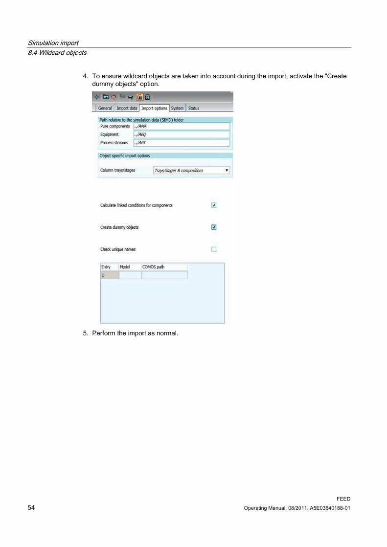
Simulation import 8.4 Wildcard objects
FEED 54 Operating Manual, 08/2011, A5E03640188-01
4. To ensure wildcard objects are taken into account during the import, activate the "Create dummy objects" option.
5. Perform the import as normal.

Simulation import 8.5 Log files for simulator import
FEED Operating Manual, 08/2011, A5E03640188-01 55
Result Wildcard simulation objects are created for objects from the simulation file whose name is not defined in COMOS. You can see the imported attributes on the "Data list" tab.
8.5 Log files for simulator import
Overview All of the following simulator imports create a log file:
● AspenTech HYSYS
● Honeywell Process Solutions UniSim Design
● Chemstations ChemCad
● Invensys Operations Management PRO/II
● AspenTech AspenPlus
● Evonik GmbH EbsilonProfessional
Log file When you perform an import, the "ComosImport" folder is created inside the user's temporary folder. This is where you will find the log file in XML format.
The name of the log file is determined automatically; in the case of Aspen, it is taken from an Aspen attribute.
The log file displays the path to the simulator object under which you performed the import. Additionally, a message is displayed for each object.

Simulation import 8.6 Folder for SIM objects
FEED 56 Operating Manual, 08/2011, A5E03640188-01
8.6 Folder for SIM objects
Folder structure You have the option of creating additional folders for SIM objects, so that folders other than the "AEQ" and "APS" ones are available. To do this, open the base object of the import document in the base project, and click the "Import options" tab. Some folders are already specified in the "Path relative to the simulation data folder (SIMD)" control group.
You will also see a table in which you can configure the folders you require. If settings are made in this table, then the ones in the "Path relative to the simulation data folder (SIMD)" control group will be ignored. If no settings are made in this table, then the ones in the "Path relative to the simulation data folder (SIMD)" control group will apply.
8.7 Batch import of simulation files
8.7.1 Basic principles ● The "Batch Import Control Center" is used to import multiple simulation files at the same
time.
● A link to a suitable PF template for the PF equipment and PF process streams is set by default.
● Your administrator can view this default setting and link a different PF template if required. See also Section Default settings for the simultaneous import of multiple files (Page 156).
8.7.2 Creating "Batch Import Control Center"
Procedure 1. To create a "Batch Import Control Center" object on the "Units" tab in the Navigator,
select one of the two possible storage locations:
– "SIMD" folder below a process
– "SIMD" folder below a process unit
If there is no SIMD folder in the required place, create it using the corresponding command in the shortcut menu of the higher-level folder. See also Section Structure for import below process unit or process (Page 33).
2. Go to the "Base objects" tab in the Navigator. If you are not authorized to access base objects, contact your administrator.
3. Open the "@1PE > PO > SIM > XXSI Simulation import objects" node.
4. Select the "BICCBatch Import Control Center" object.

Simulation import 8.7 Batch import of simulation files
FEED Operating Manual, 08/2011, A5E03640188-01 57
5. Drag&drop this object onto the empty bar underneath the Navigator tree.
A new tab named after the object is displayed towards the bottom of the Navigator.
6. Open the "Units" tab at the top of the Navigator.
7. Drag&drop the selected object from the bottom of the Navigator to the selected "SIMD" folder.
The "BICCBatch Import Control Center" object is created underneath the "SIMD" folder.
8.7.3 Using "Batch Import Control Center"
Requirement There is a "Batch Import Control Center" object below an "SIMD" folder in the "Units" tab. See also chapter Creating "Batch Import Control Center" (Page 56).

Simulation import 8.7 Batch import of simulation files
FEED 58 Operating Manual, 08/2011, A5E03640188-01
Procedure 1. Open the properties of the "Batch Import Control Center" object.
2. Go to the "Batch import" tab.
3. To select a folder as the source for simulation files, click the "..." button next to the "Select
folder" field.
4. To load simulation files from the selected folder, click the "1. Loading sim files" button.
The simulation files are added to the list view below the button. Their name, type, and other information is displayed.

Simulation import 8.7 Batch import of simulation files
FEED Operating Manual, 08/2011, A5E03640188-01 59
The "Import step 3" and "Import step 4" columns are empty in the case of simulation files from AspenTech Aspen Plus or Bryan Research & Engineering ProMax.
5. If necessary, change the settings in the list view:
– To change the simulation type displayed for a simulation file, click the required cell in the "Sim type" column. Select a different simulation type from the selection button.
– To exclude individual steps from the import process, click into the required cell and remove the "X", which is set by default.
– To rename individual field contents, click inside the required cell and edit the required name.
– To import a sim file under a different process unit or under a different sim type, edit the corresponding fields.
6. Click the "2. Creating sim cases + copying sim files" button.
Simulation data is created in the Navigator. Any missing process units and simulation cases are also recreated, if required.
7. If you need to move the running of the batch import to a suitable time, make your settings under "Timer" and, if necessary, "Date":
– To set the timer, select "H" for hour or "Min" for minute and click the "+" or "-" button.
– To set the date, activate the "Activate date (timer default setting)" option. Then enter the required date in the "Start date for batch import" field.
8. To start the "batch import" for all simulation data listed, click the "3. Start batch import" button.
The timer and date settings are applied.
9. Save your entries.

Simulation import 8.7 Batch import of simulation files
FEED 60 Operating Manual, 08/2011, A5E03640188-01

FEED Operating Manual, 08/2011, A5E03640188-01 61
Working in the PF 99.1 Basic principles
A process diagram (PF) is an interactive report. It is used to describe a process unit more precisely:
● By placing its equipment and machines
● By using stream flags for outputting stream data
● By using additional symbols such as plant limits, pipe breaks, and flow direction arrows
In the default configuration, a process stream list with mass balance is automatically inserted in the report header.
Create a PF If you create a process unit, a PF is automatically created at the same time. You can find the PF in the Navigator, directly under the process unit.
9.2 Operation A PF has the same basic properties and functions as all other interactive reports.
The sections that follow provide a brief overview of general methods of operation as well as functions that are specifically relevant to PFs.
You can find detailed information regarding the basic functions and the operation of interactive reports in other manuals. You can find additional information on this topic in the quickstart "Basic", keyword "Interactive reports".
9.3 Manual placing and editing of PF objects
9.3.1 Placing equipment manually If you create your PF manually, you will normally begin by placing the equipment.
Choose from the following two options:
1. Use the PF symbol bar.
2. Use the Navigator.
Working in the PF 9.3 Manual placing and editing of PF objects
FEED 62 Operating Manual, 08/2011, A5E03640188-01
Via the symbol bar The PF symbol bar offers the most important pieces of equipment for you to place, as well as a valve and measuring function:
1. Activate the desired button in the symbol bar.
2. Move the mouse to the desired point in the report and left-click to place the object.
Provided that the button is activated, you can "stamp" the object onto the report as many times as you wish (to place multiple containers at once, for example).
The symbol for the relevant object is placed on the PF.
The object is created in the Navigator and automatically sorted into the "AEQEquipment" folder under the process unit.
Via the navigator 1. Create the equipment in the Navigator: "AEQEquipment" folder, "New > ..." shortcut
menu
2. Place the equipment on the PF using drag&drop.
What are the properties of the equipment? You can find out which properties the individual equipment objects have in Section Specifying equipment (Page 79).
9.3.2 Placing objects from the report bar You can use the report bar to place the following objects:
● Process stream flags
● Tees
● Plant limits
● Flow direction arrow
● Pipe breaks
● Process streams
Procedure 1. Activate the button for the object that you wish to place.
2. Move the mouse to the required point and left-click.

Working in the PF 9.3 Manual placing and editing of PF objects
FEED Operating Manual, 08/2011, A5E03640188-01 63
Result ● The symbol for the relevant object is placed on the PF.
● The object is created in the Navigator.
Exactly where the object is created depends on the object you placed. See also Section Other placeable objects (Page 68) and the subsections relating to each object.
Special case: The "Connection" tool You also find the button for the "Connection" tool on the report bar. This tool is used to draw process streams.
Since this tool is not operated in the same way as the one used for placing a symbol, the "Connection" tool is covered in a separate section. See also Section Working with process streams (Page 65).
9.3.3 Editing objects via the report bar You have the option of using the report bar to edit the properties of some of the objects placed on the PFD.
1. Select the desired object on the PFD.
Several fields appear in the right-hand half of the report bar.
2. Enter the desired values in the fields of the report bar.
3. Save your inputs by clicking the button containing the check mark at the right edge of the report bar.
If there is not enough space on the bar to show all fields, you can make the fields appear by clicking the black arrow.
Your administrator defines which fields are offered for which objects in the base data.
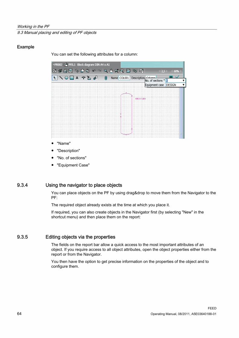
Working in the PF 9.3 Manual placing and editing of PF objects
FEED 64 Operating Manual, 08/2011, A5E03640188-01
Example You can set the following attributes for a column:
● "Name"
● "Description"
● "No. of sections"
● "Equipment Case"
9.3.4 Using the navigator to place objects You can place objects on the PF by using drag&drop to move them from the Navigator to the PF:
The required object already exists at the time at which you place it.
If required, you can also create objects in the Navigator first (by selecting "New" in the shortcut menu) and then place them on the report:
9.3.5 Editing objects via the properties The fields on the report bar allow a quick access to the most important attributes of an object. If you require access to all object attributes, open the object properties either from the report or from the Navigator.
You then have the option to get precise information on the properties of the object and to configure them.

Working in the PF 9.4 Working with process streams
FEED Operating Manual, 08/2011, A5E03640188-01 65
9.4 Working with process streams
9.4.1 The "Connection" tool Process streams are drawn using the "Connection" tool. You can find this tool on the report bar:
Using the "Connection" tool The "Connection" tool is one of the standard tools offered by interactive reports and works in a similar way in all modules.
You use it in the FEED module in the same way as in the PID module. Only difference to the P&ID module: Process streams are created in the FEED module, not pipes.
Additional information This manual assumes that you already have experience of working with the "Connection" tool.
For this reason, the following sections only give you a brief overview of what options you have when creating process streams using the "Connection" tool.
You can find additional information on this topic in the "P&ID" manual, keyword "Connection tool" or "Connector tool".

Working in the PF 9.4 Working with process streams
FEED 66 Operating Manual, 08/2011, A5E03640188-01
9.4.2 Using the "Connection" tool to create process streams
Procedure 1. Select the "Connection" tool on the report bar.
Several text fields appear on the report bar. This is where you specify important properties of the process stream:
2. Define the properties of the process stream on the report bar and confirm what your
inputs.
Field Function "Name" Do not enter anything here. The name will be generated
automatically. "Media class", "Temperature", "Pressure", "Mass flow"
The values you entered are set as the new default values. They do not only apply to the process stream that you are currently drawing, but also to all subsequent process streams you draw until you enter new values.
3. Use the "Connection" tool to connect the equipment.
Result Process streams are created automatically in the Navigator and sorted into the "APSProcess streams" folder underneath the process unit.
Overview of "Connection" tool functions The following options are available when drawing a process stream:
● Set the "Connection" tool on the connectors predefined in the equipment symbol.
● Set the "Connection" tool on any point in the equipment symbol. Doing this will create dynamic connectors.
● You only need to define the start and end points of the process stream; COMOS will then draw in a connecting line automatically.
● To define the precise route that the process stream is to take, define intermediate points.
9.4.3 Creating and placing process streams from the Navigator You can create a process stream and use the "Connection" tool to place it on the PF.
Alternatively, you can create the process stream in the Navigator first and then place it on the PF:
Working in the PF 9.4 Working with process streams
FEED Operating Manual, 08/2011, A5E03640188-01 67
Creating a process stream 1. Select the "APSProcess streams" folder in the Navigator.
2. Select the "New > PS Process stream" command from the shortcut menu.
In the Navigator, a new process stream is created in the "APS" folder.
Placing the process stream from the Navigator on the PF 1. Select the process stream in the "APS" folder.
2. Drag&drop the process stream from the folder to the PF.
The connector tool is activated automatically.
3. You now need to define the start and end points of the process stream.
The process stream you have selected in the Navigator is assigned to the process line you have drawn.
9.4.4 Editing process streams on the PFD A process stream that is already placed can be edited in the following way:
● Change the exact path of the stream by activating the grab points
● Reversing the flow direction of the process stream
● Configure the display of the flows that intersect.
● Setting components on a process stream that has already been drawn.
The process stream is divided up and another process stream is created.
● Specify the key stream data on the PF by placing a process stream flag on the process stream. See also Section Placing process stream flags (Page 69).
9.4.5 Properties of the process streams Below, you will get to know the attributes of a process stream and how to edit them.
Quick access via the report bar The report bar offers a quick way of accessing the most important attributes of a process stream. The following attributes are displayed here:
● "Media class"
● "Pressure"
● "Temperature"
● "Mass flow"
If necessary, your administrator can enable additional attributes to be displayed here.

Working in the PF 9.5 Other placeable objects
FEED 68 Operating Manual, 08/2011, A5E03640188-01
Full access via the properties You can access all attributes of a process stream via its properties, in the "Attributes" tab.
Overview of the process stream tabs The following tabs are relevant for the work you carry out in the FEED module:
Tab Application "Material stream list".
Here you find an overview in tabular format of all material streams of the process stream. The table contains the most important data for the material streams. The values can be edited. You can find information on material streams in Section Material streams (Page 85). You can find information on the data flow between material streams and process streams in Section Data flow between a process stream and its material streams (Page 94).
"Actual stream data"
This is where you define which material stream is the active case of the process stream. The tab reads out the most important general stream data for this material stream.
"Technical data" This is where you find the mechanical data for the process stream. "Display" Here you have the option of defining the graphical properties of the process
stream on the PF. "System" "Visible in mass balance on PF" option: See Section Configuring mass balances
(Page 72). "Hydraulic case list"
Only if the process stream has hydraulic cases. Here you find an overview in tabular format of all hydraulic cases of the process stream. The table contains the most important data for the hydraulic cases. The values can be edited.
9.5 Other placeable objects
9.5.1 Overview You can use the report bar to place the following objects on the PFD:
Button Object Created in Navigator under
Process stream flag Purely graphical symbol. No object is created.
Tee In "AEQ" folder
Battery limit In the "AXX" folder

Working in the PF 9.5 Other placeable objects
FEED Operating Manual, 08/2011, A5E03640188-01 69
Button Object Created in Navigator under
Flow direction arrow PFD
Pipe break PFD
9.5.2 Placing process stream flags 1. Activate the "Process stream flag" button on the report bar.
2. Move the mouse to the desired process stream. It turns yellow as soon as the mouse touches the process stream.
3. Left-click to drop the flag.
Result ● The flag is placed on the PF and connected to the process stream.
● It reads out the process stream data.
● If the process stream is moved or deleted, the flag is moved or deleted along with it.
● A process stream flag is a purely graphical symbol. No object is created for it in the Navigator.
Symbol display on the PF A process stream flag reads out the following properties of the process stream that is connected to it:
● Name
● Temperature
● Pressure
● Mass flow
9.5.3 Using pipe breaks
Placing a pipe break 1. Activate the "Pipe break" button on the report bar.
2. Move the mouse to the desired process stream. It turns yellow as soon as the mouse touches the process stream.
3. Left-click to drop the break.

Working in the PF 9.5 Other placeable objects
FEED 70 Operating Manual, 08/2011, A5E03640188-01
Result
● A pipe break is created under the PF.
● The process stream will appear broken on the PF.
● The process stream will be retained in its entirety in the database, but will be segmented, meaning that two segments will be created under the process stream in the Navigator. If you select the stream on the PF, only the segment up to the break will be selected, not the entire stream. The "Navigate" context command will also move to the segments.
Changing the gap or symbol size To increase or decrease the gap between the segments or symbols of the pipe break you have to activate the grab points of the symbol using two separate left-clicks:
● Changing the gap:
Move the grab point in the center of the symbol (here: the grab point on the right).
● Changing the symbol size:
Move the grab point at the end of the S-shaped bend in the symbol (here: the grab point on the left).
9.5.4 Creating page references FEED distinguishes between the following types of page reference:
1. Type: Automatic page reference
2. Type: Using a sheet connector object

Working in the PF 9.5 Other placeable objects
FEED Operating Manual, 08/2011, A5E03640188-01 71
Type 1: Creating an automatic page reference If you are using a process stream on multiple PFs (pages), COMOS automatically inserts a page reference.
● Open the first PFD and place the process stream.
● Open the second PFD.
● In the Navigator, navigate to the process stream.
● Drag&drop the process stream from the Navigator to the second PFD.
Result ● The process stream is segmented. The segments are now placed on the PFs.
● A page reference is automatically inserted on both PFs.
The flow direction and, therefore, the source ("from") and target ("to") roles depend on which segment is created first: The segment called SEG1 is always the source stream, while the one called SEG2 is the target stream.
To change the flow direction, swap the names of the segments.
Type 2: Placing a sheet connector A sheet connector is a symbol that bundles the links across sheets of a report visually at a certain point.
You have to place the sheet connector manually:
1. Open the two PFs between which there should be connections.
2. Go to the "Base objects" tab in the Navigator.
3. For each PFD: Drag&drop the following base object from the Navigator to the PFD: "@1PE > PO > XX > UB1 Sheet connector".

Working in the PF 9.6 Configuring mass balances
FEED 72 Operating Manual, 08/2011, A5E03640188-01
Result ● The sheet connector is placed on the PFs.
● An engineering object for the sheet connector is created below each of the PFs, meaning
that each PFD has its own sheet connector.
1. For each PFD: Connect the process streams that you intend to link to the other PFD to the sheet connector.
To increase the number of connectors, activate the grab points on the sheet connector symbol and enlarge the symbol.
2. Open the properties of one of the two sheet connectors, go to the "Attributes > Reference" tab and drag&drop the other sheet connector from the Navigator to the "To referenced drawing" field.
Result The references to the other PFD in each case are automatically created in the two sheet connector symbols:
9.6 Configuring mass balances You have the option of configuring the contents and layout of the following mass balances:
● Process unit, "MMB.1 > 02 Material balance, short" document group
● The mass balance that is displayed on the PFD.
There are the following configuration options:
● Which process streams are incorporated?
● In what order do the process streams appear?
● Which components are incorporated?
● In what order do the components appear?
Working in the PF 9.6 Configuring mass balances
FEED Operating Manual, 08/2011, A5E03640188-01 73
Procedure 1. Open the PFD properties and go to the "Attributes > Document options" tab.
2. Activate the "Display process stream list on PFD" option.
3. Activate the "Group components" option.
4. Go to the "Material Balance" subtab.
5. Determine which process streams appear in the process stream list and in what order.
6. Determine which components appear in the mass balance and in what order.

Working in the PF 9.6 Configuring mass balances
FEED 74 Operating Manual, 08/2011, A5E03640188-01
Selecting and arranging process streams 1. Click the "Stream selection" button.
The "Stream selection" window opens.
Number Option Function 1 "Available streams" list: The list displays all streams that are located
under the process unit and in whose properties the "Visible in mass balance on PFD" option is activated on the "System" tab.
2 "Selected streams" list: This is where you see all streams that are output in the process stream list.
3 "Add all", "Add"; "Remove", and "Remove all" buttons:
This is where you define which of the available streams appear in the process stream list.
4 "To top", "Top", "Down", and "To bottom" buttons:
This is where you define the order in which the process streams are displayed in the process stream list.
2. Move the required process streams to the "Selected streams" list.
3. Determine the order in which the streams are to appear in the "Selected streams" list.
If a process stream does not appear in the "Stream selection" window, this means the "Visible in mass balance on PFD" option has been deactivated in its properties in the "System" tab.
Working in the PF 9.7 Grouping components
FEED Operating Manual, 08/2011, A5E03640188-01 75
Activate this option if you want the process stream to appear on the mass balance of the PFD.
Selecting and arranging components To open the "Component grouping" window, click the "Group components" button. The window is available at several points in the engineering structure. See also chapter Grouping components (Page 75).
9.7 Grouping components
Grouping components You use the "Component grouping" window to configure which components appear in the following mass balances, and in what order:
● Process unit, "MMB.1Mass balances" document group: "02Material balance, short" evaluating report
● Mass balance of a PF.
Inherit configuration The window is available at several points in the engineering structure.
1. At the process.
2. At the process units.
3. At evaluating report "02Material Balance, short", which is located under the process units in the "MMB.1Mass balances" document group.
4. At the PFs.
The layout defined for a node further down in the tree structure overwrites the one defined for a node higher up in the tree. Therefore, the component grouping settings made in the properties of a PF overwrite the component grouping settings made at the process unit or at the process.
Opening the Group components window ● Process and process unit: Properties, "Material Balance" tab: Click the "Group
components" button.
● "MMB.1Mass balances", "02Material balance, short" document group: Properties, "Attributes > Material balance" tab: Click the "Group components" button.
● PF: Properties, "Attributes > Material balance" tab: Click the "Group components" button.
The "Component grouping" window opens.

Working in the PF 9.8 Adding an equipment list to the PF
FEED 76 Operating Manual, 08/2011, A5E03640188-01
Using the "Component grouping" window Use the options listed in the table below to carry out the following steps:
1. Create groups.
2. Sort the components into the groups.
3. Define the order in which components and groups are listed.
"Component grouping" window user interface reference Work area Description Tree structure with the following elements:
All components that are used in the process or process unit
All groups into which the components in the mass balance are sorted.
Buttons Description "Group": You use this option to create a group and move all
components selected in the tree structure to a location under this group. The components in the mass balance are sorted under the group.
"Undo group": This is where you dissolve the group selected in the tree structure. The components are moved back to the top level of the tree.
"To top", "Top", "Down", and "To bottom":
You use these options to define the order in which the groups and components are displayed in the mass balance. The components or groups selected in the tree structure are moved accordingly.
"Hide", "Show": Here, you can show and hide components and groups in the mass balance.
"Reset": Use this button to apply the default setting. If component grouping settings have been defined at the
process unit, these are used. If component grouping settings have not been defined at
the process unit, but have been defined at the process, the component grouping settings for the process are used.
9.8 Adding an equipment list to the PF You can add an equipment list to the PF.

Working in the PF 9.8 Adding an equipment list to the PF
FEED Operating Manual, 08/2011, A5E03640188-01 77
Procedure 1. Open the PF properties and go to the "Attributes > Document options" tab.
2. Activate the "Display equipment list on PF" option.
Result ● A list containing all equipment placed on the PF appears in the lower half of the PF.
● The list reads out the data for the case entered as the active case for the equipment.

Working in the PF 9.8 Adding an equipment list to the PF
FEED 78 Operating Manual, 08/2011, A5E03640188-01
FEED Operating Manual, 08/2011, A5E03640188-01 79
Specifying equipment 1010.1 General properties
10.1.1 Determining the main equipment for a process unit 1. Open the properties of the process unit and go to the "General data" tab.
2. In the Navigator, open the "AEQ" folder located under the process unit.
3. Drag&drop the required equipment from the Navigator to the "Main equipment" field in the properties of the process unit:
Result The equipment is assigned as the main equipment. Its description is output on the process unit symbol on the block diagram.
10.1.2 Evaluating reports for the equipment The COMOS DB is set up in such a way that the following document groups are automatically created underneath the equipment:
● "PDS Process data sheet"
● "TDS Mechanical data sheet"
You can find detailed information on these document groups and their evaluating reports in Section Evaluating reports under the equipment (Page 103).
10.1.3 Graphical display You have the option of changing the graphical display of the equipment on the PF. To do this, select the symbol on the PF:
● Shortcut menu, "Options" command:
As with all COMOS modules, you can mirror the symbol, edit its symbol text, and edit the symbol in the symbol editor.
● Equipment properties, "Graphical parameters" tab, "Symbol description" field:
Determine label to be displayed on the PF.

Specifying equipment 10.2 Calculating pump attributes in MS Excel
FEED 80 Operating Manual, 08/2011, A5E03640188-01
● Shortcut menu, "Graphical properties" command: Some symbols can be expanded to include agitators and drives.
● Report bar:
Depending on which equipment you have selected, the report bar offers fields that you can use to change the display of the symbol.
Example:
– Heat exchanger: "Symbol type" field
– Function: "Output and operation" and "Processed with" fields.
10.1.4 Maximum and minimum design pressure and maximum and minimum design temperature
The equipment automatically takes its minimum and maximum design pressure and minimum and maximum design temperature values from the process streams connected to it.
You find these attributes in the equipment properties "Design data" tab.
More information on automatic data flow can be found in section Data flow from process stream to the connected equipment (Page 97).
10.2 Calculating pump attributes in MS Excel Some pump process data, such as the electrical power, can be calculated using Excel table calculation methods. The calculation is always based on a case.
Requirements ● Excel must be installed on your workstation.
● Make sure that your local Excel settings allow other applications to write information to Excel:
Excel menu "Tools > Macro > Security", "Trusted publishers" tab: Activate the "Trust access to visual basic project" option.
Procedure 1. Open the properties of the pump, "Process data" tab:
2. The description texts for the attributes to be exported to Excel are shown in red. The calculation is based on these attributes. Make sure that the attributes are not empty.
3. In the Navigator, select the equipment case for which the calculation is to be made from underneath the pump.
4. Create the Excel table by selecting "New > PumpCalculation Pump Calculation" in the shortcut menu.

Specifying equipment 10.3 Tray mapping
FEED Operating Manual, 08/2011, A5E03640188-01 81
5. Double-click the Excel table in COMOS to open it, and then close it again.
The values are exported to Excel, calculated, and imported to COMOS.
6. Open the properties of the pump and go to the "Process data" tab. The description text for the attributes calculated in Excel and imported to COMOS appear in purple. The attribute fields appear in orange as their values now differ from the statically linked values for the active case.
7. Check the updated attribute values (for example, the electrical power).
8. Accept the differences for an attribute by right-clicking the description text of the attribute and selecting the "Static link: Always accept difference" command from the shortcut menu.
10.3 Tray mapping
Assigning physical information from the simulation to trays The first step of a simulation import involves importing the physical information relating to the theoretical levels to COMOS. However, no trays are created under the PFD column during the second import step.
If you wish to assign physical information to column trays, you need to create the trays and then carry out the assignment manually as part of a process known as "tray mapping".
10.4 Assigning a different base object
Procedure To assign a different base object to existing equipment, proceed as follows:
1. Select one of the following options:
– In the Navigator, right-click the required object of the PFD equipment.
– Open the PFD and right-click a placed object.
2. Select the "Change Base Object" command from the context menu.
The base objects with which you can replace the selected object are listed under the "Change Base Object" command.
3. Click the desired base object.
Result Once you have changed the base object in the Navigator, the documents that use this object are also changed. Once you have changed the base object on the PFD, the corresponding object in the Navigator also changes.

Specifying equipment 10.5 HTRI import/export
FEED 82 Operating Manual, 08/2011, A5E03640188-01
10.5 HTRI import/export
Supported functions ● Heating curves
● Design cases for pipe bundle heat exchangers
● Air cooler designs
Call using object You can only use the HTRI import/export in COMOS if the HTRI base software has been installed and activated with the dongle. Reason: COMOS uses an HTRI-API for the import and export.
The HTRI import/export is integrated in the COMOS DB under specific base objects:
● See also chapter "@1PE > PO > SIM > SUB > HCSIM Heating Curve Simulation Object" (Page 171).
● See also chapter "@1PE > PO > EQ > 04 > HEX Heat Exchanger" (Page 178).
Example The following example describes how to carry out the HTRI import/export for the heat exchanger:
1. Create a process in a project with a link to the FEED project structures. To do this, right-click the open project or the open working layer and select the "New > PR Process" command in the context menu.
2. Right-click the process and select the "New > AEQ Equipment" command in the context menu.
3. Right-click the "AEQ Equipment" folder and select the "New > 04 heat transport > HEX heat exchanger" command in the context menu.
4. Expand the structure below the heat exchanger. Here you will find, among others, the case object "DESIGN case".
In the context menu of this case object you will find the entry "Xist HTRI case/pipe design-case".
Certain script blocks are used in the associated base object "@1PE > DS > @O > HTRI".
The DLL-Browser The HTRI import must be controlled via script by the "ComosHTRIImport.dll" file. For this purpose, first check the "ComosHTRIImport.dll" file in the DLL browser. The DLL-browser can e.g. be found in the help menu of the script editor.
1. Click the "Extra > Object debugger" command in the menu bar.
2. Click the "Help" button.

Specifying equipment 10.5 HTRI import/export
FEED Operating Manual, 08/2011, A5E03640188-01 83
3. In the "Script: components, declarations" window, click on the "Declaration" tab.
At the very top there is a list. You can also add this list from the Microsoft Explorer using drag&drop.
4. Select the desired DLL file in the Microsoft Explorer; in this case:
"<COMOS>\OCX\Import\ComosHTRIImport.dll" or
"<COMOS>\Bin\OCX\Import\ComosHTRIImport.dll"
5. Drag the "ComosHTRIImport.dll" file to the DLL browser.
6. Click one of the methods or properties.
Help text is displayed in the comment area.
Example You can find the "Xist_StandardCase_1.htri" file in the "<COMOS>\Help\English\06_Other documentation" folder. This is an example provided by Heat Transfer Research HTRI. This example can only be opened if Heat Transfer Research HTRI is installed and is activated by means of the dongle.
Affected standard tables You can find additional information on this topic in the "COMOS Administration" manual, keyword "EQ equipment".
Additional base objects "@System > @D > @DocumentTypeMapping > HTRI HTRI-Import"

Specifying equipment 10.5 HTRI import/export
FEED 84 Operating Manual, 08/2011, A5E03640188-01

FEED Operating Manual, 08/2011, A5E03640188-01 85
Case-specific data 1111.1 Basic principles
In COMOS, case-specific data for equipment and process streams is managed in self-contained objects. These objects are located in the Navigator underneath their PF object.
The advantage of this separation is that the data structure remains clearly arranged even when there are many cases for a single process unit.
The COMOS DB is configured in such a way that the run-specific data is displayed directly on the PF objects and can be edited there.
For the same reason, the components are managed separately from the pure components.
11.2 Creating case-specific objects Case-specific objects can be created in two ways:
● Import the required case from a simulation.
The corresponding case-specific objects are created in the database. These objects contain the simulation data. See also Section Simulation import (Page 33).
● Use the Run Case Manager.
The corresponding case-specific objects are created in the database. The objects do not yet contain any data. See also Section Managing cases (Page 111).
11.3 Standard cases Standard cases are cases that are automatically created under each process stream and each piece of equipment. In the COMOS DB, these are the "DESIGN", "MAX", and "MIN" cases.
11.4 Material streams
11.4.1 Basic principles In COMOS, case-specific data for a process stream is managed in the form of material stream objects. The material streams are located directly underneath the process stream in the Navigator.

Case-specific data 11.4 Material streams
FEED 86 Operating Manual, 08/2011, A5E03640188-01
The attributes of the material streams are linked to the attributes of their process stream, enabling you to view and edit the most important case-specific data directly in the properties window for the process stream.
11.4.2 Editing material streams
Where do I determine the properties of material streams? You have three options for determining the properties of material streams:
1. By means of a simulation import
2. In the properties of the process stream
3. In the properties of the material stream concerned
Option 1: Simulation import Perform a simulation import. The material stream takes over all data that is specified by the simulation.
Option 2: Properties of the process stream ● "Actual stream data" tab: You have the option of editing the general stream data for the
material stream that is set as the active case.
● "Material stream list" tab: The most important attributes of all material streams in the process stream (such as temperature, pressure, and mass flow) are displayed here.
Please contact your base data administrator if you would like additional attributes to be added to this list.
Option 3: Properties of the material stream You can edit all attributes of a material stream in its properties.

Case-specific data 11.4 Material streams
FEED Operating Manual, 08/2011, A5E03640188-01 87
Overview of the properties of a material stream The following material stream tabs are relevant for your work:
● "Components" tab:
– This is where see which components were assigned to the material stream and the values these have. You have the option of assigning additional components. See also Section Determining the components of a material stream (Page 89).
– "Mass fraction" and "Molar fraction" columns: COMOS calculates the sum of the individual values. You can find this sum in the lower half of the tab, above the horizontal scroll bar.
● "General stream data" tab:
The attributes "Mass flow" and "Molar stream" are calculated automatically: COMOS adds the values of the "Mass flow" and "Molar stream" columns in the "Components" tab, and enters the total in the "Mass flow" and "Molar stream" attributes.
● "Solid phase" tab:
Self-explanatory
● "Liquid phase 1" tab:
Self-explanatory
● "Liquid phase 2" tab:
Self-explanatory
● "Gas phase" tab:
Self-explanatory
11.4.3 Determining the active material stream 1. Open the properties of the process stream and go to the "Actual stream data" tab.
2. Select the active material stream in the "Active material stream (case)" field.
11.4.4 Using material streams with identical values
Link the attributes of the material streams. In some cases, it may be necessary for material streams to work with the same attribute values. For this reason, you have the option of linking the attributes in the material stream list, on the "Material stream list" tab at the process stream.
This means that you only need to edit the attribute at one material stream (source attribute); COMOS will write the corresponding value to all material streams to which you have linked this attribute (target attributes).
Case-specific data 11.4 Material streams
FEED 88 Operating Manual, 08/2011, A5E03640188-01
Requirements It is not possible to link just any attributes, but rather only attributes of the same column.
Principle ● You establish the link via drag&drop, or by selecting the required command from the
shortcut menu for the material stream list.
● The data only flows in one direction: from the source attribute to the target attributes.
● COMOS uses a static link, which means that if the value of the target attribute differs from that of the source attribute, this is indicated by means of an orange signal at the target attribute. You apply the linked value via the shortcut menu for the target attribute cell.
Overview of the commands in the shortcut menu for the material stream list Command Function "Apply min. value of column", "Apply max. value of column"
See "Linking minimum values and maximum values" later in this documentation.
"Delete link for material stream" Deletes all links that were set for attributes of this material stream in the material stream list.
"Delete link for attribute" Deletes the link for the attribute whose shortcut menu was called.
"Update static links for material stream" Updates all links that were set for attributes of this material stream in the material stream list.
"Update static links for attribute" Updates the link for the attribute whose shortcut menu was called.
Linking an attribute to the minimum value or maximum value of the column 1. Open the properties of the process stream and go to the "Material stream list" tab.
2. Left-click the cell of the target attribute and select the "Apply min. value of column" or "Apply max. value of column" command from the shortcut menu.
Result ● COMOS checks which cell of the current column contains the lowest or highest value and
links the target attribute to this cell.
● If a different cell contains a lower value at a later point in time, the link will not be reset automatically; instead, you will need to call the "Apply min. value of column" command again and establish a new link.

Case-specific data 11.5 Components
FEED Operating Manual, 08/2011, A5E03640188-01 89
How to determine which two attributes are linked ● Open the properties of the process stream and go to the "Material stream list" tab.
● In the material stream list, left-click the cell of the source attribute, i.e. the attribute of the material stream whose value you wish to pass on.
● Drag&drop the source attribute from the list to the cell of the target attribute, that is, the attribute of the material stream to which the value is to be applied.
The target attribute is linked to the source attribute.
11.4.5 Determining the components of a material stream
Procedure Open the "AMA Components" folder in the Navigator and drag&drop the required components to the "Components" tab.
Result A component that has a reference to this component is created under the material stream.
Procedure for taking components from another material stream Call the shortcut menu and the "Copy components from > ..." submenu from the "Components" tab, and select the name of the required case as the command.
Result The components of the material stream that you have selected are applied to the material stream.
11.5 Components
11.5.1 Basic principles Case-specific material data for a process stream is managed in components. The components are located directly underneath the material stream of the corresponding case.
Each component has a reference to the component on which it is based.
Case-specific data 11.5 Components
FEED 90 Operating Manual, 08/2011, A5E03640188-01
11.5.2 Editing components
Where do I determine the properties of components? You have three options to determine the properties of components:
1. By means of a simulation import
2. In the properties of the material stream
3. In the properties of the component concerned
Option 1: Simulation import Perform a simulation import. Applies all data that is specified by the simulation to the component.
Option 2: Properties of the material stream ● "Components" tab: This is where the most important attributes of all components of the
material stream are displayed.
Please contact your base data administrator if you would like additional attributes to be added to this list.
Option 3: Component properties You can edit all attributes of the component here.
Overview of the properties of a component The following tabs of a component are relevant for your work:
● "Component data":
This is where you enter the material data for the component.
● "Pure component data":
This is where the pure component data of the assigned component is displayed for informational purposes. The data cannot be edited.
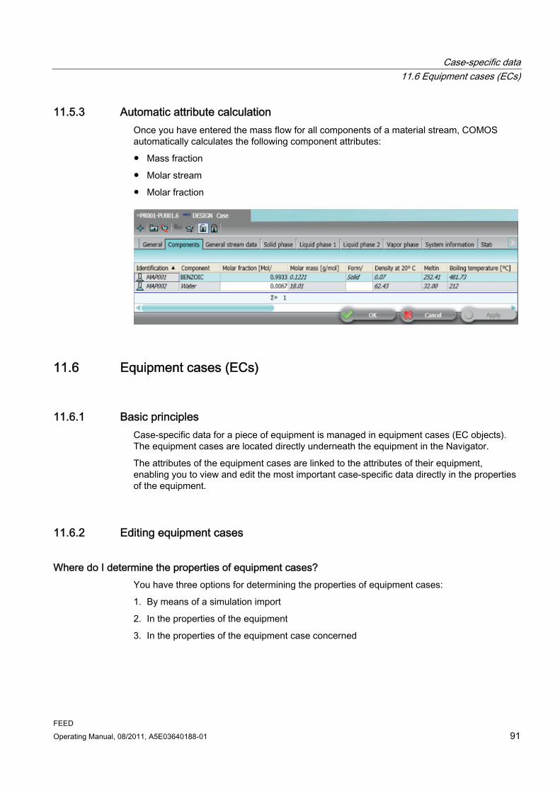
Case-specific data 11.6 Equipment cases (ECs)
FEED Operating Manual, 08/2011, A5E03640188-01 91
11.5.3 Automatic attribute calculation Once you have entered the mass flow for all components of a material stream, COMOS automatically calculates the following component attributes:
● Mass fraction
● Molar stream
● Molar fraction
11.6 Equipment cases (ECs)
11.6.1 Basic principles Case-specific data for a piece of equipment is managed in equipment cases (EC objects). The equipment cases are located directly underneath the equipment in the Navigator.
The attributes of the equipment cases are linked to the attributes of their equipment, enabling you to view and edit the most important case-specific data directly in the properties of the equipment.
11.6.2 Editing equipment cases
Where do I determine the properties of equipment cases? You have three options for determining the properties of equipment cases:
1. By means of a simulation import
2. In the properties of the equipment
3. In the properties of the equipment case concerned
Case-specific data 11.6 Equipment cases (ECs)
FEED 92 Operating Manual, 08/2011, A5E03640188-01
Option 1: Simulation import Perform a simulation import. All data that is specified by the simulation is applied to the equipment case.
Option 2: Equipment properties ● "Process data" tab: You have the option of editing the process data for the material
stream that is set as the active case.
● "Technical data" tab: You have the option of editing the technical data for the equipment case that is set as the active case.
● "Cases": This is where the most important attributes of all equipment cases of the process stream are displayed.
Please contact your base data administrator if you would like additional attributes to be added to this list.
Option 3: Properties of the equipment case You can edit all attributes of an equipment case in its properties.
Overview of the properties of an equipment case The following tabs of an equipment case are relevant for your work:
● "Process data" tab:
Self-explanatory
● "Technical data" tab:
Self-explanatory
11.6.3 Determining the active equipment case 1. Open the properties of the equipment and go to the "Process data" tab.
2. In the "Equipment case" field, select the active equipment case and save this setting.

FEED Operating Manual, 08/2011, A5E03640188-01 93
Data flow 1212.1 Overview
In the FEED module, data is exchanged between the following PF objects. For the most part, the data flows by means of automated processes.
● Boundary stream <-> assigned process stream
● Process stream <-> material streams
● Material stream <-> components
● Equipment <-> equipment cases
● Equipment <-> connected process streams
12.2 Data exchange between boundary stream and assigned process stream
Application case If your engineering work begins with a block diagram, you can enter the initial stream data as early as at the boundary stream and then pass it on to the assigned process stream.
Values changed later at the process stream can be written back to the boundary stream.
Requirement: Assign the process stream to a boundary stream To enable data exchange between boundary stream and process stream, you must first assign a process stream to a boundary stream. To do this, proceed as follows:
1. Open the properties of the boundary stream.
2. In the Navigator, navigate to the process stream you want to assign.
3. Drag&drop the process stream to the "Process stream" field in the "Current stream data" tab in the boundary stream properties.
The process stream is assigned to the boundary stream.
Data flow: How to pass data from the boundary stream to the process stream 1. Open the properties of the boundary stream and go to the "Current stream data" tab.
2. Select the "To process stream" entry from the list in the "Reference" control group.
3. Press the "Copy values" button.
The stream data is passed on to the process stream, "Current stream data" tab.
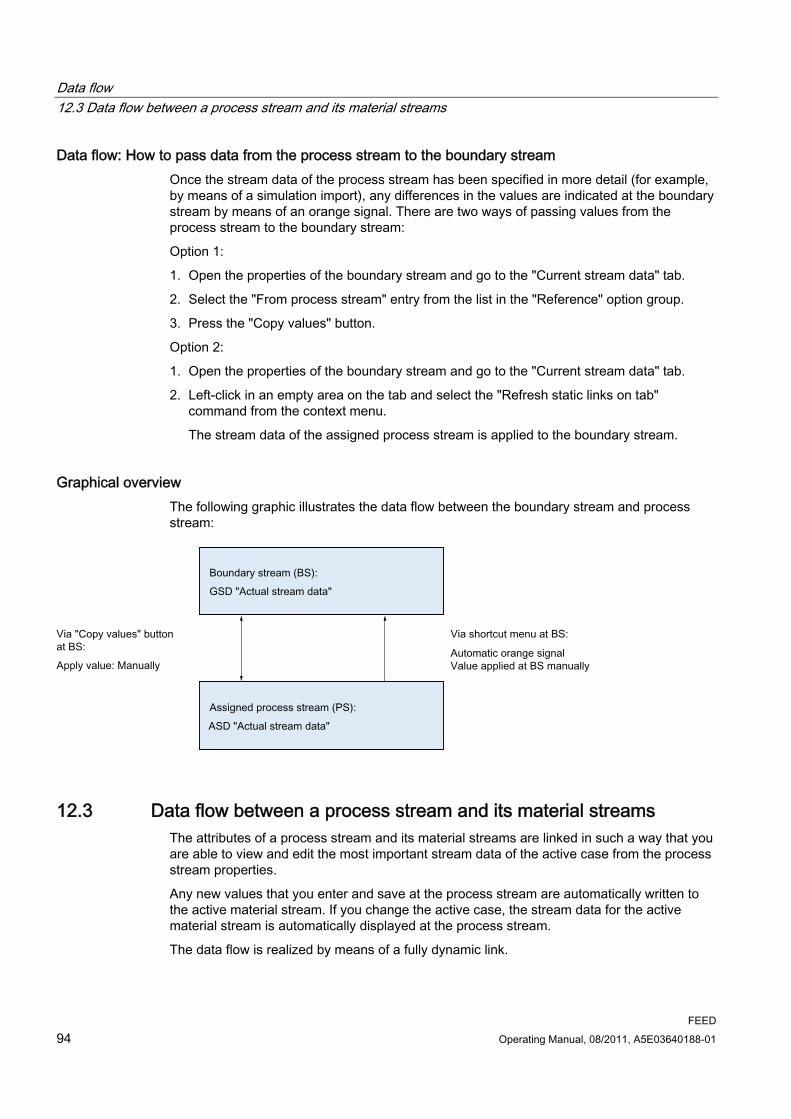
Data flow 12.3 Data flow between a process stream and its material streams
FEED 94 Operating Manual, 08/2011, A5E03640188-01
Data flow: How to pass data from the process stream to the boundary stream Once the stream data of the process stream has been specified in more detail (for example, by means of a simulation import), any differences in the values are indicated at the boundary stream by means of an orange signal. There are two ways of passing values from the process stream to the boundary stream:
Option 1:
1. Open the properties of the boundary stream and go to the "Current stream data" tab.
2. Select the "From process stream" entry from the list in the "Reference" option group.
3. Press the "Copy values" button.
Option 2:
1. Open the properties of the boundary stream and go to the "Current stream data" tab.
2. Left-click in an empty area on the tab and select the "Refresh static links on tab" command from the context menu.
The stream data of the assigned process stream is applied to the boundary stream.
Graphical overview The following graphic illustrates the data flow between the boundary stream and process stream:
12.3 Data flow between a process stream and its material streams The attributes of a process stream and its material streams are linked in such a way that you are able to view and edit the most important stream data of the active case from the process stream properties.
Any new values that you enter and save at the process stream are automatically written to the active material stream. If you change the active case, the stream data for the active material stream is automatically displayed at the process stream.
The data flow is realized by means of a fully dynamic link.

Data flow 12.4 Data flow between the components and their material stream
FEED Operating Manual, 08/2011, A5E03640188-01 95
Requirement: Determine the active case 1. Open the properties of the process stream and go to the "Current stream data" tab.
2. Select the active case from the "Active material stream (case)" list.
"Material stream list" tab for the process stream Here, you get an overview in table format of all material streams of the process stream and of their most important data. The values can be edited.
"Current stream data" tab for the process stream The attributes of the "Current stream data" tab are linked to the attributes of the "General stream data" tab of the active material stream.
Graphical overview The following graphic illustrates the data flow between the process stream and active material stream:
12.4 Data flow between the components and their material stream The attributes of a material stream and its components are linked in such a way that you are able to view and edit the most important material data of the components from the material stream properties.
The data flow is realized by means of a dynamic link.
Requirement: Components have already been assigned to the material stream Components must have been assigned to the material stream.

Data flow 12.5 Data flow between the equipment and its equipment cases
FEED 96 Operating Manual, 08/2011, A5E03640188-01
"Component data" tab for the material stream Here, you find an overview in table format of all components of the process stream and their most important data. The values can be edited.
"Actual stream data" tab for the material stream The values for the "Mass flow" and "Molar stream" attributes of the material stream are automatically calculated from attribute values of the components.
12.5 Data flow between the equipment and its equipment cases The attributes of a piece of equipment are linked to its equipment cases in such a way that you are able to view and edit the most important run-specific data from the equipment properties.
Any new values that you enter and save at the equipment are automatically written to the active equipment case. If you change the active case, the stream data for the active equipment case is automatically displayed at the equipment.
The data flow is realized by means of a fully dynamic link.
Requirement: Determine the active case 1. Open the properties of the equipment and go to the "Technical data" tab.
2. Select which equipment case is the active case using the "Active material stream (case)" list.
"Cases" tab for the equipment Here, you find an overview in table format of all equipment cases and their most important data. The values can be edited.
"Technical data" tab for the equipment The attributes of the "Technical data" tab are linked to the attributes of the "Technical data" tab of the active case.
"Process data" tab for the equipment The attributes of the "Process data" tab are linked to the attributes of the "Technical data" tab of the active case.
With some equipment, the attributes are distributed across multiple tabs, for example, the "Process data - general", "Process data - tube side", and "Process data - air side" tabs in the case of air coolers.

Data flow 12.6 Data flow from process stream to the connected equipment
FEED Operating Manual, 08/2011, A5E03640188-01 97
Graphical overview The following graphic illustrates the data flow between the equipment and active case:
12.6 Data flow from process stream to the connected equipment The equipment automatically takes its minimum and maximum design temperature and minimum and maximum design pressure values from the process streams connected to it.
● At the equipment, you find these attributes on the "Design data" tab.
● At the process streams, you find corresponding attributes on the "Current stream data" tab.
The data flow is realized by means of a dynamic link.
Minimum design temperature The process stream with the lowest temperature value of all process streams connected to the equipment is identified and this value is automatically entered at the equipment, in the "Design temperature, min." field on the "Design data" tab.
Exactly the same procedure is followed for the "Design temperature, max.", "Design pressure, min.", and "Design pressure, max." attributes.
If the project option "Change from dynamic to static on first change" is activated, you may enter a different value at the equipment. The data between the equipment and the process stream is then no longer consistent.

Data flow 12.6 Data flow from process stream to the connected equipment
FEED 98 Operating Manual, 08/2011, A5E03640188-01
Graphical overview The following graphic illustrates the data flow between the equipment and connected process stream:

FEED Operating Manual, 08/2011, A5E03640188-01 99
Evaluating reports 1313.1 Evaluating reports under the process
Overview of the evaluating reports of the process The following graphic provides an overview of the document groups and evaluating reports found under a process:
"PFB.3Equipment list, total" document group This is where you find the following evaluating reports:
● "01Title page":
Contains a general description of the document title and document contents.
● "02Equipment List, total":
Lists the complete equipment for the process. The "AEQ" folders for all process units are evaluated.

Evaluating reports 13.2 Evaluating reports of the "ABS boundary streams" folder
FEED 100 Operating Manual, 08/2011, A5E03640188-01
"PFB.4Equipment lists" document group This is where you find the following evaluating reports:
● "01Title page":
Contains a general description of the document title and document contents.
● "02Equipment list, mechanical processing" to "10Pipe run list":
The entire equipment of the process is divided into eight categories. An individual equipment list is created for each category.
"PFB.5 Mass balances" document group This is where you find the following evaluating reports:
● "01Title page":
Contains a general description of the document title and document contents.
● "02 Mass Balance, short":
The mass balance for all process units of the process, in a short version. The active case is evaluated.
● "03 Mass Balance":
The mass balance for all process units of the process. A separate sheet is reserved for each process unit. The active case is evaluated.
13.2 Evaluating reports of the "ABS boundary streams" folder
Overview of the evaluating reports of the "ABS" folder The following graphic provides an overview of the document groups and evaluating reports found in the "ABS" folder:
"BSL Boundary stream list" document group This is where you find the following evaluating reports:
● "01 Title page":
Contains a general description of the document title and document contents.
● "02 Boundary stream list":
The boundary stream list provides an overview of the most important data of all boundary streams used in the process.

Evaluating reports 13.3 Evaluating reports in the "AMA components" folder
FEED Operating Manual, 08/2011, A5E03640188-01 101
13.3 Evaluating reports in the "AMA components" folder
Overview of the evaluating reports in the "AMA" folder The following graphic provides an overview of the document groups and evaluating reports found in the "AMA" folder:
"MAL Component list" document group This is where you find the following evaluating reports:
● "01 Title page":
Contains a general description of the document title and document contents.
● "02 Component list":
This list provides an overview of the most important data of all components used in the process.
13.4 Evaluating reports under the process units
Overview of the evaluating reports of a process unit The following graphic provides an overview of the document groups and evaluating reports found under a process unit:

Evaluating reports 13.4 Evaluating reports under the process units
FEED 102 Operating Manual, 08/2011, A5E03640188-01
"MMB.1 Mass balances" document group This is where you find the following evaluating reports:
● "01 Title page":
Contains a general description of the document title and document contents.
● "02 Material Balance, short":
The material balance for the process unit, in a short version.
You have the option of configuring the contents and layout of the material balance: Material balance properties, "Material balance" tab:
– "Actual case":
Determine which case is to be evaluated. If you do not enter anything here, the case that is active at the process stream will be evaluated.
– "Template":
Choose between a short or an extended display mode.
– "Stream selection":
Determine which process streams are incorporated into the material balance. See Configuring mass balances (Page 72).
– "Group components": Determine which components are incorporated into the material balance and in what order. See Grouping components (Page 75).
● "03 Mass balance":
The mass balance for the process unit. A separate sheet is reserved for each process stream.
You have the option of determining which case is evaluated: Evaluating report properties, "Attributes" tab, "Document-parameters" tab, "Active material stream (case)" field.
If you do not enter anything here, the case that is active at the process stream will be evaluated.
"PFB.1 Equipment lists" document group This is where you find the following evaluating reports:
● "01 Title page":
Contains a general description of the document title and document contents.
● "02 Equipment list, total":
A list of the complete equipment located under the process unit in the "AEQ" folder
● "03 E&IC position list":
A list of all the instrumentation located under the process unit in the "AEQ" folder
● "04 Line list (pipes)":
A list of all pipe branches that were created by converting a PFD to a P&ID.

Evaluating reports 13.5 Evaluating reports under the equipment
FEED Operating Manual, 08/2011, A5E03640188-01 103
Creating additional documents and document groups In the context menu for the process unit, the "New" command offers additional document groups. If you have questions concerning one of these document groups, please contact your administrator.
13.5 Evaluating reports under the equipment
Overview of the evaluating reports for a piece of equipment The graphic below provides an overview of the document groups and evaluating reports found under a piece of equipment:
"PDS Process data sheet" document group This is where you find the following evaluating reports:
● "01 Title page":
Contains a general description of the document title and document contents.
● "02 Process data":
Reads out the most important process data for the equipment, displays the symbol for the equipment, and contains a field for general comments.
● "03 Process stream data":
Reads out the most important stream data for the process streams connected to this equipment. All cases are displayed. A page is reserved for each case.
"TDS Mechanical data sheet" document group This is where you find the following evaluating reports:
● "01 Title page":
Contains a general description of the document title and document contents
● "02 Technical data":
Reads out the mechanical data for the equipment and contains a field for general comments.
● "03"
Lists the nozzles located under the equipment, including nominal width, nominal pressure, and pipe spec.

Evaluating reports 13.5 Evaluating reports under the equipment
FEED 104 Operating Manual, 08/2011, A5E03640188-01

FEED Operating Manual, 08/2011, A5E03640188-01 105
PF and P&ID report 1414.1 Converting a PF into a P&ID
Workflow 1. Create P&ID templates for the PF equipment.
2. Create a P&ID.
3. Place the PF on the P&ID and dissolve the PF.
Creating P&ID templates Create P&ID templates for the objects in the "AEQ" folder. You have two options:
● Use the default templates: See Using P&ID default templates (Page 107).
● Select the templates yourself: See Selecting your own P&ID template (Page 108).
The "@PEASSEMBLY" node is inserted under the PF objects in the Navigator. The P&ID objects of the assembly and a P&ID that maps the assembly are located under this node.
No pipes are created in this step. The connectors of the P&ID equipment are not yet connected.
Creating the P&ID ● Select the process unit and then, from the shortcut menu, select the "New > PID P&ID"
command.
The "PID" folder is created under the process unit. You find a P&ID report in the "PID" folder.

PF and P&ID report 14.1 Converting a PF into a P&ID
FEED 106 Operating Manual, 08/2011, A5E03640188-01
Placing and dissolving the PF The P&ID objects that are created automatically as a result of creating the template do not need to be placed and connected manually on the P&ID. Instead, you place the PF on the P&ID and then dissolve the drawing.
1. Open the P&ID.
2. Drag&drop the process unit PF from the Navigator to the P&ID. Place it in the top left-hand corner.
The objects and symbols placed on the PF are displayed on the P&ID, together with the anchor symbol of the PF:
3. Select the anchor symbol of the PF and, from the shortcut menu, select the "Convert
placed document" command.

PF and P&ID report 14.2 Using P&ID default templates
FEED Operating Manual, 08/2011, A5E03640188-01 107
Result ● If an object that has a P&ID assembly is placed on the PF, the objects in the assembly
are placed on the P&ID.
● The objects placed on the P&ID are connected to one another by means of pipes (pipes, pipe branches, and segments). Tees for branches are inserted automatically.
Pipes that connect objects in an assembly are created under the assembly in the Navigator.
Pipes that connect two assemblies are created under the corresponding process streams in the Navigator.
● Tees for branches are automatically inserted in the P&ID and are created under the assemblies in the Navigator.
Optimizing the graphic You need to make adjustments to the P&ID manually to optimize the graphic Since the assemblies are initially still grouped, you will need to undo the grouping for this purpose.
1. Select an assembly.
2. Select the "Grouping > Undo" command from the shortcut menu.
14.2 Using P&ID default templates If you are using default templates, you have the option of creating templates for all objects of a process unit at once, or creating one for an individual object.

PF and P&ID report 14.3 Selecting your own P&ID template
FEED 108 Operating Manual, 08/2011, A5E03640188-01
Creating default templates for all objects under the process unit 1. Open the properties of the process unit and go to the "General data" tab.
2. Select the "Copy default PID + CM templates" button.
The default assemblies are created under the PFD objects.
Creating a default template for an individual object 1. Select the object in the Navigator or on the PFD.
2. Select the "Select default template" command from the context menu.
The default assembly is created under the PFD object.
How does COMOS determine which default template is used? Your administrator has already determined which assembly is to be used as the default assembly in the base data beforehand, using the properties for the PFD objects ("System" tab, "Pointer" control group, "Standard PID+CM template" field).
14.3 Selecting your own P&ID template
How to proceed 1. Select the object in the Navigator.
2. Select the "Select P&ID template" command from the shortcut menu.
The "Select template" window opens.
3. Select a template and confirm your selection with "OK".
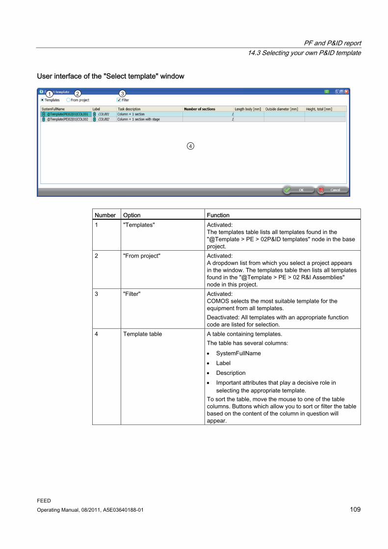
PF and P&ID report 14.3 Selecting your own P&ID template
FEED Operating Manual, 08/2011, A5E03640188-01 109
User interface of the "Select template" window
Number Option Function 1 "Templates" Activated:
The templates table lists all templates found in the "@Template > PE > 02P&ID templates" node in the base project.
2 "From project" Activated: A dropdown list from which you select a project appears in the window. The templates table then lists all templates found in the "@Template > PE > 02 R&I Assemblies" node in this project.
3 "Filter" Activated: COMOS selects the most suitable template for the equipment from all templates. Deactivated: All templates with an appropriate function code are listed for selection.
4 Template table A table containing templates. The table has several columns: SystemFullName Label Description Important attributes that play a decisive role in
selecting the appropriate template. To sort the table, move the mouse to one of the table columns. Buttons which allow you to sort or filter the table based on the content of the column in question will appear.

PF and P&ID report 14.4 Creating multiple P&IDs from a PF
FEED 110 Operating Manual, 08/2011, A5E03640188-01
14.4 Creating multiple P&IDs from a PF
Procedure To create multiple P&IDs from a PF, you have to distribute the equipment across several P&IDs manually. To do this, proceed as follows:
● Create P&ID templates for the PF objects.
● In the Navigator, navigate to the P&ID objects under the @PEASSEMBLYnode.
● Place the P&ID equipment on the P&IDs.
● Click an empty area of the P&ID workspace and select the "Connect automatically" command from the shortcut menu.
Result The P&ID objects are automatically connected on the report. The corresponding pipes, pipe branches, and segments are created in the database.
14.5 Data flow between PF objects and P&ID objects The COMOSDB is configured in such a way that all relevant data from the PF equipment and process streams is applied to the P&ID objects and pipe branches without any data being lost.
The details of this data flow are configurable.

FEED Operating Manual, 08/2011, A5E03640188-01 111
Managing cases 1515.1 Basic principles
You manage the cases for your process on the "Case manager" tab. See also Section "Case manager" user interface reference tab: (Page 111).
The Case Manager is available at two levels of your engineering structure:
● At process level:
Any action that you carry out in the Case Manager applies to the entire process.
● At process unit level:
Any action that you carry out in the Case Manager only applies to the process unit.
15.2 "Case manager" user interface reference tab: Open the properties of the process or process unit in the Navigator and go to the "Case manager" tab.
Buttons Button Function "Set active case" button 1. Select the active case in the standard table on the right-
hand side.
The table lists all cases located under the process or process unit in the structure.
2. Press the button.
The case is entered as the active case at all equipment and process streams.
"Create new case" button 1. Enter the name of the new case in the field on the right-hand side.
2. Press the button.
Equipment cases and material streams are created with this name under all equipment and process streams.
"Complete" 1. Select a case in the standard table on the right-hand side. 2. Press the button.
An equipment case is created, unless one with the same name is already present under a piece of equipment. A material stream is created, unless one with the same name is already present under a process stream.

Managing cases 15.2 "Case manager" user interface reference tab:
FEED 112 Operating Manual, 08/2011, A5E03640188-01
Button Function "Delete case" 1. Select a case in the standard table on the right-hand side.
2. Press the button.
All equipment cases and material streams with the same name are deleted.
"Rename case" 1. Enter the new name for the case in the field on the right-hand side.
2. Press the button.
The "Rename case" window opens. 3. Enter the new name of the case and press the "OK" button
to confirm your entry.
All equipment cases and material streams with the same name are renamed.
"Copy case" 1. Select a case in the standard table on the right-hand side. 2. Press the button.
The "Copy case" window opens. 3. Enter the name of the new case and press "OK" button to
confirm your entry. Result: A copy of the selected equipment case with the name you
have specified is created under each piece of equipment. A copy of the selected material stream with the name you
have specified is created under each process stream. If COMOS cannot find the selected case, it does not create
a copy.
"Actions work on" control group Option Function "Mass balance reports" Activated (default setting): When you press the "Set active
case" button, the case that you have just selected is evaluated on the mass balances. The settings in the properties of the mass balances and process streams are ignored.
"Equipment" Activated (default setting): The actions you perform using the buttons on the left are also applied to the equipment. This means that new equipment cases are created, existing ones are renamed, and so on. Deactivated: The actions are not applied to the equipment.
"Process streams" Activated (default setting): The actions you perform using the buttons on the left are also applied to the process streams. This means that new material streams are created, existing ones are renamed, and so on. Deactivated: The actions are not applied to the process streams.

Managing cases 15.2 "Case manager" user interface reference tab:
FEED Operating Manual, 08/2011, A5E03640188-01 113
Other control elements Control element Function "Log text" field COMOS logs the result of the action in this text field. "Extended log texts" option Self-explanatory

Managing cases 15.2 "Case manager" user interface reference tab:
FEED 114 Operating Manual, 08/2011, A5E03640188-01

FEED Operating Manual, 08/2011, A5E03640188-01 115
Cost estimation 1616.1 Purpose
Overview You have the option of making a rough cost estimation during the planning stage. Cost data for assigned FEED objects is linked as a basis for calculation. The estimated unit costs are based on the total costs associated with the PFD equipment plus the process streams.
16.2 Calculation basis for cost estimation
Procedure Select the "New > U06 Calculation basis for cost estimation" command from the context menu of the project node.
"History of the cost index" tab The "Index: changes to previous year (%)" table shows the percentage change of the prices for each year. Enter the values in chronological order.
The attributes that are linked to the table depend on the attributes entered in the "Value1" column of the "Standard tables > @CE > CE > CE015 Index groups" standard table. This standard table is stored on the cost basis objects for the relevant attributes. The stored values are used to calculate the deduction or surcharge affecting the old prices.
"Overhead rates" tab The percentage surcharges for category overhead rates are entered in the table. The surcharges are read out by selecting the category on the cost objects. The values and labels are entered in the "Standard tables > @CE > CE > CE012 Category overhead rates" standard table.
16.3 Cost basis object
Procedure To create a cost basis object, select the "New > ..." command from the context menu of the "CB Calculation basis for cost estimation" node.

Cost estimation 16.4 Cost object
FEED 116 Operating Manual, 08/2011, A5E03640188-01
"Cost index reference group" tab Enter the prices from the reference year in this tab.
Example: The data for pipes is entered for the "H Pipes" cost basis object.
The columns "Material" and "PN" are linked with the relevant standard tables. The columns with the nominal diameters are named after the column "Value 1" in the standard table for nominal diameters. You can find more information on this topic in the "PipeSpec Designer" manual, keyword "Standard table for nominal diameters".
You enter the materials in the "Material" column. For each material, you need to create however many lines are required for the nominal pressures that are to be used. Enter the price per unit in the next columns. To transfer the data to the table on the "Index group costs" tab, click the "Initialize project year table" button.
"Index group costs" tab In this tab, you set the index group for the object, through which the total index is calculated. The total index states the percentage price change in relation to the reference year.
To apply the price change to the individual prices, click the "Calculate cost basis" button.
In the case of the "E Heat exchanger, cooler" cost basis object, the "Index group costs" tab is based on a polynomial rather than a table. You have the option of selecting the "Polynomial" entry from the "Calculation mode" list. Values "P1" to "P6" are specified for this. The parameters in the Excel file are transferred into the fields "P1" to "P6" in the tab via the mapping table.
16.4 Cost object
Overview You create the cost objects below the FEED objects. The costs are calculated in these objects.
Procedure Select the "New > CE Cost estimation > Material costs" command in the context menu of the FEED object.
"Material costs" tab If you change the value in the "Category overhead rates" field, then the value from the table linked in the "Linked cost table" field is read.
For the calculation, the part costs are multiplied by the quantity. The overhead rates are added to this and multiplied by the value entered in the "Factor" field.

Cost estimation 16.5 Offer basis object
FEED Operating Manual, 08/2011, A5E03640188-01 117
16.5 Offer basis object
Overview You can use the "Offer basis object" object to select older offers as the source for calculation.
Procedure 1. Select the "New > Z_OB Offer basis" command from the context menu of the "CB
Calculation basis for cost estimation" node.
2. Select the "New > 001 Offer basis object" command from the context menu of the "OB Offer basis" node.
"Offer reference year" tab You define the "Reference year" and the "Costs" in this tab.
"Costs project year" tab As with the cost basis object, you create the index group on this tab. The calculation returns the value for the project year. See also chapter Cost basis object (Page 115).

Cost estimation 16.5 Offer basis object
FEED 118 Operating Manual, 08/2011, A5E03640188-01
FEED Operating Manual, 08/2011, A5E03640188-01 119
Knowledge base 1717.1 Basic principles
Definition The knowledge base consists of a set of engineering rules that define when alarms or warning messages are to be issued for a process. These rules are defined in queries.
Execute these queries in order to check whether a process follows the rules. You have two options:
● Check all rules at once. Critical objects are marked in color in the Navigator.
● Check an individual rule. The result is displayed on the rules tab.
What rules are there? ● Some engineering rules are pre-configured in the COMOSDB, for example, "Check
process stream design temperature".
● Your administrator can set up additional rules in the base object tree.
17.2 Creating the knowledge base, status display
Procedure 1. Select the process in the Navigator.
2. Select the "New > AKB knowledge base" command from the context menu.
The "AKB knowledge base" folder is created under the process.
3. To create a query, select the "AKB" folder and then select the "New > ..." command in the context menu to select the rule you require:
– "RU000 General rules"
– "RU001 Check process stream design temperature"
– "RU002 Pump pressure too high"
– "RU003 Temperature too high"
The selected rule is created in the folder.
4. Create all rules that apply to your process.

Knowledge base 17.3 Checking a process
FEED 120 Operating Manual, 08/2011, A5E03640188-01
Activating the status display for the knowledge base in the Navigator 1. Click an empty area of the Navigator.
2. Select the "Status display > 13 Knowledge base" command from the context menu.
On the basis of the rules in the knowledge base, each object is assigned a color according to its status.
17.3 Checking a process
Checking a process against all rules ● Select the "AKB" folder and then select the "Check rules" command from the context
menu.
Result ● The entire process is always checked.
● All rules of the folder are executed.
● The results of the check are displayed in color in the Navigator:
Color Status Red Error Yellow Warning Light blue Note Green OK
Checking a process against an individual rule ● Open the desired rule by double-clicking it.
The rule automatically checks the entire process.
● To check a specific node of the process (a process unit, for example), drag&drop the node to the "Starting point" field.
The rule automatically checks all objects under this node.
● The result of the check is displayed in the window of the rule, in the following columns:
– Error
– Warning
– Note
● Erroneous values are indicated by an orange background in the value columns.
● It is possible to correct invalid values directly at this point.

Knowledge base 17.3 Checking a process
FEED Operating Manual, 08/2011, A5E03640188-01 121
Example: "Check process stream design temperature" query
● When you open this query, you see different default columns. Do not delete the "Error",
"Warning", and "Message" columns.
● You will also see various columns that display attributes. You can delete these columns or add new columns with attributes.

Knowledge base 17.3 Checking a process
FEED 122 Operating Manual, 08/2011, A5E03640188-01

FEED Operating Manual, 08/2011, A5E03640188-01 123
Administration 1818.1 Mapping of units between AspenTech Aspen Plus or Bryan
Research & Engineering ProMax and COMOS To import the attribute values correctly to COMOS, you must set up an assignment between the units of the simulation files and the COMOS units.
You must add entries to the standard tables accordingly whenever new units are added to the simulation files. You can find additional information on this topic in the "COMOS Administration" manual, keyword "Standard tables".
Standard tables This assignment is made using the following standard tables:
● "@1PE Process engineering > AE Aspen units"
● "@1PE Process engineering > PRMX ProMax units"
Column Description "Name" This column contains the units as they are defined in XML in the "unit" attributes of a
node. "Value1" This column contains the name of the assigned COMOS unit as defined in the COMOS
unit system.
Additional information about AspenTech Aspen Plus Below this standard table, additional standard tables are defined which help to differentiate between AspenTech Aspen Plus units that belong to multiple physical unit groups. The physical unit groups are defined in XML using the "domain" attribute. The name of this table corresponds to the name of the "domain" attribute ("@1PE Process engineering > AE Aspen units > HEAD Aspen units for domain HEAD", for example).
During an import, the tables below the "@1PE Process engineering > AE Aspen units" standard table are evaluated first, and then the "@1PE Process engineering > AE Aspen units standard table.

Administration 18.2 Using the knowledge base rule editor
FEED 124 Operating Manual, 08/2011, A5E03640188-01
18.2 Using the knowledge base rule editor
Procedure To open the rule editor, proceed as follows:
1. Open a query below the "AKB Knowledge Base" folder.
2. Right-click a column header.
3. Select the "Define rule" command from the context menu.
Result The "Edit rule" window is displayed. In addition to the default columns "Error", "Warning", and "Message", it also contains an entry for each column you have created in the query.
To define the conditions for the rules, drag the column headers (and with them the attributes) to one of the following fields:
● "Error condition"
● "Warning condition"
● "Message condition"
18.3 Modifying the standard import
18.3.1 Überblick Functions controlling the sequence of the import operation are defined on the "Script" tabs of the following objects: the base objects of the import objects, the base objects of the simulation objects, and the buttons that start the import steps.
In the COMOSDB, these functions call the standard import operation.
Modification However, you have the option of modifying the standard import operation by extending the functions via the script. In this way you can, for example, import attributes that are not considered by the standard import, or change the way the attributes are assigned in comparison to the standard import.
In the script, the full scope of the standard COMOS script functions is available.
See also Import objects: Buttons (Page 125)
Simulation objects (Page 126)

Administration 18.3 Modifying the standard import
FEED Operating Manual, 08/2011, A5E03640188-01 125
18.3.2 Import objects: Buttons On the "Import data" tab, the import objects have various buttons that start the individual import steps.
Each of these buttons has an OnClick() script that controls the import step in question.
The following commands within the OnClick() script start the standard import:
● Invensys PRO/II, AspenTech HYSYS, Chemstations ChemCad, Honeywell UniSim Design and Evonik EbsilonProfessional:
– "BUTTON1 Start Import":
Workset.lib.pe.Simulation.StartImport ThisObject
Starts the first import step.
StartImport() creates an instance, calls its Import(), and transfers the CDevice of the import object as a parameter.
– "BUTTON2 Create PFD Objects":
Workset.lib.pe.Simulation.CreatePFDObjects ThisObject
Starts the second import step.
– "BUTTON3 Place PFD Equipment":
Workset.lib.pe.Simulation.PlaceObjectsOnPFD1 owner.owner, Nothing
Starts the third import step.
– "BUTTON4 Place PFD Streams":
Workset.lib.pe.Simulation.PlaceStreamOnPFD1 owner.owner
Starts the fourth import step.
● AspenTech HYSYS:
– "BUTTON5 Objects on subflowsheets"
Workset.lib.Pe.PlaceObjectsOnMultiplePFD GetSpecOwner,
GetSpecOwner.spec("ID.ND0249").LinkObject, true
Creates additional PFDs and places equipment on sub-flow charts.
● AspenTech Aspen Plus:
– "BUTTON1 Start Import"
Workset.lib.pe.Simulation.StartImport ThisObject
Starts the first import step.
If necessary, the scripts can be modified by means of additional commands. Do not delete the commands, otherwise you will completely replace the standard import function with your own import function.
However, the actual modification of the standard import function takes place in the user script blocks of the simulation objects.

Administration 18.3 Modifying the standard import
FEED 126 Operating Manual, 08/2011, A5E03640188-01
18.3.3 Simulation objects
18.3.3.1 Überblick
Functions Each base object underneath "@1PE > PO > SIM" defines multiple functions on the "Script" tab. These functions control what happens with this object during the first two import steps.
The start of the function body calls the standard import function for the object. The standard import can be extended in the subsequent lines.
References See also:
● Section AspenTech Aspen Plus: Class AspenNode (Page 130)
● Section Bryan Research & Engineering ProMax (Page 138)
● Section AspenTech HYSYS: Class HYSYSNode (Page 148)
● Section Invensys PRO/II:Class ProIINode (Page 143)
● Section Honeywell UniSim Design: Class UniSimNode (Page 151)
● Section Evonik EbsilonProfessional: Class EbsilonNode (Page 151)
● Section Chemstations ChemCad: Class ChemCad Node (Page 153)
This way you can, for example, import attributes that are not imported via the standard import, or change the way in which attributes are assigned compared with the standard import.
Do not delete the call for the standard import.
Exception The standard import operation should not be executed at all for this object but is replaced completely by a script that is defined in the function.
This involves the following functions:

Administration 18.3 Modifying the standard import
FEED Operating Manual, 08/2011, A5E03640188-01 127
Function Description [InterfaceName]Import(Node As Object) This function is called for each simulation object shortly before
the end of the first import step. See also section Import() (Page 128). A reference to the node object of the simulation object is transferred as a parameter. You can use this function to import attributes that are not imported by the standard import. You have to consider that these attributes must exist on the simulation object and its PF object. If this is not the case, they must be created in the base data beforehand. If you want to modify how attributes are assigned in the standard import, you need to undo the value assignments made via the standard import in the script before reassigning the attributes as required. Following applies in both cases: In order to also pass the modified settings for the standard import to the PF object, the attribute linking between the simulation object and PF object must be modified accordingly. If new attributes were added, you may need to modify the report templates of evaluation reports that should work with these attributes.
[InterfaceName]ImportDone(Node As Object) Called once the Import() function for all simulation objects has
been executed and is responsible for post-calculations. A reference to the node object of the simulation object is transferred as a parameter. Example: Conversion of the molar density into mass density. See also section ImportDone() (Page 129).
SimulatorImport(DevSimObj As IcomosDDevice) This function is called for each simulation object in the second
import step. A reference to the import object is transferred as a parameter. See also section SimulatorImport() (Page 130).
SimulatorImportDone(devPFDObj As IComosDDevice, DevSimObj As IComosDDevice)
Called once the SimulatorImport() function for all simulation objects has been executed and is responsible for post-calculations. A reference to the import object is transferred as a parameter. See also section SimulatorImportDone() (Page 130).
Administration 18.3 Modifying the standard import
FEED 128 Operating Manual, 08/2011, A5E03640188-01
18.3.3.2 Import()
Functions ● AspenTech Aspen Plus:
UserScriptBlock1: "Function AspenImport(Node)"
Call standard import:
Workset.lib.pe.AspenSimulation.import node
● Invensys PRO/II:
UserScriptBlock2: "Function ProIIImport(Node)"
Call standard import:
If ThisObj.SystemType = 13 Then
Workset.lib.pe.Pro2Simulation.import ProIINode, Name
Else
Workset.lib.pe.Pro2Simulation.import ProIINode,
CDevice.Name
End If
● AspenTech HYSYS:
UserScriptBlock3: "HYSYSImport(Node)"
Call standard import:
If ThisObj.SystemType = 13 Then
Workset.lib.pe.HysysSimulation.Import node, Name
Else
Workset.lib.pe.HysysSimulation.Import node, CDevice.Name
End If
● Honeywell UniSim Design:
UserScriptBlock5:
If ThisObj.SystemType = 13 Then Workset.lib.pe.UniSimSimulation.Import node,
NameElse Workset.lib.pe.UniSimSimulation.Import node, CDevice.NameEnd If
● Chemstations ChemCad:
UserScriptBlock7:
If ThisObj.SystemType = 13 Then Workset.lib.pe.ChemCadSimulation.Import node,
NameElse Workset.lib.pe.ChemCadSimulation.Import node, CDevice.NameEnd If
● Evonik EbsilonProfessional:
UserScriptBlock8:
If ThisObj.SystemType = 13 Then Workset.lib.pe.EbsilonSimulation.Import node,
NameElse Workset.lib.pe.EbsilonSimulation.Import node, CDevice.NameEnd If

Administration 18.3 Modifying the standard import
FEED Operating Manual, 08/2011, A5E03640188-01 129
18.3.3.3 ImportDone()
Functions ● AspenTech Aspen Plus:
UserScriptBlock1: "Function AspenImportDone(Node)"
Call standard import:
Workset.lib.pe.AspenSimulation.ImportDone node
● Invensys PRO/II:
UserScriptBlock2: "Function ProIIImportDone(Node)"
Call standard import:
Workset.lib.pe.Pro2Simulation.importdone ProIINode
● AspenTech HYSYS:
UserScriptBlock3: "Function HYSYSImportDone(Node)"
Call standard import:
If ThisObj.SystemType = 13 Then
Workset.lib.pe.HysysSimulation.ImportDone node, Name
Else
Workset.lib.pe.HysysSimulation.ImportDone node,
CDevice.Name
End If
● Honeywell UniSim Design:
UserScriptBlock5:
If ThisObj.SystemType = 13 Then Workset.lib.pe.UniSimSimulation.ImportDone node,
NameElse Workset.lib.pe.UniSimSimulation.ImportDone node, CDevice.NameEnd If
● Chemstations ChemCad:
UserScriptBlock7:
If ThisObj.SystemType = 13 Then Workset.lib.pe.ChemCadSimulation.ImportDone node,
NameElse Workset.lib.pe.ChemCadSimulation.ImportDone node, CDevice.NameEnd If
● Evonik EbsilonProfessional:
UserScriptBlock8:
If ThisObj.SystemType = 13 Then Workset.lib.pe.EbsilonSimulation.ImportDone node,
NameElse Workset.lib.pe.EbsilonSimulation.ImportDone node, CDevice.NameEnd If

Administration 18.3 Modifying the standard import
FEED 130 Operating Manual, 08/2011, A5E03640188-01
18.3.3.4 SimulatorImport()
All interfaces UserScriptBlock4: SimulatorImportDone(devPFDObj, devSimObj)
Call standard import Set SimulatorImport = ImportDone(devPFDObj, devSimObj)
18.3.3.5 SimulatorImportDone()
All interfaces UserScriptBlock4: SimulatorImportDone(devPFDObj, devSimObj)
Call standard import Set SimulatorImport =
Workset.lib.pe.simulator. ImportDone(devPFDObj, devSimObj)
18.3.4 AspenTech Aspen Plus: Class AspenNode
Modification The first two import steps can be modified using the AspenNode class from the "ComosAspenXMLImp.dll" file.
Background:
An instance of AspenNode is created for each simulation object during the import operation. This instance is a temporary object that serves as a link between COMOS (the target object = the simulation object) and AspenTech Aspen Plus (the source object = the XML node) and is only available during the import operation.
In addition, the import functions defined on the "Script" tab are called for each simulation object during the standard import operation. See also chapter Überblick (Page 126). For these calls the AspenNode instance which was created for the simulation object is transferred as a parameter.
The import calls can be extended and the standard inport function for the first two import steps adjusted using the functions and variables of the AspenNode instance.
The "AspenXMLImp.dll" file also contains the AspenXMLImp class.
This class is instantiated in the OnClick() script of the "BUTTON1 Start Import" button of the AspenTech Aspen Plus import object. See also chapter Import objects: Buttons (Page 125).

Administration 18.3 Modifying the standard import
FEED Operating Manual, 08/2011, A5E03640188-01 131
Next, the following function of the AspenXMLImp instance is called in the script:
Sub Import(ByVal devSimulator As IComosDDevice)
This function starts the import operation. A reference to the AspenTech Aspen Plus import object is transferred as a parameter.
Result of the call The simulation objects are created below devSimulator and an instance of AspenNode is generated for each simulation object.
18.3.4.1 Properties
ComosDevice Public ComosDevice As IcomosDDevice
Reference to the simulation object whose script is currently being executed.
Example:
Node.ComosDevice.spec("PD.CD0055").Value
Reads the value of attribute PD.CD0055 of the current simulation object.
AspenXMLNode Public AspenXMLNode As MSXML.IXMLDOMNode
Reference to the current XML source node. The declaration as MSXML.IXMLDOMNode refers to the standard Microsoft XML library.
Through this you have access to numerous XML default properties, for example:

Administration 18.3 Modifying the standard import
FEED 132 Operating Manual, 08/2011, A5E03640188-01
● AspenXMLNode.SelectSingleNode(ByVal nodename as String)
Selects a particular node via the name and returns the node.
Example:
Can be used to check whether or not a particular node exists.
If Not Node.AspenXMLNode.SelectSingleNode("TSINP_SSTG") Is Nothing Then
…
End If
● AspenXMLNode.NodeName As String
Returns the name of the current XML node as a string.
Example:
Can be used to execute code only for a particular node.
If Node.AspenXMLNode.NodeName = "BlockRadfrac" Then
…
End If
IsLogActive Public Property IsLogActive() As Boolean
Allows you to turn the log texts on and off. This way, the administrator can determine which error or warning messages are to be included in the log text.
Example:
Activate the log text while a subobject is being created. If the required XML subnode does not exist, an error message is written to the log text. Node.IsLogActive = True Node.CreateSubObjects "B_TEMP", "Stage", "Tray" Node.IsLogActive = False
18.3.4.2 Read() Public Function Read(ByVal strAspenXMLAttribute As String, ByVal strComosSpecName As String) As Boolean
Reads a single value from an XML node and writes it to a COMOS attribute. XML values defined by "*" are skipped during the import operation.
Parameter "strComosSpecName" Type: String
Name of the target attribute.

Administration 18.3 Modifying the standard import
FEED Operating Manual, 08/2011, A5E03640188-01 133
Parameter "strAspenXMLAttribute" Type: String
A combination of the name of the XML node and a precise definition of the source value.
The definition of the source value can be made up from several blocks:
● "domain"
Defines the unit group
If the source value involves a numeric value with a unit, then a "domain" attribute must exist at the XML node. The attribute must be incorporated in the detailed definition of the source value.
Exception:
Multiple unit groups exist in a node. In that case "domain" has the value "MultiDomain" and is not specified in the definition of the source value.
● Dimensions
An XML node can have a one dimensional or a multi-dimensional data field. The single dimensions are defined via subnodes. Each dimension owns a collection of "items".
If one item was determined for each dimension, the associated value can be determined from the "Value" subnode.
This results in the following notation for strAspenXMLAttribute:
[XMLNodeName](domain:[value], [NameDimension_1]:[value from
"items"],[NameDimension_2]:[value from "items"], ...)
The precise definition of the source value is optional and depends on the structure of the XML node. The round brackets are mandatory. They are also required to be stated if the definition of the source value is omitted. The text in square brackets must be replaced by the specific values.
If a dimension is not specified, COMOS cannot determine which value is to be selected. A log entry is made.
A number of examples follow. The target attribute is PD.CD4711 in all examples.
No definition of the source value is required
● Name of the XML node: MW_LIQ
● The node does not have a "unit" attribute, and hence no "domain" attribute.
● In addition, the node does not have a data field but instead only a single value. Thus there are also no existing dimensions.
The definition of the source value is thus entirely omitted.
Function call:

Administration 18.3 Modifying the standard import
FEED 134 Operating Manual, 08/2011, A5E03640188-01
Node.Read "MW_LIQ()", "PD.CD4711"
Definition of the source value for a one-dimensional data field
● Name of the XML node: TEMP_OUT
● Attribute "domain": exists
Value: TEMPERATURE
● Dimensions: a dimension
SUBSTREAM: Value from "items": MIXED
Function call:
Node.Read "TEMP_OUT(domain:TEMPERATURE, SUBSTREAM:MIXED)", "PD.CD4711"
Definition of the source value for a multi-dimensional data field
● Name of the XML node: HMX
● Attribute "domain": exists
Value: MultiDomain -> multi-dimensional data field
● Dimensions: two dimensions
SUBSTREAM: Value from "items": MIXED
Domain: Value from "items": MASS-ENTHALP
Function call:

Administration 18.3 Modifying the standard import
FEED Operating Manual, 08/2011, A5E03640188-01 135
Node.Read "HMX(SUBSTREAM:MIXED, Domain:MASS-ENTHALP)", "PD.CD4711"
18.3.4.3 ReadArray() Public Function ReadArray (ByVal strAspenXMLAttribute As String, ByVal strComosSpecName As String) As Boolean
Reads a one-dimensional data field from an XML node and writes it to the XValues of a COMOS list attribute. XML values defined by "*" are skipped during the import operation.
Parameter "strComosSpecName" Type: String
Name of the COMOS list attribute.
Parameter "strAspenXMLAttribute" Type: String
Same as the parameter strAspenXMLAttribute of Read(). One dimension remains undetermined. It does not matter which dimension this is. If two or more dimensions are not specified, the function call is under-determined. If all dimensions are determined, then Read() would be the correct function call.
Examples:
● Name of the XML node: HT_FROM_TOP2
● Attribute "domain": exists
Value: LENGTH
● Dimensions: two dimensions
NPOINTS and Stage

Administration 18.3 Modifying the standard import
FEED 136 Operating Manual, 08/2011, A5E03640188-01
● Case 1: NPOINTS undefined
– Function call:
Node.ReadArray "HT_FROM_TOP2(domain:LENGTH, Stage:3)","PD.CD4711"
– Consequence: Two values are written into the XValues of list attribute PD.CD4711, in our example the values from stage 3.
● Case 2: Stage undefined
– Function call:
Node.ReadArray "HT_FROM_TOP2(domain:LENGTH, NPOINTS:2)","PD.CD4711"
● Consequence:
Eighteen values are written into the XValues, in our example the values from NPOINTS 2.
18.3.4.4 CreateSubObjects() Public Function CreateSubObjects(ByVal AspenXMLNodeName As String,
ByVal AspenXMLSubNodeName As String, ByVal NamePrefix As String,
Optional ByVal AspenSubObjClassName As String = "")
As Boolean
This function creates a new simulation object underneath the current COMOS device, provided that the simulation object that is to be created does not exist already:
● AspenXMLNodeName:
Name of the XML subnode underneath which you find the names of the new objects.
● AspenXMLSubNodeName:
Name of the subnode of the second order. This name determines which base object is used for creation. The values of this node determine how many objects are created and what names they have.
● NamePrefix:
A desired combination of alphabetical letters that is prefixed to the object name.
Example:
Node.CreateSubObjects "X", "COMPONENTS", "C_"
● AspenSubObjClassname:
Optional parameter for determining the base object of the subobject. If nothing or an empty string is specified, "AspenXMLSubNodeName" is used for determining the base object (as before).
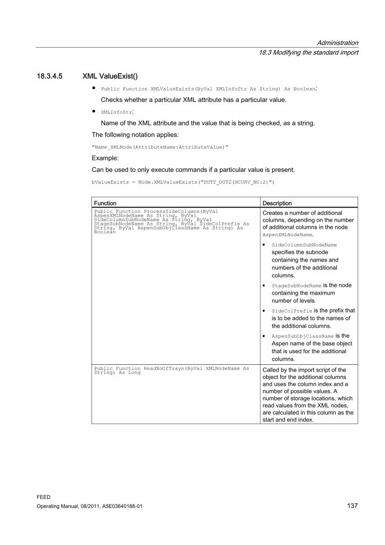
Administration 18.3 Modifying the standard import
FEED Operating Manual, 08/2011, A5E03640188-01 137
18.3.4.5 XML ValueExist() ● Public Function XMLValueExists(ByVal XMLInfoStr As String) As Boolean:
Checks whether a particular XML attribute has a particular value.
● XMLInfoStr:
Name of the XML attribute and the value that is being checked, as a string.
The following notation applies:
"Name_XMLNode(AttributeName:AttributeValue)"
Example:
Can be used to only execute commands if a particular value is present.
bValueExists = Node.XMLValueExists("DUTY_OUT2(HCURV_NO:2)")
Function Description Public Function ProcessSideColumns(ByVal AspenXMLNodeName As String, ByVal SideColumnSubNodeName As String, ByVal StageSubNodeName As String, ByVal SideColPrefix As String, ByVal AspenSubObjClassName As String) As Boolean
Creates a number of additional columns, depending on the number of additional columns in the node AspenXMLNodeName. SideColumnSubNodeName
specifies the subnode containing the names and numbers of the additional columns.
StageSubNodeName is the node containing the maximum number of levels.
SideColPrefix is the prefix that is to be added to the names of the additional columns.
AspenSubObjClassName is the Aspen name of the base object that is used for the additional columns.
Public Function ReadNoOfTrays(ByVal XMLNodeName As String) As Long Called by the import script of the
object for the additional columns and uses the column index and a number of possible values. A number of storage locations, which read values from the XML nodes, are calculated in this column as the start and end index.
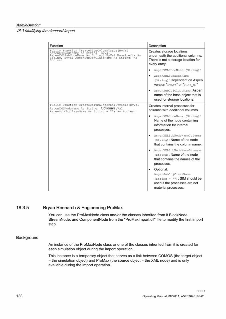
Administration 18.3 Modifying the standard import
FEED 138 Operating Manual, 08/2011, A5E03640188-01
Function Description Public Function CreateSideColumnTrays(ByVal AspenXMLNodeName As String, ByVal AspenXMLSubNodeName As String, ByVal NamePrefix As String, ByVal AspenSubObjClassName As String) As Boolean
Creates storage locations underneath the additional columns. There is not a storage location for every entry. AspenXMLNodeName (String): AspenXMLSubNodeName
(String): Dependent on Aspen version "Stage" or "TRAY_NO"
AspenSubObjClassName: Aspen name of the base object that is used for storage locations.
Public Function CreateColumnInternalStreams(ByVal AspenXMLNodeName As String, OptionalByVal AspenSubObjClassName As String = "") As Boolean
Creates internal processes for columns with additional columns. AspenXMLNodeName (String):
Name of the node containing information for internal processes.
AspenXMLSubNodeNameColumns
(String): Name of the node that contains the column name.
AspenXMLSubNodeNameStreams
(String): Name of the node that contains the names of the processes.
Optional: AspenSubObjClassName
(String = ""): SIM should be used if the processes are not material processes.
18.3.5 Bryan Research & Engineering ProMax You can use the ProMaxNode class and/or the classes inherited from it BlockNode, StreamNode, and ComponentNode from the "ProMaxImport.dll" file to modify the first import step.
Background An instance of the ProMaxNode class or one of the classes inherited from it is created for each simulation object during the import operation.
This instance is a temporary object that serves as a link between COMOS (the target object = the simulation object) and ProMax (the source object = the XML node) and is only available during the import operation.

Administration 18.3 Modifying the standard import
FEED Operating Manual, 08/2011, A5E03640188-01 139
In addition, the import functions defined on the "Script" tab are called for each simulation object during the standard import operation. See also Section Überblick (Page 126). For these calls, the ProMaxNode instance and/or the additional classes inherited from ProMaxNode , which were created for the simulation object, are passed as parameters.
The import calls can be extended and the standard import function for the first import step adjusted using the functions and variables of the ProMaxNode instance.
The "ProMaxImport.dll" file also contains the ProMaxImp class.
This class is instantiated in the OnClick() script of the "BUTTON1Start import" button of the ProMax import object.
Subsequently, the following function of the ProMaxImp instance is called in the script: Sub Import(ByVal devSimulator As IComosDDevice)
This function starts the import operation. A reference to the ProMax import object is transferred as a parameter.
Result of the call: The simulation objects are created underneath devSimulator and an instance of ProMaxNode or one of the classes inherited from it is generated for each simulation object.
18.3.5.1 Public class ProMaxNode The ProMaxNode class is implemented for all simulation objects.
● public IComosDDevice ComosDevice;
Reference to the simulation object whose script is currently being executed.
● public XElement ProMaxXMLNode;
Reference to the current XML source node.
● public string getProMaxXMLNodeName()
Returns the name of the XML node.
Administration 18.3 Modifying the standard import
FEED 140 Operating Manual, 08/2011, A5E03640188-01
18.3.5.2 Public class BlockNode: ProMaxNode The BlockNode class inherits from the ProMaxNode class. The BlockNode class is implemented for all simulation objects to be designated as equipment objects.
● public void createStageObjects()
Creates the trays for a column.
● public void readBlock_Property(string propertyName, string ComosSpecName)
Reads a single value from the properties node of the XML node and writes it to a COMOS attribute.
– Parameter "propertyName"
Type: String
Name of the attribute in the properties node of the XML node
– Parameter "ComosSpecName"
Type: String
Name of the target attribute
● public void readBlockStreamConnections()
Reads out, in the XML node, the streams that are connected to the equipment and enters the data in the list of connectors in the COMOS import data. This method must be called for every equipment simulation object.

Administration 18.3 Modifying the standard import
FEED Operating Manual, 08/2011, A5E03640188-01 141
18.3.5.3 Public class StreamNode: ProMaxNode The StreamNode class inherits from the ProMaxNode class. The StreamNode class is implemented for all simulation objects to be designated as process streams or energy streams.
● public void createSubObjects(string phaseName, string compositionElement, string
propertyName)
Creates the COMOS components for a process stream. The input data is needed to find out how many components there are underneath the process stream.
– Parameter "phaseName"
Type: String
Name of the phase/the phase node in the XML node
– Parameter "compositionElement"
Type: String
Name of the component node in the phase node
– Parameter "propertyName"
Type: String
Name of the attribute in the component node
● public void readPStreamPhase_Property(string phaseName, string propertyName,
string ComosSpecName)
Reads a value out from the XML node and sets this in the COMOS attribute. The value provides more detailed information about an attribute of a specific phase.
– Parameter "phaseName"
Type: String
Name of the phase/the phase node in the XML node
– Parameter "propertyName"
Type: String
Name of the attribute in the phase node
– Parameter "ComosSpecName"
Type: String
Name of the target attribute in COMOS

Administration 18.3 Modifying the standard import
FEED 142 Operating Manual, 08/2011, A5E03640188-01
● public void readStreamConnectionProperties(string connectionType, string specFrom,
string specTo)
Checks, in the XML node, which equipment from which direction is connected to the process stream and writes the result to the COMOS attributes.
– Parameter "connectionType"
Type: String
Name of the connection type in the XML node
– Parameter "specFrom"
Type: String
Name of the target attribute in COMOS if the connection is an incoming connection
– Parameter "specTo"
Type: String
Name of the target attribute in COMOS if the connection is an outgoing connection
● public Boolean existsPhaseType(string typeName)
Checks whether a certain phase is available in the XML node
– Parameter "typeName"
Type: String
Name of the phase type
18.3.5.4 Public class ComponentNode: StreamNode The ComponentNode class inherits from the StreamNode class. The ComponentNode class is implemented for all simulation objects to be designated as process stream components.
● public void readPStreamComposition_Property(string phaseName, string propertyName,
string ComosSpecName)
Reads out, from a phase in the XML node, a value for all components that are available there and writes this value to the relevant COMOS attribute.
– Parameter "phaseName"
Type: String
Name of the phase/the phase node in the XML node
– Parameter "propertyName"
Type: String
Name of the attribute in the phase node
– Parameter "ComosSpecName"
Type: String
Name of the target attribute in COMOS
Administration 18.3 Modifying the standard import
FEED Operating Manual, 08/2011, A5E03640188-01 143
18.3.6 Invensys PRO/II:Class ProIINode The first two import steps can be modified using the ProIINode class from the "Pro2Lib601.dll" file.
Background An instance of ProIINode is created for each simulation object during the import operation. This instance is a temporary object that serves as a link between the target object in COMOS and the source object from Invensys PRO/II and is only available during the import operation.
Analogous to the Aspen Plus import: The import functions defined on the "Script" tab are called for each simulation object in the first two import steps and the ProIINode instance created for this simulation object is transferred as a parameter. See also chapter Überblick (Page 126).
The import calls can be extended by means of the functions and variables of the ProIINode instance, thus modifying the standard import function for the first two import steps.
In the "Pro2Lib601.dll" file, there is also the ProIIComImport class.
This class is initialized in the OnClick() script of the "BUTTON1 Start Import" button of the ProII import object. See also chapter Import objects: Buttons (Page 125). Next, the following function of the ProIICOMImport instance is called in the script:
Function Sub Import(ByVal ObjSimulator As IComosBaseObject):
This function starts the import operation. A reference to the Invensys PRO/II import object is transferred as a parameter.
Result of the call: The simulation objects are created below ObjSimulator and an instance of ProIINode is created for each simulation object.
18.3.6.1 Properties
"ComosDevice" ComosDevice As IComosDDevice
The target object (simulation object).
"Pro2Objects" Pro2Objects As Dictionary
The source objects. These are a collection of Invensys PRO/II objects that each represent an interface of an overall object.
Thus, multiple Invensys PRO/II objects are converted into one COMOS object.
Administration 18.3 Modifying the standard import
FEED 144 Operating Manual, 08/2011, A5E03640188-01
"Pro2File" Pro2File As Object
Reference to the Invensys PRO/II file object from which the data is imported.
For example, if you need more data for the current object than is read by the standard import function.
"Pro2Server" Pro2Server as Object
Reference to the Invensys PRO/II file server. This allows queries to the to be imported file.
"CompCalcDev" CompCalcDev As IComosDDevice
Reference to the CompCalc simulation object, below which the pure components are collected.
"isStream As Boolean" Returns TRUE if the object in question has the Invensys PRO/II class "Stream" or is a temporary stream.
"MaterialCDev As IComosDCDevice" MaterialCDevice As IComosDCDevice
Reference to the base object that is used for all components: "@1PE > PO > SIM > Sub > MAPSIM component simulation object".
"Pro2Components As Collection" Reference to a collection of devices that is located below the CompCalc simulation object.
18.3.6.2 Read() Function Read (ProIIClassName As String, ProIIAttributeName As String, ComosSpecName As String, [index As Integer = -999]) As Boolean
Reads a single value from PRO/II and writes it to an attribute of the COMOS object that is managed by the ProIINode instance.

Administration 18.3 Modifying the standard import
FEED Operating Manual, 08/2011, A5E03640188-01 145
Parameters ● ProIIClassName:
Determines from which in Pro2Objects referenced objects the value is read.
● ProIIAttributeName:
Identifies the source attribute from which the value is read.
● ComosSpecName:
Identifies the target attributes of the object that is referenced in Device.
Notation: NameRegisterkarte.NameAttribut
Since some values in Invensys PRO/IIII do not have a measurement unit, the measurement unit of the output value can also be transferred in the function call. This is done by appending the string /NameComosMaßeinheit to ComosSpecName, where the name of the COMOS measurement unit is passed exactly as it was defined in the COMOS unit system.
Example:
Unit group molar volume: Name M62
Unit: Cubic meter/Kilomol, Name: M62.25
Parameter ComosSpecName: SPH.CD0199/M62.25
● index:
Optional. Enables to read a value from an array.
Example:
Node.Read "SrBulkProp", "SolidCritVolume", "SPH.CD0199/M62.25"
18.3.6.3 ReadArray() Function ReadArray(ProIIClassName As String, ProIIArrSizeAttributeName As String, ProIIAttributeName As String, ComosSpecName As String) As Boolean
Reads a one-dimensional data field from Invensys PRO/II and writes it to a list attribute in COMOS.
Parameters ● ProIIClassName:
Identifies the object from whose source data field values are read.
● ProIIArrSizeAttributeName:
Specifies the name of the attribute that contains the size of the source data field.
Empty string: No size is passed.
Administration 18.3 Modifying the standard import
FEED 146 Operating Manual, 08/2011, A5E03640188-01
● ProIIAttributeName:
Identifies the source data field.
● ComosSpecName:
Analogous to Read(). The attribute must be of type List. The name of the column into which the data field is written must be passed as well.
Notation: "NameOfTab.NameOfAttribute.NameOfColumn"
Example:
Node.ReadArray "SideColumn", "NumberOfPumparounds", "PumpAroundTrayFrom",
"TPA.ND0081.ND0072" 'Pumparound from tray
18.3.6.4 ReadArrayToFewSpecs() Function ReadArrayToFewSpecs (ProIIClassName As String, ProIIArrSizeAttributeName As String, ProIIAttributeName As String, ComosSpecNames As String) As Boolean
Reads a one-dimensional data field from Invensys PRO/II and writes it to multiple attributes of the COMOS object that is managed by the ProIINode instance.
Parameters ProIIClassName, ProIIArrSizeAttributeName und ProIIAttributeName:
As ReadArray().
ComosSpecNames:
Contains the names of the target attributes. They are passed in a string, separated by commas.
This function is used if values are stored in one data field in Invensys PRO/II and distributed over two data fields in COMOS.
Example:
Node.ReadArrayToFewSpecs "HcurveCalc", "NumberOfPoints","CriticalPresLV",
"HC.ND0114.CD0015v, HC.ND0114.CD0015l/P11.32"' Critical Pressure
18.3.6.5 ReadSI() Function ReadSI (ProIIClassName As String, ProIIAttributeName As String, [index As Integer = -999]) As Double
Returns the value of an attribute from Invensys PRO/II as a numeric value. The function is called if you need the value within control flow structures, for example.

Administration 18.3 Modifying the standard import
FEED Operating Manual, 08/2011, A5E03640188-01 147
There are differences between Invensys PRO/II and COMOS with regard to the use of SI standardization. If there is a difference, the COMOS SI standardization is used as a basis. This means that the value is converted from the unit specified by the Invensys PRO/II standardization into the unit specified by the COMOS standardization.
Parameters See also chapter Read() (Page 144).
18.3.6.6 GetComosSpecArray() Function GetComosSpecArray(ComosSpecNames As String, ComosSpecCount As Integer) As String()
Help method.
Parameters ● ComosSpecNames As String:
Comma-separated list of COMOS attributes.
● ComosSpecCount As Integer:
Number of attributes that are passed in ComosSpecNames.
Return value:
String Array: Each field contains one of the attribute names that were passed in ComosSpecNames.
18.3.6.7 Intern verwendete Funktionen ProIINode owns additional functions that are only called internally and which have no application in the modification of the import.
"ReadMainComp()" Function ReadMainComp (ProIIClassName As String, ProIIAttributeName As String, ComosSpecName As String, [index As Integer = -999]) As Boolean
Reads a value from Invensys PRO/II and writes it to a subobject (component) of the CompCalc engineering object.
Parameters See also chapter Read() (Page 144).

Administration 18.3 Modifying the standard import
FEED 148 Operating Manual, 08/2011, A5E03640188-01
"ReadStreamComp()" Function ReadStreamComp (ProIIClassName As String, ProIIAttributeName As String, ComosSpecName As String, [index As Integer = -999]) As Boolean
Writes data to a component link below a material stream. The component link is created, if it does not already exist. The created objects are based on the base object "@1PE > PO > SIM > SUB > MAPSIM".
"ReadTempStream()" Function ReadTempStream(StreamID As String)
It is possible to create virtual streams in Invensys PRO/II. A call to this function imports a virtual stream to COMOS.
First, the stream is created in COMOS below the calling object. Then, the data is imported in the same way as for a normal material stream.
"ReadTrayStreams()" Sub ReadTrayStreams()
If this function is called at a column, an object with name prefix "Tray" is created below the column for each tray.
The created objects are instances of the base object "@1PE > PO > SIM > SUB > TRSIM".
18.3.7 AspenTech HYSYS: Class HYSYSNode The first two import steps can be modified using the HYSYSNode class from the "HYSYSImport.dll" file.
Background An instance of HYSYSNode is created for each simulation object during the import operation. This instance is a temporary object that serves as a link between COMOS (the target object) and AspenTech HYSYS (the source object) and is only available during the import operation.
The import functions defined on the "Script" tab are called for each simulation object in the first two import steps and the HYSYSNode instance created for this simulation object is transferred as a parameter. See also chapter Überblick (Page 124).
The import calls can be extended via the functions and variables of the HYSYSNode instance and the standard import function modified for the first two import steps.
In the "HYSYSImport.dll" file, there is also the HYSYSImport class.
This class is initialized via the OnClick() script of the "BUTTON1 Start Import" button of the AspenTech HYSYS import object. See also chapter Import objects: Buttons (Page 125). Subsequently, the following function of the HYSYSImport instance is called in the script:
Administration 18.3 Modifying the standard import
FEED Operating Manual, 08/2011, A5E03640188-01 149
Sub Import(ByVal objSimCase As IComosBaseObject)
This function starts the import operation. A reference to the AspenTech HYSYS import object is transferred as a parameter.
Result of the call The simulation objects are created below objSimCase and an instance of HYSYSNode is created for each simulation object.
18.3.7.1 Properties
"ComosDevice" ComosDevice As IComosDDevice
The target object in COMOS.
"Components" Components As Object
Link to the components of the active FluidPackage from AspenTech HYSYS.
"HYSYSObject" HYSYSObject As Object
The source object.
"NodeType" NodeType As eNodeType
Only used internally. Variable to identify the AspenTech HYSYS types.
"SpecLog" SpecLog As IComosDSpecification
Reference to the "ND0122" attribute at the import object, to which the log text is written.
The property is used to control the output during the import operation.
"XPos" XPos As Double
X coordinate of the object in the AspenTech HYSYS PFD.

Administration 18.3 Modifying the standard import
FEED 150 Operating Manual, 08/2011, A5E03640188-01
"YPos" YPos As Double
Y coordinate of the object in AspenTech HYSYS PFD.
18.3.7.2 HYSYSClass() Function HYSYSClass() As String
Reads the HYSYS class name from HYSYSObject.
18.3.7.3 LiquidPhase1() Function LiquidPhase1() As Object
Call at simulation material streams.
If HYSYSObject involves a stream, this function returns the LiquidPhase1 object of the HYSYS stream. The phase data can be read from the object.
18.3.7.4 LiquidPhase2() Function LiquidPhase2() As Object
See also section LiquidPhase1() (Page 150).
18.3.7.5 Read() Function Read(strSpecName As String, hyAttribute As Variant, [strHYSYSUnit As
String], [strParam As String])
Reads a single value from HYSYS and writes it to an attribute of the COMOS object managed by HYSYSNode.
● strSpecName:
Target attribute
● hyAttribute:
The HYSYS object.
● strHYSYSUnit:
Optional
The value that is passed here is set as SI unit. Then the value is converted into the unit that was set for the target attribute.
If a number is passed: The value of the HYSYS object is multiplied by this factor.
Blank: The default unit for this HYSYS object type is determined and used.
● strParam:
Optional
If the target attribute is a list. The index for setting the XValue.

Administration 18.3 Modifying the standard import
FEED Operating Manual, 08/2011, A5E03640188-01 151
18.3.7.6 ReadPhase Sub ReadPhase(strchapter As String, hyFluidPhase As Object)
Call at simulation stream objects. Writes phase tabs to streams.
hyFluidPhase:
For example, by calling LiquidPhase1().
18.3.7.7 VapourPhase() Function VapourPhase() As Object
See also section LiquidPhase1() (Page 150).
18.3.8 Honeywell UniSim Design: Class UniSimNode The modification made for the UniSim import corresponds to the modifications made for HYSYS; the only difference is the name.
See also AspenTech HYSYS: Class HYSYSNode (Page 148)
18.3.9 Evonik EbsilonProfessional: Class EbsilonNode The first two import steps can be modified using the EbsilonNode class from the "ComosEbsilonImport.dll" file.
Background An instance of the EbsilonNode class is created for each simulation object during the import operation. This instance is a temporary object that serves as a link between the target object in COMOS and the source object in Evonik EbsilonProfessional and is only available during the import operation.
The import functions defined on the "Script" tab are called for each simulation object during the first two import steps. The instance of EbsilonNode that was created for the simulation object is transferred as a parameter. See also chapter Überblick (Page 124).
The import calls can be extended by means of the functions and variables of the EbsilonNode instance, thus modifying the standard import function for the first two import steps.
In the "ComosEbsilonImport.dll" file, there is also the EBSILONImport class. This class is initialized via the OnClick() script of the "BUTTON1 Start Import" button of the Ebsilon import object. See also chapter Import objects: Buttons (Page 125). Next, the following function of the EBSILONImport instance is called in the script:
Administration 18.3 Modifying the standard import
FEED 152 Operating Manual, 08/2011, A5E03640188-01
Sub Import(ByVal objSimCase As IComosBaseObject)This function starts the import operation. A reference to the Ebsilon import object is transferred as a parameter.
Result of the call The simulation objects are created below objSimCase and an instance of EbsilonNode is created for each simulation object.
18.3.9.1 Properties
"ComosObject" ComosDevice As IComosDDevice
The target object in COMOS.
"ebsObject" EbsilonObject As ebsOpen.Object
The source object.
18.3.9.2 GetEbsKind() Function GetEbsKind () As String
Reads the Ebsilon class name from ebsObject.
18.3.9.3 Read()
Script Function Read (ByVal ebsAttribute As String, Optional ByVal strSpecName As String, Optional ByVal SpecListIndex As Long = -1, Optional ByVal strParam As String = "") As String
Reads a single value from Evonik EbsilonProfessional and writes it to an attribute of the COMOS object managed by EbsilonNode.
Script Description ebsAttribute Target attribute: If no name is specified, the value is simply returned. Writing
does not take place. SpecListIndex Optional: If the target attribute is a list attribute.

Administration 18.3 Modifying the standard import
FEED Operating Manual, 08/2011, A5E03640188-01 153
Script Description strParam Optional: Only strvalue is processed as a possible transfer value. If this is
set, the .StringValue rather than the Value of the Ebsilon attribute is returned.
strSpecName Optional: Target attribute: If no name is specified, the value is simply returned. Writing does not take place.
18.3.9.4 ReadNumeric()
Script Function ReadNumeric (ByVal ebsAttribute As String, Optional ByVal strSpecName As String, Optional ByVal SpecListIndex As Long = -1, Optional ByVal strParam As String = "") As Double
Script Description ebsAttribute Name of the attribute to be read out strSpecName Optional: Target attribute: If no name is specified, the value is simply
returned. Writing does not take place. SpecListIndex Optional: If the target attribute is a list attribute. strParam Optional: Not currently used.
18.3.10 Chemstations ChemCad: Class ChemCad Node The first two import steps can be modified using the ChemCadNode class from the "ComosChemCadImport.dll" file.
Background An instance of the ChemCadNode class is created for each simulation object during the import operation. This instance is a temporary object that serves as a link between the target object in COMOS and the source object from ChemCad and is only available during the import operation.
The import functions defined on the "Script" tab are called for each simulation object during the first two import steps. The instance of ChemCadNode that was created for this simulation object is transferred as a parameter. See also chapter Überblick (Page 124).
The import calls can be extended by means of the functions and variables of the ChemCadNode instance, thus modifying the standard import function for the first two import steps.
In the "ComosChemCadImport.dll" file, there is also the CHEMCADImport class. This class is initialized via the OnClick() script of the "BUTTON1 Start Import" button of the Chemstations ChemCad import object. See also chapter Import objects: Buttons (Page 125). Next, the following function of the CHEMCADImport instance is called in the script:
Administration 18.3 Modifying the standard import
FEED 154 Operating Manual, 08/2011, A5E03640188-01
Sub Import(ByVal objSimCase As IComosBaseObject)
This function starts the import operation. A reference to the CHEMCADImport object is transferred as a parameter.
Result of the call The simulation objects are created below objSimCase and an instance of ChemCadNode is created for each simulation object.
18.3.10.1 Properties
"ComosDevice" ComosDevice As IComosDDevice
The target object in COMOS.
"StreamComponents" Components As Object
Reference to the components of the active FluidPackage from Chemstations ChemCad.
"NodeType" NodeType As eNodeType
Variable that identifies the ChemCad type and is only used internally.
"SpecLog" SpecLog As IComosDSpecification
Reference to the "ND0122" attribute at the import object, to which the log text is written. This property is used to control the output during the import operation.
"UnitOp Type" Enumeration for the type of Unit Operation / Equipment
18.3.10.2 GetChemCadClass() Function GetChemCadClass () As String
Returns the CHEMCAD class name of the object.
18.3.10.3 ReadNumeric()
Script Function ReadNumeric

Administration 18.3 Modifying the standard import
FEED Operating Manual, 08/2011, A5E03640188-01 155
(ByVal ccAttribute As String, ByVal strSpecName As String, ByVal Unit As String, Optional ByVal SpecListIndex As Long = -1, Optional ByVal StreamID As Integer = -1, Optional ByVal strParam As String = "") As Double
Reads a single value from Chemstations ChemCad and writes it to an attribute of the COMOS object managed by ChemCadNode.
Script Description ccAttribute Source attribute in Chemstations ChemCad strSpecName Target attribute in COMOS Unit Target unit in unit conversion SpecListIndex Optional: Only if the target attribute is a list.
The index for setting the XValue. StreamID Optional: Required for reading out values for components below a
stream. strParam Optional: Not currently used.
18.3.10.4 ReadEquilibriumReactionPar()
Script Function ReadEquilibriumReactionPar (ByVal ccAttribute As String, ByVal strSpecName As String, ByVal Unit As String, ByVal ReactionNo As Integer, ByVal CompID As Integer, Optional ByVal SpecListIndex As Long = -1) As Double
Special case for equilibrium reactions. See also section ReadNumeric() (Page 154).
18.3.10.5 ReadStreamComponents Function ReadStreamComponents() As Long
Accesses components at a stream one by one and executes the script for components for each one.
18.3.10.6 FillTrayStreamList Function FillTrayStreamList()
Reads the input and output streams of a column and writes them, together with their corresponding tray numbers, to the SImObject of the column.

Administration 18.3 Modifying the standard import
FEED 156 Operating Manual, 08/2011, A5E03640188-01
18.3.11 Default settings for the simultaneous import of multiple files A link to the PF template to be used for the PF equipment and PF process streams (import steps 3 and 4) must be set up in the import options for the "Batch Import Control Center" object.
A link to a suitable PF template is set by default. You can view this default setting and link a different PF template, if required.
Procedure 1. In the "Base objects" tab in the Navigator, open the "@1PE > PO > SIM > XXSI
Simulation import objects" node.
2. Open the properties of the "BICCBatch Import Control Center" object. Go to the "Attributes > Import options" tab.
The link to the PF template is displayed in the "Link to PF template" field.
3. If required, click the "..." button and select a different PF template in the "Link to PF template" field.
4. Save your entries once you have made the changes.
18.3.12 Setting margins for automatic placing of equipment on reports
Application area To keep space free for a logo or other design elements on reports, in the standard import, you can set margins for the automatic placing of equipment on reports. This is entirely independent of the type of simulator used.
These settings are used when placing equipment automatically. See also Section Import step 3: Place the equipment on the PF (Page 50).
Procedure 1. Margins for the automatic placing of equipment on reports can be set in the following
ways:
– To make a change that is to be applied for just one report, select a report "PF process diagram" on the "Units" tab.
– To make basic settings for a certain type of report, create a copy of the corresponding base object on the "Base objects" tab and make your changes.
You can find additional information on this topic in the "Document management" manual and in the "Reports - Basic Operation" manual.
2. Open the properties of the required report.
3. Go to the "Attributes > Document options" tab.
4. Deactivate the "Standard margin placement" option.

Administration 18.3 Modifying the standard import
FEED Operating Manual, 08/2011, A5E03640188-01 157
5. Make your entries for the coordinate system of the report in the "Left and right margin" and "Top and bottom margin" fields.
6. Save your entries.
18.3.13 Settings for importing unknown simulation objects Objects that are unknown to COMOS can be imported with attributes, values, and units in dummy objects. This function is supported by various simulators. See also Section Basic principles (Page 52).
Users define whether they wish to import dummy simulation objects. See also Section Importing wildcard objects (Page 53).
By default, all simulation objects found are imported when unknown simulation objects are imported. As the administrator, you can define simulation types that are not to be imported.
Procedure 1. Open the "@1PE > PO > SIM > BLC > DUMMYSIMDummy simulation object" node on
the "Base objects" tab.
2. Open the properties of the "DUMMYSIMDummy simulation object" object and go to the "Attributes > Import data" tab.

Administration 18.4 Assemblies
FEED 158 Operating Manual, 08/2011, A5E03640188-01
3. Enter the simulation types that are not to be imported in the field bearing the name of the simulator concerned. To enter more than one simulation type in a field, you must enter the types separated by a comma ",".
4. Save your entries.
18.4 Assemblies
18.4.1 Allgemeines zu Baugruppen Assemblies are also called templates and consist of conventional COMOS engineering objects. There are various benefits to using assemblies. You can find additional information on this topic in the "COMOS Administration" manual, keyword "Templates/assemblies".
Sole precondition for assemblies: The objects have to be organized in a certain way. See also section Creating P&ID assemblies (Page 159).

Administration 18.4 Assemblies
FEED Operating Manual, 08/2011, A5E03640188-01 159
18.4.2 Creating P&ID assemblies
18.4.2.1 Creating the unit as a collection folder for P&ID objects
Procedure To create a unit as a collection folder for P&ID objects, proceed as follows:
1. Open the base project.
2. In the Navigator, expand the "@Template Copy templates" node on the "Units" tab.
3. Expand the "PE Process Engineering" folder.
The "PE Process Engineering" folder contains a "02 P&ID Templates" node consisting of different types of equipment folders:
4. Select the appropriate subfolder based on the required type.
5. Create a PFD object via the "New" context menu.
Example There follows an example of how to create a new assembly for a vertical vessel:
1. Expand the "02 Vessel" node.
2. Right-click the "01 Vertical vessel" subfolder and select the context menu command "New > New object".
3. Assign an appropriate base object to the object you have just created. Appropriate base objects are located in node "@1PE > PO > EQ". For a vertical vessel, for example, select the base object "@1PE > PO > EQ > 03 > VES > VES01 Vessel, vertical" and drag it to the "Base object" field in the properties of the object you have just created.
This creates an engineering object.
4. If necessary, rename the unit "@PEASSEMBLY".
18.4.2.2 Verknüpfen der DimLen- und PFD-Objekte
Linking the DimLen objects to PFD objects If you have grouped objects using a DimLen object, you can link the attributes of the single objects and link the attributes of the DimLen group with PFD attributes. You use the "XV002" attribute to do so.
Example for linking the length of a DimLen object with a PFD attribute 1. Set the PFD attribute as the source attribute.
2. Set "XV002" as the target attribute.
Administration 18.4 Assemblies
FEED 160 Operating Manual, 08/2011, A5E03640188-01
18.4.2.3 Connector mapping Link the PFD and P&ID connectors in order to enable correct conversion of a PFD to a P&ID. The P&ID connectors mainly belong to nozzles.
PFD-Anschlüsse auf R&I-Anschlüsse abbilden
Procedure To map PFD connectors to P&ID connectors, proceed as follows:
1. Open the properties of the "@PEASSEMBLY" object.
2. Click the "PFD / PID Connector Mapping" tab.
Each of the "I" and "O" fields on the tab represents a particular PFD object connector.
3. Drag the nozzle of the P&ID object to the relevant "I" or "O" field on the "PFD / PID Connector Mapping" tab.
As a general rule, P&ID objects do not directly have connectors, but they are located on the nozzle elements. Unlike PFD connectors, nozzles usually need to be placed on the P&ID object before being able to access the P&ID connectors.
The additional connector fields "001" to "014" are available for user-defined or automatically generated connectors. They can be used in the same way as the "I" and "O" fields.
4. Click "OK" to save.
To make the new assembles available to all users, please also refer to section Availability of P&ID assemblies (Page 161).
18.4.2.4 R&I-Baugruppen erstellen P&ID assemblies are used to convert PFD objects into P&ID objects.
Procedure 1. Create the "@PEASSEMBLY" object as a collection folder for the P&ID objects. See also
section Creating the unit as a collection folder for P&ID objects (Page 159).
2. Expand the "@PEASSEMBLY" node.
3. Open the "PID P&ID Template" document.
4. Build a P&ID group by means of the symbol bars. The base objects of the branch "PI > PI EN Piping and Instrumentation" can also be used.
5. Switch to the Navigator and move the objects that have automatically been created next to the P&ID document so that they are under the "PID P&ID Template" document.
6. Save the P&ID template.
7. Link the PFD and P&ID connectors in the same way as described in section Connector mapping (Page 160).
Administration 18.4 Assemblies
FEED Operating Manual, 08/2011, A5E03640188-01 161
18.4.3 Availability of P&ID assemblies After you have created the P&ID assemblies, they need to be made available to all users. They can be accessed from the context menu of the PFD objects, for example.
Procedure To make the assemblies available, proceed as follows:
1. Open the "Base objects" tab in the base project.
2. Select the base object of the relevant PFD engineering object in the "@1PE > PO > EQ Equipment" branch.
3. Create a query below the relevant PFD base object that you can use to find and filter assemblies.
The query must be assigned the name "@Templatelist".
4. Open the query and assign suitable base and start objects as search parameters.
18.4.4 Baugruppen aus Baugruppen erstellen
Procedure You can also use existing assemblies as templates for new assemblies. In order to create an assembly for a horizontal vessel, you can use another vessel assembly as a template:
1. Click the "Units" tab in the base project.
2. Expand the "@Template > PE > 02 > 02 > 01 Vertical vessel" node.
In folder "01 Vertical vessel" you will find the "VES002 Vertical vessel" object.
3. Copy this object and paste it into the same folder.
4. Expand the "@PEASSEMBLY" node.
5. If the copied assembly has been checked, there are two available paths:
– Delete all objects under the node "@PEASSEMBLY Vessel, vertical". Create a completely new group by placing new objects and grouping them with the DimLen objects.
– Delete specifically those objects you no longer need and add more objects. Then create a new DimLen group.
6. Create links between the PFD and P&ID connectors by means of a mapping table, as described in section Verknüpfen der DimLen- und PFD-Objekte (Page 159).
If a mapping table already exists in an assembly, then no other can be created; exactly this one has to be used.
Administration 18.4 Assemblies
FEED 162 Operating Manual, 08/2011, A5E03640188-01
18.4.5 The PE Base object structure
18.4.5.1 PE-Hauptknoten On the "Base objects" tab in the base project, you will find the root node for PE objects under "@1PE > Process Objects", which is subdivided into the following categories:
● "DS"
● "PO"
● "US"
18.4.5.2 "DS Data Structure" This node mainly contains the attribute and tab catalogs for designing the actual PE base objects.
"@Y Attributes catalog" All attributes used in the PE module are in this node in order to ensure unique naming. Furthermore, they function as catalog attributes, in order for them to be only changed here once, and not after every use.
Attributes of subordinate nodes Node Description "CD Chemical and physical data" Contains numerical attributes with or without a unit "ND Names, Descriptions, Numbers" For text attributes such as text fields, remarks, and
descriptions "SY System Attributes" Contains special system attributes that should not be
changed "Q1 Query: CD" Provides a quick search function to, for example, find
attributes according to their description or unit "Q2 Query: ND" Same as Q1, but for the ND node
"CC Tabs Catalog" All tabs that are in the PE module are located in this node. First create the tabs as a template to ensure that the names are unique within the categories.
The tabs for PE objects (e.g. Equipment, Process, Process Unit, Material Stream) are divided into object-specific categories.
"CEQ > CREM Tab Remarks" Base object for remark attributes

Administration 18.4 Assemblies
FEED Operating Manual, 08/2011, A5E03640188-01 163
MT Verknüpfungstabellen Mapping tables for equipment, material streams and pipes are contained here.
● MTQE: Mapping tables between simulation equipment and PFD equipment.
● MTMS: Mapping tables between simulation material streams and PFD material streams.
● MTPI: Mapping tables between process streams.
"QU Queries" This node contains queries for attributes, documents, and engineering objects.
18.4.5.3 "PO Process Objects" This node contains all equipment objects, simulation objects, and stream objects for the PE module.
"EQ Equipment" This node contains all base objects for PFD equipment.
"SIM Simulation Objects" This node contains all base objects for simulation objects, divided into "BLC Equipment Simulation Objects", "STR Stream Simulation Objects", "SUB Simulation Subobjects", and "XXSI Simulation Import Objects":
Node Description "BLC Equipment Simulation Objects" Base objects for all general simulation objects such as
columns, armatures, heat exchangers, pumps, reactors etc.
"STR Stream Simulation Objects" Base objects for simulation streams and CompCal for components
"SUB Simulation Subobjects" Base objects for simulation subobjects "XXSI Simulation Import Objects" Base object for the Aspen import simulation object
See also chapter "@1PE > PO > SIM Simulation Objects" (Page 165).
"SO Stream Objects" The "SO Stream Objects" node contains base objects for process streams and material streams and their components, e.g. component pointers and pure components. Also the base object for block diagrams as e.g. balance streams, balance stream flags, Input/Output arrows and process units.
18.4.5.4 "US Unit System" It contains the predefined unit structure of the PE module.

Administration 18.4 Assemblies
FEED 164 Operating Manual, 08/2011, A5E03640188-01
18.4.6 Tips for administrators on PE objects
18.4.6.1 Tipps für Verfahrenseinheiten To ensure that the process units in the block diagram are automatically added to the "APU Process Units" folder of the process, the following conditions must be fulfilled:
● In the base project, activate the "Subelements" option on the "System" tab for the subnode of the "@1PE > US > FI > PR Process" base object.
Note that the base object whose "Subelements" mode is activated is the base object under which the block diagram is located.
● "APU Process Units" folder: Activate the "Subelements" creation mode here too.
● For the subfolders of the "@1PE > US > FI > PR Process" base object, select the "Unit" class and "Category" subclass on the "System" tab.
● The process unit must be an element of the "APU Process Unit" folder.
● In the Options script block of the report template of the block diagram the term SortNewObjectsInCategories = True must be available.
18.4.6.2 Tipps für Bilanzströme The base object for balance streams is "@1PE > PO > SO > BS Balance Stream", and the base object for flags is "@1PE > PO > SO > BSF Balance Stream Flag".
18.4.6.3 Verknüpfungen von Equipment-Attributen kontrollieren The links between the maximum and minimum temperature and pressure as well as between the data on the "Design Data" tab and the data of the connected stream can be controlled as follows:
Script function GetDisplayValue() of the attributes CD0123, CD0124, CD0125, and CD0126.

FEED Operating Manual, 08/2011, A5E03640188-01 165
Base data reference 19
The base objects that are relevant for the interfaces are located on the "Base objects" tab, under the "@1PE Process Engineering" branch.
Structure of the "@1PE Process Engineering" node The following table describes the structure of the "@1PE Process Engineering" node:
Subordinate node Description "DS Data Structures" Under this node you will find:
Document base objects Attributes and tabs catalog Project structure nodes for preparation of the planning
structure. See also Section Creating and grouping pure components under the "AMA" folder (Page 189).
"PO Process Objects" Under this node you will find: Equipment Stream objects Case objects Objects for the interface import
"US Unit System" Under this node you will find categories for the automatic sorting of objects in the planning structure. You can find additional information on this topic in the "COMOS Administration" manual, keyword "Categories".
19.1 "@1PE > PO > SIM Simulation Objects"
Objective The base objects for the simulation objects that are created in the first import step must be located in the "@1PE > PO > SIM" branch. It is not permitted to change the name of the branch.
If you want to create your own branch of simulation objects, it must have the name "@1PE > PO > SIM". Rename the branch supplied in the COMOSDB.

Base data reference 19.1 "@1PE > PO > SIM Simulation Objects"
FEED 166 Operating Manual, 08/2011, A5E03640188-01
Structure The following structure objects are located on the first level underneath the "@1PE > PO > SIM" node:
● "@1PE > PO > SIM > BLC Equipment Simulation Objects"
● "@1PE > PO > SIM > STR Stream Simulation Objects"
● "@1PE > PO > SIM > SUB Simulation Subobjects"
● "@1PE > PO > SIM > XXSI Simulation Import Objects"
The actual simulation objects are located underneath the structure objects.
See also "@1PE > PO > SIM > BLC Equipment Simulation Objects" (Page 168)
"@1PE > PO > SIM > STR Stream Simulation Objects" (Page 170)
"@1PE > PO > SIM > SUB Simulation Subobjects" (Page 171)
"@1PE > PO > SIM > XXSI Simulation Import Objects" (Page 173)
19.1.1 Eigenschaften der Simulationsobjekte Since the base objects below "@1PE > PO > SIM" are simulation objects, their names end with the "SIM" syllable. This naming is optional and is used solely to provide better orientation within the base data.
"ID Import data" tab The simulation objects that are located below the structure objects all have the "Import data" tab. The tab has the following attributes:
Attribute Name Description "Aspen name" "ND0056" "ProII name" "ND0057" "HYSYS name" "ND0790"
Specifies which class from the simulator the base object is assigned to. The simulation object is assigned to the object from the source file on the basis of the value entered here. The attributes can contain multiple designators, separated from one another by commas and without blank spaces. The spelling of the designator must be identical to the one used in the simulator.
"Relative path" "ND0058" Specifies where the associated PFD object is to be created in the second import step. During an import from a simulator, the PFD objects are always created as specified at the import object, in the "Pure components", Equipment", and "Process streams" fields on the "Import options" tab. See also chapter "@1PE > PO > SIM > XXSI Simulation Import Objects" (Page 173).

Base data reference 19.1 "@1PE > PO > SIM Simulation Objects"
FEED Operating Manual, 08/2011, A5E03640188-01 167
Attribute Name Description " "PFD object" "ND0059" Is automatically set during the second import step. References
the PFD object that is created in the second import step for this simulation object.
"CDevice" "ND0060" Determines which base object is to be used to create a PFD object for the simulation object. See also chapter "@1PE > PO > SIM > STR > CCSIM CompCalc Simulation Object" (Page 170).
The "@1PE > PO > SIM > BLC" node supplements the "Import data" tab inherited from "@1PE > PO > SIM" with additional attributes. See also chapter "@1PE > PO > SIM > BLC Equipment Simulation Objects" (Page 168).
"SYS System" tab The "Object class" attribute stores object classes using the "@1PE > SYS > SY0001" standard table. The attribute is not evaluated during the import operation. You can use it in scripts for internal purposes; for example, when making a search for all objects of a particular class.
Inheritance source of the attributes Most attributes are inherited directly from the "@1PE > DS > @Y" attributes catalog. However, tabs from the catalog are also used, and in some cases the inherited tabs are extended as well.
Edit mode of the attributes The following applies for the attributes of the "SIM" node:
As a rule, attributes whose values are imported from the simulator have the edit mode "Values in XML (Limited functionality)". This edit mode is not absolutely essential, but it should be selected so that the data can be imported more quickly.
Functionality of the attribute This mode restricts the functionality of the attribute (for example, linking is no longer possible).
You can find additional information on this topic in the "System type properties" manual, under "Values in XML (Limited functionality)".
Scripts Each object below the "@1PE > PO > SIM" node defines functions on the "Script" tab that determine what is to be done with this object during the first and second import steps.
In the COMOSDB, there is a command in the functions that calls the standard import function. This call should not be deleted. However, the functions can be extended with commands of their own and the standard import operation is thus modified.
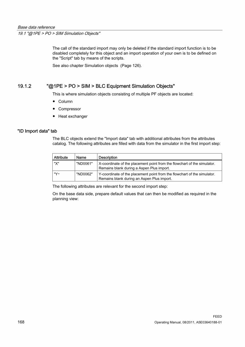
Base data reference 19.1 "@1PE > PO > SIM Simulation Objects"
FEED 168 Operating Manual, 08/2011, A5E03640188-01
The call of the standard import may only be deleted if the standard import function is to be disabled completely for this object and an import operation of your own is to be defined on the "Script" tab by means of the scripts.
See also chapter Simulation objects (Page 126).
19.1.2 "@1PE > PO > SIM > BLC Equipment Simulation Objects" This is where simulation objects consisting of multiple PF objects are located:
● Column
● Compressor
● Heat exchanger
"ID Import data" tab The BLC objects extend the "Import data" tab with additional attributes from the attributes catalog. The following attributes are filled with data from the simulator in the first import step:
Attribute Name Description "X" "ND0061" X-coordinate of the placement point from the flowchart of the simulator.
Remains blank during a Aspen Plus import. "Y" "ND0062" Y-coordinate of the placement point from the flowchart of the simulator.
Remains blank during an Aspen Plus import.
The following attributes are relevant for the second import step:
On the base data side, prepare default values that can then be modified as required in the planning view:
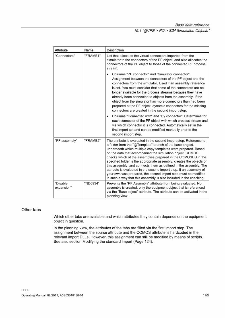
Base data reference 19.1 "@1PE > PO > SIM Simulation Objects"
FEED Operating Manual, 08/2011, A5E03640188-01 169
Attribute Name Description "Connectors" "FRAME1" List that allocates the virtual connectors imported from the
simulator to the connectors of the PF object, and also allocates the connectors of the PF object to those of the connected PF process stream. Columns "PF connector" and "Simulator connector":
Assignment between the connectors of the PF object and the connectors from the simulator. Used if an assembly reference is set. You must consider that some of the connectors are no longer available for the process streams because they have already been connected to objects from the assembly. If the object from the simulator has more connectors than had been prepared at the PF object, dynamic connectors for the missing connectors are created in the second import step.
Columns "Connected with" and "By connector": Determines for each connector of the PF object with which process stream and via which connector it is connected. Automatically set in the first import set and can be modified manually prior to the second import step.
"PF assembly" "FRAME2" The attribute is evaluated in the second import step. Reference to a folder from the "@Template" branch of the base project, underneath which multiple copy templates were prepared. Based on the data that accompanied the simulation object, COMOS checks which of the assemblies prepared in the COMOSDB in the specified folder is the appropriate assembly, creates the objects of this assembly, and connects them as defined in the assembly. The attribute is evaluated in the second import step. If an assembly of your own was prepared, the second import step must be modified in such a way that this assembly is also included in the checking.
"Disable expansion"
"ND0934" Prevents the "PF Assembly" attribute from being evaluated. No assembly is created, only the equipment object that is referenced via the "Base object" attribute. The attribute can be activated in the planning view.
Other tabs Which other tabs are available and which attributes they contain depends on the equipment object in question.
In the planning view, the attributes of the tabs are filled via the first import step. The assignment between the source attribute and the COMOS attribute is hardcoded in the relevant import DLLs. However, this assignment can still be modified by means of scripts. See also section Modifying the standard import (Page 124).

Base data reference 19.1 "@1PE > PO > SIM Simulation Objects"
FEED 170 Operating Manual, 08/2011, A5E03640188-01
19.1.3 "@1PE > PO > SIM > STR Stream Simulation Objects"
Structure of the node: ● "@1PE > PO > SIM > STR > CCSIM CompCalc Simulation Object"
● "@1PE > PO > SIM > STR > MSSIM Material stream simulation object"
19.1.3.1 "@1PE > PO > SIM > STR > CCSIM CompCalc Simulation Object" Base object for the simulation object below which the pure components are collected in the planning view in the first import step.
Specialty in comparison with the other simulation objects:
● "ID Import data" tab > "ND0060 CDevice"attribute:
Value: "@1PE > PO > SO > MAS > MA0000 Component"
The simulation pure components are created below the CCSIM object in the first import step. The base object "@1PE > PO > SO > MAS > M0000 Component" from the pure components library is always used as the base object for the simulation pure components. See also chapter "@1PE > PO > SO > MAS Pure Components" (Page 182).
However, the CCSIM object can also be used outside the automated interface import. Since no PFD counterpart is required for the CompCalc simulation object in the second import step, you enter which base object is to be used for the simulation pure components here.
For that reason the attribute must be editable, even if a manual change is not taken into consideration during an interface import operation.
● "ID Import data" tab > "ND0059 PFD object" attribute:
Since no PFD object is created for the simulation object in the second import step, the attribute remains blank.
19.1.3.2 "@1PE > PO > SIM > STR > MSSIM Material Stream Simulation Object" This is the base object of the simulation objects for material streams that are created in the first import step.
Only the case-specific data of the process streams is imported from the simulator. In COMOS, this data is stored in material stream objects. The components are located below each material stream, hence the components that contain the component data of the case.
Import of the main case Multiple PFD objects are created during the second import step for each MSSIM object:
● PFD process stream
● PFD material streams for the imported case as well as for the default cases
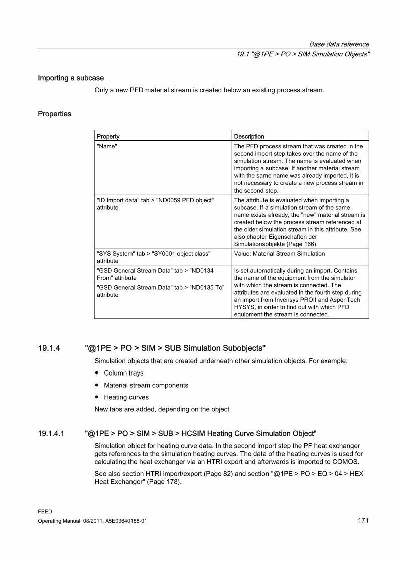
Base data reference 19.1 "@1PE > PO > SIM Simulation Objects"
FEED Operating Manual, 08/2011, A5E03640188-01 171
Importing a subcase Only a new PFD material stream is created below an existing process stream.
Properties Property Description "Name" The PFD process stream that was created in the
second import step takes over the name of the simulation stream. The name is evaluated when importing a subcase. If another material stream with the same name was already imported, it is not necessary to create a new process stream in the second step.
"ID Import data" tab > "ND0059 PFD object" attribute
The attribute is evaluated when importing a subcase. If a simulation stream of the same name exists already, the "new" material stream is created below the process stream referenced at the older simulation stream in this attribute. See also chapter Eigenschaften der Simulationsobjekte (Page 166).
"SYS System" tab > "SY0001 object class" attribute
Value: Material Stream Simulation
"GSD General Stream Data" tab > "ND0134 From" attribute "GSD General Stream Data" tab > "ND0135 To" attribute
Is set automatically during an import. Contains the name of the equipment from the simulator with which the stream is connected. The attributes are evaluated in the fourth step during an import from Invensys PROII and AspenTech HYSYS, in order to find out with which PFD equipment the stream is connected.
19.1.4 "@1PE > PO > SIM > SUB Simulation Subobjects" Simulation objects that are created underneath other simulation objects. For example:
● Column trays
● Material stream components
● Heating curves
New tabs are added, depending on the object.
19.1.4.1 "@1PE > PO > SIM > SUB > HCSIM Heating Curve Simulation Object" Simulation object for heating curve data. In the second import step the PF heat exchanger gets references to the simulation heating curves. The data of the heating curves is used for calculating the heat exchanger via an HTRI export and afterwards is imported to COMOS.
See also section HTRI import/export (Page 82) and section "@1PE > PO > EQ > 04 > HEX Heat Exchanger" (Page 178).
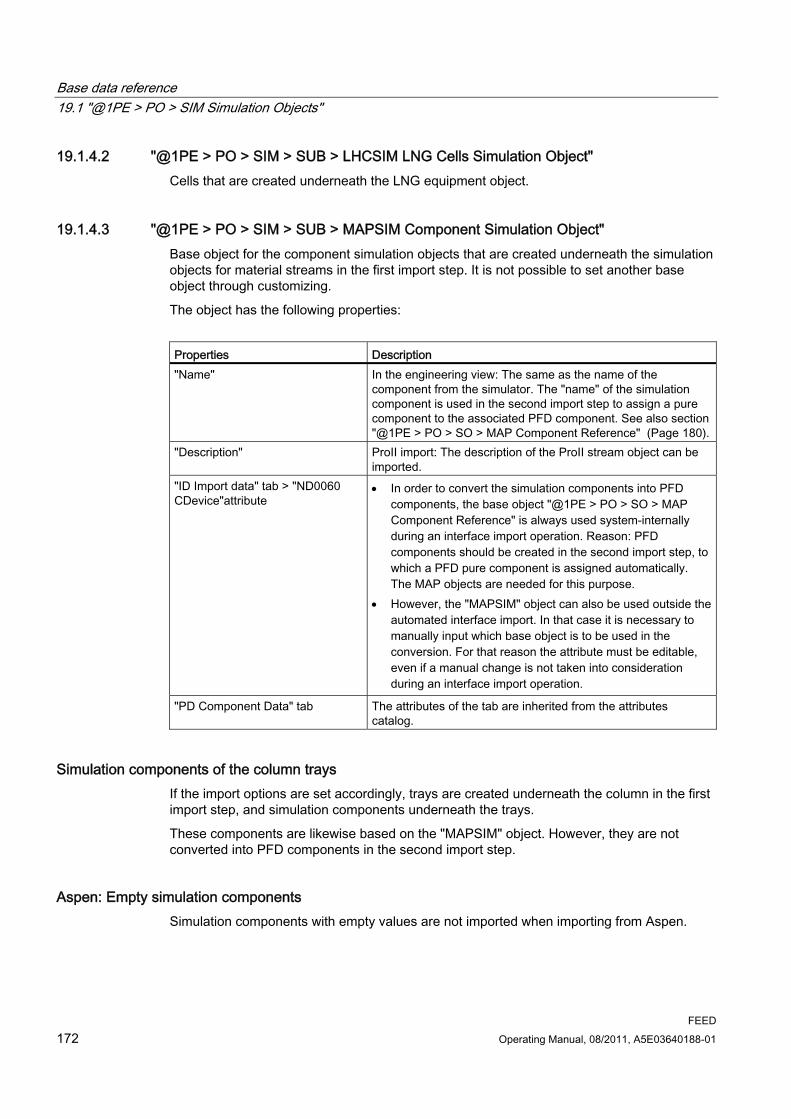
Base data reference 19.1 "@1PE > PO > SIM Simulation Objects"
FEED 172 Operating Manual, 08/2011, A5E03640188-01
19.1.4.2 "@1PE > PO > SIM > SUB > LHCSIM LNG Cells Simulation Object" Cells that are created underneath the LNG equipment object.
19.1.4.3 "@1PE > PO > SIM > SUB > MAPSIM Component Simulation Object" Base object for the component simulation objects that are created underneath the simulation objects for material streams in the first import step. It is not possible to set another base object through customizing.
The object has the following properties:
Properties Description "Name" In the engineering view: The same as the name of the
component from the simulator. The "name" of the simulation component is used in the second import step to assign a pure component to the associated PFD component. See also section "@1PE > PO > SO > MAP Component Reference" (Page 180).
"Description" ProII import: The description of the ProII stream object can be imported.
"ID Import data" tab > "ND0060 CDevice"attribute
In order to convert the simulation components into PFD components, the base object "@1PE > PO > SO > MAP Component Reference" is always used system-internally during an interface import operation. Reason: PFD components should be created in the second import step, to which a PFD pure component is assigned automatically. The MAP objects are needed for this purpose.
However, the "MAPSIM" object can also be used outside the automated interface import. In that case it is necessary to manually input which base object is to be used in the conversion. For that reason the attribute must be editable, even if a manual change is not taken into consideration during an interface import operation.
"PD Component Data" tab The attributes of the tab are inherited from the attributes catalog.
Simulation components of the column trays If the import options are set accordingly, trays are created underneath the column in the first import step, and simulation components underneath the trays.
These components are likewise based on the "MAPSIM" object. However, they are not converted into PFD components in the second import step.
Aspen: Empty simulation components Simulation components with empty values are not imported when importing from Aspen.

Base data reference 19.1 "@1PE > PO > SIM Simulation Objects"
FEED Operating Manual, 08/2011, A5E03640188-01 173
19.1.4.4 "@1PE > PO > SIM > SUB > TRSIM Column Tray Simulation Object" Column trays are only imported if the import objects have been configured accordingly.
The simulation trays are created automatically with the following name: "Tray<counter>".
Properties Tab Description "GSD General Stream Data" "LPH1 Bulk liquid phase" "LPH2 Light liquid phase" "LPH3 Heavy liquid phase" "VPH Gas phase" "TR Tray"
These tabs are filled during the import operation. The values of these tabs can also be taken over by the Equipment Case of the PF tray after the second import step. For this, the Equipment Case gets a reference to this simulation tray. See also Section "@1PE > PO > EC > 08 > CCS > TRAEC Tray Layout (General)" (Page 180).
"SYS System" The "Simulation tray" value is in the "Object class" attribute.
19.1.5 "@1PE > PO > SIM > XXSI Simulation Import Objects" The import objects for the Aspen Plus import operation are located underneath this node.
In contrast to the other objects that are managed underneath the "SIM" node, these two objects are created before the first import step is carried out and are not converted into PFD objects.
19.1.5.1 "@1PE > PO > SIM > XXSI > AXSI Aspen XML-Simulation Import" This base object is for the import object of level 1.
Function The base object defines the user interface through which the import runs and provides the import functionality.
Create the object in the "SIMD" folder in the planning view. To do this, select the "New > AXSI Aspen XML-Simulation Import" command in the context menu.
"Import data" tab This tab controls the individual import steps. Its attributes derive from the attributes catalog.
Exception: The "Start Import", "Create PFD Objects", and "Place PFD Streams" buttons are created at the AXSI import object.
Following attributes must be configured in the base data:

Base data reference 19.1 "@1PE > PO > SIM Simulation Objects"
FEED 174 Operating Manual, 08/2011, A5E03640188-01
Attribute Name Description "Design Case" field "ND0140" Enter the main case here. "DESIGN" is specified
as the main case in the COMOSDB. Enter another value here if necessary. The field must not remain blank. If the attribute is blank in the planning view, no PFD objects can be created.
"Start Import" button "BUTTON1" "Start partial import" button "BUTTON5" "Place PFD Streams" button "BUTTON3" "Create PFD Objects" button "BUTTON2"
These buttons have an OnClick() script in the COMOSDB that initiates the relevant import step of the standard import operation. Do not delete this script. If necessary, you can expand the OnClick() script to include your own calls. See also chapter Import objects: Buttons (Page 125).
The following attributes are set by the user in the planning view:
Attribute Name Description "Import file" field "ND0123" The AspenTech Aspen Plus XML file must be
selected here. A link to the source file is always created. The file should have a defined structure. See also chapter Options for XML nodes in the AspenTech Aspen Plus simulator (Page 37).
"Import in Process Unit" field "ND0116" An entry is required here if the PFD objects in step 2 are to be created below a process unit other than that of the direct owner structure.
The following attributes are filled in the planning view with data from the simulation run during the first import step:
● "ND0118 Description Simulation Run"
● "ND0119 Date Simulation Run"
● "ND0120 User Information"
● "ND0121 User ID"
● "ND0294 Aspen version"
● "ND0122 Log text": Entries regarding possible errors or incorrect configurations are output here during the import operation.
The attribute can only store a limited number of characters. Because of that, an additional TXT or XML file is created in the "Temp" user directory, containing all log messages, i.e. also the ones that could not be stored in the log attribute. The full log information is an important tool for the administrator when configuring the import.
"IP Import options" tab The tab is inherited from the tabs catalog: "@1PE > DS > CC > CUT > CIE > ASPEN > IP Import options"
The attributes of the tab are preconfigured in the COMOSDB with the values given below, but they can also be set in the engineering view.
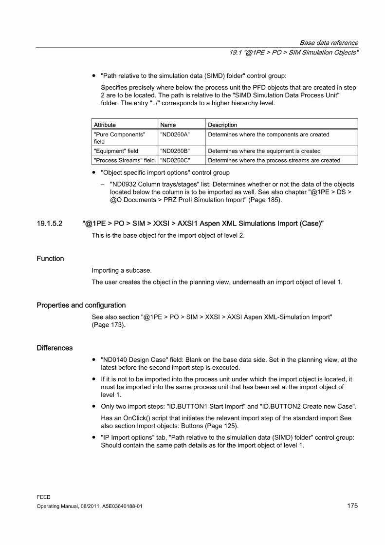
Base data reference 19.1 "@1PE > PO > SIM Simulation Objects"
FEED Operating Manual, 08/2011, A5E03640188-01 175
● "Path relative to the simulation data (SIMD) folder" control group:
Specifies precisely where below the process unit the PFD objects that are created in step 2 are to be located. The path is relative to the "SIMD Simulation Data Process Unit" folder. The entry "../" corresponds to a higher hierarchy level.
Attribute Name Description "Pure Components" field
"ND0260A" Determines where the components are created
"Equipment" field "ND0260B" Determines where the equipment is created "Process Streams" field "ND0260C" Determines where the process streams are created
● "Object specific import options" control group
– "ND0932 Column trays/stages" list: Determines whether or not the data of the objects located below the column is to be imported as well. See also chapter "@1PE > DS > @O Documents > PRZ ProII Simulation Import" (Page 185).
19.1.5.2 "@1PE > PO > SIM > XXSI > AXSI1 Aspen XML Simulations Import (Case)" This is the base object for the import object of level 2.
Function Importing a subcase.
The user creates the object in the planning view, underneath an import object of level 1.
Properties and configuration See also section "@1PE > PO > SIM > XXSI > AXSI Aspen XML-Simulation Import" (Page 173).
Differences ● "ND0140 Design Case" field: Blank on the base data side. Set in the planning view, at the
latest before the second import step is executed.
● If it is not to be imported into the process unit under which the import object is located, it must be imported into the same process unit that has been set at the import object of level 1.
● Only two import steps: "ID.BUTTON1 Start Import" and "ID.BUTTON2 Create new Case".
Has an OnClick() script that initiates the relevant import step of the standard import See also section Import objects: Buttons (Page 125).
● "IP Import options" tab, "Path relative to the simulation data (SIMD) folder" control group: Should contain the same path details as for the import object of level 1.

Base data reference 19.2 PFD objects
FEED 176 Operating Manual, 08/2011, A5E03640188-01
19.1.5.3 "@1PE > PO > SIM > XXSI > SIMCASE Simulation Case" Only of importance if the alternative planning structure is used.
See also Section Structure for import below process unit or process (Page 33).
19.2 PFD objects
Distinctions within the term "PFD objects" Only objects for equipment and process streams are placed on a PFD diagram. Equipment and process streams are PFD objects in the narrower sense.
The other base objects that are introduced in the following sections are only to be regarded as PFD objects in the broader sense.
They are created in the second import step and fulfill the function of data containers. The data stored in them relate to the equipment or process streams, which is why they are also created underneath these objects. The sole exception are pure components. They are managed separately in the planning view, but likewise have a relation to the PFD objects through their implementation pointers to the components.
19.2.1 "@1PE > PO > EQ Equipment" The base objects of the PFD equipment are located in this branch. During the import from a simulator, the PFD equipment is created in the second import step.
19.2.1.1 Eigenschaften allgemein
Symbols A symbol for the PFD drawing type must exist on the "Symbols" tab.

Base data reference 19.2 PFD objects
FEED Operating Manual, 08/2011, A5E03640188-01 177
Elements Most of the objects own the following elements on the "Elements" tab:
● PFD Equipment (Equipment simulation objects): Subobjects (components, accessories)
● Equipment Case objects:
– An Equipment Case element for the main case and the subcases:
Must exist for the simulation import.
– If default cases are required:
One Equipment Case element for each of the default cases "DESIGN", "MAX", and "MIN"
– Base objects: From the corresponding subnode of "@1PE > PO > EC Equipment cases"
● Equipment Rating object:
Object that stores the case-specific dimensions of the equipment. Must be created manually.
Base object. From the corresponding subnode of "@1PE > PO > ER Equipment Rating Cases"
Linked attributes "TD Technical data" tab > "ND0301 Active equipment case" attribute:
● Here you determine the active case. All Equipment Case objects that are located below the equipment are offered.
The attributes of the "TD Technical data" and "PD > Process Data" tabs are linked with the equipment case selected here, and their values are taken from the active equipment case.
● The OnChange() and FillCombolist() scripts prepared in the COMOSDB at the attribute must not be deleted.
● In the simulation import, the attributes of the Equipment Case are linked in turn with those of the simulation object.
"SYS System" tab This is, for example, where the attributes for the object class and for changing the unit system are located.
The tabs are inherited from the tabs catalog.
19.2.1.2 "@1PE > PO > EQ > 02 > COL Column" This is the base object for a PFD column.

Base data reference 19.2 PFD objects
FEED 178 Operating Manual, 08/2011, A5E03640188-01
"Elements" tab "EQ > 08 > COS Column Section":
A structure, underneath which the various column sections are prepared. The section is created manually.
If the column is created via an assembly, then a section is created automatically underneath the column, and a tray is created underneath that section.
See also "@1PE > PO > EQ > 08 > COS Column Section" (Page 179)
"@1PE > PO > EQ > 08 > CCS > TRA Tray Layout (General)" (Page 179)
19.2.1.3 "@1PE > PO > EQ > 04 > HEX Heat Exchanger"
"PD Process Data 1" tab Attribute Name Description "Heating Curve 1" "ND0266c"
"ND0266h" "Heating Curve 2" "ND0266c1"
"ND0266h1" "Heating Curve 3" "ND0266c2"
"ND0266h2"
A maximum of three simulation heating curves (hot and cold).
The references to the simulation objects of the heating curves are set in the second import step. Via an HTRI export, the data of the heating curves is used in order to calculate the heat exchanger. When it is reimported to COMOS, this information is written directly to the heat exchanger PF.
See also HTRI import/export (Page 82)
19.2.1.4 "@1PE > PO > EQ > 04 > LNG Heat Exchanger" This is the base object for a PFD LNG heat exchanger.
Has a cell as an element: "@1PE > PO > EQ > 04 > 08 > CELL LNG Heat Exchanger Cell" base object
Unlilke as, for example, the situation for a column, the cells of the simulation object are also created automatically in the second import step.
The connection information is managed via the cells and not via the LNG heat exchanger.

Base data reference 19.2 PFD objects
FEED Operating Manual, 08/2011, A5E03640188-01 179
19.2.1.5 "@1PE > PO > EQ > 04 > CELL LNG Heat Exchanger Cell"
Base object for the cell of an LNG heat exchanger In contrast to, for example, column trays, PFD cells are created automatically for the cells of the simulation object in the second import step.
The connection information is managed via the cells and not via the LNG heat exchanger.
19.2.1.6 "@1PE > PO > EQ > 08 > CCS > TRA Tray Layout (General)"
Base objects for a tray When a column is created via one of the assemblies prepared in the COMOSDB, a column section is created automatically underneath the column, and a tray is created underneath that section. Additional trays are created using the "New" command in the shortcut menu.
From its active Equipment Case the PF tray takes over the values of the following tabs:
● "VPH Gas"
● "LPH Liquid"
● "PD Process Data"
● "TS Technical data"
19.2.1.7 "@1PE > PO > EQ > 08 > COS Column Section" A structure, underneath which the various column sections are prepared.
Simulation import If the simulation column has a reference to one of the assemblies prepared in the COMOSDB, the section is automatically created together with the column via the assembly, and a tray is created underneath the section.
19.2.2 "@1PE > PO > EC Equipment Cases" Containers that store the case-specific data of the PF equipment.
The branch has the same structure as "@1PE > PO > EQ".
A number of attribute values are passed from the active Equipment Case to its PF equipment.
See also Eigenschaften allgemein (Page 176)
Base data reference 19.2 PFD objects
FEED 180 Operating Manual, 08/2011, A5E03640188-01
19.2.2.1 Eigenschaften allgemein
"TD Mechanical Data" tab "ND0054 Equipment from simulation" attribute
A reference to the associated simulation object is automatically set when creating the Equipment Case during the second step of the simulation import.
The properties of the simulation object are passed to the Equipment Case via a mapping table ("Mechanical Data" and "Process Data" tabs).
"SYS System" tab The same function as with the equipment.
Elements:
● Mapping table: "Virtual" control group: "Off"
● Rating Cases: "Virtual" control group: "N times"
19.2.2.2 "@1PE > PO > EC > 02 > COLEC Column" This is the base object for the Equipment Cases of the column.
19.2.2.3 "@1PE > PO > EC > 08 > CCS > TRAEC Tray Layout (General)"
Base object for the Equipment Cases of trays "TD Mechanical data" tab > "ND0054 Equipment from simulation" attribute:
During a simulation import the reference to the underlying simulation tray must be set manually.
The Equipment Case takes over the values from the simulation tray of the following tabs:
● "VPH Gas"
● "LPH Liquid"
● "PD Process Data"
● "TD Mechanical Data"
19.2.3 "@1PE > PO > SO > MAP Component Reference"
Base object for PF components The PF components are created in the second import step as counterparts for the simulation components. It is not possible to use a different base object for the PF components in the interface import.

Base data reference 19.2 PFD objects
FEED Operating Manual, 08/2011, A5E03640188-01 181
The PF components are created underneath the PF material streams. Two references are set when they are created for the purposes of better data management:
● To their simulation component, from which the values of the "PD Component Data" tab are inherited
● To their pure component, from which the values of the "SD Pure component data" tab are inherited
COMOS proceeds as follows to assign a pure component to the PF component:
COMOS takes the name of the referenced simulation component and checks whether there is already a pure component in the "AMA Pure components" folder for which the following applies:
One of the names entered in the "ND0013 Name from simulation" attribute is identical to the name of the simulation component.
If no matching pure component is found, the component is not created.
Properties Property Description "Name" Automatically generated via the text mask at the base object "Description" The same as the description of the assigned pure component "Implementation" The pure component assigned during creation is set automatically
"PD Component Data" tab ● "ND0139 Material from simulation": Link to the underlying simulation component. The
reference is entered automatically.
● The remaining attributes of the tab are linked with the simulation component that is referenced in the "PD.ND0139 Material from simulation" component; the values are taken over automatically from there.
See also section "@1PE > PO > SO > PS Process Stream" (Page 183).
"SD Pure component data" tab ● "ND0048 Component": Link to the assigned PF pure component. The reference is
entered automatically.
● The other attributes of the tab are linked with the pure component that is referenced in "ND0048 Component"; its values are taken over automatically from there.
Configuration of the attributes:
"SYS System" tab This is where the attributes for the object class and for changing the unit system are located. The tabs are inherited from the tabs catalog.

Base data reference 19.2 PFD objects
FEED 182 Operating Manual, 08/2011, A5E03640188-01
19.2.4 "@1PE > PO > SO > MAS Pure Components" The pure components library is located in this node.
"@1PE > PO > SO > MAS > MA0000 Pure Component" In the planning view, this pure component is used in both the first and the second import step.
The base object "MA0000" is always used in the first import step when importing a file from a simulator, to create the simulation pure components.
The base object "MA0000" is also used in the second import step if COMOS cannot find a matching pure component in the pure components library for a simulation pure component.
"@1PE > PO > SO > MAS > MA[number]" In the planning view these pure components are used in the second import step, when a simulation pure component is to be converted into a PF pure component for the first time. COMOS reads the name of the simulation pure component and checks whether there is a pure component underneath "@1PE > PO > SO > MAS" for which the following applies:
One of the names entered in "ND0013 Name from simulation" is identical to the name of the simulation pure component. If such a pure component is found, it is created in the planning view in the "AMA" folder underneath the process.
If no such pure component is found, COMOS uses the "MA0000" object.
19.2.5 "@1PE > PO > SO > MS Case" This is the PF counterpart to the simulation material stream.
It stores the case-specific data for its process stream and is created automatically during the second import step:
● Import of the main case:
The material stream for the main case is created together with its process stream and the default cases.
● Importing a subcase:
Only the PF material stream for the imported subcase is created, underneath an existing process stream.
Properties Property Description "Name" Gets the name of the case that had been input at the import object "Class" Position "Subclass" Material stream

Base data reference 19.2 PFD objects
FEED Operating Manual, 08/2011, A5E03640188-01 183
"GSD General Stream Data" tab "ND0015 Stream from simulation" attribute, set automatically during the second import step.
"SYS System" tab This is where the attributes for the object class and for changing the unit system are located.
See also "@1PE > PO > SO > PS Process Stream" (Page 183)
19.2.6 "@1PE > PO > SO > PS Process Stream"
Base object for PFD process streams These are created automatically in the second import step:
● Import of the main case:
A process stream is created for each simulation material stream below the import object. The process stream gets the "Name" of the simulation material stream.
Pro/II: If the Pro/II description was imported for the simulation material stream, the process stream also takes over the "Description", else it takes over the "Description" from its base object.
The PFD material stream for the main case and additional material streams for the default cases are created below the process stream.
● Importing a subcase:
A new process stream is only created if a simulation material stream with this name is imported for the first time.
"System" tab Property Description "Name" The same name as the the simulation material stream "Class" Position "Subclass" Pipe

Base data reference 19.2 PFD objects
FEED 184 Operating Manual, 08/2011, A5E03640188-01
"Elements" tab The following elements must be created:
● An element for a material stream with the following properties:
– Option "Virtual" equals "N times".
– Base object reference to "@1PE > PO > SO > MS Case"
This element is required to create the main case and the subcases.
● If default cases are required: At least one element for a default material stream.
In the COMOSDB, there are three default cases: "DESIGN", "MIN", and "MAX".
Properties:
– "Virtual" option: Off
The material streams are created automatically together with the process stream.
– Base object reference to "@1PE > PO > SO > MS Case"
● An element for segmentation of the process stream must exist:
– "Name" SEG
– "Class": Element
"Subclass": Pipe
– Option "Virtual" equals "N times"
"Connectors" tab Two connectors of type "P&ID" must be prepared here:
● Input: "I1"
● Output: "O1".
"ASD Actual Stream Data" tab Contains the case-specific data of the process stream. The values taken over from the process streams by means of attribute linking:
"Material stream list" tab If a base object has the "Position" class and the "Pipe" subclass, the "Material stream list" tab is automatically made available on the "Configuration" tab of the base object.
The base object for process streams is configured in the COMOSDB in such a way that the tab is displayed in the engineering view.
The tab is based on an query and reads important data from all material streams that are located below the process stream.
The material stream of the active case is shown bolded in the list.

Base data reference 19.3 "@1PE > DS Data Structures"
FEED Operating Manual, 08/2011, A5E03640188-01 185
"RI Presentation" tab This tab controls the graphic display of the process stream on the plan. Most attributes are saved with standard tables.
Tabs "RP Routing Parameters" and "TS Technical data" The tabs are important when carrying out cost estimations. They are inherited from the catalog.
19.3 "@1PE > DS Data Structures"
19.3.1 "@1PE > DS > @O Documents"
19.3.1.1 "@1PE > DS > @O Documents > PRZ ProII Simulation Import"
Document class Base object for the import object of levels 1 and 2 of the Invensys PRO/II interface. This base object defines the user interface through which the import operation is controlled and provides the import functionality.
The document with which the import operation is executed in the planning view must be of document type "ProII". Then it automatically has a link to this base object and thus to the required import functionality.
The document must be created below the SIM Simulation Data Process Unit" folder, either by using the "New" context menu or by using drag&drop.
Requirement A base object whose name is the same as the file extension of the Invensys PRO/II simulator and which has a base object reference to "@1PE > DS > @O > PRZ" is prepared in the COMOSDB under the "@System > @D > @DocumentTypeMapping" node.
Effect The document is created automatically. The reference to the source file is set automatically. The user decides whether a copy or a link should be created.
The import file is referenced automatically on the "PRO/II" tab.
"ID Import data" tab This tab controls the individual import steps.

Base data reference 19.3 "@1PE > DS Data Structures"
FEED 186 Operating Manual, 08/2011, A5E03640188-01
It functions in the same way as the tab of the Aspen Plus import object. See also chapter "@1PE > PO > SIM > XXSI > AXSI Aspen XML-Simulation Import" (Page 173).
The tab differs in the following ways from the Aspen Plus import object:
● "ProII" tab: There is no attribute referenced for the import file.
● "BUTTON3 Place PFD Equipment"
Not available in the Aspen Plus import.
● "BUTTON4 Place PFD Streams"
Analogous to the Aspen Plus import object, but with its own OnClick() script.
● "ND0140 Design Case":
Unlike with the Aspen Plus import, in a Invensys PRO/II import, there is no separate base object for the import of subcases. Instead, the Invensys PRO/II import objects are nested within each other.
– Import object of level 1 (main case):
Enter the main case.
The main case and default cases are created.
– Import object of level 2 (subcase):
A subcase is created.
– "DESIGN" is preconfigured as the main case in the COMOSDB.
– This attribute should not be left blank, since otherwise the PFD objects cannot be created.
● No attribute for the number of the used Invensys PRO/II version.
In contrast to the Aspen Plus import object, the PRO/II import object has the following attribute:
● "ND0249 Import into Document":
If the PFD objects are to be placed on another PFD in steps 3 and 4 than on the PFD that had automatically been created below the process unit.
Can be set by the user in the planning view (optional).
"IP Import options" tab The tab is inherited from the tabs catalog.
The attributes of the tab are preconfigured in the COMOSDB with the values given below, but they can also be set in the engineering view.
Base data reference 19.3 "@1PE > DS Data Structures"
FEED Operating Manual, 08/2011, A5E03640188-01 187
● "Path relative to the simulation data import (SIMD)" control group:
Specifies below which objects the PFD objects that were created in step 2 are to be located.
See also chapter "@1PE > PO > SIM > XXSI > AXSI Aspen XML-Simulation Import" (Page 173).
● "Object specific import options" control group:
– "ND0932 Column trays/stages":
Specifies whether or not the data of the objects located below the column is to be imported as well.
"Not imported": Only the data of the column itself are imported; the data of the associated trays and components are not imported.
"trays/stages without composition": The data of the column and trays is imported. The data of the components is not imported.
"trays/stages & compositions": The data of the column, trays, and components is imported.
– "ND0931 Stream/tray/stage compositions":
Specifies which attributes on the "PD Component Data" tab are to be imported for the simulation components.
Does not exist: COMOS calculates the values.
"SYS System" tab "SY0001 Object Class" attribute: Stored using standard table
This attribute is not evaluated during the import operation. It can be used by the user in scripts for internal purposes, for example when making a search for all objects of a particular class.
19.3.1.2 "@1PE > DS > @O Documents > HYSYS HYSYS Simulation Import"
"Document" class Base object for the import object of levels 1 and 2 of the AspenTech HYSYS interface. This base object defines the user interface through which the import operation is controlled and provides the import functionality.
The document of type "HSC" must be created below the "SIMD" folder.
Requirement A base object whose name is the same as the file extension of the AspenTech HYSYS simulator is prepared in the COMOSDB under the "@System > @D > @DocumentTypeMapping" node.

Base data reference 19.4 Auswahllisten
FEED 188 Operating Manual, 08/2011, A5E03640188-01
Effect The document is created automatically. The reference to the source file is set automatically.
"ID Import data" tab This tab controls the individual import steps. It functions in the same way as the tab of the Invensys PRO/II import object. See also chapter "@1PE > DS > @O Documents > PRZ ProII Simulation Import" (Page 185).
"IP Import options" tab The tab is inherited from the tabs catalog. It functions in the same way as the tab of the Invensys PRO/II import object, but it has fewer attributes.
See also chapter "@1PE > DS > @O Documents > PRZ ProII Simulation Import" (Page 185).
19.3.2 "@1PE > DS > @Y Attributes Catalog"
Attributes catalog for process technology Most of the attributes of the simulation and PFD objects originate from this node.
19.3.3 "@1PE > DS > CC Tabs Catalog" Tabs are prepared here which are then used and extended in objects involved with the import.
19.4 Auswahllisten
"@1PE Process Engineering" branch The standard tables that are relevant for the import are located in this branch. The tables that were prepared in the COMOSDB should not be deleted but can be extended if desired.
The following standard tables are of special importance for simulation import operations:
"@1PE > AE Aspen Units" Assigns Aspen Plus measurement units to COMOS measurement units. See also section Mapping of units between AspenTech Aspen Plus or Bryan Research & Engineering ProMax and COMOS (Page 123).

Base data reference 19.5 Creating and grouping pure components under the "AMA" folder
FEED Operating Manual, 08/2011, A5E03640188-01 189
"@1PE > AE > DELTA-T Aspen units for domain DELTA-T" An Aspen Plus unit can be part of multiple unit groups. Here the Aspen Plus units that belong to the DELTA-T unit group.
"@1PE > AE > HEAD aspen units for HEAD domain" This is where the Aspen Plus unit belonging to the HEAD physical unit group is located.
19.5 Creating and grouping pure components under the "AMA" folder You can make settings defining how new pure components are created and grouped under the "AMA" folder on the "Units" tab in the Navigator.
Corresponding menu commands are available to the user in the shortcut menu of the "AMA" folder and in the shortcut menu of a component group located at a lower level, e.g. "Solids", "Liquids", or "Gases".
Example 1. Call the example project to illustrate this.
2. Select the "Solids" component group.
3. Navigate to the base object via the shortcut menu and view the pure components in the component group.
4. Use the existing structure as a guide and then make your entries in the engineering project.
See also Creating components (Page 23)
19.6 Object classes used The following object classes are used in the FEED module for CDevice and Device system types:
Classes ● Revision
● Action

Base data reference 19.6 Object classes used
FEED 190 Operating Manual, 08/2011, A5E03640188-01
Subclasses ● Query
● Material stream
● Material pointer
You can find more information on this topic in the "Basic Operation" manual, keyword "Object classes for system types CDevice/Device".

FEED Operating Manual, 08/2011, A5E03640188-01 191
User interface reference 2020.1 "Import options" tab
Control group Option Function "Path relative to the simulation data (SIMD) folder" "Pure components",
"Equipment", "Process streams" fields:
Only administrators are permitted to set this import option.
"Object specific import options" control group "Column trays/stages"
standard table: For Invensys Pro/II only "Not imported" value:
Only the data of the column is imported. The data of the associated trays and components is not imported.
"Trays/stages & compositions" value:
The data of the column, trays, and components is imported. (Default setting)
"Components stream/tray/stage" standard table
Not for Evonik EbsilonProfessional Defines which attributes are imported when importing components to the "Component data" tab. Possible values: "Only bulk mole fractions" "Mole fractions of all phases" "Bulk fractions and flows"
Others "Calculate stream
properties" option For Invensys Pro/II only Activated (default setting): The simulator is triggered once again and the stream properties are recalculated. Any stream properties that are missing in the source file are calculated and are also imported.
"Calculate linked specifications for composition items" option
Activated: Linked attributes are recalculated at the components. This slows down the import process.
"Map by name" option For Evonik EbsilonProfessional only Activated: If a PFD object with the same name as the simulation object already exists, the simulation object gets a link to this PFD object.

User interface reference 20.2 "Partial import" window
FEED 192 Operating Manual, 08/2011, A5E03640188-01
Control group Option Function "Create dummy objects"
option Activated: Wildcard objects are used for the import.
"Check unique names" option
Activated: Only objects with a unique name are imported.
20.2 "Partial import" window
"Display" control group Option Description "Streams" Displays only objects whose simulation object is a stream. "Equipment" Displays only objects whose simulation object is equipment. "Show only importable objects"
Displays only objects to which a simulation object is assigned.
"Group objects" option Activated: Groups the objects that are assigned to the same simulation object.
"Selection" control group Option Description "All" Activates the option for all objects in the "Import" column of the import
table. "None" Deactivates the option for all objects in the "Import" column of the
import table. "Streams" Displays only objects whose simulation object is a stream. "Equipment" Displays only objects whose simulation object is equipment. "User-defined" Allows the user to customize the selection of objects in the import table.
Import table The import table shows the objects of the simulation file corresponding to the options you have selected in this window.
If the option of an object is activated in the "Import" column, this object will be imported when you click on the "OK" button.
Status display A status display is located below the import table. This indicates how many importable objects are available and how many of them you have selected.

FEED Operating Manual, 08/2011, A5E03640188-01 193
Glossary
Boundary stream A boundary stream represents the flow of material components between process units without already defining concrete pipes. In COMOS, the boundary stream is encapsulated in a "Boundary stream" object.
A boundary stream is created automatically when you use the "Connection" tool to interconnect process units on a block diagram.
Case (equipment case) See equipment case.
Case (general) A case (Run Case) defines typical conditions under which a plant is operated. In COMOS, case-specific data is encapsulated in self-contained objects:
● For process streams in material streams
● For equipments in equipment cases
The standard cases in COMOS are Design, Max, and Min. You have the option of creating and importing any additional cases using the Run Case Manager.
Case (SIMCASE) See simulation case object.
Case Manager The Case Manager is a user interface in which you manage case-specific objects in your process.
You have the option of carrying out the following actions with new objects (= cases):
● Create
● Delete
● Rename
● Copy
● Complete
You carry out these actions for either the entire process or a process unit.

Glossary
FEED 194 Operating Manual, 08/2011, A5E03640188-01
Component The chemical materials that are used in a process are encapsulated in "Component" objects in COMOS. The components of a process are collected under the process in the "AMA Components" folder.
Material input arrows/material output arrows and components have references to components.
During a simulation import, the components being used are automatically created in COMOS. You also have the option of creating components manually.
In COMOS, case-specific material data for a process stream is managed in components. The components are located directly underneath the material stream of the corresponding case.
Each component has a reference to the component on which it is based.
You create the components manually.
Design case A design case (Design Case) defines typical conditions for a plant at the engineering stage. Otherwise, the information in the definition of case (Run Case) applies.
See Case (general).
Equipment All large devices such as containers, pumps, or columns. The equipment is arranged in the Navigator according to process units.
You can either import the equipment to COMOS by running a simulation import so that it is placed on a PF automatically or you can create the equipment manually.
Case-specific data for a piece of equipment is managed in case objects that are located directly underneath the equipment in the Navigator.

Glossary
FEED Operating Manual, 08/2011, A5E03640188-01 195
Equipment case In COMOS, an equipment case is an object that encapsulates all case-specific data for a piece of equipment.
The cases for standard cases are created automatically when the equipment is created. You can create additional cases by running a simulation import or using the Run Case Manager.
Grouping components COMOS offers the option of configuring the contents and layout of mass balances. Component grouping supports the following options:
● Combining components into groups
● Defining the order of the groups and components one after the other
● Excluding individual components from the mass balance
Knowledge base See "Knowledge base".
The knowledge base consists of a set of engineering rules that define when alarms or warning messages are issued for a process.
These rules are defined in queries. When you execute a query, COMOS checks whether the process follows the rules.
Knowledge base See "Knowledge base".
The knowledge base consists of a set of engineering rules that define when alarms or warning messages are issued for a process.
These rules are defined in queries. When you execute a query, COMOS checks whether the process follows the rules.
Material stream In COMOS, case-specific data for process streams is encapsulated in material streams.
Each material stream has a reference to the components that it uses.
The material streams for standard cases are created automatically when the process stream is created. You can create additional material streams by running a simulation import or using the Run Case Manager.
Process In COMOS, the chemical process that you model and manage is encapsulated in a "Process" object. In each case, all objects and documents that are related to the process belong to a single process and, accordingly, are located underneath this process in the Navigator.

Glossary
FEED 196 Operating Manual, 08/2011, A5E03640188-01
Both case management and component grouping can be carried out at process level, if required.
You create the process manually.
Process stream In COMOS, a process stream is an object that represents the flow of material components that takes place between the PF equipment on a PF. A process stream does not define any concrete pipes.
Process streams are created if you carry out the "Place PF objects" step as part of a simulation import, or if you draw on a PF using the "Connection" tool.
Case-specific data of a process stream is managed in material streams that are located directly underneath the process stream in the Navigator.
Process unit In COMOS, a partial step in a process chain is encapsulated in a "Process unit" object.
Both the import of case-specific data and component grouping are normally carried out at process unit level.
The process unit is created automatically when you place the symbol of a process unit on a block diagram.
Simulation case object (SIMCASE) A simulation case object helps you to manage your imports completely separately according to the cases. For each case that you import, you create a SIMCASE. All relevant data for this simulation import is then collected underneath the SIMCASE, from the import document to the simulation objects.
Simulation import document/Simulation import object A simulation import document/import object is a document/object that controls the import process from the simulation software to COMOS. A separate document/object is provided for each of the various simulation programs.
Both the configuration of the import and the actual process are conducted in the simulation import document/import object.
In most cases, the import process is carried out for each process unit.
Simulation object Simulation objects are auxiliary objects for a simulation import. They are created during the first import step, while the second import step involves creating PF objects from the simulation objects.
As a normal user, you only work with PF objects and not with simulation objects.