fÉdÉration internaltonale de ski … · international ski federation internationaler skiverband...
TRANSCRIPT

FÉDÉRATION INTERNALTONALE DE SKI
INTERNATIONAL SKI FEDERATION
INTERNATIONALER SKIVERBAND
Timing Booklet
Cross-Country
Nordic Combined (Cross-Country)
DRAFT
Version 1.0
November 2017
Version 1.0 (DRAFT) November 2017
2
Table of content
1. General 6
1.1. References to race level classifications in Cross-Country 6
1.2. References to race level classifications in Nordic Combined 7
2. Electronic timing 8
2.1. Timing devices 8
2.2. Timing support systems 11
3. Equipment Set-Up (see drawing) 12
3.1. Cable connection 12
3.2. Start and Finish 12
4. Timing 15
4.1. Overview by discipline 15
4.2. Determination of times 15
4.2.1. Level 0 15
4.2.2. Level 1 to 4 16
5. Timing & Data Technical Report 17
5.1. “How-To” Explanation Text Timing & Data Technical Report Form (Software Version) 17
5.2. Timing & Data Technical Report software screen shots 20
6. Criteria for FIS Approved Timing Devices in Cross-Country/Nordic Combined 21
6.1. Timers 21
6.2. Start Gate 23
6.2.1. Setup 23
6.2.2. Technical Specifications for Start Gates 24
6.3. Photocell 26
6.3.1. Installation 26
6.3.2. Photocell types 26
6.3.3. Photocells for the Finish 27
6.3.4. Technical Specifications for the Photocell 28
6.4. Photo finish systems 29
6.4.1. Definition and usage photo finish camera 29
6.4.2. Installation photo finish and video camera system 29
6.4.3. Technical Specifications for the photo finish camera 30
6.5. Start clock 31

Version 1.0 (DRAFT) November 2017
3
6.5.1. Technical Specifications for the start clock (only interval start) 31
6.5.2. Cross Country Individual start 33
6.5.3. Cross Country Handicap start 33
6.5.4. Nordic Combined Gundersen start 33
7. Other timing support systems 34
7.1. Transponder system 34
7.2. Start system 34
7.2.1. Electronic start gun/system 34
7.2.2. Noise detector for start guns 34
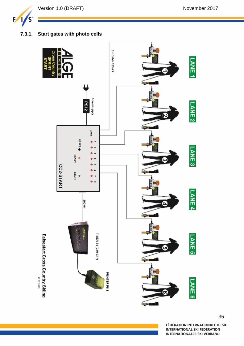
7.3. Heat start gate 34
7.3.1. Start gates with photo cells 35
7.3.2. Start gate with wand 36
7.4. Video control system 37
7.4.1. Start 37
7.4.2. Finish 37
8. Timing without cable connection between start and finish 38
9. Set up drawings 39
9.1. Level 0 – Individual / Sprint Qualification Start 39
9.2. Level 0 – Sprint Final 40
9.3. Level 0 – Mass Starts 41
9.4. Level 0 – Pursuit / Gundersen Start 42
9.5. Level 1-4 – Individual / Sprint Qualification Start 43
9.6. Level 1-4 – Sprint Final 44
9.6.1. Timer A + B, Photo Cells A + B, Photo finish 44
9.6.2. Timer A, Photo Cells A, Photo finish 45
9.6.3. Photo finish A + B 46
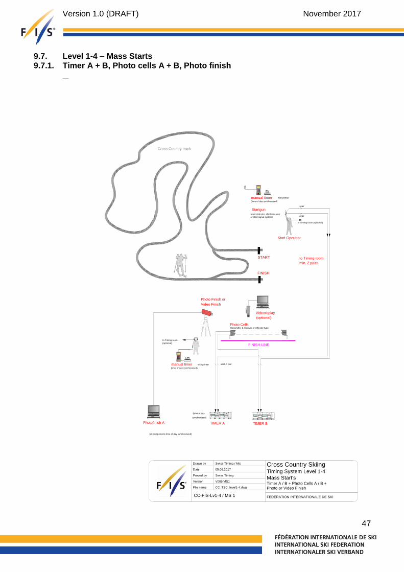
9.7. Level 1-4 – Mass Starts 47
9.7.1. Timer A + B, Photo cells A + B, Photo finish 47
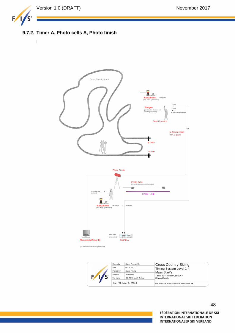
9.7.2. Timer A. Photo cells A, Photo finish 48
9.7.3. Photo finish A + B 49
9.8. Level 1-4 – Pursuit / Gundersen Start 50
9.8.1. Timer A + B, Photo cells A + B, Photo finish 50
9.8.2. Timer A. Photo cells A, Photo finish 51
9.8.3. Photo finish A + B 52
9.9. Level 1-4 – Individual Start (wireless) 53
9.10. Level 1-4 – Mass Start (wireless) 54
10. Important ICR rules for Timing in Cross-Country 55

Version 1.0 (DRAFT) November 2017
4
11. Important ICR rules for Timing in Nordic Combined (Cross-Country) 58
12. Homologation of Timing Equipment 61
13. List of Homologated Timing Equipment 61
14. Conclusion 62
Version 1.0 (DRAFT) November 2017
5
Document Control
Version History Description
Version 1.0 Initial version
Sources drawings
ALGE-TIMING GmbH, Austria Swiss Timing, ST Sportservice GmbH, Germany
Version 1.0 (DRAFT) November 2017
6
1. General
For all competitions listed in the FIS calendar, electronic timekeeping must be used. Electronic timing will always be supplemented by hand timing as a backup system and the results cross -checked between the two systems (ICR 316.1). All timing devices used including start gates, photocells and photo finish systems must be homologated. The most updated list of those devices can be found at the FIS website (see article 13). Races using devices not mentioned on that list will not be considered for FIS points.
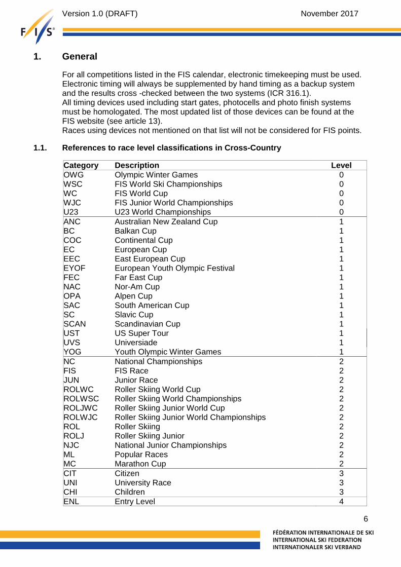
1.1. References to race level classifications in Cross-Country
Category Description Level OWG Olympic Winter Games 0 WSC FIS World Ski Championships 0 WC FIS World Cup 0 WJC FIS Junior World Championships 0 U23 U23 World Championships 0
ANC Australian New Zealand Cup 1 BC Balkan Cup 1 COC Continental Cup 1 EC European Cup 1 EEC East European Cup 1 EYOF European Youth Olympic Festival 1 FEC Far East Cup 1 NAC Nor-Am Cup 1 OPA Alpen Cup 1 SAC South American Cup 1 SC Slavic Cup 1 SCAN Scandinavian Cup 1 UST US Super Tour 1 UVS Universiade 1 YOG Youth Olympic Winter Games 1
NC National Championships 2 FIS FIS Race 2 JUN Junior Race 2 ROLWC Roller Skiing World Cup 2 ROLWSC Roller Skiing World Championships 2 ROLJWC Roller Skiing Junior World Cup 2 ROLWJC Roller Skiing Junior World Championships 2 ROL Roller Skiing 2 ROLJ Roller Skiing Junior 2 NJC National Junior Championships 2 ML Popular Races 2 MC Marathon Cup 2
CIT Citizen 3 UNI University Race 3 CHI Children 3 ENL Entry Level 4
Version 1.0 (DRAFT) November 2017
7
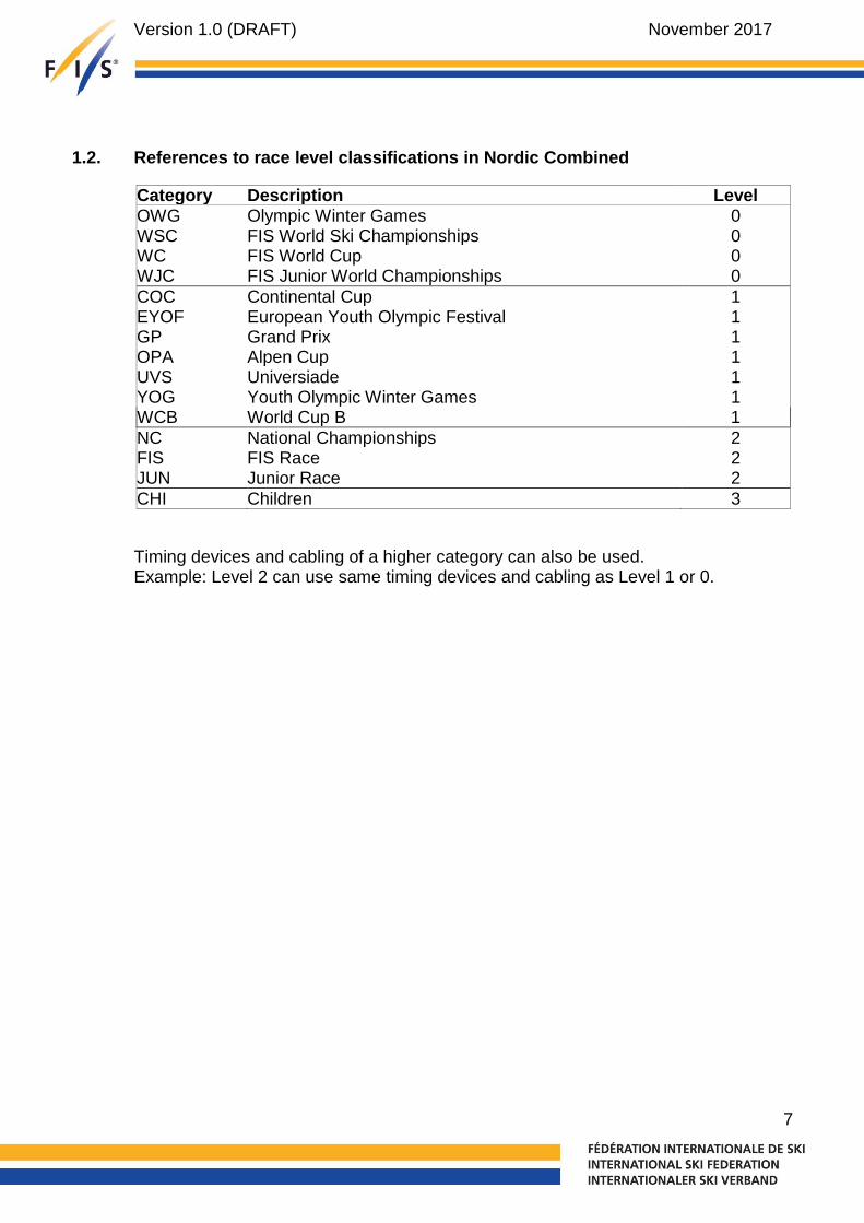
1.2. References to race level classifications in Nordic Combined
Category Description Level OWG Olympic Winter Games 0 WSC FIS World Ski Championships 0 WC FIS World Cup 0 WJC FIS Junior World Championships 0
COC Continental Cup 1 EYOF European Youth Olympic Festival 1 GP Grand Prix 1 OPA Alpen Cup 1 UVS Universiade 1 YOG Youth Olympic Winter Games 1 WCB World Cup B 1
NC National Championships 2 FIS FIS Race 2 JUN Junior Race 2
CHI Children 3
Timing devices and cabling of a higher category can also be used. Example: Level 2 can use same timing devices and cabling as Level 1 or 0.

Version 1.0 (DRAFT) November 2017
8
2. Electronic timing
The following electronic timing technologies can be used to identify the official finish times:
Electronic timing system based on photo cells. The measuring point of the light or photo barrier must be at a height of 25 cm above the snow surface.
Photo finish system. The measuring point will be the toe of the first boot meeting the finish line
2.1. Timing devices
System A Timer System B Timer
Level 0: Start and finish must be connected by cable Level 1-4: Start and finish can be connected by cable or without cable connection. Timing devices without direct cable connection to the main timing system has to be connected to a timing device at the start or finish. Radio connections are not allowed. The use of any electronic device (e.g. optocopler) between start gate and timer or photocell and timer must be specifically compatible and authorized by the manufacturers. All timers always need to be synchronized.
Manual hand timing In all cases for all events at all levels, hand timing is mandatory. Hand timer, with or without printers, showing times to at least 1/100th second should be synchronized to the time of day and used at the start and at the finish. A backup video control system for checking the arrival should be used.
Photo finish camera (line scan camera)
A photo finish system (line scan camera) with synchronized time of day mode used as timing device or tie determination at the finish line.
Transponder are not determined to be used as official time (for system A and B)
Start clock Use of such a start clock is highly recommended for all individual start races at event Levels 1 and 0. A start clock must be used for pursuit and Gundersen starts for each start lane. (CC ICR 315.4.4, NC ICR 515.2.7) Start clock must show time of day and count down.
Synchronization All elements of the timing installation must be installed and be in good working order at least one hour before the beginning of the competition. Timers should be turned on 30 minutes before synchronization to allow the quartz time bases to stabilize. Synchronization must be done no more
Version 1.0 (DRAFT) November 2017
9
than 60 minutes prior to the scheduled start of each race and must not be re-synchronized while the race is in progress. The synchronization impulse for all timers must come from one single device for all timing devices. One minute after synchronization is done, a new impulse must be sent by the start gate or synchronizing contact to check synchronization accuracy on Systems A and B. The maximum allowed difference between system A and B is 0.001 seconds. Should any important discrepancies be observed when this check is performed, synchronization should be redone and checked again prior to the start of the race.
In case you use a start clock, it has to be synchronized together with the system A and B timer.
Manual stopwatch synchronization must be done before or together with the synchronization of the whole system.
Synchronization with GPS
GPS can be used for first synchronization. Synchronization should be done after the GPS device had at least 30 minutes a GPS signal. Timer synchronized with GPS has to be homologated with GPS synchronization. Timers must not be re-synchronized during any race.
Competition in progress
Reminders In case of timing problems, the chief of timing must inform members of the jury or the finish referee immediately. Starter and official timekeeper should agree upon using specific terms and commands during communication. This dialogue should be short and precise, as well as systematically repeated for each competitor. In all cases it is recommended that the starter always informs the timekeeper(s) at the finish before and after a competitor leaves the start. At the end of each race or competition, before sending out the competition results, times from the timing systems and the computer results system must be compared and cross checked for accuracy.

Version 1.0 (DRAFT) November 2017
10
Missed Time A missed time is a time of day that is not shown on the printed tape of the system A timer. If a time from system B is missed but you have it printed on system A it is not considered as a missed time. In case you have a missed time of system A and must replace it by time of day of system B or of a hand time, then you have to recalculate the missed time using ICR rule 316.2.
Notes At the end of the competition, it is send electronically the “Timing &Data Technical Report Form” to the FIS (see section Timing & Data Technical Report Form in this booklet). The printed tapes from the System A, System B and all hand timing records must be handed to the race organization who has to keep it at least 3 months after the competition or after any appeal dealing with timing. A member of the Timing Working Group could check at any time and at any race the timing system connection. A contact of each starting line and finish photocell must be available to connect a FIS timing device. Of course, such connection will be done at least 2 hours before the race start and not during the race.

Version 1.0 (DRAFT) November 2017
11
2.2. Timing support systems
Transponders
Transponders (active systems) can be used as a supporting system to the official
timing system to determine race times and ranking sequences at intermediate timing
points, pre-timing points and finish (unofficial result).
The official result has always to be confirmed by using a FIS homologated timing
system.
Video finish camera
Determination of the finish order at the finish line.
Recommended are video camera systems with minimum 100 frames per second or
higher and HD resolution.

Version 1.0 (DRAFT) November 2017
12
3. Equipment Set-Up (see drawing)
3.1. Cable connection
For events of level 1 to 4 timing without cable connection from the start is permitted for both A and B timing systems (see art. 8 - Timing without cable connection between start and finish). Refer to set-up diagrams that describe in detail how this may be affected. Attention: The cable dedicated to timing functions must be reserved for that purpose only and must be protected from any interference (e.g. speaker systems, snow gun data, etc.). No technical changes during the competition that may alter the transmission of trigger signals (length, capacitance, resistance, etc.) may be effected. The organizer must ensure that cable conduits and other cable runs do not interfere with timing cable functions. It is highly recommended that expert technical testing and verification of these timing cables be performed to assure timing cable integrity.
3.2. Start and Finish
Start gate (individual)
Minimum of 2 electronically isolated contacts activated by 1 wand. Timing wires 1 & 2 must be connected to separate start gate contacts using separate connectors. The wand must be installed so that starting is impossible without it opening.
Heat start gate (heat starts)
Electronic or mechanical start gate by start lane with optical indication of a false start either on the gate or control interface. Mandatory for use at event Level 0.
Start clock Must show time of day, countdown status and can have acoustic signal (5 seconds countdown). Must be synchronized with the other timing systems. Use of such a start clock is highly recommended for all individual start and must be used for pursuit and Gundersen competitions and is mandatory for use at event Level 0. Indicates the start gap 3 sec. before and after the start signal with green and red lights (Level 0)
For handicap starts a start clock must be used for each start lane showing time of day. Count down sound is not mandatory.
Voice communication
Timing impulse and voice communication functions can be separated on different wire pairs. If radios are used for voice communication, a dedicated channel must be used. For interval starts voice communication over cable is recommended.

Version 1.0 (DRAFT) November 2017
13
Timing cables Make sure that cables cannot be torn out at the start by a competitor, or by any other person next to the starting area. Optical Cables: If a converter is necessary between timing cables and optical cables, then the converter must be approved by the FIS.
Photo cells at the finish line
Please refer to the attached section that explains photocell use. Wire must be used to connect photocells to the timer. Wireless is not allowed.
Photo finish camera Installation on a stable tripod or fixed construction in alignment to the photo cell detection line. The organizer should provide a stable platform for tripod installation. The photo finish system should be used in time of day mode. The photo finish system power should be secured by an UPS for a minimum of 20 minutes. The photo finish system must work at ambient temperatures from -10° to +60°C.
Video camera Installation on a stable tripod or fixed construction in alignment to the photo cell detection line. The video system power should be secured by an UPS for a minimum of 20 minutes. The photo finish system must work at ambient temperatures from -10° to +60°C.
Start gun noise detector / electronic start gun / start signal system
System which either detects an acoustic start signal or trigger an electronic noise as start signal and gives an electronic start impulse to the timing system. The start system must be installed in a way that every competitor at the start can hear the acoustic start signal loud and clear.
The start system must work at ambient temperatures from -20° to +60°C.

Version 1.0 (DRAFT) November 2017
14
Photo cells installation

Version 1.0 (DRAFT) November 2017
15
4. Timing
4.1. Overview by discipline
Individual Sprint Qualification
Sprint Finals
Mass Start
Pursuit / NK Gundersen Start
Team Sprint
Result time precision
1/10s 1/100s 1/100s 1/10s 1/10s 1/100s
Time recording precision (ToD)
1/10000s or higher
Start system A+B
Start gate Start signal based start system
Start clock Start signal based start system
Backup start Hand time Hand time
Finish System A+B
Photo cell Photo finish
Photo finish Photo cell + Video finish
Backup finish Photo finish Photo cell + Video finish Transponder Hand time
Connection to the start
Level 0: Cabled connections only Level 1-4: Cabled connections and connections without cable
4.2. Determination of times
4.2.1. Level 0
Individual and Sprint Qualification:
Photo cell or photo finish camera time is used as official finish time
In case of close finish line passing of 2 or more athletes, times are checked and (if necessary) corrected with the photo finish camera
Sprint Finals:
Transponder passing times are considered as unofficial times, as they can guarantee a resolution of <=1/100s only. Outputs to the live outputs (CIS, TV, SCB, Internet) are produced in 1/10s. After verification and correction with the photo finish system, it is extended to 1/100s (1/1000s for Lucky Loser).
In case of ties and in case of very little finish time difference of two or more athletes (<0,075s), the live output is “PHOTO FINISH” instead of the time.
In order to determine the correct ranking and exact finish time (1/1000s), photo finish must be used for all athletes. Unofficial transponder passing times are verified and corrected with the photo finish times and marked as official.

Version 1.0 (DRAFT) November 2017
16
Mass Start, Pursuit, Gundersen and Team Sprint:
Photo cell or photo finish camera time is used as official finish time.
In case of ties and in case of very little finish time difference of two or more athletes (<0,075s), the live output is “PHOTO FINISH” instead of the time.
Photo finish system is used in order to solve the tie.
4.2.2. Level 1 to 4
Individual and Sprint Qualification:
Photo cell or photo finish camera time is used as official finish time
Sprint Finals:
Photo cell or, photo finish camera times are considered as official times, as they can guarantee a resolution of <=1/100s only
In case of ties and in case of very little finish time difference of two or more athletes (<0,075s), photo finish system or video camera is used in order to solve the tie.
Mass Start, Pursuit, Gundersen and Team Sprint:
Photo cell or photo finish camera time is used as official finish time.
In case of ties and in case of very little finish time difference of two or more athletes (<0,075s), photo finish camera or video system is used in order to solve the tie.
Version 1.0 (DRAFT) November 2017
17
5. Timing & Data Technical Report
The FIS provides free of charge a program to fill out the “Timing & Data Technical Report”. You can download it from the FIS ftp-server: ftp://ftp.fisski.com/Software/Programs/TimingReport or from the FIS website in Timing / Data section. The software download is available for Windows, Mac OS and Linux.
With the electronic report the time keeper can send the report independently from the TD to the FIS. The time keeper just goes through the form and fills in all the fields required for each discipline and sends it as XML file. Of course, the time keeper can still print the timing & data technical report to have a printed document.
The FIS only accepts the Timing & Data Technical Reports that are sent as XML-file. Printed reports that are sent by mail, fax or e-mail will be not accepted.
5.1. “How-To” Explanation Text Timing & Data Technical Report Form (Software Version)
The FIS Cross-Country/Nordic Combined Timing Technical Report Form is a required document that must be correctly completed and submitted with all race results for all Cross-Country/Nordic Combined events in the FIS calendar. Events that do not submit this form, duly completed, will not be considered for FIS points. For the draft phase of the Timing Booklet a reduced version of the Timing Report is optional and used to collect and evaluate data about the timing equipment used in Cross-Country/Nordic Combined.
Technical surveys conducted by the FIS since 1995, and the mountain of timing evidence collected by the Timing Working Group during this period led to the introduction and ongoing use of this form. It is a valuable tool and audit document. There is without a doubt a need to have all information concerning the correct determination of an event by the timing equipment, and techniques being used, properly indicated on the Timing Technical Report.
An annual summary of the data from these forms is conducted. Although the vast majority of FIS events are conducted correctly, the form asks questions that can only be replied to if certain minimum technical standards are met. It ensures that at least two homologated, synchronized time-of-day systems, plus hand timing are used, and it makes you pay attention to the details of how well the systems operate together. The Timing Technical Report Form minimizes errors and is designed to assist you to make the event fair for all who take part.
This document represents a step-by-step explanation of what is needed in each field of the Timing & Data Technical Report. Since some of the information being provided will most likely remain consistent (example: equipment being used, equipment serial numbers, event locations…) you can fill out most of this information once and store it.

Version 1.0 (DRAFT) November 2017
18
Notes and Suggestions: Quite fortunately, Cross-Country/Nordic Combined racing is judged purely from the standpoint of objective criteria. Make it through the course correctly, and a skier is judged by the passage of time alone. The Homologated Timing Equipment list that is approved by the FIS, the rules described in section XXX of the ICR, and the use of the Timing Technical Report ensure that many common mistakes that can jeopardize the simple truth of this timing judgment are minimized or avoided. We are certain that your attention to detail in this regard will contribute to a successful event and we extend our thanks and best wishes for the serious work that you undertake for the benefit of ski racing world-wide.
Codex: All events in the FIS Calendar are assigned a code number so that they can be correctly identified. This race ID-code number is called the „CODEX“ and there is one codex for each race that is assigned by discipline and gender. The Codex for your race is found in the FIS Calendar. It must match the Codex number used on your official results: Do not include information other than the four-numeric-character code. Example: 0321
Location: Use the location as described in the FIS Calendar, or if the event has been moved, the name of the ski area you are at. Include discipline, nation and race gender information, using the discipline abbreviation and men / ladies’ indicators as appropriate.
Event Name: Enter the same name of the event as it is described in the FIS Calendar and on your Official Results documents. Include category details.
Date: The FIS uses the dd.mm.yyyy format.
The following section identifies the timing equipment you use at your race. Unknown or none homologated devices can be added and will be saved in a local database on the user system for reuse.
Brand: This is the brand name of the manufacturer. Exampel: Longines / ALGE / TAG Heuer / Seiko etc.
Model: This is the model name of the particular device you are using. Example: TL5005 / TdC 8001 / CP 540 / CT 400 etc.

Version 1.0 (DRAFT) November 2017
19
Serial Number: Each device should have a manufacturer’s serial number. This is found in a variety of places on timing equipment depending on the model and manufacturer. If not found on the bottom, rear or side of the device, check inside the printer or battery compartment. Contact your manufacturer or agent for complete information and have it handy. If one cannot be found, a number should be assigned and marked on the device.
System A Timer: This is the main timing system timer at finish
System B Timer: This is the backup timing system timer at finish
Timer A at Start (if used): This is the main timing system timer at start
Timer B at Start (if used): This is the backup timing system timer at start
Start Gate: Describe the homologated start gate you used with the name of the manufacturer and model designation. Include the serial number and homologation code.
Finish Cells: Describe the homologated finish cells of systems A and B using the name of the manufacturer and the model designation. If different models are used for the A or B system, describe them both. Include serial numbers and homologation codes.
Photo finish camera (if used): Describe the homologated photo finish cameras of systems A and B using the name of the manufacturer and the model designation. If different models are used for the A or B system, describe them both.
Connections to Start: This section deals with how your connections to the start were made for both the main (System A) and backup (System B) timers, and how you handled the voice communications requirements. In the boxes, insert the method used based on how you set up the two systems and the voice communication. Use the word “Cable” or indicate how the start time data was transmitted or carried to the timer at the finish.
Scoring and Results Preparation: Specify the software, version and/or release date of the software that you use to produce the lists for the race. Attention: Check always the results of the printed tape of the timing device with the results that you get from the software. These data must be identical.

Version 1.0 (DRAFT) November 2017
20
5.2. Timing & Data Technical Report software screen shots

Version 1.0 (DRAFT) November 2017
21
6. Criteria for FIS Approved Timing Devices in Cross-Country/Nordic Combined
6.1. Timers
All timing devices must meet the following criteria for use in FIS Cross-Country races. All timing devices must be approved by FIS and must respect the FIS rules. The validity of the homologation is 15 years.
Timer: The timing device must have an internal or external printer. Printing through a computer is not allowed. The timer must be able to operate in Time-of-Day. The output of the time must always have the same precision (e.g. printer, display and interface).
Printer: This printer must print at least in a chronological order the time of day. For each printed time of day there must be an indication of the timing channel. If it is possible to do manipulation or correction of times in the timer the printer must mark such a corrected time.
Interface: The timing device needs an interface (e.g. RS232, RS422, USB, Ethernet) to connect a PC and transfer the data for data processing (result service) online.
Power Supply: The timing system must work without external power supply on internal batteries for 4 (four) hours at +10° C and two impulses per minute with printout (valid from 01.05.2012). The timing system must work without power supply from the mains for four (4) hours at 23°C and one printout per minute and two (2) hours at –10°C and one printout per minute (valid until 30.04.2012).
Operation Temperature:
The timing device and printer must work at ambient temperatures from -10° to +40°C.
Measuring Range: Time of day mode must be possible in hours, minutes, seconds and 1/1000, or better.
Timer Precision: Must measure up to 1/10000 second in time of day mode Timer accuracy must be below +/- 10 PPM at a device temperature from –10° to +60°C.
Quartz: Ageing of the quartz must be below +/- 3 PPM per year. With adjusted quartz frequency the time drift must be below +/-0.5 PPM at 23°C.

Version 1.0 (DRAFT) November 2017
22
Impulse Triggering: The delay of impulses is not allowed to be higher than 1/1000 sec. for the same channel (the channel is triggered from a reference impulse device in minute intervals). If two channels are triggered at the same time they times must be within 1/1000 second. The delay of impulses must be constant; the range must be less than 1/1000 sec.
Timing Channels: The timing device needs a minimum of two independent channels, one for start and one for finish.
Synchronisation Synchronisation between main- and backup timer must be possible.
Electromagnetic: The timing device must meet the standards of IEC (International Electronic Commission). This means the timing device must function satisfactorily in its electromagnetic environment without introducing intolerable electromagnetic disturbances to anything in that environment.
Truncation: The truncation to 1/10 or 1/100 of seconds must be made after the calculation of the race time. The digits of the run time after the 1/10 or 1/100 are thrown away. Example 1/10s: Start Time: 10:00:00.102 Finish Time: 10:01:30.289 Calculated race Time: 1:30.187 Run Time after truncation: 1:30.1 Example 1/100s: Start Time: 10:00:00.132 Finish Time: 10:01:30.259 Calculated race Time: 1:30.127 Run Time after truncation: 1:30.12

Version 1.0 (DRAFT) November 2017
23
6.2. Start Gate
6.2.1. Setup
Install the Start Gate in close co-ordination with the Technical Delegate and/or the Race Jury. Only Start Gates homologated by the FIS are allowed (see list on the FIS website).
The following elementary rules should be considered:
Start Gate mounting post must be put into the ground or snow or firmly connected to a fixed structure under the snow. It is essential that the support post be solidly fixed and not permitted to move in any way.
The Start Gate must likewise be attached to the mounting post without the possibility of rotation or movement of any kind.
The height above the ground of the Start Gate must be such to permit the athletes to hit the bar below the knee not too close to the boot top. In all cases the range shall not be less than 35cm nor more than 50 cm above the snow surface at the start.
The start gate may be placed either to the left of the right of the starting skier, in all cases making sure that the angle of departure to the first gate ensures that the start gate must open.
The length of the wand (bar) must be within 50 cm (20 in) and 80 cm (31,5 in)
The Start Gate must have two different and completely isolated lines, two separate connectors, one for timing system A and one for timing system B
Syste
m A
Syste
m B
Syste
m A
Sys
tem
B

Version 1.0 (DRAFT) November 2017
24
If two Start Gates are used in concert, they must be solidly mounted on the same physical bracket and each arm must be stiffly connected together (both mechanism and box)
Only the use of one wand (bar) is permitted
If the Start Gate has to be replaced during the competition, it must be a Start Gate of the same type and manufacturer
The position of the Start Gate (both height and rotation) must be marked before the beginning of the competition in order to make sure that a replacement can be installed in the same position if necessary
6.2.2. Technical Specifications for Start Gates
Only Start Gates that meet the following technical specifications will be homologated by the FIS:
Contacts: The Start Gate shall provide a separate contact for system A and B. Each contact needs a separate, but identical switch. Both contacts must be completely electrically separate and yet trigger at the same identical opening angle.
Angular Range: Both impulses must be given at an angular range of the start wand between 10° and 30°, calculated from the closed position (when the wand is stiff). Starting gates that do not meet this trigger angle are not admitted.
Version 1.0 (DRAFT) November 2017
25
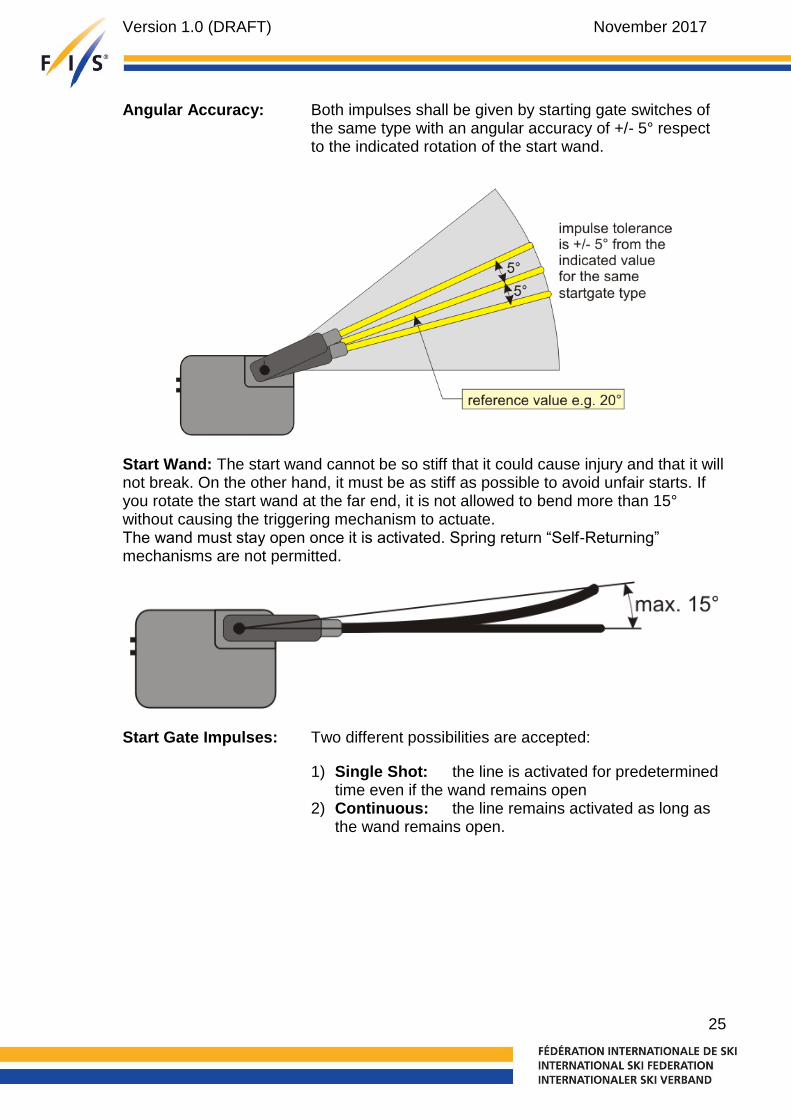
Angular Accuracy: Both impulses shall be given by starting gate switches of the same type with an angular accuracy of +/- 5° respect to the indicated rotation of the start wand.
Start Wand: The start wand cannot be so stiff that it could cause injury and that it will not break. On the other hand, it must be as stiff as possible to avoid unfair starts. If you rotate the start wand at the far end, it is not allowed to bend more than 15° without causing the triggering mechanism to actuate. The wand must stay open once it is activated. Spring return “Self-Returning” mechanisms are not permitted.
Start Gate Impulses: Two different possibilities are accepted:
1) Single Shot: the line is activated for predetermined time even if the wand remains open
2) Continuous: the line remains activated as long as the wand remains open.
Version 1.0 (DRAFT) November 2017
26
6.3. Photocell
6.3.1. Installation
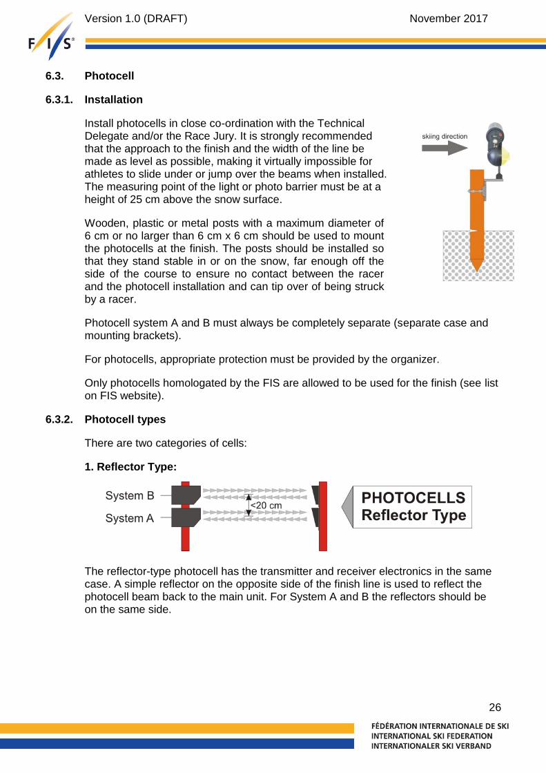
Install photocells in close co-ordination with the Technical Delegate and/or the Race Jury. It is strongly recommended that the approach to the finish and the width of the line be made as level as possible, making it virtually impossible for athletes to slide under or jump over the beams when installed. The measuring point of the light or photo barrier must be at a height of 25 cm above the snow surface.
Wooden, plastic or metal posts with a maximum diameter of 6 cm or no larger than 6 cm x 6 cm should be used to mount the photocells at the finish. The posts should be installed so that they stand stable in or on the snow, far enough off the side of the course to ensure no contact between the racer and the photocell installation and can tip over of being struck by a racer.
Photocell system A and B must always be completely separate (separate case and mounting brackets).
For photocells, appropriate protection must be provided by the organizer.
Only photocells homologated by the FIS are allowed to be used for the finish (see list on FIS website).
6.3.2. Photocell types
There are two categories of cells:
1. Reflector Type:
The reflector-type photocell has the transmitter and receiver electronics in the same case. A simple reflector on the opposite side of the finish line is used to reflect the photocell beam back to the main unit. For System A and B the reflectors should be on the same side.
Version 1.0 (DRAFT) November 2017
27
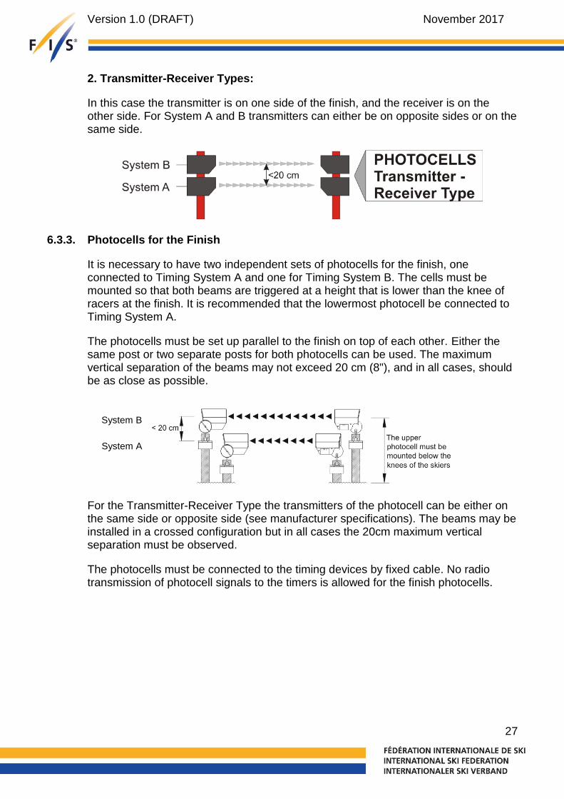
2. Transmitter-Receiver Types:
In this case the transmitter is on one side of the finish, and the receiver is on the other side. For System A and B transmitters can either be on opposite sides or on the same side.
6.3.3. Photocells for the Finish
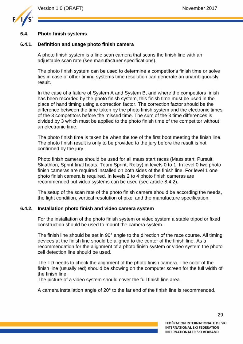
It is necessary to have two independent sets of photocells for the finish, one connected to Timing System A and one for Timing System B. The cells must be mounted so that both beams are triggered at a height that is lower than the knee of racers at the finish. It is recommended that the lowermost photocell be connected to Timing System A.
The photocells must be set up parallel to the finish on top of each other. Either the same post or two separate posts for both photocells can be used. The maximum vertical separation of the beams may not exceed 20 cm (8"), and in all cases, should be as close as possible.
For the Transmitter-Receiver Type the transmitters of the photocell can be either on the same side or opposite side (see manufacturer specifications). The beams may be installed in a crossed configuration but in all cases the 20cm maximum vertical separation must be observed.
The photocells must be connected to the timing devices by fixed cable. No radio transmission of photocell signals to the timers is allowed for the finish photocells.
System B
System A

Version 1.0 (DRAFT) November 2017
28
6.3.4. Technical Specifications for the Photocell
The technical concept of the photocell is not restricted by the FIS, although it must be assured that the photocell cannot be influenced by any other light, camera flash/strobes, radio waves (EMI) or mobile reflectors for photocells of reflector type.
The photocell must meet the standards for electronic devices in the country that it is sold.
Accuracy: Sensing Time - The time delay from the instant the photocell is triggered to moment an output impulse is generated may not exceed 0.005 sec. Repeatability (Random Jitter) - The delay of impulses must be constant, the range must be less than 5/10.000 sec. This range is measured in a “peak-to-peak” manner, minimum to maximum extremes, it is not averaged.
Operating Distance: The photocell must work over a minimal distance of 20 m. The maximum size of the reflector (if used) is 100 mm (in all directions)
Triggering Object: An 8 mm object moving with a speed of 10 km/h is not allowed to trigger the photocell (measured at a distance of 2 m from lens of the receiver). A 100 mm object moving with a speed of 200 km/h must trigger the photocell (measured at a distance of 2 m from lens of the receiver).
Temperature Range: -20 to +60°C (for colder weather you should prepare a cover so the photocell will still work).
Power Supply: If the photocell is supplied power from the timing device (within the same cable as the impulses) it needs no external power supply. If a battery is used as the power supply (external or internal) the Photocell must work for four (4) hours at -20°C.
Delay trigger A delay trigger (blocking time) of the photo cell should be set according manufacture specification.
For homologation of photocells:
When sending photocells to the FIS for homologation, the photocell needs an input contact to switch the photocell transmitter off, in order to make precise tests.
Version 1.0 (DRAFT) November 2017
29
6.4. Photo finish systems
6.4.1. Definition and usage photo finish camera
A photo finish system is a line scan camera that scans the finish line with an adjustable scan rate (see manufacturer specifications).
The photo finish system can be used to determine a competitor’s finish time or solve ties in case of other timing systems time resolution can generate an unambiguously result.
In the case of a failure of System A and System B, and where the competitors finish has been recorded by the photo finish system, this finish time must be used in the place of hand timing using a correction factor. The correction factor should be the difference between the time taken by the photo finish system and the electronic times of the 3 competitors before the missed time. The sum of the 3 time differences is divided by 3 which must be applied to the photo finish time of the competitor without an electronic time.
The photo finish time is taken be when the toe of the first boot meeting the finish line. The photo finish result is only to be provided to the jury before the result is not confirmed by the jury.
Photo finish cameras should be used for all mass start races (Mass start, Pursuit, Skiathlon, Sprint final heats, Team Sprint, Relay) in levels 0 to 1. In level 0 two photo finish cameras are required installed on both sides of the finish line. For level 1 one photo finish camera is required. In levels 2 to 4 photo finish cameras are recommended but video systems can be used (see article 8.4.2).
The setup of the scan rate of the photo finish camera should be according the needs, the light condition, vertical resolution of pixel and the manufacture specification.
6.4.2. Installation photo finish and video camera system
For the installation of the photo finish system or video system a stable tripod or fixed construction should be used to mount the camera system.
The finish line should be set in 90° angle to the direction of the race course. All timing devices at the finish line should be aligned to the center of the finish line. As a recommendation for the alignment of a photo finish system or video system the photo cell detection line should be used.
The TD needs to check the alignment of the photo finish camera. The color of the finish line (usually red) should be showing on the computer screen for the full width of the finish line. The picture of a video system should cover the full finish line area.
A camera installation angle of 20° to the far end of the finish line is recommended.
Version 1.0 (DRAFT) November 2017
30
6.4.3. Technical Specifications for the photo finish camera
All photo finish systems must meet the following criteria for use in FIS Cross-Country races:
Timer: The timer must be able to operate in Time-of-Day mode and be synchronized with all timing devices.
Operation Temperature: The photo finish camera must operate (once it is started) at ambient temperatures from -10° to +40°C
Measuring Range: Time of day mode must be possible in hours, minutes, seconds and 1/1000, or better.
Timer Precision: Must measure up to 1/10000 second in time of day Timer accuracy must be below +/- 10 PPM) at a device temperature from –10° to +60°C.
Quartz: Ageing of the quartz must be below +/- 3 PPM per year. With adjusted quartz frequency the time drift must be below +/-0.5 PPM at 23°C.
Impulse Triggering: The delay of impulses is not allowed to be higher than 1/1000 sec. for the same channel (the channel is triggered from a reference impulse device in minute intervals). The delay of impulses must be constant; the range must be less than 1/10000 sec.
Timing Channels: The timing device needs a minimum of one timing channel for time of day synchronization.
Image Production: The photo finish system must scan the finish line at a minimum of 2000 scans per second and show images sequentially and show scanned finish line images in sequential order on a monitor screen and store it on a memory device.
Image Evaluation: The photo finish system must be capable of showing the time of day for each line scan image.
Power Supply: Backup power supply must be granted for a minimum of 20 minutes (e.g. internal battery or external UPS).

Version 1.0 (DRAFT) November 2017
31
Electromagnetic: The timing device must meet the standards of IEC (International Electronic Commission). This means the timing device must function satisfactorily in its electromagnetic environment without introducing intolerable electromagnetic disturbances to anything in that environment.
6.5. Start clock
A Start clock is a device that helps the starter to organize the start. Use of such a start clock is highly recommended for all individual start and pursuit disciplines and is mandatory for use at event Levels 1 and 0. The start clock indicates the start gap 3 sec. before and after the start signal (Level 0). It must work in time of day mode.
Homologation is necessary starting from season TBD.
6.5.1. Technical Specifications for the start clock (only interval start)
Display The start clock has a visible display to the athletes. The display can be analog or digital. Analogue Clock: The clock must be visible over a distance of at least 10 m Digital Clock: The figures must be visible over a distance of at least 10 m Time of day: hours, minutes and seconds (min. 3 digit) Countdown: minutes and seconds (min. 3 digit) Bib: to show the bib is not mandatory, but can be an option
Start indicator light: The start clock must show if the start is free (green indicator) or not allowed (red indicator).
Acoustic Countdown: The start clock needs an acoustic countdown. The acoustic countdown has at least one beep at each second during the last five seconds (low tone from five seconds to 1 second and high tone at zero).
Countdown: The start clock needs to support each start interval used on the start list.
Interface: The start clock needs an interface (e.g. RS232, RS422, USB, Ethernet or wireless) to connect a PC or other suitable device and transfer the data to the start clock.

Version 1.0 (DRAFT) November 2017
32
Power Supply: The start clock must work without power supply from the mains for eight (8) hours at 23°C. The start clock must work without external power supply on internal batteries for 6 (six) hours at -20°C.
Operation Temperature: The start clock must work at ambient temperatures from -20° to +60°C*
Measuring Range: Time of day mode must be possible.
Timer: The timer must be able to operate in Time-of-Day mode and be synchronized with all timing devices.
Timer Precision: Must measure up to 1/1000 second in time of day mode. Timer accuracy must be below +/- 10 PPM at a device temperature from –20° to +60°C.
Quartz: Ageing of the quartz must be below +/- 3 PPM per year. With adjusted quartz frequency the time drift must be below +/-0.5 PPM at 23°C.
Impulse Triggering: The delay of impulses is not allowed to be higher than 1/1000 sec. for the same channel (the channel is triggered from a reference impulse device in minute intervals). The delay of impulses must be constant; the range must be less than 1/10000 sec.
Timing Channels: The timing device needs a minimum of two timing channels. One is for synchronization and one for output of the start impulse (zero tone, e.g. to start the timing device).
Synchronization: Synchronization with other timing devices must be possible.
Electromagnetic: The timing device must meet the standards of IEC (International Electronic Commission). This means the timing device must function satisfactorily in its electromagnetic environment without introducing intolerable electromagnetic disturbances to anything in that environment.

Version 1.0 (DRAFT) November 2017
33
6.5.2. Cross Country Individual start
The start clock shows the time of day and a countdown to the next start. The official start time is given by an acoustic start signal. Additionally, the start clock can indicate with colored indicator lights (e.g. green, red) the start time corridor (3 sec. before to 3 sec. after official start time) and gives a 5 second acoustic countdown signals. Acoustic start and countdown signals should be different in length or kind of sound.
6.5.3. Cross Country Handicap start
The handicap start is carried out without an electronic start gate. A video camera should be used to record the entire start such that a review by the Jury can be done. The video camera should record the start and time of day of a display clock. In order to guarantee an exact start, a large display clock must be used for each starting lane together with bib number and starting times for respective competitors for that lane. The start must be prepared so that two or more competitors may start side by side.
6.5.4. Nordic Combined Gundersen start
The Gundersen start is carried out without an electronic start gate. In order to guarantee an exact start, a large display digital clock must be used. The clock is started by zero time when the first competitor starts. At the same time, the starters must start an additional stop watch for control. The starting procedure must be recorded by a HD video camera which focused to the clearly marked starting line (see marking finish line, art. 515.2.18). As a backup system for OWG, WSC and WC an additional transponder line has to be placed 1,5 m beyond the starting line. The reference time for the Jury to check the start procedure is 1 second, which means all earlier starts must be checked.
Version 1.0 (DRAFT) November 2017
34
7. Other timing support systems
7.1. Transponder system
The transponder system installation has to be done according the manufacture
instructions.
Transponders (active systems) can be used as a supporting system to the official
timing system to determine race times and ranking sequences at intermediate timing
points, pre-timing points and finish (unofficial result).
The official result has always to be confirmed by using a FIS homologated timing system.
7.2. Start system
7.2.1. Electronic start gun/system
When the starter presses the button of the electronic start gun, they emit a signal to play a simulated gunshot or other acoustic start signal that is broadcasted to loudspeakers close to the start lanes, can show a flash (optional) and sends an electronic start impulse to the timing system. The start system must be installed so that every competitor at the start can hear the acoustic start signal loud and clear at the same time.
7.2.2. Noise detector for start guns
A noise detection sensor is affixed to a regular start gun, which sends an electronic start impulse to the timing system upon firing.
7.3. Heat start gate
Electronic or mechanical start gate by start lane with optical indication of a false start either on the gate or control interface. The usage in level 0 in mandatory.
Version 1.0 (DRAFT) November 2017
35
7.3.1. Start gates with photo cells

Version 1.0 (DRAFT) November 2017
36
7.3.2. Start gate with wand

Version 1.0 (DRAFT) November 2017
37
7.4. Video control system
A video control system is video camera system which records picture by picture. It is recommended to use HD video cameras with at least 100 frames per seconds or higher. Video systems are not subjects to be homologated as timing device.
7.4.1. Start
Cross-Country Handicap Start:
A video camera should be used to record the entire start such that a review by the
Jury can be done.
To support the recording of the start procedure a start clock can be set up so that the
video control system also records the display with the reference time.
Nordic Combined Gundersen Start:
The starting procedure must be recorded by a HD video camera which focused to the
clearly marked starting line (see marking finish line, art. 515.2.18).
To support the recording of the start procedure a start clock can be set up so that the
video control system also records the display with the reference time.
7.4.2. Finish
The video system can be used in order to determine the order and starting bibs at the finish line or to solve tie. For determination of the competitor’s finish time a homologated timing device has to be used.
Nordic Combined
The finish is to be recorded by two video cameras. The first camera must be positioned on one the side of the finish line providing a picture of the finish and an additional camera positioned to identify the starting bibs.
Version 1.0 (DRAFT) November 2017
38
8. Timing without cable connection between start and finish
The FIS Timing Working Group recognizes the importance of allowing emerging and technically responsible technologies to be used in modern FIS events. For this reason, and because of the flexibility that it affords, FIS Level 1 to4 events may use timing solutions that do not require any hard wire connection between start and finish for either A and/or B systems. Level 0 events are not allowed to use this solution.
Regardless of the technology being used, every solution without cable connection to start and finish must include the use of 4 homologated timers operating in synchronized Time-of-Day with active printers. System A will be represented by one timer at the start and one timer at the finish. One timer at the start and one timer at the finish will represent system B.
All timing rules remain in force in this situation (set-up, synchronization, time-of day precision, printing, hand timing). In addition, the Timing Technical Report has to be sent as XML file to FIS office and approved by the TD that the race result gets valid.
The Chief of Timing must make certain that all timers and printers work in the physical environment of the start and finish regardless of the weather conditions and temperature particularly if the temperature is expected to be less than –20° C.
When a radio system with impulse transmission is used, every start time transmitted has a delay. This delay must be constant within +/- 1/1000 second. The delay must be clearly described in the manual of the radio system. Apply the FIS rules if a time from system B is used.
This allows race organizers to use many types of timing solutions without wires as long as these 4 timers are in place and are used to verify the results. If times are generated by a timing solution other than system A or B in all cases these times must be checked against system A and must match exactly. In case results deviate from system A, the events must be evaluated on the A system times as per the normal timing set-up rules and procedures.
Please refer to the set-up diagram that illustrates the correct use of this technique.

Version 1.0 (DRAFT) November 2017
39
9. Set up drawings
9.1. Level 0 – Individual / Sprint Qualification Start

Version 1.0 (DRAFT) November 2017
40
9.2. Level 0 – Sprint Final

Version 1.0 (DRAFT) November 2017
41
9.3. Level 0 – Mass Starts

Version 1.0 (DRAFT) November 2017
42
9.4. Level 0 – Pursuit / Gundersen Start

Version 1.0 (DRAFT) November 2017
43
9.5. Level 1-4 – Individual / Sprint Qualification Start

Version 1.0 (DRAFT) November 2017
44
9.6. Level 1-4 – Sprint Final 9.6.1. Timer A + B, Photo Cells A + B, Photo finish
START
FINISH
Start Operator
Cross Country trackStart-Gates (optional)
Startgun
Videoreplay
1 pair
1 pair
to Timing room
min. 2 pairs
(gun+detector, electronic gun
or start signal system)
Photo Cells(transmitter & receiver or reflector type)
(time of day
synchronized)
manual timer(time of day synchronized)
with printer
to Timing room (optional)
TIMER A TIMER BPhotofinish A
to Timing room
(optional)
manual timer(time of day synchronized)
with printer
(optional)
Photo Finish or
Video Finish
FINISH LINE
each 1 pair
(all components time of day synchronized)
FEDERATION INTERNATIONALE DE SKI
Cross Country SkiingTiming System Level 1-4
Timer A / B + Photo Cells A / B +Photo or Video Finish
Drawn by
Date
Proved by
File name
05.06.2017
Swiss Timing
CC_TSC_level1-4.dwg
Swiss Timing / Mis
VersionSprint Final's
CC-FIS-Lv1-4 / SF 1
V005/SF1

Version 1.0 (DRAFT) November 2017
45
9.6.2. Timer A, Photo Cells A, Photo finish
Start Operator
Start-Gates (optional)
Startgun
to Timing room
min. 2 pairs
(gun+detector, electronic gun
or start signal system)
Photo Cells(transmitter & receiver or reflector type)
(time of day
synchronized)
manual timer(time of day synchronized)
with printer
to Timing room (optional)
TIMER A
to Timing room
(optional)
manual timer(time of day synchronized)
with printer
FINISH LINE
each 1 pair
Photofinish (Timer B)
(all components time of day synchronized)
1 pair
1 pair
Photo Finish
FEDERATION INTERNATIONALE DE SKI
Cross Country SkiingTiming System Level 1-4
Drawn by
Date
Proved by
File name
05.06.2017
Swiss Timing
CC_TSC_level1-4.dwg
Swiss Timing / Mis
VersionSprint Final'sTimer A + Photo Cells A +Photo Finish
CC-FIS-Lv1-4 / SF 2
V005/SF2
FINISH
START
Cross Country track

Version 1.0 (DRAFT) November 2017
46
9.6.3. Photo finish A + B
FINISH
Start Operator
Start-Gates (optional)
Startgun
to Timing room
min. 2 pairs
(gun+detector, electronic gun
or start signal system)
manual timer(time of day synchronized)
with printer
to Timing room (optional)
to Timing room
(optional)
manual timer(time of day synchronized)
with printer
FINISH LINE
(all components time of day synchronized)
1 pair
1 pair
Photofinish (Timer A) Photofinish (Timer B)
(all components time of day synchronized)
Photo Finish APhoto Finish B
FEDERATION INTERNATIONALE DE SKI
Cross Country SkiingTiming System Level 1-4
Drawn by
Date
Proved by
File name
05.06.2017
Swiss Timing
CC_TSC_level1-4.dwg
Swiss Timing / Mis
VersionSprint Final'sPhoto Finish A / B
V005/SF3
CC-FIS-Lv1-4 / SF 3
START
Cross Country track
Version 1.0 (DRAFT) November 2017
47
9.7. Level 1-4 – Mass Starts 9.7.1. Timer A + B, Photo cells A + B, Photo finish
FINISH
Start Operator
1 pair
1 pair
to Timing room
min. 2 pairs
Startgun(gun+detector, electronic gun
or start signal system)
Videoreplay
Photo Cells(transmitter & receiver or reflector type)
TIMER A TIMER B
(time of day
synchronized)
(all components time of day synchronized)
Photofinish A
to Timing room
(optional)
manual timer(time of day synchronized)
with printer
manual timer(time of day synchronized)
with printer
to Timing room (optional)
(optional)
each 1 pair
FINISH LINE
Photo Finish or
Video Finish
FEDERATION INTERNATIONALE DE SKI
Cross Country SkiingTiming System Level 1-4
Timer A / B + Photo Cells A / B +Photo or Video Finish
Drawn by
Date
Proved by
File name
05.06.2017
Swiss Timing
CC_TSC_level1-4.dwg
Swiss Timing / Mis
VersionMass Start's
V005/MS1
CC-FIS-Lv1-4 / MS 1
START
Cross Country track
Version 1.0 (DRAFT) November 2017
48
9.7.2. Timer A. Photo cells A, Photo finish
FINISH
Start Operator
Startgun
to Timing room
min. 2 pairs
(gun+detector, electronic gun
or start signal system)
Photo Cells(transmitter & receiver or reflector type)
(time of day
synchronized)
manual timer(time of day synchronized)
with printer
to Timing room (optional)
TIMER A
to Timing room
(optional)
manual timer(time of day synchronized)
with printer
FINISH LINE
each 1 pair
Photofinish (Timer B)
(all components time of day synchronized)
1 pair
1 pair
Photo Finish
FEDERATION INTERNATIONALE DE SKI
Cross Country SkiingTiming System Level 1-4
Drawn by
Date
Proved by
File name
05.06.2017
Swiss Timing
CC_TSC_level1-4.dwg
Swiss Timing / Mis
VersionMass Start'sTimer A + Photo Cells A +Photo Finish
CC-FIS-Lv1-4 / MS 2
V005/MS2
START
Cross Country track

Version 1.0 (DRAFT) November 2017
49
9.7.3. Photo finish A + B
FINISH
Start Operator
Startgun
to Timing room
min. 2 pairs
(gun+detector, electronic gun
or start signal system)
manual timer(time of day synchronized)
with printer
to Timing room (optional)
to Timing room
(optional)
manual timer(time of day synchronized)
with printer
FINISH LINE
(all components time of day synchronized)
1 pair
1 pair
Photofinish (Timer A) Photofinish (Timer B)
(all components time of day synchronized)
Photo Finish APhoto Finish B
FEDERATION INTERNATIONALE DE SKI
Cross Country SkiingTiming System Level 1-4
Drawn by
Date
Proved by
File name
05.06.2017
Swiss Timing
CC_TSC_level1-4.dwg
Swiss Timing / Mis
VersionMass Start'sPhoto Finish A / B
V005/MS3
CC-FIS-Lv1-4 / MS 3
START
Cross Country track

Version 1.0 (DRAFT) November 2017
50
9.8. Level 1-4 – Pursuit / Gundersen Start 9.8.1. Timer A + B, Photo cells A + B, Photo finish
FINISH
1 2 3 W
3-5 lanes + Wave start lane
Start Clock(time of day
synchronized)
Startlanes
Video replay(time of day synchronized)
Videoreplay
Photo Cells(transmitter & receiver or reflector type)
FINISH LINE
TIMER A TIMER B
(time of day
synchronized)
(all components time of day synchronized)
Photofinish
to Timing room
(optional)
manual timer(time of day synchronized)
with printer
(optional)
Start
manual timer(time of day synchronized)
Operator
with printer
to Timing room (optional)
(for NC required)
(for CC optional)
each 1 pair
Photo Finish or
Video Finish
FEDERATION INTERNATIONALE DE SKI
Cross Country SkiingTiming System Level 1-4
PursuitTimer A / B + Photo Cells A / B +Photo or Video Finish
Drawn by
Date
Proved by
File name
05.06.2017
Swiss Timing
CC_TSC_level1-4.dwg
Swiss Timing / Mis
CC-FIS-Lv1-4 / PU 1
V005/PU1Version
START
Cross Country track
Version 1.0 (DRAFT) November 2017
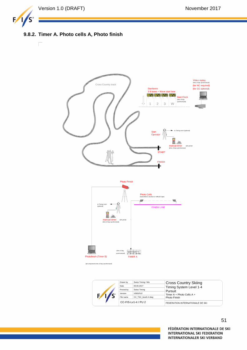
51
9.8.2. Timer A. Photo cells A, Photo finish
FINISH
Photo Cells(transmitter & receiver or reflector type)
(time of day
synchronized)
TIMER A
to Timing room
(optional)
manual timer(time of day synchronized)
with printer
FINISH LINE
Photofinish (Timer B)
(all components time of day synchronized)
Photo Finish
1 2 3 W
3-5 lanes + Wave start lane
Start Clock(time of day
synchronized)
Startlanes
Video replay(time of day synchronized)
Start
manual timer(time of day synchronized)
Operator
with printer
to Timing room (optional)
(for NC required)
(for CC optional)
FEDERATION INTERNATIONALE DE SKI
Cross Country SkiingTiming System Level 1-4
Pursuit
Drawn by
Date
Proved by
File name
05.06.2017
Swiss Timing
CC_TSC_level1-4.dwg
Swiss Timing / Mis
VersionTimer A + Photo Cells A +Photo Finish
V005/PU2
CC-FIS-Lv1-4 / PU 2
START
Cross Country track

Version 1.0 (DRAFT) November 2017
52
9.8.3. Photo finish A + B
FINISH
to Timing room
(optional)
manual timer(time of day synchronized)
with printer
FINISH LINE
(all components time of day synchronized)
Photofinish (Timer A) Photofinish (Timer B)
(all components time of day synchronized)
Photo Finish APhoto Finish B
1 2 3 W
3-5 lanes + Wave start lane
Start Clock(time of day
synchronized)
Startlanes
Video replay(time of day synchronized)
Start
manual timer(time of day synchronized)
Operator
with printer
to Timing room (optional)
(for NC required)
(for CC optional)
FEDERATION INTERNATIONALE DE SKI
Cross Country SkiingTiming System Level 1-4
Pursuit
Drawn by
Date
Proved by
File name
05.06.2017
Swiss Timing
CC_TSC_level1-4.dwg
Swiss Timing / Mis
Version V005/PU3
CC-FIS-Lv1-4 / PU 3
Photo Finish A / B
START
Cross Country track

Version 1.0 (DRAFT) November 2017
53
9.9. Level 1-4 – Individual Start (wireless)

Version 1.0 (DRAFT) November 2017
54
9.10. Level 1-4 – Mass Start (wireless)

Version 1.0 (DRAFT) November 2017
55
10. Important ICR rules for Timing in Cross-Country
218.1.1 Transmission of Results For all international competitions, there must be direct communication between the Start and the Finish. In Olympic Winter Games the communications must be assured by fixed wiring.
315.2 Interval Start Procedure 315.2.1 Interval starts will normally use half -minute intervals and fifteen seconds
for sprint qualifying round. The Jury may approve shorter or longer intervals.
315.2.2 The start command consists of a countdown starting 5 seconds before the start time ("5-4-3-2-1") and start signal ("GO!"). The command can be given verbally or by audible signals.
315.2.4 The competitor may start any time between three seconds before three seconds after the start signal. If he/she starts more than three seconds before the start signal, it is a false start. If he/she starts more than three seconds after the start signal, it is late start and the start list time will count.
315.2.6 With both electric and hand-timing, the competitor's actual start time must be noted in case the Jury decides his late start was due to force majeure.
315.3.2 The starting procedures for a Mass Start will begin two minutes before the start signal. At this time instructions about the start will be given to all competitors assembled in their start lanes. These instructions should end with the competitors being instructed to stand at their start positions and a “one minute to start warning” is given. Next there will be the command “30 seconds to start”. When all competitors are motionless then the next sound will be the start command or signal.
315.4.3 The handicap start is carried out without an electronic start gate. A video camera should be used to record the entire start such that a review by the Jury can be done.
315.4.4 In order to guarantee an exact start, a large display clock must be used for each starting lane together with bib number and starting times for respective competitors for that lane. The start must be prepared so that two or more competitors may start side by side.
315.5.2 Electronic and/or mechanical start gates can be used if approved by the Jury.

Version 1.0 (DRAFT) November 2017
56
315.5.3 Competitors are organized on the pre-start line where instructions are given and start lanes designated. The starter will give the command “take your start positions” and the competitors advance to the start line. When all competitors are at the start line, the starter will give the command “Set” and all the competitors must remain motionless until the starter gives the start signal.
315.7.2 For all competitions using a mass start or heat start procedure, any false start will result in a “restart” of the competition. The starter or the start gate must give a false start signal. There must be assistants placed an effective distance down the tracks where it is possible to turn the competitors back.
316 Timing 316.1 For all competitions listed in the FIS Calendar, electronic timekeeping
must be used. Electronic timing will always be supplemented by hand-timing as a backup system and the results cross-checked between the two systems.
316.2 If the electronic timing temporarily fails hand times will be used by correcting the average time difference which develops between the electronic timing and the hand-timing. If the electronic timing fails frequently or completely during the competition, the hand times will be used for all the competitors. When hand times are used to calculate results, the actual start times must be used.
316.3 When using hand-timing, the time is taken when the competitor's first foot crosses the finish line.
316.4 Electronic Timing 316.4.1 The following electronic timing technologies can be used to identify the
official finish times:
Electronic timing system based on photo cells. The measuring point of the light or photo barrier must be at a height of 25 cm above the snow surface.
Photo finish system. The measuring point will be the toe of the first boot meeting the finish line
316.4.2 Transponder Timekeeping Transponders (active systems) can be used as a supporting system to the official timing system to determine race times and ranking sequences at intermediate timing points, pre-timing points and finish (unofficial result).The official result has always to be confirmed by using a electronic timing system in accordance to ICR 316.4.1.
316.5 In the case of competitors falling as they cross the finish line, the competitors will be assigned their finish time as per articles 316.3 or 316.4 if all the parts of their bodies are moved across the finish line without any outside assistance.
Version 1.0 (DRAFT) November 2017
57
316.6 For the calculation of results all start and finish times will be recorded to at least 1/100 (0.01) precision. The calculated net time for each competitor is determined by subtracting the recorded start time from the recorded finish time. The final result for each skier will be determined to 1/10 (0.1) precision by truncating the calculated net time. For example, 38:24.38 becomes 38:24.3.
316.7 During the OWG, WSC, JWSC and WC, photo finish cameras must be used.
316.8 The finish referee is responsible for keeping a list of the order in which the competitors cross the finish line. He gives this list to the chief of timekeeping and data processing.
317 Results 317.1 Calculation of Results 317.1.1 The results are calculated by taking the difference between the finish and
start times. In a stage event competition, the actual time, bonus seconds and time penalties from each stage are accumulated.
317.1.2 The ranking of athletes involved in a photo finish will be established according to the order they crossed the vertical plane of the finish line by the toe of the front foot.
324.5 Timing and Results (Pursuit) 324.5.1 The calculation of the final times in a pursuit competition will be done by
combining the results (actual skiing time) in the previous race without the tenths of a second with the final results of the second race with the tenths of a second. For competitors that use the handicap start method the order of finish determines the final ranking.
325.4.1 Qualification (Sprint) 325.4.1.1 Interval Start procedure must be used (see ICR Art. 315.2). Start intervals
can be 10, 15, 20 or 30 seconds.
325.5 Timing and results (Sprint) 325.5.1 For OWG, WSC, JWSC and WC sprint qualifying round and heats, start
and finish times are recorded to 1/1000 precision and the final result is determined to 1/100 precision. For other FIS sprint competitions, it is possible to use timing equipment that only has 1/100 precision but still the final results report the hundredths of a second.
326.5 Timing and results (Team Sprint) 326.5.1 For OWG, WSC, JWSC and WC team sprint semi-finals and finals, start
and finish times are recorded to 1/1000 precision and the final result is determined to 1/100 precision. For other FIS sprint competitions, it is possible to use timing equipment that only has 1/100 precision but still the final results report the hundredths of a second.
Version 1.0 (DRAFT) November 2017
58
327.5 Timing and Results (Relay) 327.5.1 Intermediate times for the individual legs of the course are taken when the
competitor crosses the line for the intermediate timing. This is also the starting time for the next competitor.
327.5.2 The total time of a relay team is the time which elapses between the start and team's final competitor crossing the finish line. The order in which the competitors finish the last relay leg determines the result list.
343.5 If transponders or GPS are used it is mandatory for the competitors to wear this equipment.
344.4 Wax testing and warming up on the ski competition course must always be done in the competition course direction. Anyone testing skis on the competition course must consider the safety of others on the course and the course preparation. Electronic timing devices used for testing skis will not be allowed on the course during the competition or official training.
11. Important ICR rules for Timing in Nordic Combined (Cross-Country)
504.2.2 Finish Referee The finish referee is responsible for keeping a list and a voice recorder (dictaphone) of the order in which the competitors cross the finish line. He gives this list and the tape to the chief of timekeeping.
513.2.6 Timekeeping Building Timekeeping and calculation should be located in a building with a good view of the start and finish.
514.2 Measuring Devices for Cross-Country For all competitions listed in the FIS Calendar, electronic timekeeping is mandatory. Electronic timing will always be supported by hand timing as a backup system and the results cross checked between the two systems.
514.2.1 Timekeeping – Start The Gundersen start is carried out without an electronic start gate. In order to guarantee an exact start, a large display digital clock must be used. The clock is started by zero time when the first competitor starts. At the same time, the starters must start an additional stop watch for control. The starting procedure must be recorded by a HD video camera which focused to the clearly marked starting line (see marking finish line, art. 515.2.18). As a backup system for OWG, WSC and WC an additional transponder line has to be placed 1,5 m beyond the starting line. The reference time for the Jury to check the start procedure is 1 second, which means all earlier starts must be checked.
514.2.2 Intermediate Time An intermediate timing point will be established according to the local circumstances and the respective length of the course. In principle, it

Version 1.0 (DRAFT) November 2017
59
should be 1 – 2 intermediate timing points per round.
514.2.3 Finish Timing Times will be measured in full tenths of a second. Times to one hundredth of a second will not be used. When using hand timing, the time is taken when the competitor's first foot crosses the finish line. In case of electronic timing, the time is taken when the contact is broken. The measuring point of the light or photo barrier must be at a height of 25 cm above the snow surface. Additionally, the finish is to be recorded by video cameras. The first camera must be positioned on one the side of the finish line providing a picture of the finish and an additional camera positioned to identify the starting bibs.
514.2.4 At OWG, WSC and WC-NC special Photo-Finish cameras (Line-CCD) must be employed to record the correct order of finish. To attain a correct and swift result evaluation, it is imperative that every competitor wears an additional starting bib on the outside of his thigh where the camera position is. The height of the starting bib digits should not be less than 8 cm. The Line-CCD camera must be able to register finish line crossing with a 1/1000 s precision. The CCD camera must be synchronised with the main timing system 1/2 hour before competition starts. The display of the time behind the winner or display of the running time is sufficient. In the case of Photo-Finish decisions, the image of the Line-CCD camera must be presented on the system monitor to the Jury, additionally a colour print-out with time scale is required. This system is subject to FIS homologation.
514.2.5 Photo Finish The use of technical measurements (Video camera, Line-CCD camera) shall be used in the following situations for the determination of the actual final ranking:
if the finishing times are identical
a difference in the finish ranking list made by the finish referees
the difference between two or more athletes crossing the finish cannot be clearly witnessed.
514.3 Transponder Timekeeping Transponders (active systems) can be used as a supporting system to the official timing system to determine race times and ranking sequences at intermediate timing points, pre-timing points, and finish (unofficial result). The official result must be confirmed by using electronic timing systems in accordance with ICR 514.3.1. For Gundersen competitions the order at the finish is the ranking criteria for the official result. The finish order must be confirmed in any case with the photo finish system. In case of usage of transponders, the determined finish times can be used for the official result when the finish order is confirmed by photo finish system.
514.3.1 Electronic Timing The following electronic timing technologies can be used to identify the
Version 1.0 (DRAFT) November 2017
60
official finish times:
Electronic timing system based on photo cells. The measuring point of the light or photo barrier must be at a height of 25 cm above the snow surface.
Photo finish system. The measuring point will be the toe of the first boot meeting the finish line.
515.2.7 Start Area The start must be prepared according to the terrain, with the first 100–200 m prepared to a width at 6–9 m. In order to guarantee an exact start, a large digital clock and a board with the starting numbers and starting times for each starting lane must be used. The clock is started by zero time when the first competitor starts. At the same time, the starters have to start an additional stop watch for control. An additional assistant is responsible to control the lane start boards by crossing off the names of the competitors after they have started.
542 Team Gundersen Competition 542.2 Calculation
The calculation is based on the appropriate meter and point value according the art. 527.2.3.2 and 527.4.1. For the final result list the ranking must be fixed, if necessary with technical help. In case of two or more athletes arriving at the finish line with the identical times a decision is made by the use of the photo finish video or by finish referee (art. 514.2.5). In case when no visual differences between competitors can be determined with the assistance of the technical equipment, the same rank will be given in the final result. For cup competitions, the same points will be awarded. The start differences for the Cross-Country race will be calculated from the actual total points scored by each team from the Jump event.
543 Team-Sprint 543.2 Calculation
The calculation is based on the appropriate meter and point value according to the art. 527.2.3.2 and 527.4.1. For the final result list the ranking must be fixed, if necessary with technical help. In case of two or more athletes arriving at the finish line with the identical times a decision is made by the use of the photo finish video or by finish referee (art. 514.2.5). In case when no visual differences between competitors can be determined with the assistance of the technical equipment, the same rank will be given in the final result. For cup competitions, the same points will be awarded. The calculation of the jumping result is the actual total points scored by both jumps for each team and will be used for the starting differences of the Cross-Country race.

Version 1.0 (DRAFT) November 2017
61
12. Homologation of Timing Equipment
Manufacturers wishing to have their timing devices, start gate, photocells or photo finish system homologated for use in FIS races must send a request to the Timing Working Group through the FIS office which will instruct the manufacturer to provide all technical information indicated above. Software for photo finish systems are not part of the homologation. The costs of homologation have to be paid by the manufacturer.
13. List of Homologated Timing Equipment
The List of homologated timing equipment is not included in the timing booklet. Please check this list on FIS webpage in the Timing / Data section.

Version 1.0 (DRAFT) November 2017
62
14. Conclusion
We hereby wish to thank all members of the "FIS Timing Working Group" who have always used every endeavor to realize this "FIS GUIDE" for their Technical Delegates and event organizers. Our progress since 1996 reflects the balance between accepting new technologies and ensuring the correct evaluation of human performance through fundamental timekeeping concepts.
We wish to acknowledge the major contributions of participating manufacturers, FIS professionals and volunteers from our many member National Associations and race organizers who give so much of their time and expertise without which it would be impossible to generate such a document or perspective.
The FIS is pleased to support such a unique group in the world of timekeeping regulation and notices the absence of similar structures in many other high-performance sports that rely so heavily on timing technology for fair and impartial judgement.
We are fully aware that there are still some imperfections in these rules and descriptions and would welcome any constructive proposal as the works proceed. This document will be continually revised to improve the knowledge of the FIS community for the benefit of all competitions.
Please contact us with your suggestions and comments:
Daniel Defago (FIS) [email protected] Ulf Seehase (FIS) [email protected] Maria Martin Civiac (FIS) [email protected] Blanchard, Raphaël (SUI) [email protected] Ted Savage (CAN) [email protected] Albert Vetter (AUT) [email protected] Frederico Gori (ITA) [email protected]