features of oracle storagetek's vsm/vle virtual … · features of oracle storagetek's...
TRANSCRIPT
Features of Oracle StorageTek's VSM/VLE virtual storage products –or- How to get the most feature/function with your tape storage
Irene Adler
Oracle Corporation
Wednesday, August 14, 2013, 8:00am
Session 14134
2
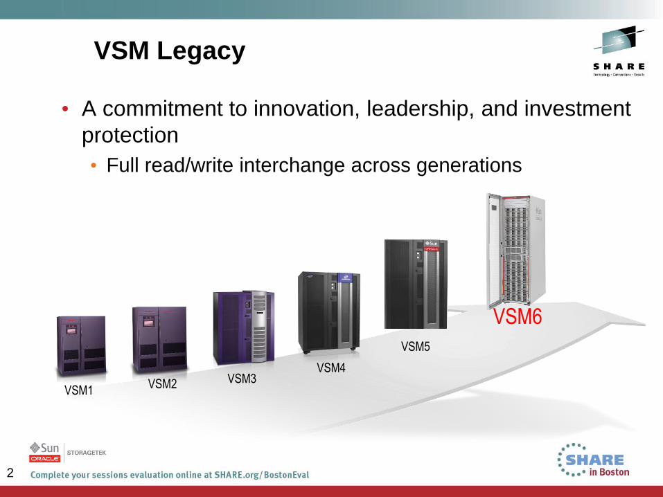
VSM Legacy
• A commitment to innovation, leadership, and investment
protection
• Full read/write interchange across generations
Entry
VSM6 VSM5
VSM1 VSM2 VSM3
VSM4
VSM5
3
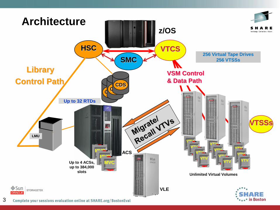
Architecture
HSC
Library
Control Path
VTCS
VTV
VTV
VTV
LMU
Up to 4 ACSs,
up to 384,000
slots Unlimited Virtual Volumes
256 Virtual Tape Drives
256 VTSSs
VSM Control
& Data Path
VTV
VTV
VTSSs
CDS CDS
CDS
Up to 32 RTDs
VTV
VTV
VTV
VTV VTV
VTV
ACS MVC
MVC
MVC
z/OS
SMC
VLE
4
4
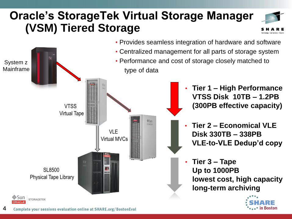
Oracle’s StorageTek Virtual Storage Manager (VSM) Tiered Storage
• Provides seamless integration of hardware and software
• Centralized management for all parts of storage system
• Performance and cost of storage closely matched to
type of data
• Tier 1 – High Performance
VTSS Disk 10TB – 1.2PB
(300PB effective capacity)
• Tier 2 – Economical VLE
Disk 330TB – 338PB
VLE-to-VLE Dedup’d copy
• Tier 3 – Tape
Up to 1000PB
lowest cost, high capacity
long-term archiving
System z
Mainframe
VTSS
Virtual Tape
VLE
Virtual MVCs
SL8500
Physical Tape Library
5
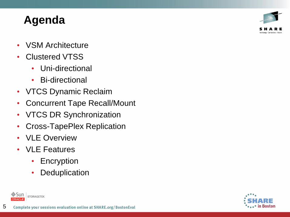
Agenda
• VSM Architecture
• Clustered VTSS
• Uni-directional
• Bi-directional
• VTCS Dynamic Reclaim
• Concurrent Tape Recall/Mount
• VTCS DR Synchronization
• Cross-TapePlex Replication
• VLE Overview
• VLE Features
• Encryption
• Deduplication
6
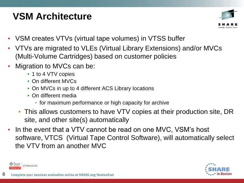
• VSM creates VTVs (virtual tape volumes) in VTSS buffer
• VTVs are migrated to VLEs (Virtual Library Extensions) and/or MVCs
(Multi-Volume Cartridges) based on customer policies
• Migration to MVCs can be: • 1 to 4 VTV copies
• On different MVCs
• On MVCs in up to 4 different ACS Library locations
• On different media
• for maximum performance or high capacity for archive
• This allows customers to have VTV copies at their production site, DR
site, and other site(s) automatically
• In the event that a VTV cannot be read on one MVC, VSM’s host
software, VTCS (Virtual Tape Control Software), will automatically select
the VTV from an another MVC
VSM Architecture
7
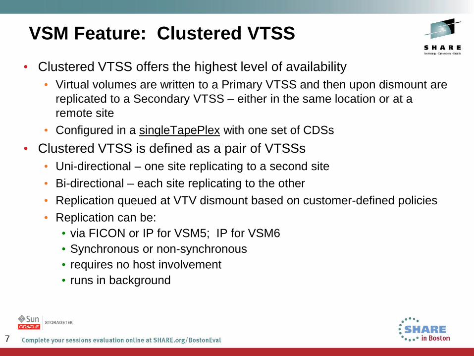
VSM Feature: Clustered VTSS
• Clustered VTSS offers the highest level of availability
• Virtual volumes are written to a Primary VTSS and then upon dismount are
replicated to a Secondary VTSS – either in the same location or at a
remote site
• Configured in a singleTapePlex with one set of CDSs
• Clustered VTSS is defined as a pair of VTSSs
• Uni-directional – one site replicating to a second site
• Bi-directional – each site replicating to the other
• Replication queued at VTV dismount based on customer-defined policies
• Replication can be:
• via FICON or IP for VSM5; IP for VSM6
• Synchronous or non-synchronous
• requires no host involvement
• runs in background
8
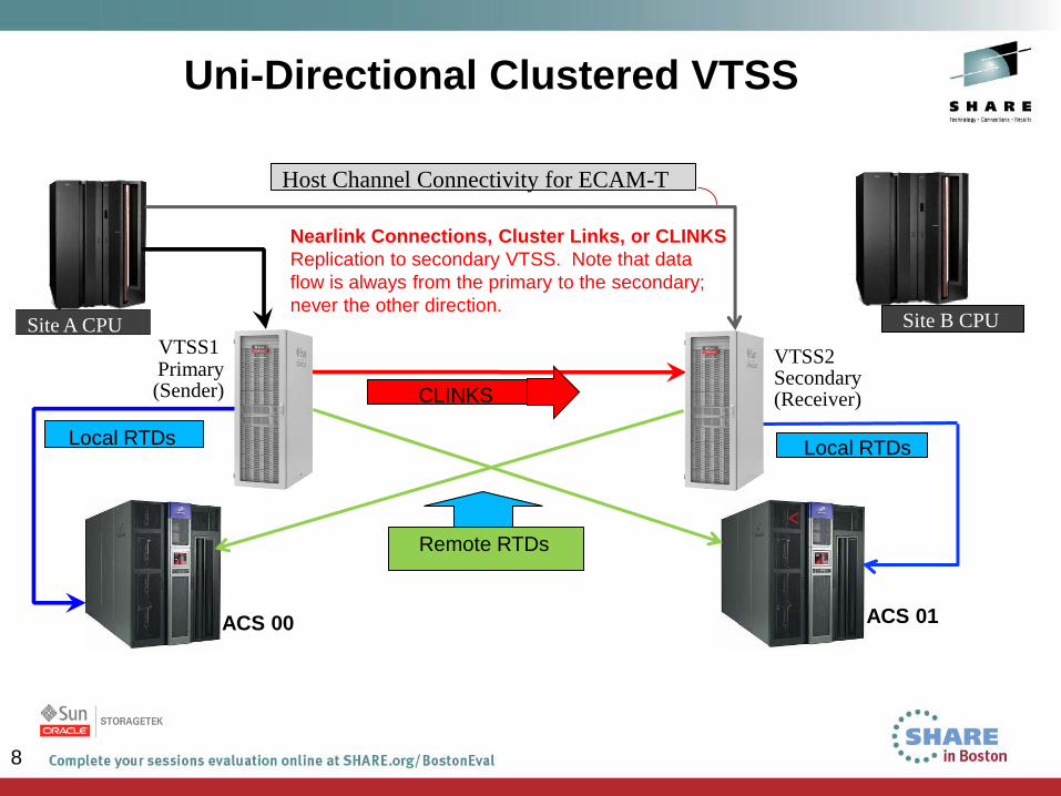
Uni-Directional Clustered VTSS
Nearlink Connections, Cluster Links, or CLINKS
Replication to secondary VTSS. Note that data
flow is always from the primary to the secondary;
never the other direction.
ACS 00 ACS 01
Local RTDs Local RTDs
Remote RTDs
CLINKS
Site A CPU Site B CPU
VTSS1 Primary (Sender)
VTSS2 Secondary (Receiver)
Host Channel Connectivity for ECAM-T
9
9
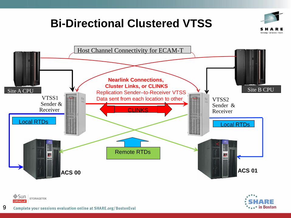
Bi-Directional Clustered VTSS
Nearlink Connections,
Cluster Links, or CLINKS
Replication Sender–to-Receiver VTSS
Data sent from each location to other
ACS 00 ACS 01
Local RTDs Local RTDs
Remote RTDs
CLINKS
Site A CPU Site B CPU
VTSS1 Sender & Receiver
VTSS2 Sender & Receiver
Host Channel Connectivity for ECAM-T
10
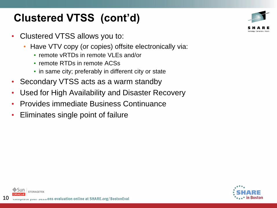
Clustered VTSS (cont’d)
• Clustered VTSS allows you to:
• Have VTV copy (or copies) offsite electronically via:
• remote vRTDs in remote VLEs and/or
• remote RTDs in remote ACSs
• in same city; preferably in different city or state
• Secondary VTSS acts as a warm standby
• Used for High Availability and Disaster Recovery
• Provides immediate Business Continuance
• Eliminates single point of failure
10
11
VSM Feature: VTCS Dynamic Reclaim
• With the introduction of higher-capacity tape drives, MVCs (Multi-
Volume Cartridges) now hold thousands of gigabytes of data, which are
individual datasets, or VTVs (Virtual Tape Volumes) stacked on the
tape, often with different expiration dates
• Capacity of Oracle’s StorageTek T10000x Tape Drives
• T10000B has a native capacity of 1 terabyte
• T10000C has a native capacity of 5 terabytes
• T10000D has a native capacity of 8.5 terabytes
• Over time, tapes becomes fragmented with non-current data caused by
expiring VTVs interspersed throughout the tape
• How can unused space be reclaimed fast and efficiently?
• Traditional reclaim is done when a fragmented MVC reaches a
customer-defined threshold, it requires the user to run a Reclaim job,
which recalls VTVs back into the VTCS buffer, and re-migrates them
back out to a different MVC
12
• Oracle’s StorageTek T10000B and T10000C tape drives introduced a
new tape technology called tape partitioning
• This provided an opportunity to dynamically reclaim unused space on
tapes
• VTCS Dynamic Reclaim is VSM’s implementation of reclamation for
partitioned MVCs
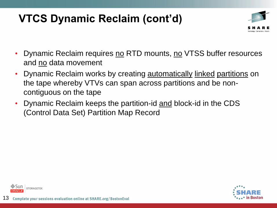
VTCS Dynamic Reclaim (cont’d)
13
• Dynamic Reclaim requires no RTD mounts, no VTSS buffer resources
and no data movement
• Dynamic Reclaim works by creating automatically linked partitions on
the tape whereby VTVs can span across partitions and be non-
contiguous on the tape
• Dynamic Reclaim keeps the partition-id and block-id in the CDS
(Control Data Set) Partition Map Record
VTCS Dynamic Reclaim (cont’d)
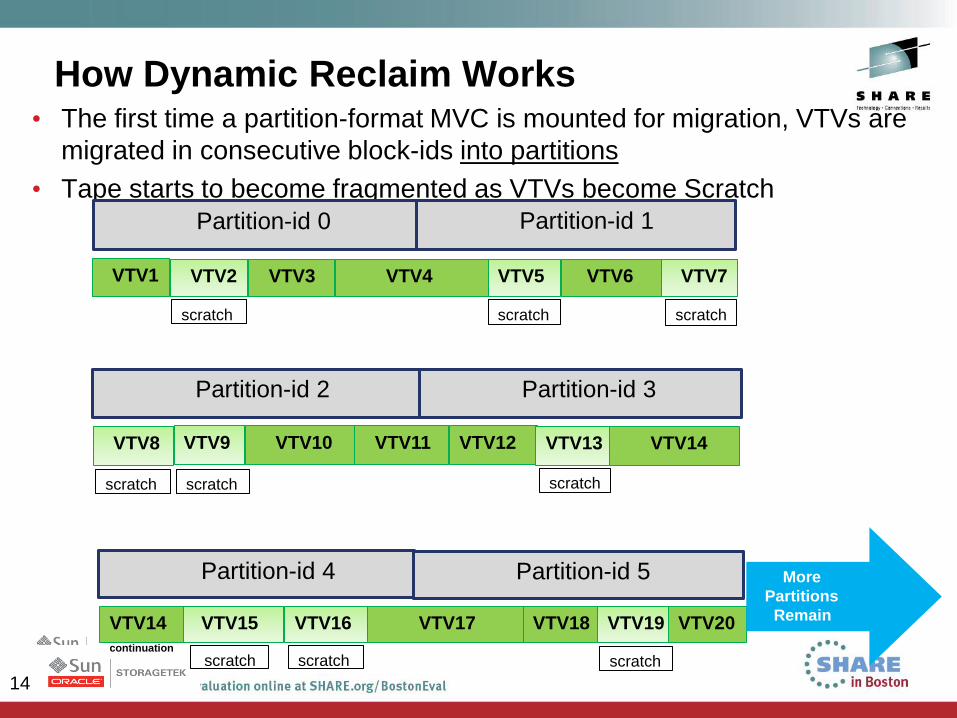
14
How Dynamic Reclaim Works • The first time a partition-format MVC is mounted for migration, VTVs are
migrated in consecutive block-ids into partitions
• Tape starts to become fragmented as VTVs become Scratch
Partition-id 2
VTV9 VTV10 VTV11
Partition-id 3
VTV12 VTV13 VTV14 VTV8
Partition-id 0
VTV2 VTV3 VTV4
Partition-id 1
VTV5 VTV6 VTV1 VTV7
Partition-id 4
VTV15 VTV16 VTV17
Partition-id 5
VTV18 VTV19 VTV14
continuation
VTV20
More
Partitions
Remain
scratch
scratch scratch scratch
scratch scratch scratch
scratch scratch
15
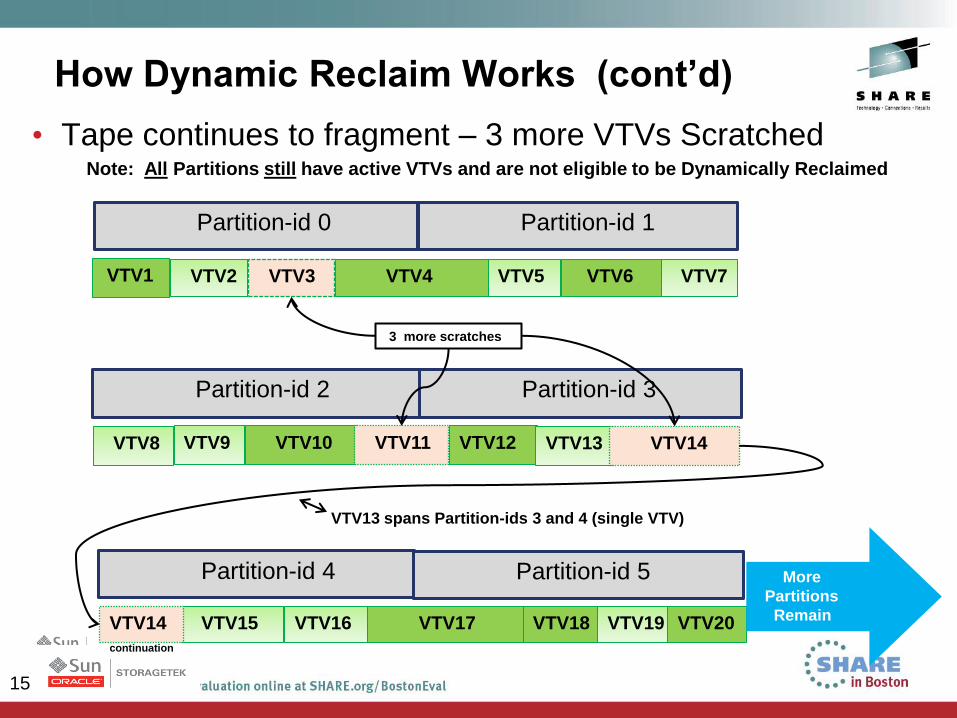
How Dynamic Reclaim Works (cont’d)
• Tape continues to fragment – 3 more VTVs Scratched Note: All Partitions still have active VTVs and are not eligible to be Dynamically Reclaimed
Partition-id 2
VTV9 VTV10 VTV11
Partition-id 3
VTV12 VTV13 VTV14 VTV8
Partition-id 0
VTV2 VTV3 VTV4
Partition-id 1
VTV5 VTV6 VTV1 VTV7
Partition-id 4
VTV15 VTV16 VTV17
Partition-id 5
VTV18 VTV19 VTV14
continuation
VTV20
More
Partitions
Remain
VTV13 spans Partition-ids 3 and 4 (single VTV)
3 more scratches
16
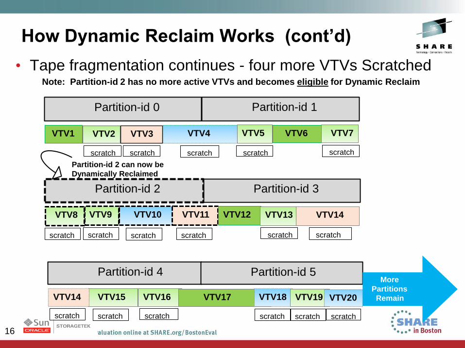
How Dynamic Reclaim Works (cont’d)
• Tape fragmentation continues - four more VTVs Scratched Note: Partition-id 2 has no more active VTVs and becomes eligible for Dynamic Reclaim
Partition-id 2
VTV9 VTV10 VTV11
Partition-id 3
VTV12 VTV13 VTV14 VTV8
Partition-id 0
VTV2 VTV3 VTV4
Partition-id 1
VTV5 VTV6 VTV1 VTV7
Partition-id 4
VTV15 VTV16 VTV17
Partition-id 5
VTV18 VTV19 VTV14 VTV20
More
Partitions
Remain
Partition-id 2 can now be
Dynamically Reclaimed
scratch scratch scratch scratch
scratch
scratch
scratch scratch
scratch scratch scratch scratch
scratch
scratch scratch scratch scratch
17
Dynamic Reclaim Executes
• So now we have an MVC that has been filled with VTVs
• The tape has become fragmented
• Once the tape becomes fragmented over and above the customer-
defined threshold for Dynamic Reclaim, VTCS Dynamic Reclaim runs
automatically
• During dynamic reclamation, each partition is examined to see if there
are any active VTVs
• Only partitions with no active VTVs will be reclaimed during this
execution process
18
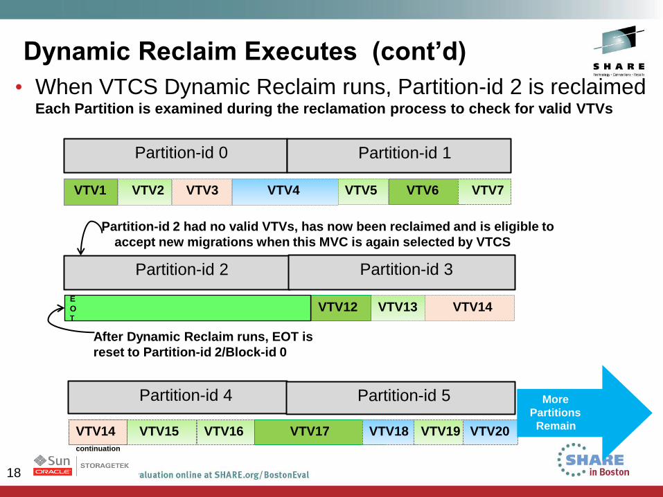
Dynamic Reclaim Executes (cont’d)
• When VTCS Dynamic Reclaim runs, Partition-id 2 is reclaimed Each Partition is examined during the reclamation process to check for valid VTVs
Partition-id 2 Partition-id 3
VTV12 VTV13 VTV14
VTV2 VTV3 VTV4 VTV5 VTV6 VTV1 VTV7
Partition-id 4
VTV15 VTV16 VTV17
Partition-id 5
VTV18 VTV19 VTV14
continuation
VTV20
More
Partitions
Remain
Partition-id 2 had no valid VTVs, has now been reclaimed and is eligible to
accept new migrations when this MVC is again selected by VTCS
After Dynamic Reclaim runs, EOT is
reset to Partition-id 2/Block-id 0
E
OT
Partition-id 0 Partition-id 1
19
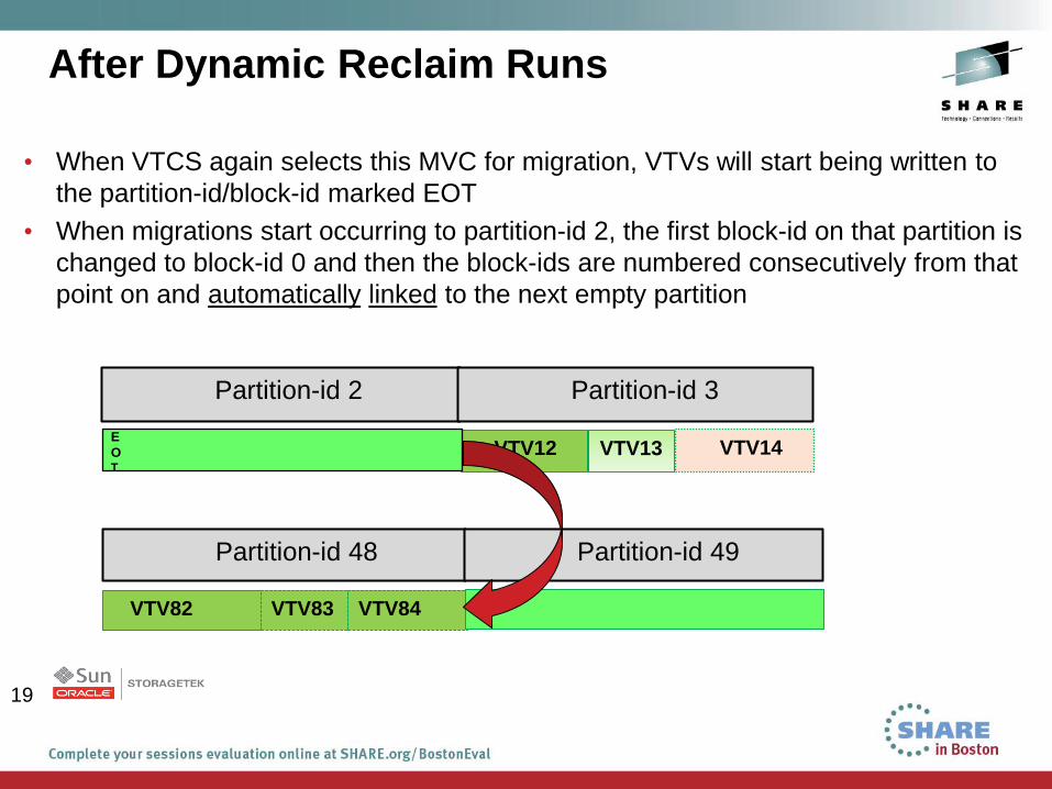
After Dynamic Reclaim Runs
• When VTCS again selects this MVC for migration, VTVs will start being written to
the partition-id/block-id marked EOT
• When migrations start occurring to partition-id 2, the first block-id on that partition is
changed to block-id 0 and then the block-ids are numbered consecutively from that
point on and automatically linked to the next empty partition
Partition-id 2 Partition-id 3
VTV12 VTV13 VTV14
VTV82
Partition-id 48
VTV83 VTV84
Partition-id 49
E
OT
20
Dynamic Reclaim Enablement
• The first time an MVC cartridge is used, the format, standard or partitioned,
is determined by whether Dynamic Reclaim is enabled
• Dynamic Reclaim is enabled by defining the VTCS CONFIG INPLACE
parameter, which is a new parameter on the VTCS CONFIg RECLAIM
Statement The settings for this parameter are:
• INPLACE(YES) – this specifies that Dynamic Reclaim is enabled at the
global level for all Storage Classes and that the fragmentation
percentage to start Dynamic Reclaim (INPTHRSH) will also be specified
globally
• INPLACE(NO) – this specifies that Dynamic Reclaim is enabled, but the
parameter will be specified for certain Storage Classes on each
STORclas statement
21
VSM Feature: Concurrent Tape Recall/Mount
• The problem:
• Recalls of VTVs from tape has always meant that the entire VTV had to
be recalled back into the buffer from the tape before the application could
begin to access the data.
• The time to recall the VTV is determined by:
• the time to mount the MVC on the drive
• the time to locate the VTV on the tape
• the recall data transfer rate times the size of the VTV
• Depending on the size of the VTV, the VTSS FICON recall data transfer
rate can be the dominant portion of the overall recall time. Because of
this, many customers will intentionally use smaller VTV sizes, 400 MB vs.
4GB. This reduces the recall time, but significantly increases the number
of VTVs that the customer, MVS, and VTCS have to manage.
22
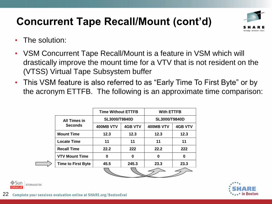
Concurrent Tape Recall/Mount (cont’d)
• The solution:
• VSM Concurrent Tape Recall/Mount is a feature in VSM which will
drastically improve the mount time for a VTV that is not resident on the
(VTSS) Virtual Tape Subsystem buffer
• This VSM feature is also referred to as “Early Time To First Byte” or by
the acronym ETTFB. The following is an approximate time comparison:
Time Without ETTFB With ETTFB
All Times in Seconds
SL3000/T9840D SL3000/T9840D
400MB VTV 4GB VTV 400MB VTV 4GB VTV
Mount Time 12.3 12.3 12.3 12.3
Locate Time 11 11 11 11
Recall Time 22.2 222 22.2 222
VTV Mount Time 0 0 0 0
Time to First Byte 45.5 245.3 23.3 23.3
23
How Does ETTFB Work?
• The concept of the ETTFB feature is to reduce the time to first byte as
seen by the application job.
• This is achieved by overlapping the VTV recall and mount.
• Instead of waiting for the entire recall to complete, after the recall has
been initiated, the VTV is concurrently mounted on the VTD as well.
• This allows the application to access the VTV while it is still being
recalled.
• VTSS is responsible for pacing the VTD during the recall process. If
the application attempts to read part of the VTV that has not yet been
recalled, the application’s I/O request will be blocked until the required
VTV data has been recalled.
24
How to Enable ETTFB
• Two new VTCS CONFIG parameters are being provided:
• A new VTCS CONFIG GLOBAL statement parameter
FASTRECL=YES/NO will enable or disable the ETTFB feature for
all VTSSs in the configuration.
• Note: This feature is Disabled by default.
• A new VTCS CONFIG VTSS statement parameter NOERLYMT will
allow the customer to disable the ETTFB feature for an individual
VTSS. This parameter is only relevant if the FASTRECL=YES is
globally specified.
25
VSM Feature: VTCS DR Synchronization
• How to ensure critical VTV data is synchronized with CDS metadata:
• Ensure all Disaster Recovery critical data has been migrated and is
secured at the customer’s recovery location
• Establish system checkpoints in order to establish a recovery point
• Ensure that DR data remains consistent with metadata until the next
checkpoint
• The metadata copy must be valid and complete when a disaster is
declared, either real or test
• Allow the VSM customer to create CDS backups that reflect
checkpoints of the VSM environment with a consistent set of DR data
at a given point in time
• The CDS backup, plus other backups (e.g. Tape Management
Catalog, System Catalogs) then form a checkpoint of the entire
system
• VTCS DR Synchronization is a feature that can provide all of these
26
• Once the customer has determined which data is DR critical:
• The DRMONitr Utility is run against the data. This will stall a job stream
until the VTV copies have reached their MVC target destination(s).
• Then the DRCHKPT Utility is run, which establishes a checkpoint time.
This serves to protect MVC content until some point in the future (i.e.
the next DRCHKPT run).
• After DRMONitr and DRCHKPT have completed, then the CDS backup
should be taken, along with other DR critical datasets, such as the TMC
and MVS Catalogs.
• Meanwhile, don’t allow overwrites on MVCs until the next DR baseline
is established – this is protected by the utility software
• In the event a disaster is declared (real or test), the CDS is restored from
the current backup. Because the backup’s MVC contents are protected,
they can be used without the need for audits because they will be
synchronized with the CDS.
VTCS DR Synchronization (cont’d)
27
VSM Feature: Cross-TapePlex Replication (CTR)
• Cross-TapePlex Replication operates as an electronic Export and
electronic Import of VTV data into a separate TapePlex, with its own
CDS configuration, via FICON or IP CLINKs for VSM5, or IP CLINKs for
VSM6
• Metadata is transmitted from sending to receiving TapePlex over IP
using SMC HTTP
• Originating TapePlex retains ownership of the VTV
• Receiving TapePlex cannot update or scratch VTV
• When VTV is scratched at originating TapePlex, all copies will be
scratched
• Provides additional data copies for cascading unlimited number of data
copies within TapePlexes and across TapePlexes by the receiving
TapePlex’s migration policies
28
Cross-TapePlex Replication (CTR) (cont’d)
• DR tests can be run without impacting or disrupting the production
environment
• If a VTV is needed to be sent back to the owning TapePlex, the
electronic export automatically recalls the VTV back to the originating
TapePlex
• The EEXPORT Utility can also be used to bring the VTV back to the
originating TapePlex manually
• CTR Requirements:
• VTV ranges for the replicated VTVs in both TapePlexes must be the same
• No overlapping volsers allowed
• Management Class names for the replicated VTVs must be identical in both
TapePlexes
29
29
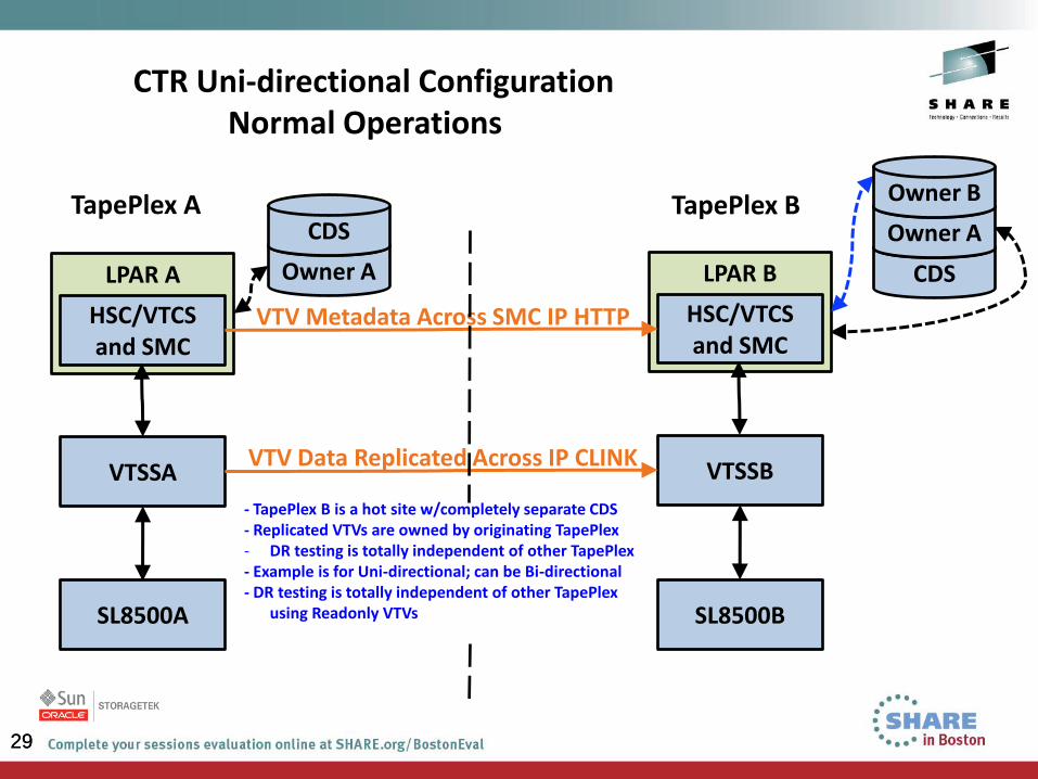
CTR Uni-directional Configuration Normal Operations
Owner A
CDS
VTSSA
SL8500A
LPAR A
HSC/VTCS and SMC
VTSSB
SL8500B
LPAR B
HSC/VTCS and SMC
TapePlex A
VTV Metadata Across SMC IP HTTP
VTV Data Replicated Across IP CLINK
TapePlex B
- TapePlex B is a hot site w/completely separate CDS - Replicated VTVs are owned by originating TapePlex - DR testing is totally independent of other TapePlex - Example is for Uni-directional; can be Bi-directional - DR testing is totally independent of other TapePlex
using Readonly VTVs
CDS
Owner A
Owner B
30
30
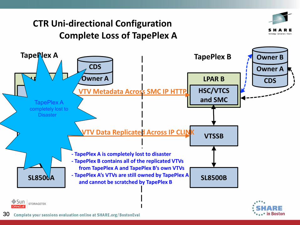
CTR Uni-directional Configuration Complete Loss of TapePlex A
Owner A
CDS
VTSSA
SL8500A
LPAR A
HSC/VTCS and SMC
VTSSB
SL8500B
LPAR B
HSC/VTCS and SMC
TapePlex A
VTV Metadata Across SMC IP HTTP
VTV Data Replicated Across IP CLINK
TapePlex B
- TapePlex A is completely lost to disaster - TapePlex B contains all of the replicated VTVs
from TapePlex A and TapePlex B’s own VTVs - TapePlex A’s VTVs are still owned by TapePlex A
and cannot be scratched by TapePlex B
CDS
Owner A
Owner B
31
31
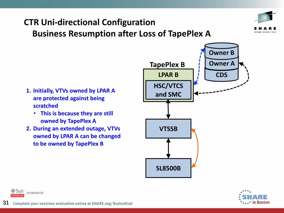
CTR Uni-directional Configuration Business Resumption after Loss of TapePlex A
VTSSB
SL8500B
LPAR B
HSC/VTCS and SMC
TapePlex B
1. Initially, VTVs owned by LPAR A are protected against being scratched • This is because they are still
owned by TapePlex A 2. During an extended outage, VTVs
owned by LPAR A can be changed to be owned by TapePlex B
CDS
Owner A
Owner B
32
Virtual Library Extension (VLE) Overview
• VLE is “more virtual tape” –
• VLE looks like a tape library to the VTSS and VTCS
• The VTVs are stored in Virtual MVCs (VMVCs) on disk
• At the VLE, reads and writes are at disk speed...more virtual tape
means no real tape mounts/dismounts
• VLE is a collection of nodes, which together comprise a VLE system,
and are interconnected with a private internal network – any node can
access any other node in the complex
• The VLE solution consists of VTSS, VLE appliance (hardware and
software), VTCS and SMC
• VLE, therefore, provides an additional storage tier in the VSM solution.
VTVs can now migrate from VTSS to VLE to provide fast access to
recent data. Additionally, VTVs can transition from VLE storage to real
tape media (MVCs) for long term archive
33
VLE Features
• Multi-Node VLE – This feature enables massive scaling of the VLE
storage system
• You can construct multi-node systems that can consist of one to 64 nodes,
with multiple nodes interconnected by a private network
• A multi-node VLE appears to SMC/VTCS as a single VLE
• VLE-to-VLE Copy - The VLE storage system can now manage data
transfers independent of the VTSS
• If you want to migrate two VTV copies to separate, interconnected VLEs, for
example, you can use Management and Storage Classes to migrate one
copy using VTSS-to-VLE connections and the second copy using VLE-to-
VLE connections. The second migration , therefore, uses no VTSS
resources
• This frees VTSS resources for other work while the additional VTV copies are
being made, which improves the overall VTSS throughput
34
• Encryption – This enables encryption of VMVCs written to the VLE
• Feature is enabled via an encryption key stored on the node, on a per node
basis, backed up on a USB device
• Technology which protects information by converting it into unreadable code
• No additional charge for Encryption
• Encryption takes place in the VLE
• Enabled via VLE GUI
• Data Deduplication - This eliminates redundant data in a VLE system
• Replaces redundant pieces of data with a reference to the original instance
• Is controlled by a STORCLAS statement parameter
• Increases the effective capacity of the VLE
• Is performed by the VLE before the VTV is written to a VMVC
VLE Features (cont’d)
35
VLE Features (cont’d)
More on Data Deduplication:
• If Dedup is enabled, as data is migrated into the VLE from the VTSS, each 4K
block is analyzed, using hashing algorithms and table lookups, to determine if
it is unique or if another copy already exists within the VLE
• When a block of data already exists on another VMVC, then the VTV data will
point to shared data on the other VMVC
• When VTVs are migrated with Deduplication enabled to a VMVC in the VLE,
they are broken up into VTV data and shared data
• Dedup requires a reconstruction process to rehydrate the data for a recall
back to VTSS
• Included with base VLE code at no charge.
36
VLE Features (cont’d)
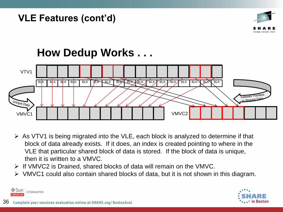
How Dedup Works . . .
BLK
As VTV1 is being migrated into the VLE, each block is analyzed to determine if that
block of data already exists. If it does, an index is created pointing to where in the
VLE that particular shared block of data is stored. If the block of data is unique,
then it is written to a VMVC.
If VMVC2 is Drained, shared blocks of data will remain on the VMVC.
VMVC1 could also contain shared blocks of data, but it is not shown in this diagram.
VTV1
BLK BLK BLK BLK BLK BLK BLK BLK BLK BLK BLK BLK BLK BLK BLK BLK
VMVC1
VMVC2
37
Thank you . . .
Questions ?