features, installation, design principles - davis · pdf filefeatures, installation, design...
TRANSCRIPT
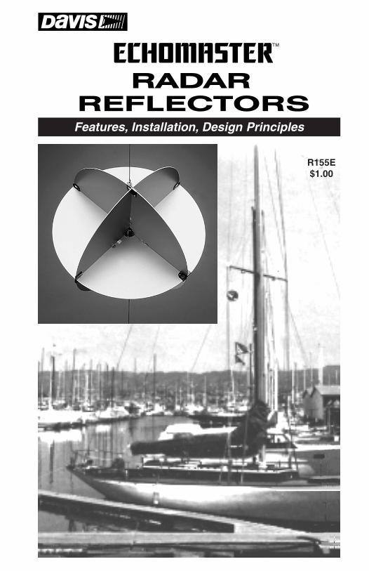
Features, Installation, Design Principles
R155E$1.00
Echomaster User’s Manual00155.010, Rev. G
January 2009
Total pages 16
Trim to 5.5 x 8.5"
Black ink only
Page 1 (front cover)
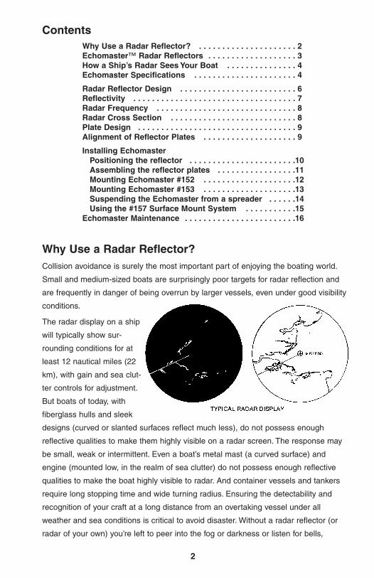
Why Use a Radar Reflector?Collision avoidance is surely the most important part of enjoying the boating world.
Small and medium-sized boats are surprisingly poor targets for radar reflection and
are frequently in danger of being overrun by larger vessels, even under good visibility
conditions.
The radar display on a ship
will typically show sur-
rounding conditions for at
least 12 nautical miles (22
km), with gain and sea clut-
ter controls for adjustment.
But boats of today, with
fiberglass hulls and sleek
designs (curved or slanted surfaces reflect much less), do not possess enough
reflective qualities to make them highly visible on a radar screen. The response may
be small, weak or intermittent. Even a boat’s metal mast (a curved surface) and
engine (mounted low, in the realm of sea clutter) do not possess enough reflective
qualities to make the boat highly visible to radar. And container vessels and tankers
require long stopping time and wide turning radius. Ensuring the detectability and
recognition of your craft at a long distance from an overtaking vessel under all
weather and sea conditions is critical to avoid disaster. Without a radar reflector (or
radar of your own) you’re left to peer into the fog or darkness or listen for bells,
2
Why Use a Radar Reflector? . . . . . . . . . . . . . . . . . . . . . 2Echomaster™ Radar Reflectors . . . . . . . . . . . . . . . . . . . 3How a Ship’s Radar Sees Your Boat . . . . . . . . . . . . . . . 4Echomaster Specifications . . . . . . . . . . . . . . . . . . . . . . 4
Radar Reflector Design . . . . . . . . . . . . . . . . . . . . . . . . . 6Reflectivity . . . . . . . . . . . . . . . . . . . . . . . . . . . . . . . . . . . 7Radar Frequency . . . . . . . . . . . . . . . . . . . . . . . . . . . . . . 8Radar Cross Section . . . . . . . . . . . . . . . . . . . . . . . . . . . 8Plate Design . . . . . . . . . . . . . . . . . . . . . . . . . . . . . . . . . . 9Alignment of Reflector Plates . . . . . . . . . . . . . . . . . . . . 9
Installing Echomaster Positioning the reflector . . . . . . . . . . . . . . . . . . . . . . .10Assembling the reflector plates . . . . . . . . . . . . . . . . .11Mounting Echomaster #152 . . . . . . . . . . . . . . . . . . . .12Mounting Echomaster #153 . . . . . . . . . . . . . . . . . . . .13Suspending the Echomaster from a spreader . . . . . .14Using the #157 Surface Mount System . . . . . . . . . . .15
Echomaster Maintenance . . . . . . . . . . . . . . . . . . . . . . . .16
Contents
3
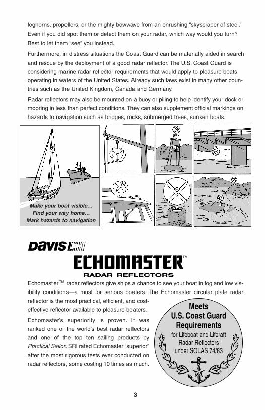
Echomaster™ radar reflectors give ships a chance to see your boat in fog and low vis-
ibility conditions—a must for serious boaters. The Echomaster circular plate radar
reflector is the most practical, efficient, and cost-
effective reflector available to pleasure boaters.
Echomaster’s superiority is proven. It was
ranked one of the world’s best radar reflectors
and one of the top ten sailing products by
Practical Sailor. SRI rated Echomaster “superior”
after the most rigorous tests ever conducted on
radar reflectors, some costing 10 times as much.
Make your boat visible…Find your way home…
Mark hazards to navigation
foghorns, propellers, or the mighty bowwave from an onrushing “skyscraper of steel.”
Even if you did spot them or detect them on your radar, which way would you turn?
Best to let them “see” you instead.
Furtherrnore, in distress situations the Coast Guard can be materially aided in search
and rescue by the deployment of a good radar reflector. The U.S. Coast Guard is
considering marine radar reflector requirements that would apply to pleasure boats
operating in waters of the United States. Already such laws exist in many other coun-
tries such as the United Kingdom, Canada and Germany.
Radar reflectors may also be mounted on a buoy or piling to help identify your dock or
mooring in less than perfect conditions. They can also supplement official markings on
hazards to navigation such as bridges, rocks, submerged trees, sunken boats.
Echomaster SpecificationsReflector plates are 12.5" (32 cm) diameter,
circular, aluminum. Plates provide 13.2
square yards (12 sq. meters) of maximum
effective radar cross section in the X or 3 cm
band (9–9.6 GHz frequency), based on opti-
mum orientation between the reflector and
radar. Echomaster offers equivalent radar
cross section of conventional triangular plate
reflector with approximate 17" (43 cm) diago-
nal dimension.
Plates are made of robust 0.05" (1.3 mm) marine grade aluminum; sufficient thick-
ness to minimize flexing. Dimples in plates allow corner latches to attach precisely,
minimizing angular distortion.
Windage holes reduce aerodynamic drag and allow assembly of the reflector around
a backstay. Windage hole size 1.25" (32 mm).
DAVISECHOMASTER
#152, 153
DAVIS EMERGENCY
RADARREFLECTOR
#151
MOBRI RADARREFLECTOR
FIRDELL BLIPPER
RADAR FLAG
Admiralty surface weapons test, England
4
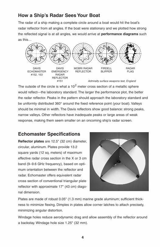
How a Ship’s Radar Sees Your BoatThe radar of a ship making a complete circle around a boat would hit the boat’s
radar reflector from all angles. If the boat were stationary and we plotted how strong
the reflected signal is at all angles, we would arrive at performance diagrams such
as this…
The outside of the circle is what a 102 meter cross section of a metallic sphere
would reflect—the laboratory standard. The larger the performance plot, the better
the radar reflector. Peaks in the pattern should approach the laboratory standard and
be uniformly distributed 360° around the fixed reference point (your boat). Valleys
should be minimal in width. The Davis reflectors show good balance: strong peaks,
narrow valleys. Other reflectors have inadequate peaks or large areas of weak
response, making them seem smaller on an oncoming ship’s radar screen.
5
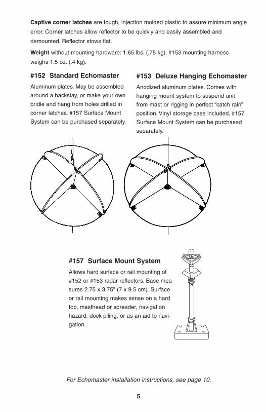
For Echomaster installation instructions, see page 10.
#157 Surface Mount System
Allows hard surface or rail mounting of
#152 or #153 radar reflectors. Base mea-
sures 2.75 x 3.75" (7 x 9.5 cm). Surface
or rail mounting makes sense on a hard
top, masthead or spreader, navigation
hazard, dock piling, or as an aid to navi-
gation.
#152 Standard Echomaster
Aluminum plates. May be assembled
around a backstay, or make your own
bridle and hang from holes drilled in
corner latches. #157 Surface Mount
System can be purchased separately.
#153 Deluxe Hanging Echomaster
Anodized aluminum plates. Comes with
hanging mount system to suspend unit
from mast or rigging in perfect “catch rain”
position. Vinyl storage case included. #157
Surface Mount System can be purchased
separately.
Captive corner latches are tough, injection molded plastic to assure minimum angle
error. Corner latches allow reflector to be quickly and easily assembled and
demounted. Reflector stows flat.
Weight without mounting hardware: 1.65 lbs. (.75 kg). #153 mounting harness
weighs 1.5 oz. (.4 kg).
6
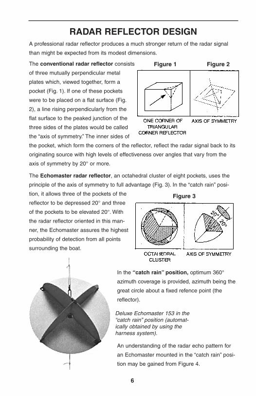
RADAR REFLECTOR DESIGNA professional radar reflector produces a much stronger return of the radar signal
than might be expected from its modest dimensions.
The conventional radar reflector consists
of three mutually perpendicular metal
plates which, viewed together, form a
pocket (Fig. 1). If one of these pockets
were to be placed on a flat surface (Fig.
2), a line rising perpendicularly from the
flat surface to the peaked junction of the
three sides of the plates would be called
the “axis of symmetry.” The inner sides of
the pocket, which form the corners of the reflector, reflect the radar signal back to its
originating source with high levels of effectiveness over angles that vary from the
axis of symmetry by 20° or more.
Figure 1 Figure 2
The Echomaster radar reflector, an octahedral cluster of eight pockets, uses the
principle of the axis of symmetry to full advantage (Fig. 3). In the “catch rain” posi-
tion, it allows three of the pockets of the
reflector to be depressed 20° and three
of the pockets to be elevated 20°. With
the radar reflector oriented in this man-
ner, the Echomaster assures the highest
probability of detection from all points
surrounding the boat.
Figure 3
Deluxe Echomaster 153 in the“catch rain” position (automat-ically obtained by using theharness system).
In the “catch rain” position, optimum 360°
azimuth coverage is provided, azimuth being the
great circle about a fixed refence point (the
reflector).
An understanding of the radar echo pattern for
an Echomaster mounted in the “catch rain” posi-
tion may be gained from Figure 4.
7
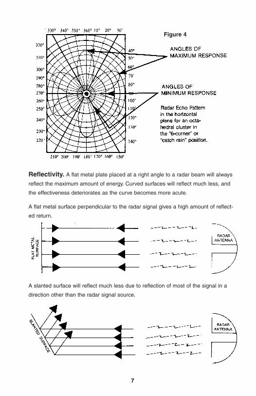
Figure 4
Reflectivity. A flat metal plate placed at a right angle to a radar beam will always
reflect the maximum amount of energy. Curved surfaces will reflect much less, and
the effectiveness deteriorates as the curve becomes more acute.
A slanted surface will reflect much less due to reflection of most of the signal in a
direction other than the radar signal source.
A flat metal surface perpendicular to the radar signal gives a high amount of reflect-
ed return.
Radar frequency. The frequency of the radar in use has a marked effect on the
amount of signal that is returned from a given sized reflector. Higher frequency or
shorter wavelength radars produce much brighter returns. Fortunately, the majority of
marine radars operate in the relatively high frequency X or 3 cm band.
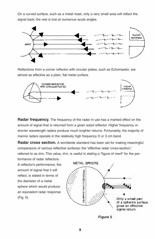
Radar cross section. A worldwide standard has been set for making meaningful
comparisons of various reflective surfaces: the “effective radar cross-section,”
referred to as σm. This value, σm, is useful in stating a “figure of merit” for the per-
formance of radar reflectors.
A reflector’s performance, the
amount of signal that it will
reflect, is stated in terms of
the diameter of a metal
sphere which would produce
an equivalent radar response
(Fig. 5).
8
Figure 5
On a curved surface, such as a metal mast, only a very small area will reflect the
signal back; the rest is lost at numerous acute angles.
Reflections from a corner reflector with circular plates, such as Echomaster, are
almost as effective as a plain, flat metal surface.
9
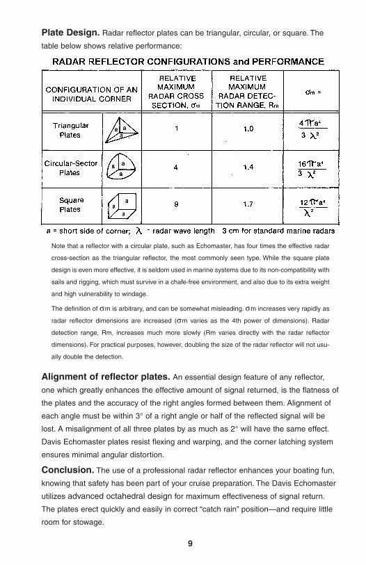
Plate Design. Radar reflector plates can be triangular, circular, or square. The
table below shows relative performance:
Note that a reflector with a circular plate, such as Echomaster, has four times the effective radar
cross-section as the triangular reflector, the most commonly seen type. While the square plate
design is even more effective, it is seldom used in marine systems due to its non-compatibility with
sails and rigging, which must survive in a chafe-free environment, and also due to its extra weight
and high vulnerability to windage.
The definition of σm is arbitrary, and can be somewhat misleading. σm increases very rapidly as
radar reflector dimensions are increased (σm varies as the 4th power of dimensions). Radar
detection range, Rm, increases much more slowly (Rm varies directly with the radar reflector
dimensions). For practical purposes, however, doubling the size of the radar reflector will not usu-
ally double the detection.
Alignment of reflector plates. An essential design feature of any reflector,
one which greatly enhances the effective amount of signal returned, is the flatness of
the plates and the accuracy of the right angles formed between them. Alignment of
each angle must be within 3° of a right angle or half of the reflected signal will be
lost. A misalignment of all three plates by as much as 2° will have the same effect.
Davis Echomaster plates resist flexing and warping, and the corner latching system
ensures minimal angular distortion.
Conclusion. The use of a professional radar reflector enhances your boating fun,
knowing that safety has been part of your cruise preparation. The Davis Echomaster
utilizes advanced octahedral design for maximum effectiveness of signal return.
The plates erect quickly and easily in correct “catch rain” position—and require little
room for stowage.
10
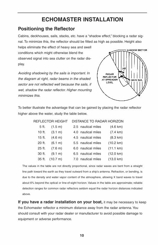
To better illustrate the advantage that can be gained by placing the radar reflector
higher above the water, study the table below.
REFLECTOR HEIGHT DISTANCE TO RADAR HORIZON
5 ft. (1.5 m) 2.5 nautical miles (4.6 km)
10 ft. (3.1 m) 4.0 nautical miles (7.4 km)
15 ft. (4.6 m) 4.5 nautical miles (8.3 km)
20 ft. (6.1 m) 5.5 nautical miles (10.2 km)
25 ft. (7.6 m) 6.0 nautical miles (11.1 km)
30 ft. (9.1 m) 6.5 nautical miles (12.0 km)
35 ft. (10.7 m) 7.0 nautical miles (13.0 km)
The values in the table are not directly proportional, since radar waves are bent from a straight
line path toward the earth as they travel outward from a ship’s antenna. Refraction, or bending, is
due to the density and water vapor content of the atmosphere, allowing X band waves to travel
about 6% beyond the optical or line-of-sight horizon. Values in the table are approximate; reliable
detection ranges for common radar reflectors seldom equal the radar horizon distances indicated
above.
If you have a radar installation on your boat, it may be necessary to keep
the Echomaster reflector a minimum distance away from the radar antenna. You
should consult with your radar dealer or manufacturer to avoid possible damage to
equipment or adverse performance.
Avoiding shadowing by the sails is important. In
the diagram at right, radar beams in the shaded
sector are not reflected well because the sails, if
wet, shadow the radar reflector. Higher mounting
minimizes this.
Positioning the ReflectorCabins, deckhouses, sails, stacks, etc. have a “shadow effect,” blocking a radar sig-
nal. To minimize this, the reflector should be fitted as high as possible. Height also
helps eliminate the effect of heavy sea and swell
conditions which might otherwise blend the
observed signal into sea clutter on the radar dis-
play.
ECHOMASTER INSTALLATION
11
Assembling the Reflector Plates
In the “catch rain” position, Echomaster's octahedral cluster orients all panels at 20°
to the axis of symmetry. At this angle, all the inner pockets have the unique property
of always reflecting a radar signal back to its originating source with high effective-
ness. At the same time, optimum 360° azimuth coverage is provided. In addition, the
pocket pointing straight up will aid in airborne search and rescue operations.
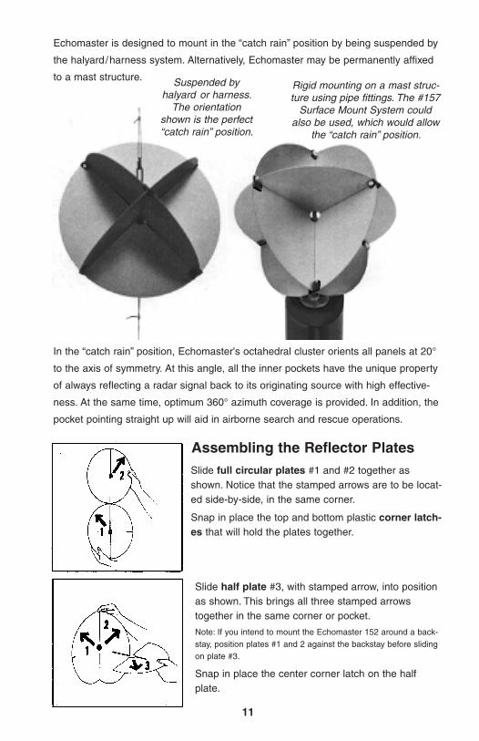
Echomaster is designed to mount in the “catch rain” position by being suspended by
the halyard/harness system. Alternatively, Echomaster may be permanently affixed
to a mast structure. Suspended byhalyard or harness.
The orientationshown is the perfect“catch rain” position.
Rigid mounting on a mast struc-ture using pipe fittings. The #157
Surface Mount System couldalso be used, which would allow
the “catch rain” position.
Slide full circular plates #1 and #2 together asshown. Notice that the stamped arrows are to be locat-ed side-by-side, in the same corner.
Snap in place the top and bottom plastic corner latch-es that will hold the plates together.
Slide half plate #3, with stamped arrow, into positionas shown. This brings all three stamped arrowstogether in the same corner or pocket.
Note: If you intend to mount the Echomaster 152 around a back-stay, position plates #1 and 2 against the backstay before slidingon plate #3.
Snap in place the center corner latch on the halfplate.
12
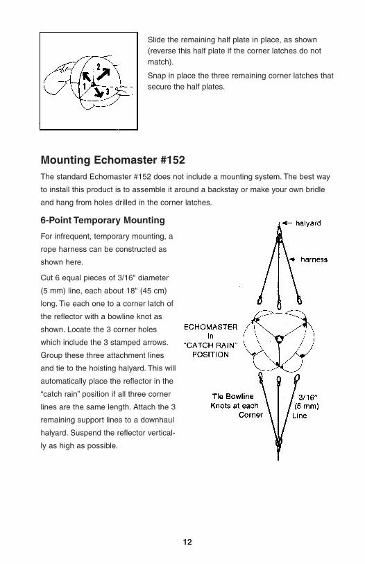
Cut 6 equal pieces of 3/16" diameter
(5 mm) line, each about 18" (45 cm)
long. Tie each one to a corner latch of
the reflector with a bowline knot as
shown. Locate the 3 corner holes
which include the 3 stamped arrows.
Group these three attachment lines
and tie to the hoisting halyard. This will
automatically place the reflector in the
“catch rain” position if all three corner
lines are the same length. Attach the 3
remaining support lines to a downhaul
halyard. Suspend the reflector vertical-
ly as high as possible.
Mounting Echomaster #152The standard Echomaster #152 does not include a mounting system. The best way
to install this product is to assemble it around a backstay or make your own bridle
and hang from holes drilled in the corner latches.
6-Point Temporary Mounting
For infrequent, temporary mounting, a
rope harness can be constructed as
shown here.
Slide the remaining half plate in place, as shown(reverse this half plate if the corner latches do notmatch).
Snap in place the three remaining corner latches thatsecure the half plates.
13
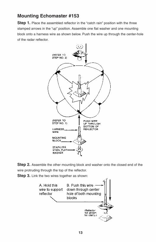
Mounting Echomaster #153Step 1. Place the assembled reflector in the “catch rain” position with the three
stamped arrows in the “up” position. Assemble one flat washer and one mounting
block onto a harness wire as shown below. Push the wire up through the center-hole
of the radar reflector.
Step 2. Assemble the other mounting block and washer onto the closed end of the
wire protruding through the top of the reflector.
Step 3. Link the two wires together as shown:
14
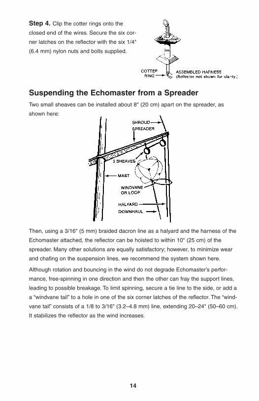
Step 4. Clip the cotter rings onto the
closed end of the wires. Secure the six cor-
ner latches on the reflector with the six 1/4"
(6.4 mm) nylon nuts and bolts supplied.
Suspending the Echomaster from a SpreaderTwo small sheaves can be installed about 8" (20 cm) apart on the spreader, as
shown here:
Then, using a 3/16" (5 mm) braided dacron line as a halyard and the harness of the
Echomaster attached, the reflector can be hoisted to within 10" (25 cm) of the
spreader. Many other solutions are equally satisfactory; however, to minimize wear
and chafing on the suspension lines, we recommend the system shown here.
Although rotation and bouncing in the wind do not degrade Echomaster’s perfor-
mance, free-spinning in one direction and then the other can fray the support lines,
leading to possible breakage. To limit spinning, secure a tie line to the side, or add a
a “windvane tail” to a hole in one of the six corner latches of the reflector. The “wind-
vane tail” consists of a 1/8 to 3/16" (3.2–4.8 mm) line, extending 20–24" (50–60 cm).
It stabilizes the reflector as the wind increases.
15
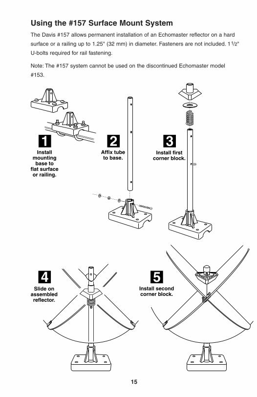
1 2 3Install
mounting base to
flat surfaceor railing.
Affix tube to base.
Install first corner block.
Using the #157 Surface Mount SystemThe Davis #157 allows permanent installation of an Echomaster reflector on a hard
surface or a railing up to 1.25" (32 mm) in diameter. Fasteners are not included. 11/2"
U-bolts required for rail fastening.
Note: The #157 system cannot be used on the discontinued Echomaster model
#153.
4Slide on
assembled reflector.
5Install second corner block.
Replacement PartsEchomaster replacement parts may be
obtained from your dealer or Davis
Instruments.
Echomaster 152,Standard
#R152FCorner Latches and Rivets (3 each)
#R155ERadar Reflector Booklet
Echomaster MaintenanceIf any reflector plates should become
bent, flatten them as well as possible in
order to obtain the high reflective per-
formance for which the Echomaster
has been designed.
The plates should be washed free of
salt water occasionally.
WARNING: No matter what method
was employed to mount the
Echomaster, it is the responsibility of
the user to make periodic inspections
of lines and fittings to insure that no
condition is developing which could
lead to mounting failure and possible
injury.
Davis Instruments wishes you many
years of happy and safe boating with
your advanced design Echomaster
Radar Reflector.
3465 Diablo Ave., Hayward, CA 94545 U.S.A.Phone (510) 732-9229 • Fax (510) 732-9188
[email protected] www.davisnet.com
00155.010, Rev. G January 2009© Copyright 2009 Davis Instruments Corporation
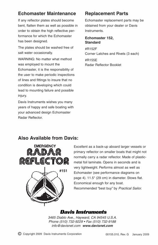
Also Available from Davis:
Excellent as a back-up aboard larger vessels or
primary reflector on smaller boats that might not
normally carry a radar reflector. Made of plastic-
metal foil laminate. Opens in seconds and is
very lightweight. Performs almost as well as
Echomaster (see performance diagrams on
page 4). 11.5" (29 cm) in diameter. Stows flat.
Economical enough for any boat.
Recommended “best buy” by Practical Sailor.
#151