features applications wearable electronic & iot devices...
TRANSCRIPT
Feb-17
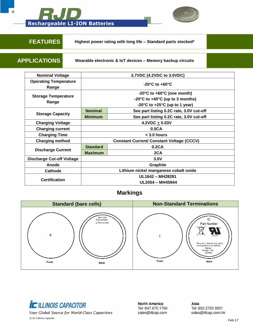
FEATURES Highest power rating with long life – Standard parts stocked*
APPLICATIONS Wearable electronic & IoT devices – Memory backup circuits
Nominal Voltage 3.7VDC (4.2VDC to 3.0VDC)
Operating Temperature
Range -20°C to +60°C
Storage Temperature
Range
-20°C to +60°C (one month)
-20°C to +40°C (up to 3 months)
-20°C to +25°C (up to 1 year)
Storage Capacity Nominal See part listing 0.2C rate, 3.0V cut-off
Minimum See part listing 0.2C rate, 3.0V cut-off
Charging Voltage 4.2VDC + 0.03V
Charging current 0.5CA
Charging Time < 3.0 hours
Charging method Constant Current/ Constant Voltage (CCCV)
Discharge Current Standard 0.2CA
Maximum 2CA
Discharge Cut-off Voltage 3.0V
Anode Graphite
Cathode Lithium nickel manganese cobalt oxide
Certification UL1642 – MH28281
UL2054 – MH45944
Markings
Standard (bare cells) Non-Standard Terminations

Feb-17
Standard Coin Cell Options
IC
Part
Number
Capacity
(mAh) Charging
Current
(mA)
Discharge
Current
(mA)
Maximum
Internal
Resistance
(mΩ)
Weight
(G)
Maximum
Diameter
(mm)
Height
(mm) Nom. Min.
STD MAX
RJD2032C1 85 80 40 17 170 600 3.4 20 3.5
RJD2048 120 110 60 24 240 700 4.2 20 5.0
RJD2430C1 110 104 55 22 220 500 4.5 24.5 3.15
RJD2440 150 140 75 30 300 700 5.4 24.5 4.3
RJD2450 200 190 100 40 400 500 6.5 24.5 5.4
RJD3032 200 190 100 40 400 600 7.2 30 3.4
RJD3048 300 290 150 60 600 400 9.3 30 4.8
RJD3555 500 490 250 100 1000 200 14 35.2 5.7
Standard PCM & Connector Options
IC
Part
Number
Capacity
(mAh) Charging
Current
(mA)
Discharge
Current
(mA)
Maximum
Internal
Resistance
(mΩ)
Weight
(G)
Maximum
Diameter
(mm)
Height
(mm) Nom. Min.
STD MAX
RJD3032HPPV30M 200 190 100 40 400 600 7.2 30 3.4
RJD3048HPPV30M 300 290 150 60 600 400 9.3 30 4.8
RJD3555HPPV30M 500 490 250 100 1000 200 14 35.2 5.7
Standard Leaded Options
IC
Part
Number
Capacity
(mAh) Charging
Current
(mA)
Discharge
Current
(mA)
Maximum
Internal
Resistance
(mΩ)
Weight
(G)
Maximum
Diameter
(mm)
Height
(mm) Nom. Min.
STD MAX
RJD2032C1ST1 85 80 40 17 170 600 3.4 20 3.5
RJD2048ST1 120 110 60 24 240 700 4.2 20 5.0
RJD2430C1ST1 110 104 55 22 220 500 4.5 24.5 3.15
RJD2440ST1 150 140 75 30 300 700 5.4 24.5 4.3
RJD2450ST1 200 190 100 40 400 500 6.5 24.5 5.4
RJD3032ST1 200 190 100 40 400 600 7.2 30 3.4
RJD3048ST1 300 290 150 60 600 400 9.3 30 4.8
RJD3555ST1 500 490 250 100 1000 200 14 35.2 5.7

Feb-17
Cell Dimensions
IC Part
Number
Fresh Cell Cycled cell
(after 500 cycles)
Shipping (Charged) Full Charge Full Charge
Maximum Diameter
(mm)
Maximum Height (mm)
Maximum Diameter
(mm)
Maximum Height (mm)
Maximum Diameter
(mm)
Maximum Height (mm)
RJD2032C1* 20 3.5 20 3.6 20 3.7
RJD2048* 20 5 20 5.2 20 5.3
RJD2430C1* 24.5 3.15 24.5 3.25 24.5 3.3
RJD2440* 24.5 4.3 24.5 4.4 24.5 4.5
RJD2450* 24.5 5.4 24.5 5.5 24.5 5.6
RJD3032* 30 3.4 30 3.5 30 3.6
RJD3048* 30 4.8 30 4.9 30 5.2
RJD3555* 35.2 5.7 35.2 5.8 35.2 5.9
*Same cell dimensions for PCM and leaded options
Part Numbering RJD 2032C1 A B C D E Section 1 Section 2 Section 3 Section 4 Section 5 Section 6 Section 1 – IC standard part number (Bare cell) Section 2 –Termination style
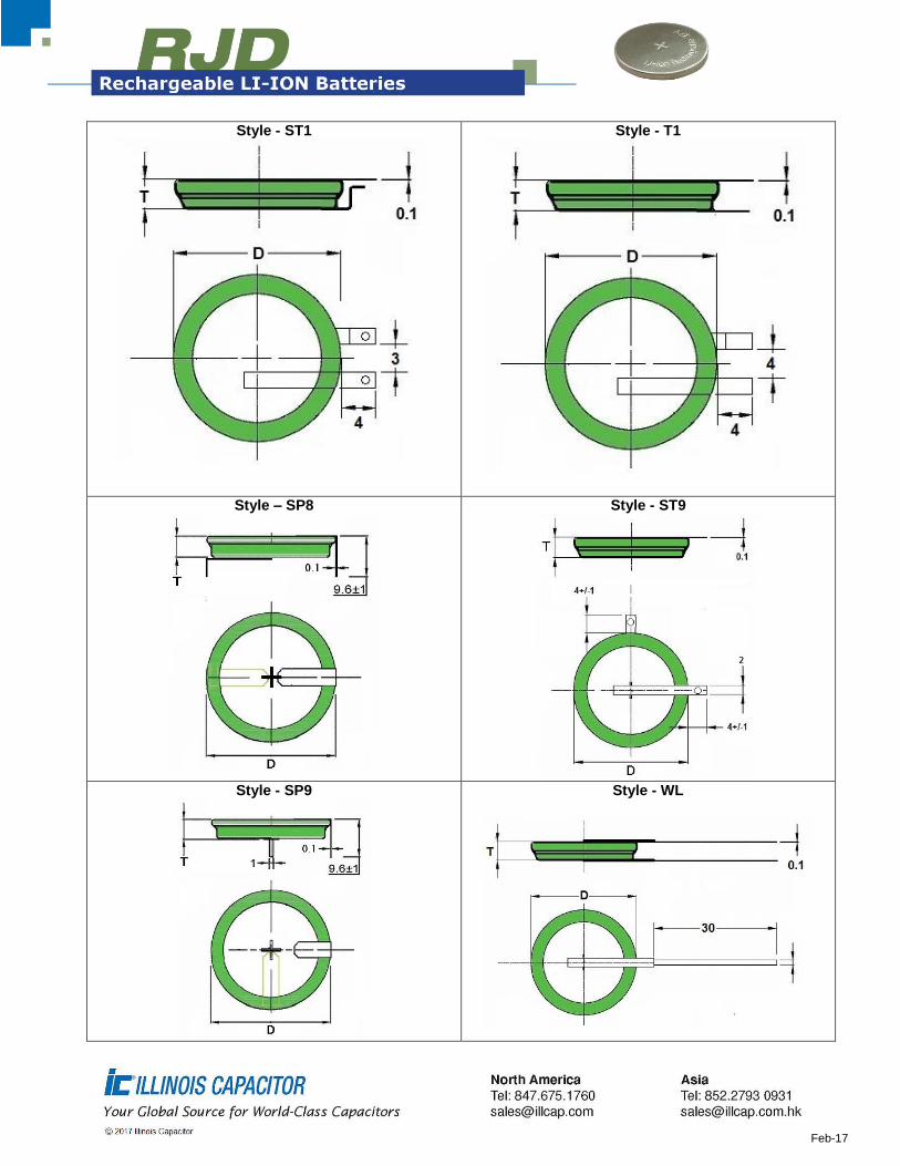
Termination Styles
Contact IC for detailed drawings
Bare Cell - (Standard)
Style - T0
Feb-17
Style - ST1
Style - T1
Style – SP8
Style - ST9
Style - SP9
Style - WL
Feb-17
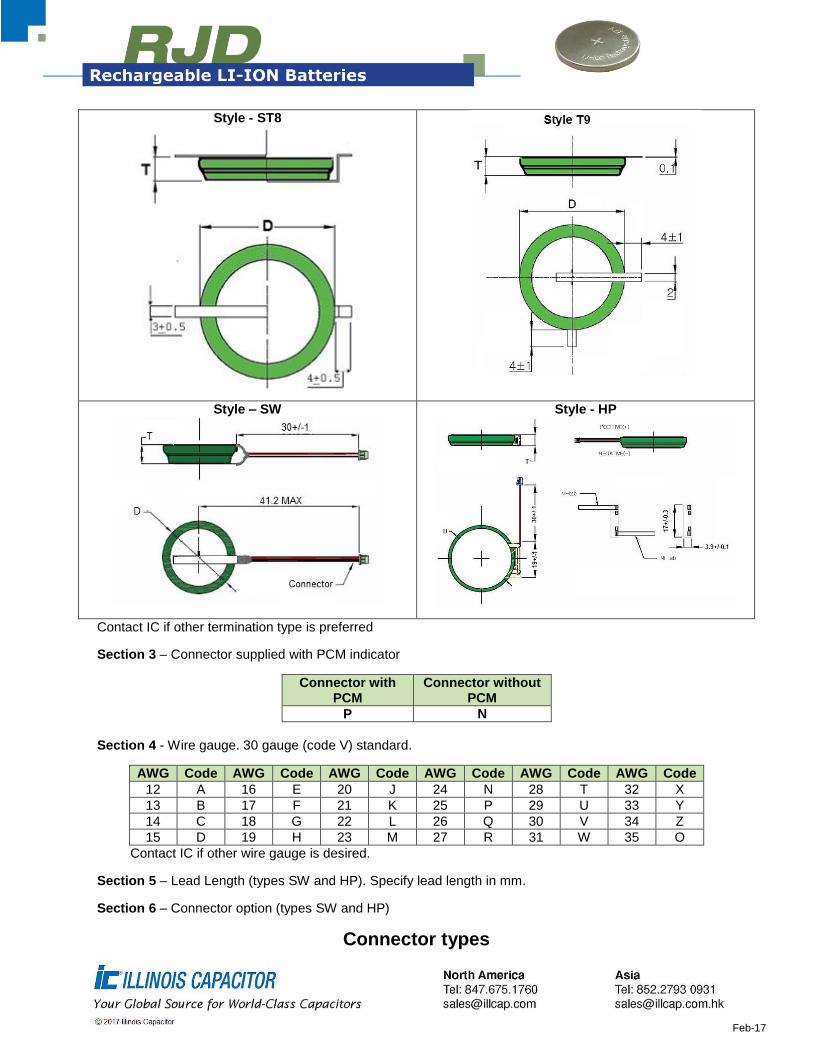
Style - ST8
Style – SW
Style - HP
Contact IC if other termination type is preferred
Section 3 – Connector supplied with PCM indicator
Connector with PCM
Connector without PCM
P N
Section 4 - Wire gauge. 30 gauge (code V) standard.
AWG Code AWG Code AWG Code AWG Code AWG Code AWG Code
12 A 16 E 20 J 24 N 28 T 32 X
13 B 17 F 21 K 25 P 29 U 33 Y
14 C 18 G 22 L 26 Q 30 V 34 Z
15 D 19 H 23 M 27 R 31 W 35 O
Contact IC if other wire gauge is desired.
Section 5 – Lead Length (types SW and HP). Specify lead length in mm.
Section 6 – Connector option (types SW and HP)
Connector types
Feb-17
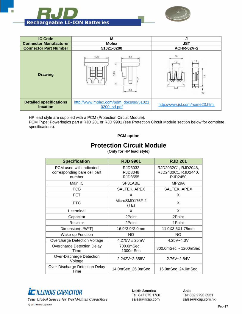
IC Code M J
Connector Manufacturer Molex JST
Connector Part Number 51021-0200 ACHR-02V-S
Drawing
Detailed specifications location
http://www.molex.com/pdm_docs/sd/510210200_sd.pdf
http://www.jst.com/home23.html
HP lead style are supplied with a PCM (Protection Circuit Module). PCM Type: Powerlogics part # RJD 201 or RJD 9901 (see Protection Circuit Module section below for complete specifications).
PCM option
Protection Circuit Module (Only for HP lead style)
Specification RJD 9901 RJD 201
PCM used with indicated corresponding bare cell part
number
RJD3032 RJD3048 RJD3555
RJD2032C1, RJD2048, RJD2430C1, RJD2440,
RJD2450
Main IC SP31ABE MP29A
PCB SALTEK, APEX SALTEK, APEX
FET X X
PTC MicroSMD175F-2
(TE) X
L terminal X X
Capacitor 2Point 2Point
Resistor 2Point 1Point
Dimension(L*W*T) 16.9*3.9*2.0mm 11.0X3.5X1.75mm
Wake-up Function NO NO
Overcharge Detection Voltage 4.275V ± 25mV 4.25V~4.3V
Overcharge Detection Delay Time
700.0mSec ~ 1300mSec
800.0mSec ~ 1200mSec
Over-Discharge Detection Voltage
2.242V~2.358V 2.76V~2.84V
Over-Discharge Detection Delay Time
14.0mSec~26.0mSec 16.0mSec~24.0mSec
Feb-17
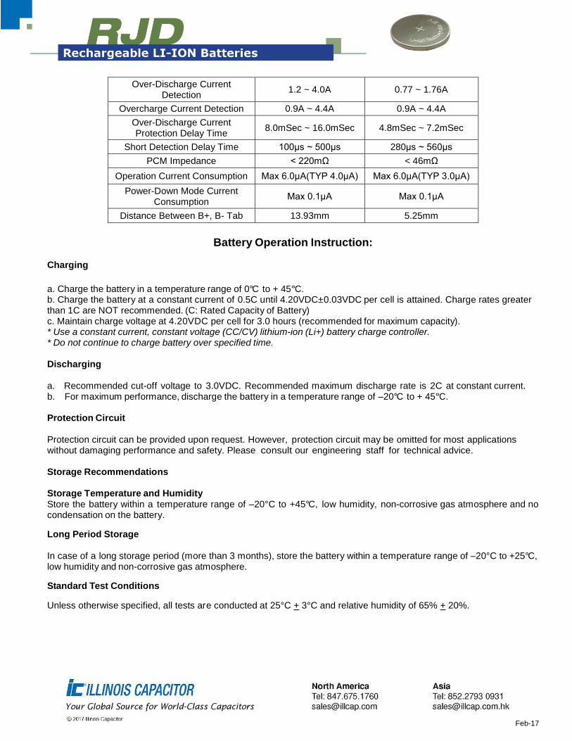
Over-Discharge Current Detection
1.2 ~ 4.0A 0.77 ~ 1.76A
Overcharge Current Detection 0.9A ~ 4.4A 0.9A ~ 4.4A
Over-Discharge Current Protection Delay Time
8.0mSec ~ 16.0mSec 4.8mSec ~ 7.2mSec
Short Detection Delay Time 100μs ~ 500μs 280μs ~ 560μs
PCM Impedance < 220mΩ < 46mΩ
Operation Current Consumption Max 6.0μA(TYP 4.0μA) Max 6.0μA(TYP 3.0μA)
Power-Down Mode Current Consumption
Max 0.1μA Max 0.1μA
Distance Between B+, B- Tab 13.93mm 5.25mm
Battery Operation Instruction:
Charging
a. Charge the battery in a temperature range of 0°C to + 45°C. b. Charge the battery at a constant current of 0.5C until 4.20VDC±0.03VDC per cell is attained. Charge rates greater than 1C are NOT recommended. (C: Rated Capacity of Battery) c. Maintain charge voltage at 4.20VDC per cell for 3.0 hours (recommended for maximum capacity). * Use a constant current, constant voltage (CC/CV) lithium-ion (Li+) battery charge controller. * Do not continue to charge battery over specified time. Discharging a. Recommended cut-off voltage to 3.0VDC. Recommended maximum discharge rate is 2C at constant current. b. For maximum performance, discharge the battery in a temperature range of –20°C to + 45°C. Protection Circuit Protection circuit can be provided upon request. However, protection circuit may be omitted for most applications without damaging performance and safety. Please consult our engineering staff for technical advice. Storage Recommendations Storage Temperature and Humidity
Store the battery within a temperature range of –20°C to +45°C, low humidity, non-corrosive gas atmosphere and no condensation on the battery.
Long Period Storage
In case of a long storage period (more than 3 months), store the battery within a temperature range of –20°C to +25°C, low humidity and non-corrosive gas atmosphere.
Standard Test Conditions
Unless otherwise specified, all tests are conducted at 25°C + 3°C and relative humidity of 65% + 20%.
Feb-17
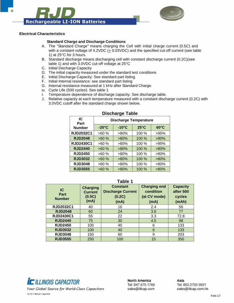
Electrical Characteristics
Standard Charge and Discharge Conditions A. The "Standard Charge" means charging the Cell with initial charge current (0.5C) and
with a constant voltage of 4.2VDC (+ 0.03VDC) and the specified cut-off current (see table 1) at 25°C for 3 hours.
B. Standard discharge means discharging cell with constant discharge current (0.2C)(see table 1) and with 3.0VDC cut-off voltage at 25°C
C. Initial Discharge Capacity D. The initial capacity measured under the standard test conditions E. Initial Discharge Capacity: See standard part listing F. Initial Internal resistance: see standard part listing G. Internal resistance measured at 1 kHz after Standard Charge.
H. Cycle Life (500 cycles): See table 1 I. Temperature dependence of discharge capacity. See discharge table. J. Relative capacity at each temperature measured with a constant discharge current (0.2C) with
3.0VDC cutoff after the standard charge shown below.
Discharge Table
IC Part
Number
Discharge Temperature
-20°C -10°C 25°C 60°C
RJD2032C1 >60 % >80% 100 % >95%
RJD2048 >60 % >80% 100 % >80%
RJD2430C1 >60 % >80% 100 % >95%
RJD2440 >60 % >80% 100 % >80%
RJD2450 >60 % >80% 100 % >80%
RJD3032 >60 % >80% 100 % >80%
RJD3048 >60 % >80% 100 % >80%
RJD3555 >60 % >80% 100 % >80%
Table 1
IC Part
Number
Charging Current (0.5C) (mA)
Constant
Discharge Current
(0.2C)
(mA)
Charging end
condition
(at CV mode)
(mA)
Capacity
after 500
cycles
(mAh)
RJD2032C1 40 16 2.4 56
RJD2048 60 24 3.6 77
RJD2430C1 55 22 3.3 72.8
RJD2440 75 30 4.5 98
RJD2450 100 40 6 133
RJD3032 100 40 6 133
RJD3048 150 60 9 203
RJD3555 250 100 15 350

Feb-17
Discharge Characteristics on Current Load (C-Rate)
Relative capacity at each load, measured with constant discharge current 0.2C, 0.5C, 1.0C, 2C with 3.0VDC cut-off after Standard Charge shown below.
Charge Current Discharge Current
Standard Charge 0.2 CA 0.5 CA 1 CA 2.0 CA
100 % > 95 % > 90 % > 50%
Shipment
The Cell shall be shipped with 30% of the nominal voltage. (Nominal Cell voltage range: 3.7 ~ 3.8 V). 30% SOC is only for air transport.
Storage Characteristics
After storage at the conditions listed below, the battery is measured at the standard charge and discharge conditions stated under the electrical characteristics.
Storage Condition Charge State Capacity Retention
Capacity Recovery
20 days at 60oC Shipping charge - > 85%
20 days at 60oC Full charge > 70% > 85%
60 days at 60oC Full charge > 40% > 60%
30 days at 60oC, 90%RH Full charge > 40% > 70%
Safety Test
Test Test Method Criteria
High Temperature Storing a cell at 90°C for 4 hours after being charged to 4.2VDC
No leakage
High Temperature and High Humidity
Storing a cell at 60°C and 90% RH for 1 week after being charged to 4.2VDC
No leakage
Thermal Shock Test
Store a fully charged cell (4.2VDC) at 60°C for 2 hours then at -20°C for 2 hours. 10 cycles with a maximum transition time of 5 minutes.
No leakage
Hot Box Test
A cell is to be heated in a gravity convection oven. The temperature of the oven is to be raised 5°C+/- 2°C per minute to a temperature of 130°C and remain at that temperature for 10 minutes
No explosion, No fire
Overcharge Test Charge the test samples with constant current (3C) and voltage 4.5VDC. Test samples remain on test for 2.5 hours
No explosion, No fire
Impact Test A test cell is to be placed on a flat surface. The bar of 9.1 kg weight and 15.8 mm diameter is dropped from a height of 610 mm onto the cell.
No explosion, No fire

Feb-17
Short-Circuit Test
A cell is to be short-circuited by connecting the positive and negative terminals of the battery with copper wire having a maximum resistance load of 100mΩ.
No fire or explosion, until battery is completely
discharged
Nail Test A stainless steel nail having a diameter of 4.0 mm is punched through the cell until the nail has passed through the opposite side of the cell.
No explosion, No fire
Applying Pressure Placing pressure on entire surface of a fully charged cell with 7kg for 72 hours
No leakage, No weight decrease
Precautions and Safety Instructions
Lithium-Ion rechargeable batteries subjected to abusive conditions can become damaged and/or cause personal injury. Please read and observe the standard battery precautions below before using.
Note 1. The customer is required to contact Illinois Capacitor in advance, if and when the customer needs other applications or operating conditions other than those described in this document. Note 2. Illinois Capacitor will take no responsibility for any accident where the cell is used under other conditions than those described in this document.
Precautions and Safety Instructions:
a. Do not expose the battery to extreme heat or flame. b. Do not short circuit, over-charge or over-discharge the battery. c. Do not subject the battery to strong mechanical shocks. d. Do not immerse the battery in water or sea water, or get it wet. e. Do not reverse the polarity of the battery for any reason. f. Do not disassemble or modify the battery. g. Do not remove charge/discharge protection circuitry. h. Do not handle or store with metallic objects like necklaces, coins or hairpins, etc. i. Do not use the battery if possible damage or deformation is present. j. Do not connect battery to the plug socket or car-cigarette-plug. k. Do not directly solder onto the battery. Only spot weld lead onto battery. Soldering iron temperature should be
limited to 350°C with a soldering time of <5 seconds. l. Do not place batteries in a solder bath. m. Do not touch a leaked battery directly. n. D o not use for other equipment. o. Do not mix Lithium-ion batteries. p. Do not use or leave the battery in direct sunlight (or in heated car by sunshine). q. Keep battery away from children. r. Use only the specified charger and observe charging requirement. s. Do not drive a nail into battery or strike battery with another battery or insert a screw into the battery t. Do not smash or throw battery. u. Recharge the battery every 6 months. v. Follow recommended charging conditions when charging battery.
Warnings:
a. Do not swallow. Keep out of reach of infants and children. If swallowed call physician immediately. b. Do not put battery in microwave or pressure cooker. c. Do not use battery together with a primary battery, such as dry battery types or batteries with different
capacities.

Feb-17
d. Do not replace battery with a different type or model.
e. Discontinue use of battery if an unusual odor, discoloration, deformation, internal heating or other unusual
characteristic changes are detected.
f. Do not have any leaked electrolyte come in contact with eyes. If contact occurs flush eyes immediately with
water and consult a doctor.
g. If charging does not stop after expected charging time, stop charging battery.
Requirement for Safety Assurance
For safety assurance, please discuss the equipment design, its system and protection circuit of Lithium-ion battery with Illinois capacitor in advance.
Consult with Illinois Capacitor about high rate current, rapid charge and special application.