featured article establishing a mechanical … · to equipment within the scope of coverage as...
TRANSCRIPT

VOLUME 23, ISSUE 5
SEPTEMBER | OCTOBER 2017
A S S E T I N T E G R I T Y I N T E L L I G E N C E
Fe atured Article
ESTABLISHING A MECHANICAL INTEGRITY PROGRAM FOR FIRED HEATER TUBESARUN SREERANGANATHAN, Materials Engineering Consultant at Stress Engineering Services JOHN NORRIS, Staff Consultant at Stress Engineering Services

2 Inspectioneering Journal SEPTEMBER | OCTOBER 2017
ESTABLISHING A MECHANICAL INTEGRITY PROGRAM FOR FIRED HEATER TUBES
BY: ARUN SREERANGANATHAN, Materials Engineering Consultant at Stress Engineering Services JOHN NORRIS, Staff Consultant at Stress Engineering Services
INTRODUCTIONFired heaters are among the most critical equipment in refin-eries and chemical plants. Owing to the criticality of the equip-ment, tube failures in fired heaters present significant safety and financial impacts to the owner/operator. A mechanical integrity program is warranted to reduce the risk of failures. This article provides a general overview of the tasks that can be included in an effective mechanical integrity program for tubes in fired heat-ers. The article is intended to be a general outline, applicable to the majority of fired heaters.
It is noted that for the purposes of this article, “Fired Heaters” apply to equipment within the scope of coverage as defined in the API STD 560, “Fired Heaters for General Refinery Service,” with the tubes designed as required in API STD 530, “Calculation of Heater-tube Thickness in Petroleum Refineries.” Currently, this method is meant for refiner-ies and some petrochemical services, but does not include alloys outside the coverage of API 530, such as used in steam methane reformer furnaces.
OVERVIEW OF HEATER TUBE DESIGN AND FITNESS-FOR-SERVICE CONSIDERATIONSThe design criteria for calculat-ing the required wall thickness of new tubes in fired heaters is governed by API 530, whereas Fitness-For-Service (FFS) calcula-tions of service-exposed tubes are typically carried out per API 579-1/ASME FFS-1 procedures.
There are two different design considerations for heater tubes: elastic design and creep-rupture design. Elastic design is based on preventing bursting of the tubes due to short-term exposure (time-independent) to excessive stresses (greater than the yield strength of the material) at lower temperatures. In contrast, creep-rupture design is based on preventing failures under long-term exposure (time-dependent) to lower-than-yield stresses at higher temperatures. Creep being a time-dependent damage mechanism, creep-rupture design has to take into consideration the minimum intended life for heater tubes during the design stage. API 530 tubes are typically designed for 100,000 hours using the minimum expected creep properties for the tube mate-rial of construction.
The remaining life of a service-exposed heater tube can be con-trolled by (a) the creep-rupture life; (b) the elastic life; or (c) the tube retirement thickness set by the owner/operator. For heater tubes operating at temperatures high enough for the effects of creep to be significant, the remaining life is typically controlled by creep-rupture, unless there is significant corrosion or oxida-tion in the tubes. High corrosion rates, coupled with high relief valve set pressures, can cause the elastic design to govern even at higher temperatures. Corrosion is the controlling damage mecha-nism if the elastic design governs the tube life at a given tempera-ture and pressure. Similarly, the tubes are expected to fail by creep if the tube life is governed by creep-rupture design. A third factor that may end up controlling the remaining life of a used heater tube is the retirement thickness set for the tube, which is again determined by dead loads and corrosion. API 530 does not provide
any recommendations for tube retirement thickness and it is up to the owner to set a retire-ment thickness. Remaining life calculations based on API 579-1 do not take into account the retirement thickness set by the owner. In cases where tubes exhibit corrosion and the heater design/operating con-ditions are such that the tubes do not experience significant creep and has a low relief valve set pressure, the tubes may be paper thin by the time they fail
by creep or by exceeding the elastic allowable stress (i.e., over-pressure). In such cases, it makes practical sense to establish an overriding retirement thickness irrespective of the creep damage.
API 579-1 provides a limiting minimum wall thickness for pres-sure vessel and piping components, but not specifically for heater tubes (Table 4.4, API 579-1 2016 Ed.). The limiting wall thickness is the higher of (a) 20% of the nominal wall thickness; and (b) 0.10” for pressure vessels. For piping components, API 579-1 specifies the highest of (a) 20% of the nominal wall thickness; or (b) 0.05” as limiting wall thickness. To the best of the authors’ knowledge, most US refineries and chemical plants use 0.10” to 0.13” as the retirement thickness for heater tubes.
Note that other damage mechanisms such as carburization, sigma phase embrittlement, stress corrosion cracking, etc., while not discussed in the previous paragraphs, may end up governing the tube life in some cases.
[...] tube failures in fired heaters
present significant safety and
financial impacts to the owner/
operator. A mechanical integrity
program is warranted to reduce
the risk of failures.

SEPTEMBER | OCTOBER 2017 Inspectioneering Journal 3
MECHANICAL INTEGRITY PROGRAM
Equipment and Personnel Identification
The first task for any equipment specific mechanical integrity program is to identify the total population of equipment to be included. For better execution efficiencies, obvious grouping by process area, service, materials of construction, etc. may be employed. The second task is to identify the interested or affected parties. These include, but are not limited to:
• Unit Engineer responsible for the reliability or mechanical integrity of the asset (generally a Mechanical Engineer).
• Unit Engineer responsible for the throughput or perfor-mance of the asset (generally a Chemical or Process Engineer but can be different depending on the facility).
• Unit Inspector responsible for the asset.
Service and Damage Mechanism Review
Once the equipment to be included has been identified, the next step is to perform a thorough review of the process location, materials of construction, and known and expected damage mechanisms. The review should consist of the following:
• Location and function in the process
• Normal expectations for pressure and temperature
• Historical temperature and pressure exposure, excursions; severity, frequency, start-ups/shut-downs, etc.
• Notations from operator rounds or logs
• Notations and findings from inspection records
• Notable events; fires, removal from and later returned to service, near misses
• Design and/or service changes
• Date of and findings from last internal inspection
• Anticipated date of next outage or turn around (T/A) opportunity
• Desired T/A interval
Based on the results of the review, the type/s of potential dam-age mechanisms, the type and coverage for dimensional checks, measurements, and non-destructive examination (NDE) for each heater or heater section should be identified.
Initial Screening Assessment
For each heater, the equipment and inspection records should be reviewed to determine the design basis, past operating practices and integrity operating windows with out of range operations noted. The following generally summarizes the information required for an assessment of the tubes in fired heaters:
• Number of different coils
• Coil description(s) (i.e., Radiant, Convection, Other)
• Variations in geometry and materials for each coil
• For each unique design of each coil determine the following:
° Tube geometry; O.D., nominal thickness, AW or MW
° Material; product form, type or grade
° Replacement history
° Thickness records and corrosion rate
° Current thickness (t-insp); most recent measured and quantifiable corrosion or other damage accumulation rate.
° Elastic design pressure and tube metal temperature (TMT) associated with the elastic design pressure
° Elastic Design
- Calculate minimum required thickness (t-min) for elastic design
- Compare t-min to t-insp and note any deficiencies
° Rupture design pressure and tube metal temperature (TMT) associated with the rupture design pressure
° Maximum recorded tube skin temperature (T-worst) and internal pressure (P-worst)
° Preliminary Check Rupture Design
- Calculate total damage per API 579-1 Level 1 check using worst case assumptions—nominal stress based on lowest measured thickness and an internal pressure of P-worst , constant temperature of T-worst throughout the entire service history.
Detailed Screening Assessment
For each heater with a total damage factor greater than 0.25 from the API 579-1 Level 1 check, the available process records, instrumentation (process historian data), and inspection records, including infrared (IR scans) should be reviewed to determine the previous, current, and future anticipated operating conditions. Based on the determined operating conditions, one should deter-mine the total damage and estimated remaining life following an API 579-1 Level 2 assessment.
The initial target date for the remaining life calculations is the 2nd upcoming turnaround (T/A) opportunity (i.e., T/A after the next one scheduled). Based on the (per tube or tube sections) results of the Level 2 assessments one of the following categories can be assigned (best to worst):
1. Calculated remaining life, using minimum material properties, exceeds the target date by at least 2-1/4 years (~20,000hrs).
2. Calculated remaining life, using minimum material properties, is within 2-1/4 years before or after the target date.
3. Calculated remaining life, using minimum material properties, exceeds the next T/A by at least 2-1/4 years.
5. Calculated remaining life, using minimum material

4 Inspectioneering Journal SEPTEMBER | OCTOBER 2017
properties, is within 2-1/4 years before or after the next T/A.
6. Calculated remaining life, using minimum material proper-ties, is less than 2-1/4 years before the next T/A.
The 20,000 hours margin represents the lower end of accurate prediction for creep rupture per API 530. Calculated remaining lives less than 20,000 hours are not necessarily accurate, and as such, should not be relied upon.
The initial categorization assumes no previous accelerated creep testing tube data. Once actual tube data is available, the calcu-lations and categorizations can be made with a higher certainty.
Follow-up Actions
The follow-up actions during the next T/A vary for each of the above categories, though the following basic activities are recom-mended irrespective of the determined category:
• Perform the applicable dimensional checks and NDE for each tube or tube sections.
• Measure and update tube thickness and corrosion rate data.
• Depending on the potential damage mechanisms, field metal-lography or tube samples may be necessary to evaluate or monitor changes in the tube condition.
• Reevaluate the remaining life based on the updated data, assign category, and develop the potential scope and timing of tube replacements.
Additional activities that may be needed for each category are listed below:
Category – 1 (Activities for the Next T/A)
Tubes or tube sections in this category are unlikely to require replacement during the upcoming T/A and no additional activi-ties are recommended.
Category – 2 (Activities for the Next T/A)
Tubes or tube sections in this category are also unlikely to require replacement during the upcoming T/A. However, there is a chance that a few tubes may need to be replaced to increase the confidence of reaching the next T/A. Also, due to the lesser remaining life, additional data than previously collected is most likely necessary and should be planned for this T/A.
These tubes are a good candidate for accelerated creep testing to confirm the material properties unless this category was deter-mined after previous creep testing. Based on the results, the use of average material properties can be considered, before or with-out the results from accelerated creep testing, if the site accepts the increased risk of this method. The increased risk is due to the fact that without testing a probability exists that the tubes may not meet the average tube properties.
Category – 3 (Activities for the Next T/A)
Tubes or tube sections in this category are likely to require some tube replacements during the upcoming
T/A. Preparation for the scope (material, labor, etc.) should be included in the T/A plan. NDE results coupled with API 579-1 cal-culations can be used to aid in the selection of tubes targeted for replacement.
These tubes are a strong candidate for accelerated creep testing to confirm the material properties unless this category was deter-mined after previous creep testing. Based on the results, the use of average material properties can be considered, before or with-out the results from accelerated creep testing, if the site accepts the increased risk of this method. The increased risk is due to the fact that without testing a probability exists that the tubes may not meet the average tube properties.
Category – 4 (Activities for the Next T/A)
Tubes or tube sections in this category are very likely to require some tube replacements during the upcoming T/A. Preparation for the scope (material, labor, etc.) should be included in the T/A plan. NDE results coupled with API 579-1 calculations can be used to aid in the selection of tubes targeted for replace-ment. Upon determination of this category, the risk of continued operation should be reviewed and accepted by site management. This risk may be better quantified using a probabilistic approach for the remaining life calculations.
Perform accelerated creep testing to confirm the material prop-erties unless this category was determined after previous creep testing.
Category – 5 (Immediate Attention; Potentially Requiring Activities Before the Next T/A)
Tubes or tube sections in this category are very likely to require tube replacements before the next T/A. Preparation for the scope (material, labor, etc.) should be planned with a contingency for immediate execution. NDE results coupled with API 579-1 calcu-lations can be used to aid in the selection of tubes targeted for replacement. Upon determination of this category, the risk of continued operation should be reviewed and accepted by site management. This risk may be better quantified using a proba-bilistic approach for the remaining life calculations. As with the other categories, the following activities should be included in the planned scope of work practical:
Perform accelerated creep testing to confirm the material prop-erties unless this category was determined after previous creep testing.
METALLOGRAPHY AND ACCELERATED CREEP TESTING
At this point, it is worthwhile to discuss in detail two of the fol-low-up activities mentioned in the previous section, namely field metallography and creep testing.
Field Metallography
Field metallography is a non-destructive examination technique which involves in-situ metallographic preparation of a selected area on the tube and replication of the tube microstructure at
SEPTEMBER | OCTOBER 2017 Inspectioneering Journal 5
that location. This involves using an acetate tape to make a fine impression of the tube surface that can be examined in a lab. It is aimed at examining the tube OD surface microstructure for evi-dence of high temperature degradation including, but not limited to, creep voids and/or cracks. However, it should be noted that field metallography by itself is not necessarily a reliable indica-tor of creep damage in heater tubes. The first visible evidence of creep from a microstructural standpoint is often in the form of isolated grain-boundary voids. The creep voids eventually link up to form micro-fissures and, in later stages, macro-cracks that result in failure. However, creep voids and cracks may not appear until very late in the life of a tube, especially when the tube mate-rial has sufficient creep ductility. Accordingly, the chances of finding creep voids/cracks in a replica pulled from a heater tube are slight. In addition, field replicas are typically obtained under non-ideal conditions and the quality of replicas, however good, does not always lend itself to conclusively identifying creep voids and distinguishing the voids from other microstructural artifacts. Finally, the most obvious drawback of field metallography is that it can only identify damage that is present on the tube surface. It does not provide any information on through-thickness micro-structural variations, such as the extent of carburization in a tube that is subjected to the damage mechanism.
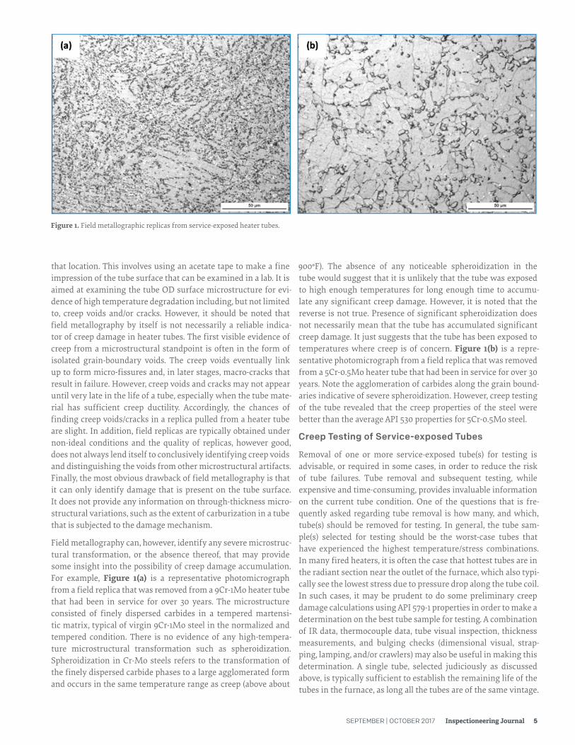
Field metallography can, however, identify any severe microstruc-tural transformation, or the absence thereof, that may provide some insight into the possibility of creep damage accumulation. For example, Figure 1(a) is a representative photomicrograph from a field replica that was removed from a 9Cr-1Mo heater tube that had been in service for over 30 years. The microstructure consisted of finely dispersed carbides in a tempered martensi-tic matrix, typical of virgin 9Cr-1Mo steel in the normalized and tempered condition. There is no evidence of any high-tempera-ture microstructural transformation such as spheroidization. Spheroidization in Cr-Mo steels refers to the transformation of the finely dispersed carbide phases to a large agglomerated form and occurs in the same temperature range as creep (above about
900°F). The absence of any noticeable spheroidization in the tube would suggest that it is unlikely that the tube was exposed to high enough temperatures for long enough time to accumu-late any significant creep damage. However, it is noted that the reverse is not true. Presence of significant spheroidization does not necessarily mean that the tube has accumulated significant creep damage. It just suggests that the tube has been exposed to temperatures where creep is of concern. Figure 1(b) is a repre-sentative photomicrograph from a field replica that was removed from a 5Cr-0.5Mo heater tube that had been in service for over 30 years. Note the agglomeration of carbides along the grain bound-aries indicative of severe spheroidization. However, creep testing of the tube revealed that the creep properties of the steel were better than the average API 530 properties for 5Cr-0.5Mo steel.
Creep Testing of Service-exposed Tubes
Removal of one or more service-exposed tube(s) for testing is advisable, or required in some cases, in order to reduce the risk of tube failures. Tube removal and subsequent testing, while expensive and time-consuming, provides invaluable information on the current tube condition. One of the questions that is fre-quently asked regarding tube removal is how many, and which, tube(s) should be removed for testing. In general, the tube sam-ple(s) selected for testing should be the worst-case tubes that have experienced the highest temperature/stress combinations. In many fired heaters, it is often the case that hottest tubes are in the radiant section near the outlet of the furnace, which also typi-cally see the lowest stress due to pressure drop along the tube coil. In such cases, it may be prudent to do some preliminary creep damage calculations using API 579-1 properties in order to make a determination on the best tube sample for testing. A combination of IR data, thermocouple data, tube visual inspection, thickness measurements, and bulging checks (dimensional visual, strap-ping, lamping, and/or crawlers) may also be useful in making this determination. A single tube, selected judiciously as discussed above, is typically sufficient to establish the remaining life of the tubes in the furnace, as long all the tubes are of the same vintage.
Figure 1. Field metallographic replicas from service-exposed heater tubes.

6 Inspectioneering Journal SEPTEMBER | OCTOBER 2017
Once the tube for removal has been identified, it is important the tube is clearly marked prior to removal with information including location in the heater (furnace number, pass, elevation, distance to closest thermocouple, etc.), and tube orientation (fire-side, wall-side, etc.).
In addition to creep testing, tube removal also allows for metallo-graphic analysis of the tube in cross-section which provides more information than what surface replication can provide us (carbu-rization depth, ID surface damage, etc.)
Creep testing of service-exposed tube(s) can be carried out to determine the creep properties of the tube material at the current point in time. The current properties of the tube material are influ-enced by (a) creep properties of the virgin material before the tube was put in service; and (b) creep damage accumulated by the tube material in service, if any. The test results, in conjunction with the creep data provided in API 579-1/ASME FFS-1 2016 (API 579-1) for the tube material, can be used to quantify the creep damage accumulated in the tube material and predict the remaining life at the future operating conditions. API 579-1 provides creep data for common tube materials from three different sources: (a) MPC Project Omega; (b) API Std 530, 6th Edition; and (c) WRC Bulletin 541, 2nd Edition.
The MPC Project Omega methodology is based on the observation that the service conditions (stress and temperature) of common engineering alloys used in the refining and petrochemical indus-tries are such that the majority of the life is spent in the tertiary creep regime. Creep testing per Omega methodology aims at esti-mating two parameters, strain rate parameter (initial creep rate) and damage parameter (Omega), which may be used to predict the remaining life. Note that these parameters can only be measured after the test gets to the tertiary creep regime. The mea-sured Omega parameters capture the creep properties of the tube in the service-exposed condition. The Omega parameters can be obtained from the test data by fitting the strain vs. time curve from the tests using the equation
API 530, 6th Edition (Calculation of Heater-tube Thickness in Petroleum Refineries) uses creep rupture data collected in the US in the 1960’s and 1970’s, with the data presented as minimum and average stress rupture properties using a time-temperature parameter (Larson-Miller). WRC 541 also uses creep rupture data, but the data sources are more recent and include test results for materials produced and tested at facilities outside of the United States. The 7th Edition of API 530 has adopted the WRC 541 data as first published in 2013.
When testing service-exposed material, the testing can be ter-minated once and can be accurately measured (which may require testing times in excess of 50% of the life at the test conditions) when using the MPC Project Omega methodology. For API 530/WRC 541 based calculations, the tests may either be continued to rupture or the rupture time can be estimated using Equation 2. The rupture times, in conjunction with API 579-1 data for the tube material, can be used to establish an LMP curve specific to the service-exposed tube that is being tested. The LMP curve thus derived, similar to the Omega parameters, captures creep degradation in the material from service, if any. Remaining life calculations may be carried out using the Omega parameters or LMP curves obtained from the tests per method-ologies outlined in API 579-1, Part 10.
CONCLUDING REMARKS
As stated in the beginning, this document provides a general outline for a mechanical integrity program for fired heaters. Additional inputs/activities may be necessary in specific cases. When coupled with the development and implementation of integrity operating windows (IOWs), establishment of such a mechanical integrity program for fired heaters can increase the reliability of the corresponding process units by reducing the risk of tube failures. n
For more information on this subject or the author, please email us at [email protected].
REFERENCES
1. API Standard 560, “Fired Heaters for General Refinery Service”, 5th Edition, 2016.
2. API Standard 530, “Calculation of Heater-tube Thickness in Petroleum Refineries”. 7th Edition, 2015.
3. API 579-1/ASME FFS-1, “Fitness-For-Service”, 2016.
4. WRC Bulletin 541, “Evaluation of Material Strength Data for Use in API Std 530”, 2nd Edition, 2015.
where is the initial creep rate; and is the Omega parame-ter. Once the and are established from a test, the time to rupture can be estimated using the equation
Equation 1.
Equation 2.

SEPTEMBER | OCTOBER 2017 Inspectioneering Journal 7
CONTRIBUTING AUTHORS
JOHN NORRIS John Norris joined Stress Engineering Services as a Staff Consultant in 2014 after a 25-year
career in plant engineering and pressure vessel design. Prior to Stress Engineering, John
worked as a fixed-equipment engineer for ConocoPhillips and Phillips 66, plant engineering
supervisor for Louisiana Pigment Co., maintenance engineer for Levington Engineers Inc.,
assistant plant manager, engineering supervisor, and engineering coordinator for Ohmstede
Inc., and manufacturing engineer for IMO Industries, after obtaining a BS in Mechanical
Engineering from Louisiana Technical University. John is a Registered Professional Engineer
in Louisiana and Texas.
ARUN SREERANGANATHAN
Arun Sreeranganathan holds a BS degree in Metallurgical Engineering from NIT Jaipur (India),
an MS from National University of Singapore under Singapore-MIT Alliance Program, and a
PhD in Materials Science and Engineering from Georgia Tech. He joined Stress Engineering
Services in 2008 after completing his PhD and has been involved with mechanical integrity,
materials, metallurgy, and creep-related problems affecting various industries. He is a
licensed professional engineer in the State of Louisiana.
