feature-based, surface and direct modeling: an · pdf filemoreover, the surface modeling...
TRANSCRIPT

Abstract—Aim of this paper is to analyse and compare the
characteristics of Feature Based and Direct Modeling
techniques to determine their pros and cons for typical design
processes. The first is one of the most common approach to
create CAD models to be used for the machining phase of
mechanical parts and assemblies. The second is a new method,
alternative to the first one, based on a user-friendly approach,
without rigid rules and constraints, that could represent the
future of the CAD methodologies. Moreover, the Surface
Modeling approach is analyzed and compared to the others,
due to its common use in automotive and aeronautics fields.
Considering the Feature Based Modeling as benchmark, three
case studies were analysed to examine the peculiarities of these
techniques, and to determine and highlight their advantages
and their drawbacks. Several aspects were contemplated to
perform the tests: the execution time for the realization of each
operation, the easiness to create features and geometries, the
possibility to adequately modify and upgrade the models and
the number of operations needed to get the complete virtual
prototype.
In the end, the results were analysed and discussed focusing
the attention on the possibility to adopt the Direct Modeling as
substitute of the Feature Based and/or Surface Modeling and of
the current CAD techniques.
Index Terms—Direct Modeling, Feature Based Modeling,
CAD, Surface Modeling, Virtual Prototyping, Top-Down
Approach, Main Landing Gear, Wing, Fuselage
I. INTRODUCTION
OWADAYS the Virtual Prototyping (VP) techniques are
fundamental for the design and the production
processes. They allow to use digital models in virtual
environments to simulate the behaviour and the
performances of a product not yet manufactured [1], [2].
The achievable results are often so accurate and realistic to
allow to choose the best design strategies to improve the
final model since the very starting steps of the production
process [2]. They are grounded on robust algorithms,
powerful software and user friendly tools that assist and
guide the designer to the best solution. One of the most
important among the VP techniques is the CAD modeling,
that allows to generate the leading actor for each kind of
simulation i.e. a virtual model (Digital Mock-Up)
characterized by physical and mechanical properties. It can
be used for digital testing, FEM and Multiphysical analyses,
kinematical and dynamical simulations, etc. [3]. The VP
Manuscript received July 27, 2016; revised January 06, 2017.
F. Renno is with the Dipartimento di Ingegneria Industriale, Università
degli Studi di Napoli Federico II, Napoli, 80125 ITALY (corresponding
author, phone +390817682459; fax +390817682466; e-mail:
techniques are used in many cases, from computer graphics
(videogames and renderings) to educational, from medical
to industrial fields [3]-[9]. In the last years, they are
becoming very important for the design and the
development of the nuclear fusion plants and their devices
[10]-[15].
A (robust) CAD model can be created by means of
several tools and techniques. In particular, parametric (i.e.
NX, CREO, CATIA, etc.) and/or non-parametric (Rhino 3D,
3DS MAX, CINEMA 4D, MAYA, etc.) software can be used
[3]. One of the most common approach used to build solid
prototypes is the Feature Based Modeling (FBM) because of
the strong connection between the operations realized to
create the CAD model and the real sequence of mechanical
tasks done during the machining process. This technique is
based on sketches, constraints and rules and in many cases
complex models could be generated and cause problems
hard to manage.
In the last years, a new technique, called Direct Modeling,
is becoming very common due to its interesting
peculiarities. It allows to operate straightly on the geometry
without the analysis and the use of sketches and rules
making the modification of each kind of geometry easier.
Several Direct Modelers are available on the market (ANSYS
SpaceClaim, PTC Creo Direct, Autodesk Fusion 360)
demonstrating the growing interest reserved to this new
modeling technique by the most important CAD and FEM
companies. In particular, Direct Modeling, due to some
remarkable features and to the integration with the most
common 3D CAD and FEM software, could represent the
solution to some typical problems of the classical modeling
techniques. Furthermore, it might be a first step to win some
of the current challenges of the Geometric Modeling as the
virtualization of porous medium, or non-homogenous
materials in order to vary their density and composition. For
instance, it could allow to properly simulate complex
substances in biomedical applications [16]-[23].
So, main targets of this paper are: a) to analyse and
describe the main features of the Feature Based, Surface
and Direct Modeling, b) to make a comparison based on
some case studies developed to highlight pros and cons of
these approaches. Furthermore, due to the massive use of the
Surface and of the Feature Based Modeling in the aircraft
design, an aeronautic point view was considered.
The section II of the paper describes the main concepts of
the Geometric Modeling with particular attention to the
Feature Based Modeling. Sections III and IV analyses the
Direct and the Surface Modeling approaches. The case
studies to validate the methodologies used are presented in
the section V whereas the results are compared and shown
in section VI.
Feature-Based, Surface and Direct Modeling:
an Aeronautic Point of View
F. Renno
N
Engineering Letters, 25:2, EL_25_2_04
(Advance online publication: 24 May 2017)
______________________________________________________________________________________
II. GEOMETRIC MODELING
Geometric Modeling allows the mathematical description
of shapes. It is based on methods and algorithms
implemented to create the replica of objects by means of 2D
technical drawings and 3D MCAD in virtual environments.
So, it is possible to represent real models characterized by
volumetric information and physical properties like mass,
density, volume, etc., [3], [19], [24]. In this way, the
designer can realize multiphysics analyses with accurate
results starting from the use of specific software. For
instance, Computational Fluid Dynamics (CFD), Fluid
Structure Interaction (FSI), Electromagnetic (EM)
simulations or ultrarealistic renderings for visualization
purposes are possible [3], [16], [21].
Many CAD methodologies are available to create the
needed virtual prototypes. The most common are: Solid
Modeling, Surface Modeling, Sheet-Metal Design, Chunky
Modeling and so on [3], [16]. Probably, the best modeling
technique doesn’t exist. Only evaluating the pros and the
cons and so the “potential benefits” of each one it will be
possible to select the most appropriate choice to design and
realize the specific product.
Usually, in the industrial field, solid models characterized
by technical features (holes, cut-outs, rounds, etc.) are
requested. Whereas, when for styling purposes, profiles or
shapes properly designed and optimized are mandatory,
surface modeling is to be preferred.
Due to its common use, in this section solid modeling is
considered and in detail the Feature Based approach is
analysed.
Feature Based Modeling (FBM)
A model can be built by means of features. Features are
technological operations (extrusions, cut-outs, holes, fillets,
etc.) executed on the model. At present, FBM is one of the
most common techniques used to realize solid prototypes.
The CAD models are built starting from a base component
adding material to it or subtracting material from it. Each
mechanical operation can be strictly connected with CAD
features as extrusion, cut-out, revolve, chamfer and so on.
The list of operations has to be carefully planned by the
designer in order to properly define the interdependencies
between the features. Otherwise, in case of complex parts,
conflicts and errors could occur.
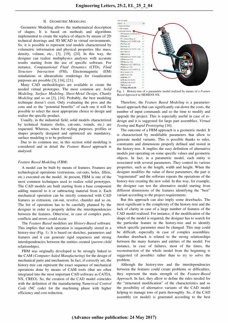
The Feature Based modelers are History-Based software.
This implies that each operation is sequentially stored in a
history-tree (Fig. 1). It is based on sketches, parameters and
features and it can generate rigid sequences and strong
interdependencies between the entities created (parent-child
relationships).
FBM was originally developed to be strongly linked to
the CAM (Computer Aided Manufacturing) for the design of
mechanical parts and mechanism. In fact, if correctly set, the
history-tree can represent the exact sequence of mechanical
operations done by means of CAM tools (that are often
integrated into the most important CAD software as CATIA,
NX, CREO). So, the creation of the CAD model coincides
with the definition of the manufacturing Numerical Control
Code (NC code) for the machining phase with higher
efficiency and cost reduction.
Fig. 1. History-tree of a parametric model realized by means of a Feature
Based Approach in SIEMENS NX.
Therefore, the Feature Based Modeling is a parameter-
based approach that can significantly cut-down the costs, the
number of input commands and so the time to modify and
upgrade the project. This is especially useful in case of re-
design and it is suggested for large part assemblies, Virtual
Testing and Rapid Prototyping [16].
The outcome of a FBM approach is a geometric model. It
is characterized by modifiable parameters that allow to
generate model variants. This is possible thanks to rules,
constraints and dimensions properly defined and stored in
the history-tree. It implies the easy definition of alternative
models just operating on some specific values and geometric
objects. In fact, in a parametric model, each entity is
associated with several parameters. They control its various
properties, such as the length, width and height. When the
designer modifies the value of these parameters, the part is
“regenerated” and the software repeats the operations of the
history-tree creating the new solid. In this way, for example,
the designer can test the alternative model starting from
different dimensions of the features identifying the “best”
variant according to the project requirements.
But this approach can also imply some drawbacks. The
most significant is the complexity of the history-tree and the
lack of clarity in case of a large number of features of the
CAD model realized. For instance, if the modification of the
shape of the model is required, the designer has to search for
the particular feature in the history-tree and to identify
which specific parameter must be changed. This step could
be difficult, especially in case of complex assemblies.
Another drawback is related to the strong relationships
between the many features and entities of the model. For
instance, in case of failures, most of the times, the
reconstruction of the whole model from the beginning is
suggested (if possible) rather than to try to solve the
problem.
Although the history-tree and the interdependencies
between the features could create problems or difficulties,
they represent the main strength of the Feature-Based
Approach. In fact, they allow to define the rules needed for
the “structured modification” of the characteristics and so
the possibility of alternative variants of the CAD model
helping to manage tons of parts thoroughly. So, if the CAD
assembly (or model) is generated according to the best
Engineering Letters, 25:2, EL_25_2_04
(Advance online publication: 24 May 2017)
______________________________________________________________________________________

practices of the Top-Down modeling and is based on proper
skeletons and reference systems, the result will be robust
enough respect to each kind of failure [24].
III. SURFACE MODELING
It allows to define and visualize the external parts
of 3D components in a virtual environment. It is obtained
starting from curves (i.e. Splines, B-Splines, NURBS, T-
Splines) and operations on it (extrusions, sweeps, lofts,
blends, trims, unite, etc.) and is characterized by control
points, spines, guide curves [20]. A surface can be created
starting from a net of curves, (some) guide lines and sweep
operations. Otherwise, it is possible to build directly its
shape and then to manipulate its control points. Usually, a
surface has no thickness and physical/mechanical properties
[16].
Surface modeling is common in the following fields:
Automotive (car bodies panels), Naval (virtual prototyping
of components for CFD analyses) and Aeronautics (gas
turbine blades, wings, fuselage, etc.), Architectural
Renderings, 3D Animation and Video Gaming [16], [20].
Several advantages of the Surface Modeling are to be
considered [17]:
-- it is less ambiguous than other techniques,
-- it removes hidden line and adds realism,
-- complex surfaces can be easily identified,
-- it supports the NC path generation for complex shaped
components, structures, dies, molds and sheet-metal
parts used in aerospace and automotive fields.
On the contrary, the surface modeling is characterized by
several disadvantages [17]:
-- it can be difficult to construct the model, much more
than for other CAD techniques due to complex (in some
cases) operations as trim, projection, divide, etc.;
-- it takes a lot of time for the creation and for the
successive possible upgrade of the model;
-- when, as it usually happens, the solid part is needed, a
conversion process, often not free from errors, is
mandatory;
-- it can be difficult to calculate the mass and the volume
properties related to the model represented.
-- it requires a designer’s higher training and mathematical
background [17].
IV. DIRECT MODELING
Direct Modeling is a new CAD technique that allows to
straightly modify the geometry and overcome the main
drawbacks related to the interdependencies among the
sketches, the parameters and the rules defined in a Feature-
Based approach. It is grounded on the Boundary
Representation (B-Rep) of the model that is updated and
regenerated starting from the constraint equations rather
than the history-tree. The designer can modify the model
without any info about its creation and without the
interaction with rules, parameters and links with other
features. So, any model is easily modifiable because the
modeling history is not needed [22]. Thus, he can push or
pull faces to change the height of a part, or grab edges to
define or modify rounds and fillets. So, although the “design
intent” could not be kept, a really user-friendly approach
derives and guides each operation, making the design phase
very easy [3].
Moreover, the designer can forget all the problems related
to the CAD formats because it is not important to know
which CAD software was used to realize it, avoiding any
operation to convert the file into a specific CAD
recognizable format. This allows to work in real time with
MultiCAD models. Whereas if a FBM software is used, it is
not possible to modify the parametric model in a CAD
environment different from the one used to build it. In this
case, only B-Rep prototypes can be imported without any
other entities, or info about it, like sketches, constraints,
parameters and features [21]-[23]. So, a Feature
Recognition phase or an expensive CAD translator are
needed. In both cases, the results are often not full
parametric models and not free from errors.
In a DM project the non-parametric (B-Rep) model is
simplified and subdivided into smaller geometries that can
be modified without the typical problems of the history-tree
approach.
The easiness of the learning process for a beginner is
another aspect to consider. The Direct Modeling techniques
result much easier to be studied and used respect to a
method grounded on complex sketches, constraints,
parameters and features.
Several software based on the Direct Modeling techniques
are available on the market (ANSYS SpaceClaim, PTC Creo
Direct, Autodesk Fusion 360). Other solutions contemplate
their integration into Parametric CAD software (SIEMENS
NX and Solid Edge with Synchronous Technology) [25]-
[27].
The main advantages of the Direct Modeling, for
instance, are noticeable:
-- in the Concept Design phase,
-- in the simulation processes (FEM, CFD, etc.),
-- in the Manufacturing (CAM).
DM is very useful for the conceptual design because the
designer can explore new solutions in a very easy and rapid
way especially when Rapid Design operations and changes
are needed and he doesn’t have to take into account rules,
features, constraints, etc.
For the simulation processes it has to be considered that
software as ANSYS Workbench integrates the Direct
Modeling techniques with their powerful multiphysics
environment. So, it is possible to update the geometry and
execute FEM analyses in real time without intermediate
steps related to file modifications or conversions [3].
For the manufacturing tasks, the Direct Modeling
techniques help vary on-the-fly each property of the model
representing a valid support for those who work with time
and production limits.
Engineering Letters, 25:2, EL_25_2_04
(Advance online publication: 24 May 2017)
______________________________________________________________________________________

V. CASE STUDIES
A. Description
Three case studies, based on different peculiarities and
characteristics, were considered focusing the attention on
aeronautical products and applications. In particular, the
Wing, the Main Landing Gear, and the Fuselage of the
Boeing B737 aircraft were chosen and analyzed (Fig. 2). For
the sake of simplicity, approximated geometries and
schematic models, based on their main and not detailed
components, were realized. However, the results obtained
were good enough to help gather info and data to compare
the Surface, the Direct and the Feature Based Modeling
techniques.
Fig. 2. Example of the plan view of the model realized in the CATIA CAD
environment starting from the original dimensions (mm) and features of the
Boeing 737 aircraft.
A neutral approach was assumed in order to notice the
differences between these techniques without any preference
for one respect to the others. The realization of the different
models was carried out considering the following main
factors.
-- Lead Time: the clocked time (measured in minutes)
needed to create the 3D geometry.
-- Rapid Model Editing: possibility to modify the
geometry adequately.
-- User-Friendliness: easiness to use, or learn to use, the
software and the methods analysed.
-- Number of operations needed to realize the final model.
B. Surface modeling of the B737 wing
The surface model of the wing of the Boeing B737 was
built starting from three different airfoils i.e. the root, the
midspan and the tip sections (Fig. 3). The airfoils are
described in terms of the coordinates of the points of the
profile [28].
Fig. 3. Airfoils of the Boeing 737 aircraft.
The following tasks (Fig. 4) were set to create the final
surface in both the CAD environment:
Fig. 4. Tasks defined for the creation of the wing skin in both the CAD
environments.
In the Surface modeler used (CATIA v5), the importing
phase of the points was possible thanks to an (external)
Excel macro. Instead, the Direct Modeler allowed to read
text files and simplify and speed up the task.
The editing of the geometry was a little bit difficult in the
Surface Modeler due to the typical rules and constraints of
the parametric approach. The DM instead was very rapid
and smart allowing to use a very intuitive method similar to
“drag and drop”. Furthermore, although the FB modeler has
a specific and complete environment dedicated to the
surface modeling, it could be hard for a beginner to find the
right tool rapidly, otherwise the DM modeler shows a very
simple and intuitive interface.
In Fig. 5a the sequence of operations related to the
construction of the external part of the wing in the DM
modeler is shown. Whereas, in Fig. 5b the history-tree of the
final model realized in the surface modeler is presented. It
shows a longer list (references, construction entities,
operations, etc.) due to the typical structure of a History-
Based model.
Fig. 5. a) Direct Modeler list of tasks, b) CAD Modeler history-tree.
After several operations in both the CAD environments,
the final model of the skin of the wing of the Boeing B737,
completed also by the flaps, was obtained (Fig. 6 and Fig.
7).
Engineering Letters, 25:2, EL_25_2_04
(Advance online publication: 24 May 2017)
______________________________________________________________________________________

Fig. 6. Skin of the wing of the Boeing 737 aircraft, completed by the flaps,
realized by means of the Surface Modeler (CATIA).
Fig. 7. Skin of the wing of the Boeing 737 aircraft, completed by the flaps,
realized following the DM approach.
Two different CAD expert users, one for the DM
approach and one for the Surface Modeling, realized the two
models and answered to some specific questions about the
work done. Fig. 8 shows the synoptic table with their
evaluations about the methods followed, in order to compare
the two approaches (SM – Surface Modeling, and DM –
Direct Modeling) used to build the surface models of the
wing of the Boeing 737.
Fig. 8. Comparison between Surface and Direct Modeling.
However, it is important to note that the typical surface
modelers are rich in tools and functions for the realization of
high efficiency and quality curvatures (Class A surfaces). At
present, this is not so true for the DM modelers. So, if
complex and detailed results are needed, i.e. high-quality
standards in automotive and aeronautical fields, a surface
modeler would be the optimal choice.
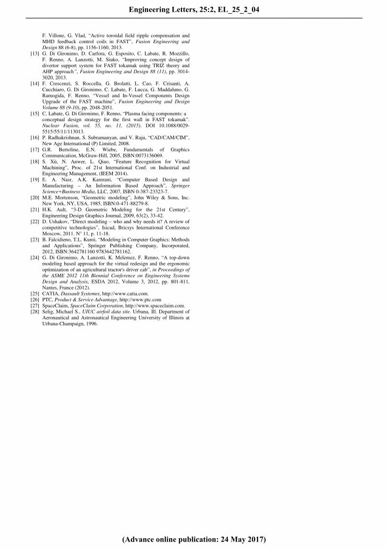
C. Solid Modeling of the Main Landing Gear
The Main Landing Gear (Fig. 9) of the Boeing 737 was
studied. It was simplified by a four parts assembly:
-- Outer Cylinder,
-- Inner Cylinder + axle,
-- Rim,
-- Tyre.
Similarly to the previous case study, it was modeled starting
from a classic approach (Feature-Based Modeling), and then
by means of the Direct Modeling techniques.
Fig. 9. Example of the simplified model of the landing gear of the Boeing
737 aircraft realized and rendered in CAD environment.
The tasks considered for the virtual prototyping are listed in
Fig. 10.
Fig. 10. Tasks defined for the creation of the solid model of the Main
Landing Gear in both the CAD environments.
Each component was realized and then assembled to the
others according to a Bottom-Up approach. Each part was
created starting from a parametrized sketch and by means of
features such as: Pad, Pocket, Hole, Shaft, etc.
Considering the FBM approach for the specific case of
the rim, the solid model was realized with three features
starting from three different sketches: a circle for the pad,
two other circles for the pocket and the last sketch for the
definition of the hole. Instead, in the case of the DM only
two Pull operations, realized simply moving the mouse,
starting from two sketches were needed (Fig. 11).
Engineering Letters, 25:2, EL_25_2_04
(Advance online publication: 24 May 2017)
______________________________________________________________________________________
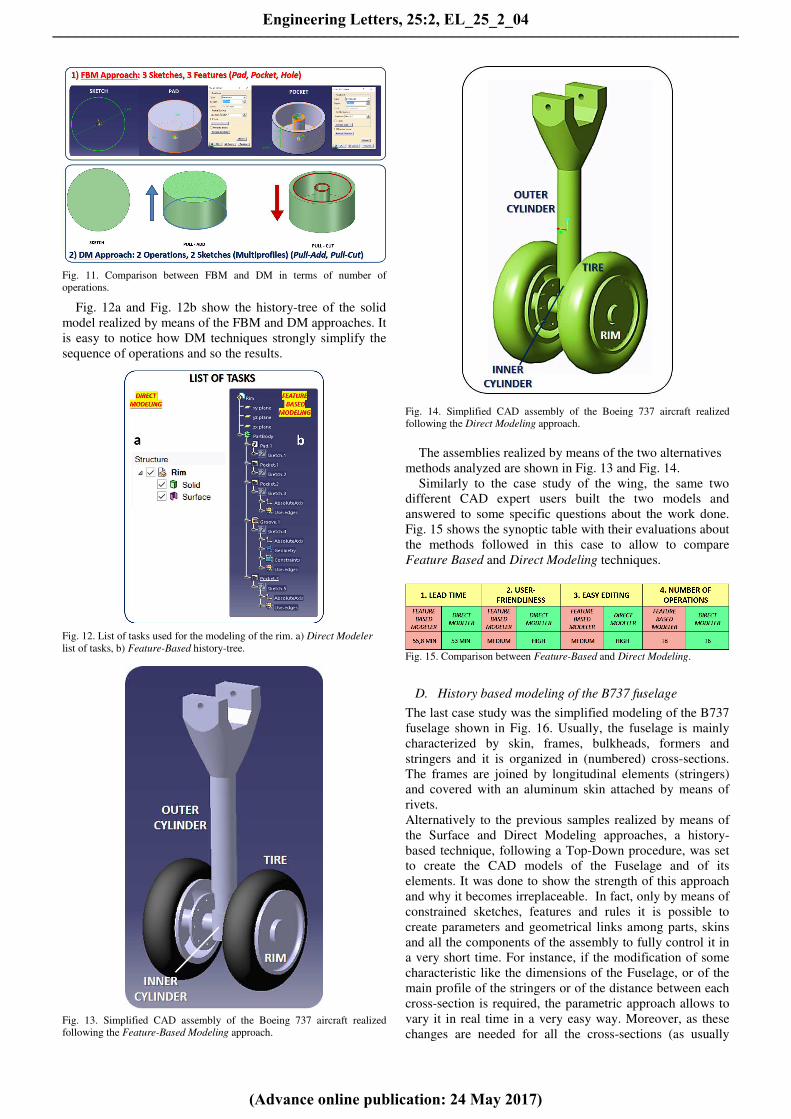
Fig. 11. Comparison between FBM and DM in terms of number of
operations.
Fig. 12a and Fig. 12b show the history-tree of the solid
model realized by means of the FBM and DM approaches. It
is easy to notice how DM techniques strongly simplify the
sequence of operations and so the results.
Fig. 12. List of tasks used for the modeling of the rim. a) Direct Modeler
list of tasks, b) Feature-Based history-tree.
Fig. 13. Simplified CAD assembly of the Boeing 737 aircraft realized
following the Feature-Based Modeling approach.
Fig. 14. Simplified CAD assembly of the Boeing 737 aircraft realized
following the Direct Modeling approach.
The assemblies realized by means of the two alternatives
methods analyzed are shown in Fig. 13 and Fig. 14.
Similarly to the case study of the wing, the same two
different CAD expert users built the two models and
answered to some specific questions about the work done.
Fig. 15 shows the synoptic table with their evaluations about
the methods followed in this case to allow to compare
Feature Based and Direct Modeling techniques.
Fig. 15. Comparison between Feature-Based and Direct Modeling.
D. History based modeling of the B737 fuselage
The last case study was the simplified modeling of the B737
fuselage shown in Fig. 16. Usually, the fuselage is mainly
characterized by skin, frames, bulkheads, formers and
stringers and it is organized in (numbered) cross-sections.
The frames are joined by longitudinal elements (stringers)
and covered with an aluminum skin attached by means of
rivets.
Alternatively to the previous samples realized by means of
the Surface and Direct Modeling approaches, a history-
based technique, following a Top-Down procedure, was set
to create the CAD models of the Fuselage and of its
elements. It was done to show the strength of this approach
and why it becomes irreplaceable. In fact, only by means of
constrained sketches, features and rules it is possible to
create parameters and geometrical links among parts, skins
and all the components of the assembly to fully control it in
a very short time. For instance, if the modification of some
characteristic like the dimensions of the Fuselage, or of the
main profile of the stringers or of the distance between each
cross-section is required, the parametric approach allows to
vary it in real time in a very easy way. Moreover, as these
changes are needed for all the cross-sections (as usually
Engineering Letters, 25:2, EL_25_2_04
(Advance online publication: 24 May 2017)
______________________________________________________________________________________

happens), when the single element is updated all the
modifications are automatically extended to the others
components thanks to the geometrical links created. In fact,
in this case the use of rules, parameters and constraints
makes the final CAD model a powerful and smart tool
robust enough respect to each kind of variation or failure.
Fig. 16. Part of fuselage of the B737, used as case study, modeled starting
from a Top-Down approach.
On the contrary, it is important to note that it is very
difficult (even impossible in most cases) to obtain the same
results counting only on the Direct or Surface Modeling. In
fact, it is not possible to define the rules to fully parametrize
the elements of the fuselage avoiding its upgradeability.
VI. COMPARISON
The several factors previously defined helped to compare
the results obtained by the three cases studied. In particular,
they allowed to identify the pros and the cons of the three
CAD modeling techniques analysed (Feature Based Design,
Surface and Direct Modeling). It was interesting to notice
that the Direct Modeling showed the best results for the
Wing and MLG case studies in terms of a) Lead Time, b)
User Friendliness, c) possibility to properly modify the
geometry and d) number of operations needed to complete
the CAD model. It happened both respect to the Feature
Based approach, and to the Surface Modeling. Furthermore,
it has to be considered that its peculiarities are strongly
convenient for the conceptual design phase when the
freedom to easily modify the models is mandatory for the
designer. Moreover, it was interesting to notice that the
outcomes obtained showed that DM is particularly useful for
the modification of non-parametric prototypes. So, it is
possible to vary solids and surfaces without complex
operations in real time.
On the contrary, the Fuselage case study demonstrated
that the DM is unsuitable when the full geometrical and
dimensional control of the CAD assembly is required. In
other words, in some cases it is very difficult to replace the
benefits of a well “structured” virtual prototype created by
means of a robust Top-Down procedure.
However, although the Feature Based and Surface
Modeling are the standards methods for the CAD modeling
of complex prototypes to be used in the aeronautics and in
the automotive fields, the results obtained demonstrated that
the Direct Modeling can have a very interesting future
among the Geometric Modeling techniques and could be
very useful in industrial field too.
VII. CONCLUSION
In this paper a comparison among Feature Based, Surface
and Direct Modeling was presented. Typically, in the
aeronautic field, there is a massive use of Surface and
Feature Based Modeling for the design and the virtual
prototyping of components as panels, skins, engines, gears,
and so on. For this reason, an aeronautic perspective was
considered setting a comparison between the results
obtained by means of the above mentioned three different
CAD techniques for the simplified virtual prototyping of the
Wing, the Main Landing Gear and of the Fuselage of a
Boeing 737. Two different CAD expert users realized the
models and answered to some specific questions about the
work done. It allowed to find very interesting and hard-to-
beat results in terms of Lead Time, User Friendliness,
possibility to properly modify the geometry and number of
operations needed to complete the CAD model. So, it is
possible to think that in all likelihood, in the nearest future,
the new Direct Modeling approach will represent the
powerful evolution and improvement of the most common
current CAD techniques.
ACKNOWLEDGMENT
The author deeply thanks Eng. Salvatore Iorio and Prof.
Stefano Papa for their technical support.
REFERENCES
[1] S.H. Choi and H.H. Cheung, “Virtual Prototyping for Rapid Product
Development”, in Modeling and Simulation in Engineering, Prof.
Catalin Alexandru (Ed.), InTech, 2012, DOI: 10.5772/25955.
[2] J. Cecil, A. Kanchanapiboon, “Virtual engineering approaches in
product and process design”, in The International Journal of
Advanced Manufacturing Technology, 2007, 31 (9): 846-856.
[3] F. Renno, and S. Papa, "Direct Modeling Approach to Improve
Virtual Prototyping and FEM Analyses of Bicycle Frames,"
Engineering Letters, vol. 23, no. 4, pp333-341, 2015.
[4] A. Lanzotti, F. Renno, M. Russo, R. Russo, M. Terzo, “Design and
development of an automotive magnetorheological semi-active
differential”, Mechatronics, vol. 24, no. 5, pp. 426 – 435, 2014.
[5] F. Renno, and M. Terzo, "Close-Range Photogrammetry Approach
for the Virtual Prototyping of an Automotive Magnetorheological
Semi-active Differential", Engineering Letters, vol. 23, no. 3, pp163-
172, 2015.
[6] A. Lanzotti, F. Renno, M. Russo, R. Russo, and M. Terzo, "Virtual
Prototyping of an Automotive Magnetorheological Semi-Active
Differential by means of the Reverse Engineering Techniques",
Engineering Letters, vol. 23, no. 3, pp115-124, 2015.
[7] A. Lanzotti, F. Renno, M. Russo, R. Russo, M. Terzo, “A physical
prototype of an automotive magnetorheological differential”, Lecture
Notes in Engineering and Computer Science: Proceedings of the
World Congress on Engineering 2013, WCE 2013, 3-5 July, 2013,
London, U.K., pp. 2131 – 2135, 2013.
[8] B. Bidanda, P.J., “Virtual Prototyping & Bio Manufacturing in
Medical Applications”, Springer, 2008. ISBN: 978-0-387-33429-5.
[9] A. Raneda, P. Pessi, M. Siuko, H. Handroos, J. Palmer, M. Vilenius,
“Utilization of virtual prototyping in development of CMM”, Fusion
Engineering and Design, 69 (2003), Pages 183-186.
[10] G. Di Gironimo, C. Labate, F. Renno, M. Siuko, A. Lanzotti, F.
Crisanti, “An interactive design approach for nuclear fusion purposes:
remote handling system for FAST divertor”, International Journal on
Interactive Design and Manufacturing, Vol. 8, Issue 1, Pages 55-65,
February 2014.
[11] G. Di Gironimo, C. Labate, F. Renno, G. Brolatti, F. Crescenzi, F.
Crisanti, A. Lanzotti, F. Lucca, “Concept Design of Divertor Remote
Handling System for the FAST Machine”, Fusion Engineering and
Design, Vol. 88, Issue 9-10, pp. 2052-2056, 2013.
[12] G. Ramogida, G. Calabrò, V. Cocilovo, F. Crescenzi, F. Crisanti,
A. Cucchiaro, G. Di Gironimo, R. Fresa, V. Fusco, P. Martin,
S. Mastrostefano, R. Mozzillo, F. Nuzzolese, F. Renno, C. Rita,
Engineering Letters, 25:2, EL_25_2_04
(Advance online publication: 24 May 2017)
______________________________________________________________________________________
F. Villone, G. Vlad, “Active toroidal field ripple compensation and
MHD feedback control coils in FAST”, Fusion Engineering and
Design 88 (6-8), pp. 1156-1160, 2013.
[13] G. Di Gironimo, D. Carfora, G. Esposito, C. Labate, R. Mozzillo,
F. Renno, A. Lanzotti, M. Siuko, “Improving concept design of
divertor support system for FAST tokamak using TRIZ theory and
AHP approach”, Fusion Engineering and Design 88 (11), pp. 3014-
3020, 2013. [14] F. Crescenzi, S. Roccella, G. Brolatti, L. Cao, F. Crisanti, A.
Cucchiaro, G. Di Gironimo, C. Labate, F. Lucca, G. Maddaluno, G.
Ramogida, F. Renno, “Vessel and In-Vessel Components Design
Upgrade of the FAST machine”, Fusion Engineering and Design
Volume 88 (9-10), pp. 2048-2051.
[15] C. Labate, G. Di Gironimo, F. Renno, “Plasma facing components: a
conceptual design strategy for the first wall in FAST tokamak”.
Nuclear Fusion, vol. 55, no. 11, (2015). DOI 10.1088/0029-
5515/55/11/113013.
[16] P. Radhakrishnan, S. Subramanyan, and V. Raju, “CAD/CAM/CIM”,
New Age International (P) Limited, 2008.
[17] G.R. Bertoline, E.N. Wiebe, Fundamentals of Graphics
Communication, McGraw-Hill, 2005, ISBN:0073136069.
[18] S. Xù, N. Anwer, L. Qiao, “Feature Recognition for Virtual
Machining”, Proc. of 21st International Conf. on Industrial and
Engineering Management, (IEEM 2014).
[19] E. A. Nasr, A.K. Kamrani, “Computer Based Design and
Manufacturing – An Information Based Approach”, Springer
Science+Business Media, LLC, 2007, ISBN 0-387-23323-7.
[20] M.E. Mortenson, “Geometric modeling”, John Wiley & Sons, Inc.
New York, NY, USA, 1985, ISBN:0-471-88279-8.
[21] H.K. Ault, “3-D Geometric Modeling for the 21st Century”,
Engineering Design Graphics Journal, 2009, 63(2), 33-42.
[22] D. Ushakov, “Direct modeling – who and why needs it? A review of
competitive technologies”, Isicad, Bricsys International Conference
Moscow, 2011. N° 11, p. 11-18.
[23] B. Falcidieno, T.L. Kunii, “Modeling in Computer Graphics: Methods
and Applications”, Springer Publishing Company, Incorporated,
2012, ISBN:3642781160 9783642781162.
[24] G. Di Gironimo, A. Lanzotti, K. Melemez, F. Renno, “A top-down
modeling based approach for the virtual redesign and the ergonomic
optimization of an agricultural tractor's driver cab”, in Proceedings of
the ASME 2012 11th Biennial Conference on Engineering Systems
Design and Analysis, ESDA 2012, Volume 3, 2012, pp. 801-811,
Nantes, France (2012).
[25] CATIA, Dassault Systemes, http://www.catia.com.
[26] PTC, Product & Service Advantage, http://www.ptc.com
[27] SpaceClaim, SpaceClaim Corporation, http://www.spaceclaim.com.
[28] Selig, Michael S., UIUC airfoil data site. Urbana, Ill. Department of
Aeronautical and Astronautical Engineering University of Illinois at
Urbana-Champaign, 1996.
Engineering Letters, 25:2, EL_25_2_04
(Advance online publication: 24 May 2017)
______________________________________________________________________________________