feather project in jaxa toward future electric aircraft wednesday presentations...
TRANSCRIPT
FEATHER project in JAXA FEATHER project in JAXA FEATHER project in JAXA FEATHER project in JAXA and and and and
toward future electric aircrafttoward future electric aircrafttoward future electric aircrafttoward future electric aircraftAkira Nishizawa
Section leader of emission free aircraft sectionInnovative Aircraft Systems Research Aircraft Systems Research Team
Next Generation Aeronautical Innovation Hub Center
Japan Aerospace Exploration Agency(JAXA)Hiroshi Kobayashi(JAXA) and Hiroshi Fujimoto(The Univ. of Tokyo)
2nd On-Demand Mobility and Emerging Aviation Technology Roadmapping Workshop, 8-9 March 2016 Lockheed Martin Global Vision CenterArlington VA1

Outline1. Future Vision and Issues 2. FEATHER project3. Toward future electric aircraft
2
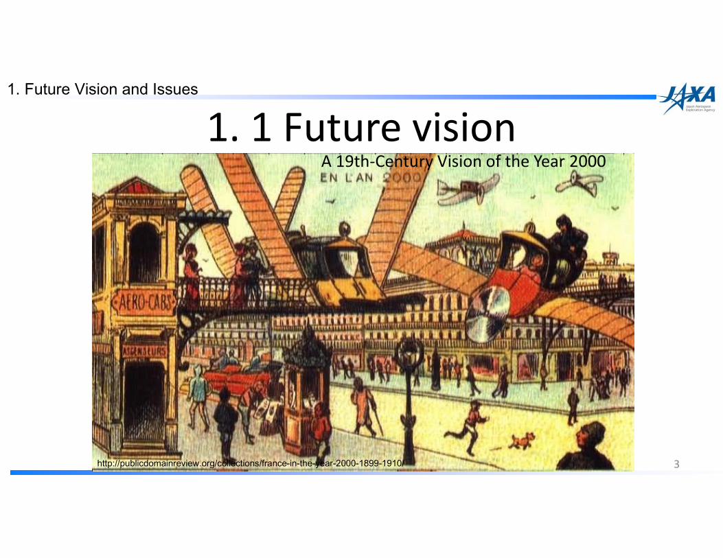
1. 1 Future vision
3http://publicdomainreview.org/collections/france-in-the-year-2000-1899-1910/
A 19th-Century Vision of the Year 2000
1. Future Vision and Issues

1. 2 Problems of Small Aircraft
4
0.00.00.00.0
0.20.20.20.2
0.40.40.40.4
0.60.60.60.6
0.80.80.80.8
1.01.01.01.0
1111 10101010 100100100100 1000100010001000
Tic
ket
fee[U
S$/A
SK
Tic
ket
fee[U
S$/A
SK
Tic
ket
fee[U
S$/A
SK
Tic
ket
fee[U
S$/A
SK]] ]]
No. of seatsNo. of seatsNo. of seatsNo. of seats
Regular feeRegular feeRegular feeRegular fee
Discount feeDiscount feeDiscount feeDiscount fee
0.342.35
10.53 16.57
Higher CostHigher CostHigher CostHigher Cost Lower SafetyLower SafetyLower SafetyLower Safety
Air taxi & Commuter General aviation
Air carrierAir Line
Unit ticket fees for domestic flights (in JAPAN, 2014)
Number of fatal accidents per 1 million flight time (average during 1982-1999 in USA)
The fatal accident rate of small aircraft is about 10X higher 10X higher 10X higher 10X higher than that of large aircraft
Source: NTSB Aviation Accident Database
1. Future Vision and Issues
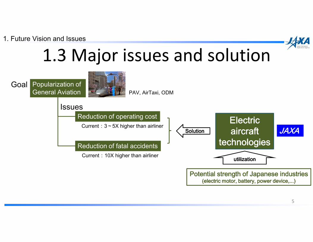
1.3 Major issues and solution
5
Popularization of General AviationPopularization of General Aviation
Reduction of operating costReduction of operating cost
Reduction of fatal accidentsReduction of fatal accidents
Electric Electric Electric Electric aircraft aircraft aircraft aircraft
technologiestechnologiestechnologiestechnologiesSolutionSolutionSolutionSolution
Potential strength of Japanese industriesPotential strength of Japanese industriesPotential strength of Japanese industriesPotential strength of Japanese industries(electric motor, battery, power device,...)(electric motor, battery, power device,...)(electric motor, battery, power device,...)(electric motor, battery, power device,...)
JAXA JAXA JAXA JAXA Current:3~5X higher than airliner
PAV, AirTaxi, ODMGoal
Issues
utilizationutilizationutilizationutilizationCurrent:10X higher than airliner
1. Future Vision and Issues
Outline1. Future Vision and Issues 2. FEATHER project3. Toward future electric aircraft
6

2.1 Outline of FEATHER project2.1 Outline of FEATHER project2.1 Outline of FEATHER project2.1 Outline of FEATHER project
7
Mission�Development of JAXA’s unique electric propulsion systems
2. FEATHER Project
FY2012Design
FY2013Fabrication
FY2014 Integration and flight test
1. Multiplexed motor 2. Regenerative air brake

Reduction gear
①①①①Multiplexed motorMultiplexed motorMultiplexed motorMultiplexed motor ②②②②Pilot interfacePilot interfacePilot interfacePilot interface ③③③③LiLiLiLi----ion batteryion batteryion batteryion battery
Display
Power lever
Electric motor Under wing container
Battery pack
2.2 Overview of the demonstrator2.2 Overview of the demonstrator2.2 Overview of the demonstrator2.2 Overview of the demonstrator
Original aircraft: Diamond aircraft type HK36TTC-ECO
Monitoring unit
8
2. FEATHER Project
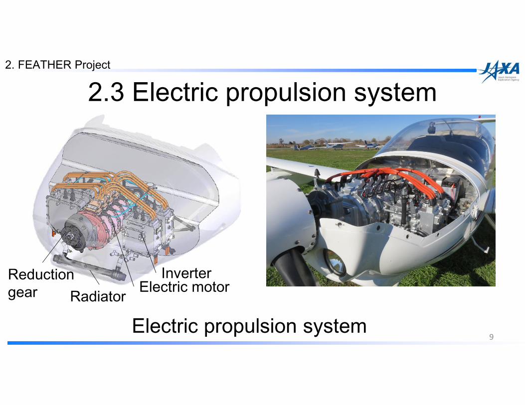
Electric motorInverterReduction
gear Radiator
Electric propulsion system
2.3 Electric propulsion system
9
2. FEATHER Project

SpecificationsSpecificationsSpecificationsSpecificationsWing span 16.33mTake-off weight at the flight test 800kgCrew member 1 personTypes of electric motor and inverter Permanent magnet type synchronous motor
(three-phase) and IGBT inverterMotor control method FOC (Field-oriented control)Maximum total shaft power (at RPM) 60kW (2.5min. at 6586RPM), 63kW(proven at
flight)Type of power source Lithium-ion battery (32 cells in series)System voltage (open circuit at 100%SOC) and Current
128V, 750A
2.4 Specifications
10
2. FEATHER Project

2.5 Multiplexed electric motor system
inverters
232mm220mm
3.75㎏ 1
2
3
4 CharacteristicsCharacteristicsCharacteristicsCharacteristics� Compact� Light weight(2.17kW/kg)� High efficiency(95%)� High strength of structure
11
0
0.5
1
1.5
2
2.5
3
70
75
80
85
90
95
100
30 40 50 60 70 80
Po
we
r d
en
sity
[kW
/kg
]
Eff
icie
ncy
[%]
Maximum output[kW]
+:Efficiency
◆:Power density
Rapid200FC11)
Electric Waiex12)
Antares20E1)
e-Genius13) FEATHER(JAXA)
EV motor(LEAF)
Aircraft piston engine
2. FEATHER Project

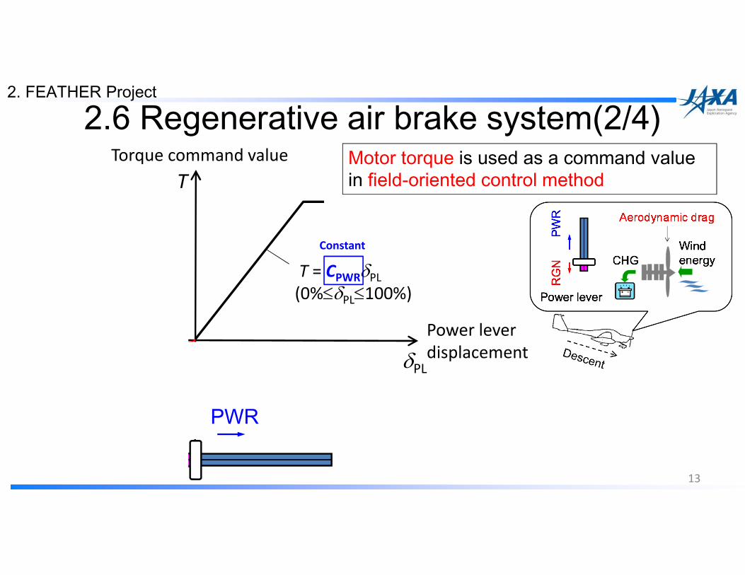
2.6 Regenerative air brake system(1/4)Characteristicfeatures
1. Augmentation of descent rate by only pulling the power lever w/o conventional air brake2. No weight penalty based on the field-oriented control method3. Maximization of the regenerative electricity for variable air speeds
12
Motor Generator
InverterRectifier
Capacitor
DC/DCBattery
Field-oriented control
Motor / Generator
Inverter
Battery
ConventionalPower lever
2. FEATHER Project
13
Power lever
displacement
Torque command value
PWRRGN
2.6 Regenerative air brake system(2/4)Motor torque is used as a command value in field-oriented control methodT
δPL
T = CRGNδPL
(-100%≤δPL≤0%)
T = CPWRδPL
(0%≤δPL≤100%)
ConstantVariable
2. FEATHER Project
14
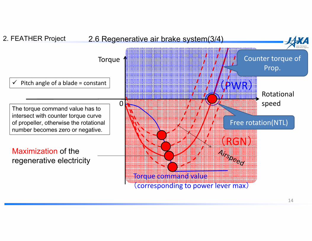
Rotational
speed
Torque
0
2.6 Regenerative air brake system(3/4)
(PWR)
(RGN)
Torque command value
(corresponding to power lever max)
Maximization of the regenerative electricity
� Pitch angle of a blade = constant
2. FEATHER Project
The torque command value has to intersect with counter torque curve of propeller, otherwise the rotational number becomes zero or negative.
Counter torque of
Prop.
Free rotation(NTL)

2.6 Regenerative air brake system(4/4)
Specially designed power lever to facilitate the control of descent rate and regeneration
Block diagram of the regenerative air brake system
Vair is not necessary as the feedback parameter to maximize the regenerative power in this system.
Motor/ Generator Inverter
System control unit
Battery
Target Torque Target Torque Target Torque Target Torque NNNNpppp Power lever
PropellerDisplay
displacement
Pitot tubeVair Regenerative power
15
2. FEATHER Project

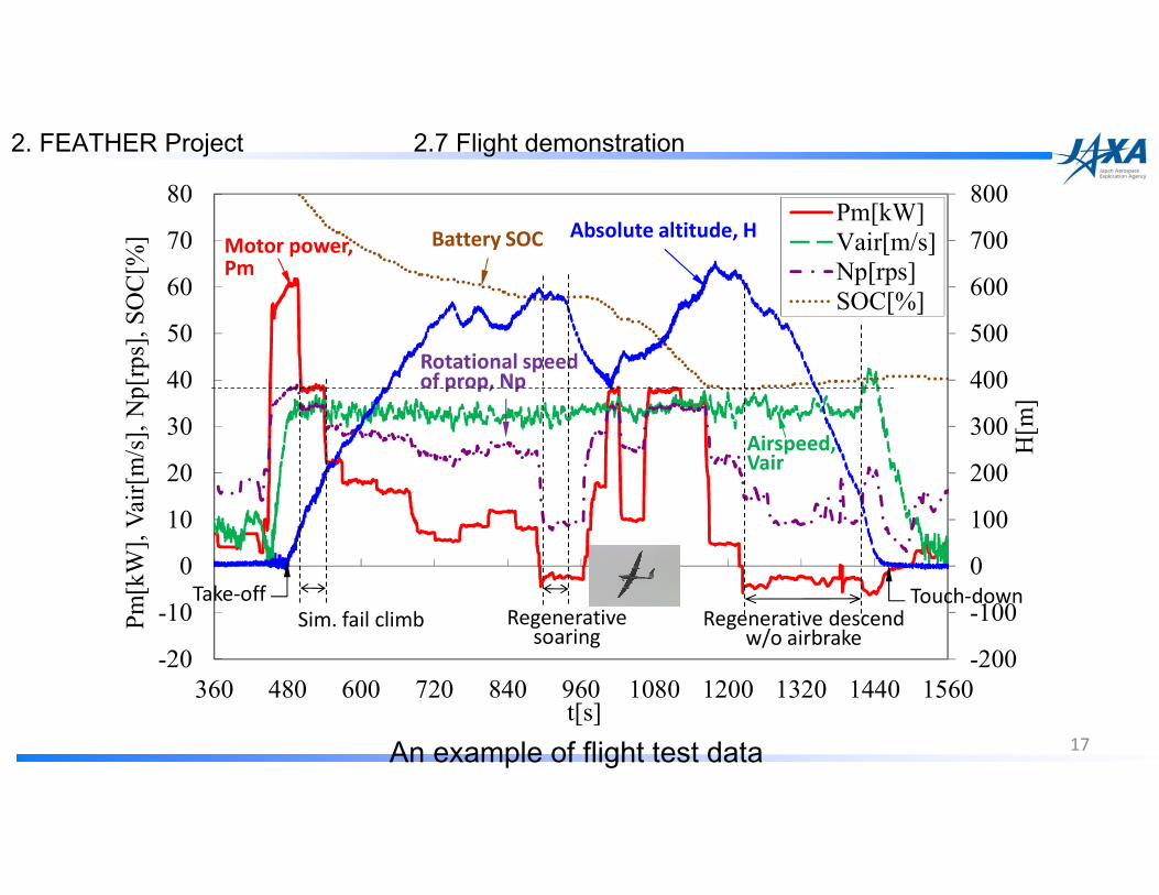
2.7 Flight demonstration
16
2. FEATHER Project
-200
-100
0
100
200
300
400
500
600
700
800
-20
-10
0
10
20
30
40
50
60
70
80
360 480 600 720 840 960 1080 1200 1320 1440 1560
H[m]
Pm[kW], Vair[m/s],Np[rps], SOC[%]
t[s]
Pm[kW]
Vair[m/s]
Np[rps]
SOC[%]
Motor power, Pm
Absolute altitude, H
Airspeed, Vair
Rotational speed of prop, Np
Take-off
Battery SOC
Touch-downSim. fail climb Regenerative
soaring Regenerative descend
w/o airbrake
An example of flight test data 17
2. FEATHER Project 2.7 Flight demonstration
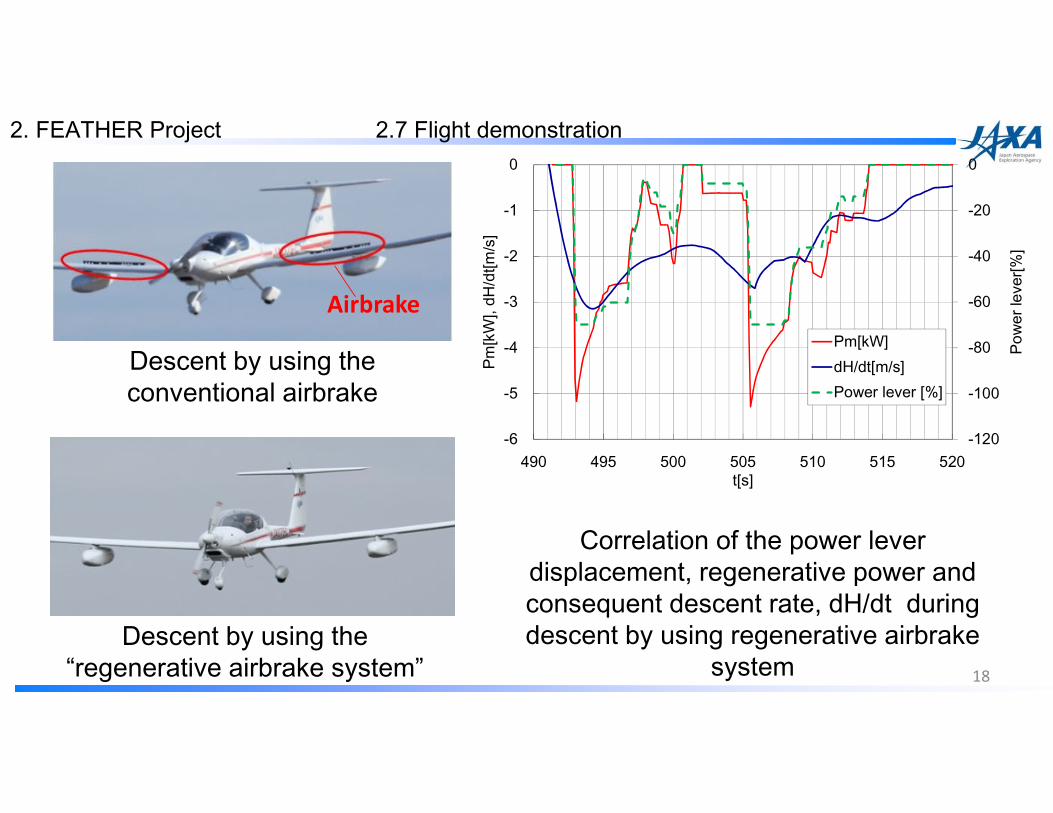
Airbrake
2.7 Flight demonstration
Descent by using the conventional airbrake
Descent by using the “regenerative airbrake system”
-120
-100
-80
-60
-40
-20
0
-6
-5
-4
-3
-2
-1
0
490 495 500 505 510 515 520
Pow
er le
ver[%
]
Pm[k
W],
dH/d
t[m/s
]t[s]
Pm[kW]dH/dt[m/s]Power lever [%]
Correlation of the power lever displacement, regenerative power and consequent descent rate, dH/dt during descent by using regenerative airbrake
system 18
2. FEATHER Project

Outline1. Future Vision and Issues 2. FEATHER project3. Toward future electric aircraft
19
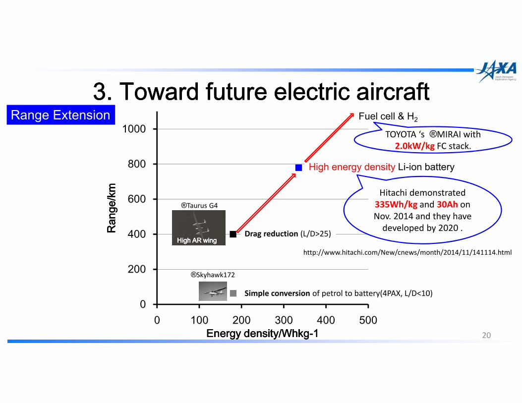
3. Toward 3. Toward 3. Toward 3. Toward future electric aircraftfuture electric aircraftfuture electric aircraftfuture electric aircraft
20
0
200
400
600
800
1000
0 100 200 300 400 500
Ran
ge/k
mR
ange
/km
Ran
ge/k
mR
ange
/km
Energy density/WhkgEnergy density/WhkgEnergy density/WhkgEnergy density/Whkg----1111
Drag reduction (L/D>25)
Simple conversion of petrol to battery(4PAX, L/D<10)
High AR wingHigh AR wingHigh AR wingHigh AR wing
High energy density Li-ion battery
http://www.hitachi.com/New/cnews/month/2014/11/141114.html
Fuel cell & H2Range Extension
Hitachi demonstrated
335Wh/kg and 30Ah on
Nov. 2014 and they have
developed by 2020 .
®Skyhawk172
®Taurus G4
TOYOTA ‘s ®MIRAI with
2.0kW/kg FC stack.

3. Toward 3. Toward 3. Toward 3. Toward future electric aircraftfuture electric aircraftfuture electric aircraftfuture electric aircraft
21
Automatization 1. Electric propulsion system have a high affinity for automatization.
2. Electric motor have a high response performance.
3. Electric motor can be flexibly arranged on a wing or a fuselage.
Power by wire Key technology
ComputerComputerComputerComputerInverterInverterInverterInverter
MotorMotorMotorMotor SensorsSensorsSensorsSensors
Sensing ActuatorSensing ActuatorSensing ActuatorSensing Actuator Control AlgorithmControl AlgorithmControl AlgorithmControl Algorithm Alternative S&CAlternative S&CAlternative S&CAlternative S&C
Collaborative work

22
Thank youThank youThank youThank you
http://www.aero.jaxa.jp/eng/research/frontier/feather/
http://hflab.k.u-tokyo.ac.jp/index.html

23
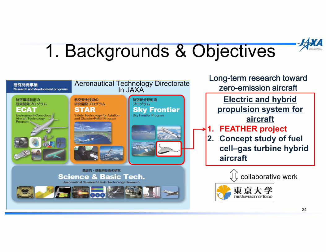
1. Backgrounds & Objectives
24
Electric and hybrid
propulsion system for
aircraft
1. FEATHER project
2. Concept study of fuel
cell–gas turbine hybrid
aircraft
LongLongLongLong----term term term term research toward research toward research toward research toward zerozerozerozero----emission aircraft emission aircraft emission aircraft emission aircraft
collaborative work
Aeronautical Technology DirectorateIn JAXA
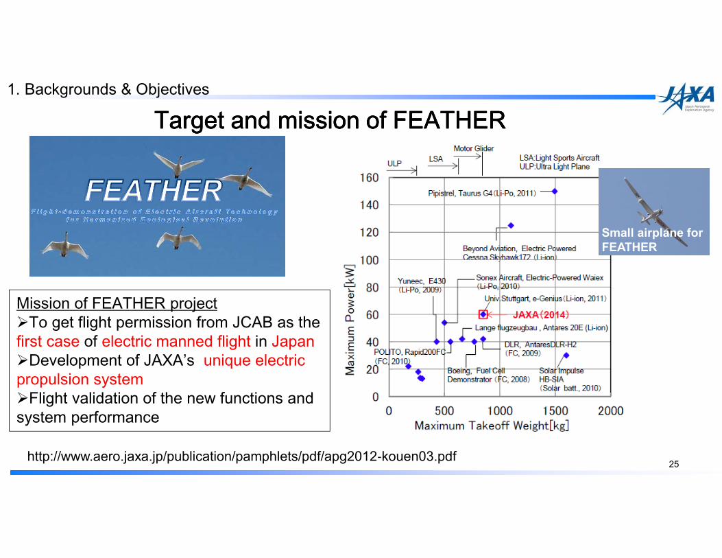
Target and mission of FEATHERTarget and mission of FEATHERTarget and mission of FEATHERTarget and mission of FEATHER
http://www.aero.jaxa.jp/publication/pamphlets/pdf/apg2012‐kouen03.pdf25
Small airplane for
FEATHER
Mission of FEATHER project�To get flight permission from JCAB as the first case of electric manned flight in Japan �Development of JAXA’s unique electric propulsion system�Flight validation of the new functions and system performance
1. Backgrounds & Objectives
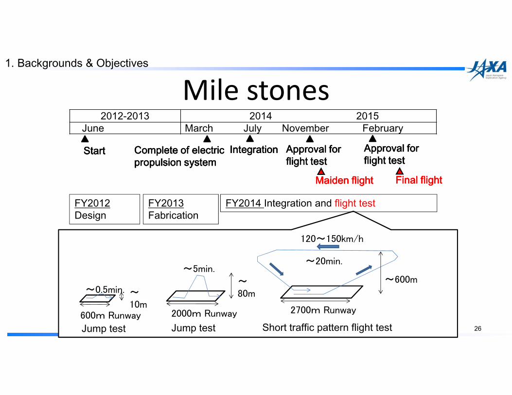
Mile stones
26
2012-2013 2014 2015June March July November February
StartStartStartStart IntegrationIntegrationIntegrationIntegration Approval for Approval for Approval for Approval for flight testflight testflight testflight test
Maiden flightMaiden flightMaiden flightMaiden flight
Complete of electric Complete of electric Complete of electric Complete of electric propulsion systempropulsion systempropulsion systempropulsion system
FY2012Design
FY2013Fabrication
FY2014 Integration and flight test
Final flightFinal flightFinal flightFinal flight
600m Runway
~10m
~0.5min.
Jump test
2700m Runway
120~150km/h
~600m
~20min.
Short traffic pattern flight testJump test2000m Runway
~80m
~5min.
Approval for Approval for Approval for Approval for flight testflight testflight testflight test
1. Backgrounds & Objectives

A) Electric motor-glider system
A1-1)Driving system
Multiplexed motorInverter
Radiator & PumpReduction gear
Propeller
A2) Measurement system
A3) Airframe system
A4) Charging system
Li-ion battery
A1-2)Power source
A1-3)Pilot interface
A1-4)Management system
DisplayPower lever
System control unit
A1) Electric propulsion system
2. Systems
System configuration
Electric motor-glider system(Flight demonstrator)
27
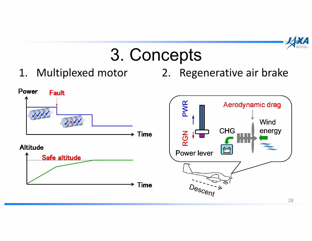
3. Concepts1. Multiplexed motor 2. Regenerative air brake
28

3.1 Multiplexed electric motor system(1/3)Our motivations
1. Avoidance of “loss of engine power” for single piston engine aircraft.2. Redundancy of electric motors.
Other researches
1. Distributed motors and fans for VTOL (Alex M. Stoll et al. of Joby Aviation, 14th AIAA Aviation Technology, Integration and Operations Conference 2014, AIAA2014-2407)
2. Electric Propulsion for Vertical Flight (Michael Ricci of LaunchPoint Technologies; AHS Transformative Vertical Flight Workshop 2014, Arlington, VA )
Our selection of approach
Putting multiplexed motor on a propeller shaft
3. Concepts
29
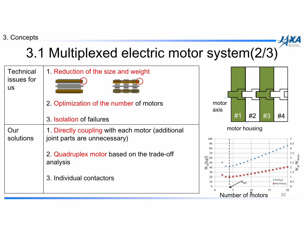
Technical issues for us
1. Reduction of the size and weight
2. Optimization of the number of motors
3. Isolation of failuresOur solutions
1. Directly coupling with each motor (additionaljoint parts are unnecessary)
2. Quadruplex motor based on the trade-off analysis
3. Individual contactors0
0.5
1
1.5
2
2.5
3
3.5
4
4.5
5
0
10
20
30
40
50
60
70
80
90
100
0 5 10 15 20
Wth/W
thmin
Wth[kgf]
n
Wth[kgf]
Wth/Wthminnopt
#1 #2 #3 #4
motor housing
motor axis
3.1 Multiplexed electric motor system(2/3)3. Concepts
30Number of motors

3.2 Regenerative air brake system(1/5)Our motivations
1. Elimination of conventional systems by multifunctionality of electric motor.2. Regeneration of electricity by electric motor.
Other researches
1. Feasibility study of regenerative soaring (J.Philip Barnes, Perican Aero Group, SAE Tech. Paper 2006-01-2422, 2006)2. WATTsUP can recuperate 13% of energy on every approach and reduce the field length of landing(Pipistrel, Aircraft News,31 Mar 2015)
Our selection of approach
1. Utilization of aerodynamic drag on the prop. due to regeneration2. Simultaneously harvesting a certain amount of energy
3. Concepts
31
Regenerative air brake system

2.6 Regenerative air brake system(1/4)Technical issues for us
1. Simplify the control of descent rate2. Avoidance of weight penalty and hardware complexity3. Maximization of the regenerative electricity
Our solutions 1. Augmentation of descent rate by pulling the power lever2. The simplest system configuration based on the field-oriented control method3. Formulation of control algorithm based on the aerodynamic features
32
Motor Generator
InverterRectifier
Capacitor
DC/DCBattery
Field-oriented control
Motor / Generator
Inverter
Battery
ConventionalPower lever
2. FEATHER Project

33
Power lever
displacement
Torque command value
PWRRGN
3.2 Regenerative air brake system(3/5)3. Concepts
Motor torque is used as a command value in field-oriented control method
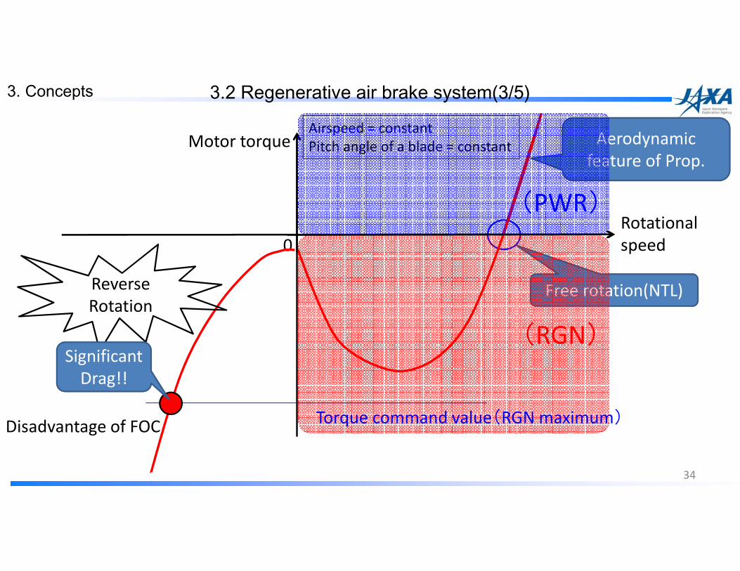
34
Rotational
speed
Motor torque Aerodynamic
feature of Prop.
0
Airspeed = constant
Pitch angle of a blade = constant
3.2 Regenerative air brake system(3/5)3. Concepts
Free rotation(NTL)
(PWR)
(RGN)
Reverse
Rotation
Torque command value(RGN maximum)
Significant
Drag!!
Disadvantage of FOC

35
Rotational
speed
Motor torque Aerodynamic
feature of Prop.
0
Airspeed = constant
Pitch angle of a blade = constant
3.2 Regenerative air brake system(3/5)3. Concepts
Free rotation(NTL)
(PWR)
(RGN)
Torque command value(RGN maximum)
opportunity loss

36
Rotational
speed
Motor torque Aerodynamic
feature of Prop.
0
Airspeed = constant
Pitch angle of a blade = constant
3.2 Regenerative air brake system(3/5)3. Concepts
Free rotation(NTL)
(PWR)
(RGN)
Torque command value(RGN maximum)
Maximization of the regenerative electricity
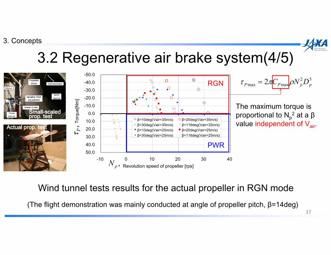
-50.0-40.0-30.0-20.0-10.0
0.010.020.030.040.050.0
-10 0 10 20 30 40
Torq
ue[N
m]
Revolution speed of propeller [rps]
β=10deg(Vair=35m/s) β=20deg(Vair=35m/s)β=30deg(Vair=35m/s) β=116deg(Vair=35m/s)β=10deg(Vair=25m/s) β=20deg(Vair=25m/s)β=30deg(Vair=25m/s) β=116deg(Vair=25m/s)
3.2 Regenerative air brake system(4/5)
Wind tunnel tests results for the actual propeller in RGN mode(The flight demonstration was mainly conducted at angle of propeller pitch, β=14deg)
PWR
RGN
SmallSmallSmallSmall----scaled scaled scaled scaled prop. testprop. testprop. testprop. test
Actual prop. testActual prop. testActual prop. testActual prop. test
52
maxmax 2 ppPP DNC ρπτ =
The maximum torque is proportional to Np
2 at a βvalue independent of Vair.
,pN
3. Concepts
37

35.38
35.382
35.384
35.386
35.388
35.39
35.392
35.394
35.396
35.398
35.4
136.845 136.85 136.855 136.86 136.865 136.87 136.875 136.88 136.885 136.89 136.895
Lat[deg]
Long[deg]1km
Typical example of the short traffic path
Tower
Runway
4. Flight demonstration
38

-200
-100
0
100
200
300
400
500
600
700
800
-20
-10
0
10
20
30
40
50
60
70
80
360 480 600 720 840 960 1080 1200 1320 1440 1560
H[m]
Pm[kW], Vair[m/s],Np[rps], SOC[%]
t[s]
Pm[kW]
Vair[m/s]
Np[rps]
SOC[%]
Motor power, Pm
Absolute altitude, H
Airspeed, Vair
Rotational speed of prop, Np
Take-off
Battery SOC
Touch-downSim. fail climb Regenerative
soaring Regenerative descend
w/o airbrake
An example of flight test data 39
2. FEATHER Project 2.7 Flight demonstration

5. SummaryWe have succeeded in flight demonstration as follows:
1. Avoidance Avoidance Avoidance Avoidance of complete of complete of complete of complete power power power power loss loss loss loss in engine failure during climb by using the multiplexed electric motor2. RegenerationRegenerationRegenerationRegeneration of of of of electricity electricity electricity electricity about 8% of maximum motor output during descent3. Control of descent rate by the proposed regenerative regenerative regenerative regenerative airbrake systemairbrake systemairbrake systemairbrake system without conventional airbrake4. Continuous “regenerative soaringregenerative soaringregenerative soaringregenerative soaring” free from descent in thermal condition
Acknowledgement: The wind tunnel test in this research was partly supported by the Ministry of Education, Culture, Sports, Science, and Technology grant (Basic Research A, number: 26249061). 40

41
∆∆∆∆Np ∆∆∆∆VS ∆∆∆∆L
� Torque
� Thrust
� Airspeed