feasibility study of bst for truck application · feasibility study of bst for truck application...
TRANSCRIPT

Feasibility study of BST for truck application
M.C.J. Baggen 484278
1 july 2004

1

Contents
1 Introduction 3
2 Retarders in general 42.1 Introduction to the use of retarders . . . . . . . . . . . . . . . . . . . . . . . . 42.2 Hydrodynamic retarder . . . . . . . . . . . . . . . . . . . . . . . . . . . . . . 5
2.2.1 Working principle . . . . . . . . . . . . . . . . . . . . . . . . . . . . . 52.2.2 Cooling . . . . . . . . . . . . . . . . . . . . . . . . . . . . . . . . . . . 62.2.3 Power losses . . . . . . . . . . . . . . . . . . . . . . . . . . . . . . . . . 72.2.4 Control of the retarder . . . . . . . . . . . . . . . . . . . . . . . . . . . 7
2.3 Electrical retarders . . . . . . . . . . . . . . . . . . . . . . . . . . . . . . . . . 72.3.1 Working principle . . . . . . . . . . . . . . . . . . . . . . . . . . . . . 72.3.2 Cooling . . . . . . . . . . . . . . . . . . . . . . . . . . . . . . . . . . . 92.3.3 Control of the retarder . . . . . . . . . . . . . . . . . . . . . . . . . . . 102.3.4 Power losses . . . . . . . . . . . . . . . . . . . . . . . . . . . . . . . . . 10
2.4 Comparison . . . . . . . . . . . . . . . . . . . . . . . . . . . . . . . . . . . . . 102.5 The ZF intarder . . . . . . . . . . . . . . . . . . . . . . . . . . . . . . . . . . 12
3 Specifications of the truck and transmission 143.1 Daf XF 95 . . . . . . . . . . . . . . . . . . . . . . . . . . . . . . . . . . . . . . 143.2 ZF Astronic transmission . . . . . . . . . . . . . . . . . . . . . . . . . . . . . 17
4 Design of the Brake Shift System 204.1 BST concept explanation . . . . . . . . . . . . . . . . . . . . . . . . . . . . . 204.2 Modeling of the system . . . . . . . . . . . . . . . . . . . . . . . . . . . . . . 214.3 Integration in the transmission . . . . . . . . . . . . . . . . . . . . . . . . . . 23
4.3.1 Changing the splitter group . . . . . . . . . . . . . . . . . . . . . . . . 244.3.2 A separate shaft with shiftable rGN . . . . . . . . . . . . . . . . . . . 27
4.4 Required torques and powers . . . . . . . . . . . . . . . . . . . . . . . . . . . 294.4.1 Torques . . . . . . . . . . . . . . . . . . . . . . . . . . . . . . . . . . . 294.4.2 Powers . . . . . . . . . . . . . . . . . . . . . . . . . . . . . . . . . . . . 31
4.5 Performance expectations . . . . . . . . . . . . . . . . . . . . . . . . . . . . . 32
5 Conclusions 33
2

Chapter 1
Introduction
In this report the feasibility of the use of a retarder for a Brake Shift Transmission (BST) ina truck is discussed. The reference transmission is a ZF AStronic twelve speed transmissionwith intarder. The BST concept enables the vehicle of providing the wheels with torqueduring shift moments. This improves the gear shift quality. In conventional manual, and inautomated manual transmissions as the AStronic the torque is interrupted during shifting.The BST system makes use of a brake and a planetary gear to handle the powerflow. Becausea lot of trucks already have a retarder integrated in the transmission, the use of the retarderas brake in the BST application can be interesting. Because of the high powers involved, aretarder is ideal for supporting high brake forces. A comparison is made between differentretarders in chapter 2. The specifications of the truck and transmission are studied in chapter3. In chapter 4 a model of the system is made and the model is optimized for different criteria.Also suggestions are made for topologies of the system into the Astronic gearbox.
3

Chapter 2
Retarders in general
2.1 Introduction to the use of retarders
Retarders are used for generating a braking torque opposite to a rotational motion to slow avehicle down. They are additional to the conventional friction brakes. Conventional frictionbrakes are capable of generating very high braking torques and absorbing energy at highrates for short periods. The disadvantage of these brakes is that they wear out because of thefriction. Another disadvantage is the risk of fading. When a heavy truck is running downhill,large braking power is needed for a long period of time to stop the vehicle. Conventionalfriction brakes like drum brakes or disk brakes only have a limited amount of heat capacityand heat dissipation. To meet the braking requirement and to reduce wear in conventionalbrakes retarders are used.Retarders are based on electro-magnetic eddy current braking or hydrodynamic braking. Inthis paper the eddy current brake and the hydrodynamic brake will be discussed. Becausethe brake has to be used in the BST concept engine brakes are not discussed.The retarders can be positioned at different locations of the drive train. Retarders locatedat the engine side of the gearbox are called primary retarders and retarders at the driveshaft side of the gearbox are called secondary retarders. Primary retarders deliver a geardependent braking torque which increases as transmission ratios become higher, and gearslower. They can therefore generate higher braking torques at low speeds. Disadvantages arepossible engine stall, additional loads on the transmission and the interruption of brakingpower flow during shifting. Primary retarders are often integrated in to the transmission andcombined with the torque convertor. The braking torque of secondary retarders is only afunction of the vehicle speed. High braking torques are available for a wide velocity range.At high speeds large power can be consumed. To increase the braking torques at lower speedan additional step up gear can be used to increase the velocity of the retarder. This can alsodecrease the size of the retarder. A ratio of 1:2 is common.The braking power of the retarder is controlled by hand at the steering column. Also au-tomatic controls are available that are actuated by the braking pedal. The system can beintegrated with ABS systems and can even be used as a ’cruise control’ for downhill driving.
4

Figure 2.1: secondary and primary retarders
Figure 2.2: Structure of a hydrodynamic retarder
2.2 Hydrodynamic retarder
2.2.1 Working principle
The concept to use fluid as a working medium to oppose rotary motion and absorb energyis used for a long time. Froude invented a dynamometer in 1877 to measure torques. Thehydrodynamic retarder consists of a rotor connected to the rotating shaft and a stator fixedto the retarder housing. The rotor is turning and generates a centrifugal force on the fluid.This forces the fluid to travel in a radial outwards flow. At the same time the fluid has atangential speed due to the rotation of the rotor. When the fluid is centrifuged outwards into the cavities of the stator (which stands still), the tangential speed is abruptly stopped, andthe fluid flows back to the center of the turbine to enter the rotor again. This arresting andaccelerating of the tangential velocity component of the fluid velocity and the momentum ofthe flow generates a braking torque. Because there is no work produced all energy will beturned in to heat by heating up the oil. The relationship of the retarder torque T to thediameter D, the speed ω, the oil density r and the performance λ is shown in the generalformula 2.1
Tr = λρω2D5 (2.1)
The torque is dependent on ω2 and D5. D is an important factor. The performance coefficient
5

Figure 2.3: Schematic hydrodynamic retarder
λ normally is a function of the speed ratio ν = ωsωr
. In this case the speed ratio obviously iszero because the stator stands still. The coefficient λ is now a function of the rotor speed, theblade angle and the fill level. Of course also ρ is a function of the fill level because the densityof air differs a lot from the density of the fluid, generally oil. The retarder is controlled bychanging the amount of liquid in the circuit. The retarder fill level controls the braking torqueof the retarder. Of course the retarder can produce no braking torque when the vehicle is atrest. The retarder fill level is controlled by pressure. The oil is retained in the retarder by thiscontrol pressure. The pressure on the retarder outlet is approximately proportional to theretarder torque. Because the rotor works as a pump it builds up pressure and the fluid wantsto escape. A high value for the fluid density ρ would be desirable to generate high torques.Considering figure 2.2 it is clear that the curve for 100% fill coincides with the equation forthe retarder torque. For certain higher values of ω the generated torque no longer followsthis curve. The reason for this is that the pressure at the retarder outlet is limited. Whenthe speed increases to a certain value the pressure generated bij the retarder is too high andthere will no longer be a 100% fill.
2.2.2 Cooling
The continuous braking power is limited by the cooling capacity of the system rather thanby the retarder itself. Often the cooling system is shared with the engine cooling system.During driving downhill the engine produces less power and needs less cooling capacity. Thiscan be counteracted by an exhaust brake which generates heat in the engine. This heat alsohas to be cooled by the engine cooling system. The retarder is sometimes integrated into thetransmission and shares oil and oil pump with the transmission. This decreases the weightof the retarder. Cooling capacity is currently limited to around 300 kW. For short periodsof time higher braking powers can be developed. To get additional cooling also liquid to airheat exchangers can be installed. The temperature rise across the retarder can be calculatedas from the following equation.
Qf =P
Cpρ∆T(2.2)
Where Qf represents the fluid flow through the retarder, P the power consumed, Cp thespecific heat of the fluid and ∆T the temperature rise across the retarder. A high specific
6

heat is of course desirable. Water has a high specific heat and a high density. Disadvantageis that water has a low boiling temperature, and a bad corrosion resistance and lubrication.
2.2.3 Power losses
To control the retarder an oil booster has to be controlled. Also a hydraulic pump suppliesoil pressure. Fan losses occur when the retarder is not being used but still generates a smallamount of torque. This is the result of the air circulating between the rotor and stator. Thereare devises to reduce these losses by engaging slides between rotor and stator.
2.2.4 Control of the retarder
The braking power is controlled by the oil fill level of the retarder. As mentioned before theretarder torque is approximately proportional to the outlet pressure of the retarder. This isof course for the area in figure 2.2 where the retarder is not filled 100%. Often a cylinderfilled with oil and pressurized with air is used to regulate the pressure at the discharge portof the rotor (impellor). In this way the retarder can be filled fast to ensure a short responsetime.
2.3 Electrical retarders
2.3.1 Working principle
The electric retarder can develop negative powers reaching 500 kW during short times. Thisbraking power can be enough to satisfy all braking requirements even without the use offriction brakes. It is estimated that an electrical retarder can deliver 80% of the duty whichotherwise would have been delivered by the service brakes. These advantages are equal to thehydrokinetic retarder.The principle of the electric retarder is based on the creation of eddy currents in a metal discrotating between electro-magnets, which setup a force opposing the rotation of the disk.As long as the electro-magnets are not energized, the disk will rotate freely. When theelectro-magnets are energized, the rotation of the disk is retarded and the energy absorbed istransferred into heat. The electro - magnets are powered with current from the batteries ofthe vehicle. The braking torque varies proportional to the value of the current through thecoils of the electro magnets. In this way the torque is easy to control by changing the current.The eddy current electric retarder for vehicles is often mounted directly on the driveshaft.The reason for this is that the cooling fins can blow the air freely and spread the heat that isgenerated.The electric retarder is relatively simple to produce yet it uses a complex electro-magneticphenomena. The calculations made of these systems are often empirical or done with finiteelement programs.The simple principle of why these eddy-currents work as a brake will be explained. If a currentflows through a conductor, a magnetic field is produced with an intensity proportional to thecurrent. In a coil for example the magnetic intensity equals:
Hm =Ni
lm[A/M ] (2.3)
7
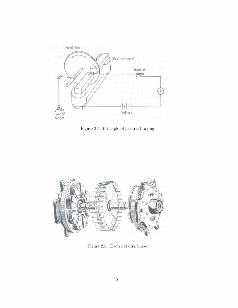
Figure 2.4: Principle of electric braking
Figure 2.5: Electrical disk brake
8
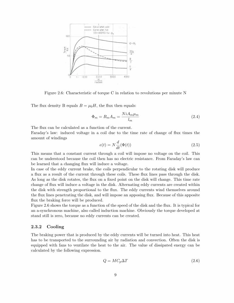
Figure 2.6: Characteristic of torque C in relation to revolutions per minute N
The flux density B equals B = µ0H, the flux then equals:
Φm = BmAm =NiAmµm
lm(2.4)
The flux can be calculated as a function of the current.Faraday’s law: induced voltage in a coil due to the time rate of change of flux times theamount of windings
e(t) = Nd
dt(Φ(t)) (2.5)
This means that a constant current through a coil will impose no voltage on the coil. Thiscan be understood because the coil then has no electric resistance. From Faraday’s law canbe learned that a changing flux will induce a voltage.In case of the eddy current brake, the coils perpendicular to the rotating disk will producea flux as a result of the current through these coils. These flux lines pass through the disk.As long as the disk rotates, the flux on a fixed point on the disk will change. This time ratechange of flux will induce a voltage in the disk. Alternating eddy currents are created withinthe disk with strength proportional to the flux. The eddy currents wind themselves aroundthe flux lines penetrating the disk, and will impose an apposing flux. Because of this appositeflux the braking force will be produced.Figure 2.6 shows the torque as a function of the speed of the disk and the flux. It is typical foran a-synchronous machine, also called induction machine. Obviously the torque developed atstand still is zero, because no eddy currents can be created.
2.3.2 Cooling
The braking power that is produced by the eddy currents will be turned into heat. This heathas to be transported to the surrounding air by radiation and convection. Often the disk isequipped with fans to ventilate the heat to the air. The value of dissipated energy can becalculated by the following expression.
Q = MCp∆T (2.6)
9

The disc can reach temperatures of 400 degrees Celsius. Thermal stability will be achievedbecause the mass of air passing through the fan M will increase at higher speed, and thecooling capacity will increase with higher temperature differences. The torque will decreasewith a rising temperature of the disk to a value that is half of the torque generated by a colddisk. The electric resistance increases and the magnetic permeability decreases at a risingtemperature.A disadvantage of this electric retarder is that the heat produced in the disk has to be cooledby the centrifugal fan on the disk. This means that it is difficult to mount this retarder in aclosed environment near to the engine and gearbox. Maybe solutions can be found to solvethis problem. One could think of transporting the hot air away from the retarder by an airchannel fitted with additional fans. Water could also be used to cool the disk and transportthe heat away, but the flow and cooling capacity should be great enough to prevent the waterof boiling. Another option could be to transport the power electrical to another place. Thiswould mean that another machine would have to be designed. An a-synchronous electricalgenerator would be used to generate the braking currents. The currents are not used to heatup the disk, but are transported to a heat exchanger through electrical wires. There aresome disadvantages of this system. A-synchronic machines of this size fitted with coils onboth stator and rotor would have a lot of weight and are expensive. Also the problem arisesof transporting these large powers though electrical wires to a heat exchanger outside thevehicle. High-speed machines can be used to generate high voltages around 1000 Volts, buteven then 400 Amperes are needed to transport the power of 400 kW. An average power linecan only handle 10A/mm2. This means very heavy power lines would be needed.
2.3.3 Control of the retarder
Braking power is controlled by the amount of current through the coils. This is done by a setof relay boxes. The power is retracted from the vehicle battery. A cut-off system is coupledto prevent activation of the retarder at very low vehicle speeds when the driver presses thebrake pedal.
2.3.4 Power losses
The power losses when the retarder is not in use (fan and bearing losses) are relatively small.When the retarder is in use it will need power for the battery to power the coils. Themaximum power use is around 3.5 kW, but the average power consumption lies much lower.The average power consumption lies beneath 0.25 and 0.35 kW. A normal truck battery isable of providing this power.
2.4 Comparison
The electrical and hydraulic retarders are compared at a few criteria shown in table 2.1.The best advantage of the hydraulic retarder is the possibility to be integrated into thetransmission. This is ideal for the combination with the BST system which also has to beintergrated into the transmission. Electrical retarders are often fitted at the driveshaft to tocool with surrounding air. The controllability has to meet certain requirements to use thesystem for BST purpose.
10

Criteria Electrical retarder Hydraulic retarderCost Relatively cheap, sold sepa-
rateMore expensive, but oftenavailable as option
Weight 200 - 300 kg Dependent on designInstallation Easy because of simple design;
Not very big (350mm) diame-ter; Installed at driveshaft
Often already installed intransmission with shared en-gine cooling system
Power Around 500 kW Around 500 kWTorque High torques (3000 Nm) al-
ready from 1000 rpm, Max-imum torque can drop athigher speed
High maximum torques (1500Nm) starting at 750 rpm
Controllability Good by applying current tothe system
Reasonable by pressurizingthe system oil is forced to therotor
Power losses Almost zero (bearing losses);Small energization losses
Small fan losses from air tur-bulence in the rotor
Speed Around 4000 rpm Around 3500 rpmCooling Forced air cooling (not in
closed environment)Shared with engine cooling(engine overheating has to beprevented)
Table 2.1: Comparison on different criteria
11

Figure 2.7: ZF Intarder with braking graph. The vehicle speed is proportional to the retarderspeed ωr with rFD = 3.4 and step up ratio 2. The torque is measured at the driveshaft whichis twice the retarder torque.
2.5 The ZF intarder
The ZF intarder is a secondary hydrodynamic retarder consistent of a rotor with step upgear and stator integrated into a ZF AS-tronic transmission. The retarder system consistsof the intarder, a heat exchanger and an electronic control unit. It is directly connected tothe driveshaft with a step up gear as can be seen in figure 2.7. Therefor the braking torquecan be shown as a function of the vehicle speed also in figure 2.7. With a maximum brakingtorque of 3200 Nm the intarder is able to deliver a braking power of 500 kW. This poweris transported to the engine cooling system by the heat exchanger. The oil circuit of theintarder is shared with the transmission oil. The intarder can be operated in different ways.Manually the driver can choose from five different braking levels. In ’Bremsomat’ mode thedesired road speed is maintained by continuous variation of the braking torque. This can alsobe combined with cruise control (’Tempomat’) mode. The retarder will never interfere withsafety systems like ABS and ASR to ensure that the brake and driveline management systemswork together at all times. The minimum speed at which the retarder can handle maximumtorque is approximately 120 [rad/s], the maximum retarder speed is limited to approximately3500 rpm = 366 [rad/s]. The moment of inertia is estimated from figure 2.7 using equation2.7 for cylindrical objects. Exact data wasn’t available.
J =12ρhR4π (2.7)
The retarder inertia is estimated as the sum of the shaft inertia and a disk of the same sizeas the rotor which is approximately Jr = 0.125kgm2.The retarder torque is controlled with a booster and several volume- and pressure valves. Thebooster is pneumatic pressurized to release an amount of oil into the system in a short time.The volume control valves are then controlled to apply the exact amount of oil pressure torealize the required braking torque. The oil pressure is proportional to the filling grade of
12

the retarder. After the booster is used for several times, it can take a while before it can beused again. See also [5], Appendix 1 of M. Pesgens. The response time is approximately 0.3seconds.The controllability of the intarder can be improved by using proportional actuation of thebooster. An oil pump separate from the transmission can and the loss of the valves to thecooling system can lead to a shorter response time. Recent developments at ZF have alreadyled to the improvement of the controllability of the intarder.
13

Chapter 3
Specifications of the truck andtransmission
In this chapter the specifications of a Daf XF truck with ZF-Astronic transmission are re-viewed. One of the reasons was that the project would be discussed with Daf trucks. Anotherreason is that the Daf XF is sold with an Astronic automated transmission, which is neededfor the Brake Shift Transmission system.
3.1 Daf XF 95
The new DAF XF 95 truck is chosen for this project. The truck is available with differentengine types. All of the engines are build up of a 12.6 liter 6 cilinder in line turbo intercoolingengine with UPEC fuel injection. This engine can produce different kinds of power and torquecharacteristics. One of them can be seen in figure 3.1.The XE 315 C is chosen, because of the limited torque of 1950 Nm. This because of torquelimitations of the ZF Astronic transmission. The engine is able of producing power in therange of 1000 to 1900 rpm, but in practice for fuel efficient use 1500 rpm will be preferable asa maximum engine speed. The engine’s maximum power is 315 kW at 1900 rpm. Note thatthe power increase from 1500 to 1900 rpm is only 5 kW.Using the transmission data of the ZF Astronic a Traction diagram can be constructed thatshows the force at the wheels for different gears as can be seen in figure 3.2. Table 3.1 showsdata that is used to calculate driving resistance lines andEquation 3.2 is used to calculate the available traction force. The driving resistance lines areconstructed using 3.1
Ftraction = mvg(frolcosα + sinα) +12ρCwA
v2[km/u]3.62
(3.1)
Favailable =T (nM )iiifd
rdynη (3.2)
The traction diagram shows that in lower gears a lot of traction force is available for accel-eration, at higher ratios the traction force becomes less very rapidly. The hyperbolic linedescribes constant power. With a vehicle mass mv of 20.000 kg the acceleration can easily be
14

Figure 3.1: torque curves and power curves
15

parameter valueifd final drive ratio 3.4
rdyn dynamic wheel radius 0.5η total drive train efficiency 0.9
mv vehicle mass 20000ρ air density 1.199Cw Cw value 0.75A frontal area 10
frol rolling resistance parameter 0.015g gravitational acceleration 9.81
Table 3.1: Verschillende parameters
reduction value ratio valuei1 15.858 r1 0.063i2 12.326 r2 0.081i3 9.565 r3 0.104i4 7.435 r4 0.134i5 5.873 r5 0.170i6 4.565 r6 0.219i7 3.474 r7 0.287i8 2.700 r8 0.370i9 2.095 r9 0.477i10 1.629 r10 0.614i11 1.287 r11 0.777i12 1.000 r12 1.000
Table 3.2: reductions en ratios
16

0 10 20 30 40 50 60 70 80 90 1000
0.5
1
1.5
2
2.5x 10⁵ traction diagram DAF XF
speed [km/h]
driv
ing
forc
e [N
]
Figure 3.2: Traction diagram for XE 315C and 0%, 10%, 20%, 30% gradient
calculated:a[m/s2] =
220.000[N ]20.000[kg]
= 11[m/s2] ' 1g
Of course this value can never be reached in practice because of limited wheel traction. Arespectable value for acceleration would be around 1 - 2 m/s2, meaning that the truck couldreach 100 km/h in less then 15 seconds. The first gear ratio is chosen very low because of thedemand to drive very slow with closed clutch in first gear (around 2 km/h).
3.2 ZF Astronic transmission
The ZF Astronic 12AS2301 twelve speed transmission consists of a three speed section, asplitter group and a rear mounted range change group in planetary design. The splittergroup and range change have synchromeshes. Speed matching (synchronization) is performedby the engine control unit (which controls the engine speed) and the transmission brake.During upshifts the engine is throttled back by the control unit to match the following gear.To reduce shift time this can even improved by an engine exhaust brake. Two countershaftsare used to ensure a compact equal distribution of torque. The maximum input torque isapproximately 1900 Nm. Reduction range is between 15.86 and 1.0 as shown in table 3.1.The transmission and powerflow diagram are shown in figure 3.3.The spread of the ratio’s is between 1 and 15.858 in twelve gears. This means a step per gearof 15.858
111 = 1.2856 or 28.56%.
A calculation can be made of the different ratios of the gears in the transmission shown in3.4. The diameters D1 to D8 are diameters of the gears. Da is the diameter of the annulusand Ds the diameter of the sun of the planetary gear.
17

Figure 3.3: Original transmission and powerflow diagram
18

i1 = 15.858 = D2D1
D7D8
(DaDs
+ 1) = R1R4Rp
i2 = 12.326 = D4D3
D7D8
(DaDs
+ 1) = R2R4Rp
i3 = 9.565 = D2D1
D5D6
(DaDs
+ 1) = R1R3Rp
i4 = 7.435 = D4D3
D5D6
(DaDs
+ 1) = R2R3Rp
i5 = 5.858 = D2D1
D7D8
(DaDs
+ 1) = R1R−12 Rp
i6 = 4.565 = (DaDs
+ 1) = Rp
i7 = 3.474 = D2D1
D7D8
= R1R4
i8 = 2.700 = D4D3
D7D8
= R2R4
i9 = 2.095 = D2D1
D5D6
= R1R3
i10 = 1.629 = D4D3
D5D6
= R2R3
i11 = 1.287 = D2D1
D7D8
= R1R−12
i12 = 1.000 = 1
The following values for R1, R2, R3, R4 and Rp are calculated:
Gear reduction ratioR1 1.286R2 1.000R3 1.629R4 2.701Rp 4.565Rr 0.500
Figure 3.4: calculation of the ratios
19

Chapter 4
Design of the Brake Shift System
4.1 BST concept explanation
The BST system consists of an adapted driveline with engine, clutch, automated manualtransmission (AMT), a differential (final drive) and a brake. It can be seen in figure 4.1.The brake is embodied as a retarder in the truck configuration. In a normal driveline thetorque would travel through clutch, AMT and final drive. The upper section of the systemwith the planetary gear, reduction and retarder can be used to support the engine torqueduring shifting between gears. Because all torque travels through the planetary gear duringshift interruptions, the AMT is released from its torque and can be shifted without using theclutch at all.The planetary gear is connected to the engine, the retarder and the output shaft of thetransmission. In basic configuration the annulus is connected to the engine, the carrier tothe load via the final drive and the sun to the retarder. The working of the system can beexplained by looking at the speed characteristics of this planetary gear. Figure 4.2 shows thespeed relations between sun (retarder), carrier (load) and annulus (engine). The engine speedincreases before the shift from 1st to 2nd gear. During driving in fixed gears the retarder hasno function. Losses are no greater then fan losses of conventional gearboxes with intarder.The additional torque is supported by the gearbox, which is represented by the middle arrowin figure 4.2. As soon as the clutch is opened, there is no longer a fixed relation betweenengine and vehicle speed. In conventional situation the engine has to be throttled back toprevent the engine from increasing speed. This is no longer needed, because the engine’s
Figure 4.1: schematic BST system
20

Figure 4.2: Up shift from 1st to 2nd gear for a system with the BST system
torque is now supported by the retarder, represented by the arrow at the bottom in figure4.2. The retarder can only provide torque opposite to it’s rotation. The engine can continueto drive the wheels, because the retarder is used to support the driving torque, simultaneouslydecreasing the engine speed to match the upcoming gear, in this case 2nd gear. Also in downshifts the system can be used. The retarder can even be used for take off replacing the clutch.The specifications of the gearing have to meet certain requirements.In the example at 6th gear the retarders speed, which is proportional to ωs becomes zero.Beyond 6th gear even positive. The system can no longer work because the retarder wouldstill provide torque in opposite direction, which is now the wrong direction. In practice it’s notpossible to use the retarder to support engine torque above 5th gear, because the maximumretarder torque is very limited at low speeds. See figure 2.2. The gear ratio of the drivelineduring shifting when torque travels through the planetary gear equals the ratio at which theretarders speed and ωs becomes zero, also called the ’gear neutral ratio’ rGN . In this case thegear neutral ratio is equal to the 6th gear, which is much higher than first gear. This meansthat the torque at the wheels is lower. From figure 3.1 could be seen that there was a lot ofexcessive engine torque in lower gears. This can compensate the lower torque amplification.The available torque is also higher because of the inertia of the engine. A torque equal toT = Jω̇ is released from the engine’s kinetic energy. When rGN is chosen higher the systemcan be used also for higher gears, but a price will be paid in losing torque during these shiftmoments.Below the 5th gear the system can even be used for powered down shifts. The retardercan support the torque, allowing the engine to speed up in order to match the lower gear.Unfortunately the system is useless above 5th gear. If the gear neutral ratio of the retardercould be shifted after the 5th gear to a higher gear, the system could be used again for theshifts above 5th gear.
4.2 Modeling of the system
The BST system is described in a model in figure 4.3. Je is the total inertia of the engine,Jr is the inertia of the retarder, Jv the inertia of the total vehicle. Te is the torque producedby the engine, Ta is the torque to the annulus of the planetary gear, Tk is the torque to theclutch and gearbox, Ts the torque at the sun of the planetary gear, Tr the retarder brakingtorque. The torque at the carrier of the planetary gear is Tc, between rc and Je the torqueis called T2 and between the gearbox ri and the final drive rd the torque is T1. The angular
21

Figure 4.3: Model with torques, angular velocity’s, inertias and reductions
engine speed is ωe. In most calculations the clutch is closed, and then ωe = ωk. The speedsof annulus, sun and carrier are ωa, ωs and ωc. The ratios of the reductions can be defined:
rc =ωa
ωe(4.1)
rd =ωv
ωc(4.2)
ri =ωc
ωk(4.3)
A basic planetary gear has three elements: a sun, carrier and annulus. Speed relations canbe derived for the different elements leading to 4.4.
ωs = (z + 1)ωc − zωa (4.4)
With z = dads
, the annulus diameter divided by the sun diameter. For torques in a planetarygear the following equations can be derived:
Ta = zTs (4.5)
Tc = (z + 1)Ts (4.6)
Note that this means if one torque is known, the other two are known as well. Tc is in theopposite direction of Ts (figure 4.3). Three equations of motion can be derived for the inertias:
Jeω̇e = Te −zTs
rc− Tk (4.7)
Jmω̇m = Tb − Ts (4.8)
Jvω̇v = Td − Tv (4.9)
From the angular speed relation 4.4 a relation for the the gear neutral ratio rGN can bederived. From the definition of rGN follows that ωs is zero at when ri = rGN . Equation 4.4is rewritten in terms of ωc and ωs in 4.10.
ωs = (z + 1− zrc
rGN)ωc = 0 (4.10)
22

Figure 4.4: ZF Astronic
This can be rewritten in 4.11rGN =
rcz
z + 1(4.11)
The gear neutral ratio rGN is a function of the ’kinematic ratio’ z and the ratio rc. Anotherrelation is needed to solve the values of rc and z. From figure 4.2 can be seen that the ωs,max
will be reached in first gear at maximum engine speed ωe,max. Equation 4.12 can be rewrittento 4.14 in terms of ωs and ωe using 4.11.
ωs = (z + 1)riωe − zrcωe (4.12)
ωs = (z + 1)(ri − rGN )ωe (4.13)
z =ωs,max
ωe,max(
1ri − rGN
)− 1 (4.14)
From equation 4.11 follows
rc = rGNz + 1
z(4.15)
This implies that a certain value for rGN defines the values for z and rc. Note that if theretarder is used for take off equation 4.14 doesn’t hold. The speed relation in ’0th’ gear, whenωv is zero has to be used then.
4.3 Integration in the transmission
In the previous chapter the layout of the standard ZF-Astronic transmission is discussed. It isdesirable to fit a part of the Astronic with an ’add-on’ module to integrate the system withouthaving to design a complete different transmission. This would save a lot of developmenteffort in realizing a first prototype. The planetary gear has to be connected parallel tothe transmission and to the retarder. The retarder is placed on the secondary side of thetransmission. The favorable place for the planetary gear is the secondary side. The problemis how to make a connection between the primary (engine) side and the secondary side withthe planetary gear?A few options are evaluated to solve this problem:
1. Changing the shift order to one where the splitter R1 doesn’t change in the first 6 gears.The countershafts would be equal proportional to the engine torque during these first
23

6 gears. This was not an option because the ’range change’ Rp has a ratio of 4.56 seefigure 3.4. The first reduction ratio R1 is limited because of it’s design to approximately3. This means it’s not an option to keep the R1 constant during the first 6 gears.
2. Using one of the two countershafts only for torque distribution to the BST planetarygear, and the other one for the normal transmission shifting doesn’t solve the problem.Because the splitter group changes between R1 and R2. An extra gear has to be fit infront of the splitter group, which makes it more complicated. Another disadvantage ofusing one of the countershafts is that the equal torque distribution is lost, leading tolower maximum torques for the transmission.
3. Changing the splitter group of the transmission, in order to keep R1 attached to theengine during all times. This means that less gear ratios are possible. The 12 speedtransmission would change into an 8 speed transmission illustrated in figure 4.5. Draw-backs are the higher gear ratio spread and the need for different gear ratios in thetransmission.
4. A separate shaft from the engine (flywheel, primary side) to the secondary side of thetransmission would solve the problem. An example is shown in figure 4.8. Notice thatonly the retarder unit is changed and an extra gear is added to the clutch housing. Theclutch is left away. This option has the advantage that the 12 gear ratios can remainintact. The separate shaft would have to be added parallel to the original transmissionin a new designed housing and would have to withstand the engine torque and inertiatorques. This option can also be combined with a shiftable rc or z value. The gearneutral ratio rGN can then be shifted from the first rGN1 to the higher rGN2 to speedup the retarder.
The first two options do not appear to be feasable. The third option is further explained andcalculated. The last option is mentioned as an alternative without the need to change theratios and number of ratios of the gearbox.
4.3.1 Changing the splitter group
The first gear R1 is fixed to the primary shaft. The splitter no longer changes between R1
and R2, but can still function as a prius direct. The powerflow diagram is shown in figure4.5. Unfortunately there is a loss of gear ratios because the secondary shafts are permanentlyattached to the engine. Two possible layouts of the final module in this concept are shownin figures 4.5 and 4.6. Notice that they involve the same functionality with the output shaftof the transmission attached to the carrier, the engine to the annulus and the retarder to thesun of the planetary gear.The gear ratios are chosen in a way to have the same gear spread between 0.063 and 1.000.This means a step per gear of 15.858
17 = 1.484 or 48.4%. In a similar way as in figure 3.4
from the previous chapter the ratios R1, R2, R3, R4 and Rp are calculated shown in 4.2.The geur neutral ratio rGN is chosen at r6. At higher ratios the torque would drop moreduring shift moments. Also the power consumed by the retarder would increase as can beseen in the next section. Z values and reductions rc are also calculated for higher rGN . The zvalue would drop under 1.5, involving a different connection of the planetary gear leading to amore complex transmission design. For this value of rGN the z value and rc can be calculatedusing equation 4.14 and 4.15 leading to z = 3.98 and rc = 0.566.
24

Figure 4.5: Changing the splitter group ; First layout with powerflow diagram of this 8 speedgearbox.
Figure 4.6: Changing the splitter group ; Second layout
25

Table 4.1: Reductions en ratiosreduction value ratio value
i1 15.858 r1 0.063i2 10.685 r2 0.093i3 7.200 r3 0.139i4 4.851 r4 0.206i5 3.269 r5 0.305i6 2.203 r6 0.453i7 1.484 r7 0.674i8 1.000 r8 1.000
Table 4.2: Gears and reductionsGear reductionR1 1.000R2 1.4841R3 2.2025R4 3.2688Rp 4.8513
Table 4.3: Relation between the kinematic ratio z’ and the kinematic ratio z when changingthe connections.
engine retarder wheels z’a s c z=4a c s − z
z+1 = −4/5s a c 1
z = 1/4s c a − z+1
z = −5/4c a s − 1
z+1 = −1/5c s a −(z + 1) = −5
26

Figure 4.7: Take off with use of the retarder, and shifting from rGN1 to rGN2 in 6th gear whilespeeding up the retarder
If the engine could be connected to the sun instead of the annulus, the configuration wouldbecome simplified. This is not possible because the gear layout of the planetary gear couldnot be changed into a proper value as can be seen in 4.3. A value for z between 1.5 < z < 5implies a conventional planetary gear.
4.3.2 A separate shaft with shiftable rGN
If a separate shaft apart from the unchanged transmission is used, the gears and layout ofthe transmission can be left intact. Also a shiftable rc and z can be installed to allow rGN
to change. The system can be used for all twelve gears, because the first rGN1 is chosen atr7 (equals the 7th gear in the original gearbox) and the second rGN2 at r13, which is enoughabove r12 to ’power shift’ into 12th gear. The working can be understood by looking at figure4.7. Driving off is done in ’0th’ gear with no gear selected, by braking the retarder. Theavailable wheel torque will be equal as in rGN1 = r7 which of course is lower then in first gear.This is not a problem because of the excessive available engine torque (figure 3.2). Drivingin 6th gear the retarder has to be speeded up while shifting from rGN1 to rGN2.Because of the inertia of the retarder some torque will be involved to speed up the retarder.A friction clutch to synchronize the gears may be needed. If for example the retarder isaccelerated in 1 second from ωr,min = 70 rad/s in rGN1 to ωr,max = 360 rad/s, ω̇r = 290rad/s2
and a retarder inertia of 0.125kgm2 (equation 2.7) the power to speed up the retarder can becalculated as in the following equation:
P = Trω̇r,maxωr,max = 13kW
This power has to be dissipated in the synchronization device.
27

In figure 4.8 the layout of the transmission can be seen. The separate shaft can be connecteddirectly to the engine. Torques through the shaft will be in the order of magnitude of enginetorques. If the retarder is used for take off, the clutch is no longer needed. Also the frictionbrake in the conventional transmission is no longer needed because the BST system is usedto synchronize the gears. This leaves a lot of space on the primary side of the transmissionto fit the shiftable gear rc to the shaft outside the transmission housing. The extra planetarygear with shiftable z value is integrated with the retarder unit. Also the ratio between thesun of the planetary gear and the retarder can be chosen freely between certain boundary’s.In order to change rGN , both rc and z can be shifted. In equation 4.11 the relation betweenrc, z and rGN was derived. This equation still holds. The following boundary conditions haveto be satisfied for the system to work:
• 1st boundary condition: The retarders maximum speed (366 rad/s) in first rGN1 = r7
is reached by take off in ’0th’ gear. The vehicle speed ωv is zero and the engine speedwill be around 1200 rpm = 125 rad/s. When the vehicle speed is zero ωc = 0. A speedrelation between ωe and ωs can be derived according to equation 4.13 with ri = 0.
ωs = −(z + 1)rGNωe (4.16)
This can be rewritten into an expression for z:
z = − ωs,max
rGNωe,max− 1 (4.17)
For rGN1 = r7 a value of z = 5.78 is calculated. The value for rc follows from equation4.11 and equals 0.337
• 2nd boundary condition: The retarders speed at r6 in rGN1 has to be above the retardersminimum speed (around 80 rad/s). Equation 4.13 shows the speed relation. This canbe written in the form of equation 4.18.
ωs = (z + 1)(r6 − rGN1)ωe (4.18)
With the already calculated values for z and rc the retarders minimum speed will dropto approximately 70 rad/s in 6th gear.
• 3rd boundary condition: The retarders maximum speed in second rGN2 = r13 = 1.30has to be reached in 6th gear at maximum engine speed. In order to change rGN bothz or rc can be shifted, or both.
If only z is changed, the new z can be calculated using 4.17. The new z2 will become-1,35. This will implies a different layout of the planetary gear (see table 4.3). rc willremain 0,337.
Also rc can be shifted. From equation 4.11 follows that the new rc2 will be 1,53. The zvalue will then remain 5,78. With this new value for rc2 the maximum retarder speedin 6th gear is -1383 rad/s, which is too high. To satisfy the boundary condition an extrareduction between the planetary gear and the retarder will be needed.
If both rc2 and z2 can be chosen freely, the boundary condition can easily be satisfiedby using equation 4.13. The value for z = 0, 80 and rc = 2, 92.
28

Figure 4.8: Changing the ZF Astronic with a separate shaft
• 4th boundary condition: The retarders speed in 12th gear and rGN2 has to be above theretarders minimum speed. The minimum speed will be around -70 rad/s. This is againcalculated using equation 4.13. If this speed is not high enough rGN2 has to be chosenhigher.
4.4 Required torques and powers
4.4.1 Torques
Torques and powers are calculated for the option with changed splitter group, although thelast option with a separate shaft probably will be favorable. Calculations for the other systemcan be performed in a similar way. Of course the wheel torque will drop less, because of thebetter matching rGN ’s.A certain acceleration of the truck is presumed. A value of 2m/s2 is achievable during thefirst few gears of the truck. In the lower gears this acceleration is not limited by the maximumengine torque, but by the friction of the tyres (equation 4.19)
Fx,max = µFz (4.19)
This seems a very acceptable value. After 10 seconds the truck would travel 20m/s = 72km/h,which is even a fast acceleration for a normal car. The force needed to obtain this accelerationis 40.000N . This means Td = Frwheel = 20.000Nm. With a friction coefficient µ = 0.8 anda vertical load of 50.000 N on the driven wheels the maximum driving force is 40.000N .The down force on the driven wheels 25% of the total weight load. The acceleration canbe expressed in ω̇v. Because v = ωr, a = ω̇r, ω̇v = 4rad/s2. To maintain this accelerationduring shift moments, the ω̇v should remain constant, and thus Td has to remain constant.Notice that for the first gears there is excessive torque from the engine available and that airresistance is neglected.Torques during shifting can easily be derived when neglecting the inertias Jr and Je. Theresult is shown in figure 4.9. The wheel torque remains constant at the maximum value ofTd = 20.000Nm for as long as possible. At fifth gear it drops because there is less torque
29

Figure 4.9: Different torques Td, Td,max, Td,shiftTe and Te,max. During shift moments Te =Te,max, The wheel torque Td will drop a little during shifting to Td,shift.
available. The retarder torque Tr during shifting is 841 Nm. This torque can even be deliveredin 5th gear, when the retarder speed ωr has dropped to approximately 133 rad/s. This canbe seen in figure 2.7. During shift moments the engine is throttled up to produce maximumtorque of 1900Nm. This results in a maximum shift torque Td. The value of Td could becomeeven higher if the torque as a result of slowing down the engine (Jeω̇e) is also added to theengine torque. This inertia part is only available during deceleration of the engine. If theengine speed should remain constant for a period of time to allow the transmission to engagethe next gear, the inertia torque is zero.From the torque relations 4.5 and 4.6 exact expressions for Tr, Te and Tv can be derived if Td
is known. These also include inertias.
Tc = Tdrd
Ts =Tdrd
(z + 1)
Tr = Jrω̇r + Ts = Jrω̇r + Tdrd
(z + 1)
Te = Jeω̇e + T2 = Jeω̇e +zrdrc
z + 1Td = Jeω̇e + rGNrdTd
Tv = Jvω̇v + Td
These three coupled differential equations are not solved, but a solution based on assumptionsis proposed. If a shift time of 1 second is assumed, ω̇e can be calculated. The maximum enginespeed during normal economic driving will not exceed 1600 rpm, which equals ωe = 167rad/s.At each shift the engine speed will drop from 1600 rpm to approximately 1100 rpm. The engineacceleration will be approximately:
ω̇e = −55rad/s2
30

The engine inertia is estimated from the size of the engine flywheel, similar as in equation2.7. Je is approximately 1.5kgm2, so the additional torque from slowing down the engine is:
Te,inertia = Jeω̇e = 82.5Nm
With a wheel torque Td,shift during shifting of 18.000 [Nm] the acceleration of the vehicle canbe calculated.
Td,shift = Jvω̇v (4.20)
With Jv calculated as:Jv = mvr
2wheel = 5000kgm2
The vehicle acceleration is:ω̇v = 3, 6rad/s2
From the time derivative of equation ??, a known vehicle acceleration ω̇v and engine acceler-ation ω̇e, the retarder acceleration ω̇r can be calculated.
ω̇r =z + 1
rdω̇v − zrcω̇e = 196rad/s2
Note that the retarders maximum speed is negative ωr = −366rad/s2. The deceleration of theretarder requires an additional retarder torque. This additional torque equals Jrω̇r = 24.5Nm.
4.4.2 Powers
When the engine speed and retarder speed are kept constant the powers delivered by theengine and dissipated by the retarder are:
Pe = Teωe
Pr = Trωr
Equation 4.18 describes a relation between ωr and ωe while driving in certain gear:
ωr = ((z + 1)ri − zrc)ωe
Using the torque relation between Tr and Te and the expression for rGN (4.11) the equationcan be rewritten in terms of powers Pe and Pr and rGN in 4.21:
Tr =Te
zrc
Pr = { ri
rGN− 1} = Pe (4.21)
This shows that in lower gears a large part of the engine power is dissipated in the retarder.For the example with rGN = 0.453 driving in r1 = 0.063 the power dissipated by the retarderis 86% of the engine power. This is only during shifting when the retarder supports the enginetorque.
31

4.5 Performance expectations
The wheel torque during shifting drops to zero in drivetrains with manual transmissions dueto the limited energy dissipation in the synchromeshes. Using the BST system the wheeltorque will never drop to zero during shifting. As can be seen in figure 4.9 the wheel torquebarely decreases during shifting. This will increase the drivability of the truck. Especiallyduring lower gears the drive torques are relatively high, which results in high accelerationinterruptions.The shifting behavior can be improved during up- and downshifting. Especially during up-shifting the oncoming gear can more easily be reached, because the vehicle no longer stopsaccelerating during shifting. In conventional drive trains the engine is rapidly deceleratedduring upshift interruptions to synchronize the next gear. This kinetic energy is lost in theengine (exhaust) brake. With the BST system a lot of the power is lost in the retarder, butpart of it is still used to drive the truck and part of it comes from decelerating the engine. Thiswill improve economic driving. Also more frequent shifts to economic gears can be performedwithout penalty.The option with changed splitter group has the disadvantage of only 8 gears and the systemcan only be used until the 5th gear. Also the gear ratios of the Astronic have to be modified. Ifthe option with a separate shaft with shiftable rGN is chosen the wheel torque during shiftingwill be higher because of the better matching rGN ’s. The ratios of the Astronic can be leftunchanged, only the retarder unit and clutch housing have to be modified. The clutch is alsono longer needed because the retarder can be used to drive off.
32

Chapter 5
Conclusions
The possibility of the use of a retarder for supporting the drive torque during shifting througha BST system is investigated. A hydraulic retarder seems the best option, although control-lability has to meet certain requirements. This needs to be investigated further. The ZFAstronic with Intarder is used to design alternative solutions. This is done in two differentways. The first option changes the ratios and shifting of the Astronic. During discussion atDAF trucks experts mentioned that the loss of ratios from 12 to 8 is not desirable (especiallyfor long distance travel). The gears are needed for economic driving. Also the change of ratiosin the Astronic would be very difficult and expensive. This led to the design of the otheroption with separate shaft and shiftable rGN . Although the total system may seem morecomplex, less changes to the Astronic are needed. Better performance is expected with thissystem because of the better matching shift torques. During shifting the maximum torque atthe wheels can almost be constant. The intarder can easily handle the torques and powersinvolved. The use of the retarder for BST application is feasible.
33

Bibliography
[1] C.Werner, Analysis, optimization and design of a B IST transmission, Eindhoven Uni-versity of Technology, Department of Mech. Eng, Section Precision Eng., Eindhoven,2004.
[2] http://www.daf.com/, DAF XF Brochure
[3] M.B. Packer, The development of hydrokinetic retarders, Second Edition, Mech. Eng.Publications Ltd, London, 1974.
[4] D.Reverdin and J. Borione, The electric retarder today and its future, Second Edition,Mech. Eng. Publications Ltd, London, 1974.
[5] M.F.M.Pesgens, Modelling of the ZF-Intarder for HIL simulations, Eindhoven Universityof Technology ,Department of Mech. Eng, Control systems technology group, Eindhoven, 2002.
[6] G.Lechner, H.Naunheimer Automotive transmissions - Fundamentals, selection, designand application, Springer-Verslag, Berlin, Heidelberg, New York 1999.
[7] ZF Copyright Technical manual, for installation, function and initial setup ZF Astronic,ZF, Friedrichshafen AG, 2003.
[8] ZF Copyright Der integrierte Retarder fr ZF getriebe - Handbuch fr Einbau und Inbe-triebsnahme, ZF, Friedrichshafen AG, 2001.
[9] http://www.zf.com
34