feasibility study for inflatable rubber barriers applied
TRANSCRIPT
MSc. Thesis
Improvement and scale enlargement of the inflatable rubber barrier concept
A case study applicable to the Bolivar Roads barrier, Texas, USA
Marjolein van Breukelen (4024575) 17-12-2013 Graduation committee: Prof. dr. ir. S.N. Jonkman TU Delft - Hydraulic structures Ir. A. van der Toorn TU Delft - Hydraulic structures Dr.ir. W. Broere TU Delft - Geo-engineering Ir. J. S. Reedijk BAM Infraconsult bv

1 Master thesis - Improvement and scale enlargement of the inflatable rubber barrier concept
Preface This master thesis represents the result of the final research I conducted to obtain the degree of Master of Science in Civil Engineering at Delft University of Technology. This research investigates the improvement and scale enlargement of inflatable rubber storm surge barriers based on experiences with the inflatable rubber barrier of Ramspol, near Kampen, the Netherlands and the case study concerning the Bolivar Roads water strip, an inlet of the Galveston Bay near Houston, Texas (USA). Writing this master thesis was a very instructive process and I am happy and contented with the result. I like to use this opportunity to thank several people who conducted me during the process of writing my thesis. First, I would like to thank my graduation committee, consisting of prof. dr. ir. S.N. Jonkman, ir. A. van der Toorn, dr. ir. W. Broere and ir. J. S. Reedijk, for their valuable input and support concerning this thesis. Furthermore, I would like to thank BAM for the opportunity to conduct this up-to-date research project. Last but not least, I would like to thank everyone who supported me during the writing process of this thesis for their support and mental coaching. Delft, december 2013 Marjolein van Breukelen

2 Master thesis - Improvement and scale enlargement of the inflatable rubber barrier concept
Summary An ambition is that in the near future more inflatable dams can be applied as storm surge barriers. Hence, the main objective of this study is to investigate the applicability of rubber storm surge barriers at larger scales than currently applied. To achieve this objective the inflatable barrier concept (inflatable barriers applied as storm surge barriers) must be further improved. Because there is little experience with inflatable rubber barriers as a storm surge control device, the barrier of Ramspol (near Kampen) in the Netherlands is taken as a reference point for this study in order to improve the inflatable barrier concept. The Ramspol barrier consists of three identical inflatable dams connected to (intermediary) abutments. (Note: inflatable dam = 1 inflatable rubber membrane (in Dutch: 1 balg); inflatable dams = multiple inflatable rubber membranes (in Dutch: balgen)). Based on the knowledge and experience derived from the Ramspol barrier, the following issues should be addressed in order to make further improvements to the inflatable barrier concept:
Increase the reliability of inflatable dams; Gain more knowledge about the limits of the dimensions of inflatable dams; Improve the geometry of abutments; Improve the storage of the sheet of the inflatable dam.
Increase the reliability of inflatable dams For storm surge barriers a high reliability is very important. If in the future more and larger inflatable dams will be realized as storm surge barriers than currently applied, it is important to increase the reliability of inflatable dams. Gain more knowledge about the limits of the dimensions of inflatable dams To date the largest (in height) realized inflatable dam is the barrier of Ramspol. If in the future inflatable dams at larger scales will be realized, it is important to have more knowledge about the limits of the dimensions of inflatable dams. Improve the geometry of abutments The inflatable dams of Ramspol have in the inflated state around the abutments folds and high stresses in the sheet. For future inflatable dams folds and high stresses in the sheet must be prevented. Hence, it must be studied whether the geometry of the abutment can be improved in order to minimize such fold formation and peak stresses. Improve the storage of the sheet of the inflatable dam The sheet of the Ramspol barrier is stored in a bottom recess. Sometimes after the storing of the sheet a protruding flap (sheet) remains. It happened once that the protruding flap was hit by a passing vessel. For future inflatable dams the storage of the sheet needs to be improved to avoid possible damage to the sheet. In this report two inflatable rubber barrier designs are presented for a challenging case study: Bolivar Roads, an inlet of the Galveston Bay near Houston, Texas, USA. Bolivar Roads is chosen as the case study, because this location requires a very large barrier due to its large width (± 3000 m) and water depth (15 m). The first design is based on Ramspol, but has been improved and scaled up to allow the application for the location Bolivar Roads. The second design is innovative and based on large scale conditions. In both designs the previously mentioned issues were addressed. The first two issues (reliability and limits of the dimensions) are identical for both designs, whereas the last two (geometry of abutments and storage of sheet) are not.

3 Master thesis - Improvement and scale enlargement of the inflatable rubber barrier concept
The most important measure for increasing the reliability of the barrier is to chain multiple smaller length (<100 m) inflatable dams instead constructed of one long dam. Long inflatable dams (>100 m) are not desired, because a collapse of a long dam can cause undesired flooding downstream. More knowledge about the limits of the dimensions of an inflatable rubber barrier is obtained by scale enlargement of the Ramspol barrier (2.3 times higher). Proven by this case study: Bolivar Roads, it appears that large dimensions (height: 19 m) are feasible for inflatable rubber barriers. The static membrane forces of Bolivar Roads are 3.3 times higher than Ramspol, which requires a sheet material with a high tensile strength, like a conveyor belt of Dunlop (4000 kN/m). Design 1 To minimize fold formation and peak stresses in the sheet, a different design of the inflatable dam and abutments was made (compared to Ramspol). The inflatable dam of Bolivar Roads has the shape of an ellipsoid above the abutment and the middle part of the dam is like a ‘normally’ shaped inflatable dam, i.e. half cylindrical (Figure 1). Also a smaller slope of the abutment was applied to decrease folds and peak stresses.
Figure 1: Design 1 for Bolivar Roads: Ellipsoid-shaped inflatable dams connected to abutments.
In this design the barrier of Bolivar Roads consists of 7 inflatable dams, each with an approximate length of 250 m. Due to the abutments a shorter length of the inflatable dams is not feasible due the flow-through requirement (maximally 40% of the opening permanently closed), which is a disadvantage, since shorter lengths of the dams will increase its reliability (less water leakage when one of the inflatable dams collapses). Design 2 Since a 100% closure is not demanded for the Bolivar Roads barrier application, an inflatable dam without (a connection with) abutments was chosen due to the favourable force transfer. Each inflatable dam has the shape of an ellipsoid in the end parts, and a ‘normally’ shaped inflatable dam in the middle part (Figure 2).
Figure 2: Design 2 for Bolivar Roads: Multiple ellipsoid shaped inflatable dams without a connection.

4 Master thesis - Improvement and scale enlargement of the inflatable rubber barrier concept
The combination of the ellipsoid shape and the absence of the connection with the abutments ensures that no or only small folds and peak stresses in the sheet will occur. This design consists of 21 inflatable dams each with a length of 100 m, spanning the total width of Bolivar Roads. The shorter lengths of the inflatable dams is in this design feasible as no abutments are present in the waterway. The storage of the sheet is also improved for the new designs in order to decrease the folds which may rise above the bottom recess. To improve the storage of the sheet, the internal air must be blown off through tubes attached to the sheet, and transponders should be embedded in the sheet, allowing a sensor to detect whether the sheet is properly distributed. Since the sheet makes contact with the floor during the deflation procedure a low-friction UHMWPE layer should be applied in the bottom recess. For the storage of the sheet of design 2 a design is made in which no moveable parts are required in the bottom recess (moveable parts are not desired, because they increase the risk of failure). In both designs folds and peak stresses in the sheet are reduced significant compared to Ramspol. However, design 2 results in even more reduction of folds and peak stresses in the sheet than design 1, due to the absence of the connection with the abutments. Also design 2 has a higher reliability due to the larger number of inflatable dams. Therefore, design 2 (the ellipsoid-shaped inflatable dam without a connection to abutments) was the chosen option for the final design of the storm surge barrier of Bolivar Roads. This design is also in general recommended for locations where large-sized barriers are needed and some water leakage is allowed. The investment costs as well as the maintenance costs of inflatable barriers are much smaller than of traditional barriers. The inflatable barrier for Bolivar Roads costs ‘only’ € 0.92 million per metre barrier length, while traditional barriers with a height of 19 m and a water head difference of 7 m costs € 4.1 million per metre barrier length.
5 Master thesis - Improvement and scale enlargement of the inflatable rubber barrier concept
Table of contents Preface ................................................................................................................................................................... 1
Summary .............................................................................................................................................................. 2
1 Introduction .................................................................................................................................................... 7
1.1 Background information ............................................................................................................ 7
1.2 Problem ............................................................................................................................................. 9
1.3 Objective ........................................................................................................................................... 9
1.4 Report structure ............................................................................................................................ 9
2 Theoretical background ..................................................................................................................... 12
2.1 One or two sided clamped inflatable dam......................................................................... 12
2.2 Filler of the inflatable dam ...................................................................................................... 13
2.3 Crest height of an inflatable dam .......................................................................................... 15
2.4 Force transfer ............................................................................................................................... 15
2.5 Pressure gradient of an inflatable dam .............................................................................. 17
2.6 Membrane force ........................................................................................................................... 20
2.7 In- and deflation of the barrier .............................................................................................. 23
2.8 Stiffness and response of the inflatable dam ................................................................... 24
2.9 Sloshing ........................................................................................................................................... 24
3 Test results and studies related to the Ramspol barrier ...................................................... 26
3.1 Final design Ramspol barrier ................................................................................................. 26
3.2 Material composition of the sheet Ramspol ..................................................................... 27
3.3 Manufacturing of the rubber sheet ...................................................................................... 29
3.4 Clamping structure ..................................................................................................................... 30
3.5 Bottom recess Ramspol ............................................................................................................ 31
3.6 Design of the abutments Ramspol ........................................................................................ 34
3.7 Design formula ............................................................................................................................. 36
3.8 Reliability ........................................................................................................................................ 37
3.9 Overview Ramspol barrier ...................................................................................................... 39
3.10 Summary of advantages and disadvantages .................................................................... 42
4 Improvement of the IRB concept.................................................................................................... 44
5 Case study: location, requirements and boundary conditions ........................................... 45
5.1 Location: Bolivar Roads (Galveston) ................................................................................... 45
5.2 Boundary conditions .................................................................................................................. 46
6 Reference projects ................................................................................................................................ 48

6 Master thesis - Improvement and scale enlargement of the inflatable rubber barrier concept
7 Design 1: Scale enlargement and improvement Ramspol barrier .................................... 51
7.1 Increasing the reliability .......................................................................................................... 51
7.2 Scale enlargement (2-D) of IRB for Bolivar Roads ........................................................ 58
7.3 Improve the geometry of the abutments ........................................................................... 68
7.4 Improving the storage of the sheet ...................................................................................... 80
7.5 Summary of design 1 for Bolivar Roads ............................................................................. 86
7.6 Design formula for design 1 for Bolivar Roads ............................................................... 88
8 Design 2: Optimisation inflatable barrier for Bolivar Roads .............................................. 90
8.1 Geometry of the abutments: no abutment ........................................................................ 90
8.2 Storage of the sheet .................................................................................................................... 97
8.3 Summary of design 2 for Bolivar Roads .......................................................................... 101
8.4 Design formula for design 2 for Bolivar Roads ............................................................ 103
9 Final design Bolivar Roads ............................................................................................................. 104
9.1 Overview final design IRB Bolivar Roads ....................................................................... 104
9.2 Loads acting on bottom recess ........................................................................................... 107
9.3 Strength check of largest bottom recess ......................................................................... 110
9.4 Foundations calculations of largest bottom recess .................................................... 113
9.5 Construction method .............................................................................................................. 121
9.6 Maintenance ............................................................................................................................... 129
9.7 Costs ............................................................................................................................................... 131
10 Conclusion and recommendations ......................................................................................... 133
10.1 Conclusions ................................................................................................................................. 133
10.2 Recommendations ................................................................................................................... 135
References ...................................................................................................................................................... 137
List of Figures ................................................................................................................................................ 139
List of Tables .................................................................................................................................................. 141

7 Master thesis - Improvement and scale enlargement of the inflatable rubber barrier concept
1 Introduction This chapter initially provides some background information about water barriers in general and more specifically the water barrier of Ramspol, followed by the specifications of the problem definition, the objective definition and the structure of this research.
1.1 Background information In order to control the flow of water and water levels in rivers, streams and estuaries, it is essential to construct hydraulic structures. There are many different kinds of water barriers, each serving different purposes. Examples of these water barriers are weirs and storm surge barriers. A weir is a barrier across a river designed to alter the flow characteristics, and causes water to pool behind the structure allowing the water to flow over the top. Storm surge barriers allow water to pass under normal circumstances, but when a storm surge is expected, the barrier can be closed. The modes of closing are performed by various forms of gates. Multiple reports about climate changes indicate that more heavy rainfall, more frequent extreme river discharges and rising sea levels are to be expected in the 21st century. Therefore, more movable water barriers, such as inflatable rubber barriers (IRBs), are needed to protect low laying areas, such as estuaries against high river discharges and flooding. Furthermore, it can be stated that the existing designs for weirs are (out)dated. In addition, there now are relatively new, strong and light-weighted materials available that are hardly used for barrier structures, e.g. synthetic fabrics. These materials may have many benefits opposed to steel and concrete. Another issue is that conventional storm surge barriers are very expensive, both in construction and maintenance. Large-scale applications demand lower costs for future storm surge barriers, besides a desired low environmental impact, high durability, low maintenance and ease of construction of the barrier. So, there is a necessity for an innovative movable water barrier that (besides technically) is economically feasible. This means that other types of water barriers are required than the conventional barriers made of concrete or steel. An inflatable rubber barrier fulfils the requirements as mentioned above and is a good alternative compared to the conventional barriers. Inflatable dams are flexible (half) cylindrical in-and deflatable structures made of reinforced rubber with special additives to withstand ozone and ultraviolet light. The flexible membrane is attached to a rigid base and inflated by air, water, or a combination of both. This type of structure is in principle considered more economical compared to the rigid types of control structures constructed of concrete or steel, because they require little maintenance, no movable rigid gates are needed and the favorable force transfer; there is, in the circumferential direction in each element of the sheet, an equilibrium between internal pressure, external load, weight of the sheet and membrane forces. The external load is transferred to the foundation through tensile forces in the membrane (normal forces or axial membrane forces), hence, large spans without intermediate pillars are possible.
Figure 3: Inflatable rubber barrier Ramspol.

8 Master thesis - Improvement and scale enlargement of the inflatable rubber barrier concept
In the year 2002 an IRB was constructed near Ramspol, see Figure 3. Figure 4 indicates the location of the inflatable rubber barrier Ramspol (Kampen, the Netherlands).
Figure 4: Location of the inflatable rubber barrier Ramspol.
The barrier is constructed in the waters Ramsdiep and Ramsgeul (which connect the Zwarte Meer and the Ketelmeer) and serves to protect the hinterland against high waters from lake IJsselmeer. Figure 5 presents the exact location of the waters Ramsdiep and Ramsgeul.
Figure 5: Map of Ramsdiep and Ramsgeul.
During the inflation of the barrier there can be discharge from the Zwarte Meer to the Ketelmeer. Due to this, water retention should take place in two directions. The barrier of Ramspol consist of three separate rubber dams, one dam in the Ramsdiep and two others in the Ramsgeul. The three dams each have a length of about 78 m measured along the crest and a realized crest height of about 8 m above foundation level. This is to date (anno 2013) the highest realized crest level of an inflatable rubber barrier worldwide. Normally, the membranes of inflatable barriers are stored on the bottom of the river or in a recess in the foundation of the barrier. The rubber sheets of the Ramspol barrier are stored in a bottom recess. In case of an expected high surge level the dams are inflated, which forces them to rise above the water surface. When inflated, the dams form a watertight barrier. The dams of Ramspol are filled with air and water. There is no physical separation between air and water in the dams, i.e. the internal water has a free surface.

9 Master thesis - Improvement and scale enlargement of the inflatable rubber barrier concept
1.2 Problem The interest in inflatable rubber dams is increasing because of the relatively low cost, low environmental impact and ease of placement and construction. There now are more than 2000 inflatable dams realized around the world. Most of these realized dams possess the function to control water levels in rivers, e.g. for irrigation purposes. IRBs specifically with a flood control function are at this moment not common. An ambition is that in the near future more inflatable dams are applied as storm surge barriers, comparable to the barrier of Ramspol. Unfortunately, there is little experience with inflatable dams concerning flood control function. Storm surge barriers have different requirements compared to a weir, like a higher crest level. The Ramspol IRB has the highest realized crest level of all yet accomplished IRBs. Therefore, this barrier provides a good reference point for the design of an IRB with storm surge control function.
1.3 Objective An ambition of this research is to instigate the realization of more frequently used and more reliable IRBs applied as storm surge barriers in the (near) future and to replace current ‘old’ barriers by such IRBs. Therefore, the main objective of this research is to investigate the applicability of rubber storm surge barriers at larger scales than currently applied. To achieve this objective the inflatable barrier concept (inflatable barriers applied as storm surge barriers) must be further improved, leading to the following central research question: How can the inflatable barrier concept be improved in order to realize more frequently used and more reliable IRBs in the (near) future? In order to answer this question two sub-questions first need to be addressed:
What are the advantages and disadvantages of the inflatable storm surge barrier as constructed at Ramspol?
Which aspects of the inflatable barrier concept as used at Ramspol should be re-designed in order to improve and upscale this type of water barrier?
Scale enlargement and improvement of the inflatable barrier concept will be studied for an existing location: Bolivar Roads, an inlet of the Galveston Bay near Houston, Texas, USA.
1.4 Report structure Preliminary investigation aspects will be presented in chapter 2 and 3. Chapter 2 reviews theory, literature, studies and tests about IRBs in general. Chapter 3 deals with test results and studies with regard to the inflatable barrier Ramspol in order to list the advantages and disadvantages of the inflatable barrier. This report can be read without reading the preliminary investigation; however, it is advised to read the whole report when the reader is not yet familiar (enough) with IRBs. Based on the preliminary investigation, aspects that should be improved in order to make further development of the inflatable barrier concept possible are determined. These aspects are listed in chapter 4 and concerns the following items:
Increase the reliability of inflatable rubber storm surge barriers; Gain more knowledge about the limits of the dimension of an IRB;

10 Master thesis - Improvement and scale enlargement of the inflatable rubber barrier concept
Improve the geometry of abutments in order to decrease fold formation and peak stresses in the sheet during use of the surge barrier;
Improve the storage facilities of the sheet in order to decrease fold formation manifestations.
In this report the above-mentioned issues are addressed by using a case study: Bolivar Roads. The functional and technical requirements and the boundary conditions of this case study are described in chapter 5. Several (related and non-related) reference projects are studied in chapter 6 in order to optimize the aspects mentioned in chapter 4. In chapter 7 and 8 a suitable design is developed for an inflatable rubber storm surge barrier located at Bolivar Roads. The first design (chapter 7) is based on Ramspol, but improved and scaled up. The original concept of Ramspol is maintained in this design, which implies that the inflatable dam should have a connection with the abutments. In the second design (chapter 8) is deviated from the concept of Ramspol in order to develop an optimal design of an IRB specifically located at Bolivar Roads. In both designs it is attempted to improve the aspects mentioned in chapter 4, by:
The reliability of the inflatable rubber storm surge barrier of Bolivar Roads is increased based on experiences with Ramspol. Several possible improvements and measures are given in order to increase reliability purposes. These given improvements and measures are the same for both designs, but will only be mentioned in paragraph 7.1. (qualitative analysis);
Knowledge about the limits of the dimension of an IRB is achieved with the aid of the case study. An IRB realized at the location of the case study requires large dimensions of the barrier. By means of calculations (paragraph 7.2) it can be made clear that these large dimensions are feasible for IRBs. (quantitative analysis);
The geometry of abutments is improved for both designs in a different way. In paragraph 7.3 the improvements for design 1 are given and in paragraph 8.1 the improvements for design 2 (qualitative analysis);
The storage of the sheet is also improved for both designs in a different way. In paragraph 7.4 the improvements for design 1 are given and in paragraph 8.2 the improvements concerning design 2 (qualitative analysis).
The final design of chapter 7 is summarized in paragraph 7.5 and the final design of chapter 8 is summarized in paragraph 8.3. The designs from both chapter 7 and 8 are compared with the original design of Ramspol and with each other, by means of the factors of the design formula. These factors can be seen as a multiplier between the static and the total design load. The design of the IRB depicted in chapter 8 has the most positive influence on the design formula and will be therefore described in more detail in chapter 9. This chapter predominantly renders the IRB main dimensions, loads, foundation calculations, construction method, and maintenance and costs aspects. Finally, chapter 10 presents the conclusions as well as several recommendations for further research.

11 Master thesis - Improvement and scale enlargement of the inflatable rubber barrier concept
In Figure 6 below the outline of this report is shown:
Preliminary investigation
Ch 1:Introduction
Ch 2:Theory inflatable barriers
Ch 3:Experience Ramspol barrier
Ch 4:Improvement of IRB concept
Ch 5:Case study Bolivar Roads
Ch 6:Reference projects
Improvement and up scaling inflatable barrier concept for case study
Ch 8:Design 2:
Deviated from Ramspol concept(without connection abutment)
Ch 7:Design 1:
Ramspol concept maintained(with improved abutments)
Ch 9:Final design for case study
(design 2)
Ch 10:Conclusions + Recommendations
Objective research:Improve the inflatable
barrier concept
Reliability Limits of dimension Geometry of abutments Storage of sheet
Advantages+
disadvantages
Storm surge barrier: Height: 19 m Length: 2500 m Water head: 7 m
Compare both designs with each other and Ramspol using the design formula
Case study which requires a large storm surge barrier
Input for Chapter 4
Input for Chapter 5,7 and 8
Input for Chapter 7 and 8
Input Chapters Output
Figure 6: Outline report.
12 Master thesis - Improvement and scale enlargement of the inflatable rubber barrier concept
2 Theoretical background This chapter gives a brief summary of theory, literature, previous researches and tests related to inflatable rubber barriers in general. This overview is not complete and for more details of the theory it is advised to study the original documents.
Chapter 2Theoretical background
§ 2.1One or two
sided clamped
§ 2.2Filler
§ 2.3Crest height
§ 2.4Force transfer
§ 2.5Pressure gradient
§ 2.6Membrane
force
§ 2.7In- and
deflation
§ 2.8Stiffness and
response
§ 2.9Sloshing
Figure 7: Overview chapter 2.
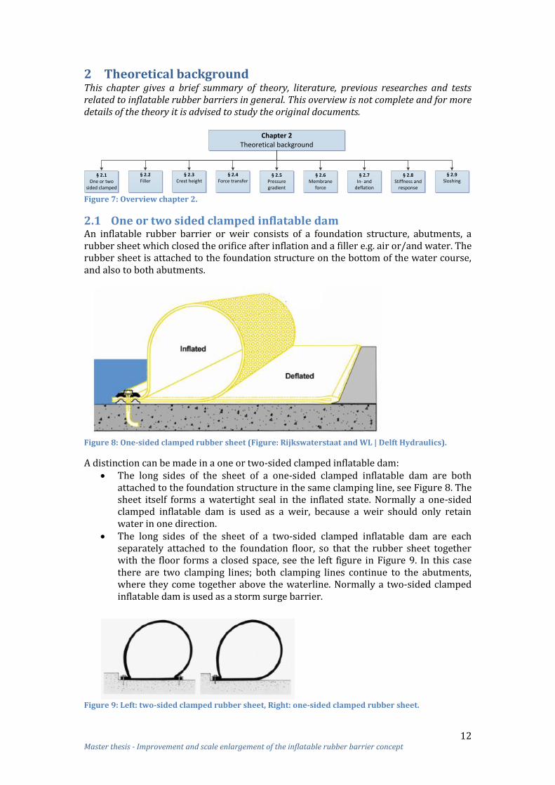
2.1 One or two sided clamped inflatable dam An inflatable rubber barrier or weir consists of a foundation structure, abutments, a rubber sheet which closed the orifice after inflation and a filler e.g. air or/and water. The rubber sheet is attached to the foundation structure on the bottom of the water course, and also to both abutments.
Figure 8: One-sided clamped rubber sheet (Figure: Rijkswaterstaat and WL | Delft Hydraulics).
A distinction can be made in a one or two-sided clamped inflatable dam: The long sides of the sheet of a one-sided clamped inflatable dam are both
attached to the foundation structure in the same clamping line, see Figure 8. The sheet itself forms a watertight seal in the inflated state. Normally a one-sided clamped inflatable dam is used as a weir, because a weir should only retain water in one direction.
The long sides of the sheet of a two-sided clamped inflatable dam are each separately attached to the foundation floor, so that the rubber sheet together with the floor forms a closed space, see the left figure in Figure 9. In this case there are two clamping lines; both clamping lines continue to the abutments, where they come together above the waterline. Normally a two-sided clamped inflatable dam is used as a storm surge barrier.
Figure 9: Left: two-sided clamped rubber sheet, Right: one-sided clamped rubber sheet.
13 Master thesis - Improvement and scale enlargement of the inflatable rubber barrier concept
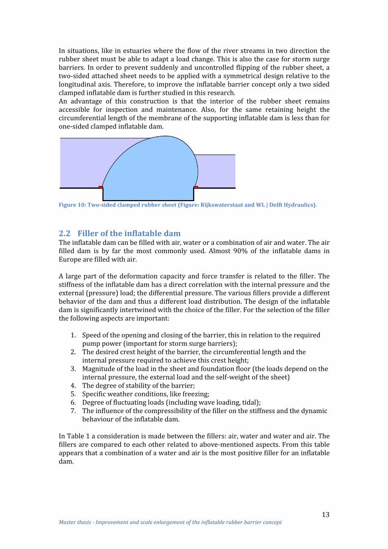
In situations, like in estuaries where the flow of the river streams in two direction the rubber sheet must be able to adapt a load change. This is also the case for storm surge barriers. In order to prevent suddenly and uncontrolled flipping of the rubber sheet, a two-sided attached sheet needs to be applied with a symmetrical design relative to the longitudinal axis. Therefore, to improve the inflatable barrier concept only a two sided clamped inflatable dam is further studied in this research. An advantage of this construction is that the interior of the rubber sheet remains accessible for inspection and maintenance. Also, for the same retaining height the circumferential length of the membrane of the supporting inflatable dam is less than for one-sided clamped inflatable dam.
Figure 10: Two-sided clamped rubber sheet (Figure: Rijkswaterstaat and WL | Delft Hydraulics).
2.2 Filler of the inflatable dam The inflatable dam can be filled with air, water or a combination of air and water. The air filled dam is by far the most commonly used. Almost 90% of the inflatable dams in Europe are filled with air. A large part of the deformation capacity and force transfer is related to the filler. The stiffness of the inflatable dam has a direct correlation with the internal pressure and the external (pressure) load; the differential pressure. The various fillers provide a different behavior of the dam and thus a different load distribution. The design of the inflatable dam is significantly intertwined with the choice of the filler. For the selection of the filler the following aspects are important:
1. Speed of the opening and closing of the barrier, this in relation to the required pump power (important for storm surge barriers);
2. The desired crest height of the barrier, the circumferential length and the internal pressure required to achieve this crest height;
3. Magnitude of the load in the sheet and foundation floor (the loads depend on the internal pressure, the external load and the self-weight of the sheet)
4. The degree of stability of the barrier; 5. Specific weather conditions, like freezing; 6. Degree of fluctuating loads (including wave loading, tidal); 7. The influence of the compressibility of the filler on the stiffness and the dynamic
behaviour of the inflatable dam. In Table 1 a consideration is made between the fillers: air, water and water and air. The fillers are compared to each other related to above-mentioned aspects. From this table appears that a combination of a water and air is the most positive filler for an inflatable dam.

14 Master thesis - Improvement and scale enlargement of the inflatable rubber barrier concept
Aspect: Filler: Water
Filler: Air
Filler: Water and air
Explanation:
1 -- + 0 Air is relatively easy to pump into the inflatable dam. Water requires more energy. For a water and air filled dam water can flow into the dam by gravity after the first air supply. For deflation the water must be pumped out.
2 - -- + For an air filled dam the internal pressure should be increased to withstand the hydrostatic pressure. For a water filled dam the filler causes that the internal pressure can be lower. A water filled dam requires a larger circumferential length. With a combination of both fillers the differential pressure can be minimal.
3 - -- + For an air filled dam the tension is high and its own weight is low. For a water filled dam the tension is lower and its own weight much higher. With a combination of both fillers it’s in between.
4 - -- - A water filled dam could move along with waves. An air filled dam has the tendency to V-notching. A combination of both fillers may cause sloshing in the dam due to the free water surface.
5 - + - Theoretically water could freeze, causing a loss of the flexibility. A rise of temperature might expand air.
6 0 0 + A water filled dam could move along with waves. A water and air filled dam can withstand several load combinations.
7 + - ++ For the combination of water and air this is adjustable due to the increase of the air pressure.
Result: Negative Negative Positive
Table 1: Considerations filler.
Disadvantages of a water filled inflatable dam: a larger dynamic load (due to the large pivoting water); a smaller retaining height (due to sagging of the dams by the water weight); a large pressure in the foundation will be present.
Disadvantages of an air filled inflatable dam:1
A large tension load will be present in the pile foundation; Sensitive for vibration in a spillway situation; V-notch phenomenon that occurs when the internal pressure is reduced and the
water flows over the dam; the bottom protection might be affected by the plunging jet.
Advantages of a filler with water and air are:1
For closing the inflatable dam only compressors for air are needed, the water flows naturally inward;
The shape and the pressure of the inflatable dam fits itself to the changing water levels; this is because the interior of the dam is connected with the upstream water;
The inflatable dam is during wave loads stiffer than a completely filled dam with air (see Appendix 2.4);
The foundation can be carried out lighter, because during retaining, water is present in the dam causing smaller tension forces in the foundation;
For deflation of the inflatable dam only water pumps are required; the air is pushed out of the dam due to the external water pressure.
1 Bouwdienst Rijkwaterstaat; Kennis- en Ervaringsdocument Balgkering Ramspol, December 2007, p. 11

15 Master thesis - Improvement and scale enlargement of the inflatable rubber barrier concept
2.3 Crest height of an inflatable dam General guidelines for the design of an inflatable dam construction are hard to find. However, a designer will usually be interested in the smallest dimension of the inflatable dam sheet, because the sheet has a major impact on costs. A good measure for the amount of sheet per unit width of the structure is the product of the membrane force (T) and the circumferential length (L). The membrane force determines the thickness of the material and how much reinforcement is needed. The membrane force together with the circumferential length is representative for the amount of material needed. The circumferential length (L) of an unloaded air filled dam will be minimal for the base width (B) equal to 0.9 times the crest height (H).2 The inflatable dam has now the shape of a circle, see Figure 11.
Figure 11: Two sided clamped inflatable dam (Figure: Rijkswaterstaat and WL | Delft Hydraulics).
With an external loading of the air filled dam, the crest height will rise. This means that the initial crest height Hunloaded can be chosen lower than the design crest height H. A water filled dam requires a larger circumferential length. The influence of a larger base width, sheet length, internal pressure and external pressure on the crest height are studied by J. Dorreman 19973 and is explained in Appendix 1.1. From this study can be concluded that a higher crest level can be reached by a larger base width (not too large), a larger sheet length and a larger internal pressure (only for air filled dams).
2.4 Force transfer When the inflatable dam is uniformly loaded in longitudinal direction and the sheet has uniform geometric and strength properties, also the hydraulic load is evenly distributed to the foundation. The load will be transferred in the circumference direction of the dam (through tensile forces in the membrane) to the clamping lines of the sheet and foundation floor. When the dam is not loaded uniform in the longitudinal direction, there might also be a load transfer to the adjacent sections, which is not desired.
2 Bouwdienst Rijkwaterstaat en WL| Delft Hydraulics, Hydraulische aspecten van balgstuwen en balgkeringen, Bouwdienst Rijkswaterstaat, December 2005, p. 3-17 3 Dorreman, J., Balgstuwen gevuld met luchten/ of met water, TU Delft, May 1997

16 Master thesis - Improvement and scale enlargement of the inflatable rubber barrier concept
In Figure 12 the force transfer of an inflatable rubber barrier with a bottom recess is given.
Figure 12: Force transfer inflatable rubber barrier with bottom recess.
A. Load due to the difference in water levels (head) and due to the internal pressure of the filler.
B. The load due to the pressure difference (p) is transferred to the two clamping lines as a tension force in the membrane.
C. The clamping line transfers the membrane force to the foundation. D. The forces in the clamping lines are distributed over the construction via the
foundation floor and if present transferred to the pile foundation. The design of the inflatable dam is significantly related with the choice of the filler. With a water filled dam a greater pressure is exerted on the foundation floor due to the weight of the water than in an air filled dam. The increased pressure on the foundation floor due to the water filled dam can be an advantage to balance the acting uplift force under the foundation. The membrane forces of a water filled dam are not necessary larger. When the soil contains weak layers, a small weight of the structure is advantageous. For the air filled dam tension piles might be needed.
The membrane force (T) is the result of the external load and the pressure in the inflatable dam (self-weight of sheet neglected). To keep T small the pressure difference p as an integral along the entire circumference of the inflatable dam needs to be minimized. The pressure difference (p) is the resulting pressure on the sheet, so the difference between internal and external pressure. The resulting pressure is generally directed outward, but with an air filled dam the resulting pressure can also locally act inwards. See Figure 13 for the internal and external loads on the water and air filled dam. To keep p small, and thus T, it is advantageous if the lowest possible internal pressure in the inflatable dam is set.
Figure 13: Forces on air and water inflatable dam.

17 Master thesis - Improvement and scale enlargement of the inflatable rubber barrier concept
For a two-sided clamped inflatable dam, the distribution of the horizontal load due to the difference in water levels ⁄
over both the two clamping
lines in the foundation is determined by the angle between the sheet and the horizontal, see Figure 14.
Figure 14: Load distribution over both clamping lines (Figure: Rijkswaterstaat and WL).
For the horizontal and vertical component of the clamping forces applies: The main part of the horizontal load H is transferred to the side with the smallest angle . The angle might be dependent on the shape of the inflatable dam, and thus dependent on the size of the load and the internal pressure. In an air filled dam with not too much internal pressure, the angle 1 is smaller than the angle 2 and so the main part of the horizontal load is transferred to the upstream clamping line. For a water filled dam the angle 1 is larger than the angle 2, see Figure 14. For both applies: The distribution of the horizontal load over the two clamping lines can be influenced by the internal pressure in the inflatable dam: the higher the internal pressure is set, the stiffer the dam, and the less the dam is tilted by the given external load, and thus the greater the angle 1 and 2. However, due to a higher internal pressure, the membrane force will increase what causes a higher force in the clamping lines and on the foundation floor.
2.5 Pressure gradient of an inflatable dam The pressure gradient of an inflatable dam depends on the internal and external pressure. In this paragraph the pressure gradient of the dam will be treated per filler. For scale enlargement of the inflatable dam it is important to know what the influence is of a larger inflatable dam (higher crest level) on the pressure gradient. This is discussed at the end of this paragraph. Air filled inflatable dam The pressure in an air filled inflatable dam is constant. The resulting pressure on the dam is constant at the parts of the dam that are in contact with the outside air. The inflatable dam has in these parts a circular shape when the weight of the sheet is neglected. See Figure 15 for the pressure in and on an air filled dam.

18 Master thesis - Improvement and scale enlargement of the inflatable rubber barrier concept
Figure 15: Pressure air filled inflatable dam (Figure: Rijkswaterstaat and WL | Delft Hydraulics).
At parts where the dam is in contact with the outside water, the resulting pressure varies linearly in the vertical and the dam has a non-circular shape. The curvature of the dam is directed inwards at the parts where the water pressure is greater than the effective internal pressure. Water filled inflatable dam For a water filled inflatable dam the piezometric head in the dam is a constant magnitude and the internal pressure is hydrostatic. On the part of the dam where also an outside water pressure present is, a constant resultant pressure on the dam will occur, see Figure 16.
Figure 16: Pressure water filled inflatable dam (Figure: Rijkswaterstaat and WL | Delft Hydraulics).
This results in a circular shape of the dam when the weight of the sheet is neglected. The parts of the dam that are not in contact with the outside water have a non-circular shape. Water and air filled inflatable dam The internal and external pressure gradient a water and air filled inflatable dam is shown in Figure 17. In this figure a kink is drawn between the straight and circular line., which in reality is not present. Also with such a high downstream water level it is better that the internal water level is higher than showed in the figure, because this results in a smaller resulting pressure.
Figure 17: Pressure water and air filled inflatable dam (Rijkswaterstaat + WL | Delft Hydraulics).
At the part of the inflatable dam where no resulting pressure present is, the dam has a straight shape has when the weight of the sheet is neglected. Circular shapes of the dam will occur at the parts where on both sides of the sheet air or water present is.

19 Master thesis - Improvement and scale enlargement of the inflatable rubber barrier concept
For a water and air filled inflatable dam the pressure in the dam of the internal water level is hydrostatic, but the pressure of the air in the dam needs to be added. The internal water could be in open connection with the upstream water. The internal water level of a water and air filled dam depends on the amount of air that is pumped into the dam. In the case of an open connection with the upstream water, the internal water level adjust itself so that the internal pressure (sum of the air and water pressure) in the inflatable dam is in equilibrium with the external water pressure of the upstream water side at the bottom. The effective air pressure in the dam is chosen such that the pressure difference as an integral along the entire circumference of the dam is minimal. From Figure 18 the following conclusion can be drawn: a higher internal water level causes a smaller resulting pressure along the sheet.
Figure 18: Pressure difference along sheet (Dirkmaat).
Unfortunately, the height of the internal water level is limited, because a minimum internal pressure should be present preventing the inflatable dam from sagging. Figure 19 shows for a water and air filled dam the shape due to a varying internal air pressure (Hin) and water pressure (h). The last picture in the figure shows that a too high internal water level causes a sagging of the dam.
Figure 19: Varying internal air and water pressure of water and air filled inflatable dam (Dirkmaat).
Higher crest height Sagging of the inflatable dam will occur when the external pressure is larger than the internal pressure. An inflatable dam with a higher crest height is in general loaded by a higher external pressure due to the larger water depths. A higher external pressure requires a higher internal pressure to prevent sagging of the dam. Thus, a higher crest height of the dam requires a higher internal pressure. More detailed information about the pressure gradient of an inflatable dam is given in Appendix 2.

20 Master thesis - Improvement and scale enlargement of the inflatable rubber barrier concept
2.6 Membrane force For scale enlargement of the inflatable dam it is important to understand how the membrane forces behave. Only the force transfer in circumferential direction is treated, because the transfer of force in the longitudinal direction is very small compared to the force transfer in normal direction.
2.6.1 Parbery equilibrium equations Some theory about the analysis of an inflatable rubber barrier has been published by various experts; in particular, [Harrison, 1970] and [Parbery, 1976]. The static load in an inflatable dam will be considered in the cross-section of the dam. This is because the inflatable dam transfers the tension membrane force over the entire length of the two clamping lines. See Figure 20 for a cross-section of an uniform inflatable dam, which is evenly loaded in longitudinal direction. Each element of the dam has a certain shape so that there is equilibrium between internal pressure, external load, weight of the sheet and membrane forces (normal forces in the circumferential direction of the dam).
Figure 20: Forces in an element with length dS* (Left: Parbery, 1976)
The static equilibrium of the element with unloaded length dS and loaded length dS* (S = coordinate in the circumferential direction of the inflatable dam) for the limiting case dS * 0 is described here below (see also [Parbery, 1976]):4
∑
Because is very small ∑
Because is very small and From the equilibrium equation for the tangential direction (circumferential direction) of the element, it follows that if the own weight w of the sheet is neglect, dT becomes zero.
4 Bouwdienst Rijkwaterstaat en WL| Delft Hydraulics, Hydraulische aspecten van balgstuwen en balgkeringen, Bouwdienst Rijkswaterstaat, December 2005, p. 3-3

21 Master thesis - Improvement and scale enlargement of the inflatable rubber barrier concept
With dT=0, the membrane force T in the circumferential direction is constant. The equation in radial direction becomes:
Dorreman has studied in 19975 the values of the external and internal pressure for the inflatable dam.
Figure 21: Forces in an element (Figure Dorreman)
In Table 2 and Table 3 the internal and external pressure for different conditions are given.
Filler Internal pressure due to Internal pressure
Water Water ⁄
Air Air
Water + air
Water ⁄
Air Table 2: Internal pressure.
External pressure due to External pressure
Water ⁄
Air - Table 3: External pressure.
The resultant pressure on the sheet is for different conditions given in Table 4.
Filler External pressure
Internal pressure
Resultant pressure p
Water water water ⁄
air water ⁄
Air water air ⁄
air air
Water + air water water
air water ⁄
water air ⁄
air air Table 4: Resultant pressure on sheet.
5 Dorreman, J., Balgstuwen gevuld met luchten/ of met water, TU Delft, May 1997

22 Master thesis - Improvement and scale enlargement of the inflatable rubber barrier concept
The extension of the sheet in the circumferential direction is in the case of uniform material given by the stress-strain relation (Hooke's law):
(
)
where t is the thickness of the sheet, and E is the modulus of elasticity in the circumferential direction. The curvature of the sheet is given by the following equation:
(curvature is positive for a deformation of the sheet in outward direction) Furthermore: ⁄ ⁄ The geometric boundary conditions are: (L = circumferential sheet length, B = horizontal distance between the clamping points) With the above set of equations and boundary conditions, the shape and the membrane force of an inflatable dam can be calculated, provided that the resulting pressure p as a function of S is known and also the weight w of the sheet. In the case of dynamic loads not only the external load changes as a function of the time but also the internal pressure in the inflatable dam; as a result, the sheet moves and deforms as a function of time and place. The membrane force is now not constant anymore, but varies as a function of time and place in circumferential direction. See Appendix 3 for the dynamic equilibrium of an inflatable dam. The theory just discussed for the static situation is processed in a 2D software model (MS Excel) by A. Dirkmaat.6 In paragraph 7.2.3 is this model described in detail.
2.6.2 Influences on membrane force For scale enlargement of an inflatable dam it is important to know what the influence is of a larger dam (higher crest) on the membrane forces. Dorreman7 has studied what the influence is on the membrane force due to a larger internal and external pressure, sheet length and base width. The results of his study will be treated in detail in Appendix 1.2. From this study can be concluded:
A larger width of the base increases the membrane force; A larger length of the sheet increases the membrane force; A larger internal pressure causes larger membrane forces; A larger external load causes smaller membrane forces.
In the study of Dorreman these parameters are studied independent of each other. The influence on the membrane force due to a combination of the above-mentioned parameters will be studied in chapter 7.
6 Dirkmaat A, Voorlopig Ontwerp Balgkering "Het Spui", Hogeschool Utrecht, August 2011 7 Dorreman, J., Balgstuwen gevuld met luchten/ of met water, TU Delft, mei 1997

23 Master thesis - Improvement and scale enlargement of the inflatable rubber barrier concept
2.7 In- and deflation of the barrier The way an inflatable dam raises itself during filling and sags again during deflation is strongly dependent on the filler and the hydraulic conditions during the in-and deflation.
When the inflatable dam is filled with air the parts above the abutments are generally the first part of the dam that are inflated above the water. It forms a V-notch. This V-notch is also present at the end of the filling and jumps right in the final stage of filling. During the deflation a V-notch will also occur.
Figure 22: V-notch during inflation of the inflatable dam of Ramspol.
This V-notch is also present for an inflatable dam filled with water and air when no current and water level difference is present, see Figure 22. For a water and air filled dam first the water inlet, which connect the inner side of the barrier with the upstream water level, is opened. At the same time the air valves on both sides of the barrier are opened and air is blown in by the blowers. As a result the air pressure inside the dam increases which causes the parts above the abutments to rise above the water level like pillows. At the same time the water flows in due the water head difference and increased volume. Due to the inflow of the water the sheet comes slowly out of the bottom recess. In the meantime the dam is further filled with air and water and a so-called V-notch is formed in the middle. Finally the dam rises above the water level and the barrier has closed off the stream. From that moment the supply of air continues for a while until the air pressure has reached the required level. Extra addition of air ensures that the desired level of the inside water level is achieved. The open connection with the upstream water remains intact. Sensors on the inside and outside of the dam detect what the desired water levels are. If the V-notch will be present during deflation depends on the way of emptying the dam. When first the air is blown off the inflatable dam, a dam filled with only water remains, causing that the deflation process will be the same as a for the water filled dam and no V-notch will be present. Filling with only water leads to a dam that is inflated simultaneously across the full width as showed in Figure 23.
Figure 23: Cross-section of the water filled inflatable dam during inflation.
Due to the opening of the water pipes some water flows in to the inflatable dam, but the inflation of the dam requires pumping of the water. During the deflation the dam drops simultaneously across the full width.

24 Master thesis - Improvement and scale enlargement of the inflatable rubber barrier concept
2.8 Stiffness and response of the inflatable dam Waves against a construction can cause time-varying loads. Due to a change of the local external load, the sheet will deform and displace in the normal plane, but at the same time, a resistance force will occur. The local resistance of the inflatable dam against displacements, also called the stiffness of the dam, is mainly provided by the internal and resultant pressure (the pressure difference across the sheet) and thus the membrane force. How larger the resultant pressure, how larger the stiffness. The stiffness is also partly provided by the compression stiffness of the filler, the radius of curvature R, the strain stiffness of the sheet and – in lesser extent – the bending and shear stiffness of the sheet. The stiffness of the inflatable dam is of great importance for the response of the dam. In general, an inflatable dam moves in a sweeping motion passively along with the incoming waves. With perpendicular waves, the motion is almost uniform over the length of the dam. The movement of the dam normally takes place with a period equal to the wave period. When the wave frequency is near the natural frequencies of the inflatable dam a strong resonance can occur. The determination of the natural frequencies is beyond the scope of this research. For a strong development of the movement of the inflatable dam the excitation must be periodic. In case of irregular waves (irregular wave height and period) which is normally the case, the development of the movement of the dam will be disturbed. The natural motions and frequencies of the inflatable dam are determined by the stiffness and mass of the dam including the filler and the surrounding water. The stiffer the dam, the lower the response. In general, it can be said that the response of an inflatable dam to wave loading with equal hydraulic conditions for an air filled dam is greater than for a water filled dam.8 This is partly due to the lower stiffness of the air filled dam, and partly because more force is required to bring the mass of the water in the inflatable dam in motion. In general the aim of the designer will be to achieve a high stiffness of the inflatable dam in order to limit the deformation of the dam. It is advantageous that the lowest natural frequencies of the inflatable dam is much higher than the wave frequencies. This prevents the dam from resonance. The advantage of a low stiffness of the inflatable dam on the other hand can be that the waves are less strongly reflected, which causes lower waves in front of the barrier and thus lower loads.
2.9 Sloshing The main dynamic loads for an inflatable dam are the loads caused by waves. The internal water in a water and air filled dam can brought in a wave-like motion (sloshing). Sloshing can occur both in the transverse direction and in the longitudinal direction of the dam. This sloshing movement has a natural frequency that is independent of the natural frequencies of the dam, and is mainly determined by the dimensions of the dam, and the height of the water in the dam. When the natural frequencies of these water movements corresponds to the frequencies of the moving inflatable dam, the water level in the dam might fluctuate. This might have an amplifying effect on the movement of the dam itself, but in case of irregular movements, the internal water movement might also have a disruptive effect.
8 Bouwdienst Rijkwaterstaat en WL| Delft Hydraulics, Hydraulische aspecten van balgstuwen en balgkeringen, Bouwdienst Rijkswaterstaat, December 2005, p. 6-18

25 Master thesis - Improvement and scale enlargement of the inflatable rubber barrier concept
Some theory about the behaviour of the internal water in the inflatable dam during perpendicular wave loads is studied by M. Cats in 19989. A sensitivity analysis is done to see which parameters an influence have on the height of the sloshing wave in the inflatable dam.
Figure 24: Sloshing in a water and air filled inflatable dam (Figure: Dorreman).
The rotation stiffness of the dam has the largest influence on the sloshing motion. The following aspects have an influence on the rotation stiffness:
Dimensions of the dam. The ratio between the sloshing mass and the rigid mass in the inflatable dam should be determined by the ratio of the internal water height and width of the dam. How larger the height relative to the width, the more water will be moved rigid and thus less sloshing.
Internal air pressure. The increase of the internal air pressure has also a favourable effect on the sloshing wave height. However, due to the increase of the air pressure in the inflatable dam a part of the internal water is pushed out of the dam due to the open connection with the upstream water level. When there is no open connection with the upstream water level an increase of the air pressure will cause a larger increase of the stiffness of the dam. Further the internal water level remains higher, which is favourable for the sloshing wave height.
Downstream water level. A lower downstream water level causes a larger stiffness of an inflatable dam. With a lower downstream water level the sloshing wave height will decrease. Therefore, it is favourable to inflate the dam with an as low as possible downstream water level. It is general not possible to change the upstream water level.
9 Cats M., Klotsen in een balgstuw, TU Delft, April 1998

26 Master thesis - Improvement and scale enlargement of the inflatable rubber barrier concept
3 Test results and studies related to the Ramspol barrier This chapter describes the test results and studies of the storm surge barrier of Ramspol in order to gain more insight into the advantages and disadvantages of the Ramspol barrier. At the end of this chapter a summary concerning the advantages and disadvantages of the inflatable barrier is given.
Chapter 3Test results and studies Ramspol
§ 3.1Final design
§ 3.2Sheet material
§ 3.3Manufacturing
sheet
§ 3.4Clamping structure
§ 3.5Bottom recess
§ 3.6Design
abutments
§ 3.7Design
formula
§ 3.8Reliability
§ 3.9Schematisation
§ 3.10Summary
Figure 25: Overview chapter 3.
3.1 Final design Ramspol barrier The barrier of Ramspol consist of three identical inflatable dams, each with a length of ca. 78 m (measured along the crest line) see Figure 26. One inflatable dam instead of three dams was not possible, because Ramsdiep is a shipping channel and Ramsgeul a flow channel. Nevertheless, three equal inflatable dams are built instead of a large and a small dam, because the failure probability of three equal dams is smaller than two dams, and the construction of three equal dams is cheaper and easier to design, execute and manage.10
Figure 26: Three identical inflatable dams of Ramspol.
Each inflatable dam has the following 2-D dimensions, see Figure 27: The circumferential sheet length: ; The base width: ; The crest height: NAP +3.55 m (which is 8.2 m above the clamps).
The dam consist of a water and air filler. The internal pressure at the level of the clamps is equal to the external pressure at the bottom of the upstream side. In Appendix 4 more information about the barrier of Ramspol is given.
Figure 27: Barrier of Ramspol.
10 Bouwdienst Rijkwaterstaat; Kennis- en Ervaringsdocument Balgkering Ramspol, December 2007, p. 10

27 Master thesis - Improvement and scale enlargement of the inflatable rubber barrier concept
With the given probability of failure of 10-5 per year ( and ) the probability of exceeding of the load level Sd for the ultimate limit state can be calculated with: With as the cumulative distribution function and as the reliability index. This probability of exceeding should be applied in situations in which the hydraulic conditions is the dominating load, which is the case for the ultimate limit state. The above mentioned probability of exceeding corresponds to the following load situation:
Upstream water level: 2.85 m +NAP Downstream water level: -0.40 m +NAP Head difference: 3.25 m Static load in sheet: 200 kN/m Internal water level: -0.88 m +NAP Internal air pressure: 37.3 kN/m2
The static load in sheet of 200 kN/m is the maximum static circumferential load in the sheet in the middle section at the location of the clamping. This is calculated with a mathematic model of the inflatable dam, based on the above mentioned water levels. The force distribution around the abutments is very complicated, causing that a 3D FEM model is needed. The same water levels and internal pressure of the calculation of the middle section are used for this calculation. These conditions result in local loads above the abutments considerably higher than the 200 kN/m, which occurred in the middle section. These local loads can be expressed due to a multiplier (stress concentration factor) related to the static load. In chapter 3.7 this factor is explained in more detail.
3.2 Material composition of the sheet Ramspol The membrane forces of the Ramspol barrier are larger than the membrane forces of the most existing weirs. Due to increased forces in the rubber body, the design for the barrier of Ramspol could not be based on proven materials applied for existing dams. The required strength of the sheet can be determined by using the static load and the estimation of the dynamic load. In order to reach sufficient strength for the sheet, a number of materials can be applied. During the scale model tests, multiple materials have been studied and compared with each other in order to find a suitable material for the sheet, see Table 5.
Material PP PA6 PES ARA DYN
Tensile strength [MPa] 600 900 1100 2900 3000 Elongation at break [%] 20 20 13 3.6 3.6 Table 5: Stiffness properties of the sheet materials applied in the scale model.
Five materials are tested: PP (Polypropeen), PA6 (Polyamide 6, with the commonly used name: Nylon), PES (Polyester), Aramid and Dyneema®. Also POM (polyacetaal) is initially considered, but it appeared that this material was not applicable below temperatures of 5 .11 Aramid is the name of the meta-and para-aramid fibers. It is sold under the trade names Kevlar®, Nomex ® (both produced by Dupont), Twaron® and Technora® (both produced by Teijin). Dyneema® is a high modulus polyethylene (HMPE) fiber and is a registered trademark of DSM. 11 Bouwdienst Rijkwaterstaat; Kennis- en Ervaringsdocument Balgkering Ramspol, December 2007, p. 22

28 Master thesis - Improvement and scale enlargement of the inflatable rubber barrier concept
In an initial design a rubber body reinforced with a Kevlar® fabric was developed. In the final design, the initial stiff Kevlar® reinforcement is replaced by a less stiff Nylon reinforcement. Although a sheet with Kevlar® is stronger than a sheet with Nylon, for the design of the sheet Nylon is still chosen, because of the material behaviour of Kevlar®. Sheets reinforced with Kevlar® are stronger, but also much stiffer. This stiffness disadvantage causes much higher dynamic forces and the stress concentrations in the sheet above the abutments. This disadvantage is outweighed by the advantage of greater strength. For the sheet material of the inflatable dam of Ramspol is chosen for PA6 in combination with rubber as matrix material for the following reasons:11
The relative large strength of the available sheets of PA6; Circa 30 years’ experience with thousands of inflatable dams with PA6 as sheet
material; The need for relative much strain for the decrease of the stress concentrations at
discontinuities at the location of the clamping; Aramid is sensitive for wear and compression: fibres snap. A large disadvantage
is that due to the high stiffness larger stress concentrations will be present. This applies also for Dyneema;
PES has also a higher stiffness and a less good adhering to rubber than PA6; PP does not adhere well to rubber: fibres can be drawn out of the rubber; The prevention of extrapolation in size in combination with a sheet material that
is stiff and never used for inflatable dams; In the final design of the Ramspol barrier a rubber body reinforced with Nylon fabrics has been developed. The rubber body consist of two thick layers of Nylon fabric and four smaller layers of Nylon fabric for the forces in warp and longitudinal direction respectively, see Figure 28.
Figure 28: Rubber sheet reinforced with aramid fabric (Figure: Rövekamp).
On both sides, the inner and outside, the fabric is protected with a layer of rubber, see Figure 29.
Figure 29: Rubber sheet reinforced with aramid fabric.
There is no interaction between the longitudinal- and circumferential yarns due to the choice of the fabric: reinforcement in circumferential direction (warp) and reinforcement in longitudinal direction are not connected by weft, but by a connection of separate yarns. As a result the longitudinal- and circumferential fabrics can stretch independent of each other.

29 Master thesis - Improvement and scale enlargement of the inflatable rubber barrier concept
The average initial strength of this rubber sheet in the direction of the circumferential is approximately 1900 kN/m. After fatigue loading, ageing and relaxation from pre-stresses the strength of the sheet was ca. 970 kN/m. The material properties in warp and longitudinal direction differ quit a lot. The initial strength in longitudinal direction is 450 kN/m. Also the strain stiffness EA of the sheet in longitudinal direction of the inflatable dam is considerably lower (3200 kN/m) than the strain stiffness in circumference direction (5700 kN/m). More information about the material of the sheet is given in Appendix 5.
The calculated lifetime of the sheet is minimal 25 years. Because of the conservative assumptions and loads in the test, it is assumed that the lifetime of the sheet can be significant higher. In order to check this, periodically destructive strength tests are performed on the sheet. Expected is that with these tests a lifetime of another 25 years can be justified. This is a huge cost saving potential.
3.3 Manufacturing of the rubber sheet The sheets of the inflatable dams of Ramspol consist of a rubber body reinforced with a Nylon fabric. In that time, no production line in the Netherlands was able to vulcanize this rubber sheet with the desired strength and dimensions. In Japan two suppliers were able to produce the sheets for the inflatable dams, namely Sumitomo and Bridgestone. These manufacturers have both a different production method. The most important difference between both methods are:12
Sumitomo vulcanizes under elevated temperature the whole sheet in one time. Bridgestone vulcanizes under elevated temperature and pressure first strips
which are vulcanized against each other until the desired length is achieved. The selected supplier of the sheets of Ramspol was Bridgestone. The production method is to vulcanize under elevated temperature and pressure first strips of 175 meter long and a few meters wide. These strips are cut in sections of 25 meter long (the circumferential length of the dam), see Figure 30.
Figure 30: Sheet for the inflatable dam of Ramspol (Figure: Bouwdienst Rijkwaterstaat).
The long sides of these sections are vulcanized against each other; the vulcanized surface is pre-enlarged by cutting the sides in steps, see Figure 31.
Figure 31: Joint – Cross-section sheet in longitudinal direction (Figure: Bouwdienst Rijkwaterstaat).
12 Bouwdienst Rijkwaterstaat; Kennis- en Ervaringsdocument Balgkering Ramspol, December 2007, p. 20

30 Master thesis - Improvement and scale enlargement of the inflatable rubber barrier concept
From some tests appeared that the joints fulfil the required strength. Therefore, it can be said that it is no disadvantage when the sheet of the inflatable dam consist of sections connected in longitudinal direction. The production method of the sheets is explained in Appendix 6.
Figure 32: Unrolled sheet near the final location Ramspol (Photo: Bouwdienst Rijkwaterstaat).
In the design for Ramspol, the sheet has a completely flat form in dissembled condition, see Figure 32. This is a great advantage, both in manufacture as well as in the assembly of the sheet.
3.4 Clamping structure During the design phase of the barrier of Ramspol research was started to find an optimal clamping structure. Because calculation models were in that time inadequate and sheet manufactures had their own clamping structures, this research was terminated without any result. With the currently available software programs the development of new clamping structures seems feasible. This can result in a favourable multiplier factor with respect to the clamping and might cause a cost reduction. The development of a new clamping structure is beyond the scope of this research.
There are several clamping structures available, see Appendix 7. The wave clamp is selected for the inflatable dam of Ramspol, because of the experience of the manufacturer (Bridgestone) with these clamps. The clamp is composed of a wavy top and bottom plate, between which the sheet is clamped using pre-stressed bolds. For the clamping of the sheet in the horizontal part of dam a so called ‘teeth’ clamp is used. This clamp consist of a bottom plate (embedded plate) and a top plate (clamping plate) between which the sheet is clamped, see Figure 33. This whole is attached to the concrete foundation with pre-stressed bolts with a centre-to-centre distance of 150 mm.
Figure 33: Teeth clamp for horizontal part.

31 Master thesis - Improvement and scale enlargement of the inflatable rubber barrier concept
For the abutment part a different clamp is needed; a clamp which is waved in two directions. The first direction is in the load direction of the sheet, perpendicular to the clamping line. The other direction is in longitudinal direction of the sheet. For this purpose a Small Wave clamp is developed, see Figure 34. In paragraph 3.6 is the explanation given why a different clamp for the abutment part is needed.
Figure 34: Small wave clamp for abutment part.
The double waved clamping structure on the abutment causes many forced strains in the sheet. This could be a problem for an Aramid reinforcement which is very stiff and has a relatively brittle failure mode, but not for Polyamide fibres which have a ductile behaviour with an elongation at break of 20%. For the sheet of Ramspol Polyamide 6 is used as reinforcement which will not give significant problems due to its ductile behaviour. It is important to include a number of protection measures:
The steel of the clamp should be protected against corrosion. Because the surfaces of the clamp and the fasteners are made of the same material, there will be no galvanic corrosion;
There is no water entering the clamp due to water repellent grease under the cap nuts (water accession could lead to corrosion);
The space between the anchors and anchor holes is closed by means of an elastic wrapping band which permits anchor stretching when the anchor load is applied.
3.5 Bottom recess Ramspol For a two-sided attached sheet specific requirements are necessary to keep the sheet in place during and after the deflation. The sheet should not bulge or get loose of the foundation, otherwise danger of ship collision or flow blockage can occur. With a bottom recess there is less chance of blocking the flow or forming an obstacle for ships. For the barrier of Ramspol a scale model with rotating guide rollers as showed in Figure 35 was studied by BAM/ Bridgestone. See Appendix 8 for more detailed information about the bottom recess of Ramspol.
Figure 35: Scale model with rotating guide rollers (Photo WL | Delft Hydraulics).

32 Master thesis - Improvement and scale enlargement of the inflatable rubber barrier concept
The influence on the storing process of the sheet in a bottom recess due to the layout of the abutments was also studied. In the scale model study13 of T.H.G. Jongeling in 1998 different variants of rollers on the abutments were tested, see Figure 36. The layout of the abutments were adapted with fixed or rotating corner spacers, rollers and shallow or deep recess abutments.
Figure 36: Left: fixed corner spacers; Middle: rollers on abutment; Right: rotating corner spacers.
Conclusion of the test results was that in the final situation large, sharp folds occurred in the sheet above the abutments, see Figure 37. Neither the rollers on the abutments, nor the corner spacers could prevent the formation of these folds. Due to these test results, the final design is the variant with four rollers in the bottom recess and no corner spacers and rollers on the abutments.
Figure 37: Fold formation above abutment in deflated state, Left: scale model, Right: Ramspol.
Another result of the scale model test was that for an air filled dam the storing of the sheet in the bottom recess is more difficult than for a water filled dam. The most important reason for this is that an air filled dam does not drop simultaneously across the full width during deflation. For the deflation of the Ramspol barrier only water pumps are used; the air is pushed out of the dam due to external water pressure. The expected deflation and storing process of the inflatable dam of Ramspol is different than in practice. It was expected that during the deflation, the dam settles and the middle section sinks below the water surface until it lays on the bottom at the downstream side, see Figure 38.
13 WL Delft Hydraulics, Modified design of abutments, June 1998

33 Master thesis - Improvement and scale enlargement of the inflatable rubber barrier concept
Figure 38: Cross-sections bottom recess, phase 1 of deflation (Figure Jongeling + Rövekamp).
From this moment the sheet has to be redistributed over the five trenches between the rollers. First the sheet is sucked into the first trench seen from the downstream side, Figure 39.
Figure 39: Cross-sections bottom recess, phase 2 of deflation (Figure Jongeling + Rövekamp).
Subsequently redistribution of the sheet across the recess takes place, but in the final situation only the first two trenches are fully filled, while the sheet in the last three has no contact with the floor, see Figure 40. During the model test sometimes a large fold remains in the first trench, but in all cases the fold stayed well below the top of the concrete sill.
Figure 40: Cross-sections bottom recess, phase 3 of deflation (Figure Jongeling + Rövekamp).
In practice, the storing of the sheet does not proceed as explained above which has been shown during the test closure of the Ramspol barrier in 2004. After finishing the opening stage, it turned out that the sheet of the inflatable dam had been stored incorrectly in the bottom recess. The sheet was distributed unevenly over the rollers and a flap occurred due to the overlength, see Figure 41. This flap had such a height (3.1 m) that it rises above the bottom recess and was hit by a passing vessel. The sheet was not damaged by the vessel. Due to this incident, the main contractor BAM has adapted the software system such that the sheet is being deflated in two stages; pressure management (adjustment of the water and air pressure regulation).
Figure 41: A flap due to not evenly distributed sheet.
During a storm closure in 2006 it turned out that the adaption in the software system had an insufficient effect. Still a flap of 30-60 cm occurred above the bottom recess. In almost all the cases both sides of the fold were sucked against each other at the bottom which leads to water / air inclusion at the top in the fold. It can be concluded that in practice it is always possible that some folds rise above the bottom recess. Large folds are impermissible, because the sheet is vulnerable to collisions. Folds around 20 – 30 cm are not vulnerable to collisions and will disappear in time.
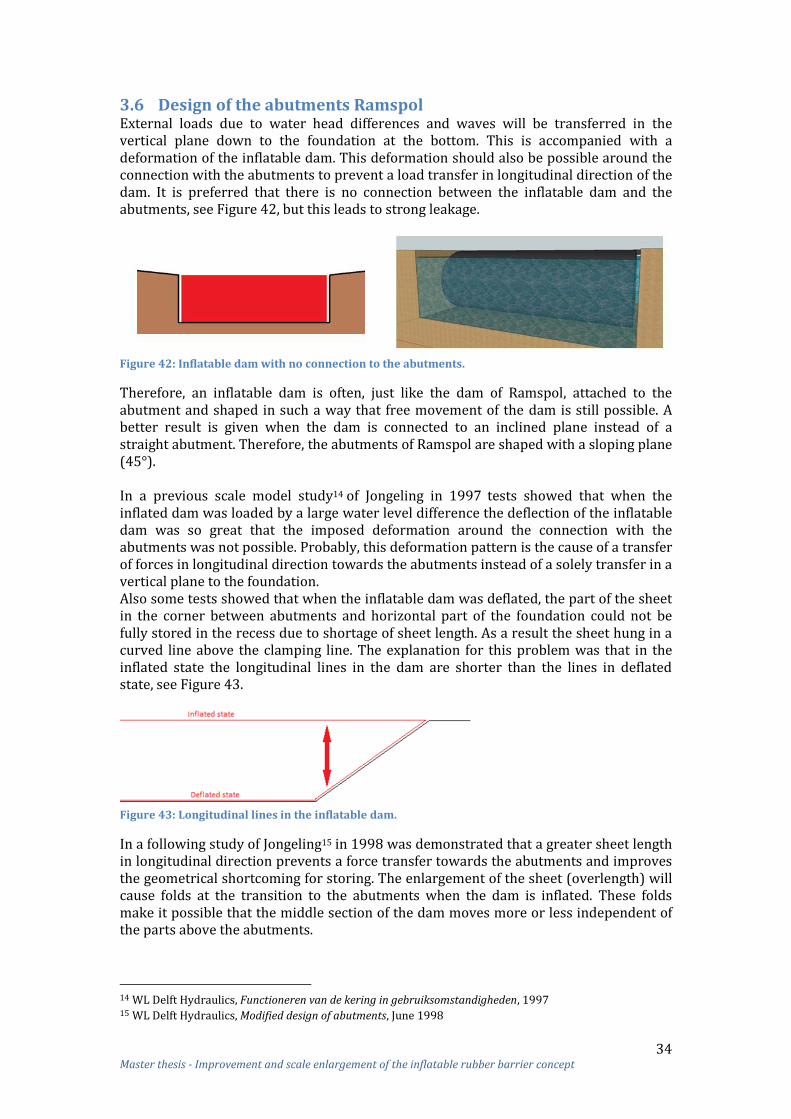
34 Master thesis - Improvement and scale enlargement of the inflatable rubber barrier concept
3.6 Design of the abutments Ramspol External loads due to water head differences and waves will be transferred in the vertical plane down to the foundation at the bottom. This is accompanied with a deformation of the inflatable dam. This deformation should also be possible around the connection with the abutments to prevent a load transfer in longitudinal direction of the dam. It is preferred that there is no connection between the inflatable dam and the abutments, see Figure 42, but this leads to strong leakage.
Figure 42: Inflatable dam with no connection to the abutments.
Therefore, an inflatable dam is often, just like the dam of Ramspol, attached to the abutment and shaped in such a way that free movement of the dam is still possible. A better result is given when the dam is connected to an inclined plane instead of a straight abutment. Therefore, the abutments of Ramspol are shaped with a sloping plane (45 ). In a previous scale model study14 of Jongeling in 1997 tests showed that when the inflated dam was loaded by a large water level difference the deflection of the inflatable dam was so great that the imposed deformation around the connection with the abutments was not possible. Probably, this deformation pattern is the cause of a transfer of forces in longitudinal direction towards the abutments instead of a solely transfer in a vertical plane to the foundation. Also some tests showed that when the inflatable dam was deflated, the part of the sheet in the corner between abutments and horizontal part of the foundation could not be fully stored in the recess due to shortage of sheet length. As a result the sheet hung in a curved line above the clamping line. The explanation for this problem was that in the inflated state the longitudinal lines in the dam are shorter than the lines in deflated state, see Figure 43.
Figure 43: Longitudinal lines in the inflatable dam.
In a following study of Jongeling15 in 1998 was demonstrated that a greater sheet length in longitudinal direction prevents a force transfer towards the abutments and improves the geometrical shortcoming for storing. The enlargement of the sheet (overlength) will cause folds at the transition to the abutments when the dam is inflated. These folds make it possible that the middle section of the dam moves more or less independent of the parts above the abutments.
14 WL Delft Hydraulics, Functioneren van de kering in gebruiksomstandigheden, 1997 15 WL Delft Hydraulics, Modified design of abutments, June 1998

35 Master thesis - Improvement and scale enlargement of the inflatable rubber barrier concept
Several options were developed to clamp this overlength, see Appendix 4.4. Finally, a geometry was found where the stress concentrations were small enough to be tolerated by the rubber sheet. In this design the initial too high stress concentrations in the sheet are reduced by adjusting the shape of the transition structure such that the overlength of the sheet could be distributed evenly (stepwise) over the abutment. The steps on which the sheet should be distributed were initially quite large; real stairs in a concrete structure at the abutment. This resulted in high stress concentrations. Therefore, the size of the steps were reduced by waves in the clamping structure, the so called ‘Small Wave clamp’, see Figure 44 and paragraph 3.4.
Figure 44: Stepwise clamping structure Ramspol.
With these clamps much smaller stress concentrations occurred in the sheet. However, still some peak stresses and folds will arise in the sheet due to the not evenly distributed normal force, see Figure 45.
Figure 45: Peak stresses in stepwise clamped sheet above the abutment.
The largest folds occurred in the transition site between the horizontal and the sloping part, see Figure 46. Smaller, distributed folds occurred along the stepped clamps on the abutments.
Figure 46: Folds in Ramspol barrier (Photo: Bouwdienst Rijkswaterstaat).
Folds in the sheet are not desired because they result in stress concentrations, increase the probability of a leak and can be the cause for deflation problems.
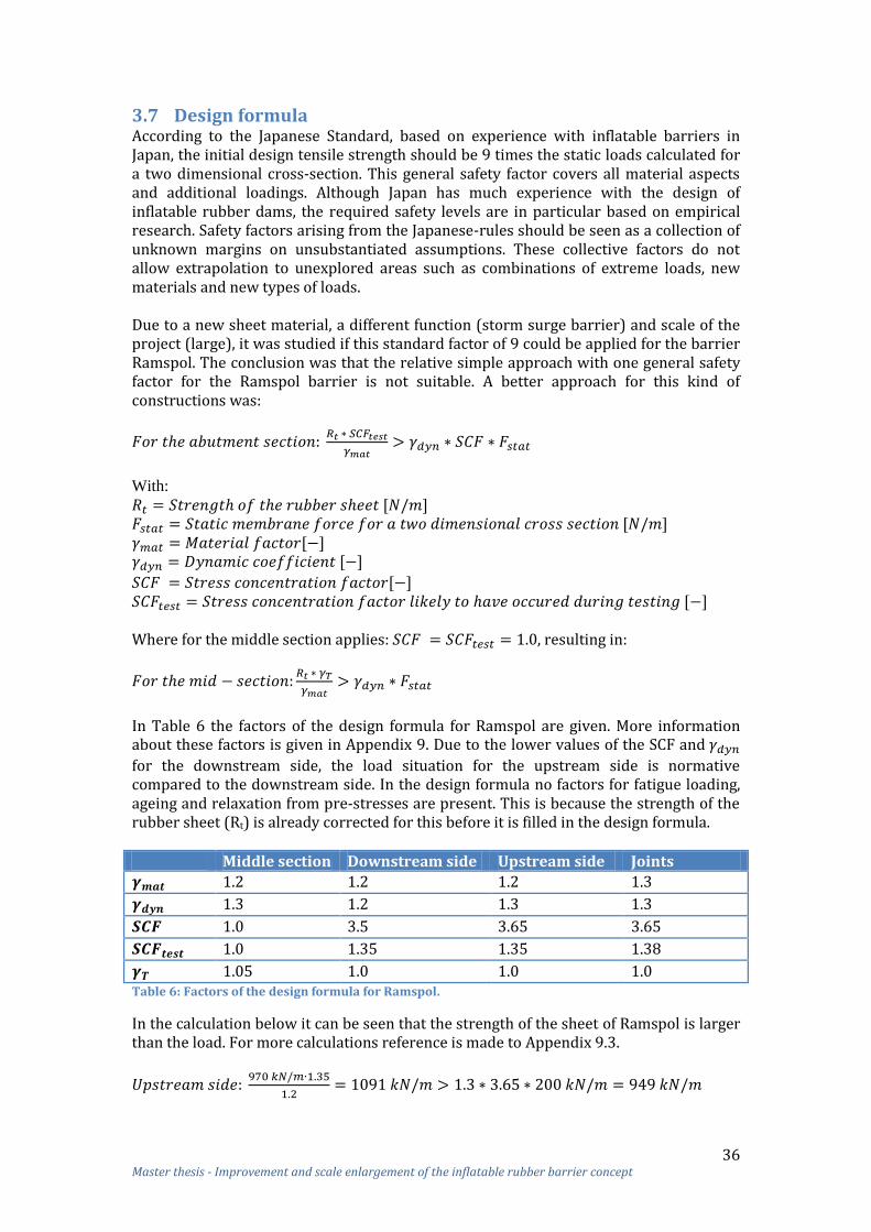
36 Master thesis - Improvement and scale enlargement of the inflatable rubber barrier concept
3.7 Design formula According to the Japanese Standard, based on experience with inflatable barriers in Japan, the initial design tensile strength should be 9 times the static loads calculated for a two dimensional cross-section. This general safety factor covers all material aspects and additional loadings. Although Japan has much experience with the design of inflatable rubber dams, the required safety levels are in particular based on empirical research. Safety factors arising from the Japanese-rules should be seen as a collection of unknown margins on unsubstantiated assumptions. These collective factors do not allow extrapolation to unexplored areas such as combinations of extreme loads, new materials and new types of loads. Due to a new sheet material, a different function (storm surge barrier) and scale of the project (large), it was studied if this standard factor of 9 could be applied for the barrier Ramspol. The conclusion was that the relative simple approach with one general safety factor for the Ramspol barrier is not suitable. A better approach for this kind of constructions was:
With:
Where for the middle section applies: , resulting in:
In Table 6 the factors of the design formula for Ramspol are given. More information about these factors is given in Appendix 9. Due to the lower values of the SCF and
for the downstream side, the load situation for the upstream side is normative compared to the downstream side. In the design formula no factors for fatigue loading, ageing and relaxation from pre-stresses are present. This is because the strength of the rubber sheet (Rt) is already corrected for this before it is filled in the design formula. Middle section Downstream side Upstream side Joints
1.2 1.2 1.2 1.3
1.3 1.2 1.3 1.3
1.0 3.5 3.65 3.65
1.0 1.35 1.35 1.38
1.05 1.0 1.0 1.0 Table 6: Factors of the design formula for Ramspol.
In the calculation below it can be seen that the strength of the sheet of Ramspol is larger than the load. For more calculations reference is made to Appendix 9.3.

37 Master thesis - Improvement and scale enlargement of the inflatable rubber barrier concept
The stress concentration factor has the largest value compared to the other factors of the design formula and depends on the geometry of the abutment. The second largest factor, the dynamic coefficient depends on the wave conditions, the sheet material and the stiffness of the inflatable dam. The partial safety factor and the material factor are very small and its value is more or less fixed. The high value of the stress concentration factor shows that the geometry of the abutment is a problem area. The sheet strength in longitudinal direction is not tested. However, a calculation is made and the rule of thumb from Japan that the strength in longitudinal direction should be 30% of the strength in circumferential direction, is satisfied. It is not demonstrated that a strength in longitudinal direction of 30% is too little.
3.8 Reliability For the barrier of Ramspol a risk analysis is made. In this analysis a distinction is made between constructive failure and systems failure. Constructive failure includes failure of civil parts, steel constructions and the rubber sheet and has a relatively small contribution to the total failure probability. The failure of the systems includes collision, fire, software, electrical energy, mechanical, decide and control, maintenance, et cetera and has a normative contribution to the total failure. In Figure 47 the failure probability is given for the inflation phase, as studied a few years ago. Constructive failure is not included in this figure.
Figure 47: Failure probability of several failure categories (Presentation Probabilistic Asset Management Storm Surge Barrier Ramspol).
The failure probability of the categories electrical energy, mechanical and software are relative high compared to the other categories. Recently two measures are taken in order to decrease the failure probability of the categories electrical energy and software, see Figure 48.
Figure 48: Reduction failure probability due to some measures.

38 Master thesis - Improvement and scale enlargement of the inflatable rubber barrier concept
One of the measures was the installation of an emergency power generator, which decreased the failure probability concerning electrical energy with 21%.16 The other measure was the entering of a manual closing procedure instead of only an automatic closing procedure, which decreased the failure probability of the category software with 23%.16 More information about the measures is given in paragraph 7.1. For the failure probability analysis a distinction can be made between the inflation phase, retaining phase and deflation phase. For each phase a different failure probability can be present. See Appendix 10.1 for more information. Some systems failure mechanisms per category:
Collision: o Collision due to conscious and unconscious vandalism; o Collision due to ignoring or not observes the stop signs; o Collision due to incorrect storing of the sheet (protruding flap of sheet); o Collision due to boat auxiliaries, like anchors.
Software: o Software failure due to errors in program; o Software failure due to hacking; o Software failure due to incorrect use;
Electrical energy: o Power supply and/ or transformers failure due to power cuts; o Power supply and/ or transformers failure due to water damage.
Mechanical: o Pumping system, valves and/or pipes failure due to sedimentations; o Pumping system, valves and/or pipes failure due corrosion; o Valves and/or pipes failure due to settlements; o Valves and/or pipes failure due to water hammering.
Some constructive failure mechanisms:
Rubber sheet: o Sheet failure due to the vulnerability of the membrane (ice, floating
debris, vandalism, fold formation, bad storage, collision, UV, boat auxiliaries, like anchors);
o Progressive collapse sheet; o Collapse of the sheet due incorrect use of the pumps and blowers; o Deflation of the sheet due incorrect use of the pumps and blowers.
Civil: o Foundation failure due to uplifting; o Foundation failure due to shearing; o Foundation failure due to insufficient rotational stability; o Foundation failure due to insufficient bearing capacity of the soil; o Foundation failure due to settlement; o Foundation failure due to insufficient stability of the slopes (slip circle); o Foundation failure due to piping.
The Ramspol barrier is designed on the basis of a risk analysis. As a result of the risk analysis the following significant risks need more attentions for similar projects: maintenance, risk of collision, thunderstorm, software, fire and some inflatable dam specific risks.17 These risks are discussed in more detail in Appendix 10.2.
16 Presentation Probabilistic Asset Management Storm Surge Barrier Ramspol, 25-04-2013 17 Bouwdienst Rijkswaterstaat, Kennis- en Ervaringsdocument Balgkering Ramspol, 2007, p. 11-13

39 Master thesis - Improvement and scale enlargement of the inflatable rubber barrier concept
3.9 Overview Ramspol barrier In this paragraph a short overview of the Ramspol barrier is given. Dimensions In Figure 49 a cross-section of the IRB of Ramspol is given.
Figure 49: Barrier of Ramspol.
In Table 7 some data of the IRB of Ramspol is given. This data is associated with a probability of exceeding the load level for the ultimate limit state of .
Parameter Value
Crest height +3.55 m +NAP
Base level -4.65 m +NAP
Internal water level -0.88 m +NAP
Internal air pressure 37.3 kN/m2 Upstream water level 2.85 m +NAP
Downstream water level -0.40 m +NAP
Head difference 3.25 m Table 7: Data IRB Ramspol.
The circumferential length and base width of the inflatable dam are dependent on the crest height, see Table 8.
Parameter Formula Value
Circumferential sheet length 24.3 m
Base width 13 m Table 8: Circumferential length and base width of Ramspol IRB.
The internal water remains in open connection with the upstream water. As a result, the internal water level depends on the amount of air that is pumped into the inflatable dam. The internal pressure (sum of the air and water pressure) is in equilibrium with the external upstream water pressure: HW=Pinternal=Pair+h. Force transfer The load due to the difference in water levels ⁄
and internal
pressure of the filler causes a pressure difference in the sheet which is transferred in the circumference direction of the dam as a tension force in the membrane (T) to the clamping lines and foundation. The distribution of the load over both the two clamping lines in the foundation is determined by the angle between the sheet and the horizontal. For the horizontal and vertical component of the clamping forces applies:

40 Master thesis - Improvement and scale enlargement of the inflatable rubber barrier concept
The maximum static circumferential load in the sheet in the middle section of the IRB of Ramspol is 200 kN/m. The maximum design load is much higher than the static load due to dynamic loading, stress concentrations in the sheet, et cetera. A design formula is developed for Ramspol to calculate the maximum design load and strength:
Where:
Middle
section Downstream side
Upstream side
Joints
[-] 1.2 1.2 1.2 1.3
[-] 1.3 1.2 1.3 1.3
[-] 1.0 3.5 3.65 3.65
[-] 1.0 1.35 1.35 1.38
[-] 1.05 1.0 1.0 1.0 Table 9: Factors of the design formula for Ramspol.
Folds and peak stresses To prevent a load transfer in longitudinal direction towards the abutments, the dam must have enough freedom of movement (i.e. leeway) around the transition to the abutments. Therefore, the length of the sheet in longitudinal direction is increased which will cause folds and high stresses in the sheet around the transition when the dam is inflated, see Figure 50. Due to the enlargement of the sheet a double-waved clamping structure on the abutment is needed which causes also many folds and high stresses in the sheet around the clamping line.
Figure 50: Folds and peak stresses in sheet Ramspol above abutment.
Sheet material The sheet consist of two thick layers of Nylon fabric and four smaller layers of Nylon fabric for the forces in warp and longitudinal direction respectively, see Figure 51. On both sides, the inner and outside, the fabric is protected with a layer of rubber.
Figure 51: Rubber sheet reinforced with aramid fabric (Figure: Rövekamp).

41 Master thesis - Improvement and scale enlargement of the inflatable rubber barrier concept
In Table 10 the strength and stiffness properties of the rubber sheet is given.
Parameter Value
Initial strength in circumferential direction 1900 kN/m
Strength after loading in circumferential direction 970 kN/m
Initial strength in longitudinal direction 450 kN/m Strain stiffness in circumference direction 5700 kN/m
Strain stiffness in longitudinal direction 3200 kN/m Table 10: Strength and stiffness properties of the rubber sheet.
Clamping structure For the clamping of the sheet in the horizontal part of dam a so called ‘teeth’ clamp is used. This clamp consist of a bottom plate (embedded plate) and a top plate (clamping plate) between which the sheet is clamped. For the abutment part a different clamp is needed; a clamp which is waved in two directions in order to clamp the overlength of the sheet evenly (stepwise) over the abutment. The double waved clamping structure on the abutment causes many forced strains in the sheet. Bottom recess When the inflatable dam of Ramspol is deflated the sheet should be stored in a bottom recess with four rows of rotating rollers. For the deflation of the Ramspol barrier only water pumps are used; the air is pushed out of the dam due to external water pressure. It was expected that during the deflation, the dam completely fall to one side due to the water flow and is then forced by vacuum pressure below the sheet into the five trenches between the rollers. In practice it appears regularly that the sheet is distributed unevenly over the rollers and a flap occurs. In order to improve the storage of the sheet the software system has been adapted such that the sheet is being deflated in two stages; pressure management (adjustment of the water and air pressure regulation). This adaption in the software system had still an insufficient effect.
42 Master thesis - Improvement and scale enlargement of the inflatable rubber barrier concept
3.10 Summary of advantages and disadvantages This paragraph presents a summary of advantages and disadvantages of the inflatable barrier as discussed in the previous paragraphs.
3.10.1 Advantages The advantages should be maintained for the improvement and scale enlargement of the inflatable rubber barrier concept. Lower stiffness than traditional barriers Inflatable rubber barriers move relatively strongly along with the incoming waves and cause less reflection. This moving of the inflatable dam causes that the local waves in front of the dam are less high and as a result less high loads will be present than in the case of a rigid construction. Large span possible When the inflatable dam is uniform loaded in longitudinal direction and the sheet has uniform geometric and strength properties, the hydraulic load is evenly distributed to the foundation. The span of inflatable dams has therefore no restrictions and no or less intermediate pillars are needed. The length of the sheet is also not limited, because the sheet can be connected to each other on the site. Less maintenance For the sheet often a material as durable rubber reinforced with synthetic fibers e.g. nylon or polyester is selected. Due to these materials corrosion is impossible. Also no moving components are situated under water. Therefore, less maintenance is needed than for the traditional barriers with steel doors. Low environmental impact Most of the time the inflatable dam is deflated and thus located under water. Because less pillars are needed than for traditional barriers, the flow of the water will be minimal disturbed when the dam is deflated. There is also less visual pollution when the dam is deflated. Low costs The costs of an inflatable rubber barrier are relatively low (approximately € 0.5 million per metre barrier length) compared to traditional barriers (approximately € 4 million per metre barrier length), due to the ease of placement and construction. The sheet and foundation are the most expensive parts of the barrier. Inflatable rubber barriers have per metre barrier length Low self-weight An inflatable dam consist of a foundation floor and a rubber sheet. Because most traditional barriers consist of steel doors instead of a rubber sheet, the weight is much larger than the weight of an inflatable dam. The lower weight of the structure is advantageous, especially when the soil contains weak layers. Different fillers and combinations possible The current inflatable dams are filled with water, air or a combination of water and air. Probably another filler instead of water or air can be used, but because water and air are available in the environment, these fillers are preferred. A water and air filled dam has more advantages than a dam filled with water or air. Due to the advantages of the combination of water and air, a dam filled with water air should be preference.

43 Master thesis - Improvement and scale enlargement of the inflatable rubber barrier concept
3.10.2 Disadvantages The following disadvantages of inflatable barriers are derived from the theory and tests related to the IRBs and the barrier of Ramspol. Lack of knowledge about the limits of the dimensions of an inflatable dam There is less information and experience available about the limits of the dimensions of an inflatable rubber barrier. To date, the largest IRB is Ramspol. When an IRB with larger dimensions is required no guidelines are available. Fold formation due to the design of the abutments The inflatable dam is shaped in such a way (enlargement of the sheet in longitudinal direction) that a free movement of the dam is possible around the abutments and that the sheet can be stored properly. The enlargement of the sheet will cause folds in the sheet around the abutments when the dam is in- and deflated. Folds increases the probability of a leak and can also be the cause for deflation problems of the dam. Peak stresses in the sheet around the abutments due to the design of the abutments External loads due to water head differences and waves will be transferred in the vertical plane down to the foundation at the bottom. At locations where the normal force is not evenly distributed to the clamping line, such as at the transition to the abutments and at the stepwise clamping line on the abutments, there might occur considerable stress concentrations in the sheet and in the clamps. These stress concentrations must be avoided. Fold formation due to the storing of the sheet During deflation and storing, the sheet of the Ramspol IRB was sometimes not distributed evenly over the rollers in the bottom recess and excess length can build-up a flap. This flap can be the cause of an accident. Also due to the not well distributed sheet over the five trenches in the bottom recess, the sheet above the abutments cannot be properly put away and distributed over the full width of the abutment. Chance of resonance When the wave frequency is near the frequencies of the inflatable dam, a strong resonance can occur. The natural frequencies of the inflatable dam are determined by the stiffness and mass of the dam including the filler and the surrounding water. To prevent resonance, it is advantageous that the lowest natural frequencies of the inflatable dam is much higher than the wave frequencies. For a strong development of the movement of the dam the excitation must be periodic. In case of irregular waves (irregular wave height and period) the generation of the movement of the dam will be disturbed. Chance of sloshing The internal water in a water and air filled inflatable dam can brought in a wave-like motion (sloshing). This sloshing movement has a natural frequency that is independent of the natural frequencies of the inflatable dam, and is mainly determined by the depth of the internal water and pressure in the dam. When the natural frequency of these water movements corresponds to the frequency of the moving dam, the water level in the dam might fluctuate. Barrier below water line An inflatable rubber barrier is situated below water line, which can be a disadvantage for maintenance and inspection. However, maintenance and inspection of the inside of the dam can still take place in dry conditions by inflation of the dam only with air.

44 Master thesis - Improvement and scale enlargement of the inflatable rubber barrier concept
4 Improvement of the IRB concept This chapter will give a short overview of the aspects that should be improved in order to develop the inflatable barrier concept in such a way that reliable IRBs can be realised more frequently and at larger scale (width + length) in the future. These aspects result from the preliminary investigation presented in chapter 2 and 3. For scale enlargement and further improvements of the inflatable barrier concept the following items are crucial:
Increase the reliability of inflatable rubber storm surge barriers; Gain more knowledge about the limits of the dimension of an IRB; Improve the geometry of abutments in order to decrease fold formation and
peak stresses in the sheet during IRB usage; Improve the storage facilities of the sheet in order to decrease fold formation
manifestations. Possible disadvantages: risks of resonance and sloshing are aspects that do not need to be improved, but must be considered for the scale enlargement objectives of the IRB in development. Increase the reliability of inflatable rubber storm surge barriers The reliability of an inflated storm surge barrier should be as high as possible and the risk(s) of accidents should be negligible small. For larger inflatable dams more measures should be taken into consideration to guarantee reliability aspects. Therefore, possibilities to increase the reliability of the inflatable dam should be studied. Gain more knowledge about the limits of the dimension of an IRB For scale enlargement the inflatable barrier concept the limits of the dimensions of an IBR need to be studied. For this purpose the case study is used to determine such limits. In this case study the chosen location requires a very large barrier; when such an IRB is feasible for this location, science is one step closer to determine the limits of the dimensions of the IRB involved. Improve the geometry of abutments in order to decrease fold formation and peak stresses in the sheet during IRB usage The design of the abutments and the sheet connection to the abutments influences both the fold formation above the abutments and peak stresses in the sheet. Hence, it must be studied whether the geometry of the abutment can be improved in order to minimize such fold formation and peak stresses. Improve the storage facilities of the sheet in order to decrease fold formation manifestations Flaps in the sheet in deflated position might occur through incorrect storing of the sheet in the bottom recces. Large flaps are not acceptable because this increases the chance of a collision with e.g. ships. Therefore, optimisation of both the geometry and the operation procedure of the storing possibilities of the sheet will be needed. In the next part of the report it is attempted to address the above-mentioned items by using the case study considering Bolivar Roads, the Galveston Bay, Texas, USA.

45 Master thesis - Improvement and scale enlargement of the inflatable rubber barrier concept
5 Case study: location, requirements and boundary conditions In this chapter the design specifications for the case study will be discussed. The chosen location for the inflatable rubber barrier is Bolivar Roads, an inlet of the Galveston Bay near Houston, Texas, USA. This location is described in the first paragraph of this chapter. Thereafter, the boundary conditions are discussed. The functional and technical requirements of this storm surge barrier are described in Appendix 11.
5.1 Location: Bolivar Roads (Galveston) Hurricane Ike flooded large parts of the barrier islands in front of the Galveston Bay near Houston, Texas, USA. The storm surge also entered the bay through the inlets causing great damage along the bay and the port of Houston. Because of the high probability that a hurricane strikes again, dr. William Merrell of the Texas A&M University at Galveston proposed a coastal barrier, applicably named ‘Ike Dike’. The proposal consists of heightening and extending the existing sea wall to the east to High Island and to the west beyond San Luis Pass, shown in Figure 52. Barriers are proposed at San Luis Pass and at Bolivar Roads. The Bolivar Roads storm surge barrier would be the largest and most expensive defense structure of the project.18
Figure 52: Hurricane Ike path, seawall and barriers (Merrell 2010).
The Bolivar Roads inlet is the main connection between the Gulf of Mexico and the Galveston Bay. The inlet is 2500-3000 m wide and the flow area is approximately 18000-25000 m2, see Figure 53. Approximately 80% of the total tidal exchange with the Gulf of Mexico flows through the Bolivar Roads inlet. The inlet is also the main shipping channel for vessels harbouring at the Port of Houston. See Appendix 11 for a more detailed overview of the location.
Figure 53: Bolivar Roads inlet.
18 Ruijs, M., The effects of the “Ike Dike” barriers on Galveston Bay, TU Delft, June 2011.

46 Master thesis - Improvement and scale enlargement of the inflatable rubber barrier concept
At this moment the proposed design for the Bolivar Roads barrier is a combination of a floating sector gate barrier similar to the Maeslant barrier (Rotterdam, the Netherlands) and vertical lifting gates, see Figure 54. For the feasibility study of an IRB at Bolivar Road the same location for the barrier is chosen as shown in the right figure.
Figure 54: Proposed barrier for Bolivar Roads; Left: Verrazano Narrows, Right: Bolivar Roads.
For this research the location of the storm surge barrier will be the black line in Figure 55. This location of the barrier is chosen for this research because this is the most challenging situation due to the large water depth. The barrier will be realized over the total width, thus both in the navigation channel and in the less deep parts of the inlet.
Figure 55: Locations for the Bolivar Roads barrier.
In Figure 55 also several alternative locations for the Bolivar Roads barrier are given. The yellow, purple and red lines in the figure indicate these alternative locations for the barrier, which require a longer length of the barrier, which is not desirable, because of higher costs. However, the depth of these locations is less compared to black line location, which might reduce the cost and increases the feasibility of an IRB.
5.2 Boundary conditions For the Bolivar Roads the following boundary conditions are present:
Approximately 2500 m wide; Approx. 9-14 m deep; The depth of the navigation channel is set to 14 m below MSL; The depth of the bay varies between 1 and 4 meter, with an average of 2 m; Flow area of approx. 13000-25000 m2; Approx. 80% of the total tidal exchange with the Gulf of Mexico; With an exceedance probability of occurrence of once in a 100 year the
maximum upstream water level is MSL +5 m;

47 Master thesis - Improvement and scale enlargement of the inflatable rubber barrier concept
With an exceedance probability of occurrence of once in the 100 year the
minimum downstream water level is MSL -0.5 m;
For an extreme situation the minimum downstream water level is MSL -2 m;
Maximal positive head difference of approx. 7 m; Maximal negative head of approx. 2 m; Wave conditions:
o Hs = 4 m;
o Tp = 7 s (a larger period might be more realistic);
The bottom profile at the location of the barrier is shown in Figure 56:
Figure 56: Bottom profile at the location of the barrier.
Subsoil conditions:
See Table 11 for the soil properties near the future location of the barrier.
Depth [m]
Classification Relative density
Undrained shear strength [kN/m2]
+1.5 – 0.0 Very soft clay 12
0 – 3 Interlayered very soft clay 12
3 – 15 Loose to dense recent sands 50%
15 – 20 Soft to firm clay 24
20 – 24 Laminated firm clay and silt 36 24 – 32 Firm clay 36
32 – 40 Firm to stiff clay 48
40 – 50 Very dense sand > 85% Table 11: Soil properties Bolivar Roads.
Figure 57 shows a grab sample at Bolivar Roads containing 98% sand. Sand has a size fraction of 0.00635 to 0.20066 cm.
Figure 57: Sediment Grab at Bolivar Roads.

48 Master thesis - Improvement and scale enlargement of the inflatable rubber barrier concept
6 Reference projects Reference projects are studied in order to optimize the aspects as mentioned in chapter 4 (i.e. reliability, limits dimensions, geometry of abutments and sheet storage). In Appendix 12 for each aspect one or more related reference projects are described in order to achieve IRB improvements. Also some non-related reference projects are studied in order to expand knowledge about e.g. the sheet material and the shape of the inflatable dam. In this chapter only a summary per aspect is given of the reference study.
Chapter 6Reference projects
Reliability Limits of the dimensions Geometry of abutments Storage of sheet
Figure 58: Overview chapter 6.
Reliability The reliability of a storm surge barrier is highly important. Unfortunately, in the past some failures occurred using inflatable rubber dams. This was particular for inflatable dams with the function of a weir. A weir is continuously inflated loaded and exposed to environmental effects, like sun, air pollution, frost, et cetera. In this research an inflatable dam with the function of a storm surge barrier is investigated. A storm surge barrier is only closed when a storm surge is expected. This type of inflatable dam is much less loaded and exposed to environmental effects than a weir. Therefore, it can be assumed that the chance of a failure of the inflatable barrier of Bolivar Roads due to reduced quality of the sheet is lower than that of an inflatable rubber weir. Limits of the dimensions of an inflatable dam To date (anno 2013) the highest inflatable rubber barrier is the barrier of Ramspol, the Netherlands (8.2 m). The length of the dam of Ramspol (±80 m) is not the longest. Although the span of the inflatable dam has no restrictions, most realized inflatable dams ‘only’ have a maximum length of 100 meters. Inflatable dams longer than 100 m are not advisable, because of the lack of reliability and the difficulty of placement and construction. A collapse of one inflatable dam of 90 m length can already cause a release of billions liters of water downstream. This can lead to serious consequences for the people behind the barrier when the area on the downstream side cannot effectively store this amount of water. It is therefore important that a collapse of one inflatable dam should not cause many subsequent problems on the downstream side. This can be achieved by a small length of the inflatable dams (less release of water) and/or a larger water storing area behind the barrier. Therefore, in order to bridge the whole waterway, several inflatable dams should be placed over the total width of the water instead of one. For the barrier of Bolivar Roads it is preferred that the length of the inflatable dams is small enough to prevent failure of the total barrier due to collapse of one dam. With increasing dimensions of an inflatable dam membrane forces might be increasing too. Therefore, rubber materials exposed to large loads as used for other applications, like for air plane tires and conveyor belts, are studied. For the sheet of a large inflatable dam a material is needed which has great strength and strain, since the sheet has to withstand peak stresses that are hard to predict. An appropriate strain can spread these stresses and therefore provides more safety.

49 Master thesis - Improvement and scale enlargement of the inflatable rubber barrier concept
The material used for aircraft tires is much less flexible than needed for inflatable rubber dams. Hence, the material of an aircraft tire is not studied further. For conveyer belts a wide range of basic materials can be used for belt reinforcement. Experience and theory have shown that the most reliable and adaptable allround combination has proven to be polyester (E) yarns in longitudinal direction and nylon (P) in transverse direction. Belting textiles using this construction are commonly referred to as ‘EP fabrics’. The highest tensile strength can be achieved with Superfort® with 7 plies (i.e. maximally 4000 N/mm). Because Superfort® consists of synthetic EP (polyester-nylon) fabric plies, the stiffness is lower than aramid and steel reinforced beltings. The rubber sheet of the inflatable dam of Bolivar Roads must be very strong and not too stiff. Therefore, a similar sheet like the Superfort® belt with 7 plies manufactured by Dunlop might be a suitable option for the sheet of the dam of Bolivar Roads. Geometry of abutments In general, when an inflatable dam is connected to a sloping abutment, fold formation will occur at the transition between the horizontal and sloping part. Folds will not be present when the dam is connected to a vertical straight abutment. A disadvantage of a straight abutment, however, is that this type of connection does not allow free movement of the dam, which results in a significant load transfer to the abutments. A different shape of an inflatable dam might be an option for decreasing folds above the abutments. Therefore, to extend the horizons other forms of inflatable structures are studied, like blimps, zeppelins and Yokohama Pneumatic Rubber Fenders (Figure 59). The ellipsoid shape, instead of a cylindrical shape, might be a proper solution for the inflatable dams of Bolivar Roads in order to decrease fold formations above the abutments.
Figure 59: Left: blimp; Right: Yokohama Pneumatic Rubber Fender.
Storage of sheet The sheet of Ramspol is stored in a bottom recess with rotating rollers. Another option for storage of the sheet is a bottom recess with cover plates, like used for the Ringvaart Haarlemmermeer in the Netherlands. An inflatable rubber barrier, where cover plates are a part of the dam, is not an appropriate solution for Bolivar Roads. The large dimensions of the dam of Bolivar Roads require a large length of cover plates. With such a large length only a relatively small extent of the sheet will be needed to reach the required crest height of the dam. Consequently, the benefits of an IRB as a storm surge barrier will be nullified. Besides, also the cover plates might be too heavy to lift up. The storage of a spinnaker (a flexible barrier dam) is also studied. A spinnaker sheet is stored in one abutment and, when needed, pulled with transport cables towards the other side. Because the dam should be separated from the foundation floor when it is stored and fixed to such floor when it is inflated, it makes this design very complicated. Therefore, the way a spinnaker sheet is stored is not feasible for an inflatable dam.

50 Master thesis - Improvement and scale enlargement of the inflatable rubber barrier concept
Another reason why a spinnaker way of storing is not feasible for the barrier of Bolivar Roads is that there must be enough available space in the abutment to store the sheet. When multiple inflatable dams are placed in a row over the width of the river this storage space is not available (or enormous intermediate pillars are needed). Interim conclusions:
For the barrier of Bolivar Roads it is preferred that the length of the inflatable dams is small enough to prevent failure of the total barrier due to collapse of one inflatable dam.
For the sheet of the inflatable dam of Bolivar Roads a similar sheet, like the Superfort® belt with 7 plies manufactured by Dunlop, might be an option.
The ellipsoid shape instead of a cylindrical shape might be a proper solution for the inflatable dams of Bolivar Roads in order to decrease fold formations above the abutments.
An IRB at which cover plates are a part of the inflatable dam is not a suitable solution for Bolivar Roads. Also, the way a spinnaker sheet is stored is not feasible for IRBs.

51 Master thesis - Improvement and scale enlargement of the inflatable rubber barrier concept
7 Design 1: Scale enlargement and improvement Ramspol barrier
In this chapter it is attempted to upscale and improve the inflatable rubber barrier of Ramspol in order to make it more suitable for the location Bolivar Roads and other locations where (large) barriers are needed.
Design 1Scale enlargement and improvement Ramspol barrier
§ 7.1Increasing reliability
§ 7.2Scale
enlargement(2-D)
§ 7.3Improve
geometry abutments
§ 7.4Improve
storage sheet
§ 7.5Summary
design 1
§ 7.6Design
formula
Figure 60: Overview chapter 7.
In the first paragraph of this chapter measures are given in order to increase the reliability concerning the barrier of Bolivar Roads. The second paragraph follows with a 2-D scale enlargement of the Ramspol barrier such that it is suitable for Bolivar Roads. In the subsequent paragraphs the geometry of the abutments and the storage of the sheet are optimized. The final design of this chapter is summarized in paragraph five. The last paragraph of this chapter discusses the adaption of the design formula of Ramspol; the modification of the factors of the design formula is determined in order to compare the original design of Ramspol and the design explained in this chapter.
7.1 Increasing the reliability In this paragraph it is explained how the reliability of the inflatable barrier of Bolivar Roads can be increased based on the experiences at Ramspol. It is recommended to calculate the exact failure probability of the Bolivar Roads barrier in a later stage. For the moment it is assumed that the failure probability of the Bolivar Roads barrier should be the same as for the Ramspol barrier.
Figure 61: Overview paragraph 7.1.
In the first subsection of this paragraph the failure categories and the potential measures to decrease the failure probabilities for the barrier of Bolivar Roads are listed. In the following subsections these listed measures are described in more detail per category.

52 Master thesis - Improvement and scale enlargement of the inflatable rubber barrier concept
7.1.1 Failure categories In this subsection it is attempted to find measures to limit the failure probability for the Bolivar Roads barrier. The failure of items which have a normative contribution to the total failure includes the topics ‘collision, mechanical, electrical energy, software, maintenance and other’. Hence the following possible improvements and measures can be introduced in order to decrease IRB failure probability:
Collision: o Several inflatable dams over the width; o Spare sheet on stock; o Anchor traps; o Automatic control if the sheet is correctly stored; o Warning lights; o Pressure monitoring system.
Mechanical:
o Multiple pumping systems; o Equipment to in-and deflate one inflatable dam in both control buildings; o Control building above sea level; o Testing equipment.
Electrical energy:
o Power supply from two different sources; o Emergency generator.
Software:
o Manual operation possible; o Closed network system.
Maintenance:
o Maintenance friendly design; o Periodical trial closure; o Maintenance tool registration; o Maintenance manuals, instructions and education.
Other:
o Bed protection and under water inspection; o Minimize complexity of the structure; o Minimize response and resonance; o Minimize sloshing; o Decrease damage caused by lightning.
A part of these listed measures are also introduced for the barrier of Ramspol and some are additional. When the Bolivar Roads barrier will have the same and even additional measures as Ramspol it can be assumed that the failure probability of each category for Bolivar Roads will be smaller than 2.00E-03 per closure. (Note: From paragraph 3.8 appeared that for Ramspol the failure probability of each category is smaller than 2.00E-03 per inflation.)

53 Master thesis - Improvement and scale enlargement of the inflatable rubber barrier concept
7.1.2 Collision With the following measures it is tried to reduce the failure probability concerning collisions for Bolivar Roads: Several inflatable dams over the width The width of Bolivar Roads is approximately 2500 m. According to the theory (paragraph 3.10) the length of an inflatable dam can be infinitely. However, long inflatable dams are not advisable, since a collapse of one long dam can cause a release of billions liters of water downstream. It is important to limit the water release in case of the collapse of one or more inflatable dam(s) to prevent problems, like water level raise on the downstream side. This can be achieved by composing the barrier out of several inflatable dams with a relatively small length over the total width of Bolivar Roads. A requirement of the Bolivar Roads barrier is that maximally 25% of the opening is allowed to remain open. With only one dam over the entire width, failure of the dam will lead to failure of the barrier. Hence, with several dams over the total width, failure of a dam does not necessarily lead to failure of the barrier as a whole (when the requirement of 25% is still satisfied). One inflatable dam over the entire width is also not feasible, because of the difficulty concerning construction and placement. For one dam with a length of 2500 m a very large sheet and bottom recess are required; the risk of construction failures and accidents will be unacceptable. Spare sheet A spare sheet should be present for the Bolivar Roads barrier. When the sheet of an inflatable dam is damaged small reparations can be carried out from the inside and the outside. A larger damage could need replacement of the sheet. For the barrier of Ramspol no spare sheet is produced because of the high cost of it. Because Ramspol has only three dams one spare sheet will increase the total project cost significantly. Since the barrier of Bolivar Roads consists of much more dams, one spare sheet can be justified with respect to the total project costs. Because not all the dams of the Bolivar roads barrier will have the same dimension, only the sheet of the largest dam should be on stock, because failure of the largest dam might result in substantial/too much water leakage (failure of a small dam will not exceed the requirement of a water leakage of maximal 25%). The sheets for the barrier of Bolivar Roads should be produced in a factory near the location of the barrier itself in order to limit the transportation distance and time of the sheets. It is feasible to build a factory near the location of the barrier, because large numbers of sheets are needed. The factory can be mothballed after finalisation of all sheets and be started-up in future in case of sheet replacement due to damage. Anchor traps For the Bolivar Roads barrier an anchor trap should be placed. An anchor trap, which stops a so-called anchor, can prevent damaging of the sheet by an anchor. The use of the anchor trap is monitored by a specially applied safety line in front of the anchor trap. If an anchor is stopped by the anchor trap, the line will break, which causes the rise of a red balloon to the water surface as a warning signal. Subsequently, the anchor trap and inflatable dam can be inspected, the anchor can be removed and the safety line can be put again in the standby state. An anchor trap is also applied at the barrier of Ramspol.

54 Master thesis - Improvement and scale enlargement of the inflatable rubber barrier concept
Automatic control if the sheet is correctly stored After deflation of the inflatable dam, the sheet should be stored correctly in the bottom recess. When the sheet is not correctly stored a protruding flap might be present. This flap can be(come) the cause of an accident. For the Ramspol barrier physical measurements (by a diver) are taken to check whether folds are present when the sheet is stored. This is not an option for the Bolivar Roads barrier, because of the enormous length of the barrier. A more appropriate option is to measure whether the sheet is correctly stored can be done with sensors. More information about this topic is given in subsection 7.4.3. Warning lights Incorrect navigation is a major risk factor for the sheet(s) of inflatable dams. Protection with only shipping signals is not sufficient. Therefore, for non-storm closures, support vessels and barricades (pontoons) should be deployed. In addition, nearby shipping will be informed by radio and message signs. To alert the shipping for a closing barrier during storm situations also signal lights should be deployed. Pressure monitoring system An option is to place a pressure monitoring system. A pressure monitoring system monitors continuous the different water levels, internal and external pressures and controls automatically that the valves and pumps (air or water) are opened or closed to keep the inflatable dam up. The differential pressure can be limited due to this pressure monitoring system. For the dams of Ramspol no pressure monitoring system is present. The inflatable dam of Ramspol is filled with a predefined volume of air and only when the dam is leaking blowers are activated.
7.1.3 Mechanical In order to keep the mechanical failure probability of the Bolivar Roads barrier beneath 2.00E-03 per closure the following three measures can be taken: Multiple pumping systems Multiple pumping systems and blowers might prevent failure of the barrier when (a part of) the mechanical equipment fails. This measure is also taken for the barrier of Ramspol; in principal one blower and one pump should be enough for one inflatable dam of Ramspol, but to increase the reliability there was chosen for two blowers and two pumps per dam. For the barrier of Bolivar Roads also more capacity of the pumps and blowers is needed to prevent failure of the barrier when e.g. a pump or blower fails. Extra capacity of the blowers might also be needed when an inflatable dam has a leakage. In case of a small leakage the dam can stay inflated by blowing extra air into it. To substantially decrease the risk of mechanism failure of the pumping systems, the normally needed capacity to inflate and deflate the dam within the indicted time should be doubled per dam. Equipment to in-and deflate one inflatable dam in both control buildings Equipment to in-and deflate one inflatable dam should be situated in both control buildings, because this might prevent failure of the barrier when one control building is out of order. For the barrier of Ramspol two control buildings are present located at each shore. In one building the equipment is located for one dam and in the other building the equipment for the remaining two dams. For the Bolivar Roads barrier also two control buildings (at each shore one) should be situated. The equipment in each control building must have the capacity to inflate and deflate all the inflatable dams (100% reserve): when one control building is out of order the other building will be able to inflate and deflate all the dams.

55 Master thesis - Improvement and scale enlargement of the inflatable rubber barrier concept
Control building above sea level The control buildings with equipment should be located above sea level to prevent mechanical failure due to flooding. For the barrier of Ramspol a part of the equipment in the control building is located at the position of the base of the inflatable dam and thus beneath sea level (Figure 62). When water is flooding the building, the equipment will be submerged. The consequence of this is that the equipment will fail.
Figure 62: Equipment Ramspol located below sea level.
For the Bolivar Roads barrier, the control buildings and the equipment should be situated above sea level to prevent failure over the equipment by flooding the control building. Testing equipment As far as the standby equipment, like pumps and generators, is concerned, the most important failure mode is the one to start on demand. Depending on historical failure rates relating to this failure mode, a test start without inflation of the barrier of Bolivar Roads should be organised periodically to ensure its availability and functionality.
7.1.4 Electrical energy With the following measures it is tried to reduce the failure probability of the electrical energy category for Bolivar Roads: Electrical power supply from two different sources To prevent failure of the barrier due to power cuts, electrical power supply systems must be doubled and should be fed from two different sources. For the Ramspol barrier the power supply of the equipment in the two control buildings originates from two utilities. This should also be the case for Bolivar Roads, i.e. one system must have the full capacity and lay-out needed for energising all the equipment, but during normal/standard operation both systems are 50% loaded. Emergency power generator In paragraph 3.8 it was already explained that for Ramspol a diesel generator was installed after risk analysis in order to increase the power reliability of the power supply. For the Bolivar Roads barrier a minimum of two emergency power generators should be installed in order to increase power reliability. In case of a power failure of both electrical power supplies, these generators can be used. On each shore one generator must be located and each generator must be connected to the equipment of all the inflatable dams. In the case that one generator also fails, the other generator should be able to provide sufficient power to the equipment of all the inflatable dams.

56 Master thesis - Improvement and scale enlargement of the inflatable rubber barrier concept
The emergency generators should be located inside the control building, in a separate fire-resistant room. The generator of Ramspol is located outside the building, causing an increased failure risk of the generator (and cable connections). An extra option is to close an agreement with a rental company in order to timely hire a generator; when all the permanent generators fail, a rental generator can be placed. For this purpose, conditions to connect this rental generator should be met.
7.1.5 Software In order to keep the failure probability of the software category of the Bolivar Roads barrier smaller than 2.00E-03 per closure, the following measures can be taken: Manual operation possible From paragraph 3.8 it appeared that for Ramspol the possibility of manual operation of the barrier will increase its reliability. This has an advantageous effect in case of software failure. The operating of the Bolivar Roads barrier should also be possible in both an automatic and a manual way in order to decrease the mentioned failure mechanism. When a filler error occurs, e.g. water valves are not opened automatically, a warning should be given whereby the water valves can be opened manually. Closed network system A closed network system to control the inflatable dams might have a positive effect on the reliability, since an internet connection might increase the failure probability, because of the risks of hackers. Therefore, it can be stated that the network to control the inflatable dam of Bolivar Roads should not have any connection with the internet in order to exclude the danger of hackers. However, the system must now be correctly secured internally (i.e. intranet), because when people want to do harm, they will try to visit the network from the inside. Although only people with permission have access to the inflatable dam network, there might still be a chance that people without permission visit the network from the inside. Also, a network without an internet connection has a clear disadvantage, namely that when the control buildings are not accessible for some reason, the dams cannot be inflated. However, the control building should always be staffed. This eminent network aspect should be considered in more detail.
7.1.6 Maintenance In order to keep the failure probability concerning maintenance downfall for the Bolivar Roads barrier low, the following measures can be taken: Maintenance friendly design During the design phase the specific maintenance activities should be considered. The possibilities and procedures how to replace equipment should comprise an eminent part of the design process. Periodical trial closure For the barrier of Bolivar Roads a trial closure has to take place every year to enhance the barriers’ reliability. It is important that such a test closure is done well in advance before the start of the storm season, so that there is still enough time left for (potential) repairs. Maintenance tool registration Leaving (sharp) material or tools in the inflatable dam behind after an inspection of the inner side of it is a great risk.

57 Master thesis - Improvement and scale enlargement of the inflatable rubber barrier concept
To mitigate this risk a service quality plan based on the risk analysis, a maintenance plan based on the risk analysis instructions and a smart decision and control system that automatically detects and reports errors have to be prepared. Maintenance manuals, instructions and education After maintenance, tools and sensors can be placed in a wrong position. To mitigate this risk: see ‘Maintenance tool registration’ above.
7.1.7 Other The category ‘other’ can include any remaining aspect considering IRB failure probability. To decrease the failure probability of this category for the Bolivar Roads barrier the following measures can be implemented: Bed protection and under water inspection Because a non-eroding resistant soil is present for the Bolivar Roads, the bed of the river must be protected. A good and large bed protection keeps a scour hole at such a distance from the structure, that risk of subsidence is minimized. A strict inspection of the bed protection must take place frequently. Sedimentation might also be the cause of failure of mechanical installations, like the pumping system, valves and pipes. Hence, sediment transport should be analysed. After the barrier is build, underwater/submerged inspection is needed to verify that no problems occur due to sediment build-up around and on top of the inflatable dams. Minimize complexity of the structure A complex structure is more difficult to design and construct. Moreover, a complex structure has higher risks of errors and weaknesses that may also have a negative impact on its maintenance and durability. A simple and robust design of all structural elements decreases the probability of failure. Minimize response and resonance A high grade of stiffness of the inflatable dam will limit the deformation of such dam, but on the other hand a (too) high stiffness also causes waves to be strongly reflected, which results in larger loads in front of the dam. Because the crest height of the Bolivar Roads dams is designed at the maximal upstream water level, waves could inundate the dams. The latter leads to the possibility that the reflection of the waves will be minimally, dependent on the stiffness of the dam. To prevent the dam from resonance it is advantageous that the lowest natural frequencies of the dam are much higher than the wave frequencies. Therefore, a high stiffness of the inflatable dam is the overall objective. Minimize sloshing It is very important that the natural frequency of sloshing is far off of the natural frequency of the wave load. Therefore, the base width, the sheet length and the internal pressure should be chosen such that these natural frequencies lie far away from each other. Decrease damage caused by lightning The following measures can be taken to decrease the risk of a lightning strike: All incoming cables entering the control buildings are protected by surge suppressors. The PLC’s (programmable logic controllers) are equipped with optocouplers or galvanic isolated inputs. Also, secured cabling is separated from unprotected cables and all signal cables which connect buildings and/or systems should be surrounded by fiberglass material.

58 Master thesis - Improvement and scale enlargement of the inflatable rubber barrier concept
7.2 Scale enlargement (2-D) of IRB for Bolivar Roads This paragraph provides more knowledge about the limits of the dimension of an inflatable rubber barrier. To date the largest IRB is the barrier of Ramspol. To gain more knowledge about the limits of the dimension of an IRB, the barrier of Ramspol is scaled up to much larger dimensions. This is done with the aid of the case study: Bolivar Roads. The location of the case study requires large barrier dimensions. When an inflatable rubber barrier is feasible for this location, it can be concluded that such barriers are also suitable for large dimensions.
§ 7.2Scale enlargement (2-D)
§ 7.2.1BC’s and
loads
§ 7.2.2Initial parameters
Bolivar Roads
§ 7.2.3Membrane force
Bolivar Roads
§ 7.2.4Sheet material Bolivar Roads
§ 7.2.5Resonance and
sloshing
Figure 63: Overview paragraph 7.2.
In the first subsection of this paragraph the boundary conditions and the associated loads of Bolivar Roads will be compared to the boundary conditions and loads of Ramspol. Due to this comparison it becomes comprehensible what the differences are between the two barriers. With the boundary conditions of Bolivar Roads the initial parameters of this barrier are determined in the second subsection. Subsequently, the calculation of the membrane tension forces is described (quantitative analysis) and it is attempted to reduce the membrane forces by means of adjusting the initial parameters. In the fourth subsection it is checked whether any existing rubber compound can withstand this tension force. At the end of this paragraph it will be checked whether problems, like sloshing and resonance, will occur considering the Bolivar Roads barrier.
7.2.1 Boundary conditions and loads The required size of a barrier depends on its boundary conditions. For the case study several different size inflatable dams will be realized over the total width of Bolivar Roads; some dams are realized in the navigation channel and some in the less deep parts of the inlet. The inflatable dams situated in the navigation channel have larger dimensions compared to the dams situated outside this channel. Therefore, 2-D scale enlargement of the Ramspol barrier is selected for the inflatable dam situated in the navigation channel. The boundary conditions of the Ramspol and the Bolivar Roads barriers are listed in Table 12:
Ramspol Bolivar Roads (1/100 year)
Bolivar Roads (extreme condition)
River bed level -4.65 m NAP MSL -14 m MSL -14 m Upstream water level +2.85 m NAP MSL +5 m MSL +5 m Upstream water depth 7.5 m 19 m 19 m Downstream water level -0.4 m NAP MSL -0.5 m MSL -2 m Downstream water depth 4.25 m 13.5 m 12 m Head difference 3.25 m 5.5 m 7 m Incoming wave height 2.6 m 4 m 4 m Wave period 4.1 s 7 sec 7 sec Table 12: Differences in boundary conditions.

59 Master thesis - Improvement and scale enlargement of the inflatable rubber barrier concept
For Bolivar Roads two different situations are studied: (a) 1/100 year situation and (b) an extreme situation. The difference between these two situations is the downstream water depth, which is lower for the extreme situation due to more wind set down. The differences in the boundary conditions between Ramspol and Bolivar Roads are:
A larger upstream water depth; A larger downstream water depth; A larger head difference; A larger wave height and period.
Figure 64: Wave load, water pressure and wind load on an inflatable dam.
The Bolivar Roads boundary conditions results in different (in this case larger) loads for barrier compared to the boundary conditions of Ramspol, see Table 13. In appendix 13 the calculations of the loads are given. Ramspol Bolivar Roads
(1/100 year) Bolivar Roads (MSL -2 m)
Upstream water pressure
330 kN/m
1815 kN/m
1815 kN/m
Downstream water pressure 90 kN/m 916 kN/m 724 kN/m
Wave load 25 % of the static load
25 % of the static load
25 % of the static load
Wind load (part above water)
8.8 kN/m 27.5 kN/m 35.0 kN/m
Table 13: Loads on inflatable dam.
Hydrostatic water pressure The hydrostatic water pressure can be calculated with the following formula: ½ 2 Wave load Wind waves are often the main cause of dynamic loads on inflatable dams. Wave loads against an IRB are often studied through a scale model. Specific information, such as the stresses in the sheet, can be obtained with a numerical dynamic model of the inflatable dam, which can be calibrated and validated with the measurements of the scale model. For this research it is not possible to determine the wave load with both scale models as numerical dynamic models, because of the time and cost.

60 Master thesis - Improvement and scale enlargement of the inflatable rubber barrier concept
Therefore, a simple comparison is made for the wave loads of Ramspol and Bolivar Roads on the basis of the linear wave theory:
The crest height of the inflatable dam of Bolivar Roads is dimensioned at the surge level, in such way that the upper part of the wave will flow over the inflatable dam. Therefore, a part of the wave load (z > 0 m) is not acting on the dam. The reflection coefficient is approximately 30% in the case of wave overtopping.
The first part of the formula:
, determines the size of the wave load.
The result of this part of the formula is for the Bolivar Roads 5 times larger than for Ramspol. The last part of the formula: , takes time dependent frequencies into account. Because the wave frequency is 1.7 times smaller for Bolivar Roads, the wave pressure penetrates deeper under the water surface. It might be possible that the period of 7 s for Bolivar Roads is too small. With a larger period, for example 15 s, a frequency of 0.42 Hz is present, which is 3.65 times smaller than the wave frequency of Ramspol. For a first rough estimate of the wave load only the first part of the linear wave theory is used. As already mentioned, the wave load concerning Bolivar Roads is 5 times larger than that for Ramspol. Comparing the wave load to the hydrostatic load, the wave load of Bolivar Roads is, in terms of percentage of the static load, comparable to the wave load of Ramspol, see Table 14.
Ramspol Bolivar Roads Bolivar Roads longer period
Hydrostatic load 281 kN/m 1815 kN/m 1815 kN/m
Wave load Percentage wave load of static load
24% 19% 25%
Table 14: Wave load compared to hydrostatic load.
Due to the larger wave period of Bolivar Roads it can be concluded that the last part of the formula: , which takes time dependent frequencies into account, might cause a larger wave load of Bolivar Roads than of Ramspol. Wind load In the case of most hydraulic structures (i.e. h < 50 m and h/b < 5 m), the wind load equation will be:
The wind creates a relatively small load on the inflatable dam. The round shape of the dam can be considered as aerodynamic. In addition, the smoothness of the rubber dam ensures that the wind skims easily over the dam instead of against it. Therefore, a wind load of 5 kN/m2 is assumed. The wind load will only influence the protruding part of the sheet, and because the upstream water side of the inflatable dam is not protruding above the water, only the downstream water side of the dam is influenced by the wind load. A wind load at the downstream side of 27.5 kN/m for the Bolivar Roads barrier (1/100 year) might occur. When the downstream water level is MSL -2 m, the wind load becomes 35.0 kN/m.

61 Master thesis - Improvement and scale enlargement of the inflatable rubber barrier concept
The wind load is very small compared to the hydrostatic water pressure and the wind direction will probably not be perpendicular to the downstream side of the inflatable dam; therefore, the wind load is negligible. Negligible loads Several other loads will be neglected in this research, because it is beyond the scope of this study and it is assumed that these loads are very small compared to the hydrostatic water pressure load. Hence, the following loads are neglected:
Loads due to sloshing; Loads as a result of strain(s) in the structure; Loads as a result of temperature; Loads in the longitudinal direction of the membrane; Loads due to a negative pressure at the downstream water side.
7.2.2 Initial parameters of the Bolivar Roads inflatable dam Due to the different boundary conditions several parameters of the Bolivar Roads inflatable dam deviate from the parameters of the Ramspol barrier, like a higher crest level, a larger horizontal distance between the clamping lines, a larger circumferential length of the sheet and a larger internal pressure. Based on desired crest height, a prediction can be made for the horizontal distance between the clamping lines (base width) and the circumferential length of the sheet. The determination of these variables can be based on the dimensions of Ramspol: and . With these formulas the circumferential length of the sheet is to some extent too small to reach a crest height of 19 m. Therefore, a larger circumferential length of the sheet and, for safety reasons, a larger base width are chosen for the initial parameters. The parameters of the Ramspol barrier and the initial parameters of the Bolivar Roads barrier are given in Table 15 and Figure 65.
Parameters Ramspol barrier
Bolivar Roads (1/100 year)
Bolivar Roads (extreme)
Inflatable dam height (H) (aim) 8.2 m 19.0 m 19.0 m Base width (B) 13 m 31.8 m 31.8 m Circumferential sheet length (L) 24.3 m 59.2 m 59.2 m Internal air pressure (Pair) 37.3 kN/m2 58 kN/m2 58 kN/m2
Internal water level (h) 3.77 m 13.2 m 13.2 m Upstream water pressure (Pext) 281 kN/m 1815 kN/m 1815 kN/m Downstream water pressure (Pext) 90 kN/m 916 kN/m 724 kN/m
Max top in spread sheet 8.54 m 20.15 m 19.15 m Table 15: Parameters of the Ramspol and initial parameters of Bolivar Roads barrier.
Figure 65: Clear view of the size proportions of the inflatable dam of Ramspol and Bolivar Roads.

62 Master thesis - Improvement and scale enlargement of the inflatable rubber barrier concept
Appendix 14 describes quantitative the effect of the changed parameters on the membrane tension force, and the horizontal and vertical clamping forces. To gain more understanding in the behaviour of the membrane force, the following simple calculation of the membrane force can be used: The distribution of the horizontal load due to the difference in water levels ⁄
over both two clamping lines in the foundation is determined by the
angle between the sheet and the horizontal component. For the horizontal and vertical component of the clamping force applies: For the horizontal force: With ⁄
and :
⁄
Results in the membrane force:
⁄
If the angle between the sheet and the horizontal force is not changing at an increased size of the inflatable dam, the membrane force of Bolivar Roads will be 5.7 times larger for the extreme situation compared to Ramspol ( ; For the 1/100 year situation the membrane force will be 4.7 times larger resulting in a membrane force of 940 kN/m.) However, it is more likely that the angle between the sheet and the horizontal component would decrease at a larger size. With a smaller angle the increase of the membrane force will be smaller. The minimum membrane force that can occur at the inflatable dam of Bolivar Roads is approximately 630 kN/m for the extreme situation and 520 kN/m for the 1/100 year situation (with ). In the following subsection a more accurate quantitative analysis is given regarding the calculation of the membrane force.
7.2.3 Membrane force Now the initial parameters of the Bolivar Roads barrier are determined, the exact forces in the sheet can be calculated. This is done with the spreadsheet program created by A. Dirkmaat19. In this calculation no wave load is taken into account. The spreadsheet program is based on the static equilibrium of an element published by Parbery and Dorreman (paragraph 2.6). From the equilibrium equation for the circumferential direction of the element follows that if the own weight w of the sheet is neglected, dT becomes zero. With dT = 0, the membrane force T in the circumferential direction is constant. As a result the equation in radial direction will be: .
19 Dirkmaat A, Voorlopig Ontwerp Balgkering "Het Spui", Hogeschool Utrecht, August 2011

63 Master thesis - Improvement and scale enlargement of the inflatable rubber barrier concept
Since different situations (above/below water, water/air filler) might occur along the length of the membrane, different equations are needed per element to determine the equilibrium. Dorreman 20 has studied various different equilibrium equations. In paragraph 2.6 these equation have been discussed. Based on discrimination of elements it is determined which equation should be used in the spreadsheet program (MS Excel). The equilibrium is calculated per element (dS). Depending on the location of the sheet with respect to the different water levels, a certain equation is used. In Figure 66 below different situations are shown.
Figure 66: Occurring situations along the length of the membrane.
In Table 16 the equations per situation are given.
Filler Location External pressure
Internal pressure
Resultant pressure p
Water + air
A+B water water
C+D water air ⁄
E air air
F air water ⁄ Table 16: Applying equations (Dorreman, 1997).
The equations can be solved by means of an iterative procedure. Assuming a clamping point with the coordinates x = 0, y = 0, and an estimated initial direction of the sheet Φ0 and membrane force T0 in this point, a first shape of the inflatable dam is calculated for the internal and external pressure. Thereafter, the distance from the founded end point to the second clamping point is in an iterative process reduced to 0, whereby the angle of the sheet Φ0 and membrane force T0 in the starting point will be adjusted. Harrison (1970) described such an iterative method for an inflatable dam which is discretized as a series of connected line elements. The iterative calculation is carried out by means of a spreadsheet approach. In Figure 67 the process diagram model of the spreadsheet is given:
Figure 67: Process diagram model of the spread sheet.
20 Dorreman, J., Balgstuwen gevuld met luchten/ of met water, TU Delft, May 1997

64 Master thesis - Improvement and scale enlargement of the inflatable rubber barrier concept
In Table 17 below the calculated membrane, and vertical and horizontal clamping forces of each barrier are presented as a result of the spreadsheet (static analysis).
Ramspol barrier
Bolivar Roads barrier (1/100 yr)
Bolivar Roads barrier (LW= MSL -2m)
Membrane force (T) [kN/m]
203.1
667.4 677.9
Vertical clamping forces (RVa) [kN/m]
182.0
503.2 382.0
Vertical clamping forces (RVb) [kN/m]
178.7 505.7 477.1
Horizontal clamping forces (RHa) [kN/m]
90.1
438.4 560.0
Horizontal clamping forces (RHb) [kN/m]
96.5 435.6 481.6
Table 17: Static membrane, vertical and horizontal forces as calculated with spreadsheet approach.
From the table above can be concluded that the membrane force for Bolivar Roads ca. 3 times higher is compared to Ramspol. Also can be concluded that a smaller downstream water level (thus, a larger water head difference) results in larger horizontal clamping forces and smaller vertical clamping forces due to a smaller angle between the sheet and the horizontal ( and ). Figure 68 gives a graphical presentation of the membrane tension force (T), the horizontal clamping force (RHa-RHb) and the vertical clamping force (RVa-RVb).
Figure 68: Graphical presentation of membrane, vertical and horizontal forces.
Note: For validation, the model is tested for Ramspol. According to this spreadsheet model the membrane force of Ramspol is 203.1 kN/m. The actual calculations of Ramspol showed a membrane force of 200 kN/m. Therefore, it is concluded that the spreadsheet approach can be used for accurate calculations of the membrane forces. With the initial parameters of the Bolivar Roads inflatable dam a tension force of almost 670 kN/m for the 1/100 year situation and almost 680 kN/m for the extreme situation were found. From Table 17 it can be seen that the forces in the sheet of the Bolivar Roads barrier are almost 3.5 times larger compared to the membrane force of Ramspol. Since the sheet must withstand these forces it is of great importance to reduce these forces to a minimum. By changing the geometry of the inflatable dam it could be possible to reduce the membrane forces. The following parameters are leading:
Base width (B) Sheet length (L) Air pressure (Po) (and thus internal water level (h))
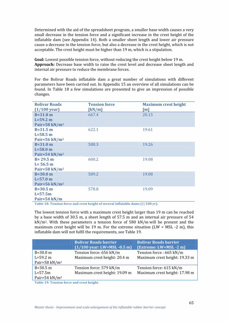
65 Master thesis - Improvement and scale enlargement of the inflatable rubber barrier concept
Determined with the aid of the spreadsheet program, a smaller base width causes a very small decrease in the tension force and a significant increase in the crest height of the inflatable dam (see Appendix 14). Both a smaller sheet length and lower air pressure cause a decrease in the tension force, but also a decrease in the crest height, which is not acceptable. The crest height must be higher than 19 m, which is a stipulation. Goal: Lowest possible tension force, without reducing the crest height below 19 m. Approach: Decrease base width to raise the crest level and decrease sheet length and internal air pressure to reduce the membrane forces. For the Bolivar Roads inflatable dam a great number of simulations with different parameters have been carried out. In Appendix 15 an overview of all simulations can be found. In Table 18 a few simulations are presented to give an impression of possible changes. Bolivar Roads (1/100 year)
Tension force [kN/m]
Maximum crest height [m]
B=31.8 m L=59.2 m Pair=58 kN/m2
667.4 20.15
B=31.5 m L=58.5 m Pair=56 kN/m2
622.1 19.61
B=31.0 m L=58.0 m Pair=54 kN/m2
588.3 19.26
B= 29.5 m L= 56.5 m Pair=58 kN/m2
600.2 19.08
B=30.0 m L=57.0 m Pair=56 kN/m2
589.2 19.08
B=30.5 m L=57.5m Pair=54 kN/m
578.8 19.09
Table 18: Tension force and crest height of several inflatable dams (1/100 yr).
The lowest tension force with a maximum crest height larger than 19 m can be reached by a base width of 30.5 m, a sheet length of 57.5 m and an internal air pressure of 54 kN/m2. With these parameters a tension force of 580 kN/m will be present and the maximum crest height will be 19 m. For the extreme situation (LW = MSL -2 m), this inflatable dam will not fulfil the requirements, see Table 19.
Bolivar Roads barrier (1/100 year: LW=MSL -0.5 m)
Bolivar Roads barrier (Extreme: LW=MSL -2 m)
B=30.0 m L=59.2 m Pair=58 kN/m2
Tension force: 656 kN/m Maximum crest height: 20.4 m
Tension force : 665 kN/m Maximum crest height: 19.33 m
B=30.5 m L=57.5m Pair=54 kN/m2
Tension force: 579 kN/m Maximum crest height: 19.09 m
Tension force: 615 kN/m Maximum crest height: 17.98 m
Table 19: Tension force and crest height.

66 Master thesis - Improvement and scale enlargement of the inflatable rubber barrier concept
For this research it is assumed that the extreme situation must be respected, and as a result a base width of 30.0 m, a sheet length of 59.2 m and an internal air pressure of 58 kN/m2 will be applied for the Bolivar Roads barrier. The maximum tension force will be 665 kN/m. In Table 20 the membrane, vertical and horizontal forces of the Bolivar Roads barrier with these parameters are shown.
B=30.0 m L=59.2 m Pair=58 kN/m2
Bolivar Roads barrier (1/100 yr)
Bolivar Roads barrier (LW= MSL -2m)
Membrane force (T) [kN/m] 656 665 Vertical clamping forces (RVa) [kN/m] 460 319 Vertical clamping forces (RVb) [kN/m] 515 482 Horizontal clamping forces (RHa) [kN/m] 467 583 Horizontal clamping forces (RHb) [kN/m] 407 458 Table 20: Membrane, vertical and horizontal forces of Bolivar Roads barrier.
In case a barrier is chosen as indicated with the yellow line in Figure 55 of paragraph 5.1, the maximum depth of the water will be 12 m below MSL. With a maximum upstream water level of MSL +5 m an inflatable dam with a crest height of 17 m is needed. With a minimum downstream water level of MSL -0.5 m a tension force of 500 kN/m might occur in the sheet. When the location of the barrier is chosen more seawards, an inflatable dam with a crest height of ‘only’ 16 m is needed, which results in an even lower membrane force than 500 kN/m. For this research the inflatable dam with a crest height of 19 m will be studied in more detail, because this is the most challenging situation due to the large depth.
7.2.4 Material of the sheet From the previous paragraph it is clear that the membrane forces of the Bolivar Roads barrier are much higher compared to the Ramspol barrier. The material of the sheet should be made strong enough to resist these forces. The strength of the sheet is dependent on the reinforcement materials and its thickness. To increase the strength of the sheet more and/or stronger reinforcement layers can be applied. Unfortunately, stronger materials have in general a higher stiffness, which causes higher dynamic forces and peak stresses. Also a higher stiffness might lead to storing problems of the sheet. The total design load for the Bolivar Roads barrier is initially calculated with the discussed design formula of Ramspol (paragraph 3.7). The calculated sheet strength using this formula results in a minimum of 3085 kN/m. Reinforced rubber sheets with high strengths are developed and used for conveyor belts. In the reference study more information about conveyor belts of Dunlop is given. A comparison between an inflatable dam sheet and a conveyor belt is made to indicate that materials which can withstand very high loads are already existing and in use. Recently, Dunlop has developed a rubber sheet (Superfort® conveyor belt with 7 plies) with a tensile strength of approximately 4000 kN/m.21 What the remaining strength will be after fatigue loading, ageing and relaxation from pre-stress conditions is not yet studied. Dunlop expects that the remaining strength is large enough to resist a load larger than 3085 kN/m. Obvious, a similar sheet material like the Superfort® conveyor belt of Dunlop could be applied for the sheet of the inflatable dams of Bolivar Roads. The total carcass thickness of the 7 plies of the Superfort® conveyor belt is 16 mm, which is 5 mm thicker compared to the carcass of the Ramspol sheet (11 mm).
21 Jeroen Kattouw - Application Engineer by Dunlop

67 Master thesis - Improvement and scale enlargement of the inflatable rubber barrier concept
The cover thickness of the Superfort® conveyor belt is 4 mm for the top and 2 mm for the bottom. For the barrier a top thickness of 3 mm (as used for Ramspol) might also be sufficient. The strain stiffness is also higher than that of the sheet of Ramspol. A much higher stiffness might cause larger dynamic forces and stress concentrations in the sheet above the abutments. This was also the case for the initial selected Kevlar® reinforcement for the Ramspol sheet; from test results it appeared that such Kevlar® reinforcement was too stiff and, hence, was replaced by a less stiff nylon reinforcement. Although the carcass thickness of the Superfort® conveyor is thicker compared to Ramspol, the stiffness of this belt is much smaller than the stiffness of the initial selected Kevlar® sheet. An explanation for this phenomenon is that the Superfort® conveyor belt consists of synthetic EP (polyester-nylon) fabric plies. In Table 21 it can be seen that the elongation at breakpoint is much smaller for Kevlar® than for nylon. Because the Superfort® sheet consist of polyester-nylon, it is assumed that the stiffness will not cause an increase of the dynamic forces and the stress concentrations in the sheet above the abutments.
Material Elongation at break [%]
Nylon/ Polyamide 20
Kevlar 3 – 4 Table 21: Elongation at break (Naeff 2009).
The strength of 3085 kN/m comprises of the calculation with the Ramspol design formula. Some factors in this formula might need to be changed for the Bolivar Roads situation. At the end of this chapter it will be examined which factors need adaption.
7.2.5 Resonance and sloshing For the inflatable dam of Bolivar Roads it must be checked if problems, like resonance and sloshing, will occur. For the time-being a simple comparison with the inflatable dam of Ramspol is made to check these problems. Resonance A strong resonance can occur when the wave frequencies are near the frequencies of the inflatable dam (through amplification). To prevent resonance, it is advantageous that the lowest natural frequencies of the dam are much higher than the wave frequencies. For an increasing movement of the dam the excitation must be periodic. In case of irregular waves, which is common, the development of the movement of the dam will be disturbed and resonant rise will not occur easily. For the dam of Ramspol no problems with resonance are detected. Because the dam of Bolivar Roads has an equal or larger stiffness than the dam of Ramspol and waves are in most cases irregular, it is assumed that resonance will not be an issue for the Bolivar Roads dam. Sloshing The sloshing wave height inside the inflatable dam will decrease by an increasing internal water mass. Therefore, a larger internal water level will be favourable to prevent sloshing. An associated explanation is that how larger the internal water level, how larger the height related to the width, more water mass will be moved rigid and thus less sloshing. The height/width ratio of internal water of the Bolivar Roads barrier ( ) is larger than the height/width ratio of the Ramspol barrier ( ). Because the Ramspol barrier has no problems with sloshing, it is assumed that sloshing will also not be an issue for the Bolivar Roads barrier. With a lower downstream water level the sloshing wave height will also decrease, because the stiffness of an inflatable dam will be larger. Therefore, it is concluded that for the extreme situation (LW=MSL -2 m) sloshing also will not be a problem.

68 Master thesis - Improvement and scale enlargement of the inflatable rubber barrier concept
7.3 Improve the geometry of the abutments In the preliminary investigation it is concluded that the inflated barrier of Ramspol has fold formation above the abutments and peak stresses in the sheet due to these folds (paragraph 3.6). These folds and peak stresses are dependent on the geometry of the abutments and connection to the abutments. For the barrier of Bolivar Roads these folds and peak stresses in the sheet must be avoided. In this paragraph the geometry of the abutments and the connection to the abutments is optimized to prevent fold forming.
§ 7.3Improve geometry of abutments
§ 7.3.1Cause folds and peak
stresses
§ 7.3.2Decrease folds and
peak stresses
§ 7.3.3New design: Ellipsoid
bellows-dam
§ 7.3.4Dimensions
§ 7.3.5Bed protection
Figure 69: Overview paragraph 7.3.
In the first subsection of this paragraph the origin of the folds and peak stresses are discussed in more detail. After defining the origin, solutions will be developed in the second subsection to decrease the folds and peak stresses. The third subsection will show a new design of the inflatable dam, which is expected to have less folds and peak stresses than the dam of Ramspol. In the fourth subsection the dimensions of the inflatable dams and abutments of Bolivar Roads are presented. The last subsection will discuss the bed protection that is needed for Bolivar Roads barrier.
7.3.1 Cause of folds and peak stresses Due to the connection of the inflatable dam with the abutments, an enlargement of the sheet (overlength) is necessary in two directions:
The sheet dimensions must be sufficient to store the sheet properly in the bottom recess and in the recesses of the abutments.
At the location of the transition to the abutments the inflatable dam must have enough freedom of movement (i.e. leeway) to prevent transfer of forces in longitudinal direction towards the abutments, see Figure 70.
Figure 70: Shifting of the inflatable dam.
This overlength of several meters presents a problem when clamping the sheet, see Figure 71; the clamping line on the abutment has a limited length of L (m) and the sheet length that needs to be clamped is 1.27 times longer. To overcome this problem the clamping line should be made longer.

69 Master thesis - Improvement and scale enlargement of the inflatable rubber barrier concept
Figure 71: Design of abutment Ramspol (edge of membrane: sheet lies flat on the bottom).
For the Ramspol barrier the clamping lines on the abutments are constructed stepwise in a wavy form, as discussed in paragraph 3.6. This modification of the sheet clamping structure implies an enlargement of the total clamping length along the steps of the abutment. Unfortunately, the double waved clamping structure on the abutment causes many forced strains and stresses in the sheet. Figure 72 shows the difference between a straight clamping line and a wavy-formed clamping line.
Figure 72: Overlength; Left: straight clamping line, Right: wavy formed clamping line.
The length of the straight clamping line equals √ . When the slope of the abutments is smaller than 45 degrees, a larger overlength of the sheet can be clamped. A smaller slope can only be created by a larger width (b) of the abutment. A wavy-formed clamping line results in a larger length compared to a straight line. With
a wavy-formed clamping line the length will be
instead of for a
straight line. The overlength of the sheet in longitudinal direction will also cause folds and peak stresses around the transition between the middle section and abutments when the inflatable dam is inflated. Normally, when the dam is uniformly loaded in longitudinal direction the load will be transferred in the circumference direction of the dam to the clamping lines of the sheet and foundation floor. At the parts where the normal force is not evenly distributed to the clamping line, like e.g. the angled transition to the abutments and the wavy-formed clamping on the abutments, considerable stress concentrations in the sheet might occur. In Figure 73 (next page) the tension forces in the sheet due to two different stepwise clamping methods (large and small steps) on the abutments are shown. The sheet stresses around the clamping structure are higher than the stresses above the transition between the horizontal and sloping part, but covers a smaller area. In the left picture of Figure 73 it can be seen that much stronger forces in the sheet occur around the clamping line.

70 Master thesis - Improvement and scale enlargement of the inflatable rubber barrier concept
Figure 73: Tension force in transverse direction; Left: large steps, Right: waves (Rijkswaterstaat).
In Figure 74 the tension forces in the sheet around the wave clamping structure are shown. With the wave clamping structure high tension forces are still present around the clamping line compared to the rest of the sheet.
Figure 74: Forces in longitudinal direction; wave clamping structure (Bouwdienst Rijkswaterstaat).
For the inflatable dam of Bolivar Roads such considerable stress concentrations in the sheet should be avoided. To decrease these sheet stresses the overlength of the sheet should be minimized. Hereby, it is important that the two functions of the overlength are not disturbed. An alternative way to decrease sheet stresses is another way of clamping.
7.3.2 Minimize overlength without disturbing storage and freedom of movement In this subsection it is studied how the overlength can be decreased, without disturbing the storing of the sheet in the bottom recess and the freedom of movement of the inflatable dam at the location of the transition to the abutments. A smaller angle slope of the abutment increases the length of the clamping line, and thus decreases the overlength. Therefore, a smooth transition (without a deep kink) reduces peak stresses in the sheet around the transition to the abutment.

71 Master thesis - Improvement and scale enlargement of the inflatable rubber barrier concept
In Figure 75 a side view of an inflatable dam with two different slope angles of the abutments is given. One abutment has a 1:1 slope and the other abutment has a less steep slope.
Figure 75: Different slopes. Left: side view; Right: top view sheet.
Because the sheet must be stored in the bottom recess, some overlength of the sheet above the abutments must be available. The minimum overlength for the less steep slope is: 8.9 m - 8.2 m = 0.7 m and for the 1:1 slope: 5.7m – 4.5 m = 1.2 m.
In Figure 75 it is also visible that with a less steep slope a larger angle between the horizontal and sloping part of the topside of the inflatable dam is available ( compared to ), which results in less folds. The fold formation and the stresses for a steep abutment is clearly visible in Figure 76.
Figure 76: Stresses in the sheet. Left: slope of the abutment 45 ; Right: slope of the abutment 75 .
Although the overlength can be decreased with a smaller slope of the abutment, some overlength is still present. A way to clamp this overlength without causing folds and peak stresses can be performed via circular clamping lines instead of straight lines, see Figure 77.
Figure 77: Circular clamping lines.

72 Master thesis - Improvement and scale enlargement of the inflatable rubber barrier concept
With circular clamping lines the unique shape of a zeppelin/Yokohama fender can be used for the shape of the inflatable dam. This results in a half ellipsoid, cut longitudinal and attached to the abutments, see Figure 78. The middle part of the dam is like a ‘normally’ shaped inflatable dam, i.e. half cylindrical.
Figure 78: A half ellipsoid-shaped inflatable dam attached to the abutments.
In the following subsection this ellipsoid-shaped inflatable dam is discussed in more detail and it is attempted to proof qualitatively that this design leads to less folds and peak stresses than the dam of Ramspol.
7.3.3 Ellipsoid inflatable dam for the Bolivar Roads An ellipsoid-shaped inflatable dam has, related to the inflatable dam of Ramspol, the advantage that no large folds will occur at the transition between the middle section and the abutments, see Figure 79.
Figure 79: Left: folds at transition; Right: no folds at transition.
Because for the ellipsoid shape of the inflatable dam no folds occur at the location of the kinked transition, the normal force can be evenly distributed to the clamping line, see Figure 80. With this information it can be concluded that almost no considerable stress concentrations will occur in the sheet around the kinked transition.
Figure 80: No stress concentrations at the transition between the middle section and abutments.
An ellipsoid-shaped dam has, compared to the dam of Ramspol, also the advantage that no small folds will occur around the clamping line, because no double waved clamping structure is needed (a double waved clamping structure causes many forced strains in the sheet). Since there is no overlength needed for an ellipsoid-shaped dam, the clamping structure on the abutments can be the same as for the middle section.

73 Master thesis - Improvement and scale enlargement of the inflatable rubber barrier concept
Due to the absence of the double waved clamping structure it is concluded that almost no considerable stress concentrations will occur in the sheet around the clamping line. The advantage of an ellipsoid-shaped inflatable dam is clear, but it is still open whether the dam has enough freedom of movement at the transition to the abutments and whether the sheet can be stored properly. When the inflatable dam of Bolivar Roads is loaded at a head difference of 7 m, a sideward deflection of 8 m and a downward deflection of 1 m might occur due to the hydrostatic water pressure, see Figure 81. The deformation due to waves is disregarded.
Figure 81: Minimum desired freedom of movement, 1: without deformation, 2: with deformation.
According to the theory there will be no load transfer to the abutments when this deformation is also possible around the abutments. Because of the great sheet length above the abutments the extra length needed for this deformation is relatively small. In Figure 82 an example of the deformation of the ellipsoid-shaped inflatable dam is shown. In this example a sheet length above the abutment of 34.4 m (red line in right picture) is taken.
Figure 82: Deformation of the inflatable dam.
Due to the deformation of the dam the chord length of 29.3 m should increase to 30 m. Due to the ellipsoid-shaped dam there is enough length above the abutment to allow this deformation. Only the shape of the ellipsoid will change slightly, see Figure 83.
Figure 83: Cross section; Left: without deflection, Right: with deflection.

74 Master thesis - Improvement and scale enlargement of the inflatable rubber barrier concept
It is assumed that the shape of the ellipsoid can change enough to enable this lateral movement without much extra stresses in the sheet. When wave loads are taken into account a larger lateral movement than 8 m will occur. For example, with a lateral movement of 11 m the chord length of 29.3 m should increase to 31 m, which is also possible. Another option is to increase the curvature of the ellipsoid-shaped inflatable dam, which increases the sheet length above the abutments (> 34.4 m). The lateral movement caused by waves is definitely possible with limited force transfer to the abutments. Therefore, it can be concluded that an ellipsoid-shape inflatable dam allows independent behaviour of the middle and side parts of the dam and will prevent force transfer to the abutments. The sheet dimensions of an ellipsoid-shaped inflatable dam must allow storing in the bottom recess, which can only take place if the crest length of the dam above the abutment (red line in Figure 84) is larger than 29.3 m. Since the green line has already a length of 29.3 m, it can be concluded that the dimensions of the ellipsoid-shaped inflatable dam do allow storing the sheet in the bottom recess. The sheet angle between the ‘chord’ (green line in Figure 84) and the horizontal plane should be the same as the slope of the abutment. With a crest height of 20 m, a 10 meters high attachment point of the end face of the dam with the abutment is needed.
Figure 84: Side view ellipsoid-shaped inflatable dam.
A disadvantage of the ellipsoid-shaped inflatable dam is that water leakage over the abutments might occur, due to the low attachment point of the end face of the dam. Since some water leakage and overtopping is acceptable for the opening of Bolivar Roads, this is not a problem. When no leakage is allowed, a higher attachment of the end face with the abutment should be taken, resulting in a larger crest height of the dam.
7.3.4 Dimensions of the inflatable dams and abutments of Bolivar Roads In the previous paragraphs it was concluded that a smaller slope of the abutment and an ellipsoid shape of the inflatable dam both will reduce the fold formation and peak stresses in the sheet. Also, it could already be concluded that multiple dams over the entire width of the Bolivar Roads, instead of one dam, increase the reliability and is easier for construction and placement purposes. To combine these benefits a design is made with several inflatable dams with a shape of a half ellipsoid over the total width of the estuary, see Figure 85 (next page). Intermediate abutments should be realized to connect the dams. The height of the dams can be varied depending on the depth of the water (from 7.5 m to 19 m high).

75 Master thesis - Improvement and scale enlargement of the inflatable rubber barrier concept
Figure 85: Several inflatable dams over the estuary width using intermediate abutments.
A flat slope of the abutments is advantageous for the storage and peak stresses, but disadvantageous for the water flow, because large abutments are present in the free flow opening. A requirement is that no abutment might be realized in the main channel; the channel width should stay 180 m. With a slope of the abutment of 20 and a bottom length of the dam of minimally 180 m, a minimal intermediate space of 284 m will be present between the abutments:
Ltop =
This value will be rounded off upwards to 300 m, see Figure 86. The dam length in such case is approximately 250 m. The length of the other dams is based on this length.
Figure 86: Inflatable dams with an abutment of 20 .
In Figure 87 a cross-section of the Bolivar Roads barrier with several inflatable dams placed over the entire width is shown. All the abutments have a slope of 20 . The figure gives a distorted view because the depth in reality is much smaller than the width.
Figure 87: Bolivar Roads barrier consisting of 7 inflatable dams, abutment slope of 20 .
In this design the barrier of Bolivar Roads consists of seven inflatable dams, each with a length of 250 m. One dam has a crest height of 19 m, three dams have a crest height of 17 m and three dams have a crest height of 10 m. The foot level of the dam is chosen on the basis of similarity and the depth profile to reduce excavation works.

76 Master thesis - Improvement and scale enlargement of the inflatable rubber barrier concept
The dimensions of the inflatable dam which are shown in Figure 87 should fulfil the following two requirements: The first technical requirement is that maximally 40% of the opening (13108.6 m2) may be permanently closed. Therefore, the total area of the intermediate abutments must be lower than 40%. When the horizontal part of the abutment (top) has a width of 10 m, the area of the abutments minus the pink parts will be approximately 3000 m2. See Appendix 16.1 for the exact calculation.
With this geometry 23% of the opening is permanently closed, which is beneath the requirement of 40%. The second technical requirement for this barrier is that during a storm surge maximally 25%22 of the opening (25608.6 m2) is allowed to remain open. It is important that failure of the largest inflatable dam will not lead to exceedance of the requirement of 25%. In this design failure of the largest dam will lead to a water leakage less than 20%. This is still within the 25% requirement range.
A higher reliability can be obtained by a smaller length of the inflatable dam. With a such smaller length a collapse of one dam will result in a smaller water leakage percentage and thus a smaller release of water downstream. A disadvantage of a smaller dam length is the requirement for more abutments, which is not wanted. Unfortunately, the biggest dam cannot be split into two or more dams, because no abutment may be realized in the main channel. The smaller dams can be split into more dams (see Figure 88), as long as the technical requirement of maximally 40% of the opening that may be permanently closed is satisfied.
Figure 88: Several inflatable dams realized over Bolivar Roads with intermediate abutments.
Research has been done by Ruijs23 in order to investigate what the influence is of a storm surge barrier located at Bolivar Roads on the water discharge and velocity. With a combination of a floating sector gate barrier and vertical lifting gates built in the Bolivar Roads inlet, it is expected that the flow area will be permanently decreased with 40-60%. This flow area reduction can cause an increase in water velocity. For the IRB this area reduction is only 23%.
22 This percentage is an assumption and it might be good possible that a smaller area than 25% of the inlet may stay open. In that case, a smaller value than 25% is preferred. 23 Ruijs, M., The effects of the “Ike Dike” barriers on Galveston Bay, TU Delft, June 2011.

77 Master thesis - Improvement and scale enlargement of the inflatable rubber barrier concept
In the research of Ruijs alternatives are schematized in a way that the flow area of the barriers are 100%, 80%, 60%, 40% or 20% of the initial flow area of the inlet. In Figure 89 the influence on the maximum current speed of the flow due to the decrease in the flow area is given.
Figure 89: Maximum occurring current speed at the Bolivar Roads inlet (Ruijs).
According to the research of Ruijs an increase in the current speed near the barriers can only be found due to the constriction of the flow area, in the remainder of the bay the current speeds decreases. An increase in the current speed can be found for a decrease in the flow area up to 40% of the original flow area. When the Bolivar Roads inlet is constricted further, the tidal prism decreases in such a way that also the current speeds will decrease. With a constriction of 23% the current speed is increasing from 1 m/s to 1.5 m/s. Between and around the inflatable dam a bottom protection is necessary. The length of the protection is dependent on the water velocity at the river bed.
7.3.5 Bed protection The abutments of the barrier placed in the opening result in a reduction of the flow area. This reduction can cause an increase in water velocity at the sea bed. Sediments that usually rest on the sea floor can be transported to another area of the bay as a result of the increasing velocities. Bottom scour may affect the waves in front of the structure and can lead to gradual dislocation of the soil and can decrease the geotechnical stability of the bottom recess. In the main channel sediment transportation might also occur due to ship movements. To reduce such risk, a bed protection should be constructed. When the inflatable dam is deflated, the intermediate abutments will reduce the flow area from 13108.6 m2 to 10108.6 m2. The velocity on the sea floor due to currents and tides normally is 0.053 m/s24. The flow rate equation can be used to determine the change in velocity on the sea floor due to tides and currents as a result of the change in area. The flow rate Q is assumed to stay constant before and after the barrier is in place.
24 Cox, C., Davis, J., Hennigan, S. and Robichaux, L., Bolivar Roads Sector Gates, April 2013.

78 Master thesis - Improvement and scale enlargement of the inflatable rubber barrier concept
The resulting velocity due to currents and tides is 0.069 m/s. The geometry of the intermediate abutments should be set as fixed boundaries to calculate the new wave conditions. The airy wave theory (Appendix 16.2) can be used to find the changed velocity on the sea floor level due to waves. This new velocity can be added to 0.069 m/s to find the total bottom velocity after the structure is placed. It is assumed that the final velocity on the sea floor will be not more than 0.11 m/s25. With the following formula: , a grain size diameter of 0.000245 cm is calculated. Because the grain size diameter is still lower than the size fraction of sand (0.00635 cm versus 0.20066 cm) none of the sediment is expected to be transported due to increased velocities on the sea bed due to intermediate abutments. In the inflated state of the inflatable dam some water will flow over the ends with a large velocity. Waves might also overtop the dam. The velocity of the water that flows over the dam and the abutments is much larger than the 1.5 m/s present due to a constriction of 23%. When water waves flow over the inflated dam the overtopping water often follows the curve of the dam to the bottom. The plunging jet dives to the bottom and might affect a small area of the bed protection directly behind the dam, see Figure 90.
Figure 90: Plunging jet.
The downstream bottom side is than loaded by a downward directed flow. This type of load can be significantly heavier than the load that arises due to a flow parallel to the ground (open barrier). Because non-erosion resistant soil is present for the Bolivar Roads, the bed must be protected. The bed protection has different functions:
Keeping enough distance between the scour hole on both sides of the barrier; Preventing erosion under the barrier when the dams are inflated and a large
head difference exists across the barrier with a large gradient in the filter; Protecting the bottom recess near the dam when large velocities occur through
the openings during inflation or when all dams are inflated except for one. With these functions in mind, a bed protection consisting of concrete block mattresses, filter mattresses and placed large rocks and concrete blocks can be created. The bottom protection for Bolivar Roads is based on the bottom protection of the Eastern Scheldt estuary in Zeeland, the Netherlands. On both sides of the barrier concrete block mattresses, with an assumed length of 300 m should be applied. These mattresses have to withstand the turbulent flow. Concrete blocks are attached to a layer of geotextile with plastic pins in order to make the mattresses sink and to ensure the stability of the mattresses at the bottom, see Figure 91. After sinking, the mattresses should be covered with steel slags for more stability in the turbulent currents.
25 Cox, C., Davis, J., Hennigan, S. and Robichaux, L., Bolivar Roads Sector Gates, April 2013.

79 Master thesis - Improvement and scale enlargement of the inflatable rubber barrier concept
Figure 91: Composition concrete block mattress Eastern Scheldt, the Netherlands.
Under the barrier a large gradient parallel to the bed might be active. Therefore, under the barrier a filter mattress, like a geometrically closed granular filter, should be constructed yet is complicated and very expensive. Therefore, a combination can be made of a geometrically closed granular filter and geotextiles, see Figure 92.
Figure 92: Composition filter mattress Eastern Scheldt.
The geotextile wraps the filter grains and thus enables to bring the thin layers of fine material to the bottom in such a way that the integrity of the filter structure remains intact. When the geotextile eventually deteriorates, the geometrically closed granular filter is right in place.
Figure 93: Cross-section barrier foundation Eastern Scheldt.
In order to protect the foundation of the barrier, large rocks and concrete blocks should be placed. An indication of the placed rocks and concrete blocks is given in Figure 93 and Figure 94.
Figure 94: Top view bottom protection barrier Eastern Scheldt.

80 Master thesis - Improvement and scale enlargement of the inflatable rubber barrier concept
7.4 Improving the storage of the sheet When an inflatable dam is deflated, the sheet must lie stable on the river bed or in a bottom recess. Without a bottom recess it is very hard to keep the sheet stable on the river bed. Therefore, a bottom recess is chosen for the storage of the sheet of the Bolivar Roads barrier. From the preliminary investigation it was revealed that the barrier of Ramspol has sometimes problems with the storage of the sheet, like flap occurring (paragraph 3.5). Therefore, the design of Ramspol should be improved for the Bolivar Roads barrier to avoid these problems.
§ 7.4Improving the storage of the sheet
§ 7.4.1Options to improve storing
§ 7.4.2Bottom recess Bolivar Roads
§ 7.4.3Measurements to improve storing
Figure 95: Overview paragraph 7.4.
The first subsection of this paragraph will discuss the options available to improve the storing of the sheet in a bottom recess with rollers in general. With these options in mind, an improved design for the storage of the sheet for Bolivar Roads is developed which is described in the second subsection. The last subsection discusses the measurers that can be taken in order to improve the storing of the sheet and to monitor whether the sheet is well-distributed over the rollers.
7.4.1 Options to improve sheet storing In order to improve the storage of the sheet it is very important that friction should be kept minimal. The rollers should be executed with bearings to minimize the friction when the sheet moves in transverse direction. The following options can be applied in order to improve sheet storing:
A small number of roller rows; No contact with floor or less friction of the floor by e.g. an Ultra High Molecular
Weight Polyethylene (UHMWPE) layer; Larger diameter of the rollers; A more equal shape of the stored sheet; Blowing more air off.
A small number of roller rows From previous test results it was concluded that a small number of rollers in the bottom recess leads to the least stowing trouble. Therefore, a small number of roller rows should be chosen, though unfortunately increasing the depth of the bottom recess. No contact or less friction with the floor The friction between the sheet and the floor of the bottom recess determines whether the sheet can be redistributed. For an optimal redistribution of the sheet, it should not experience strong friction forces when it is moving in transverse direction. The best design would be one whereby floor contact of the sheet is prevented. Another option is to decrease the friction of the floor with e.g. a low-friction UHMWPE layer. UHMWPE has high wear-resistant properties (even greater than steel), low maintenance costs and can be fastened to concrete easily.
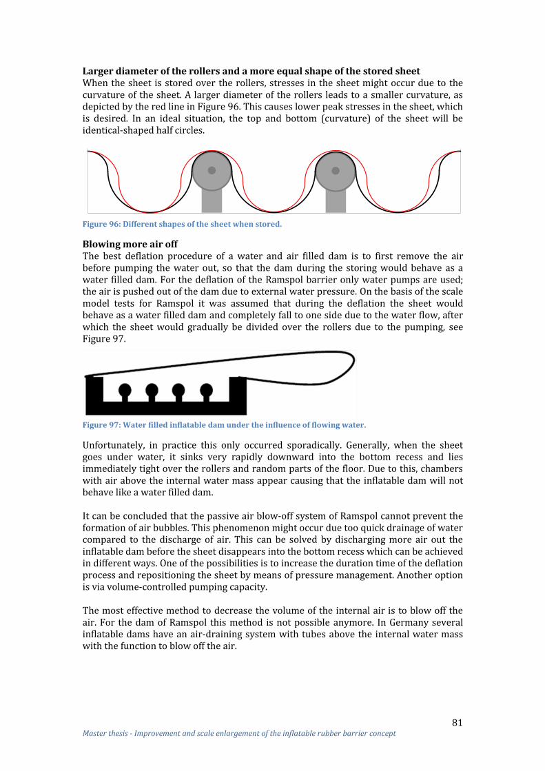
81 Master thesis - Improvement and scale enlargement of the inflatable rubber barrier concept
Larger diameter of the rollers and a more equal shape of the stored sheet When the sheet is stored over the rollers, stresses in the sheet might occur due to the curvature of the sheet. A larger diameter of the rollers leads to a smaller curvature, as depicted by the red line in Figure 96. This causes lower peak stresses in the sheet, which is desired. In an ideal situation, the top and bottom (curvature) of the sheet will be identical-shaped half circles.
Figure 96: Different shapes of the sheet when stored.
Blowing more air off The best deflation procedure of a water and air filled dam is to first remove the air before pumping the water out, so that the dam during the storing would behave as a water filled dam. For the deflation of the Ramspol barrier only water pumps are used; the air is pushed out of the dam due to external water pressure. On the basis of the scale model tests for Ramspol it was assumed that during the deflation the sheet would behave as a water filled dam and completely fall to one side due to the water flow, after which the sheet would gradually be divided over the rollers due to the pumping, see Figure 97.
Figure 97: Water filled inflatable dam under the influence of flowing water.
Unfortunately, in practice this only occurred sporadically. Generally, when the sheet goes under water, it sinks very rapidly downward into the bottom recess and lies immediately tight over the rollers and random parts of the floor. Due to this, chambers with air above the internal water mass appear causing that the inflatable dam will not behave like a water filled dam. It can be concluded that the passive air blow-off system of Ramspol cannot prevent the formation of air bubbles. This phenomenon might occur due too quick drainage of water compared to the discharge of air. This can be solved by discharging more air out the inflatable dam before the sheet disappears into the bottom recess which can be achieved in different ways. One of the possibilities is to increase the duration time of the deflation process and repositioning the sheet by means of pressure management. Another option is via volume-controlled pumping capacity. The most effective method to decrease the volume of the internal air is to blow off the air. For the dam of Ramspol this method is not possible anymore. In Germany several inflatable dams have an air-draining system with tubes above the internal water mass with the function to blow off the air.

82 Master thesis - Improvement and scale enlargement of the inflatable rubber barrier concept
In Figure 98 a scale model is shown where tubes ensure the connection between the internal air and the outside atmosphere.
Figure 98: A part of an inflatable dam with an internal tube for pumping air out.
Placement of such tubes every 5 meter might be needed for a good deflation process. These tubes ensure that first all the air is relieved, leading to the result that the inflatable dam behaves like a water filled dam. A disadvantage of these tubes is that it decreases the flexibility of the sheet, which might cause problems concerning storing.
7.4.2 Bottom recess of Bolivar Roads barrier Considering the concluded options of the previous paragraph, there is tried to develop an optimal design for the storage of the sheet of Bolivar Roads. The largest inflatable dam of the Bolivar Roads barrier has a bottom recess with a width of 30 m in which a sheet with a circumferential length of approximately 60 m should be stored. When the sheet has, in stored position, the shape of equal half circles and the bottom recess has a width of 30 m, the diameter of the rollers can be found with the following formula: With 2 roller rows a maximum roller diameter of 5 meter (r = 2.5 m) can be applied and with 3 roller rows a maximum diameter of 3.75 m (r = 1.875 m). An extra vertical length (x) is needed to store the 60 meters sheet, see Figure 99.
Figure 99: Extra depth of bottom recess needed.

83 Master thesis - Improvement and scale enlargement of the inflatable rubber barrier concept
The extra needed length can be calculated by using the following formula: With 2 roller rows an extra length of 2.15 m is needed and with 3 roller rows an extra length of 1.4 m is required. The depth of the bottom recess depends on the diameter of the rollers and on the extra length (x). The depth of the bottom recess can be calculated with the following formula: With 2 roller rows a depth of 7.15 m is needed and with 3 roller rows a depth of 5.15 m. Three roller rows with each a diameter of 3.75 m have been chosen. Thus, the depth of the bottom recess should be 5.15 m. A roller with a diameter of 3.75 m is very large; thereby, a steel roller as used for Ramspol is not an option. Instead of a steel roller, big tires can be applied, as e.g. used for tar sand trucks, see Figure 100.
Figure 100: Tire of a tar sand truck.
Three rows of tires with a distance of 7.5 m between each row can be placed in the bottom recess, see Figure 101. For another storage possibility see Appendix 16.3.
Figure 101: Part of the bottom recess with three rows of tires.
At each row several tires with a diameter of 3.75 m are placed close to each other (with a distance of approximately 1 m). The width of such a tire can be around 1.5 m. The distance of 1 m between the tires is enough to prevent that the sheet will touch the support, see Figure 102. It is still important that the supports – which held the tires in place – have no sharp edges. Also the rollers should not be affected by water and sediment. Sediment can be kept out of the inflatable dam by filtering the water flowing into the dam.

84 Master thesis - Improvement and scale enlargement of the inflatable rubber barrier concept
Figure 102: Distance between the tires.
In the previous paragraph it was concluded that it is important for the storing process that first all the internal air is blown off before the water is pumped out. This can be realized with a tube system inside the inflatable dam. It is very important that the tubes and the inner side of the sheet are intertwined with each other in such a way that no damage to the tubes can occur due to the tires. The tubes attached to the sheet might decrease the flexibility of the sheet, but because of the large diameter of the rollers this should not be a problem. The storing of the sheet in the bottom recess on the abutment will be different than in the middle section. In longitudinal direction the maximum length of the ellipsoid sheet above the abutment (C-A) is e.g. 34.4 m with a chord length of 29.3 m, see Figure 103. Due to this maximum length, the sheet cannot further sag in deflated state than the yellow line in this figure. The deflated sheet is probably located between the orange and yellow line.
Figure 103: Deflation of the inflatable dam.
In the bottom recess of the horizontal section 3 roller rows are present which end at the point where the horizontal part goes over in the slope of the abutment. In the abutment recess no rollers are situated. Figure 104 shows that the sheet length in longitudinal direction should be large enough to store the sheet properly.
Figure 104: Left: inflated dam; Right: cross-section deflated dam.

85 Master thesis - Improvement and scale enlargement of the inflatable rubber barrier concept
In the left figure colour lines are drawn over the inflated dam corresponding with the lines in the right figure showing how the sheet is distributed over the rollers in the transition zone. From this figure it can be seen that the green line must have the largest length of all lines in order to store the sheet properly. The required length of this line is at least 33.5 m. With the given dimensions, the blue line (clamping line) in the figure has a length of approximately 36.5 m and the red line a length of approximately 34.4 m. The length of the intermediate lines of the inflated dam lies between these values. Because all the lines have a larger length than 33.5 m, it is concluded that the sheet can be folded over the rollers in the transition zone. When the sheet is stored, sediment might sink in the trenches due to smaller flow velocities. This sediment will lie down on the sheet, which might result in inflation problems due to a larger weight. The situation for the barrier of Ramspol is also similar, but no problems with the inflation due to the extra weight of sediment have been observed. This is because only 2 mbar is needed to raise the sheet and 300 mbar is the available pressure. The needed pressure to raise the sheet loaded with sediment is much lower than 300 mbar. Therefore, it is concluded that sediment will not be a problem for the inflation of the dams of Bolivar Roads.
7.4.3 Measurements to improve sheet storing For Ramspol underwater inspections (by a diver) are performed to check whether folds are present when the sheet is stored. When folds are present, pressure management (deflation of the sheet in two phases) will be applied in order to remove the folds. This pressure management is a very effective measure in order to prevent (extremely) large folds, and to remove folds in general. For the storage of the sheet of the inflatable dam of Bolivar Roads this pressure management is an absolute necessity. Because of the large length of the Bolivar Roads barrier it is a poor solution to check the sheet using a diver if folds are present. A more suitable solution is to measure with the use of sensors whether the sheet is distributed well over the rollers. It is hardly possible to accurately monitor with sonar equipment whether the sheet is stored right. The sonar measures only the bottom recess with rotating roller and not the sheet itself. Therefore, in the sheet some transponders as e.g. used for animal identification should be embedded to enable position detection with sensors. Those transponders should be applied at each top and trench of the sheet in cross-sectional direction extended in longitudinal direction every e.g. 5 meter, see Figure 105.
Figure 105: Preferred location of the transponders.
With the sensor it can be detected whether the sheet is well distributed over the rollers and if any folds are present. With a computer the shape of the deflated sheet can be simulated and a warning can be given when the sheet is not distributed over the rollers as desired. When folds are measured, pressure management should be applied in order to remove these folds.

86 Master thesis - Improvement and scale enlargement of the inflatable rubber barrier concept
7.5 Summary of design 1 for Bolivar Roads In this paragraph the final design as discussed in this chapter is summarized. In this design, the barrier of Bolivar Roads consists of multiple chained inflatable dams realized over Bolivar Roads; the original concept of Ramspol is maintained, with the result that the inflatable dams of Bolivar Roads have connections with the abutments. The barrier of Bolivar Roads consists of 7 inflatable dams, each with an approximate length of 250 m:
3 dam with a crest height of 10 m 3 dam with a crest height of 17 m 1 dam with a crest height of 19 m
Figure 106: Bottom profile with proposed dimensions of the inflatable dam.
A smaller length of the inflatable dams will increase the reliability and ease of construction. Unfortunately, a smaller length of these dams will lead to abutments in the navigation channel, which is not desired. The inflatable dam situated in the navigation channel of Bolivar Roads has a larger crest height compared to the dams situated outside this channel. Therefore, only this dam was investigated for 2-D scale enlargement. The following parameters of this dam are calculated:
Height: 19 m; Base width: 30.0 m; Sheet length: 59.2 m; Internal air pressure: 58 kN/m2.
With an upstream water level of 19 m and a downstream water level of 12 m, a maximum static tension force in the sheet of 665 kN/m will occur.
Figure 107: Clear view of the size proportions of the inflatable dam of Ramspol and Bolivar Roads.
With the design formula of Ramspol the design load will be 3085 kN/m. A reinforced rubber sheet that can resist such a high load is the earlier mentioned conveyor belt of Dunlop; a rubber sheet with seven plies and a tensile strength of approximately 4000 kN/m. The carcass thickness of seven plies is 16 mm, which is 5 mm thicker than the sheet of Ramspol. Because the carcass of this rubber belt is made of polyester-nylon, it is assumed that the stiffness will not cause an increase of the dynamic forces and the stress concentrations.

87 Master thesis - Improvement and scale enlargement of the inflatable rubber barrier concept
To minimize fold formation and peak stresses in the sheet a different design of the abutments and shape of the inflatable dam is made. The first step to decrease folds and peak stresses is to apply a smaller angle of the slope of the abutment (i.e. 20 ). Also, a different shape of the inflatable dam for Bolivar Roads is developed in order to decrease folds and peak stresses, see Figure 108. The dam of Bolivar Roads has the shape of an ellipsoid above the abutment and is half cylindrical in the middle part.
Figure 108: Design 1 Bolivar Roads IRB: ellipsoid-shaped inflatable dams connected to abutments.
An ellipsoid-shaped inflatable dam has, compared to the dam of Ramspol, the advantage that no large folds will occur at the transition between the middle section and abutments. Also, no double-waved clamping structure on the abutment is needed. Due to these advantages it is concluded that almost no or only small folds and peak stresses in the sheet will occur above the abutment and around the clamping line. An optimal design for the storage of the sheet for Bolivar Roads is developed with the following keynotes in mind: a small number of rollers in the bottom recess, a large diameter of the rollers and a more equal shape of the stored sheet. This resulted in a bottom recess with 3 rollers with each a diameter of 3.75 m for the storage of the sheet. To decrease the friction of the floor, the floor will be covered with a low-friction UHMWPE layer. To improve the storing facilities it is important that first all the air in the inflatable dam is blown off, leading to the fact that the dam behaves like a water filled dam. Therefore, several tubes attached to the sheet should be installed inside the dam. It is very important that the tubes and the inner side of the sheet are intertwined with each other, in order that no damage to the tubes can occur due to the rollers. Because the diameter of the rollers is very large a smaller flexibility due to the tubes would not cause problems for the sheet storing. Transponders should be embedded in the sheet allowing to detect, with a sensor, whether the sheet is well-distributed over the rollers and whether any folds are present. When folds are measured, pressure management should be applied in order to remove these folds.
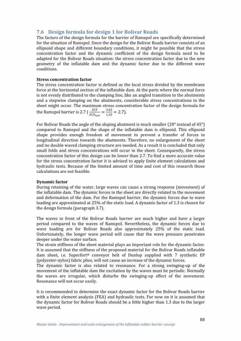
88 Master thesis - Improvement and scale enlargement of the inflatable rubber barrier concept
7.6 Design formula for design 1 for Bolivar Roads The factors of the design formula for the barrier of Ramspol are specifically determined for the situation of Ramspol. Since the design for the Bolivar Roads barrier consists of an ellipsoid shape and different boundary conditions, it might be possible that the stress concentration factor and the dynamic coefficient of the design formula need to be adapted for the Bolivar Roads situation: the stress concentration factor due to the new geometry of the inflatable dam and the dynamic factor due to the different wave conditions. Stress concentration factor The stress concentration factor is defined as the local stress divided by the membrane force at the horizontal section of the inflatable dam. At the parts where the normal force is not evenly distributed to the clamping line, like an angled transition to the abutments and a stepwise clamping on the abutments, considerable stress concentrations in the sheet might occur. The maximum stress concentration factor of the design formula for
the Ramspol barrier is 2.7 (
).
For Bolivar Roads the angle of the sloping abutment is much smaller ( instead of ) compared to Ramspol and the shape of the inflatable dam is ellipsoid. This ellipsoid shape provides enough freedom of movement to prevent a transfer of forces in longitudinal direction towards the abutments. Therefore, no enlargement of the sheet and no double waved clamping structure are needed. As a result it is concluded that only small folds and stress concentrations will occur in the sheet. Consequently, the stress concentration factor of this design can be lower than 2.7. To find a more accurate value for the stress concentration factor it is advised to apply finite element calculations and hydraulic tests. Because of the limited amount of time and cost of this research those calculations are not feasible. Dynamic factor During retaining of the water, large waves can cause a strong response (movement) of the inflatable dam. The dynamic forces in the sheet are directly related to the movement and deformation of the dam. For the Ramspol barrier, the dynamic forces due to wave loading are approximated at 25% of the static load. A dynamic factor of 1.3 is chosen for the design formula (paragraph 3.7). The waves in front of the Bolivar Roads barrier are much higher and have a larger period compared to the waves of Ramspol. Nevertheless, the dynamic forces due to wave loading are for Bolivar Roads also approximately 25% of the static load. Unfortunately, the longer wave period will cause that the wave pressure penetrates deeper under the water surface. The strain stiffness of the sheet material plays an important role for the dynamic factor. It is assumed that the stiffness of the proposed material for the Bolivar Roads inflatable dam sheet, i.e. Superfort® conveyor belt of Dunlop supplied with 7 synthetic EP (polyester-nylon) fabric plies, will not cause an increase of the dynamic forces. The dynamic factor is also related to resonance. For a strong swinging-up of the movement of the inflatable dam the excitation by the waves must be periodic. Normally the waves are irregular, which disturbs the swinging-up effect of the movement. Resonance will not occur easily. It is recommended to determine the exact dynamic factor for the Bolivar Roads barrier with a finite element analysis (FEA) and hydraulic tests. For now on it is assumed that the dynamic factor for Bolivar Roads should be a little higher than 1.3 due to the larger wave period.

89 Master thesis - Improvement and scale enlargement of the inflatable rubber barrier concept
Conclusions
The ellipsoid shape of the inflatable dam is a good way to decrease the stress concentration factor which in this design is smaller compared to the design of Ramspol.
The dynamic factor of the design formula for the Bolivar Roads is probably a little higher than for Ramspol, because of the larger wave period.
From subsection 7.2.3 it appeared that a static load of maximally 665 kN/m could occur in the sheet of Bolivar Roads. With the new design formula, using, a lower stress concentration factor and a little higher dynamic factor, it is to be expected that the 3085 kN/m design load goes down. It can be concluded that the strength of the proposed Superfort® conveyor belt of Dunlop will be more than sufficient.
The ellipsoid shape of the inflatable dam will decrease the stress concentration factor. As a result, the ellipsoid shape of the dam will decrease the required strength of the rubber sheet compared to a traditional shaped inflatable dam.

90 Master thesis - Improvement and scale enlargement of the inflatable rubber barrier concept
8 Design 2: Optimisation inflatable barrier for Bolivar Roads In the previous chapter scale enlargement and improving the inflatable rubber barrier of Ramspol was discussed in order to make it more suitable for the location Bolivar Roads and other locations were (large) barriers are needed. In this chapter a second alternative design is given, in which is deviated from the design of Ramspol in order to develop a more optimal concept for an inflatable rubber barrier located at Bolivar Roads. The requirements of a connection with the abutments has been given up. For this design, the same improvements and measures from paragraph 7.1 can be applied in order to increase reliability. Also the information about scale enlargement, from paragraph 7.2, is still valid for this new design.
§ 7.1Increasing reliability
§ 7.2Scale
enlargement
§ 8.1Geometry abutments
§ 8.2Storage sheet
§8.3Summary
design 1
§ 8.4Design
formula
Design 2Optimisation inflatable barrier Bolivar Roads
Figure 109: Overview design 2.
The first paragraph of this chapter discusses the geometry of the abutment of this new design: no abutment. The storing of the sheet is developed in the second paragraph. The final design of this chapter is summarized in the third paragraph. In the last paragraph of this chapter the modification of the factors of the design formula are determined again in order to compare the original design of Ramspol, the design of chapter 7 and the design of this chapter to each other.
8.1 Geometry of the abutments: no abutment In design 1 it was attempted to improve the inflatable dam of Ramspol such that folds and peak stresses in the sheet were reduced. A shape of the inflatable dam was developed – an ellipsoid-shaped inflatable dam – which would probably decrease folds and peak stresses. In this paragraph a new design of an inflatable dam is developed for Bolivar Roads in order to reduce folds and peak stresses even more.
§ 8.1Geometry of the abutments
§ 8.1.1Ellipsoid bellows-dam without connection
§ 8.1.2Water leakage between bellows-dams
§ 8.1.3Effects of water leakage
Figure 110: Overview paragraph 8.1.
The first subsection of this paragraph describes the design of the inflatable dam that is developed for Bolivar Roads, whereby is being deviated from the design of Ramspol. The second subsection discusses the amount of water leakage between the inflatable dams which might occur for this design due to absence of the abutments. The effects of water leakage are being discussed in the last subsection.

91 Master thesis - Improvement and scale enlargement of the inflatable rubber barrier concept
8.1.1 Ellipsoid inflatable dam without a connection to an abutment As mentioned before, it is preferred that there is no connection between the inflatable dam and the abutments, in order to avoid a load transfer to the abutments. A disadvantage of no connection is strong water leakage between the dams. Therefore, the dams of Ramspol and design 1 (chapter 7) are attached to the abutment and are shaped in such a way that a free movement of the dam is still possible. Since a 100% shut-off is not demanded for the Bolivar Roads barrier, it is possible to choose for an inflatable dam without a connection with the abutments, which has many advantages. For instance, no local overlength of the sheet is needed to allow free movement of the dam and to store the sheet in the bottom recess. As a result it is concluded that no or only small folds and stress concentrations will be present in the sheet around the clamping structure (no double-waved clamping structure) and end faces of the dams. Another advantage of an inflatable dam without abutment connections is that no intermediate abutments are needed, causing that the flow of the water will be minimally disturbed when the dam is deflated. Without the intermediate abutments there is also less visual pollution due to the barrier when the dam is deflated. For an inflatable dam without a connection with the abutments, a different kind of closure of the end faces must be designed. The storage of the sheet plays an important role for the choice of the way the end face can be closed. A few options are discussed in Appendix 17.1, but these options are not chosen for the final design. In the previous chapter a design was developed concerning an ellipsoid-shaped inflatable dam connected to abutments. An ellipsoid-shaped dam can also be applied without a connection to the abutments, see Figure 111. The middle part of the dam is half cylindrical, like a ‘traditional’ inflatable dam and at the end parts it has an ellipsoid shape.
Figure 111: Side view ellipsoid-shaped inflatable dam.
The force transfer for the ellipsoid inflatable dam is the same as for a normal inflatable dam; the load will be transferred in the circumferential direction of the dam. Towards the end faces of the dam, the dimensions of the dam (circumferential length, base width, crest height) will be smaller, but the boundary conditions remain the same. In subsection 7.2.3. it appeared that a smaller circumferential length of the sheet and a smaller base width result in a decrease of the tension force in the sheet. Therefore, the membrane stresses at the end faces of the dam are not normative and is the calculated maximum static tension stress (subsection 7.2.3) still valid for the ellipsoid-shaped inflatable dam. For a higher reliability multiple inflatable dams with a shape of a half ellipsoid should be placed over the total width of the opening instead of one large dam, see Figure 112. Without the abutment water can flow around and over the dam at the end faces. Therefore, the distance between these dam should be minimal in order to limit water leakage. Also the curvature of the ellipsoid shape has an influence on the water leakage between the dams. An inflatable dam with a larger curvature results in smaller water leakage.

92 Master thesis - Improvement and scale enlargement of the inflatable rubber barrier concept
Figure 112: Bottom profile Bolivar Roads with nine inflatable dams over the total width.
In the previous chapter it was already mentioned that more inflatable dams with a smaller length lead to a higher reliability and an easier manufacturability. For design 1 – connected with the abutments – it was not possible to decrease the length of the dams, because of the technical requirements that no abutment is allowed in the main channel and that maximally 40% of the opening may be permanently closed. In this design no abutments are necessary, causing that more smaller inflatable dams will not disturb the water flow and navigation. The only disadvantage of smaller dams is the increase of water leakage.
8.1.2 Water leakage between the inflatable dams Due to the ellipsoid shape of the inflatable dams water will flow around and over these dams, see Figure 113. This water leakage must be smaller than the maximum allowable leakage for the Bolivar Roads barrier. A technical requirement for the latter barrier is that maximally 25% of the inlet is allowed to stay open during shutoff. This percentage is an assumption and it might be good possible that a smaller area than 25% of the inlet may stay open. In that case, a smaller value than 25% is preferred.
Figure 113: Water leakage.
The water leakage is calculated for two examples:
Example 1: o 7 inflatable dams; o Length per dam: 300 m.
Example 2: o 21 inflatable dams; o Length per dam: 100 m.
In the calculation waves were not included. In appendix 17.3 the calculations of these examples are given. The height, length and curvature of the inflatable dams determine the amount of leakage. Water leakage per dam van be calculated as follows: .

93 Master thesis - Improvement and scale enlargement of the inflatable rubber barrier concept
In Figure 114 below the variables are presented graphically.
Figure 114: Left: Ellipsoid-shaped inflatable dam; Right: Ellipse.
For both examples the water leakage is calculated for different values of b. For the first example: b = 50 m, b = 25 m and b = 10 m, and for the second example: b = 25 m and b = 10 m. With a smaller b the inflatable dam will reach more the shape of a “Yokohama Pneumatic Rubber Fender”, see Figure 115.
Figure 115: Ellipsoid inflatable dam with a small b (b: length ellipsoid part).
Example 1: Seven inflatable dams with a length of 300 m over the width of the Bolivar Roads can be realised as shown in Figure 116. This example has the same bottom profile as the design in the previous chapter.
Figure 116 Bottom profile with proposed dimensions of the inflatable dam
Inflatable rubber barrier: 3 dams with a crest height of 10 m and a length of 300 m 3 dams with a crest height of 17 m and a length of 300 m 1 dam with a crest height of 19 m and a length of 300 m
b = 50 m With b = 50 m, the total area of water leakage will be approximately 2146 m2. This is exclusive wave overtopping.
This is much lower than the requirement of 25%. When the biggest dam fails and all the other dams are inflated, approximately 29% of the area will be open. With this failure the requirement of the maximal opening is not fulfilled anymore. b = 25 m With a smaller value for b, like 25 m, only 6% of the area is open and 27% of the area when the largest dam fails. With this value the requirement is still not fulfilled. b = 10 m With b = 10 m, only 1.7% of the area is open and 24% of the area when the largest dam fails.

94 Master thesis - Improvement and scale enlargement of the inflatable rubber barrier concept
Example 2: When 21 inflatable dams each with a length of 100 m are placed over the total width of Bolivar Roads the same bottom profile can be used as shown in the previous example, see also Figure 117.
Figure 117: Bottom profile with proposed dimensions of the inflatable dam.
Inflatable rubber barrier: 9 dams with a crest height of 10 m and a length of 100 m 9 dams with a crest height of 17 m and a length of 100 m 3 dams with a crest height of 19 m and a length of 100 m
In Figure 118 a comparison is made between the inflatable dams of Bolivar Roads and the dams of Ramspol. In this figure it is clearly visible that the dams of Bolivar Roads are much higher than those of Ramspol, but not longer.
Figure 118: Comparison of two inflatable dams of Bolivar Roads and Ramspol.
b = 25 m With b = 25 m, the total area of water leakage will be around 3219 m2.
When now the biggest dam fails, only 19% of the area will be open. This is within the requirement of 25%. It is obvious that with a smaller length of dams the impact of a dam failure is smaller. b = 10 m With 21 inflatable dams and b = 10 m, the total area of water leakage will be about 1288 m2.
When now the biggest dam fails, only 12% of the area will be open. Clearly, the water leakage in both examples is beneath the requirement of 25%. However, when one dam collapses only example 2 is able to fulfil the 25% requirement. Due to this safety margin, higher reliability and feasibility the preferred design will be the barrier constructed with 21 parts inflatable dams with an individual length of 100 m.

95 Master thesis - Improvement and scale enlargement of the inflatable rubber barrier concept
When less water leakage is permitted (e.g. for another location) two rows of multiple inflatable dams with a shape of a half ellipsoid can be placed over the total width of the opening, as shown in Figure 119. Still some water leakage will occur, but much less than with just one row.
Figure 119: Two rows of multiple inflatable dams placed over the width.
8.1.3 Effects of water leakage Due to the ellipsoid shape and the absence of the abutments, water will flow over the ends of the inflatable dams. The height of the highest part (middle section) of the dam is equal to the upstream water level during a storm surge (MSL +5 m). Because during a storm a 4 m wave height might be present, wave overtopping will occur. To the ends of the dam the crest height decreases (lower than the upstream water level). Therefore, water will flow over the end faces of the dam, see Figure 120. At the ends of the dam the downstream water level will also rise higher than the dam, causing that these parts of the dam are completely under water.
Figure 120: Wave overtopping and water flow over the inflatable dam with downstream water level.
The overtopping and -flowing water follows the curve of the dam in the direction of the bottom. As mentioned in the previous chapter the plunging jet dives to the bottom and might affect a small area of the bed protection directly behind the dam. The soil mostly exists of sand and therefore the bed must be protected. In subsection 7.3.5 it is described how the bed can be protected. Because in this design more water leakage will occur than for the design presented in chapter 7, water with a large velocity will flow over and around the dam, it might be possible that a stronger bed protection is needed. However, the bed protection described in subsection 7.3.5 is based on the bed of the Eastern Scheldt, which is computed to withstand high loads when high water velocities occur through the gates during closing or in case of a failing or slower gate. For now on it is assumed that the bed protection described in subsection 7.3.5 is suitable for this design. When the inflatable dam is loaded long-lasted by overflowing water, which might be the case at the ends of the dam, a special hydrodynamic phenomenon can occur which might lead to vibrations in the dam. In Appendix 17.3.3 the explanation of such special hydrodynamic phenomenon is given.

96 Master thesis - Improvement and scale enlargement of the inflatable rubber barrier concept
Vibrations in the inflatable dam are undesirable and may lead to heavy loads, sheet fatigue problems, uncontrolled behavior of the dam and difficulties in operating the structure. In order to prevent vibrations, the run-off from the curved dam should be stable; the separation point of the flow should be fixed. This can be achieved by means of a fin in the longitudinal direction of the dam, see Figure 121.
Figure 121: Fin in longitudinal direction of the inflatable dam.
Another possibility to counteract vibrations is possibly the application of a large number of shorter fins in an irregular pattern along the circumferential of the inflatable dam. These fins should provide distortion in the run-off, causing that the separation point in the longitudinal direction of the dam is not always located at the same position on the circumferential of the dam, so that time-dependent effects do not occur simultaneously. This may provide sufficient disturbance to prevent vibrations. Only a small part at the end faces of the dam – the ellipsoid part (b = 10m) – is loaded long-lasted by overflowing water. In this part, the dimensions of the dam are different in longitudinal direction due to the ellipsoid shape; the crest height and base width decrease toward the dam end faces. The different dimensions in longitudinal direction might provide also distortion in the run-off, causing that the previous named measures perhaps are not necessary. When more guarantee is demanded, fins can be placed at the ellipsoid parts of the dam, which are loaded long-lasted by overflowing water. It is assumed that wave impacts (‘golfklappen’) will not be a problem, because of the rounded shape of the inflatable dam which ensures that water is not trapped. Also no sloping bottom is present, which causes that the waves break in front of the structure and hit the dam surface.

97 Master thesis - Improvement and scale enlargement of the inflatable rubber barrier concept
8.2 Storage of the sheet For the ellipsoid-shaped inflatable dam without a connection with the abutments a different way of storing can be developed. Still a bottom recess will be used for the storage of the sheet of the Bolivar Roads barrier.
§ 8.2Storage of the sheet
§ 8.2.1Optimal design storage in theory
§ 8.2.2Bottom recess Bolivar Roads
Figure 122: Overview paragraph 8.2.
In subsection 8.2.1 a theoretically optimal design for the storage of the sheet is studied. With this optimal design in mind, a more realistic design for the storage of the sheet for Bolivar Roads is developed which will be described in subsection 8.2.2.
8.2.1 Theoretically optimal design storage For the storage of the Bolivar Roads sheet a design should be developed where the sheet encounters in both the deflated and inflated state minimal peak stresses. Therefore, the shape of the sheet in deflated state should differ as little as possible from the shape in the inflated state. The best solution for the storage of the sheet from this point of view might be a very deep bottom recess without any rollers. The rationale is that the sheet has in its deflated state the same shape as in the inflated state, but then mirrored, as shown in Figure 123. In the deflated state the sheet can be held in place due to vacuum pressure below the sheet.
Figure 123: Longitudinal cross-section of an inflatable dam with a deep bottom recess.
To attain the same stresses in the deflated state as occurring in the inflated state, the shape of the sheet around the clamping structure should be horizontal, see Figure 124. This leads to the fact that the sheet around the clamping structure is not in its original shape in in- or deflated state.
Figure 124: Cross-section of an inflatable dam with a deep bottom recess.

98 Master thesis - Improvement and scale enlargement of the inflatable rubber barrier concept
Because the inflated dam is already exposed to high loads, it is preferred that no extra stresses will be added to the sheet due to the clamping design. Therefore, the clamping structures are positioned with an angle at the bottom recess, allowing the original shape of the inflated dam, see Figure 125. It is very important that the sheet is protected against damage due to the clamping structure. Hence, a protective cover must be placed around the clamping structure.
Figure 125: Clamping structure placed with an angle at the bottom recess.
With this design, the deflated dam has more imposed stresses in the sheet due to the larger curvature around the clamping structure compared to the inflated state. Because the deflated sheet is not exposed to high loads, this curvature will not result in (too) high stresses in the sheet. The advantage of storing the sheet mirrored in a deep bottom recess is that the sheet experiences no or less friction, because no rollers are needed and no contact with the floor is made. A disadvantage of this storage method is the large needed depth of the bottom recess. The largest inflatable dam of the Bolivar Roads barrier has a height of maximum 20 m and thus a bottom recess with a depth of 20 m is required. For less high dams this way of storing is properly feasible.
8.2.2 Bottom recess Bolivar Roads To decrease the depth of the bottom recess without adding supports (like rollers) a wider recess might be an option, see Figure 126. Due to this wider bottom recess a stronger curvature is present in the sheet at both sides of the clamping structure when the sheet is stored. The curvature of the sheet depends on the depth of the bottom recess and the thickness of the top slab. For a first design a bottom recess with a depth (c1) of 5 meter is chosen together with a 1 m thick top slab. With these dimensions the curvature of the sheet is still smaller than the curvature of the sheet of Ramspol when it is folded over the rollers in the bottom recess (rollers with a diameter of 305 mm).
Figure 126: Wider bottom recess.

99 Master thesis - Improvement and scale enlargement of the inflatable rubber barrier concept
The circumferential length of the sheet of the inflatable dam in the navigation channel is maximally 60 m. With a base width (b) of 30 m and a depth (c1) of 5 m, the protruding side ends of the bottom recess (b1) should have a minimum length of 5 m ( ). A length of 7.5 m is more suitable for the protruding side ends (provides more leeway), causing a total width of 45 m in the middle section. A disadvantage of a wider but less deep bottom recess is that the sheet makes contact with the floor during deflation. Too much friction between the sheet and floor and air inclusions can lead to storing problems, like folds. Also asymmetrical distribution of the sheet might be possible, see Figure 127.
Figure 127: failure with deflation; Left: folds, Right: asymmetric distribution.
The friction between the floor and sheet can be decreased with the use of e.g. a low-friction UHMWPE layer or small rollers on the floor. It is preferred to have no movable parts in the inflatable dam and therefore an UHMWPE layer should be applied instead of small rollers on the floor in order to decrease friction forces. To deal with asymmetrical distribution of the sheet a larger width of the bottom recess can be chosen. This will not prevent asymmetrical distribution, but it makes this phenomenon less harmful. Another option to prevent folds and to decrease the chance of asymmetrical distribution during storing, can be to apply stiffeners at the top of the dam in transverse direction, see Figure 128, in such a way that this area of the dam is stiffer than the remainder of the dam.
Figure 128: Top view inflatable dam with stiffeners.
The stiffer area is less likely to bend compared to the parts without stiffeners (side parts of the inflatable dam). This contributes to get the shape of the deflated dam as presented in Figure 129.
Figure 129: Cross-section inflatable dam with stiffeners.

100 Master thesis - Improvement and scale enlargement of the inflatable rubber barrier concept
Considering deflation it is important that the inflatable dam will sag evenly during emptying, so that the sheet will move easily to the bottom recess. Therefore, first the air should be blown off, because an air filled dam during emptying will not sag equal in longitudinal direction as a water filled dam does. This air being blown off can be achieved through tubes attached to the sheet as described in the previous chapter (subsection 7.4.1). In subsection 7.4.3 it was already explained that sensors on the basis of the transponders could detect whether the sheet is completely and correctly stored in its bottom recess. Thus, concerning this design this detection system should also be installed. A scale model is made of the ellipsoid-shaped inflatable dam. With this scale model tests are done in order to see how an ellipsoid-shaped inflatable dam behaves during storage. See Appendix 17.2 for photos and more information about the scale model. When the sheet is deflated, sediment might collect on top of the stored sheet. The needed pressure to inflate both the sheet and sediment is much smaller than the pressure needed for retaining, so no problems are expected due to the extra weight of the sediment. The clamping line of an ellipsoid-shaped inflatable dam will be oval. The bottom recess can have a rectangular shape, but towards the end faces the bottom recess can also be tapered, see Figure 130. The red part indicates the deflated sheet.
Figure 130: Top view inflatable dam; Left: rectangular bottom recess, Right: tapered bottom recess.
A tapered bottom recess results in less concrete, but causes a more complex structure, which is more difficult to design and construct. Although the bottom recess can be tapered, for now a rectangular bottom recess is chosen for the ease of construction and placement, see Figure 131.
Figure 131: Bottom recess with clamping line.

101 Master thesis - Improvement and scale enlargement of the inflatable rubber barrier concept
8.3 Summary of design 2 for Bolivar Roads In this design the concept of Ramspol has been left, in order to develop an optimal design for an IRB located at Bolivar Roads. Since a 100% shut-off is not demanded for the Bolivar Roads barrier, there has been chosen for an inflatable dam without abutments. The absence of abutment connections has many advantages, like no enlargement of the sheet and thus no double-waved clamping structures are needed which decrease folds and peak stresses. Also the absence of abutments causes less visual pollution and minimal disturbance of the water flow when the inflatable dam is in deflated state. Because a higher reliability and an easier manufacturing process can be obtained by a smaller length of the inflatable dams, the barrier of Bolivar Roads will consist of 21 inflatable dams, each with a length of 100 m:
9 dams with a crest height of 10 m; 9 dams with a crest height of 17 m; 3 dams with a crest height of 19 m.
An inflatable dam length of 100 m is feasible because no intermediate abutments are necessary.
Figure 132: Bottom profile with proposed dimensions of the inflatable dam.
Due to the absence of the abutments, water leakage between the dams will occur. The total percentage of water leakage with the chosen design will be around 5%. When the biggest dam fails, 12% of the inlet will be open. Each inflatable dam has the shape of an ellipsoid, see Figure 133. The middle part of the dam is half cylindrical, like a ‘normal’ inflatable dam, and at the both ends ellipsoid-shaped.
Figure 133: Design 2 Bolivar Roads IRB: Multiple ellipsoid-shaped inflatable dams over the width.

102 Master thesis - Improvement and scale enlargement of the inflatable rubber barrier concept
In Figure 134 a comparison is made between the dimensions of the ellipsoid-shaped inflatable dam of Bolivar Roads and the dam of Ramspol. The length of both dams is almost equal, but the height of the dam of Bolivar Roads is much more (i.e. approximately 11 m higher).
Figure 134: Comparison inflatable dam Bolivar Roads and Ramspol.
The force transfer for the ellipsoid inflatable dam is the same as for a traditional inflatable dam; the load will be transferred in the circumference direction of the dam. The largest membrane forces will occur in the mid-section of the dams. The static membrane forces for this design have been calculated in subsection 7.2.3. By using the design formula of Ramspol the design load will be 3085 kN/m. Because of the ellipsoid shape of the inflatable dam and the absence of the abutments, this design load would likely be smaller than 3085 kN/m. More detailed information about the adaption of the barrier factors of the Ramspol design formula can be found in the next paragraph. For the storage of the sheet a design is developed whereat the sheet, in both deflated and inflated state, undergoes minimal peak stresses. A wide bottom recess without supports (like rollers) is developed, such that the sheet can be easily stored, see Figure 135.
Figure 135: Deflated sheet in a wide bottom recess.
Because the inflated dam is exposed to high loads, it is preferred that in inflated state no extra stresses are added to the sheet due to the clamping method. Therefore, the clamping structures are positioned with an angle at the bottom recess that allows the original shape of the inflated dam. With a wide bottom recess, the sheet makes contact with the floor during its deflation. Too much friction between the sheet and the floor can cause storing problems like folds and asymmetrical distribution of the sheet. Therefore, a low-friction UHMWPE layer should be applied in the bottom recess. For proper deflation it is also important that the inflatable dam will sag evenly during emptying, so that the sheet will move easily to the bottom recess. Therefore, first the air should be blown off, which can be done through tubes attached to the inner side of the sheet as described in the previous chapter. Another option to improve the storing of the sheet are stiffeners being placed at the top of the inflatable dam in transversely direction. The design is completed with transponders embedded in the sheet, allowing to detect, by sensors, whether the dam is correctly stored.

103 Master thesis - Improvement and scale enlargement of the inflatable rubber barrier concept
8.4 Design formula for design 2 for Bolivar Roads Design 2 (described in this chapter) has an ellipsoid shape, no connection with abutments and different boundary conditions compared to Ramspol. As a consequence, the stress concentration factor and the dynamic coefficient of the design formula must be changed because of this situation. Stress concentration factor The stress concentration factor is defined as the local stress divided by the membrane force at the horizontal section. In general, local stresses in the sheet will occur above the abutments. Due to the absence of the connection in this design the end faces of the inflatable dam will have the same stresses in the sheet as in the middle part of an inflatable dam. As a result almost no considerable local stress concentrations in the sheet will occur. In chapter 7 it was concluded that an ellipsoid-shaped inflatable dam connected with the abutments (‘design 1’) has a smaller value of the stress concentration factor than the design of Ramspol. Design 2 will even have a lower stress concentration factor than design 1 due to the absence of the connection. Again, the stress concentration factor should be further determined with finite element calculations and hydraulic tests. Because of the limited amount of time and cost of this research those calculations are beyond the scope of this research. Dynamic factor In chapter 7 it was concluded that the dynamic factor of the design formula for Bolivar Roads is a little higher compared to Ramspol, because of the larger wave period. Design 2 might probably have the same dynamic factor as design 1. It is recommended to determine the exact dynamic factor of the design formula for this design with a finite element analysis (FEA) and hydraulic tests. For now it is assumed that the dynamic factor for this design is equal to the factor for design 1, which is a bit higher than 1.3. Conclusions
It can be concluded that design 2 leads to a smaller stress concentration factor compared to the design of Ramspol and design 1, due to the ellipsoid shape and the absence of the connection with the abutments.
It is concluded that design 2 leads to the same dynamic factor as design 1, which is probably a bit higher than for Ramspol, caused by the larger wave period.
A higher reliability and an easier manufacturing process of the barrier can be obtained by a smaller length of the inflatable dams. A problem of design 1 was that a smaller length of the dams leads to more abutments, which is undesirable. For design 2 no abutments are present, causing that a smaller length of the dams will not disturb the flow and navigation. Because of the lower stress concentration factor and a higher reliability design 2 (the ellipsoid-shaped inflatable dam without connection to the abutments) is chosen as the final design for the storm surge barrier of Bolivar Roads. This design is recommended in general for applications where large barriers are needed and limited water leakage is acceptable. Therefore, this design will be studied in more detail in chapter 9.
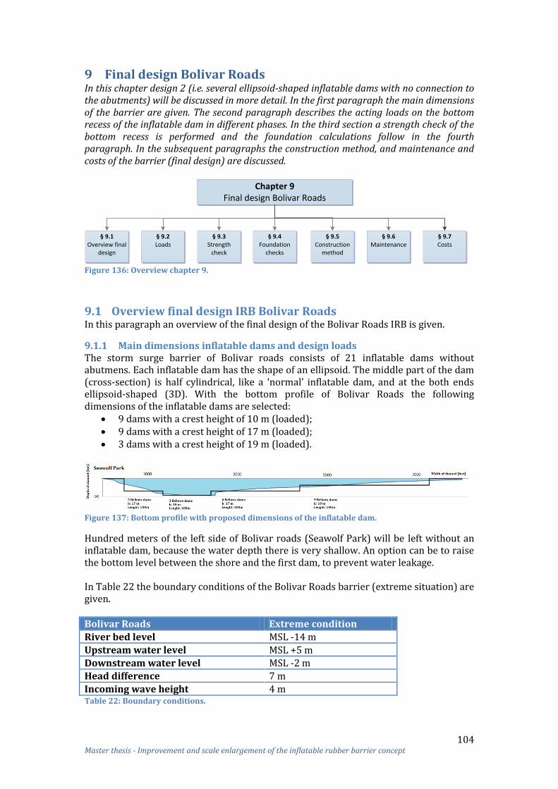
104 Master thesis - Improvement and scale enlargement of the inflatable rubber barrier concept
9 Final design Bolivar Roads In this chapter design 2 (i.e. several ellipsoid-shaped inflatable dams with no connection to the abutments) will be discussed in more detail. In the first paragraph the main dimensions of the barrier are given. The second paragraph describes the acting loads on the bottom recess of the inflatable dam in different phases. In the third section a strength check of the bottom recess is performed and the foundation calculations follow in the fourth paragraph. In the subsequent paragraphs the construction method, and maintenance and costs of the barrier (final design) are discussed.
Chapter 9Final design Bolivar Roads
§ 9.1Overview final
design
§ 9.2Loads
§ 9.3Strength
check
§ 9.4Foundation
checks
§ 9.5Construction
method
§ 9.6Maintenance
§ 9.7Costs
Figure 136: Overview chapter 9.
9.1 Overview final design IRB Bolivar Roads In this paragraph an overview of the final design of the Bolivar Roads IRB is given.
9.1.1 Main dimensions inflatable dams and design loads The storm surge barrier of Bolivar roads consists of 21 inflatable dams without abutmens. Each inflatable dam has the shape of an ellipsoid. The middle part of the dam (cross-section) is half cylindrical, like a ‘normal’ inflatable dam, and at the both ends ellipsoid-shaped (3D). With the bottom profile of Bolivar Roads the following dimensions of the inflatable dams are selected:
9 dams with a crest height of 10 m (loaded); 9 dams with a crest height of 17 m (loaded); 3 dams with a crest height of 19 m (loaded).
Figure 137: Bottom profile with proposed dimensions of the inflatable dam.
Hundred meters of the left side of Bolivar roads (Seawolf Park) will be left without an inflatable dam, because the water depth there is very shallow. An option can be to raise the bottom level between the shore and the first dam, to prevent water leakage. In Table 22 the boundary conditions of the Bolivar Roads barrier (extreme situation) are given.
Bolivar Roads Extreme condition
River bed level MSL -14 m
Upstream water level MSL +5 m
Downstream water level MSL -2 m Head difference 7 m
Incoming wave height 4 m Table 22: Boundary conditions.
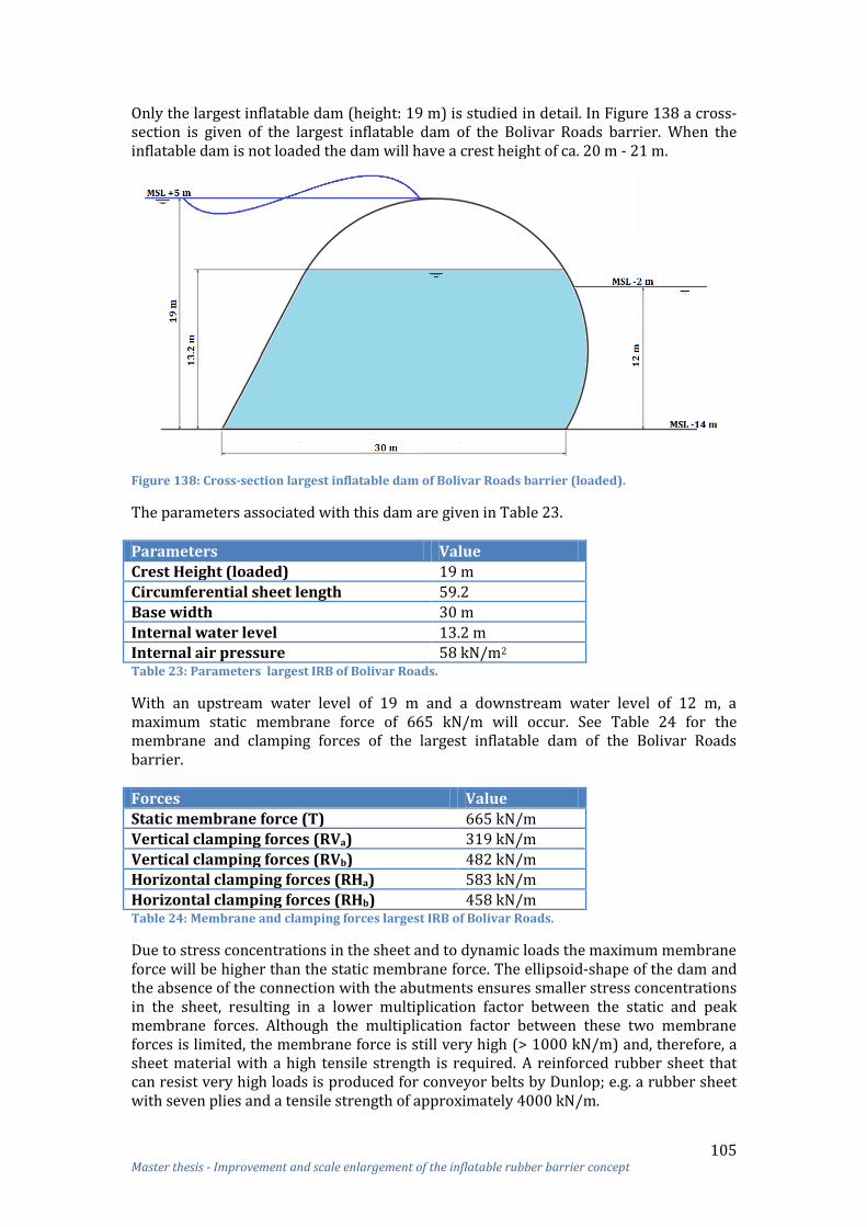
105 Master thesis - Improvement and scale enlargement of the inflatable rubber barrier concept
Only the largest inflatable dam (height: 19 m) is studied in detail. In Figure 138 a cross-section is given of the largest inflatable dam of the Bolivar Roads barrier. When the inflatable dam is not loaded the dam will have a crest height of ca. 20 m - 21 m.
Figure 138: Cross-section largest inflatable dam of Bolivar Roads barrier (loaded).
The parameters associated with this dam are given in Table 23. Parameters Value
Crest Height (loaded) 19 m
Circumferential sheet length 59.2
Base width 30 m
Internal water level 13.2 m Internal air pressure 58 kN/m2 Table 23: Parameters largest IRB of Bolivar Roads.
With an upstream water level of 19 m and a downstream water level of 12 m, a maximum static membrane force of 665 kN/m will occur. See Table 24 for the membrane and clamping forces of the largest inflatable dam of the Bolivar Roads barrier.
Forces Value
Static membrane force (T) 665 kN/m
Vertical clamping forces (RVa) 319 kN/m
Vertical clamping forces (RVb) 482 kN/m Horizontal clamping forces (RHa) 583 kN/m
Horizontal clamping forces (RHb) 458 kN/m Table 24: Membrane and clamping forces largest IRB of Bolivar Roads.
Due to stress concentrations in the sheet and to dynamic loads the maximum membrane force will be higher than the static membrane force. The ellipsoid-shape of the dam and the absence of the connection with the abutments ensures smaller stress concentrations in the sheet, resulting in a lower multiplication factor between the static and peak membrane forces. Although the multiplication factor between these two membrane forces is limited, the membrane force is still very high (> 1000 kN/m) and, therefore, a sheet material with a high tensile strength is required. A reinforced rubber sheet that can resist very high loads is produced for conveyor belts by Dunlop; e.g. a rubber sheet with seven plies and a tensile strength of approximately 4000 kN/m.

106 Master thesis - Improvement and scale enlargement of the inflatable rubber barrier concept
The total carcass thickness of the 7 plies of the Superfort® conveyor belt is 16 mm, see Figure 139. The cover thickness of the Superfort® conveyor belt is 4 mm for the top and 2 mm for the bottom. For the barrier a top thickness of 3 mm (as used for Ramspol) might also be sufficient.
Figure 139: Dunlop Conveyor belting Superfort® 7 plies
Due to the absence of the abutments, water leakage between the dams will occur, see Figure 140. The total percentage of water leakage with the chosen design will be around 5% (waves excluded). Waves will overtop the barrier which will cause more water leakage. When the biggest dam fails, 12% of the inlet will be open.
Figure 140: Water leakage.
9.1.2 Main dimensions bottom recesses There are three different sizes of bottom recesses; 9 small recesses, 9 middle size botom recesses and 3 large recesses. The length of each bottom recess is 100 m.
Figure 141: Bottom recess with position of the dimensions.

107 Master thesis - Improvement and scale enlargement of the inflatable rubber barrier concept
Nine inflatable dams with a crest height of 10 m requires the following dimensions: Base width in middle section: 16 m; Width bottom recess: 25 m; Inside depth bottom recess: 2.5 m.
Nine inflatable dams with a crest height of 17 m requires the following dimensions:
Base width in middle section: 27 m; Width bottom recess: 40 m; Inside depth bottom recess: 5 m.
Three inflatable dams with a crest height of 19 m requires the following dimensions:
Base width in middle section: 30 m; Width bottom recess: 45 m; Inside depth bottom recess: 5 m.
All bottom recesses are placed separately with some space between each other, to allow bottom settlement under each individual recess. The thickness of the elements of the bottom recess depends on the transfer of the loads to the environment. The element thickness of the bottom recess is calculated in paragraph 9.3.
9.2 Loads acting on bottom recess It should be checked whether or not all loads (in all load situations) actually can be resisted by the bottom recess. In this paragraph the acting loads in the distinguished stages of its lifetime are considered. It concerns the following lifetime stages:
Floating (transportation of the bottom recess); Immersion (sink down of the bottom recess); Immersed (final situation):
o Retaining (closed barrier); o Maintenance (inflatable dam filled with only air); o Stand by (barrier in rest).
Floating The barrier of Ramspol has been built by blocking off large sections of the river with a temporary cofferdam, which allows dewatering the area surrounded by the sheet piles and then proceeding with foundations followed by the superstructure. An alternative to the approach is a method referred to as ‘float-in’ construction that involves constructing the bottom recess on shore and transported floating to the final position. These concepts offered several advantages over conventional ‘In-the-Dry’ construction: 26
Less disruption to river navigation and river flow; Lower cost of construction due to the elimination of conventional large sheet
pile cofferdams and site dewatering; Less environmental impact by reducing dredging activities and elimination of
site dewatering; Higher quality by allowing the use of concrete, produced in a controlled onshore
environment. More information about the construction method is treated in paragraph 9.6.
26 Bittner, R. and Miles, W., Lock Review (Braddock) - PIANC - WG29

108 Master thesis - Improvement and scale enlargement of the inflatable rubber barrier concept
During floating of the bottom recess, considerable hydrostatic forces are acting on the outside of the bottom recess, which is not balanced by a counter load of ballast on the inside (Figure 142).
Figure 142: Loads acting on the bottom recess during floating.
Immersion After the transportation of the bottom recess to its final position it will be immersed and placed on excavated soil. During the start of the sink down phase the situation is slightly different from floating; the bottom recess is still floating, but some ballast water has been let in. Immersed When the bottom recess is immersed three situations can occur:
Retaining (closed barrier); Maintenance (inflatable dam filled with only air); Stand by (barrier in rest).
Retaining During retaining, the normative situation is the situation where the upstream water level is MSL +5 m and the downstream water level MSL -2 m. The membrane forces are distributed via the clamping structures to the bottom recess. For the calculation of the membrane force the upstream and downstream hydrostatic water pressure, the internal air pressure and the internal hydrostatic water pressure are included. The membrane forces are divided in a horizontal and vertical clamping force, see Figure 143. Due to the large difference between the upstream and downstream water level, large horizontal clamping forces will be acting on the bottom recess.
Figure 143: Tension force divided in a horizontal and vertical clamping force.

109 Master thesis - Improvement and scale enlargement of the inflatable rubber barrier concept
The application point of the clamping forces (red arrows in Figure 144) is on top of the bottom recess. Other loads will be acting on the bottom recess as well. Outside the bottom recess a water pressure (dark blue), a soil pressure (orange) and an upstream groundwater pressure (green) will be acting on the walls and floor of the bottom recess. At the inside a water pressure (light blue) will be acting on the walls, top slab and floor of the bottom recess.
Figure 144: Loads acting on the bottom recess (stationary situation).
The upward directed water pressure beneath the bottom recess dependents on the water level on both sides of the inflatable dam. In Figure 144 the upstream pressure is showed for the stationary situation. It may take some time before this stationary situation is reached. Till that time, a smaller upward directed water pressure will be present. The stationary situation will be applied for the calculations to create more safety margin. When the upward directed water pressure is too large an option is to place sheet pile walls beneath the bottom recess to reduce the upward water pressure. Maintenance During maintenance activities inside the inflatable dam, it is necessary to fill the dam with air only. This situation differs from the normal retaining situation; large vertical clamping forces will act on the bottom recess. These tension forces cause large shear forces and bending moments in the bottom recess and also undesired floating of the bottom recess. To prevent this, a counteracting force should be present. An option is to place a kind of ballasted cofferdam on top of the top slabs of the recess to counteract the tension forces in the foundation, see Figure 145.
Figure 145: Ballasted cofferdam on top of the top slabs for maintenance.

110 Master thesis - Improvement and scale enlargement of the inflatable rubber barrier concept
To decrease the shear forces and bending moments in the bottom recess the weight of the cofferdam should be the same or larger compared to the vertical clamping forces. The weight of the cofferdam can be increased with ballast (water, sand, et cetera). This cofferdam should also be helpful for maintenance purposes from the outside. Stand by When the inflatable dam is standby (in rest), the sheet is stored in the bottom recess and no clamping forces are acting on the bottom recess.
9.3 Strength check of largest bottom recess The required strength of the bottom recess depends on the shape and dimensions of the structure and the strength properties of the construction materials. The dimensions of the bottom recess are chosen with respect to other requirements than strength or stiffness alone. The bottom recess has two functions:
Storage of sheet; Transfer of the loads to the environment.
Both aspects have an influence on the dimensions of the bottom recess. Due to the storage of the sheet, the depth and width of the bottom recess are already determined. The thickness of the elements of the bottom recess is dependent on the transfer of the loads to the environment. It should be checked if all the loads acting on the bottom recess (in all load situations) can be resisted by the bottom recess. Therefore, the maximum shear force and maximum bending moment in the bottom recess are checked. The normative load situation for the stresses and moments in the concrete elements of the bottom recess will occur during the retaining or maintenance phase due to the large clamping forces. Therefore, a strength check is only performed for these two phases. For a first strength calculation, a cross-section in the middle of the largest bottom recess is considered. The first step is to schematise the structure and the acting loads. Then the maximum shear forces and maximum bending moments should be checked. A 2D hand calculation provides a fairly accurate indication of the dimensions of the bottom recess. However, a more precise calculation should follow taking into account, e.g. the spread of forces in multiple directions, which is beyond the scope of this research. Therefore, it is recommended to perform 3D FEM calculations in a later stadia. The final dimensions of the bottom recess depends on the shear forces and bending moments. In Appendix 18 the complete strength check can be found.
9.3.1 Shear force The thickness of the walls and floor is first determined without shear reinforcement. In the Eurocode 2 a formula for the shear capacity VRd, c is given. VRd, c is the design value of the shear resistance of the element without shear reinforcement.
[
]
With a minimum of ( )
Where

111 Master thesis - Improvement and scale enlargement of the inflatable rubber barrier concept
Initially, reinforcement of is applied. In Table 25 the design value for the shear resistance for several heights is given.
h: 1000 mm
h: 1500 mm
h: 2000 mm
h: 2500 mm
h: 3000 mm
482 602 710 804 900
314 440 561 678 795 Table 25: Shear resistance of the element without shear reinforcement.
In Table 26 the thickness of the elements of the bottom recess are given.
Part Normative situation
Max shear force Thickness without shear reinforcement
Top slabs Maintenance 700 kN/m 2 m
Wall left Retaining 790 kN/m 2.5 m
Wall right Retaining 870 kN/m 3 m
Bottom slab Retaining 450 kN/m 1 m Table 26: Elements thickness bottom recess based on the shear force without shear reinforcement.
With shear reinforcement the thickness of the elements can be reduced. For the bottom slab no shear reinforcement is needed, but for the top slabs and walls shear reinforcement can be an option. With the following formula the shear resistance of the element with shear reinforcement can be calculated:
In Table 27 the design values for the shear resistance for several heights are given.
h: 500 mm
h: 700 mm
h: 1000 mm
h: 1000 mm
h: 1500 mm
St, max 318 mm 468 mm 600 mm 600 mm 600 mm
Reinforcement
VRd, c 667.3 kN/m 736.8 kN/m 727 kN/m 920 kN/m 1121 kN/m Table 27: Shear resistance of the element with shear reinforcement.
Using shear reinforcement, a 1 m thick bottom slab, 1 m thick walls and 1 m thick top slabs can be applied, see Table 28.
Part Normative situation
Max shear force
Shear reinforcement
Thickness with shear reinforcement
Top slabs Maintenance 700 kN/m 1 m
Wall left Retaining 790 kN/m
1 m 1.5 m
Wall right Retaining 870 kN/m
1 m 1.5
Bottom slab Retaining 450 kN/m - - Table 28: Element thickness with shear reinforcement.

112 Master thesis - Improvement and scale enlargement of the inflatable rubber barrier concept
9.3.2 Bending moment A reinforcement percentage of 1.25 % and concrete quality C45/55 is chosen for this
calculation. For this percentage and concrete quality a value of 150 for
is given.
Now the thickness of the elements can be calculated with the following formula:
√
In Table 29 the thickness of the elements of the bottom recess are given.
Part Normative situation
Max Bending moment
Thickness
Top slab left Maintenance 3600 kNm/m 1 m
Top slab right Retaining 3850 kNm/m 1 m
Wall left Maintenance 3600 kNm/m 1 m
Wall right Retaining 8400 kNm/m 1.5 m
Bottom slab Retaining 7800 kNm/m 1.5 m Table 29: Thickness of elements bottom recess based on the bending moments.
9.3.3 Combination shear force and bending moment See Table 30 for the thickness of the top slabs, walls and bottom slab of the bottom recess.
Due to shear force Due to bending moment
Due to shear force and bending moment
Thickness without shear reinforcement
Thickness with shear reinforcement
Thickness with 1.25 % reinforcement
Thickness with 1.25 % reinf. and shear reinf.
Top slab left 2 m 1 m 1 m 1 m
Top slab right 2 m 1 m 1 m 1 m Wall left 2.5 m 1 m - 1.5 m 1 m 1.5 m (symmetry)
Wall right 3 m 1 m - 1.5 m 1.5 m 1.5 m
Bottom slab 1 m - 1.5 m 1.5 m (no shear reinf) Table 30: Thickness of elements bottom recess based on the shear forces and bending moments.
Without shear reinforcement a large thickness of the top slabs and walls is required. Therefore, shear reinforcement should be applied. With shear reinforcement the thickness can be reduced to 1 m, but a minimal thickness of 1.5 m is required for the walls due to the bending moment. With a higher percentage of reinforcement than 1.25% it might be possible to reduce the thickness of the walls to 1 m, but more reinforcement is economical not feasible. A bottom slab of 1.5 m is required due to the bending moment.
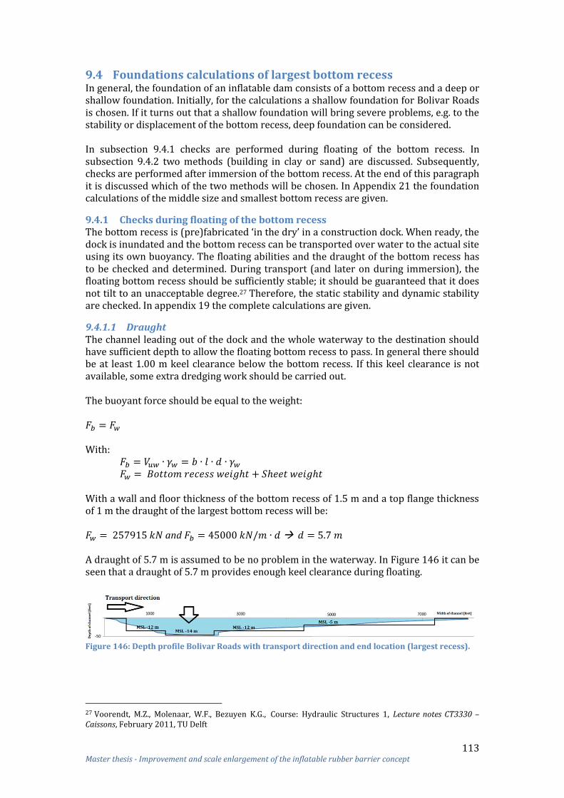
113 Master thesis - Improvement and scale enlargement of the inflatable rubber barrier concept
9.4 Foundations calculations of largest bottom recess In general, the foundation of an inflatable dam consists of a bottom recess and a deep or shallow foundation. Initially, for the calculations a shallow foundation for Bolivar Roads is chosen. If it turns out that a shallow foundation will bring severe problems, e.g. to the stability or displacement of the bottom recess, deep foundation can be considered. In subsection 9.4.1 checks are performed during floating of the bottom recess. In subsection 9.4.2 two methods (building in clay or sand) are discussed. Subsequently, checks are performed after immersion of the bottom recess. At the end of this paragraph it is discussed which of the two methods will be chosen. In Appendix 21 the foundation calculations of the middle size and smallest bottom recess are given.
9.4.1 Checks during floating of the bottom recess The bottom recess is (pre)fabricated ‘in the dry’ in a construction dock. When ready, the dock is inundated and the bottom recess can be transported over water to the actual site using its own buoyancy. The floating abilities and the draught of the bottom recess has to be checked and determined. During transport (and later on during immersion), the floating bottom recess should be sufficiently stable; it should be guaranteed that it does not tilt to an unacceptable degree.27 Therefore, the static stability and dynamic stability are checked. In appendix 19 the complete calculations are given.
9.4.1.1 Draught The channel leading out of the dock and the whole waterway to the destination should have sufficient depth to allow the floating bottom recess to pass. In general there should be at least 1.00 m keel clearance below the bottom recess. If this keel clearance is not available, some extra dredging work should be carried out. The buoyant force should be equal to the weight: With: With a wall and floor thickness of the bottom recess of 1.5 m and a top flange thickness of 1 m the draught of the largest bottom recess will be: and A draught of 5.7 m is assumed to be no problem in the waterway. In Figure 146 it can be seen that a draught of 5.7 m provides enough keel clearance during floating.
Figure 146: Depth profile Bolivar Roads with transport direction and end location (largest recess).
27 Voorendt, M.Z., Molenaar, W.F., Bezuyen K.G., Course: Hydraulic Structures 1, Lecture notes CT3330 – Caissons, February 2011, TU Delft

114 Master thesis - Improvement and scale enlargement of the inflatable rubber barrier concept
9.4.1.2 Static stability The stability of a floating object is its ability to counteract forces eventually overturning the bottom recess. Tilting of the bottom recess during transport or immersion could cause inconvenience or damage and should be restricted. The design should therefore provide a righting moment if tilt is initiated in such a way that the bottom recess will turn back to its neutral position. To avoid instability of the bottom recess (too big rotation around the length axis), its metacentric height – the distance between the centre of gravity and the metacentre – should be more than 0.5 meters.28 The metacentric height:
∑
∑
∑
∑
Figure 147: Floating element (Hydraulic Structures Caissons).
Because the width (b) of the bottom recess is relatively large and the height relatively small, the chance of overturning is very small; the metacentre is much higher than 0.5 m. After the transportation of the bottom recess, it can be immersed. A calculation is made with 10 cm of water inside the bottom recess. The largest bottom recess with 10 cm of water has a weight of: and a draught of:
28 Voorendt, M.Z., Molenaar, W.F., Bezuyen K.G., Course: Hydraulic Structures 1, Lecture notes CT3330 – Caissons, February 2011, TU Delft

115 Master thesis - Improvement and scale enlargement of the inflatable rubber barrier concept
The metacentric height:
∑
∑
For this situation the metacentric height is also much more than the required 0.5 meter. Therefore, the risk of overturning is negligible.
9.4.1.3 Dynamic stability Not only the static stability but also the dynamic stability should be checked. If an element is transported over water, it will be affected by waves or swell. This can cause the element to sway, which can cause problems with respect to navigability and clearance. Therefore, considerable swinging of the bottom recess on the waves or swell should be avoided. If the dimensions (length or width) of a floating element are too small compared to the length of the waves or swell, the element will start swaying on the waves. In practice, the following rule of thumb is being used. When the wave direction is parallel to the length axis of the bottom recess: = 70 m When the wave direction is perpendicular to the length axis of the bottom recess: = 31.5 m where the wave or swell length is. The bottom recess should be transported over water when the weather conditions are calm. The dimensions of the bottom recess are sufficient compared to the length of the waves or swell. Therefore, it is concluded that no problems will occur with swaying on the waves or swell.
9.4.2 Building in sand or clay In the retaining phase, the bottom recess will be pushed to the side due to the large water level difference. Due to this forced movement, the horizontal soil pressure can be calculated with an active and passive coefficient. The horizontal soil pressure consist of a water pressure and a vertical effective stress multiplied with an earth pressure coefficient. This coefficient dependents on the angle of internal friction of the subsoil ( ). A distinction can be made between the active, the passive and the at rest earth pressure coefficient. The active state ( ) occurs when a soil mass is allowed to relax or move outward to the point of reaching the limiting strength of the soil. The passive state ( ) occurs when a soil mass is externally forced to the limiting strength.
The soil of Bolivar Roads consists of a sand layer (MSL -3 m to MSL -15 m), several clay layers (MSL -15 m to MSL -40 m) and a deep sand layer (MSL -40 m to 50 m). The largest bottom recess is located in the clay layer and therefore the calculations should be made with the earth pressure coefficients of clay.

116 Master thesis - Improvement and scale enlargement of the inflatable rubber barrier concept
With the angle of internal friction of clay of , this leads to the following earth pressure coefficients:
(
)
(
)
An option can be to excavate a large surface around the bottom recess (and sheet pile walls) and replace it by sand, allowing to use the earth pressure coefficients of sand for the calculations. It is important that enough soil around the bottom recess (and sheet pile walls) is excavated and replaced with sand if the calculations are based on earth pressure coefficients of sand. This is because the failure plane might be larger than the area around the bottom recess, when the friction between clay and sand is small. To prevent this failure mechanism, enough soil must be excavated. For now on it is assumed that when 2 meters beneath the bottom recess/ sheet pile walls and the active and passive zone is excavated, this failure mechanism will not occur. For future analyses it must be checked if the assumed 2 meters is enough to prevent this failure mechanism. See Figure 148 for the passive and active zone and the excavation area. The red line in the figure indicates the border of the surface that needs to be excavated and replaced by sand to allow the calculation with the earth pressure coefficients of sand possible.
Figure 148: Passive and active zone; Left: without sheet pile walls; Right: with sheet pile walls.
When the bottom recess is built in a sand layer, the angle of internal friction of the subsoil is . This leads to the following earth pressure coefficients:
(
)
(
)
In the following subsections it is calculated if both methods (building in clay or in sand) can be applied. When both methods can be applied a calculation can be made to determine which method is the least expensive. This is presented in subsection 9.4.4.
9.4.3 Checks after immersion of the bottom recess For the immersed phase the following checks should be performed: undesired floating, shear criterion, rotational stability, vertical bearing capacity, settlement, sliding circle and piping. In Table 31 is showed which checks should be performed for which situation. Retaining Maintenance Stand by
Undesired floating Yes Yes Yes
Shear criterion Yes No No
Rotational stability Yes No No
Vertical bearing capacity Yes Yes No Settlement Yes Yes Yes
Sliding circle Yes No No
Piping Yes No No Table 31: Summarized which checks for which phase.

117 Master thesis - Improvement and scale enlargement of the inflatable rubber barrier concept
In the following subsections these checks are briefly discussed. In appendix 20 these checks are discussed in more detail.
9.4.3.1 Dimensions to prevent undesired floating With the calculated dimension based on the strength (check), the inflatable dam will float up after placement. To prevent floating the weight of the bottom recess should be increased. With a bottom slab thickness of 2.5 m instead of 1.5 m undesired floating can be prevented. It can be concluded that sheet pile walls and a bottom slab of 2.5 m thick are required to prevent undesired floating. For the maintenance phase a ballasted cofferdam is required. In Figure 149 a cross-section of the largest bottom recess with the final dimensions is shown.
Figure 149: Cross-section bottom recess with dimensions to prevent floating.
With this new dimensions the draught must be checked again. The buoyant force should be equal to the weight: The weight of the bottom recess: With a floor thickness of the bottom recess of 2.5 m the draught of the largest bottom recess will be: and The draught is larger than the height of the bottom recess. The draught can be reduced by adding additional buoyancy during transport, for instance floating bodies. Another option is to apply compartments in the bottom slab of the recess in order to reduce the weight, see Figure 150. After transportation these compartments can be filled first with water to allow the bottom recess to sink and then infilling of the compartments with e.g. tremie concrete.
Figure 150: Bottom recess with holes in the bottom slab to reduce weight.
An alternative option is to lift the bottom recess with a special vessel instead of floating. Unfortunately this is much more expensive. Therefore, floating of the bottom recess to its final position is recommended.

118 Master thesis - Improvement and scale enlargement of the inflatable rubber barrier concept
9.4.3.2 Shearing To prevent shearing the sum of the horizontal forces should be smaller than the friction between the surrounding structure and subsoil. This can be checked by this formula: ∑
∑
To prevent shearing, skirts of 8 m deep are needed in the clay layer. Skirts of 2.5 m are needed to prevent shearing in the sand layer. Clay layer with bottom slab 2.5 m thick + skirted wall 8 m:
∑
∑
Sand layer bottom slab 2.5 m thick + skirted wall 2.5 m:
∑
∑
9.4.3.3 Rotational stability Because of the eccentric loading on the floor the subsoil may undergo some shearing. This might cause tilt over of the structure. With the following formula stability of the structure can be checked: ∑
∑
Clay layer with bottom slab 2.5 m thick + skirted wall 8 m:
∑
∑
Sand layer with bottom slab 2.5 m thick + skirted wall 2.5 m:
∑
∑
Overturning will not be a problem for both methods.
9.4.3.4 Vertical bearing capacity The required vertical effective soil stress should not exceed the maximum bearing capacity of the soil, otherwise the soil will collapse. The maximum acting stress on the soil can be calculated with:
∑
∑
Where is the maximum stress of the subsoil. If this is exceeded, the subsoil should be adjusted or a foundation with piles should be considered. The TGB 1990 (NEN 6744) gives the Brinch Hansen method for determining the maximum bearing force of a foundation. This method is based on Prandtl’s theoretical sliding surfaces.

119 Master thesis - Improvement and scale enlargement of the inflatable rubber barrier concept
Figure 151: Prandtl and Brinch Hansen.
Clay layer with bottom slab 2.5 m thick + skirted wall 8 m: A smaller bearing capacity will be present in undrained conditions. The calculation of undrained situation will be normative compared to the drained situation and therefore only the calculation of undrained situation will be given. For saturated clay soils the initial loading present undrained conditions in which and , and
, so the equation becomes:
∑
∑
∑
∑
Sand layer with bottom slab 2.5 m thick + skirted wall 2.5 m: , so the equation becomes:
∑
∑
∑
∑
9.4.3.5 Settlement The load in the new situation is less than the original load; settlement will not occur. Initial vertical effective stress:
New vertical effective stress:
When there is an increased piezometric level in one of the layers the construction risk of bursting up will be present because the dead weight of the structure is less than the original soil pressure. Also heave of the soil layer might be a problem when the weight of the structure is smaller than the original weight of the soil. When the soil layers are relatively permeable, heave will take place during dredging, which won’t cause any problems. A more extensive soil investigation must be carried out to draw conclusions about the risk of bursting up and heave.

120 Master thesis - Improvement and scale enlargement of the inflatable rubber barrier concept
9.4.3.6 Slip circle With Bishop’s iterative formula is the stability of slopes based on circular slide surfaces checked :
∑
∑
The stability check consists of dividing the soil into slices of equal width, measuring α and h for each slice and then determining the safety factor F. The verification should be carried out for several sliding surfaces (different centre points and radii). The smallest value of F (corresponding to the most critical sliding surface) has to be greater than F = 1.3 for permanent works.29 The calculation is carried out by the computer programme D-GEO Stabality of Deltares. The smallest value of F (corresponding to the most critical sliding surface) is 5.280 which is much greater than F = 1.3 for permanent works. Therefore, it is concluded that no problems will occur with stability.
9.4.3.7 Piping Piping is the flow of water through a pipe-like channel that has been created by internal erosion. This phenomenon can occur along the foundation plane of the bottom recess. Sheet piling might be necessary to prevent this piping. When the bottom recess is placed in the clay layer (impermeable soil) piping would not occur. For the other method, when the soil is excavated and replaced by sand, piping under the bottom recess might occur. The formula of Lane is used to describe the critical situations in which piping can occur.
∑ ∑
. For building in sand, skirt walls of 2.5 m are already present, but this length is too short to prevent piping. Walls with a minimum length of 5.625 m placed on both sides under the bottom recess are needed to prevent piping.
9.4.4 Choice of method based on costs (building in clay or sand) For the calculation based on clay, a skirted wall of 8 m long is needed. For the calculation based on sand a much smaller skirt length is required: 2.5 m. However, sheet pile walls of minimal 5.625 m (rounded to 6 m) are needed to prevent piping in the sand layer. Therefore, the actual difference in length of the skirted walls is only 2 m. Because both methods can be applied, the choice of which method is preferred can be based on the cost. Method 1 with clay: Extra skirt length: Costs extra skirts:
29 Course: Hydraulic Structures 1, Lecture notes CT3330 – General, November 2009, TU Delft

121 Master thesis - Improvement and scale enlargement of the inflatable rubber barrier concept
Method 2 with sand:
(
(
)
)
(
)
Costs extra excavation area: With this simplified cost calculation method 1 seems to be the least expensive. It is advised to carry out a more extensive cost calculation in order to determine which method should be applied. For now on method 1 is chosen as the favourable method for the Bolivar Roads barrier.
9.5 Construction method In this paragraph the construction method of the Bolivar Roads barrier will be discussed. It is recommended to perform more research about the optimal construction method. The construction method consists of the following topics:
Excavation of the soil, placement of the foundation bed, and construction of the control buildings;
Construction of the dock; Construction of the bottom recess; Production of the rubber sheets; Connection of the sheets to the bottom recess; Testing of the inflatable dam; Transportation of the bottom recess with sheet; Installation of the bottom recess.
These subjects are explained in further detail in the following subsections.
9.5.1 Excavation, foundation bed and construction of control buildings Before the placement of the bottom recesses, the soil must be excavated to several depths (footprint of the inflatable dam foundation); i.e from left (Seawolf Park) to right (Fort Travis Seashore Park):
300 m length at MSL -18.5 m (3 x bottom recess 100 m, with a height of 6.5 m); 300 m length at MSL -21.5 m (3 x bottom recess 100 m, with a height of 7.5 m); 600 m length at MSL -18.5 m (6 x bottom recess 100 m, with a height of 6.5 m); 900 m length at MSL -8.5 m (9 x bottom recess 100 m, with a height of 3.5 m).
The soil level steps of 3 m and 10 m (see Figure 152) can be maintained by placing temporary sheet pile walls.
Figure 152: Bottom profile after excavation.
Dredging could be performed in two stages. The first stage of pre-excavation involves a wide strip under the footprint of the inflatable dam foundation. The depth of the excavation varies from MSL -8.5 to MSL -21.5 m. Temporary sheet pile walls must be installed in order to retain the soil. The excavation should be inclined up to the existing river bed grade at a slope of 1 on 10 upstream and 1 on 5 downstream. The dredging materials can be transported by barge to the disposal site. The sea bed of Bolivar Roads can be compacted over a large width to improve the bearing capacity of the sea bed even further and to prevent settlements caused by shear movements. The foundation bed must be completed after the placement of the pipelines and skirts.
122 Master thesis - Improvement and scale enlargement of the inflatable rubber barrier concept
Each inflatable dam will need its own equipment, like large water inlets, blowers, emptying pumps, a vacuum system, various butterfly valves, pipelines, inflatable dam measuring systems, et cetera. For the Bolivar Roads barrier two control buildings should be built at each shore. In these buildings the equipment (and all moving elements) for each dam should be accommodated. The equipment must be placed above sea level to prevent failure of the equipment by flooding of the control building. The pipe lines that should be installed between the control buildings and the dam can be placed in the foundation bed, next to the barrier or in the bottom recesses. Underneath the base slab of the bottom recess a system of steel skirted walls should be penetrated 4.5 m (smallest bottom recess) to 8 m deep into the soil in order to prevent sliding along the sea bed surface from being the prevailing failure mechanism. This method does not need excavation of the soil, and hence it cannot be restricted by the presence of a high water table. Construction of vertical skirts at the base of the foundation confines the underlying soil and generates soil resistance on the skirt side, helping the footing to resist sliding. The skirted foundations can be made of steel or concrete. Yet, a skirt length of 8 m is needed, steel is preferred as material. Therefore, sheet pile walls are used as skirt foundation. An option is to penetrate the skirts into the soil by the weight of the structure, but this process might have a larger failure chance compared to the situation wherein the sheet pill walls are drilled into the soil. Therefore, the sheet pill walls should be drilled in the soil from a pontoon. At the position of the Bolivar Roads barrier and its near surroundings, a large area of the bed must be protected, which must prevent erosion under the barrier when the dam is inflated and should protect the bottom near the dams when large water velocities occur. The bed protection must also prevent sliding of the bottom recess by keeping enough distance between the scour hole on both sides of the barrier. The scour depth in front of the barrier may, under the worst conditions, reach values up to 0.7 times the original water depth. Scour can be prevented by applying geometrically tight granular or geotextile filters. On both sides of the barrier concrete block mattresses, with a large length (assumed 300 m) should be applied. The concrete blocks are attached to a layer of geotextile with plastic pins in order to make the mattresses sink and to ensure the stability of the mattresses at the bottom. The foundation mattresses are prefabricated and a special equipment vessel is used to transport the mattresses from the plant to their final destination to bring them in position. After sinking, the mattresses should be covered with steel slags for more stability in the turbulent currents. Besides the concrete block mattresses and the filter mattresses, also large rocks and concrete blocks should be placed in order to protect the foundation of the dam barrier. The foundation bed must be complete in such a way that a bottom recess can be immersed over the foundation. With the skirted walls in place, the area between the walls can be excavated. Under the barrier a filter mattress, a combination of a geometrically closed granular filter and geotextiles, should be placed. Failure caused by an unlevelled bed can be prevented by ensuring that the bed is reasonably smooth.
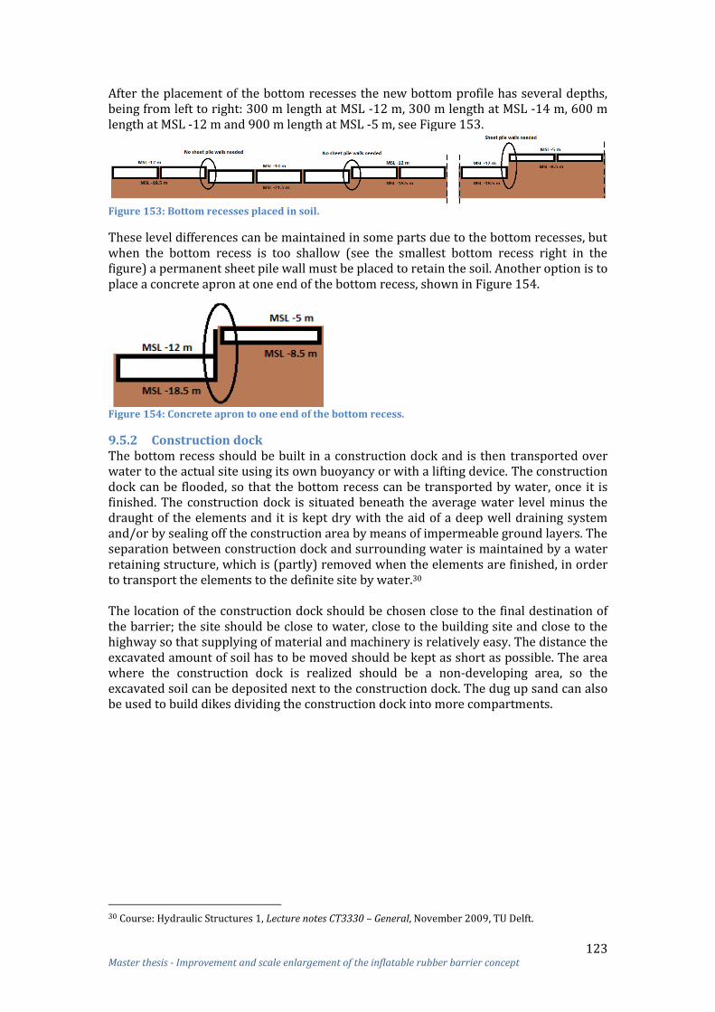
123 Master thesis - Improvement and scale enlargement of the inflatable rubber barrier concept
After the placement of the bottom recesses the new bottom profile has several depths, being from left to right: 300 m length at MSL -12 m, 300 m length at MSL -14 m, 600 m length at MSL -12 m and 900 m length at MSL -5 m, see Figure 153.
Figure 153: Bottom recesses placed in soil.
These level differences can be maintained in some parts due to the bottom recesses, but when the bottom recess is too shallow (see the smallest bottom recess right in the figure) a permanent sheet pile wall must be placed to retain the soil. Another option is to place a concrete apron at one end of the bottom recess, shown in Figure 154.
Figure 154: Concrete apron to one end of the bottom recess.
9.5.2 Construction dock The bottom recess should be built in a construction dock and is then transported over water to the actual site using its own buoyancy or with a lifting device. The construction dock can be flooded, so that the bottom recess can be transported by water, once it is finished. The construction dock is situated beneath the average water level minus the draught of the elements and it is kept dry with the aid of a deep well draining system and/or by sealing off the construction area by means of impermeable ground layers. The separation between construction dock and surrounding water is maintained by a water retaining structure, which is (partly) removed when the elements are finished, in order to transport the elements to the definite site by water.30 The location of the construction dock should be chosen close to the final destination of the barrier; the site should be close to water, close to the building site and close to the highway so that supplying of material and machinery is relatively easy. The distance the excavated amount of soil has to be moved should be kept as short as possible. The area where the construction dock is realized should be a non-developing area, so the excavated soil can be deposited next to the construction dock. The dug up sand can also be used to build dikes dividing the construction dock into more compartments.
30 Course: Hydraulic Structures 1, Lecture notes CT3330 – General, November 2009, TU Delft.

124 Master thesis - Improvement and scale enlargement of the inflatable rubber barrier concept
Figure 155: Options for the location of the construction dock.
The slopes of the construction dock should be as steep as the stability permits in order to limit the amount of earthmoving that is needed, because less steep slopes result in more excavation work. The slope stability depends on the type of soil, the groundwater level, the depth of the excavation and whether or not banquettes are present. The construction docks are provided with all building facilities. There will be a concrete batching plant in the dock area next to a reinforcement bar yard, and a storage and assembling place for formwork elements and an area for storing other materials. If not already available, temporary accommodations for the workers will be built.
9.5.3 Construction of bottom recess The concrete bottom recess will be casted in situ in the construction dock since the transport of the large prefabricated elements would be difficult and expensive. Casts in situ instead of prefabricated elements is in this case also chosen because a lot of repetition will be present due to the construction of a large number of bottom recesses causing that e.g. the formwork can be reused, which reduces the equipment cost. For the construction of the bottom recess a formwork is needed to cast the floors, walls and top slabs of the recesses. The time needed to assemble and disassemble the formwork is not critical. Therefore, traditional formworks can be chosen. Further analysis is needed to determine whether a traditional formwork is possible for the recess walls; otherwise a ‘climbing’ formwork (i.e. a special type of formwork for vertical concrete structures that rises with the building process) should be used.
Figure 156: Cross-section bottom recess Bolivar Roads barrier.
The concrete will be produced on the mainland and brought to the construction site with a concrete pump. Concrete can be blended in a local concrete batching plant with sufficient production capacity. First the bottom slab is casted, and when it has hardened, the walls and then the top slabs follow. During the hardening process of the concrete, other activities, such as placing the bed protection, can be executed.

125 Master thesis - Improvement and scale enlargement of the inflatable rubber barrier concept
The bottom slab of the bottom recesses will be produced in one shift. In the bottom slab hollow compartments and two recesses should be applied. The vertical walls of the largest and middle-size bottom recesses will be concreted in two shifts, because the maximum height limitation of a climbing formwork is 3.5 m. The vertical walls have a height of 4 m, so a formwork of 2 m can be used. The top slabs follow after the vertical walls have been concreted and hardened. After hardening of all concrete elements, low-friction UHMWPE should be applied in the bottom recess in order to improve the storage of the rubber sheet of the inflatable dam.
9.5.4 Production of rubber sheet of inflatable dam The sheets will be produced by a company specialized in processing rubber composite. A factory where the production of the sheets takes place should be built near the construction dock, to minimize transportation activities. Building a rubber factory near the construction dock can be economically feasible because of the smaller transportation cost and the high quantity of sheets (i.e. 21) which should be produced for this barrier. The factory can be mothballed for later use after finalisation of all sheets and be (re)started-up in future in case of sheet replacement. The sheets of the inflatable dams have an ellipsoid shape, causing that the sheet has not a completely flat form in disassembled condition. The ellipsoid shape can be made by cutting (pointed) ellipses at both ends of the rectangular rubber sheet. The middle part of the rubber sheet should be rectangular, because this part should be formed into a half cylinder configuration. To form the shape of the dam a wooden mold can be constructed, which has the shape of the inflated dam. Another option is to use a mold of sand. The rubber sheet should be laid over the mold and the longitudinal edges of the ellipses should be vulcanized to each other. This will be done at the way described in paragraph 3.3. For the production of the sheet it is important that the reinforcement is laid in such a way that when the dam is inflated the reinforcement will be in circumferential direction, see Figure 157.
Figure 157: Reinforcement in circumferential direction.
In order to clamp the sheet, some overlength of the sheet is needed, see Figure 158. Therefore, a strip of a few dozen centimetres should be present at the ellipsoid-shaped end which can be clamped into the structure.
Figure 158: Overlength for clamping.
9.5.5 Connection of rubber sheet with bottom recess After the concrete of the elements of the bottom recess has hardened, the clamping structure and the sheet can be connected to it. The sheets should be transported and exactly placed on the proper location in the clamping structure on the bottom recess using a crane.

126 Master thesis - Improvement and scale enlargement of the inflatable rubber barrier concept
The same clamping structure as used for the horizontal part of the inflatable dam of Ramspol can be used for the Bolivar Roads barrier; i.e. a so-called ‘teeth’ clamp. This clamp consist of a bottom plate and a top plate between which the sheet is clamped, see Figure 159. This unity is attached to the concrete foundation with pre-stressed bolts with a centre-to-centre distance of 150 mm.
Figure 159: Teeth clamp.
The clamping structure is positioned in an angle at the bottom recess to prevent extra stresses in the sheet while the dam is inflated, see Figure 160 and Figure 161. There are two options given how the clamping structure can be placed. In option 1, one clamping structure is situated inside the inflatable dam, while the other is situated outside the dam. In option 2 both clamping structures are situated inside the dam.
Figure 160: Clamping structure on bottom recess option 1.
Figure 161: Clamping structure on bottom recess option 2.
The overlength of the sheet at the ellipsoid-shaped end (black strip in Figure 158) should be clamped into the structure.

127 Master thesis - Improvement and scale enlargement of the inflatable rubber barrier concept
In Germany a similar clamping structure is used for inflatable dams, yet an extra piece of rubber is clamped between the top plate of the clamp and the rubber sheet, in order to protect the sheet, see Figure 162. It might be an appropriate option to also place an extra piece of sheet in the clamping structures of the Bolivar Roads barrier.
Figure 162: Extra piece of rubber in clamping structure.
9.5.6 Testing Before filling the construction dock with water, the inflatable dam should be tested. First, the pumps will be tested and the system will be inspected for leakage(s). For this purpose a temporary connection between the pumps and the inflatable dams must be made. Second, the construction dock will be inundated to test the floating abilities of the bottom recess. If the tests are positive, the dam is ready for use and can be transported to its final destination.
9.5.7 Transport When a bottom recess is ready for transportation, the basin should be flooded to the river elevation level. Then the exit sheet-pile wall can be removed and depending on the tide, the water in the flooded basin reaches a depth allowing a lifting or towing vessel to lift or tow the bottom recesses out of the casting facility and to transport them to their final destination. It is preferred that the bottom recesses are floated due to the lower costs. The bottom recesses should be transported from the construction dock to their final destination during high water level. When the bottom recesses are floated, transport can be performed using a primary tow boat and guided as necessary by a snubbing tow boat. Additional buoyancy can be added to decrease the draught. In general the low tidal turn is a better moment to immerse the bottom recesses because of the shorter immersion height (the shorter the immersion height, the less risk of failure), unless the course of the flow conditions appears to be much better during high tidal turn or if the clearance during low tidal turn might be too small. Also, low flow velocities are desired for the immersion of the bottom recesses. If the current velocity is low, also the forces on a bottom recess will be low, which is favourable for positioning and immersing, because the horizontal flow or current forces on the bottom recess are proportional to the square of the velocity.31 Therefore, the bottom recesses will be 'parked' (remaining connected to the tug boats) close to the set-down site after transportation until the flow velocity drops and the tidal will be low.
31 Voorendt, M.Z., Molenaar, W.F., Bezuyen K.G., Course: Hydraulic Structures 1, Lecture notes CT3330 – Caissons, February 2011, TU Delft

128 Master thesis - Improvement and scale enlargement of the inflatable rubber barrier concept
9.5.8 Installation of the bottom recesses The final positioning of the bottom recesses could be achieved with help of tug boats only or tug boats in combination with cables from floating equipment, anchors or dead-man beds. Sometimes pontoons or temporary quays with a fixed position are used. Like during the transport process, global positioning system (GPS), which works with satellites, is of great help to determine the exact location, speed, direction, and time. Before immersion begins, transport facilities, like frames, bollards, navigation lights and generators, should be removed. Then the bottom recess should be rotated transversely to the current, winched downstream, and then positioned directly over the top of the prepared foundation. The bottom recess should then be aligned with two horn guides located on the face of the river wall. For proper placement of the bottom recesses, the flow velocity of the water through the gap should not exceed 0.30 m/s. Immersion during low water slack is preferable, because then the flow velocities and the time required for immersion will be at a minimum. After each bottom recess is manoeuvred into position, it should be ballasted onto its foundation, see Figure 163. Another option can be to place the bottom recess between the sheet pile walls (right figure in Figure 164). By adding ballast water in the compartments and using the horn guides, mooring lines and land-based survey control for guidance, each bottom recess could be accurately lowered into the proper position. The bottom recess contains valves to let the ballast water in.
Figure 163: Ballast and land bottom recess.
Following the set-down, the area between the underside of the bottom recess and the pre-leveled foundation bed should be filled with grout to eliminate flow under the dam. To make the underbase grout placement more manageable, the area under the bottom recess is divided into two wide transverse strips by using inflatable grout bags pre-attached to the underside of the float-in bottom recess prior to set-down. Both transverse and downstream bags should be used.
Figure 164: Underbase grout segment and infill segment with concrete or sand (2 different ways of placement).
Once all the underbase grouting has attained minimum strength, the hollow compartments of the bottom recess can be filled with concrete. The compartments can be filled with concrete in a two-stage operation.

129 Master thesis - Improvement and scale enlargement of the inflatable rubber barrier concept
The first placement stage consists of filling the bottom of each compartment continuously with tremie concrete while the compartment is fully flooded. The second placement stage occurs in-the-dry after the first stage tremie concrete has cured and the compartment has been dewatered. Another option is to fill the compartments with sand instead of concrete, which can be pumped out in order to allow floating of the bottom recess when necessary, like for the replacement of the sheet. More detailed information can be found in the next paragraph (regarding ‘maintenance’). After filling is completed, the bottom recess is ‘locked’ onto the foundation by pumping a sand/cement grout into the hollow recesses surrounding the sheet pile walls. After the placement of a bottom recess the pipelines must be attached to the bottom recess. No settlements are expected, but for more safety a compensator will be applied to compensate eventual settlements of the bottom recess and pipe lines. In the navigation channel several inflatable dams of 100 meters are immersed. When one bottom recess is placed on the foundation bed only a part of the navigation channel is blocked. Therefore, navigation in one direction is still possible during construction of the barrier.
9.6 Maintenance Maintenance of the inflatable dam can be carried out from the in- or outside. For maintenance activities inside the dam, it is necessary to inflate the dam with air. This causes large tension forces in the bottom recess. Therefore, e.g. a ballasted cofferdam around the dam should be placed during maintenance as a counteracting force. This cofferdam should also be helpful for maintenance purposes from the outside. When the sheet is damaged, small reparations can be carried out from both the out- and inside. The sheet of the inflatable dam can be repaired by replacing the affected sheet layers at the location of damage. This will be done with an overlap, in the same way as joints are fabricated. Both the rubber outer layers and the reinforcement layers can be replaced. Perforations smaller than 10 mm will be repaired with the use of a rubber plug. Entering the inflatable dam can be done via an airlock constructed at one side of each bottom recess. The underwater air lock can be used to allow passage between the air environment in the dam and the water environment outside. Entering the air lock, which is located under water, can be done with divers or with an access shaft.
Figure 165: Entering an airlock.
Leaving behind (sharp) material in the inflatable dam after an inspection of the inner side of such dam constitutes a great risk. Also after maintenance, tools and sensors can be placed in a wrong position. To mitigate this risk a service quality plan based on the risk analysis, a maintenance plan based on the risk analysis instructions and a smart decision and control system that automatically detects and reports errors has to be prepared.
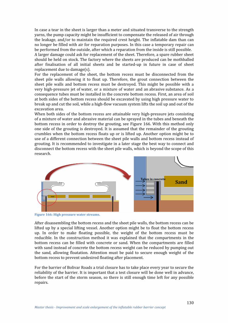
130 Master thesis - Improvement and scale enlargement of the inflatable rubber barrier concept
In case a tear in the sheet is larger than a meter and situated transverse to the strength yarns, the pump capacity might be insufficient to compensate the released of air through the leakage, and/or to maintain the required crest height. The inflatable dam than can no longer be filled with air for reparation purposes. In this case a temporary repair can be performed from the outside, after which a reparation from the inside is still possible. A larger damage could ask for replacement of the sheet. Therefore, a spare rubber sheet should be held on stock. The factory where the sheets are produced can be mothballed after finalisation of all initial sheets and be started-up in future in case of sheet replacement due to damage(s). For the replacement of the sheet, the bottom recess must be disconnected from the sheet pile walls allowing it to float up. Therefore, the grout connection between the sheet pile walls and bottom recess must be destroyed. This might be possible with a very high-pressure jet of water, or a mixture of water and an abrasive substance. As a consequence tubes must be installed in the concrete bottom recess. First, an area of soil at both sides of the bottom recess should be excavated by using high pressure water to break up and cut the soil, while a high-flow vacuum system lifts the soil up and out of the excavation area. When both sides of the bottom recess are attainable very high-pressure jets consisting of a mixture of water and abrasive material can be sprayed in the tubes and beneath the bottom recess in order to destroy the grouting, see Figure 166. With this method only one side of the grouting is destroyed. It is assumed that the remainder of the grouting crumbles when the bottom recess floats up or is lifted up. Another option might be to use of a different connection between the sheet pile walls and bottom recess instead of grouting. It is recommended to investigate in a later stage the best way to connect and disconnect the bottom recess with the sheet pile walls, which is beyond the scope of this research.
Figure 166: High pressure water streams.
After disassembling the bottom recess and the sheet pile walls, the bottom recess can be lifted up by a special lifting vessel. Another option might be to float the bottom recess up. In order to make floating possible, the weight of the bottom recess must be reducible. In the construction method it was explained that the compartments in the bottom recess can be filled with concrete or sand. When the compartments are filled with sand instead of concrete the bottom recess weight can be reduced by pumping out the sand, allowing floatation. Attention must be paid to secure enough weight of the bottom recess to prevent undesired floating after placement. For the barrier of Bolivar Roads a trial closure has to take place every year to secure the reliability of the barrier. It is important that a test closure will be done well in advance, before the start of the storm season, so there is still enough time left for any possible repairs.

131 Master thesis - Improvement and scale enlargement of the inflatable rubber barrier concept
9.7 Costs The costs of the IRB for Bolivar Roads are determined based on the cost calculation of Ramspol. The investment costs for the barrier of Ramspol were € 50 million32. In addition, work had to be done to compensate the environmental effects of the construction of the inflatable dam. For the total project costs of Ramspol a credit is made available of more than € 70 million, which is a factor 1.4. In general, the two largest expenses of the investment costs of an IRB consist of the sheet and the foundation. The sheet of the dam is an unique element of the project and cannot be considered as standard building material due to dimensions. It can be expected that the number of manufacturers being able to produce such a sheet is limited. Altogether, it is difficult to define the accurate price for the sheet of an inflatable dam. Based on data from the Ramspol barrier a price of € 1200/m2 has been chosen for the sheet. The sheet that is required for Bolivar Roads must resist high loads, which might be cost-increasing. However, the major part of the sheet costs arises from the rubber compound and production of the sheet; opposite, the reinforcement costs are relatively low.33 Therefore, the costs of the sheet for Bolivar Roads will not be much higher. For now it is assumed that the price of the sheet is € 2000/m2.34 In Table 32 the total sheet surface of the Bolivar Roads barrier (21 sheets) is calculated. See Appendix 22 for the calculation in more detail. Amount Crest height Sheet surface per inflatable dam Total surface sheet 3 19 m 5370 m2 16110 m2 9 17 m 4630 m2 41670 m2 9 10 m 2646 m2 23814 m2
81594 m2 Table 32: Sheet surface Bolivar Roads barrier.
The conservative estimated lifetime of the sheet is at least 25 years. Based on the experience with Ramspol and additional periodically destructive strength tests it might be possible to demonstrate a sheet lifetime of approximately 50 years. This is a huge cost savings potential. For now it is assumed that the lifetime of the sheet is 25 years and the life time of the barrier 100 years. Therefore, 4 times 21 sheets are needed during the expected lifetime of the barrier of Bolivar Roads. Also a spare sheet is required, to keep on stock for emergencies. For the barrier of Ramspol no spare sheet is kept on stock. See Table 33 for the cost calculation of the sheet.
Sheet surface (25 yr)
Sheet surface (100 yr)
Spare sheet surface
Total sheet surface
Costs sheet (100 yr)
Ramspol 6000 m2 24000 m2 - 24000 m2 €28,800,000 Bolivar Roads 81600 m2 326400 m2 5370 m2 331770 m2 €663,540,000
Bolivar Roads With 2% price inflation per yr
81600 m2 326400 m2 5370 m2 331770 m2 €1,601,618,411
Table 33: Cost calculation sheet Ramspol versus Bolivar Roads.
32 Groot Salland Waterschap 33 Bouwdienst Rijkwaterstaat, Kennis- en Ervaringsdocument Balgkering Ramspol, December 2007, p. 20. 34 Dunlop

132 Master thesis - Improvement and scale enlargement of the inflatable rubber barrier concept
Based on the investment figures of Ramspol the sheet costs (over 100 year without a price increase) cover 50%35 of the total investment costs. As a result the sheet costs for a period of 25 years will be 20% of the total investment costs. When this is also the case for the barrier of Bolivar Roads the total investment costs will be which is €0.35 million per metre barrier length. Compensation for the possible negative and environmental effects concerning the construction of the inflatable dam is excluded. The costs during its lifetime are much larger than only the investment costs mainly due to the sheet replacement every 25 years (3 times € 163 million); the maintenance costs of inflatable dams are relatively cheap. For the calculation of the total costs during the barriers lifetime a price increase of the rubber sheet (€2000) should be included. With a price increase of 2% per year the total costs of the sheet will be €1,601,618,411. = €1,601,618,411 Therefore, the total costs during its lifetime will be minimal , which is € 0.92 million per metre barrier length. The actual costs for Bolivar Roads might be lower, because of the following reasons:
No tension piles are needed under the barrier; The sheet does not need to be transported; The lifetime of the sheet might be longer than 25 years; Lower sheet costs due to the large amount (discount); No abutments need to be realized in the waterway.
Based on traditional barriers: Maeslant barrier, Hartel barrier, Easternscheldt barrier, Ramspol barrier, Ems-barrier, Thames-barrier and the Nakdong-river barrier the present investment cost per cubic meter of barriers is € 31,000 /m3.36 When for Bolivar Roads was chosen for a traditional barrier with a height of 19 m and a head of 7 m the investment costs will be € 4.1 million per metre barrier length. The IRB for Bolivar Roads costs ‘only’ € 0.92 million per metre barrier length (i.e. 80% less costs). Cost comparison with proposed barrier for Verrazano Narrows At this moment the proposed design for the Bolivar Roads barrier (see chapter 5) is the same barrier as the proposed barrier for the Bay of New York, Verrazano Narrows; a combination of the Eastern Scheldt barrier in Zeeland and the Maeslantkering in Rotterdam. Arcadis presented plans to build the storm surge barrier with a total length of 1820 m for Verrazano Narrows. The total costs are estimated at € 4.9 billion, which is equivalent to € 2.7 million per metre barrier length, which is much more compared to the costs of the inflatable barrier design of this research.
35 Bouwdienst Rijkswaterstaat, Aandachtspunten Balgstuwen, (NIO-A-N-96085), July 1997 36 A. van der Toorn, Spreadsheet Cost index numbers barriers

133 Master thesis - Improvement and scale enlargement of the inflatable rubber barrier concept
10 Conclusion and recommendations In the first section of this chapter the conclusions of this study are presented. In the second section several recommendations are given.
10.1 Conclusions In this research the improvement and scale enlargement of inflatable rubber storm surge barriers based on experiences with the inflatable rubber barrier of Ramspol, near Kampen, the Netherlands is investigated. The following conclusions are drawn about scale enlargement and points of improvement of inflatable barriers:
To date the largest (in height) realized IRB is the barrier of Ramspol. As a result of this study it can be concluded that larger inflatable barriers are feasible. This is justified by means of the Bolivar Roads (Texas, USA) case study. This location requires a storm surge barrier with a crest height of 19 m, which is ca. 2.3 times higher than the crest height of the inflatable dam of Ramspol. With a water head difference of 7 m it is calculated that a static membrane force of 665 kN/m will be present in the middle part of the Bolivar Roads dam, which is about 3.3 times higher than the static membrane force of Ramspol. Due to stress concentrations in the sheet and dynamic loads the peak membrane force can be 5 times higher than the static membrane force. Such high loads can still be withstand by already existing rubber materials.
A critical phenomenon of the inflatable dam of Ramspol is the appearance of folds and peak stresses in the sheet when the dam is inflated. Due to these high stresses, the design membrane force for Ramspol is almost 5 times larger than the static force. The folds and peak stresses are caused by the enlargement of the sheet in longitudinal direction, which is necessary to provide enough freedom of movement (i.e. leeway) of the dam around the transition to the abutments to prevent a load transfer in longitudinal direction towards the abutments.
Another critical phenomenon of the inflatable dam of Ramspol is the storing of the rubber sheet in the bottom recess. Sometimes after the storing of the sheet a protruding flap of the sheet remains, which can be hit and damaged by e.g. a passing vessel. Flap occurring is caused by too quick drainage of the internal water compared to the discharged air; for the deflation of the Ramspol barrier only water pumps are used, the air is pushed out of the dam due to the external water pressure.
In this report two inflatable rubber barrier designs are presented for the Bolivar Roads case study. In both designs the critical points were addressed.
Design 1: 7 pcs inflatable dams with the shape of an ellipsoid connected to abutments with a small angle of inclination.
Design 2: 21 pcs chained ellipsoid-shaped inflatable dams without abutments. Design 2 results in the largest reduction of folds and peak stresses in the sheet compared to design 1 and Ramspol, due to the absence of the abutment connection. Design 2 has also a higher reliability due to the larger number of relatively small inflatable dams which is possible due to absence of the abutments. Therefore, design 2 (see heading: New design) was the chosen option for the final design of the storm surge barrier of Bolivar Roads.

134 Master thesis - Improvement and scale enlargement of the inflatable rubber barrier concept
The following conclusions are drawn with respect to the new design:
Due to the absence of the abutment connection the load will be mainly transferred in the circumferential direction of the inflatable dam. Therefore, no enlargement of the sheet and no double-waved clamping structure are needed. As a result it is concluded that no or only small folds and stress concentrations will occur in the sheet. This is also partly due to the ellipsoid shape of the dam.
Due to the new design a better force transfer in the sheet will occur, ensuring low peak membrane forces and thus a small multiplication factor (< 5) between the static and peak membrane forces, which makes scale enlargement more feasible. Although the multiplication factor between these two membrane forces is limited, the membrane forces of large inflatable dams (height: 19 m) are still very high (> 1000 kN/m) and, therefore, a sheet material with a high tensile strength is required. A reinforced rubber sheet that can resist very high loads is developed for a conveyor belt by Dunlop; e.g. a rubber sheet with seven plies and a tensile strength of ca. 4000 kN/m. The comparison between the sheet of the inflatable dam and the conveyor belt is made to indicate that materials which can withstand very high loads are already existing on the market.
Another advantage of an inflatable dam without an abutment connection is that no intermediate abutments are needed, resulting in minimal navigation and water flow disturbance and less visual pollution when the dam is deflated. In addition, the ellipsoid shape of the dam and the absence of the connection with the abutments ensures that the storing of the sheet is much easier.
The best procedure to deflate the inflatable dam is to blow first the air off and then pump the water out (two-step procedure). Therefore, in the new design tubes to blow off air are attached to the sheet, which ensures that first all the internal air is out, followed by the water. Also transponders are embedded in the sheet, allowing a sensor to detect whether the sheet is well-distributed.
The application of several chained ellipsoid-shaped inflatable dams in large water depths in order to control flood is technically and economically feasible. The inflatable barrier for Bolivar Roads costs ‘only’ € 0.92 million per metre barrier length, while traditional barriers which are loaded by a water head of 7m and have a height of 19 m will cost € 4.1 million per metre barrier length.
New design In this thesis a new design of an IRB is developed in order to improve the inflatable barrier concept. The re-designed barrier consists of multiple chained ellipsoid-shaped inflatable dams, where none of the dams have a connection with abutments. Due to the absence of these connections water leakage between the dams will occur, which is not a problem since a 100% closure is not demanded for the Bolivar Roads barrier. Each inflatable dam has the shape of an ellipsoid in the end parts, and a half cylindrical design (cross-section), like a ‘normal’ inflatable dam, in the middle part. The curvature of the ellipsoid part has an influence on the amount of water leakage between the dams. A dam with a larger curvature results in smaller water leakage. For storm surge barriers a high reliability is essential. A higher reliability of the inflatable barrier can be obtained by chaining several smaller length inflatable dams (<100 m) instead constructed of one long dam (>100 m). When an inflatable dam is connected to abutments a small length of the dams results automatically in more abutments, which might disturb navigation and water flow. Because the new design does not require abutments, a smaller length of the dams to increase the reliability constitutes no problem.

135 Master thesis - Improvement and scale enlargement of the inflatable rubber barrier concept
10.2 Recommendations In this thesis specifically the IRB at the Bolivar Roads location was studied, but the new barrier design presented can also be applied at other locations where (large-sized) barriers are needed and some water leakage is allowed. Before the new barrier design can be applied in practice, more accurate studies must be performed. In this thesis no finite element calculations and hydraulic tests have been performed. For further analysis it is important to perform such calculations and tests in order to obtain a more accurate transfer of the forces in the sheet and foundation of the proposed new type IRB. For the calculation of the static membrane forces of the Bolivar Roads barrier only 2-D calculations have been made, where the weight of the sheet was excluded. The peak membrane forces were not calculated, but assumed based on the design formula of Ramspol. With a more accurate determination of the forces in the sheet the exact value of the multiplication factor between the static and peak membrane force for the ellipsoid-shaped inflatable dam of Bolivar Roads can be determined. For the foundation of the IRB also solely 2-D calculations were performed in order to determine the dimensions of the bottom recess. Therefore, a more precise calculation should be performed, taking into account e.g. the spread of forces in multiple directions. Therefore, it is recommended to perform 3-D FEM calculations. The dynamic behaviour of the structure has also been excluded from this study. For further analysis it is important to study the vibrations of the inflatable dam due to waves and water flow through the gaps between the dams. Several other loads besides wave loads have been neglected in this research, because it was assumed that these loads are very small compared to the hydrostatic water pressure load. This concerns: loads due to sloshing, loads as a result of strain in the structure, loads as a result of temperature, loads in the longitudinal direction of the membrane, and loads due to a negative pressure at the downstream water side. Also wave impacts were excluded, because it was assumed that the rounded shape of the inflatable dam ensures that water is not trapped. For future analyses it is important that these loads are additionally taken into account. For the new design of the IRB a bottom recess was developed in order to improve the storage of the sheet. For further analysis it is important to test, by using scale models, whether this bottom recess indeed results in better sheet storing and if more improvements can be made. Also, it should be tested whether tubes attached to the sheet in order to blow off air will ensure the best procedure of deflation. In this thesis it is assumed that the failure probability of each category of the Bolivar Roads barrier will be equal to the failure probability of the categories of the Ramspol barrier. It is therefore recommended to calculate the exact failure probabilities of the Bolivar Roads (or a comparable) barrier. With the new design water leakage will occur between the dam; 5% (without waves included) of waterway is open. It must be investigated if it is possible to place the ellipsoid shaped dams against each other in order to limit the water leakage.

136 Master thesis - Improvement and scale enlargement of the inflatable rubber barrier concept
When the new design of the IRB will be applied for Bolivar Roads more detailed investigation about this location should be performed:
For the calculation of the membrane forces for Bolivar Roads an upstream water level of 19 m and a downstream water level of 12 m is assumed. More research needs to be done to determine the occurring water levels.
Due to the ellipsoid shape of the inflatable dam and the absence of the connection with abutments water leakage will occur. It must be calculated more precisely how much water leakage is permitted for Bolivar Roads and how much water leakage will occur.
For now on a simple (concept) calculation has been made for the water velocities on the bed and the associated sediment transport. With computer programs the exact water and sediment behaviour due to the barrier must be calculated. Also a more accurate determination of the bed protection should be performed.
A more extensive soil investigation must take place for Bolivar Roads concerning the foundation calculations. Thereby, also some conclusions can be drawn about the risk of bursting up and heave.
For the sheet of the inflatable dam a material with high tensile strength is needed. In this thesis a conveyor belt of Dunlop was used to indicate that materials which can withstand very high loads are already available on the market. For the barrier of Bolivar Roads the exact composition of the sheet material of the inflatable dam must be determined.
A more accurate calculation of the investment and maintenance costs should be performed. For the cost calculation it is important to determine the exact lifetime of the sheet. In order to compute this, periodically destructive strength tests should be performed on the sheet.

137 Master thesis - Improvement and scale enlargement of the inflatable rubber barrier concept
References Articles: Baars, van S., Bezuyen, K.G., Colenbrander, W., Kuijper, H.K.T., Molenaar, W.F., Spaargaren, C., Vrijling, J.K., Course: Hydraulic Structures 1, Lecture notes CT3330 – General, November 2009, TU Delft Bittner, R. and Miles, W., Lock Review (Braddock) - PIANC - WG29 Bouwdienst Rijkwaterstaat; Kennis- en Ervaringsdocument Balgkering Ramspol, December 2007 Bouwdienst Rijkwaterstaat en WL| Delft Hydraulics, Hydraulische aspecten van balgstuwen en balgkeringen, Bouwdienst Rijkswaterstaat, December 2005; Bouwdienst Rijkswaterstaat, Aandachtspunten Balgstuwen, (NIO-A-N-96085), July 1997 Cats, M., Klotsen in een Balgkering, TU Delft, April 1998 Cox, C., Davis, J., Hennigan, S., Robichaux, L., Bolivar Roads Sector Gates, April 2013 Deltares, D-Geo Stability, Slope stability software for soft soil engineering, Manual Version 10 Dirkmaat, A., Voorlopig Ontwerp Balgkering "Het Spui", Hogeschool Utrecht, August 2011 Dorreman, J., Balgstuwen gevuld met luchten/ of met water, TU Delft, May 1997 Dunlop Conveyor Belting, Technical Manual, 11-07-2011 Michelin Aircraft Tire, Engineering Data, Reference: #MAT-DB-01 Rev.A Pusadkar, S. and Bhatkar, T., Behaviour of Raft Foundation with Vertical Skirt Using Plaxis 2d, June 2013 Ruijs, M., The effects of the “Ike Dike” barriers on Galveston Bay, TU Delft, June 2011 Voorendt, M.Z., Molenaar, W.F., Bezuyen K.G., Course: Hydraulic Structures 1, Lecture notes CT3330 – Caissons, February 2011, TU Delft Ziel, van der F., Movable water barrier for the 21st century, TU Delft, September 2009

138 Master thesis - Improvement and scale enlargement of the inflatable rubber barrier concept
Internet sources: Phoenix News by Catherine Holland, Rubberized dam breaks at Tempe Town Lake, July 2010 http://www.azfamily.com/news/local/Rubberized-dam-breaks-at-Tempe-Town-Lake-98917614.html The Seattle Times by Mark Carlson, Officials rule out foul play in Arizona dam break, July 2010 http://seattletimes.com/html/nationworld/2012411274_apusarizonadambreak.html The Sydney Morning Herald, by Barbeler, D. and Dunlevy, G., Mining town hit by deadly weir tragedy, November 2008 http://news.smh.com.au/national/mining-town-hit-by-deadly-weir-tragedy-20081124-6eyn.html http://en.wikipedia.org/wiki/Inflatable_rubber_dam#cite_note-2 http://kenguide.camstreams.com/ http://www.blueoceantackle.com/yokohama_fenders.htm www.goodyearblimp.com Powerpoint presentation:
Presentation Probabilistic Asset Management Storm Surge Barrier Ramspol, 25-04-2013

139 Master thesis - Improvement and scale enlargement of the inflatable rubber barrier concept
List of Figures Figure 1: Design 1 for Bolivar Roads: Ellipsoid-shaped inflatable dams connected to abutments. 3 Figure 2: Design 2 for Bolivar Roads: Multiple ellipsoid shaped inflatable dams without a connection. 3 Figure 3: Inflatable rubber barrier Ramspol. 7 Figure 4: Location of the inflatable rubber barrier Ramspol. 8 Figure 5: Map of Ramsdiep and Ramsgeul. 8 Figure 6: Outline report. 11 Figure 7: Overview chapter 2. 12 Figure 8: One-sided clamped rubber sheet (Figure: Rijkswaterstaat and WL | Delft Hydraulics). 12 Figure 9: Left: two-sided clamped rubber sheet, Right: one-sided clamped rubber sheet. 12 Figure 10: Two-sided clamped rubber sheet (Figure: Rijkswaterstaat and WL | Delft Hydraulics). 13 Figure 11: Two sided clamped inflatable dam (Figure: Rijkswaterstaat and WL | Delft Hydraulics). 15 Figure 12: Force transfer inflatable rubber barrier with bottom recess. 16 Figure 13: Forces on air and water inflatable dam. 16 Figure 14: Load distribution over both clamping lines (Figure: Rijkswaterstaat and WL). 17 Figure 15: Pressure air filled inflatable dam (Figure: Rijkswaterstaat and WL | Delft Hydraulics). 18 Figure 16: Pressure water filled inflatable dam (Figure: Rijkswaterstaat and WL | Delft Hydraulics). 18 Figure 17: Pressure water and air filled inflatable dam (Rijkswaterstaat + WL | Delft Hydraulics). 18 Figure 18: Pressure difference along sheet (Dirkmaat). 19 Figure 19: Varying internal air and water pressure of water and air filled inflatable dam (Dirkmaat). 19 Figure 20: Forces in an element with length dS* (Left: Parbery, 1976) 20 Figure 21: Forces in an element (Figure Dorreman) 21 Figure 22: V-notch during inflation of the inflatable dam of Ramspol. 23 Figure 23: Cross-section of the water filled inflatable dam during inflation. 23 Figure 24: Sloshing in a water and air filled inflatable dam (Figure: Dorreman). 25 Figure 25: Overview chapter 3. 26 Figure 26: Three identical inflatable dams of Ramspol. 26 Figure 27: Barrier of Ramspol. 26 Figure 28: Rubber sheet reinforced with aramid fabric (Figure: Rövekamp). 28 Figure 29: Rubber sheet reinforced with aramid fabric. 28 Figure 30: Sheet for the inflatable dam of Ramspol (Figure: Bouwdienst Rijkwaterstaat). 29 Figure 31: Joint – Cross-section sheet in longitudinal direction (Figure: Bouwdienst Rijkwaterstaat). 29 Figure 32: Unrolled sheet near the final location Ramspol (Photo: Bouwdienst Rijkwaterstaat). 30 Figure 33: Teeth clamp for horizontal part. 30 Figure 34: Small wave clamp for abutment part. 31 Figure 35: Scale model with rotating guide rollers (Photo WL | Delft Hydraulics). 31 Figure 36: Left: fixed corner spacers; Middle: rollers on abutment; Right: rotating corner spacers. 32 Figure 37: Fold formation above abutment in deflated state, Left: scale model, Right: Ramspol. 32 Figure 38: Cross-sections bottom recess, phase 1 of deflation (Figure Jongeling + Rövekamp). 33 Figure 39: Cross-sections bottom recess, phase 2 of deflation (Figure Jongeling + Rövekamp). 33 Figure 40: Cross-sections bottom recess, phase 3 of deflation (Figure Jongeling + Rövekamp). 33 Figure 41: A flap due to not evenly distributed sheet. 33 Figure 42: Inflatable dam with no connection to the abutments. 34 Figure 43: Longitudinal lines in the inflatable dam. 34 Figure 44: Stepwise clamping structure Ramspol. 35 Figure 45: Peak stresses in stepwise clamped sheet above the abutment. 35 Figure 46: Folds in Ramspol barrier (Photo: Bouwdienst Rijkswaterstaat). 35 Figure 47: Failure probability of several failure categories (Presentation Probabilistic Asset Management Storm Surge Barrier Ramspol). 37 Figure 48: Reduction failure probability due to some measures. 37 Figure 49: Barrier of Ramspol. 39 Figure 51: Rubber sheet reinforced with aramid fabric (Figure: Rövekamp). 40 Figure 52: Hurricane Ike path, seawall and barriers (Merrell 2010). 45 Figure 53: Bolivar Roads inlet. 45 Figure 54: Proposed barrier for Bolivar Roads; Left: Verrazano Narrows, Right: Bolivar Roads. 46 Figure 55: Locations for the Bolivar Roads barrier. 46 Figure 56: Bottom profile at the location of the barrier. 47 Figure 57: Sediment Grab at Bolivar Roads. 47 Figure 58: Overview chapter 6. 48 Figure 59: Left: blimp; Right: Yokohama Pneumatic Rubber Fender. 49 Figure 60: Overview chapter 7. 51 Figure 61: Overview paragraph 7.1. 51 Figure 62: Equipment Ramspol located below sea level. 55 Figure 63: Overview paragraph 7.2. 58 Figure 64: Wave load, water pressure and wind load on an inflatable dam. 59 Figure 65: Clear view of the size proportions of the inflatable dam of Ramspol and Bolivar Roads. 61 Figure 66: Occurring situations along the length of the membrane. 63 Figure 67: Process diagram model of the spread sheet. 63 Figure 68: Graphical presentation of membrane, vertical and horizontal forces. 64 Figure 69: Overview paragraph 7.3. 68 Figure 70: Shifting of the inflatable dam. 68 Figure 71: Design of abutment Ramspol (edge of membrane: sheet lies flat on the bottom). 69

140 Master thesis - Improvement and scale enlargement of the inflatable rubber barrier concept
Figure 72: Overlength; Left: straight clamping line, Right: wavy formed clamping line. 69 Figure 73: Tension force in transverse direction; Left: large steps, Right: waves (Rijkswaterstaat). 70 Figure 74: Forces in longitudinal direction; wave clamping structure (Bouwdienst Rijkswaterstaat). 70 Figure 75: Different slopes. Left: side view; Right: top view sheet. 71 Figure 76: Stresses in the sheet. Left: slope of the abutment 45 ; Right: slope of the abutment 75 . 71 Figure 77: Circular clamping lines. 71 Figure 78: A half ellipsoid-shaped inflatable dam attached to the abutments. 72 Figure 79: Left: folds at transition; Right: no folds at transition. 72 Figure 80: No stress concentrations at the transition between the middle section and abutments. 72 Figure 81: Minimum desired freedom of movement, 1: without deformation, 2: with deformation. 73 Figure 82: Deformation of the inflatable dam. 73 Figure 83: Cross section; Left: without deflection, Right: with deflection. 73 Figure 84: Side view ellipsoid-shaped inflatable dam. 74 Figure 85: Several inflatable dams over the estuary width using intermediate abutments. 75 Figure 86: Inflatable dams with an abutment of 20 . 75 Figure 87: Bolivar Roads barrier consisting of 7 inflatable dams, abutment slope of 20 . 75 Figure 88: Several inflatable dams realized over Bolivar Roads with intermediate abutments. 76 Figure 89: Maximum occurring current speed at the Bolivar Roads inlet (Ruijs). 77 Figure 90: Plunging jet. 78 Figure 91: Composition concrete block mattress Eastern Scheldt, the Netherlands. 79 Figure 92: Composition filter mattress Eastern Scheldt. 79 Figure 93: Cross-section barrier foundation Eastern Scheldt. 79 Figure 94: Top view bottom protection barrier Eastern Scheldt. 79 Figure 95: Overview paragraph 7.4. 80 Figure 96: Different shapes of the sheet when stored. 81 Figure 97: Water filled inflatable dam under the influence of flowing water. 81 Figure 98: A part of an inflatable dam with an internal tube for pumping air out. 82 Figure 99: Extra depth of bottom recess needed. 82 Figure 100: Tire of a tar sand truck. 83 Figure 101: Part of the bottom recess with three rows of tires. 83 Figure 102: Distance between the tires. 84 Figure 103: Deflation of the inflatable dam. 84 Figure 104: Left: inflated dam; Right: cross-section deflated dam. 84 Figure 105: Preferred location of the transponders. 85 Figure 106: Bottom profile with proposed dimensions of the inflatable dam. 86 Figure 108: Design 1 Bolivar Roads IRB: ellipsoid-shaped inflatable dams connected to abutments. 87 Figure 109: Overview design 2. 90 Figure 110: Overview paragraph 8.1. 90 Figure 111: Side view ellipsoid-shaped inflatable dam. 91 Figure 112: Bottom profile Bolivar Roads with nine inflatable dams over the total width. 92 Figure 113: Water leakage. 92 Figure 114: Left: Ellipsoid-shaped inflatable dam; Right: Ellipse. 93 Figure 115: Ellipsoid inflatable dam with a small b (b: length ellipsoid part). 93 Figure 116 Bottom profile with proposed dimensions of the inflatable dam 93 Figure 117: Bottom profile with proposed dimensions of the inflatable dam. 94 Figure 118: Comparison of two inflatable dams of Bolivar Roads and Ramspol. 94 Figure 119: Two rows of multiple inflatable dams placed over the width. 95 Figure 120: Wave overtopping and water flow over the inflatable dam with downstream water level. 95 Figure 121: Fin in longitudinal direction of the inflatable dam. 96 Figure 122: Overview paragraph 8.2. 97 Figure 123: Longitudinal cross-section of an inflatable dam with a deep bottom recess. 97 Figure 124: Cross-section of an inflatable dam with a deep bottom recess. 97 Figure 125: Clamping structure placed with an angle at the bottom recess. 98 Figure 126: Wider bottom recess. 98 Figure 127: failure with deflation; Left: folds, Right: asymmetric distribution. 99 Figure 128: Top view inflatable dam with stiffeners. 99 Figure 129: Cross-section inflatable dam with stiffeners. 99 Figure 130: Top view inflatable dam; Left: rectangular bottom recess, Right: tapered bottom recess. 100 Figure 131: Bottom recess with clamping line. 100 Figure 132: Bottom profile with proposed dimensions of the inflatable dam. 101 Figure 133: Design 2 Bolivar Roads IRB: Multiple ellipsoid-shaped inflatable dams over the width. 101 Figure 134: Comparison inflatable dam Bolivar Roads and Ramspol. 102 Figure 135: Deflated sheet in a wide bottom recess. 102 Figure 136: Overview chapter 9. 104 Figure 137: Bottom profile with proposed dimensions of the inflatable dam. 104 Figure 138: Cross-section largest inflatable dam of Bolivar Roads barrier (loaded). 105 Figure 140: Water leakage. 106 Figure 141: Bottom recess with position of the dimensions. 106 Figure 142: Loads acting on the bottom recess during floating. 108 Figure 143: Tension force divided in a horizontal and vertical clamping force. 108 Figure 144: Loads acting on the bottom recess (stationary situation). 109 Figure 145: Ballasted cofferdam on top of the top slabs for maintenance. 109 Figure 146: Depth profile Bolivar Roads with transport direction and end location (largest recess). 113 Figure 147: Floating element (Hydraulic Structures Caissons). 114

141 Master thesis - Improvement and scale enlargement of the inflatable rubber barrier concept
Figure 148: Passive and active zone; Left: without sheet pile walls; Right: with sheet pile walls. 116 Figure 149: Cross-section bottom recess with dimensions to prevent floating. 117 Figure 150: Bottom recess with holes in the bottom slab to reduce weight. 117 Figure 151: Prandtl and Brinch Hansen. 119 Figure 152: Bottom profile after excavation. 121 Figure 153: Bottom recesses placed in soil. 123 Figure 154: Concrete apron to one end of the bottom recess. 123 Figure 155: Options for the location of the construction dock. 124 Figure 156: Cross-section bottom recess Bolivar Roads barrier. 124 Figure 157: Reinforcement in circumferential direction. 125 Figure 158: Overlength for clamping. 125 Figure 159: Teeth clamp. 126 Figure 160: Clamping structure on bottom recess option 1. 126 Figure 161: Clamping structure on bottom recess option 2. 126 Figure 162: Extra piece of rubber in clamping structure. 127 Figure 163: Ballast and land bottom recess. 128 Figure 165: Entering an airlock. 129 Figure 166: High pressure water streams. 130
List of Tables Table 1: Considerations filler. ..................................................................................................................................................................................... 14 Table 2: Internal pressure. ........................................................................................................................................................................................... 21 Table 3: External pressure. .......................................................................................................................................................................................... 21 Table 4: Resultant pressure on sheet. ...................................................................................................................................................................... 21 Table 5: Stiffness properties of the sheet materials applied in the scale model. .................................................................................... 27 Table 6: Factors of the design formula for Ramspol........................................................................................................................................... 36 Table 7: Data IRB Ramspol. .......................................................................................................................................................................................... 39 Table 8: Circumferential length and base width of Ramspol IRB.................................................................................................................. 39 Table 9: Factors of the design formula for Ramspol........................................................................................................................................... 40 Table 10: Strength and stiffness properties of the rubber sheet. .................................................................................................................. 41 Table 11: Soil properties Bolivar Roads. ................................................................................................................................................................. 47 Table 12: Differences in boundary conditions. ..................................................................................................................................................... 58 Table 13: Loads on inflatable dam. ........................................................................................................................................................................... 59 Table 14: Wave load compared to hydrostatic load. .......................................................................................................................................... 60 Table 15: Parameters of the Ramspol and initial parameters of Bolivar Roads barrier. ..................................................................... 61 Table 16: Applying equations (Dorreman, 1997). .............................................................................................................................................. 63 Table 17: Static membrane, vertical and horizontal forces as calculated with spreadsheet approach. ........................................ 64 Table 18: Tension force and crest height of several inflatable dams (1/100 yr).................................................................................... 65 Table 19: Tension force and crest height................................................................................................................................................................ 65 Table 20: Membrane, vertical and horizontal forces of Bolivar Roads barrier. ...................................................................................... 66 Table 21: Elongation at break (Naeff 2009). ......................................................................................................................................................... 67 Table 22: Boundary conditions. .............................................................................................................................................................................. 104 Table 23: Parameters largest IRB of Bolivar Roads........................................................................................................................................ 105 Table 24: Membrane and clamping forces largest IRB of Bolivar Roads. ............................................................................................... 105 Table 25: Shear resistance of the element without shear reinforcement. .............................................................................................. 111 Table 26: Elements thickness bottom recess based on the shear force without shear reinforcement. ...................................... 111 Table 27: Shear resistance of the element with shear reinforcement...................................................................................................... 111 Table 28: Element thickness with shear reinforcement. ............................................................................................................................... 111 Table 29: Thickness of elements bottom recess based on the bending moments. .............................................................................. 112 Table 30: Thickness of elements bottom recess based on the shear forces and bending moments. ........................................... 112 Table 31: Summarized which checks for which phase. .................................................................................................................................. 116 Table 32: Sheet surface Bolivar Roads barrier. ................................................................................................................................................. 131 Table 33: Cost calculation sheet Ramspol versus Bolivar Roads. .............................................................................................................. 131

142 Master thesis - Improvement and scale enlargement of the inflatable rubber barrier concept