feasibility of permeation grouting for constructing ... of permeation grouting for constructing...
TRANSCRIPT
SANDIA REPORT SAND94-0786 • UC-721 Unlimited Release Printed April 1994
Feasibility of Permeation Grouting for Constructing Subsurface Barriers
B. P. Dwyer
Prepared by Sandla National Laboratories Albuquerque, New Mexico 87185 and Livermore, California 94550 for the United States Department of Energy under Contract OE-AC04-94AL85000
Approved for public release; distribution is unlimited.
AST Eft SF2900Q(8-81)
DISTBIBUTtOH OF THIS DOCUMENT IS OrlLlMlfcfi
5?T
Issued by Sandia National Laboratories, operated for the United States Department of Energy by Sandia Corporation. NOTICE: This report was prepared as an account of work sponsored by an agency of the United States Government. Neither the United States Government nor any agency thereof, nor any of their employees, nor any of their contractors, subcontractors, or their employees, makes any warranty, express or implied, or assumes any legal liability or responsibility for the accuracy, completeness, or usefulness of any information, apparatus, product, or process disclosed, or represents that its use would not infringe privately owned rights. Reference herein to any specific commercial product, process, or service by trade name, trademark, manufacturer, or otherwise, does not necessarily constitute or imply its endorsement, recommendation, or favoring by the United States Government, any agency thereof or any of their contractors or subcontractors. The views and opinions expressed herein do not necessarily state or reflect those of the United States Government, any agency thereof or any of their contractors.
Printed in the United States of America. This report has been reproduced directly from the best available copy.
Available to DOE and DOE contractors from Office of Scientific and Technical Information PO Box 62 Oak Ridge, TN 37831
Prices available from (615) 576-8401, FTS 626-8401
Available to the public from National Technical Information Service US Department of Commerce 5285 Port Royal RD Springfield, VA 22161
NTIS price codes Printed copy: A03 Microfiche copy: A06

DISCLAIMER
Portions of this document may be illegible in electronic image products. Images are produced from the best available original document.
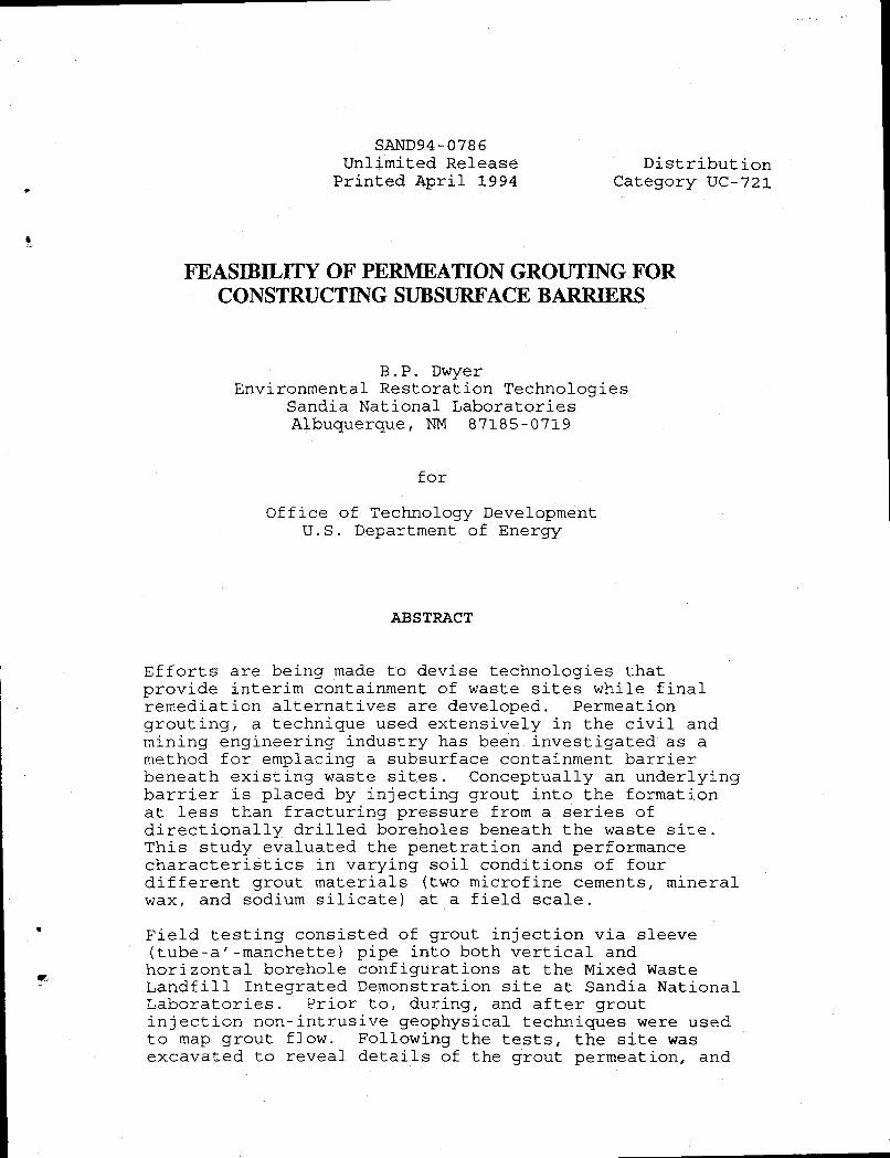
SAND94-0786 Unl imited Release Distribution Printed April 1994 Category UC-721
FEASIBILITY OF PERMEATION GROUTING FOR CONSTRUCTING SUBSURFACE BARRIERS
B.P. Dwyer Environmental Restoration Technologies
Sandia National Laboratories Albuquerque, NM 87185-0719
for Office of Technology Development
U.S. Department of Energy
ABSTRACT
Efforts are being made to devise technologies that provide interim containment of waste sites while final remediation alternatives are developed. Permeation grouting, a technique used extensively in the civil and mining engineering industry has been investigated as a method for emplacing a subsurface containment barrier beneath existing waste sites. Conceptually an underlying barrier is placed by injecting grout into the formation at less than fracturing pressure from a series of directionally drilled boreholes beneath the waste site. This study evaluated the penetration and performance characteristics in varying soil conditions of four different grout materials (two microfine cements, mineral wax, and sodium silicate) at a field scale.
Field testing consisted of grout injection via sleeve (tube-a'-manchette) pipe into both vertical and horizontal borehole configurations at the Mixed Waste Landfill Integrated Demonstration site at Sandia National Laboratories. Prior to, during, and after grout injection non-intrusive geophysical techniques were used to map grout flow. Following the tests, the site was excavated to reveal details of the grout permeation, and
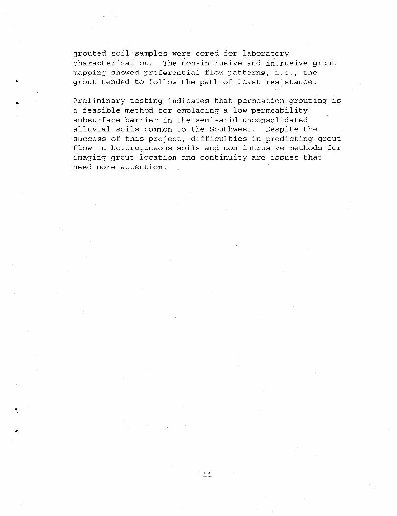
grouted soil samples were cored for laboratory characterization. The non-intrusive and intrusive grout mapping showed preferential flow patterns, i.e., the grout tended to follow the path of least resistance.
Preliminary testing indicates that permeation grouting is a feasible method for emplacing a low permeability subsurface barrier in the semi-arid unconsolidated alluvial soils common to the Southwest. Despite the success of this project, difficulties in predicting grout flow in heterogeneous soils and non-intrusive methods for imaging grout location and continuity are issues that need more attention.
ii
TABLE OF CONTENTS Page
LIST OF TABLES iv LIST OF FIGURES v NOMENCLATURE vi INTRODUCTION 1
Statement of the Problem 1 Approach 2 Nonintrusive Verification 2
RELATED RESEARCH 3 FIELD EXPERIMENTS .' 3
Site Geology 3 Materials and Methods 5
Phase 1 5 Verification 9
Phase II 10 Verification 12
DISCUSSION OF RESULTS 12 Phase I 17
Verification 23 Phase II 25
Verification 25 CONCLUSIONS 26 RECOMMENDATIONS FOR FUTURE WORK 27 REFERENCES 28 APPENDIX A 2 9
iii
LIST OF TABLES Table Page 1. Borehole 2 Grout Mix Proportions 9 2 . Phase II, Geophysical Techniques 13 3 . Approximate Relationship Between Hydraulic
Conductivity and Groutability 18 4. Cement Grout Particle Size and Viscosity 18 5 . Permeation Estimates in Various Soils 18 6 . Grouting Parameters 21 7 . Cement Grout Characteristics 22
iv
LIST OF FIGURES Figure Page 1. Southeast Corner of Tech Area III,
Geotechnical Test Range Location 4 2. Phase 1 and 2 Subsurface Barrier Test
Site Plan View 6 3. Tube-a'-manchette Cross Section
Permeation Grouting Method 7 4 . Phase 1 Grout Site Cross Section 8 5. Phase 2 Grout Site Cross Section (Typical) 11 6 . Range of Soils Suitable For Grouting 14 7 . Test Site Particle Size Distribution 15 8. Permeation of Grouts in Different Porous Media 16 9. Phase 1, Borehole 1 - Observed Grout Penetration
Microfine Cement 2 0 10. Crosswell Seismic Velocity Difference
(%) Tomograms 24
v
Nomenclature PR grout penetration radius PAR pneumatic acoustic receiver GPR ground penetrating radar
vi
INTRODUCTION The cleanup of hazardous waste sites is often difficult and sometimes impossible using established technologies, so the accelerated development of interim measures which mitigate contaminant propagation are greatly needed. Within the DOE Complex alone, there are countless sites that require corrective measures, yet proven, regulatory approved remedial techniques are not available. The primary problem associated with these numerous waste sites is the potential for groundwater contamination as mobile waste forms migrate from the original waste site. In the past, wastes were buried or dumped in unlined pits with the idea that the surrounding soil would act as a natural barrier between the waste and the groundwater. It is now known that some of these waste forms are breaking through to the groundwater. Today, additional precautions such as surface caps and subsurface barriers are an integral part of every waste disposal site design, but the question still remains: what can be done with existing waste sites? In response to this problem, the Mixed Waste Landfill Integrated Demonstration (MWLID) at Sandia National Laboratories (SNL) is currently developing mitigation measures that can be employed in three years or less. The technical feasibility of emplacing a barrier beneath a waste site using directionally drilled boreholes and permeation grouting was investigated. The benefits of this emplacement system are: 1) directionally drilled boreholes provide access beneath
a waste site without disturbing the waste; 2) interim containment of contaminants allows time for the
development of remediation options; 3) in the interim, the volume of waste remains fixed; 4) barriers may enhance the effectiveness of in situ
remediation actions; and 5) barrier systems may provide permanent waste containment
Statement of the Problem The installation of vertical subsurface barriers is standard practice in civil and mining engineering, but methods for constructing horizontal barriers in situ have not yet been developed. In the past barriers have typically been constructed in a vertical orientation to eliminate or re-direct the flow of water around engineered structures, e.g., dams, underground excavations, and to improve the mechanical characteristics of soil or rock for the support of structures or slopes. Experience from the civil and mining industry suggests that subsurface barriers have potential applications in the environmental field. Despite the obvious technological similarities between the traditional and proposed applications, the transition requires
1
careful consideration of health and regulatory issues not seen in previous projects. For old waste sites, the problem is to place a containment basin without disrupting the waste. Vertical barrier equipment and technologies must be adapted to emplace horizontal barriers capable of confining leaking waste sites. The primary weakness in all applications of barrier emplacement is the inability of grouting contractors to completely define the extent and nature of the injected materials, i.e., verification of where the barrier material actually went. Although there are not yet specific regulations defining design parameters and performance standards for subsurface barriers placed beneath existing waste sites, it is likely that the regulatory acceptance of any subsurface barrier will depend on the ability to verify the barrier continuity. Approach The approach of this research is to adapt methods proven for constructing vertical subsurface barriers to construction of horizontal subsurface barriers. A field scale demonstration of a subsurface barrier emplacement that embraces a true "SYSTEMS APPROACH" was chosen. A SYSTEMS APPROACH for emplacing a subsurface barrier requires integration of the following technologies:
1)subsurface access techniques, 2)barrier material emplacement technologies, 3)barrier materials, 4}barrier continuity verification techniques, and 5)post barrier emplacement monitoring.
The field demonstration was conducted in two phases. Phase I involved injecting two different ultrafine cementitious grouts in horizontal boreholes. Phase II consisted of injecting an inorganic and organic grout, respectively, in vertical boreholes. Prior to any grouting activities, the site geology was characterized to a depth of 3 0 feet. The primary characteristic of interest was the variation of the soil particle size distribution with depth. The degree of grout permeation is a function of the grout viscosity, grout particle size, and the particle size distribution; which is directly correlated to the soil hydraulic conductivity of the soil to be grouted. The relationship between these parameters is essential in predicting grout flow characteristics, i.e., understanding the design requirements for a permeation grout barrier emplacement.
Nonintrusive Verification Verification of the continuity, location and physical characteristics of a grout barrier is necessary to ensure barrier
2
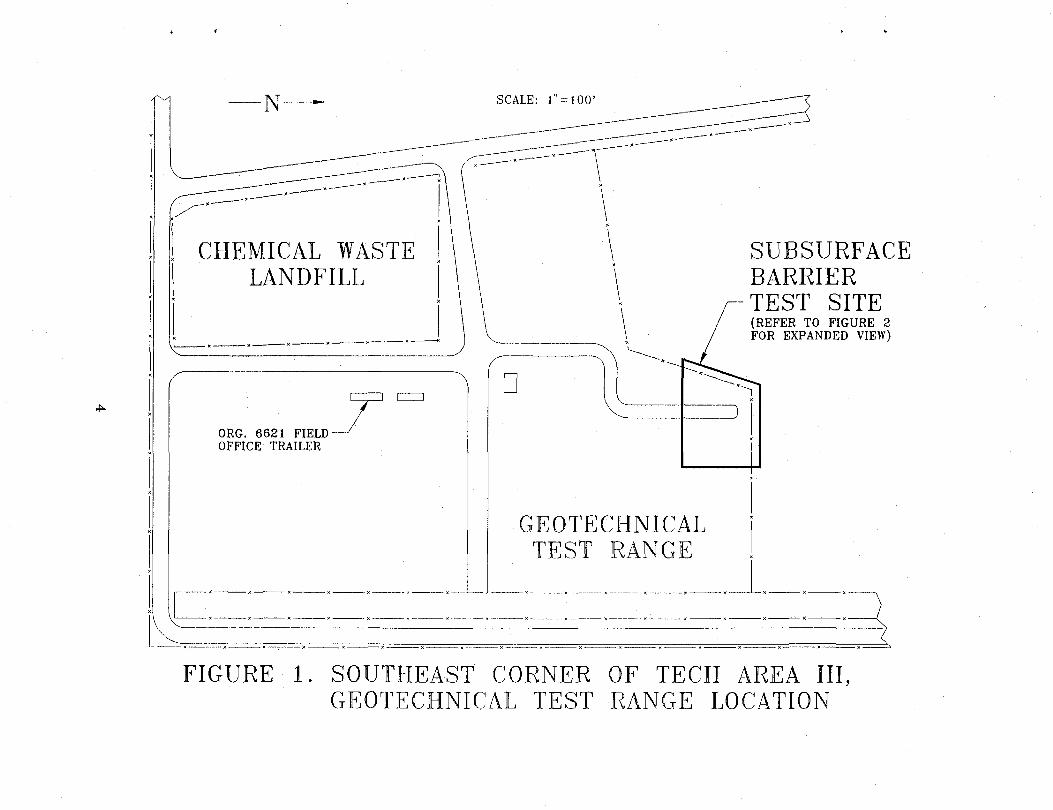
integrity. Techniques for barrier validation can be intrusive or non-intrusive. Nonintrusive methods have the advantage of viewing the subsurface without penetrating the confined waste form. A variety of potential nonintrusive techniques are available for examining a subsurface barrier. Both nonintrusive and intrusive techniques were utilized during this field demonstration. RELATED RESEARCH Prior to this field scale demonstration of permeation grouting Brookhaven National Laboratory (BNL)and Golder Associates, Inc. conducted independent laboratory scale research projects directed at formulating advanced grouting materials to be used for in situ containment of buried chemical waste in the vadose zone of a semi-arid environment. BNL's research focused on superplasticized grouts and soil cements having superior properties and durability to conventional formulations. (Allan, and Kukacka, 1993) Golder Associates, Inc. also performed laboratory evaluation of the performance of two grout materials: a mineral wax - bentonite emulsion developed in Germany; and a glyoxal-modified sodium silicate grout developed in France. The laboratory results are documented in a report entitled Laboratory Test Results for Evaluating the Performance of Montan Wax and Sodium Silicate Barrier Materials in Unconsolidated Soils (Golder Associates, 1993). Both research projects evaluated the emplacement and performance characteristics of the grout materials for creating in situ low permeability barriers in soil samples from the field scale demonstration site at SNL. In addition, mechanical properties such as compressive and flexural strength, and the compatibility of the grout materials with potential hazardous waste materials were evaluated. Data from these lab-scale tests was used to determine grout formulations for the field scale demonstration at SNL. FIELD EXPERIMENTS Site Geology The Subsurface Barrier Emplacement Demonstration Site is located in the Southeast Corner of Technical Area III, Sandia National Laboratories, Albuquerque, New Mexico (Refer to Figure 1). The area typically has a dry, semi-arid climate. The field test site is composed of alternating layers of unsaturated soils which were deposited during flooding episodes. Four vertical sample borings to a depth of 3 0 feet indicated that the soil consists primarily of unconsolidated, unsaturated, silty-sand, with intermittent cobble layers (Appendix A).
3
< '
SUBSURFACE BARRIER TEST SITE (REFER TO FIGURE 2 FOR EXPANDED VIEW)
FIGURE 1. SOUTHEAST CORNER OF TECH AREA III, GEOTECHNICAL TEST RANGE LOCATION

Vertical coreholes in the vicinity of the Mixed Waste and Chemical Waste Landfills show that the near surface deposits vary both vertically and horizontally. The site is approximately 5200 feet above sea level, and 480 feet above regional groundwater. Materials & Methods
Phase I 5 & S Harris and Associates directionally drilled two horizontal boreholes and installed tube-a'-manchette (sleeve) pipe (Figure 2 6 4) casing in the boreholes during drill string withdrawal. Denver Grouting Services, Inc. grouted the sleeve pipe annulus with a relatively weak neat cement/bentonite grout to eliminate preferential flow along the grout pipe annulus during actual grouting operations. Permeation grouting requires grouting the sleeve pipe annulus with a brittle grout material prior to injection with the selected grout(s). The purpose of the annulus grout is to eliminate flow paths along the annular space left between the drilled borehole and the inserted sleeve pipe. After the annulus grout cures the "real" grout is then injected at a pressure sufficient to fracture (perpendicular to the sleeve pipe direction) the relatively weak annulus grout; thereby, directing grout flow radially into the formation at that designated interval only. During actual grouting operations, the Denver Grouting Services, Inc. foreman indicated that the annulus grout may have settled at the low points causing discontinuities and thus partial ineffectiveness of the annular grout. The annulus grout was allowed to cure for 24 hours prior to commencement of actual grouting operations. The tube-a'-manchette casing allows for selective grout injection at designated locations. A packer system located inside the tube-a'-manchette isolates the interval to be grouted. During actual grouting operations, grout is injected at a carefully monitored high pressure in order to fracture the brittle annulus grout. Once the annulus grout fractures (indicated by large pressure drop), the injection pressure is immediately lowered to ensure permeation and not hydrofracturing of•the formation. Denver Grouting Services, Inc. injected the grout materials in one-foot stages using a tube-a-manchette with a double packer system (Figure 3) . Completion of each stage was designated using the following pre-determined cutoff criteria: 1) maximum allowable injection pressure, or 2) maximum grout volume/stage, or 3) grout refusal. 91 gallons of micro-fine cementitious grout was injected in each horizontal borehole. 30 stages, i.e., approximately 30
5
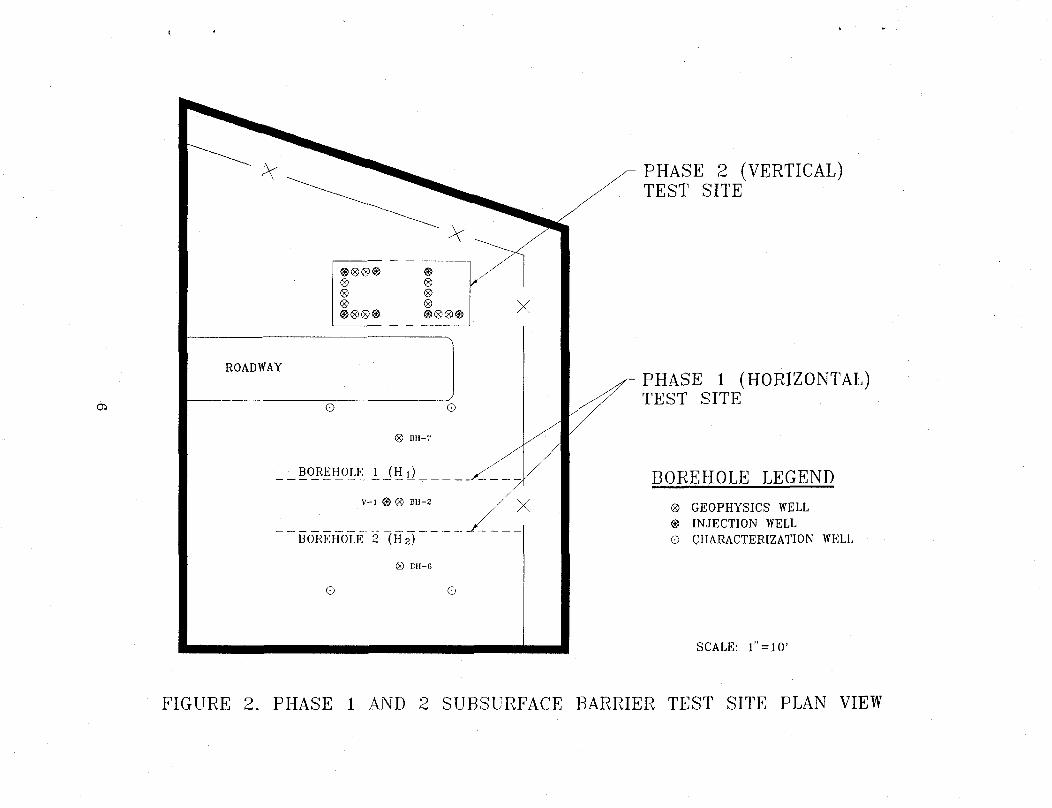
OS
ROADWAY
O G
BH-7
BOREHOLE^ J_ _(H ij ^
V - l ® <g> BU-2
" BOREHOlE 2 "(H 2)
® BII-6
o o
X
PHASE 2 (VERTICAL) TEST SITE
PHASE 1 (HORIZONTAL) TEST SITE
BOREHOLE LEGEND <8> GEOPHYSICS WELL ® INJECTION WELL O CHARACTERIZATION WELL
SCALE: 1" = 10'
FIGURE 2. PHASE 1 AND 2 SUBSURFACE BARRIER TEST SITE PLAN VIEW
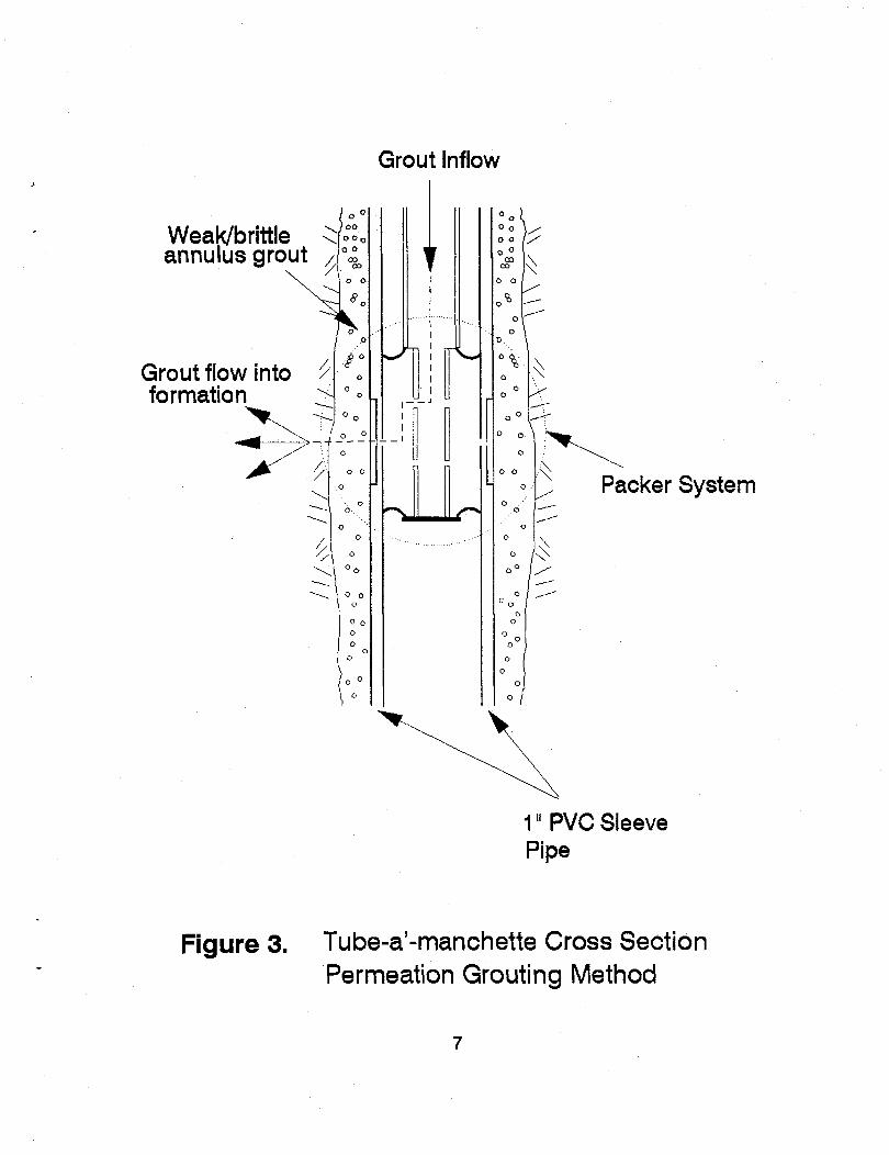
Grout Inflow
Weak/brittle annulus grout ,
Grout flow into formation
Packer System
1" PVC Sleeve Pipe
Figure 3. Tube-a'-manchette Cross Section Permeation Grouting Method
7
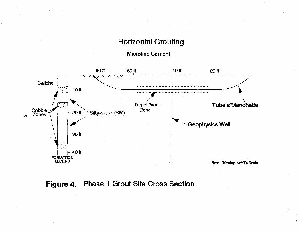
Horizontal Grouting Microfine Cement
80 ft 60 ft r^Oft
Caliche
Cobble J^' oo Zones
KXKXX X^CXX"
10 ft. r 20 ft. x Silty-sand (SM)
- 3 0 ft.
Target Grout Zone
40 ft. FORMAT
LEGEND
20 ft
Tube'a' Manchette
Geophysics Well
Note: Drawing Not To Scale
Figure 4. Phase 1 Grout Site Cross Section.
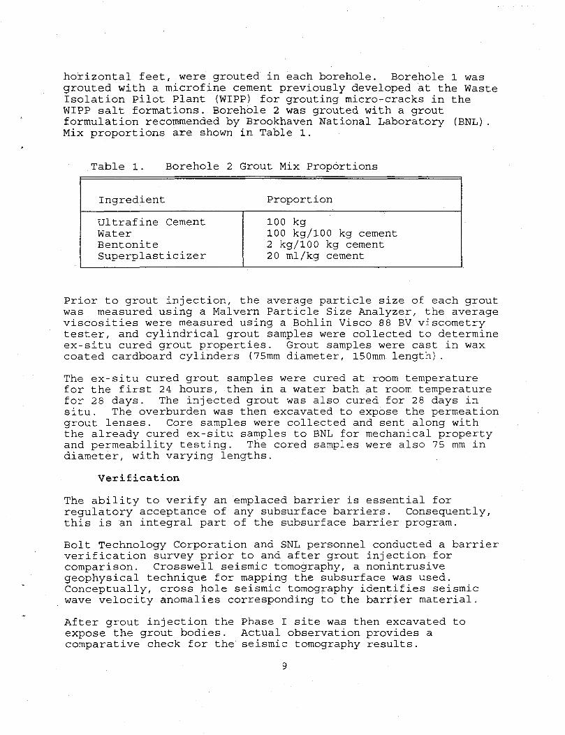
horizontal feet, were grouted in each borehole. Borehole 1 was grouted with a microfine cement previously developed at the Waste Isolation Pilot Plant (WIPP) for grouting micro-cracks in the WIPP salt formations. Borehole 2 was grouted with a grout formulation recommended by Brookhaven National Laboratory (BNL). Mix proportions are shown in Table 1.
Table 1. Borehole 2 Grout Mix Proportions
Ingredient Proportion Ultrafine Cement Water Bentonite Superplasticizer
100 kg 100 kg/100 kg cement 2 kg/100 kg cement 20 ml/kg cement
Prior to grout injection, the average particle size of each grout was measured using a Malvern Particle Size Analyzer, the average viscosities were measured using a Bohlin Visco 88 BV viscometry tester, and cylindrical grout samples were collected to determine ex-situ cured grout properties. Grout samples were cast in wax coated cardboard cylinders (75mm diameter, 150mm length). The ex-situ cured grout samples were cured at room temperature for the first 24 hours, then in a water bath at room temperature for 28 days. The injected grout was also cured for 28 days in situ. The overburden was then excavated to expose the permeation grout lenses. Core samples were collected and sent along with the already cured ex-situ samples to BNL for mechanical property and permeability testing. The cored samples were also 75 mm in diameter, with varying lengths.
Verification The ability to verify an emplaced barrier is essential for regulatory acceptance of any subsurface barriers. Consequently, this is an integral part of the subsurface barrier program. Bolt Technology Corporation and SNL personnel conducted a barrier verification survey prior to and after grout injection for comparison. Crosswell seismic tomography, a nonintrusive geophysical technique for mapping the subsurface was used. Conceptually, cross hole seismic tomography identifies seismic wave velocity anomalies corresponding to the barrier material. After grout injection the Phase I site was then excavated to expose the grout bodies. Actual observation provides a comparative check for the seismic tomography results.
9
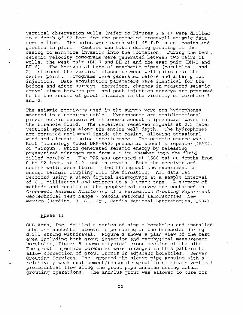
Vertical observation wells (refer to Figures 2 & 4) were drilled to a depth of 52 feet for the purpose of crosswell seismic data acquisition. The holes were cased with 6" I.D. steel casing and grouted in place. Caution was taken during grouting of the casing to minimize invasion into the formation. During the test, seismic velocity tomograms were generated between two pairs of wells; the west pair (BH-7 and BH-2) and the east pair (BH-2 and BH-6) . The horizontal tube-a'-manchette pipes (boreholes 1 and 2) intersect the vertical planes between well pairs near the center point. Tomograms were generated before and after grout injection. Data acquisition parameters were identical for the before and after surveys; therefore, changes in measured seismic travel times between pre- and post-injection surveys are presumed to be the result of grout invasion in the vicinity of borehole 1 and 2 . The seismic receivers used in the survey were ten hydrophones mounted in a neoprene cable. Hydrophones are omnidirectional piezoelectric sensors which record acoustic (pressure) waves in the borehole fluid. The receivers received signals at 0.5 meter vertical spacings along the entire well depth. The hydrophones are operated undamped inside the casing, allowing occasional wind and aircraft noise interference. The seismic source was a Bolt Technology Model DHS-5500 pneumatic acoustic repeater (PAR), or "airgun", which generated seismic energy by releasing pressurized nitrogen gas from a 5 in3 chamber into the fluid filled borehole. The PAR was operated at 1500 psi at depths from 0 to 52 feet, at 1.0 foot intervals. Both the receiver and source wells were fluid filled throughout the experiment to ensure seismic coupling with the formation. All data was recorded using a Bison digital seismograph at a sample interval of 0.1 millisecond and written to a 9-track tape. A summary of methods and results of the geophysical survey are contained in Crosswell Seismic Monitoring of a Permeation Grouting Experiment Geotechnical Test Range - Sandia National Laboratories, New Mexico (Harding, R. S., Jr., Sandia National Laboratories, 1994).
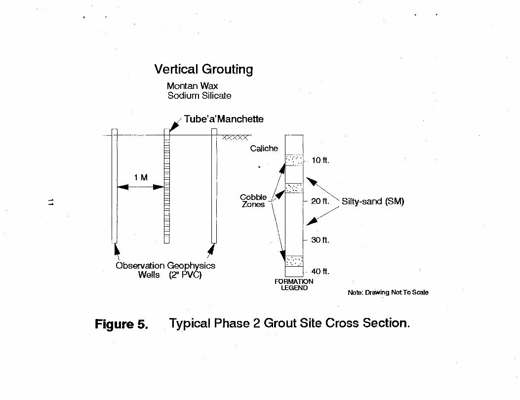
Phase II SHB Agra, Inc. drilled a series of single boreholes and installed tube-a'-manchette (sleeve) pipe casing in the boreholes during drill string withdrawal. Figure 2 shows a plan view of the test area including both grout injection and geophysical measurement boreholes; Figure 5 shows a typical cross section of the site. The grout injection boreholes were arranged in this pattern to allow connection of grout fronts in adjacent boreholes. Denver Grouting Services, Inc. grouted the sleeve pipe annulus with a relatively weak neat cement/bentonite grout to eliminate vertical preferential flow along the grout pipe annulus during actual grouting operations. The annulus grout was allowed to cure for
10
Vertical Grouting Montan Wax Sodium Silicate
1 M
>
/ Tube'a'Manchette
xxxxx Caliche
Cobble _ / • Zones
f Observation Geophysics
Wells (2" PVC) FORMAT ON
10ft.
- 20 ft. x Silty-sand (SM)
30 ft.
40 ft.
Note: Drawing Not To Scale
Figure 5. Typical Phase 2 Grout Site Cross Section.
24 hours prior to commencement of actual grouting operations. Denver Grouting Services, Inc. injected two grout materials: a mineral wax - bentonite emulsion developed in Germany; and a glyoxal-modified sodium silicate grout developed in France (Golder Associates, 1993). The barrier materials were initially identified and evaluated by the International Technology Exchange Project (ITEP) (Golder, 1992), an Office of Technology Development (OTD) funded program directed at identifying foreign technologies applicable to the DOE environmental restoration effort. Grout was injected in one-foot vertical stages using a double packer system located inside the sleeve pipe (Figure 3). Again completion of each stage was designated using the following predetermined cutoff criteria: 1) maximum allowable injection pressure, or 2) maximum grout volume/stage, or 3) grout refusal.
Verification Figures 2 and 5 show plan and profile views of the geophysical wells used during Phase II. Geophysical measurements were taken prior to, during and after grout injection. Variation in soil properties such as electrical conductivity, and the dielectric constant are used to map grout location. The geophysical methods employed during Phase II testing are listed in Table 2. After grout injection, boreholes were drilled to collect soil samples in the Phase II test area. The sample collection was intended to verify information obtained from the geophysical surveys. SHB Agra, Inc. and a Golder geologist drilled and collected the samples using a modified California drive sampler. DISCUSSION OF RESULTS As exemplified in Figures 6 and 8, the literature suggests that permeation grouting with low viscosity grout is appropriate for gravels and sands, but only marginal for silts or clays. Figure 7 summarizes the range of results of particle size distribution analyses on test site soil samples. (Golder,1994) Direct comparison of Figures 6 and 7 indicates that the geologic conditions at the test site are marginal for permeation grouting; however, the soil logs (Appendix A) indicate the presence of higher permeability zones at approximately 8 to 10 ft., and 16 to 17 ft. These layers contain a poorly graded mixture of cobble (3" to 10"), coarse sand and gravel, and silty sand. The groutability of soil is related to the interconnection between adjacent pore spaces in the soil matrix, i.e., the soil
12
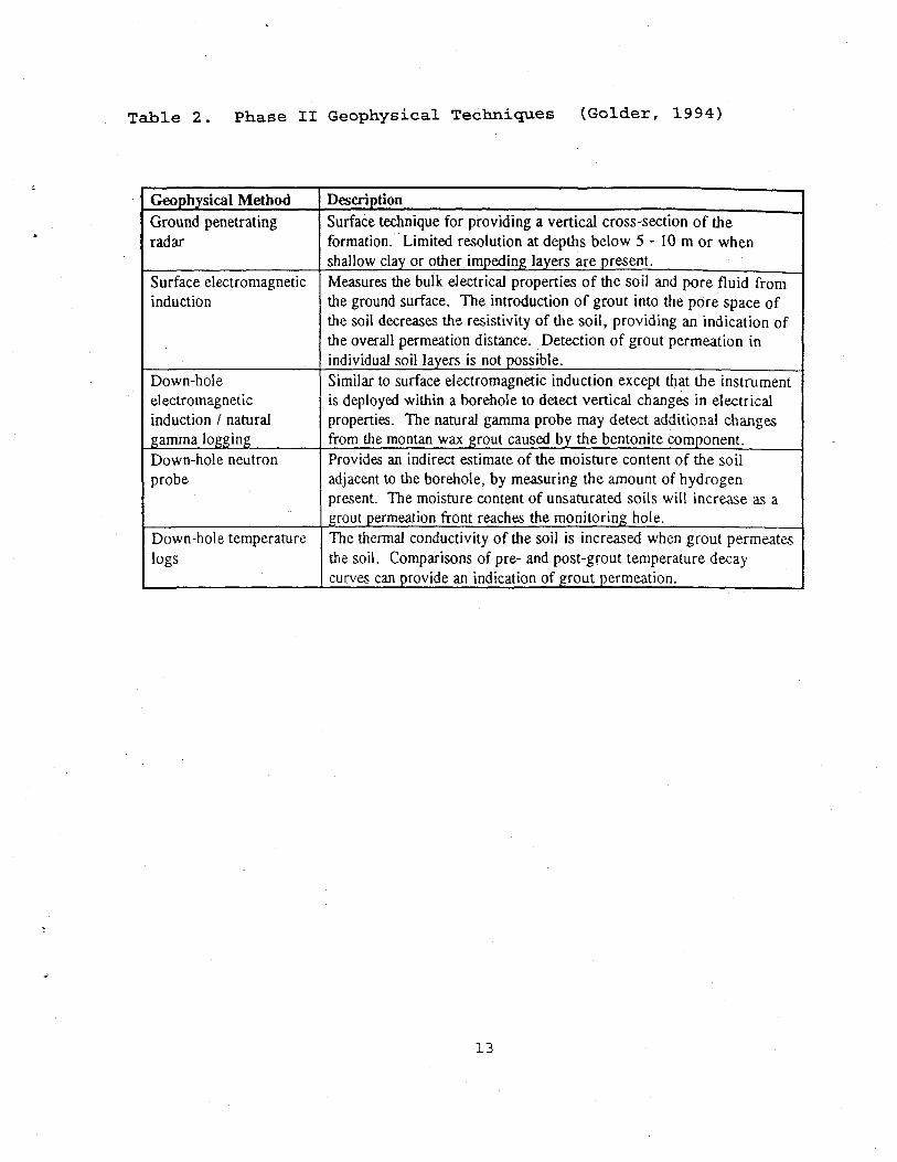
Table 2. Phase II Geophysical Techniques (Golder, 1994)
Geophysical Method Description Ground penetrating radar
Surface technique for providing a vertical cross-section of the formation. Limited resolution at depths below 5 - 10 m or when shallow clay or other impeding layers are present.
Surface electromagnetic induction
Measures the bulk electrical properties of the soil and pore fluid from the ground surface. The introduction of grout into the pore space of the soil decreases the resistivity of the soil, providing an indication of the overall permeation distance. Detection of grout permeation in individual soil layers is not possible.
Down-hole electromagnetic induction / natural gamma logging
Similar to surface electromagnetic induction except that the instrument is deployed within a borehole to detect vertical changes in electrical properties. The natural gamma probe may detect additional changes from the montan wax grout caused by the bentonite component.
Down-hole neutron probe
Provides an indirect estimate of the moisture content of the soil adjacent to the borehole, by measuring the amount of hydrogen present. The moisture content of unsaturated soils will increase as a grout permeation front reaches the monitoring hole.
Down-hole temperature logs
The thermal conductivity of the soil is increased when grout permeates the soil. Comparisons of pre- and post-grout temperature decay curves can provide an indication of grout permeation.
13
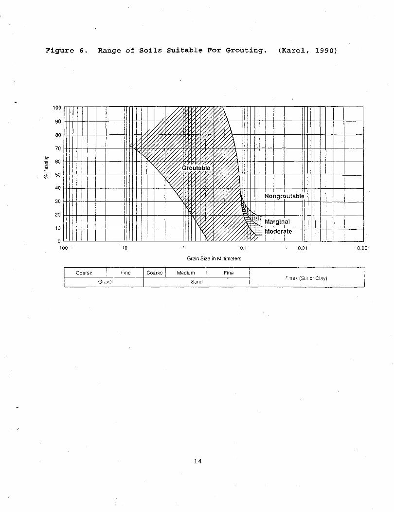
Figure 6. Range of Soils Suitable For Grouting. (Karol, 1990)
100 10 1 0.1
Grain Size in Millimelers
0.01 0.001
Coarse Fine
Gravel
Coarse Medium Fine
Sand Fines (Silt or Clay)
14
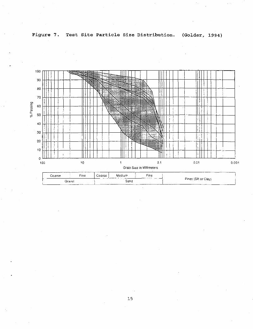
F i g u r e 7 . T e s t S i t e P a r t i c l e S i z e D i s t r i b u t i o n . ( G o l d e r , 1994)
100
90
80
70
•a 60
50
40
30
20
10
X
^ p <» - < i . -<^'~ .. r" ii^LO*' - - ^ r -' \ \
\ - ' • ^ ^ - « s
= * ^ ^ L / I ^ I \
^ » is ** ,<
\ Si , >
\;'f, „ > . *r I , ; ^ \
\ , '^ •*?•* ' " \ \
\ •• ? <• ' , ^ ?v% : > \ : v
N„ ;0 ^
" -
100 10 1 0.1 Grain Size in Millimeters
0.01 0.001
Coarse Fine
Grave! Coarse Medium Fine
Sand Fines (Silt or Clay)
15
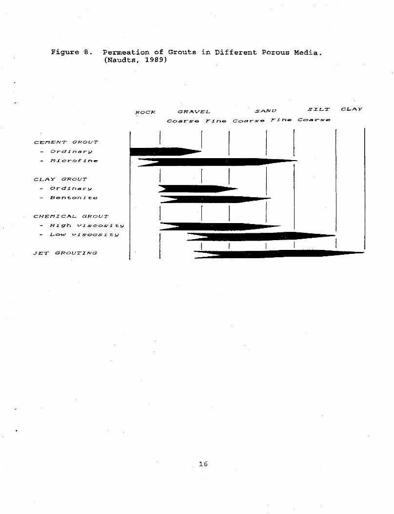
Figure 8. Permeation of Grouts in Different Porous Media. (Naudts, 1989)
SXl^T Cl^fKV
CEnEWT GKOUT
— Orel 1 r» ar y/
— M i c r o / i n e
CL,AY GROUT
— Orel i.rte r <j
— Benson 1 -Ce
CM&ril CAL* GROUT
— L o w v£ s c o ^ 1 fcy
JET GROUTXPJG
16
hydraulic conductivity. Table 3 exemplifies the empirically derived relationship between the two parameters. Soil analyses in the vicinity of the grouting experiment show that the hydraulic conductivity of shallow unconsolidated alluvial formations at SNL range from 10"3 to 10"6 cm/s. Referring to Table 3, the test soil should be groutable with difficulty using low viscosity grouts. Phase I The measured viscosities of the microfine cements (Table 4) injected during Phase I suggest that only the higher hydraulic conductivity soil strata should be groutable with the microfine cement grouts used. Horizontal grout injection was strategically targeted for the 8 to 10 ft. higher permeability cobble zone identified during soil sampling. In an actual subsurface grout barrier emplacement it would be preferable to inject grout in a high permeability layer located between less permeable layers. Theoretical predictions of the grout penetration radius (PR) can be made prior to grout injection using the principles of Darcy's Law. The PR can be estimated assuming two-dimensional radial flow: (Ro/Ri)2ln(Ro/Ri) = (2 (k/u)/pRi2) (Pi-Po) T (1.1) or assuming three-dimensional uniform spherical flow: ( (Ro/Ri)3-l) (1-(Ro/Ri) = (3 (k/u) /pRi2) (Pi-Po) T (1.2) where: Ro = PR (grout radius) [ft.]
Ri = grout sleeve pipe radius [ft.] k = formation permeability [Darcy] u = grout viscosity [centipoise] p = soil matrix porosity [unitless] Pi = injection pressure [psi]
at sleeve pipe Po = pressure at edge of [psi]
PR = 0 T = injection time [min.]
but because of the anisotropic nature of the test site formation and the unpredictable nature of grout set times, accurate calculations of the PR are not practical. Instead the PR should be empirically derived. On large scale grouting projects, grout contractors conduct small scale field testing to determine design parameters and associated costs for the full scale project. Table 5 shows probable estimates of PRs for various soil types.
17
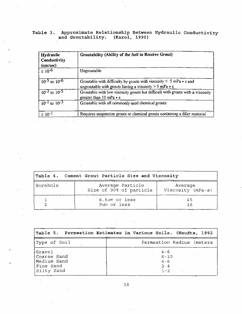
Table 3. Approximate Relationship Between Hydraulic Conductivity and Groutability. (Karol, 1990)
Hydraulic Conductivity (cm/sec)
Groutability (Ability of the Soil to Receive Grout)
< 10"6 Ungroutable
10"5 to 10"6 Groutable with difficulty by grouts with viscosity < 5 mPa • s and ungroutable with grouts having a viscosity > 5 mPa • s
10"3 to 10"5 Groutable with low viscosity grouts but difficult with grouts with a viscosity greater than 10 mPa • s
10' 1 to 10"3 Groutable with all commonly used chemical grouts
> 10" l Requires suspension grouts or chemical grouts containing a filler material
T a b l e 4 . Cemen t G r o u t P a r t i c l e S i z e a n d V i s c o s i t y
B o r e h o l e A v e r a g e P a r t i c l e S i z e of 90% o f p a r t i c l e
A v e r a g e V i s c o s i t y (mPa- s )
1 2
8 .Sum o r l e s s 9um o r l e s s
45 16
T a b l e 5 . P e r m e a t i o n E s t i m a t e s i n V a r i o u s S o i l s . ( N a u d t s , 1 9 9 2
T y p e o f S o i l P e r m e a t i o n R a d i u s ( m e t e r s
G r a v e l C o a r s e S a n d Medium S a n d F i n e S a n d S i l t y S a n d
4 - 6 6 - 1 0 4 - 6 2 - 4 1-2
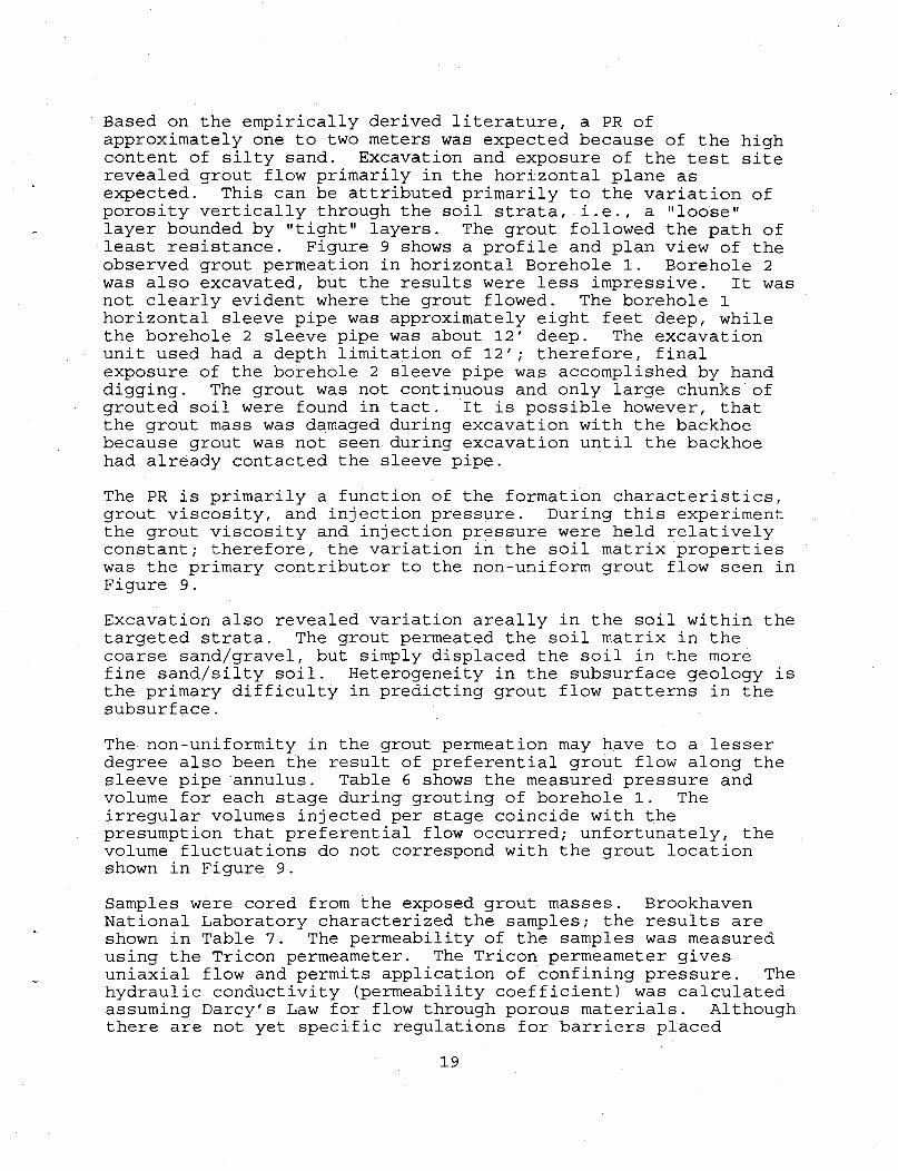
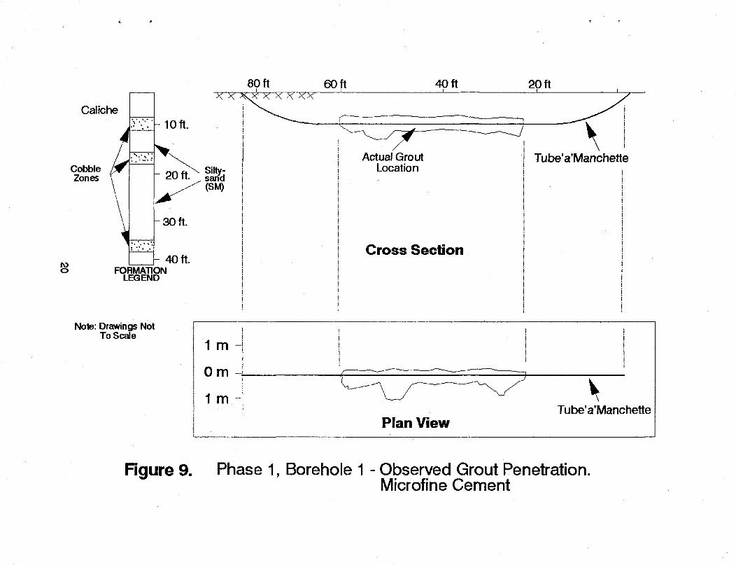
Based on the empirically derived literature, a PR of approximately one to two meters was expected because of the high content of silty sand. Excavation and exposure of the test site revealed grout flow primarily in the horizontal plane as expected. This can be attributed primarily to the variation of porosity vertically through the soil strata, i.e., a "loose" layer bounded by "tight" layers. The grout followed the path of least resistance. Figure 9 shows a profile and plan view of the observed grout permeation in horizontal Borehole 1. Borehole 2 was also excavated, but the results were less impressive. It was not clearly evident where the grout flowed. The borehole 1 horizontal sleeve pipe was approximately eight feet deep, while the borehole 2 sleeve pipe was about 12' deep. The excavation unit used had a depth limitation of 12'; therefore, final exposure of the borehole 2 sleeve pipe was accomplished by hand digging. The grout was not continuous and only large chunks of grouted soil were found in tact. It is possible however, that the grout mass was damaged during excavation with the backhoe because grout was not seen during excavation until the backhoe had already contacted the sleeve pipe.
The PR is primarily a function of the formation characteristics, grout viscosity, and injection pressure. During this experiment the grout viscosity and injection pressure were held relatively constant; therefore, the variation in the soil matrix properties was the primary contributor to the non-uniform grout flow seen in Figure 9. Excavation also revealed variation areally in the soil within the targeted strata. The grout permeated the soil matrix in the coarse sand/gravel, but simply displaced the soil in the more fine sand/silty soil. Heterogeneity in the subsurface geology is the primary difficulty in predicting grout flow patterns in the subsurface. The non-uniformity in the grout permeation may have to a lesser degree also been the result of preferential grout flow along the sleeve pipe annulus. Table 6 shows the measured pressure and volume for each stage during grouting of borehole 1. The irregular volumes injected per stage coincide with the presumption that preferential flow occurred; unfortunately, the volume fluctuations do not correspond with the grout location shown in Figure 9. Samples were cored from the exposed grout masses. Brookhaven National Laboratory characterized the samples; the results are shown in Table 7. The permeability of the samples was measured using the Tricon permeameter. The Tricon permeameter gives uniaxial flow and permits application of confining pressure. The hydraulic conductivity (permeability coefficient) was calculated assuming Darcy's Law for flow through porous materials. Although there are not yet specific regulations for barriers placed
19
IO o
Caliche \ , , < ' ' ' •
Cobble hf Zones \
• ** V« ' *
80 ft 60 ft 40 ft
10ft.
20 ft.
30 ft.
SiHy-sand (SM)
40 ft. FORMATION
LEGEND
Note: Drawings Not To Scale
1 m
Om
1 m
Actual Grout Location
Cross Section
Plan View
20 ft
Tube'a'Manchette
V Tube'a'Manchette
Figure 9. Phase 1, Borehole 1 - Observed Grout Penetration. Microflne Cement
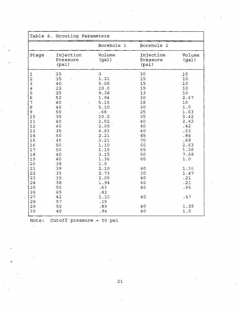
Table 6. Grouting Parameters
Borehole 1 Borehole 2
Stage Injection Volume Injection Volume Pressure (psi)
(gal) Pressure (psi)
(gal)
1 25 3 20 10 2 35 1.21 15 10 3 40 5.05 15 10 4 22 10.0 15 10 5 25 9.36 13 10 6 50 1.94 30 2.47 7 40 5.15 18 10 8 40 5.10 30 1.0 9 50 .68 25 1.63 10 35 10.0 35 3.42 11 40 2.52 40 2.42 12 40 2.05 40 .42 13 35 4.93 40 .63 14 50 2.21 65 .84 15 45 3.21 70 .89 IS 50 1.10 60 2.63 17 50 1.15 65 1.26 18 40 3.15 50 7.68 19 40 1.36 60 1.0 20 38 1.0 21 39 2.10 40 1.36 22 35 2.73 30 1.47 23 35 2.05 40 .21 24 38 1.94 40 .21 25 55 .63 40 .94 26 65 .42 27 42 1.10 60 .47 28 57 .15 29 50 .89 60 1.35 30 40 .94 60 1.0
Note: Cutoff pressure = 50 psi
21
Table 7. Cement Grout Characteristics. Borehole Grout
Material Saturated Hydraulic Conductivity (cm/s)
Compressive Strength (f'c)
(MPa) 1
2
WIPP Microfine Cement BNL
Cement Formulation
5.3 x 1(T8
2.7 x 1CT9
8.4 X 1CT7
28.4 33.6
f'c = 28 day compressive strength in Accordance with ASTM C 39-86
22
beneath existing waste sites, the standard for new installation of waste impoundment liners (4 0 CFR Part 264 Subpart N) will likely apply; and therefore has been used for guidance. This regulation states that a minimum hydraulic conductivity of 1 x 10"7 cm/s is required for all liners. The soil/cement core samples tested (Table 7) met the EPA guidance criteria.
Verification Crosswell seismic tomography, a technology expanding its application beyond the petroleum and mining industry into the environmental arena, was used to map grout beneath the surface during Phase I testing. Crosswell seismic tomography is a nonintrusive geophysical technique that measures anomalies in the subsurface corresponding to changes in the velocity of seismic wave signals. The introduction of a grout material in the soil matrix changes the porosity, fluid content, mineralogy and stiffness of the soil matrix; which consequently creates a seismic velocity change in this region. In this experiment, a seismic survey was conducted before and after grout injection for comparison. The grout invaded soils were visible in crosswell seismic velocity difference tomograms generated from the before and after surveys. Figure 10 exhibits the tomograms for boreholes 1 and 2. The velocity difference tomograms shown in Figure 10 are scaled horizontally and vertically in feet. Note there is some vertical exaggeration (25%). The diagrams exhibit a sliced cross section between the well casings that is perpendicular to the horizontal borehole sleeve pipes. HI and H2 are slices through boreholes 1 and 2 respectively. The west tomogram (BH-7 to BH-2) clearly indicates a velocity difference from the before and after surveys near the center of the tomogram where grout was injected from borehole 1 (HI). The seismic P wave velocity increased by up to 2 0% at the HI location. The exposure and observation of borehole 1 (Figure 9) is consistent with the west tomogram. However, it is interesting to note that portion of the grout mass with dimensions corresponding to Figure 10 was located several feet north of the imaging plane (the two-dimensional slice shown in Figure 10). The east tomogram indicates no anomalous velocity near H2. This is also consistent with the difficulty finding continuous grout during excavation. However, adjacent to BH-2 there apparently was sufficient grout invasion from VI (Figure 2), a vertical hole used to inject excess grout at the end of the experiment. The excess grout was injected at a depth of 13 feet, consequently to deep for excavation. It appears that grout invasion from VI caused a significant seismic anomaly between BH-6 and BH-2 at a depth of 13.5 to 15 feet.
23
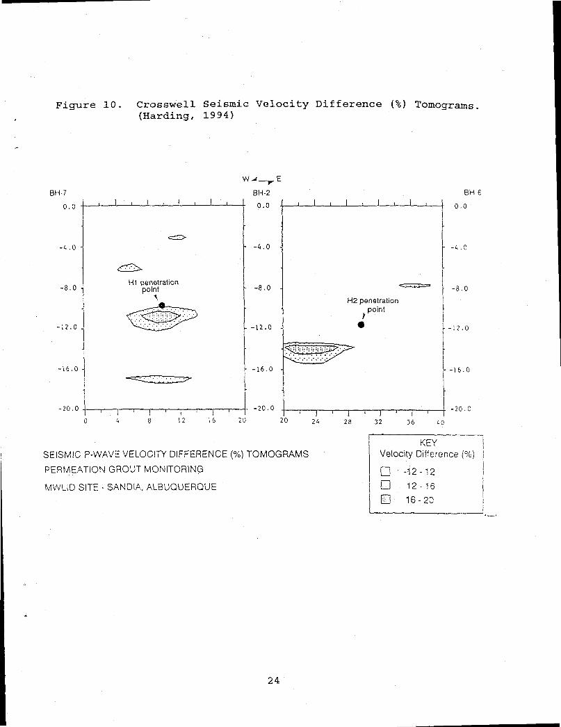
Figure 10. Crosswell Seismic Velocity Difference (%) Tomograms (Harding, 1994)
-20 .0
SEISMIC P-WAVE VELOCITY DIFFERENCE (%) TOMOGRAMS PERMEATION GROUT MONITORING
MWLID SITE - SANDIA, ALBUQUERQUE
H2 penetration point
BH-6
0 . 0
- 4 . 0
- - 8 . 0
-12.0
-16.0
- 2 0 . 0
32 36 t o
KEY Velocity Difference (%)
• -12 -12 m 12 - 16 m 16 -20
24
Since the large grout mass in borehole 1 and the excess grout injected in VI were outside the tomographic imaging plane, it is likely that the anomalies are caused by grouted soil outside the imaging planes. This can occur where the higher velocity of an out-of-plane feature is sufficient to compensate the longer transmission path of out-of-plane rays. Phase II Phase II investigated the penetration and permeability-reduction characteristics of montan-wax and sodium silicate in varying soil conditions. Grout was injected in the vertical tube-a'-manchette sleeve pipe at one foot stages to isolate the permeation characteristics over the range of soil conditions present. A summary report of the Phase II portion of the permeation grouting experiment is entitled Preliminary Results Of Permeation Tests Using Montan Wax and Sodium Silicate Barrier Materials In Unconsolidated Soils At The Mixed Waste Landfill Integrated Demonstration Site (MWLID) (Golder, 1994).
Verification Several geophysical techniques were employed before, during, and after grout injection to target grout zones and map grout intrusion. Preliminary surveys using ground penetrating radar (GPR) indicated the method was of limited value due to interference from the near surface caliche layer; therefore, this method was not used in the study. Electromagnetic induction, and neutron probe logging were used before, during and after grout injection. Both techniques identified soil stratification that coincided with the soil sample borehole logs. Each technique also detected the arrival and location of grout. Borehole temperature logs were run before and after grouting. Measurements were not performed during grouting because of the time required to perform a measurement. The results were reasonably consistent with the other data. Although the geophysical logs showed promise for identifying grout in the subsurface, an actual comparison of the geophysical data and permeability tests on soil samples was not done because the soil samples were disturbed during collection. Because permeability testing on disturbed soil samples is unreliable, a manual inspection of the samples was performed. Both grouts were difficult to identify under manual inspection of soil samples.
25
CONCLUSIONS From the results of the field scale permeation grouting study, the following conclusions can be made: (1) Permeation grouting is a promising method for emplacing
subsurface low permeability barriers in the unconsolidated, semi-arid vadose zone soils common to the Southwest.
(2) One of the primary advantages of permeation grouting using the tube-a'-manchette method is that the injection piping is permanent. After the initial grout injection, subsequent injections can be performed to add more grout or completely different grout materials. This allows for revitalizing degrading barriers or enhancing chemical resistance of the barrier.
(3) Permeation grouting is well suited for relatively homogeneous soil. On the contrary, permeation grouting in heterogenous soil causes preferential flow of grout which is difficult to control and the results are unpredictable.
(4) Permeation grouting is appropriate for emplacing a barrier beneath an existing waste site if a relatively homogeneous, sufficiently high permeability soil layer exists beneath the site.
(5) The microfine cements, montan wax, and sodium silicate grouts tested can be injected into unconsolidated soils having a minimum hydraulic conductivity of 1 x 10"4
using conventional permeation grouting techniques. In lower permeability soils, grout displaces or compacts rather than permeating the soil, which often results in hydraulic fracturing and heaving of the soil.
(6) Microfine cement based grouts produce high strength, durable, low permeability barriers.
(7) Crosswell seismic tomography is effective for identifying cement grout invaded soil. However, at present this technology is not adequate for verifying the continuity of a barrier.
(8) Borehole measurement of electromagnetic resistivity, moisture content, and temperature changes are promising techniques for identifying grout intrusion, but again the current technologies are inadequate for barrier continuity verification.
26
RECOMMENDATIONS FOR FUTURE WORK (1) Grout in multiple boreholes placed close enough
together for the grout to permeate the entire space between and around neighboring boreholes in order to form a continuous grout layer.
(2) Evaluation of barrier integrity by measuring its transmissibility to a flowing fluid across its entire area.
(3) Excavate the barrier and evaluate the joints visually and by coring samples for laboratory testing.
(4) Continue efforts toward barrier integrity verification. This should be included in a separate Technical Task Plan because of the cost and complexity of the task. However, all work in this area should continue to be coordinated with the Subsurface Barrier Emplacement program.
Emerging 3-D seismic tomography imaging appears to have the potential for resolving the correct spatial position of shallow subsurface barriers although the ability of this technique to identify flaws such as a 1 ft 2 hole are questionable due to limitations on the resolution.
(5) Continue to identify and consider test emplacements of emerging grout materials.
27
REFERENCES Allan, M.L., and Kukacka, L.E., 1993. In-Situ Containment and Stabilization of Buried Waste, Annual Report FY 1993, BNL 49709. Golder Associates Inc., 1993. Laboratory Test Results For Evaluating The Performance of Montan Wax and Sodium Silicate Barrier Materials in Unconsolidated Soils.
Golder Associates Inc., 1994. Preliminary Results of Permeation Tests Using Montan Wax and Sodium Silicate Barrier Materials In Unconsolidated Soils At The Mixed Waste Landfill Integrated Demonstration Site (MWLID), Report No. 913-1248.600b,. Harding, R.S., Jr, 1994. Crosswell Seismic Monitoring of a Permeation Grouting Experiment Geo technical Test Range - Sandia National Laboratories, New Mexico, Sandia National Laboratories. Karol, R., 1990. Chemical Grouting, Marcel Dekker, Inc., N.Y. ISBN 0-8247-7888. Naudts, Alex, Brief Overview of the Various Families of Grouts and Their Applications, Trow Consultants, 1989. Voss, Charles F., Caldonazzi, Ortwin, Pertl, Klaus, 1993. Evaluation of a Montan-Wax Emulsion for Constructing Subsurface Barriers, ER'93 Environmental Remediation Conference/ Augusta, GA/ October 24-28, 1993.
28

APPENDIX A
Sample Borehole Logs

PROJECT Mixed Waste Landfill Integrated Demonstration Sandia Nat'l Labs, Albuquerque, NM
JOB NO. E93-1136 DATF 6/30/93
Page 1 of 1
LOG OF TEST BORING NO. 1
r a » B C B
O-WIL
c B O B 3-H 0 - I O*J c a 3 • « U C S.+J --I
-HJ * X *» B-H a c c * » O B B L oatr o Lo
g
Samp
le
B a 3 1-B a E • V)
*JO B on-<E 0 - I E k- • • S B-4 1 3 s a OS) B 0
-i"S i. L. Dry
Dens
ity
lbs. pe
r cu
bic
foot
Mo
istu
re
Cont
ent
Perc
ent
of
Dry
Weig
ht
Unif
ied
Soil
Cl
assi
fi
cati
on
RIG TYPE CME-55 BORING TYPE 6-1/2" Hollow Stem Auger SURFACE ELEV.
r a » B C B
O-WIL
c B O B 3-H 0 - I O*J c a 3 • « U C S.+J --I
-HJ * X *» B-H a c c * » O B B L oatr o Lo
g
Samp
le
B a 3 1-B a E • V)
*JO B on-<E 0 - I E k- • • S B-4 1 3 s a OS) B 0
-i"S i. L. Dry
Dens
ity
lbs. pe
r cu
bic
foot
Mo
istu
re
Cont
ent
Perc
ent
of
Dry
Weig
ht
Unif
ied
Soil
Cl
assi
fi
cati
on
DATUM r a » B C B
O-WIL
c B O B 3-H 0 - I O*J c a 3 • « U C S.+J --I
-HJ * X *» B-H a c c * » O B B L oatr o Lo
g
Samp
le
B a 3 1-B a E • V)
*JO B on-<E 0 - I E k- • • S B-4 1 3 s a OS) B 0
-i"S i. L. Dry
Dens
ity
lbs. pe
r cu
bic
foot
Mo
istu
re
Cont
ent
Perc
ent
of
Dry
Weig
ht
Unif
ied
Soil
Cl
assi
fi
cati
on
r a » B C B
O-WIL
c B O B 3-H 0 - I O*J c a 3 • « U C S.+J --I
-HJ * X *» B-H a c c * » O B B L oatr o Lo
g
Samp
le
B a 3 1-B a E • V)
*JO B on-<E 0 - I E k- • • S B-4 1 3 s a OS) B 0
-i"S i. L. Dry
Dens
ity
lbs. pe
r cu
bic
foot
Mo
istu
re
Cont
ent
Perc
ent
of
Dry
Weig
ht
Unif
ied
Soil
Cl
assi
fi
cati
on
REMARKS VISUAL CLASSIFICATION
0
5
10
15
20
25
30
35
40
45
50
SILTY SAND, very fine, nonplastic, tannish-brown
0
5
10
15
20
25
30
35
40
45
50
( : • > •
S SM SILTY SAND, very fine, nonplastic, tannish-brown
0
5
10
15
20
25
30
35
40
45
50
( : • > •
SILTY SAND, very fine, nonplastic, tannish-brown
0
5
10
15
20
25
30
35
40
45
50
( : • > •
SILTY SAND, very fine, nonplastic, tannish-brown
0
5
10
15
20
25
30
35
40
45
50
, , j : ML SANDY SILT, nonplastic, tannkh-brown
0
5
10
15
20
25
30
35
40
45
50
j t j : SANDY SILT, nonplastic, tannkh-brown
0
5
10
15
20
25
30
35
40
45
50
h S SDLTY SAND, very fine,
occasional small gravel, occasional cobbles, weakly cemented, nonplastic, tannish-brown
0
5
10
15
20
25
30
35
40
45
50
h SDLTY SAND, very fine, occasional small gravel, occasional cobbles, weakly cemented, nonplastic, tannish-brown
0
5
10
15
20
25
30
35
40
45
50
'••.• h SM
SDLTY SAND, very fine, occasional small gravel, occasional cobbles, weakly cemented, nonplastic, tannish-brown
0
5
10
15
20
25
30
35
40
45
50
h SDLTY SAND, very fine, occasional small gravel, occasional cobbles, weakly cemented, nonplastic, tannish-brown
0
5
10
15
20
25
30
35
40
45
50
h SDLTY SAND, very fine, occasional small gravel, occasional cobbles, weakly cemented, nonplastic, tannish-brown
0
5
10
15
20
25
30
35
40
45
50
t • •••"'•••' s 66 ' SILTY SAND, very fine, considerable fine gravel, nonplastic, tannish-brown
0
5
10
15
20
25
30
35
40
45
50
: - « s 44 SILTY SAND, very fine, considerable fine gravel, nonplastic, tannish-brown
0
5
10
15
20
25
30
35
40
45
50
• • . : - « SM
SILTY SAND, very fine, considerable fine gravel, nonplastic, tannish-brown
0
5
10
15
20
25
30
35
40
45
50
: - « s 73
SILTY SAND, very fine, considerable fine gravel, nonplastic, tannish-brown
0
5
10
15
20
25
30
35
40
45
50
1 s 86
SILTY SAND, very fine, considerable fine gravel, nonplastic, tannish-brown
0
5
10
15
20
25
30
35
40
45
50
1
SILTY SAND, very fine, considerable fine gravel, nonplastic, tannish-brown
0
5
10
15
20
25
30
35
40
45
50
". 1 s 88
0
5
10
15
20
25
30
35
40
45
50
*.
' * *
s 65
0
5
10
15
20
25
30
35
40
45
50
' * *
0
5
10
15
20
25
30
35
40
45
50
' * * 5 id
0
5
10
15
20
25
30
35
40
45
50
- . • - . s 52
0
5
10
15
20
25
30
35
40
45
50
- . • - .
0
5
10
15
20
25
30
35
40
45
50
1) 30 SILTY SAND, very fine, occasional fine gravel, nonplastic, tannish-brown
0
5
10
15
20
25
30
35
40
45
50
-; . s 30 SILTY SAND, very fine, occasional fine gravel, nonplastic, tannish-brown
0
5
10
15
20
25
30
35
40
45
50
--. SM
SILTY SAND, very fine, occasional fine gravel, nonplastic, tannish-brown
0
5
10
15
20
25
30
35
40
45
50
6 86
SILTY SAND, very fine, occasional fine gravel, nonplastic, tannish-brown
0
5
10
15
20
25
30
35
40
45
50
- •..'"--. s 50
SILTY SAND, very fine, occasional fine gravel, nonplastic, tannish-brown
0
5
10
15
20
25
30
35
40
45
50
- •..'"--.
SILTY SAND, very fine, occasional fine gravel, nonplastic, tannish-brown
0
5
10
15
20
25
30
35
40
45
50
- •..'"--. i 44
SILTY SAND, very fine, occasional fine gravel, nonplastic, tannish-brown
0
5
10
15
20
25
30
35
40
45
50
Stopped auger @ 27' 6" Stopped sampler @ 29'
0
5
10
15
20
25
30
35
40
45
50
Stopped auger @ 27' 6" Stopped sampler @ 29'
0
5
10
15
20
25
30
35
40
45
50
Stopped auger @ 27' 6" Stopped sampler @ 29'
0
5
10
15
20
25
30
35
40
45
50
Stopped auger @ 27' 6" Stopped sampler @ 29'
0
5
10
15
20
25
30
35
40
45
50
Stopped auger @ 27' 6" Stopped sampler @ 29'
0
5
10
15
20
25
30
35
40
45
50
Stopped auger @ 27' 6" Stopped sampler @ 29'
0
5
10
15
20
25
30
35
40
45
50
Stopped auger @ 27' 6" Stopped sampler @ 29'
0
5
10
15
20
25
30
35
40
45
50
i
Stopped auger @ 27' 6" Stopped sampler @ 29'
0
5
10
15
20
25
30
35
40
45
50
Stopped auger @ 27' 6" Stopped sampler @ 29'
0
5
10
15
20
25
30
35
40
45
50
Stopped auger @ 27' 6" Stopped sampler @ 29'
0
5
10
15
20
25
30
35
40
45
50
Stopped auger @ 27' 6" Stopped sampler @ 29'
0
5
10
15
20
25
30
35
40
45
50
Stopped auger @ 27' 6" Stopped sampler @ 29'
0
5
10
15
20
25
30
35
40
45
50
Stopped auger @ 27' 6" Stopped sampler @ 29'
0
5
10
15
20
25
30
35
40
45
50
Stopped auger @ 27' 6" Stopped sampler @ 29'
0
5
10
15
20
25
30
35
40
45
50
Stopped auger @ 27' 6" Stopped sampler @ 29'
0
5
10
15
20
25
30
35
40
45
50
Stopped auger @ 27' 6" Stopped sampler @ 29'
0
5
10
15
20
25
30
35
40
45
50
Stopped auger @ 27' 6" Stopped sampler @ 29'
0
5
10
15
20
25
30
35
40
45
50
Stopped auger @ 27' 6" Stopped sampler @ 29'
0
5
10
15
20
25
30
35
40
45
50
Stopped auger @ 27' 6" Stopped sampler @ 29'
0
5
10
15
20
25
30
35
40
45
50
Stopped auger @ 27' 6" Stopped sampler @ 29'
0
5
10
15
20
25
30
35
40
45
50
Stopped auger @ 27' 6" Stopped sampler @ 29'
0
5
10
15
20
25
30
35
40
45
50
DEPTH HOUR DATE V None 5
A - Auger Cuttings C - CHE Cont. S - 2" O.D. 1.38" l.D. tube sample. U - 3" O.D. 2.42" l.D. tube sample. T - 3" O.D. thin-walled Shelby tube.
SHB AGRA, Inc. CONSULTING GE0TECHN1CAL ENGINEERS PHOENIX • ALBUQUERQUE • SANTA FE SALT LAKE CITY • EL PASO • TUCSON RENO/SPARKS
PROJECT Mixed Waste Landnil Integrated Demonstration Sandia Nat'l Labs, Albuquerque, NM
Page 1 of 2
LOG OF TEST BORING NO. 2 JOBh in E93-1136 .DATE 7/1/93 JOBh
. .DATE
Dept
h in
Feat
Co
ntin
uous
Pa
natr
atio
n Re
aiat
ance
a u
•H r a B L a . Sa
mple
Sample Type
•UCB a O D - t E 0 M E t- • ! •
B- i 1 3 a a 0 9 1 0 - I t* i. i.
3 *J -U •-I 0 • L 0 C l t -a a Q 0 3 B U O - i 0 Mo
isture
Content
Percent of*
Org
UeiQht
Unified
Sail
da
mnif
ication
RIG TYPE C M E - 5 S
Dept
h in
Feat
Co
ntin
uous
Pa
natr
atio
n Re
aiat
ance
a u
•H r a B L a . Sa
mple
Sample Type
•UCB a O D - t E 0 M E t- • ! •
B- i 1 3 a a 0 9 1 0 - I t* i. i.
3 *J -U •-I 0 • L 0 C l t -a a Q 0 3 B U O - i 0 Mo
isture
Content
Percent of*
Org
UeiQht
Unified
Sail
da
mnif
ication
BORING TYPE 6-1/2" Hollow Stem Auger
Dept
h in
Feat
Co
ntin
uous
Pa
natr
atio
n Re
aiat
ance
a u
•H r a B L a . Sa
mple
Sample Type
•UCB a O D - t E 0 M E t- • ! •
B- i 1 3 a a 0 9 1 0 - I t* i. i.
3 *J -U •-I 0 • L 0 C l t -a a Q 0 3 B U O - i 0 Mo
isture
Content
Percent of*
Org
UeiQht
Unified
Sail
da
mnif
ication SURFACE ELEV.
Dept
h in
Feat
Co
ntin
uous
Pa
natr
atio
n Re
aiat
ance
a u
•H r a B L a . Sa
mple
Sample Type
•UCB a O D - t E 0 M E t- • ! •
B- i 1 3 a a 0 9 1 0 - I t* i. i.
3 *J -U •-I 0 • L 0 C l t -a a Q 0 3 B U O - i 0 Mo
isture
Content
Percent of*
Org
UeiQht
Unified
Sail
da
mnif
ication
DATUM
Dept
h in
Feat
Co
ntin
uous
Pa
natr
atio
n Re
aiat
ance
a u
•H r a B L a . Sa
mple
Sample Type
•UCB a O D - t E 0 M E t- • ! •
B- i 1 3 a a 0 9 1 0 - I t* i. i.
3 *J -U •-I 0 • L 0 C l t -a a Q 0 3 B U O - i 0 Mo
isture
Content
Percent of*
Org
UeiQht
Unified
Sail
da
mnif
ication
R E M A R K S VISUAL CLASSIFICATION
0
5
10
15
20
25
30
35
40
45
50
.- 1 c SM SILTY SAND, very fine, nonplastic, tannish-brown
0
5
10
15
20
25
30
35
40
45
50
.- 1 SILTY SAND, very fine, nonplastic, tannish-brown
0
5
10
15
20
25
30
35
40
45
50
.- 1 SILTY SAND, very fine, nonplastic, tannish-brown
0
5
10
15
20
25
30
35
40
45
50
: : . :
:' * a
SELTY SAND, predominantly fine, occasional small gravel, nonplastic, tannkh-brown
0
5
10
15
20
25
30
35
40
45
50
: : . :
:' * a
SM SELTY SAND, predominantly fine, occasional small gravel, nonplastic, tannkh-brown
0
5
10
15
20
25
30
35
40
45
50
: : . :
:' * a
SELTY SAND, predominantly fine, occasional small gravel, nonplastic, tannkh-brown
0
5
10
15
20
25
30
35
40
45
50
: : . :
:' * a
SELTY SAND, predominantly fine, occasional small gravel, nonplastic, tannkh-brown
0
5
10
15
20
25
30
35
40
45
50
i » • c ML SANDY SILT, nonplastic, brown
0
5
10
15
20
25
30
35
40
45
50
i » SANDY SILT, nonplastic, brown
0
5
10
15
20
25
30
35
40
45
50
: ;. :-
SILTY SAND, predominantly fine, considerable fine gravel, nonplastic, tannish-brown
Note: occasional cobbles @ 8' - 9'
Note: occasional cobbles @ 15' -16'
0
5
10
15
20
25
30
35
40
45
50
: ;. :-
SILTY SAND, predominantly fine, considerable fine gravel, nonplastic, tannish-brown
Note: occasional cobbles @ 8' - 9'
Note: occasional cobbles @ 15' -16'
0
5
10
15
20
25
30
35
40
45
50
: ;. :-
SILTY SAND, predominantly fine, considerable fine gravel, nonplastic, tannish-brown
Note: occasional cobbles @ 8' - 9'
Note: occasional cobbles @ 15' -16'
0
5
10
15
20
25
30
35
40
45
50
: ;. :-
SILTY SAND, predominantly fine, considerable fine gravel, nonplastic, tannish-brown
Note: occasional cobbles @ 8' - 9'
Note: occasional cobbles @ 15' -16'
0
5
10
15
20
25
30
35
40
45
50
: ;. :-
• C
SILTY SAND, predominantly fine, considerable fine gravel, nonplastic, tannish-brown
Note: occasional cobbles @ 8' - 9'
Note: occasional cobbles @ 15' -16'
0
5
10
15
20
25
30
35
40
45
50
: ;. :- I
SILTY SAND, predominantly fine, considerable fine gravel, nonplastic, tannish-brown
Note: occasional cobbles @ 8' - 9'
Note: occasional cobbles @ 15' -16'
0
5
10
15
20
25
30
35
40
45
50
: ;. :- I
SILTY SAND, predominantly fine, considerable fine gravel, nonplastic, tannish-brown
Note: occasional cobbles @ 8' - 9'
Note: occasional cobbles @ 15' -16'
0
5
10
15
20
25
30
35
40
45
50
: ;. :- I SM
SILTY SAND, predominantly fine, considerable fine gravel, nonplastic, tannish-brown
Note: occasional cobbles @ 8' - 9'
Note: occasional cobbles @ 15' -16'
0
5
10
15
20
25
30
35
40
45
50
: ;. :- I
SILTY SAND, predominantly fine, considerable fine gravel, nonplastic, tannish-brown
Note: occasional cobbles @ 8' - 9'
Note: occasional cobbles @ 15' -16'
0
5
10
15
20
25
30
35
40
45
50
: ;. :- I c
SILTY SAND, predominantly fine, considerable fine gravel, nonplastic, tannish-brown
Note: occasional cobbles @ 8' - 9'
Note: occasional cobbles @ 15' -16'
0
5
10
15
20
25
30
35
40
45
50
: ;. :-
SILTY SAND, predominantly fine, considerable fine gravel, nonplastic, tannish-brown
Note: occasional cobbles @ 8' - 9'
Note: occasional cobbles @ 15' -16'
0
5
10
15
20
25
30
35
40
45
50
: ;. :-
SILTY SAND, predominantly fine, considerable fine gravel, nonplastic, tannish-brown
Note: occasional cobbles @ 8' - 9'
Note: occasional cobbles @ 15' -16'
0
5
10
15
20
25
30
35
40
45
50
: ;. :-
1
SILTY SAND, predominantly fine, considerable fine gravel, nonplastic, tannish-brown
Note: occasional cobbles @ 8' - 9'
Note: occasional cobbles @ 15' -16'
0
5
10
15
20
25
30
35
40
45
50
: ;. :-
1 c 107 L.
SILTY SAND, predominantly fine, considerable fine gravel, nonplastic, tannish-brown
Note: occasional cobbles @ 8' - 9'
Note: occasional cobbles @ 15' -16'
0
5
10
15
20
25
30
35
40
45
50
: ;. :-
1
SILTY SAND, predominantly fine, considerable fine gravel, nonplastic, tannish-brown
Note: occasional cobbles @ 8' - 9'
Note: occasional cobbles @ 15' -16'
0
5
10
15
20
25
30
35
40
45
50
: ;. :-
SILTY SAND, predominantly fine, considerable fine gravel, nonplastic, tannish-brown
Note: occasional cobbles @ 8' - 9'
Note: occasional cobbles @ 15' -16'
0
5
10
15
20
25
30
35
40
45
50
: ;. :-
SILTY SAND, predominantly fine, considerable fine gravel, nonplastic, tannish-brown
Note: occasional cobbles @ 8' - 9'
Note: occasional cobbles @ 15' -16'
0
5
10
15
20
25
30
35
40
45
50
: ;. :-
SILTY SAND, predominantly fine, considerable fine gravel, nonplastic, tannish-brown
Note: occasional cobbles @ 8' - 9'
Note: occasional cobbles @ 15' -16'
0
5
10
15
20
25
30
35
40
45
50
: ;. :-
• c
SILTY SAND, predominantly fine, considerable fine gravel, nonplastic, tannish-brown
Note: occasional cobbles @ 8' - 9'
Note: occasional cobbles @ 15' -16'
0
5
10
15
20
25
30
35
40
45
50
: ;. :-
•
SILTY SAND, predominantly fine, considerable fine gravel, nonplastic, tannish-brown
Note: occasional cobbles @ 8' - 9'
Note: occasional cobbles @ 15' -16'
0
5
10
15
20
25
30
35
40
45
50
' • : •
SILTY SAND, very fine, nonplastic, tan
0
5
10
15
20
25
30
35
40
45
50
' • : •
SM SILTY SAND, very fine, nonplastic, tan
0
5
10
15
20
25
30
35
40
45
50
' • : • 1 c 109 1
SILTY SAND, very fine, nonplastic, tan
0
5
10
15
20
25
30
35
40
45
50
' • : • 1 SILTY SAND, very fine, nonplastic, tan
0
5
10
15
20
25
30
35
40
45
50
SM SILTY SAND, very fine, mnderarply re.mentprl white-hrown
0
5
10
15
20
25
30
35
40
45
50
: :r SILTY SAND, very fine, mnderarply re.mentprl white-hrown
0
5
10
15
20
25
30
35
40
45
50
: • .
SILTY SAND, predominantly fine to medium, considerable fine gravel, nonplastic, tannish-brown Note: occasional cobbles from 35'-36'
Note: occasional cobbles @ 46' -49-1/2'
0
5
10
15
20
25
30
35
40
45
50
: • .
c SILTY SAND, predominantly fine to medium, considerable fine gravel, nonplastic, tannish-brown Note: occasional cobbles from 35'-36'
Note: occasional cobbles @ 46' -49-1/2'
0
5
10
15
20
25
30
35
40
45
50
: • .
SILTY SAND, predominantly fine to medium, considerable fine gravel, nonplastic, tannish-brown Note: occasional cobbles from 35'-36'
Note: occasional cobbles @ 46' -49-1/2'
0
5
10
15
20
25
30
35
40
45
50
: • .
SILTY SAND, predominantly fine to medium, considerable fine gravel, nonplastic, tannish-brown Note: occasional cobbles from 35'-36'
Note: occasional cobbles @ 46' -49-1/2'
0
5
10
15
20
25
30
35
40
45
50
: • .
SILTY SAND, predominantly fine to medium, considerable fine gravel, nonplastic, tannish-brown Note: occasional cobbles from 35'-36'
Note: occasional cobbles @ 46' -49-1/2'
0
5
10
15
20
25
30
35
40
45
50
: • .
SILTY SAND, predominantly fine to medium, considerable fine gravel, nonplastic, tannish-brown Note: occasional cobbles from 35'-36'
Note: occasional cobbles @ 46' -49-1/2'
0
5
10
15
20
25
30
35
40
45
50
: • .
SM
SILTY SAND, predominantly fine to medium, considerable fine gravel, nonplastic, tannish-brown Note: occasional cobbles from 35'-36'
Note: occasional cobbles @ 46' -49-1/2'
0
5
10
15
20
25
30
35
40
45
50
: • .
i c 125 0
SILTY SAND, predominantly fine to medium, considerable fine gravel, nonplastic, tannish-brown Note: occasional cobbles from 35'-36'
Note: occasional cobbles @ 46' -49-1/2'
0
5
10
15
20
25
30
35
40
45
50
: • .
i
SILTY SAND, predominantly fine to medium, considerable fine gravel, nonplastic, tannish-brown Note: occasional cobbles from 35'-36'
Note: occasional cobbles @ 46' -49-1/2'
0
5
10
15
20
25
30
35
40
45
50
: • .
SILTY SAND, predominantly fine to medium, considerable fine gravel, nonplastic, tannish-brown Note: occasional cobbles from 35'-36'
Note: occasional cobbles @ 46' -49-1/2'
0
5
10
15
20
25
30
35
40
45
50
: • .
SILTY SAND, predominantly fine to medium, considerable fine gravel, nonplastic, tannish-brown Note: occasional cobbles from 35'-36'
Note: occasional cobbles @ 46' -49-1/2'
0
5
10
15
20
25
30
35
40
45
50
: • .
SILTY SAND, predominantly fine to medium, considerable fine gravel, nonplastic, tannish-brown Note: occasional cobbles from 35'-36'
Note: occasional cobbles @ 46' -49-1/2'
0
5
10
15
20
25
30
35
40
45
50
: • .
c 94 1
SILTY SAND, predominantly fine to medium, considerable fine gravel, nonplastic, tannish-brown Note: occasional cobbles from 35'-36'
Note: occasional cobbles @ 46' -49-1/2'
0
5
10
15
20
25
30
35
40
45
50
: • .
98 2
SILTY SAND, predominantly fine to medium, considerable fine gravel, nonplastic, tannish-brown Note: occasional cobbles from 35'-36'
Note: occasional cobbles @ 46' -49-1/2'
0
5
10
15
20
25
30
35
40
45
50
: • .
SILTY SAND, predominantly fine to medium, considerable fine gravel, nonplastic, tannish-brown Note: occasional cobbles from 35'-36'
Note: occasional cobbles @ 46' -49-1/2'
0
5
10
15
20
25
30
35
40
45
50
0
5
10
15
20
25
30
35
40
45
50 CROU NDUATER SAMP LE TYPE !
DEPTH HOUR DATE V None 5
2" O.D. 1.38" I.D. tube sample. 3" O.D. 2.42" I.D. tube sample. 3" O.D. thin-walled Shelby tube.
SHB AGRA, Inc. CONSULTING GEOTECHNICAL ENGINEERS PHOENIX • ALBUQUERQUE • SANTA FE SALT LAKE CITY • EL PASO • TUCSON RENO/SPARtCS
PROJECT Mixed Waste Landfill Integrated Demonstration Sandia Nat'l Labs, Albuquerque, NM
JOB NO. E93-1136 DATE 7/1/931
Page 2 of 2
LOG OF TEST BORING NO. 2
c 1 0 1 3-H U 0+J C 3 « « C S-*J - U J • .p «•-< e c u o v a O I L E -
a u •-< r a c a L 0 O -J
: i. o n n E 0 - I E
IK • * *
3 • a. OS * 0 ffl .) WB
3 *J JJ •H 0 It L 0 C B i ll a a u 3UXI J-XI a O-i u
<t-4J or u a S.+J+J-H Deem 4-1 ai 0 3 H4-I 0
•H C i- 3 0 0 IB S. EUCLO
I --( d-•-1 C U o
•H-H U4J C O H S 3MCJ U
RIG TYPE CME-55 BORING TYPE 6-1/2" Hollow Stem Auger SURFACE ELEV.
DATUM
REMARKS UISUAL CLASSIF ICAT ION
50
55
60
65
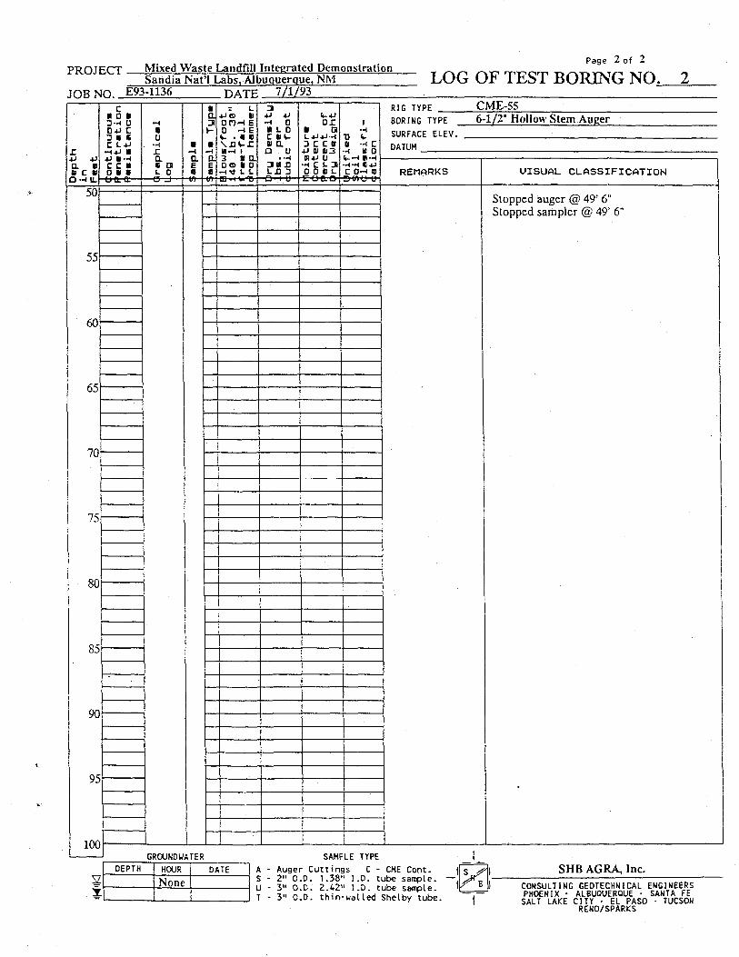
Stopped auger @ 49' 6" Stopped sampler @ 49' 6"
70
75
80
85
90
95
100 GROUNDWATER
DEPTH HOUR DATE V None 5
SAMPLE TYPE A - Auger Cuttings C - CME Cont. S - 2" O.D. 1.38" I.D. tube sample. U - 3" O.D. 2.42" I.D. tube sampte. T - 3" O.D. thin-walled Shelby tube.
SHB AGRA, Inc. CONSULTING GE0TECHNICAL ENGINEERS PHOENIX • ALBUQUERQUE • SANTA FE SALT LAKE CITY - EL PASO • TUCSON RENO/SPARKS
PROJECT Mixed Waste Landfill Integrated Demonstration Sandia Nat'l Labs, Albuquerque, NM
JOB NO. E93-1136 HATF 7/2/93
Page 1 of 1
LOG OF TEST BORING NO. Depth
in
Feet
c I D ) D«< U 0+1 C 3 « • C t + J
•H4J • 4J •• -< c c a o a a OCLO:
-H
Sample
Sample T
ype
4-1 (S 01 onn e 0 - I E i- ' I f B - l 1 3 « a Oo 01 0 tawit-n Dr
y Density
lbs. p
er
cubic
root
Moisture
Content
Percent
or
Dry Weight
Unified
Soil
Classifi
cation
RIG TYPE CME-S5 BORING TYPE 6-1/2" Hollow Stem Auger
Depth
in
Feet
c I D ) D«< U 0+1 C 3 « • C t + J
•H4J • 4J •• -< c c a o a a OCLO: Gr
aphics
Log
Sample
Sample T
ype
4-1 (S 01 onn e 0 - I E i- ' I f B - l 1 3 « a Oo 01 0 tawit-n Dr
y Density
lbs. p
er
cubic
root
Moisture
Content
Percent
or
Dry Weight
Unified
Soil
Classifi
cation SURFACE ELEV.
Depth
in
Feet
c I D ) D«< U 0+1 C 3 « • C t + J
•H4J • 4J •• -< c c a o a a OCLO: Gr
aphics
Log
Sample
Sample T
ype
4-1 (S 01 onn e 0 - I E i- ' I f B - l 1 3 « a Oo 01 0 tawit-n Dr
y Density
lbs. p
er
cubic
root
Moisture
Content
Percent
or
Dry Weight
Unified
Soil
Classifi
cation
DATUM
Depth
in
Feet
c I D ) D«< U 0+1 C 3 « • C t + J
•H4J • 4J •• -< c c a o a a OCLO: Gr
aphics
Log
Sample
Sample T
ype
4-1 (S 01 onn e 0 - I E i- ' I f B - l 1 3 « a Oo 01 0 tawit-n Dr
y Density
lbs. p
er
cubic
root
Moisture
Content
Percent
or
Dry Weight
Unified
Soil
Classifi
cation
REMARKS UISUAL CLASSIFICATION
0
5
10
15
20
25
30
35
40
45
50
SELTY SAND, very fine, nonplaslic, tannish-brown
0
5
10
15
20
25
30
35
40
45
50
. • - H'~ SM SELTY SAND, very fine, nonplaslic, tannish-brown
0
5
10
15
20
25
30
35
40
45
50
. • - 1 SELTY SAND, very fine, nonplaslic, tannish-brown
0
5
10
15
20
25
30
35
40
45
50
. • - 1 SELTY SAND, very fine, nonplaslic, tannish-brown
0
5
10
15
20
25
30
35
40
45
50
i i
»
SANDY SILT, nonplastic, tannish-brown
0
5
10
15
20
25
30
35
40
45
50
i i
» ML SANDY SILT, nonplastic, tannish-brown
0
5
10
15
20
25
30
35
40
45
50
i i
» : • SANDY SILT, nonplastic, tannish-brown
0
5
10
15
20
25
30
35
40
45
50
• • : • C
\
SILTY SAND, very fine, occasional small gravel, occasional cobbles, weakly cemented, nonplastic, tannish-brown
Note: cobbles @ 8' - 9-1/2'
0
5
10
15
20
25
30
35
40
45
50
m SM
\
SILTY SAND, very fine, occasional small gravel, occasional cobbles, weakly cemented, nonplastic, tannish-brown
Note: cobbles @ 8' - 9-1/2'
0
5
10
15
20
25
30
35
40
45
50
\
SILTY SAND, very fine, occasional small gravel, occasional cobbles, weakly cemented, nonplastic, tannish-brown
Note: cobbles @ 8' - 9-1/2'
0
5
10
15
20
25
30
35
40
45
50
\
SILTY SAND, very fine, occasional small gravel, occasional cobbles, weakly cemented, nonplastic, tannish-brown
Note: cobbles @ 8' - 9-1/2'
0
5
10
15
20
25
30
35
40
45
50
\
SILTY SAND, very fine, occasional small gravel, occasional cobbles, weakly cemented, nonplastic, tannish-brown
Note: cobbles @ 8' - 9-1/2'
0
5
10
15
20
25
30
35
40
45
50
; : : • • •
\
SILTY SAND, very fine, occasional small gravel, occasional cobbles, weakly cemented, nonplastic, tannish-brown
Note: cobbles @ 8' - 9-1/2'
0
5
10
15
20
25
30
35
40
45
50
; : : m c \
SILTY SAND, very fine, occasional small gravel, occasional cobbles, weakly cemented, nonplastic, tannish-brown
Note: cobbles @ 8' - 9-1/2'
0
5
10
15
20
25
30
35
40
45
50
; : :
SILTY SAND, very fine, considerable fine gravel, nonplastic, tannish-brown
0
5
10
15
20
25
30
35
40
45
50
; : :
SILTY SAND, very fine, considerable fine gravel, nonplastic, tannish-brown
0
5
10
15
20
25
30
35
40
45
50
; : :
.". SM
SILTY SAND, very fine, considerable fine gravel, nonplastic, tannish-brown
0
5
10
15
20
25
30
35
40
45
50
; : :
£ c
SILTY SAND, very fine, considerable fine gravel, nonplastic, tannish-brown
0
5
10
15
20
25
30
35
40
45
50
; : :
£ SILTY SAND, very fine, considerable fine gravel, nonplastic, tannish-brown
0
5
10
15
20
25
30
35
40
45
50
; : :
SILTY SAND, very fine, considerable fine gravel, nonplastic, tannish-brown
0
5
10
15
20
25
30
35
40
45
50
; : :
SILTY SAND, very fine, considerable fine gravel, nonplastic, tannish-brown
0
5
10
15
20
25
30
35
40
45
50
; : :
• • '
SILTY SAND, very fine, considerable fine gravel, nonplastic, tannish-brown
0
5
10
15
20
25
30
35
40
45
50
; : :
• • '
c
SILTY SAND, very fine, considerable fine gravel, nonplastic, tannish-brown
0
5
10
15
20
25
30
35
40
45
50
::~-SILTY SAND, very fine, occasional fine gravel, nonplastic, tannish-brown
0
5
10
15
20
25
30
35
40
45
50
::~- • r SILTY SAND, very fine, occasional fine gravel, nonplastic, tannish-brown
0
5
10
15
20
25
30
35
40
45
50
::~-SILTY SAND, very fine, occasional fine gravel, nonplastic, tannish-brown
0
5
10
15
20
25
30
35
40
45
50
::~-
_£ SM
SILTY SAND, very fine, occasional fine gravel, nonplastic, tannish-brown
0
5
10
15
20
25
30
35
40
45
50
::~-
'.' H
SILTY SAND, very fine, occasional fine gravel, nonplastic, tannish-brown
0
5
10
15
20
25
30
35
40
45
50
::~-
'.' H I
0
5
10
15
20
25
30
35
40
45
50
0
5
10
15
20
25
30
35
40
45
50
Stopped auger @ 28' Stopped sampler @ 28'
0
5
10
15
20
25
30
35
40
45
50
Stopped auger @ 28' Stopped sampler @ 28'
0
5
10
15
20
25
30
35
40
45
50
Stopped auger @ 28' Stopped sampler @ 28'
0
5
10
15
20
25
30
35
40
45
50
Stopped auger @ 28' Stopped sampler @ 28'
0
5
10
15
20
25
30
35
40
45
50
Stopped auger @ 28' Stopped sampler @ 28'
0
5
10
15
20
25
30
35
40
45
50
1
Stopped auger @ 28' Stopped sampler @ 28'
0
5
10
15
20
25
30
35
40
45
50
i
Stopped auger @ 28' Stopped sampler @ 28'
0
5
10
15
20
25
30
35
40
45
50
Stopped auger @ 28' Stopped sampler @ 28'
0
5
10
15
20
25
30
35
40
45
50
Stopped auger @ 28' Stopped sampler @ 28'
0
5
10
15
20
25
30
35
40
45
50
Stopped auger @ 28' Stopped sampler @ 28'
0
5
10
15
20
25
30
35
40
45
50
Stopped auger @ 28' Stopped sampler @ 28'
0
5
10
15
20
25
30
35
40
45
50
Stopped auger @ 28' Stopped sampler @ 28'
0
5
10
15
20
25
30
35
40
45
50
Stopped auger @ 28' Stopped sampler @ 28'
0
5
10
15
20
25
30
35
40
45
50
Stopped auger @ 28' Stopped sampler @ 28'
0
5
10
15
20
25
30
35
40
45
50
Stopped auger @ 28' Stopped sampler @ 28'
0
5
10
15
20
25
30
35
40
45
50
Stopped auger @ 28' Stopped sampler @ 28'
0
5
10
15
20
25
30
35
40
45
50
Stopped auger @ 28' Stopped sampler @ 28'
0
5
10
15
20
25
30
35
40
45
50
Stopped auger @ 28' Stopped sampler @ 28'
0
5
10
15
20
25
30
35
40
45
50
Stopped auger @ 28' Stopped sampler @ 28'
0
5
10
15
20
25
30
35
40
45
50
Stopped auger @ 28' Stopped sampler @ 28'
0
5
10
15
20
25
30
35
40
45
50 1
Stopped auger @ 28' Stopped sampler @ 28'
0
5
10
15
20
25
30
35
40
45
50 GR0< JNDU H.TER SAMP LE TYPE 1
DEPTH HOUR DATE y None %
A - Auger Cuttings C - CME Cont. S - 2" 0.0. 1.38" I.D. tube sample. — U - 3" O.D. 2.42" I.D. tube sample. T - 3" O.D. thin-walled Shelby tube.
SHB AGRA, Inc. CONSULTING GEOTECHN1CAL ENGINEERS PHOENIX • ALBUQUERQUE - SANTA FE SALT LAKE CITY • EL PASO • TUCSON RENO/SPARKS
PROJECT Mixed Waste Landfill Integrated Demonstration Sandia Nat'l Labs, Albuquerque, NM
JOB NO. E93-1136 DATK 7/2/93
Page 1 of 1
LOG OF TEST BORING NO. 4
r a MCI
O-* U.
c I D I D-H 0 0*J C 3 • « C L+J
• -HJ M C C I O i l oo.tr
a u £ a • a i- o a _j
5 S. 4J<S> tj OfJH E 0 H E v • e « \ j n - x 3 u a 0(9 B 0
- I i f J. S. tD-riWTS
3 4J +J •H D H O C « i -in a o u
• •H 3(113
*-4J 0 £
tu a 1.4J+J-H K C I 4J SI «I3 HH-t u H C L J 0 0 (II L E O 0 . O
1 --<
TJ *-I -HC
•-( HO %--( «-H •H-H «JJ C O - f l rxno u
RIG TYPE CME-55 BORING TYPE 6-1/2" Hollow Stem Auger SURFACE ELEV. DATUM
REMARKS U I S U A L C L A S S I F I C A T I O N
10
15
20
25
30
35
40
45
50
i SM SILTY SAND, very fine, nonplastic, tannish-brown
ML
SANDY SILT, occasional fine gravel, nonplastic, tannish-brown
Note: occasional cobbles from 8' -8-1/2'
SILTY SAND, predominantly fine, considerable fine gravel, nonplastic, tannish-brown
JUL
SM _C
SILTY SAND, very fine, occasional small gravel, nonplastic, tannish-brown
Stopped auger @ 27' Stopped sampler @ 27'
GROUNDWATER DEPTH HOUR DATE
V None z
SAMPLE TYPE A - Auger Cuttings C - CME Cont. S - 2" O.D. 1.38" l.D. tube sample. U - 3" O.D. 2.42" l.D. tube sample. T - 3" O.D. thin-walled Shelby tube.
SHB AGRA, Inc. CONSULTING GEOTECHNICAL ENGINEERS PHOENIX • ALBUQUERQUE - SANTA FE SALT LAKE CITY • EL PASO • TUCSON RENO/SPARKS
PROJECT Mixed Waste Landfill Integrated Demonstration Sandia Nat'l Labs, Albuquerque, NM
Page 1 of 1
LOG OF TEST BORING NO, 5 TOR NO E93-1136 .DATE 7/6/93
Dept
h in
Feat
c • 0 • D-H 0 0+J C 3 « •
~i+i a +» B-H c : i 0 B B uacc Qr
aphi
cal
Log
Samp
ia
Samp
le T
ype : S.
+JS> II D O - I E 0 -1 E fc- • • « a - t i 3 B a 0<9 B 0
Dry
Dens
ity
Iba. per
cu
bic
foot
Mo
istu
re
Cont
ent
Perc
ent of
Dr
y We
ight
Un
ifie
d So
il
Clss
sifi
-ce
tion
RIG TYPE CME-55
Dept
h in
Feat
c • 0 • D-H 0 0+J C 3 « •
~i+i a +» B-H c : i 0 B B uacc Qr
aphi
cal
Log
Samp
ia
Samp
le T
ype : S.
+JS> II D O - I E 0 -1 E fc- • • « a - t i 3 B a 0<9 B 0
Dry
Dens
ity
Iba. per
cu
bic
foot
Mo
istu
re
Cont
ent
Perc
ent of
Dr
y We
ight
Un
ifie
d So
il
Clss
sifi
-ce
tion
BORING TYPE 6-1/2" Hollow Stem Auger
Dept
h in
Feat
c • 0 • D-H 0 0+J C 3 « •
~i+i a +» B-H c : i 0 B B uacc Qr
aphi
cal
Log
Samp
ia
Samp
le T
ype : S.
+JS> II D O - I E 0 -1 E fc- • • « a - t i 3 B a 0<9 B 0
Dry
Dens
ity
Iba. per
cu
bic
foot
Mo
istu
re
Cont
ent
Perc
ent of
Dr
y We
ight
Un
ifie
d So
il
Clss
sifi
-ce
tion
SURFACE ELEV.
Dept
h in
Feat
c • 0 • D-H 0 0+J C 3 « •
~i+i a +» B-H c : i 0 B B uacc Qr
aphi
cal
Log
Samp
ia
Samp
le T
ype : S.
+JS> II D O - I E 0 -1 E fc- • • « a - t i 3 B a 0<9 B 0
Dry
Dens
ity
Iba. per
cu
bic
foot
Mo
istu
re
Cont
ent
Perc
ent of
Dr
y We
ight
Un
ifie
d So
il
Clss
sifi
-ce
tion
DATUM
Dept
h in
Feat
c • 0 • D-H 0 0+J C 3 « •
~i+i a +» B-H c : i 0 B B uacc Qr
aphi
cal
Log
Samp
ia
Samp
le T
ype : S.
+JS> II D O - I E 0 -1 E fc- • • « a - t i 3 B a 0<9 B 0
Dry
Dens
ity
Iba. per
cu
bic
foot
Mo
istu
re
Cont
ent
Perc
ent of
Dr
y We
ight
Un
ifie
d So
il
Clss
sifi
-ce
tion
Dept
h in
Feat
c • 0 • D-H 0 0+J C 3 « •
~i+i a +» B-H c : i 0 B B uacc Qr
aphi
cal
Log
Samp
ia
Samp
le T
ype : S.
+JS> II D O - I E 0 -1 E fc- • • « a - t i 3 B a 0<9 B 0
Dry
Dens
ity
Iba. per
cu
bic
foot
Mo
istu
re
Cont
ent
Perc
ent of
Dr
y We
ight
Un
ifie
d So
il
Clss
sifi
-ce
tion
REMARKS U I S U A L C L A S S I F I C A T I O N
0
5
10
15
20
25
30
35
40
45
50
SELTY SAND, very fine, nonplastic, tannish-brown
0
5
10
15
20
25
30
35
40
45
50
i c SM SELTY SAND, very fine, nonplastic, tannish-brown
0
5
10
15
20
25
30
35
40
45
50
i SELTY SAND, very fine, nonplastic, tannish-brown
0
5
10
15
20
25
30
35
40
45
50
i SELTY SAND, very fine, nonplastic, tannish-brown
0
5
10
15
20
25
30
35
40
45
50
i i
t i i i i i i I t i
r i i • i ! 1 1 1
SANDY SILT, occasional small gravel, tannish-brown
Note: occasional cobbles from 8' -9'
0
5
10
15
20
25
30
35
40
45
50
i i
t i i i i i i I t i
r i i • i ! 1 1 1
SANDY SILT, occasional small gravel, tannish-brown
Note: occasional cobbles from 8' -9'
0
5
10
15
20
25
30
35
40
45
50
i i
t i i i i i i I t i
r i i • i ! 1 1 1
1 SANDY SILT, occasional small gravel, tannish-brown
Note: occasional cobbles from 8' -9'
0
5
10
15
20
25
30
35
40
45
50
i i
t i i i i i i I t i
r i i • i ! 1 1 1
1 c Ml.
SANDY SILT, occasional small gravel, tannish-brown
Note: occasional cobbles from 8' -9'
0
5
10
15
20
25
30
35
40
45
50
i i
t i i i i i i I t i
r i i • i ! 1 1 1
1 SANDY SILT, occasional small gravel, tannish-brown
Note: occasional cobbles from 8' -9'
0
5
10
15
20
25
30
35
40
45
50
i i
t i i i i i i I t i
r i i • i ! 1 1 1
SANDY SILT, occasional small gravel, tannish-brown
Note: occasional cobbles from 8' -9'
0
5
10
15
20
25
30
35
40
45
50
i i
t i i i i i i I t i
r i i • i ! 1 1 1
SANDY SILT, occasional small gravel, tannish-brown
Note: occasional cobbles from 8' -9'
0
5
10
15
20
25
30
35
40
45
50
i i
t i i i i i i I t i
r i i • i ! 1 1 1 i__J
SANDY SILT, occasional small gravel, tannish-brown
Note: occasional cobbles from 8' -9'
0
5
10
15
20
25
30
35
40
45
50
; ; : ;
I c SILTY SAND, predominantly fine to medium, considerable fine gravel, occasional cobbles, nonplastic, tannish-brown
0
5
10
15
20
25
30
35
40
45
50
; ; : ;
I SILTY SAND, predominantly fine to medium, considerable fine gravel, occasional cobbles, nonplastic, tannish-brown
0
5
10
15
20
25
30
35
40
45
50
; ; : ;
I SM
SILTY SAND, predominantly fine to medium, considerable fine gravel, occasional cobbles, nonplastic, tannish-brown
0
5
10
15
20
25
30
35
40
45
50
; ; : ;
SILTY SAND, predominantly fine to medium, considerable fine gravel, occasional cobbles, nonplastic, tannish-brown
0
5
10
15
20
25
30
35
40
45
50
; ; : ;
SILTY SAND, predominantly fine to medium, considerable fine gravel, occasional cobbles, nonplastic, tannish-brown
0
5
10
15
20
25
30
35
40
45
50
; ; : ;
SILTY SAND, predominantly fine to medium, considerable fine gravel, occasional cobbles, nonplastic, tannish-brown
0
5
10
15
20
25
30
35
40
45
50
; ; : ;
SILTY SAND, predominantly fine to medium, considerable fine gravel, occasional cobbles, nonplastic, tannish-brown
0
5
10
15
20
25
30
35
40
45
50
; ; : ;
SILTY SAND, predominantly fine to medium, considerable fine gravel, occasional cobbles, nonplastic, tannish-brown
0
5
10
15
20
25
30
35
40
45
50
; ; : ;
H -e
SILTY SAND, predominantly fine to medium, considerable fine gravel, occasional cobbles, nonplastic, tannish-brown
0
5
10
15
20
25
30
35
40
45
50
; ; : ;
H -e !
SILTY SAND, predominantly fine to medium, considerable fine gravel, occasional cobbles, nonplastic, tannish-brown
0
5
10
15
20
25
30
35
40
45
50
• B B
SILTY SAND, predominantly fine, considerable fine gravel, nonplastic, tannish-brown
0
5
10
15
20
25
30
35
40
45
50
• B B
SILTY SAND, predominantly fine, considerable fine gravel, nonplastic, tannish-brown
0
5
10
15
20
25
30
35
40
45
50
• B B SM
SILTY SAND, predominantly fine, considerable fine gravel, nonplastic, tannish-brown
0
5
10
15
20
25
30
35
40
45
50
E c
SILTY SAND, predominantly fine, considerable fine gravel, nonplastic, tannish-brown
0
5
10
15
20
25
30
35
40
45
50
E SILTY SAND, predominantly fine, considerable fine gravel, nonplastic, tannish-brown
0
5
10
15
20
25
30
35
40
45
50
Stopped auger @ 28' Stopped sampler @ 28'
0
5
10
15
20
25
30
35
40
45
50
Stopped auger @ 28' Stopped sampler @ 28'
0
5
10
15
20
25
30
35
40
45
50
Stopped auger @ 28' Stopped sampler @ 28'
0
5
10
15
20
25
30
35
40
45
50
Stopped auger @ 28' Stopped sampler @ 28'
0
5
10
15
20
25
30
35
40
45
50
Stopped auger @ 28' Stopped sampler @ 28'
0
5
10
15
20
25
30
35
40
45
50
Stopped auger @ 28' Stopped sampler @ 28'
0
5
10
15
20
25
30
35
40
45
50
Stopped auger @ 28' Stopped sampler @ 28'
0
5
10
15
20
25
30
35
40
45
50
Stopped auger @ 28' Stopped sampler @ 28'
0
5
10
15
20
25
30
35
40
45
50
Stopped auger @ 28' Stopped sampler @ 28'
0
5
10
15
20
25
30
35
40
45
50
Stopped auger @ 28' Stopped sampler @ 28'
0
5
10
15
20
25
30
35
40
45
50
Stopped auger @ 28' Stopped sampler @ 28'
0
5
10
15
20
25
30
35
40
45
50
Stopped auger @ 28' Stopped sampler @ 28'
0
5
10
15
20
25
30
35
40
45
50
Stopped auger @ 28' Stopped sampler @ 28'
0
5
10
15
20
25
30
35
40
45
50
Stopped auger @ 28' Stopped sampler @ 28'
0
5
10
15
20
25
30
35
40
45
50
Stopped auger @ 28' Stopped sampler @ 28'
0
5
10
15
20
25
30
35
40
45
50
Stopped auger @ 28' Stopped sampler @ 28'
0
5
10
15
20
25
30
35
40
45
50
Stopped auger @ 28' Stopped sampler @ 28'
0
5
10
15
20
25
30
35
40
45
50
Stopped auger @ 28' Stopped sampler @ 28'
0
5
10
15
20
25
30
35
40
45
50
Stopped auger @ 28' Stopped sampler @ 28'
0
5
10
15
20
25
30
35
40
45
50
0
5
10
15
20
25
30
35
40
45
50 1
0
5
10
15
20
25
30
35
40
45
50 1
0
5
10
15
20
25
30
35
40
45
50 GROU NDUATER SAMP LE TYPE 1
DEPTH HOUR DATE y None 5
2" O.D. 1.38" I.D. tube sample. 3" O.D. 2.42" I.D. tube sample. 3" O.D. thin-walled Shelby tube.
SHB AGRA, Inc. CONSULTING GEOTECHNICAL ENGINEERS PHOENIX • ALBUQUERQUE - SANTA FE SALT LAKE CITY • EL PASO • TUCSON
RENO/SPARKS
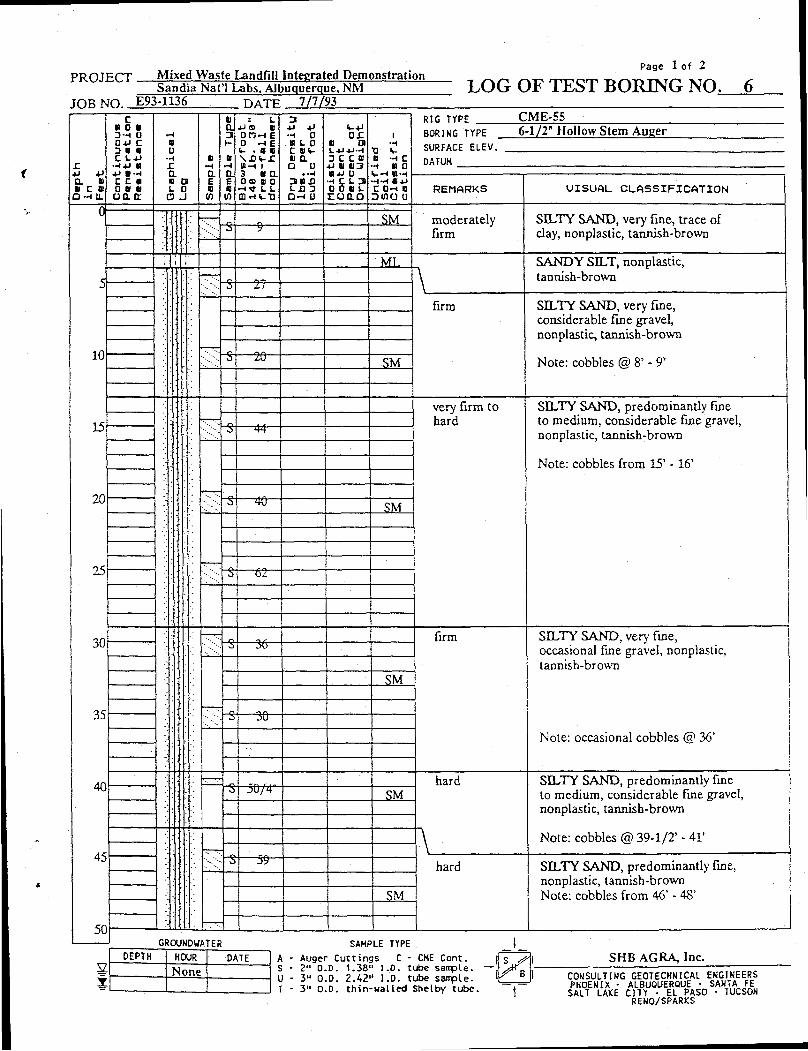
PROJECT Mixed Waste Landfill Integrated Demonstration Sandia Nat'l Labs. Albuquerque. NM
Page 1 of 2
LOG OF TEST BORING NO. 6 TOR MO E93-1136 HATF 7/7/ 93 TOR MO E93-1136 HATF
X 0. U « C B
Q--IU. Cont
inuo
us
Pene
trat
ion
Resi
stan
ce
Grap
hica
l
- ,
Samp
le
Samp
le T
ype : 1.
4JO tl D 5 H E 0 - I E V . « B
Vt-i 1 3 * CL 0 9 I D CO.-H.TJ Dr
y De
nsit
y lbs. p
er
cubi
c foot
OX III a 3 C C 0
4J (1 0 1 3 W-U 0
H C i . 3 0 0 III J.
r o n . 0 Unif
ied
Soil
Ci
assi
fi-
cati
on
RIG TYPE CME-55 BORING TYPE 6-1/2" Hollow Stem Auger SURFACE ELEV.
X 0. U « C B
Q--IU. Cont
inuo
us
Pene
trat
ion
Resi
stan
ce
Grap
hica
l
- ,
Samp
le
Samp
le T
ype : 1.
4JO tl D 5 H E 0 - I E V . « B
Vt-i 1 3 * CL 0 9 I D CO.-H.TJ Dr
y De
nsit
y lbs. p
er
cubi
c foot
OX III a 3 C C 0
4J (1 0 1 3 W-U 0
H C i . 3 0 0 III J.
r o n . 0 Unif
ied
Soil
Ci
assi
fi-
cati
on
DATUM X 0. U « C B
Q--IU. Cont
inuo
us
Pene
trat
ion
Resi
stan
ce
Grap
hica
l
- ,
Samp
le
Samp
le T
ype : 1.
4JO tl D 5 H E 0 - I E V . « B
Vt-i 1 3 * CL 0 9 I D CO.-H.TJ Dr
y De
nsit
y lbs. p
er
cubi
c foot
OX III a 3 C C 0
4J (1 0 1 3 W-U 0
H C i . 3 0 0 III J.
r o n . 0 Unif
ied
Soil
Ci
assi
fi-
cati
on
REMARKS VISUAL CLASSIFICATION
0
5
10
15
20
25
30
35
40
45
50
moderately firm
SILTY SAND, very fine, trace of clay, nonplastic, tannish-brown
0
5
10
15
20
25
30
35
40
45
50
;:-':
SM moderately firm
SILTY SAND, very fine, trace of clay, nonplastic, tannish-brown
0
5
10
15
20
25
30
35
40
45
50
;:-': 3 9 moderately firm
SILTY SAND, very fine, trace of clay, nonplastic, tannish-brown
0
5
10
15
20
25
30
35
40
45
50
;:-':
moderately firm
SILTY SAND, very fine, trace of clay, nonplastic, tannish-brown
0
5
10
15
20
25
30
35
40
45
50
;| . ; ML SANDY SILT, nonplastic, tannish-brown
0
5
10
15
20
25
30
35
40
45
50
A SANDY SILT, nonplastic, tannish-brown
0
5
10
15
20
25
30
35
40
45
50
• y 27 A SANDY SILT, nonplastic, tannish-brown
0
5
10
15
20
25
30
35
40
45
50
'. r——
firm SILTY SAND, very fine, considerable fine gravel, nonplastic, tannish-brown
Note: cobbles @ 8' - 9*
0
5
10
15
20
25
30
35
40
45
50
'. r——
firm SILTY SAND, very fine, considerable fine gravel, nonplastic, tannish-brown
Note: cobbles @ 8' - 9*
0
5
10
15
20
25
30
35
40
45
50
'. r——
firm SILTY SAND, very fine, considerable fine gravel, nonplastic, tannish-brown
Note: cobbles @ 8' - 9*
0
5
10
15
20
25
30
35
40
45
50
'. r——
firm SILTY SAND, very fine, considerable fine gravel, nonplastic, tannish-brown
Note: cobbles @ 8' - 9*
0
5
10
15
20
25
30
35
40
45
50
'. r——
s 20 SM
firm SILTY SAND, very fine, considerable fine gravel, nonplastic, tannish-brown
Note: cobbles @ 8' - 9*
0
5
10
15
20
25
30
35
40
45
50
firm SILTY SAND, very fine, considerable fine gravel, nonplastic, tannish-brown
Note: cobbles @ 8' - 9*
0
5
10
15
20
25
30
35
40
45
50
firm SILTY SAND, very fine, considerable fine gravel, nonplastic, tannish-brown
Note: cobbles @ 8' - 9*
0
5
10
15
20
25
30
35
40
45
50
[U very firm to hard
SILTY SAND, predominantly fine to medium, considerable fine gravel, nonplastic, tannish-brown
Note: cobbles from 15' -16'
0
5
10
15
20
25
30
35
40
45
50
[U very firm to hard
SILTY SAND, predominantly fine to medium, considerable fine gravel, nonplastic, tannish-brown
Note: cobbles from 15' -16'
0
5
10
15
20
25
30
35
40
45
50
[U ~ir 44
very firm to hard
SILTY SAND, predominantly fine to medium, considerable fine gravel, nonplastic, tannish-brown
Note: cobbles from 15' -16'
0
5
10
15
20
25
30
35
40
45
50
very firm to hard
SILTY SAND, predominantly fine to medium, considerable fine gravel, nonplastic, tannish-brown
Note: cobbles from 15' -16'
0
5
10
15
20
25
30
35
40
45
50
very firm to hard
SILTY SAND, predominantly fine to medium, considerable fine gravel, nonplastic, tannish-brown
Note: cobbles from 15' -16'
0
5
10
15
20
25
30
35
40
45
50
very firm to hard
SILTY SAND, predominantly fine to medium, considerable fine gravel, nonplastic, tannish-brown
Note: cobbles from 15' -16'
0
5
10
15
20
25
30
35
40
45
50
very firm to hard
SILTY SAND, predominantly fine to medium, considerable fine gravel, nonplastic, tannish-brown
Note: cobbles from 15' -16'
0
5
10
15
20
25
30
35
40
45
50
"S" W SM
very firm to hard
SILTY SAND, predominantly fine to medium, considerable fine gravel, nonplastic, tannish-brown
Note: cobbles from 15' -16'
0
5
10
15
20
25
30
35
40
45
50
very firm to hard
SILTY SAND, predominantly fine to medium, considerable fine gravel, nonplastic, tannish-brown
Note: cobbles from 15' -16'
0
5
10
15
20
25
30
35
40
45
50
very firm to hard
SILTY SAND, predominantly fine to medium, considerable fine gravel, nonplastic, tannish-brown
Note: cobbles from 15' -16'
0
5
10
15
20
25
30
35
40
45
50
very firm to hard
SILTY SAND, predominantly fine to medium, considerable fine gravel, nonplastic, tannish-brown
Note: cobbles from 15' -16'
0
5
10
15
20
25
30
35
40
45
50
very firm to hard
SILTY SAND, predominantly fine to medium, considerable fine gravel, nonplastic, tannish-brown
Note: cobbles from 15' -16'
0
5
10
15
20
25
30
35
40
45
50
"S" 62
very firm to hard
SILTY SAND, predominantly fine to medium, considerable fine gravel, nonplastic, tannish-brown
Note: cobbles from 15' -16'
0
5
10
15
20
25
30
35
40
45
50
very firm to hard
SILTY SAND, predominantly fine to medium, considerable fine gravel, nonplastic, tannish-brown
Note: cobbles from 15' -16'
0
5
10
15
20
25
30
35
40
45
50
very firm to hard
SILTY SAND, predominantly fine to medium, considerable fine gravel, nonplastic, tannish-brown
Note: cobbles from 15' -16'
0
5
10
15
20
25
30
35
40
45
50
very firm to hard
SILTY SAND, predominantly fine to medium, considerable fine gravel, nonplastic, tannish-brown
Note: cobbles from 15' -16'
0
5
10
15
20
25
30
35
40
45
50
firm SILTY SAND, very fine, occasional fine gravel, nonplastic, tannish-brown
Note: occasional cobbles @ 36'
0
5
10
15
20
25
30
35
40
45
50
s 36" firm SILTY SAND, very fine,
occasional fine gravel, nonplastic, tannish-brown
Note: occasional cobbles @ 36'
0
5
10
15
20
25
30
35
40
45
50
firm SILTY SAND, very fine, occasional fine gravel, nonplastic, tannish-brown
Note: occasional cobbles @ 36'
0
5
10
15
20
25
30
35
40
45
50
SM
firm SILTY SAND, very fine, occasional fine gravel, nonplastic, tannish-brown
Note: occasional cobbles @ 36'
0
5
10
15
20
25
30
35
40
45
50
firm SILTY SAND, very fine, occasional fine gravel, nonplastic, tannish-brown
Note: occasional cobbles @ 36'
0
5
10
15
20
25
30
35
40
45
50
firm SILTY SAND, very fine, occasional fine gravel, nonplastic, tannish-brown
Note: occasional cobbles @ 36'
0
5
10
15
20
25
30
35
40
45
50
"S" 30
firm SILTY SAND, very fine, occasional fine gravel, nonplastic, tannish-brown
Note: occasional cobbles @ 36'
0
5
10
15
20
25
30
35
40
45
50
firm SILTY SAND, very fine, occasional fine gravel, nonplastic, tannish-brown
Note: occasional cobbles @ 36'
0
5
10
15
20
25
30
35
40
45
50
firm SILTY SAND, very fine, occasional fine gravel, nonplastic, tannish-brown
Note: occasional cobbles @ 36'
0
5
10
15
20
25
30
35
40
45
50
firm SILTY SAND, very fine, occasional fine gravel, nonplastic, tannish-brown
Note: occasional cobbles @ 36'
0
5
10
15
20
25
30
35
40
45
50
•
hard SILTY SAND, predominantly fine to medium, considerable fine gravel, nonplastic, tannish-brown
Note: cobbles @ 39-1/2' - 41'
0
5
10
15
20
25
30
35
40
45
50
•
"S" 50/4"- SM hard SILTY SAND, predominantly fine
to medium, considerable fine gravel, nonplastic, tannish-brown
Note: cobbles @ 39-1/2' - 41'
0
5
10
15
20
25
30
35
40
45
50
•
hard SILTY SAND, predominantly fine to medium, considerable fine gravel, nonplastic, tannish-brown
Note: cobbles @ 39-1/2' - 41'
0
5
10
15
20
25
30
35
40
45
50
•
hard SILTY SAND, predominantly fine to medium, considerable fine gravel, nonplastic, tannish-brown
Note: cobbles @ 39-1/2' - 41'
0
5
10
15
20
25
30
35
40
45
50
! ! •
A
SILTY SAND, predominantly fine to medium, considerable fine gravel, nonplastic, tannish-brown
Note: cobbles @ 39-1/2' - 41'
0
5
10
15
20
25
30
35
40
45
50
! ! •
A
SILTY SAND, predominantly fine to medium, considerable fine gravel, nonplastic, tannish-brown
Note: cobbles @ 39-1/2' - 41'
0
5
10
15
20
25
30
35
40
45
50
! ! •
-s-—59— hard SILTY SAND, predominantly fine, nonplastic, tannish-brown Note: cobbles from 46' - 48'
0
5
10
15
20
25
30
35
40
45
50
! ! •
hard SILTY SAND, predominantly fine, nonplastic, tannish-brown Note: cobbles from 46' - 48'
0
5
10
15
20
25
30
35
40
45
50
! ! • SM
hard SILTY SAND, predominantly fine, nonplastic, tannish-brown Note: cobbles from 46' - 48'
0
5
10
15
20
25
30
35
40
45
50
! ! •
hard SILTY SAND, predominantly fine, nonplastic, tannish-brown Note: cobbles from 46' - 48'
0
5
10
15
20
25
30
35
40
45
50
! ! •
hard SILTY SAND, predominantly fine, nonplastic, tannish-brown Note: cobbles from 46' - 48'
0
5
10
15
20
25
30
35
40
45
50
DEPTH HOUR DATE V None I
A - Auger Cuttings C - CME Com. S - 2" O.D. 1.38" 1.0. tube sample. U - 3" O.D. 2.42" I.D. tube sample. •T - 3" 0.0. thin-walled Shelby tube.
SHB AGRA, Inc. CONSULTING GEOTECHNICAL ENGINEERS PHOENIX • ALBUQUERQUE • SANTA FE SALT LAKE CITY • EL PASO • TUCSON RENO/SPARKS
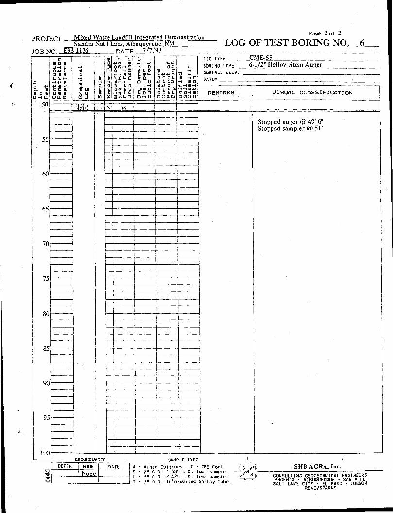
PROJECT Mixed Waste Landfill Integrated Demonstration Sandia Nat'l Labs, Albuquerque, NM
Page 2 of 2
LOG OF TEST BORING NO. 6 JOB NO. E93-1136 .DATE, V7/93
r a « • e n
D - H 1 L
c D O B 3-H 0 0+J C 3 • • C S.4J
•W+J M
c : i O K U o a t r
• u •w r a c a «. o a _i
: L JJO HI O P ) - I E 0 H E *- • • « \XH-J : »-< i 3 « a 0s> 11 0 ~tt L I.
3 •P -U •-< 0 tt L 0 C l t -u a D u n u n O - l 0
V--U » a K C «
4J gi 013 B4J U
H C L 3 O O I L
r o i o
« H C ••< • 0 <•--<••-<
C O H I 3 tOO U
RIG TYPE CME-55 BORING TYPE 6-1/2" Hollow Stem Auger SURFACE ELEV. DATUM
REMARKS VISUAL CLASSIFICATION
50
55
58
Stopped auger @ 49' 6" Stopped sampler @ 51'
60
65
70
75
80
85
90
95
100 GROUNDWATER
DEPTH HOUR DATE V None X
SAMPLE TYPE
A - Auger C u t t i n g s C - CME Cortt. S - 2" O.D. 1 .38" l . D . tube s a n p l e . U - 3" O.D. 2 . 4 2 " i . D . tube sample . T - 3" O.D. t h i n - w a l l e d Shelby t u b e .
SHB AGRA, Inc. CONSULTING GEOTECHNICAL ENGINEERS PHOENIX • ALBUQUERQUE • SANTA FE SALT LAKE CITY - EL PASO - TUCSON RENO/SPARKS
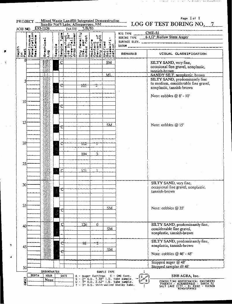
PROJECT Mixed Waste Landfill Integrated Demonstration Sandia Nat'l Labs, Albuquerque, NM
Page 1 of 1
LOG OF TEST BORING NO. 7 JOB NO. E93-1136 HATF 7/8/93
X n. * • c • O-HIL
c • OK 3-< U 0-M C 3 • • C 1.4J
-t*J » *> M-i C C « O • • oa.tr
• u «» r a * i i. i o .
: L O O H E 0 - I E V- • • C » - t i 3 « a o s t o (D-4V.T]
3 •H 0 • S. 0 c ev-ii a Q u
i.n 3 D-l 0
t - * j o r « Q ] C C »
4 J I H 3 **> 0
•-4 C 1 - 3 O D I L EO0.O
I ••i
T5 V-I H C •H « 0 •H-4 B*J C D-H 8 3 ( 0 0 0
RIG TYPE CME-S5 BORING TYPE 6-1/2" Hollow Stem Auger SURFACE ELEV. DATUM
REMARKS V ISUAL C L A S S I F I C A T I O N
SM SELTY SAND, very fine, occasional fine gravel, nonplastic, tannkh-hrown
ML. SANDY STLT, nonplastic. brown
10
15
20
25
30
35
40
45
50
I •165-
t 1 _SM_
I -112-
104
_C JL2L
SILTY SAND, predominantly fine to medium, considerable fine graveL nonplastic, tannish-brown
Note: cobbles @ 8' -10 '
Note: cobbles @ 15'
I SM
126 _SM_
SILTY SAND, very fine, occasional fine gravel, nonplastic, tannish-brown
Note: cobbles @ 35'
SILTY SAND, predominantly fine, considerable fine gravel, nonplastic, tannish-brown
-9S-
SM
SILTY SAND, predominantly fine, nonplastic, tannish-brown
Note: cobbles @ 46' - 48'
Stopped auger @ 48' Stopped sampler @ 48'
2
GROUNDWATER DEPTH HOUR DATE
None
SAMPLE TYPE A - Auger Cuttings C - CHE Cont. i S - 2" O.D. 1.38" 1.0. tube sample. — U - 3" O.D. 2.42" I.D. tube sample. ' T - 3" O.D. thin-walled Shelby tube.
SHB AGRA, Inc. CONSULTING GEOTECHNICAL ENGINEERS PHOENIX • ALBUQUERQUE • SANTA FE SALT LAKE CITY - EL PASO - TUCSON RENO/SPARKS
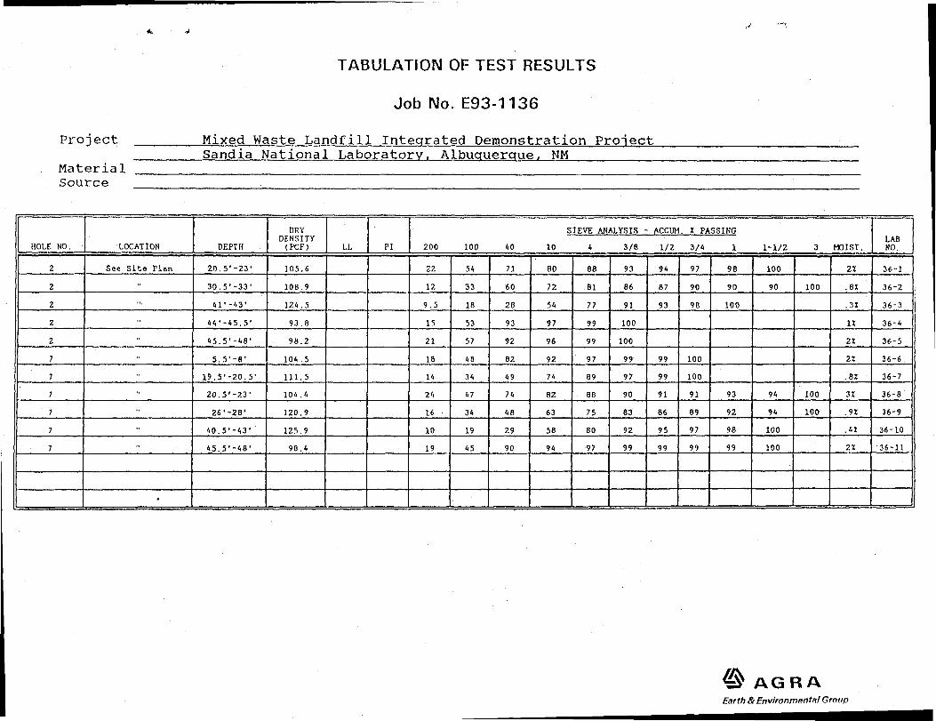
TABULATION OF TEST RESULTS
Job No. E93-1136
Project Mixed Waste Landfill Integrated Demonstration Project Sandia National Laboratory, Albuquerque, NM
Material Source .
HOLE NO. LOCATION DEPTH DRY
DENSITY (PCF) LL PI
SIEVE ANALYSIS - ACCUM. X PASSING 200 100 40 10 4 3/8 1/2 3/4 1 1-1/2 3 MOIST.
LAB NO.
2 See Site Plan 20.5'-23' 105.6 22 54 71 80 88 93 94 97 98 100 21 36-1 2 •• 30.5'-33* 108.9 12 33 60 72 81 86 87 90 90 90 100 .a: 36-2 2 ••• 41'-43' 124.5 9.5 18 28 54 77 91 93 98 100 .31 36-3 2 •• 44'-45.5' 93.8 15 53 93 97 99 100 1Z 36-4 2 45.5'-48' 98.2 21 57 92 96 99 100 2Z 36-5
5.5'-8' 104.5 18 48 82 92 97 99 99 100 2Z 36-6 •• 19.5'-20.5' 111.5 14 34 49 74 89 97 99 100 .81 36-7 •• 20.5'-23' 104.4 24 47 74 82 88 90 91 91 93 94 100 3Z 36-8 •• 26'-28* 120.9 16 34 48 63 75 83 86 89 92 94 100 .91 36-9
40.5,-431 125.9 10 19 29 58 80 92 95 97 98 100 .41 36-10 •• 45.5*-48' 98.4 19 45 90 94 97 99 99 99 99 100 ZX 36-11
•
Federal Agencies f US Department of Energy (2)
Office of Technology Development Attn: S. Chamberlain, EM-551, Trevion II 1901 Germantown Rd Germantown, MD 20874-1290 US Department of Energy Albuquerque Operations Office ETN Attn: Pam Saxman Pennsylvania/H Street Albuquerque, NM 8 7116
State Agencies NM Environment Department Secretary of the Environment Attn: J. Espinosa 1190 St. Francis Drive Santa Fe, NM 87503-0968
Laboratories/Corporations Brookhaven National Laboratory Attn: J. Heiser P.O. Box 5000 Bldg. 830 Upton, NY 11973 Pacific Northwest Laboratory Attn: M. Peterson P.O. Box 999, MSIN P7-41 Battelle Boulevard Richland, WA 98052
Golder Associates Attn: Carl Einberger 4104-148th Avenue, NE Redmond, WA 98052 EG&G Idaho, Inc. Attn: K. Kostelnick P.O. Box 1625, MS 3930 Idaho Falls, ID 83415-3970
Libraries Thomas Brannigan Library Attn: D. Dresp
> 106 W. Hadley St. Las Cruces, NM 88001
* Government Publications Department Zimmerman Library University of New Mexico Albuquerque, NM 87131
Internal MS Orq 0719 6621 MWLID Library 0719 6621 B. P. Dwyer (6) 0756 6607 G. Allen 1326 6313 R. Finley 1322 6121 E. Ahrens 0899 7141 Technical Library (5) 0619 7151 Technical Publications 0100 7613-2 Document Processing for
DOE/OSTI (10) 9018 8523-2 Central Technical
Files