feasibility n;ava aill/ite/i of new selection … · it is concluded that the award criteria for...
TRANSCRIPT

FEASIBILITY OF NEW SELECTION CRITERIA FOR THE VILLARD C. SLEDO-ETC(U)AO+, 07R N;AVA L PR ADUT SCHOOL MOTRE A iI Aill/ITE/I
EIEEEEEIIEEIIEEEEEIIIIIEEIIEIEEEEIIEEIIII

NAVAL POSTGRADUATE SCHOOLo Monterey, California
THESISFEASIBILITY OF NEW SELECTION CRITERIA
FOR THE VILLARD C. SLEDGE AWARD
.: Iby
Richard A. Clute
June 1981
Thesis Advisor: J. W. Creighton
Approved for public release: distribution unlimited.
- Y

SECURITY CLASSIFICATION OF TISPAGE MW ae De DEnt i E D H T)C~ NREPW OCUMNTATIN FAE stong COMPL&TV111 FPOW
7 Feasibility of New Selection Criteria for the Master's, Thesis,-~Villard C. Sledge Award. 0.PROMN RG EOTM E
17. AuTNOCfe) 8. CONTRACT 601 GRANT NUUNER()
Richard A.!Clute
S9. PERFORMING ORUANIZATION NAME AND ADDRESS 10. PROGRNAM ELEMENT.U PRJICT. TASK
Naval Postgraduate SchoolMonterey, California 93940
It. CONTROLLING OFFICE NAME AND ADDRESS 12. REPORT GATE
Naval Postgraduate School (/( June IV81Monterey, California 93940 " 52
14. MONITORING AGENCY "AMC & ADDARSSOit aUftnoI fto Cainevellnj Offleej 1S. SECURITY CLASS. (et this."
ISA. MckosaSIc A Tt aii DOWG aR AING-m
16. DISTRI11UTION STATEMENT (of Well ASOpet)
Approved for public release; distribution unlimited.
17. DISTRIGuTION STATEMENT (of the abonist on"e iII GeeS W. It iffe h~em *eert
IS. SUPPLEMEN911CTARY NOTES
so. Key WORD$ (Cameejue 09"Vro 1Wa it nSee*"& -d JAMO& 1W MOOS Rmle)
Intermediate maintenanceAircraft enginesMaintenance Data Systems
20. ASISTRACT (Covittae an reerse s 01 noo.mie ai Idwt by 61.0k w)
4 The Villard C. Sledge Memorial Maintenance Award is a valuable tool to main-tain maintenance excellence and morale within the naval aviation community.This annual award is given to selected Intermediate Maintenance Activities foreach model engine within each degree of maintenance.
This thesis evaluates the data sources used in the selection of the award, in-cluding those from organizational through intermediate level maintenance.
oo0 1 JN7 1473 soirloOr 1F Nov sS is 01. IFSii (age1) /N 002*14- I SCURITY CLASSIFICATION Oi TIG PAGE (WM 0. De1WO

gum?,"V C ASS&eIVIGIO TW~I 060O5V~d ft..e 3.mu.e.
The use of the three degree maintenance concept in the evaluation is dis-cussed. The Maintenance Data System is described with emphasis on thedata flow.
It is concluded that the award criteria for selection is satisfactory atthis time and should only be changed by reducing the number of enginesinducted for First and Second Degree maintenance in the selection criteria..
i
z
DO For. 1473k W' 0 2-i014-6610 *1CUM-9? e a,g.',Olut tilJes., Dw6 * E, O Im,,.E

Approved for public release; distribution unlimited.
Feasibility of New Selection Criteriafor the Villard C. Sledge Award
by
Richard A. CluteCaptain, United States Marine Corps
B.B.A., Western Michigan University, 1973
Submitted in partial fulfillment of therequirements for the degree of
MASTER OF SCIENCE IN INFORMATION SYSTEMS
from the
NAVAL POSTGRADUATE SCHOOLJune 1981
Author:
Approved by:___________________________Thesis Advisor
Second Reader
Dean of Information and Policy Sciences
3
SI I5 211 iiii

ABSTRACT
The Villard C. Sledge Memorial Maintenance Award is a valuable
tool to maintain maintenance excellence and morale within the naval
aviation community. This annual award is given to selected Intermediate
Maintenance Activities for each model engine within each degree of
maintenance.
This thesis evaluates the data sources used in the selection of
the award, including those from organizational through intermediate
level maintenance. The use of the three degree maintenance concept in
the evaluation is discussed. The Maintenance Data System is described
with emphasis on the data flow.
it is concluded that the award criteria for selection is satisfactory
at this time and should only be changed by reducing the number of en-
gines inducted for First and Second Degree maintenance in the selection
criteria.
4
TABLE OF CONTENTS
I. INTRODUCTION ----------------------------------------------- 7
A. PROBLEM STATEMENT--------------------------------------- 7
B. OBJECTIVES --------------------------------------------- 8
C. THESIS PLAN -------------------------------------------- 8
D. THESIS OUTLINE ----------------------------------------- 8
II. BACKGROUND----------------------------------------------- 9
A. BIOGRAPHY OF VILLARD C. SLEDGE -------------------------- 9
B. THE VILLARD C. SLEDGE AWARD-----------------------------10o
C. INTERMEDIATE LEVEL MAINTENANCE-------------------------- 16
D. THREE DEGREE INTERMEDIATE LEVEL MAINTENANCE ------------- 19
E. MAINTENANCE AND MATERIAL MANAGEMENT SYSTEM -------------- 20
III. INTERMEDIATE LEVEL ENGINE MAINTENANCE----------------------- 21
A. GAS TURBINE ENGINE ------------------------------------- 21
IV. MA1NTENANCE DATA SYSTEM----------------------------------- 28
A. PURPOSE OF MDS---------------------------------------- 28
B. DATA FLOW--------------------------------------------- 29
C. INPUT CONCEPT AND APPROACH ----------------------------- 31
D. ADMINISTRATION---------------------------------------- 32
E. DATA VALIDATION AND CORRECTION-------------------------- 3S
F. VIDS/MAF FORM ----------------------------------------- 36
G. SUMM.ARY---------------------------------------------- 3
V. 3-M AVIATION INFORMATION REPORT ---------------------------- 40
A. AIMD ENGINE MAINTENANCE EVALUATION REPORT --------------- 40
B. ACTION TAKEN CODE ------------------------------------- 43

C. MALFUNCTION DESCRIPTION CODE---------------------------- 45
VI. CONCLUSIONS----------------------------------------------- 46
APPENDIX A: TERMINOLOGY ----------------------------------------- 48
LIST OF REFERENCES---------------------------------------------- 49
BIBLIOGRAPHY---------------------------------------------------- 51
INITIAL DISTRIBUTION LIST ---------------------------------------- 52
6

I. INTRODUCTION
A. PROBLEM STATEMENT
The Villard C. Sledge Award was named after a United States Navy
Lieutenant Commander who devoted his entire 30-year naval career to Naval
Aviation Maintenance. The award was inaugurated to provide recognition
for Intermediate Maintenance Activities (IMA), that must closely mirror
the high professional goals, and achievements associated with this
pioneer of Naval Aviation Maintenance. This award was intended to pro-
vide an incentive for the continued search fcr maintenance excellence in
the Intermediate Maintenance Activities community. This award is current-
ly won by the activities reporting the highest number of engines processed,
and the highest percentage of inducted engines repaired.
During the past years, there have been numerous complaints that some
activities may be manipulating their reports so as to inflate the numbers
upon which the award is based. For example, if a need for repair, even
minor repair, is discovered while an engine is undergoing an "I" level
inspection, the inspection Maintenance Action Form (MAF) will be closed
out. This engine will then be inducted for repair. Upon completion of
the repairs, the repair Maintenance Action Form will be closed out and
the engine reinducted to complete the unfinished inspection. The Inter-
mediate Maintenance Activity may then receive multiple credit for a
single ready-for-issue (RFI) engine. There is also evidence that the
fear of reducing their score may induce Intermediate Maintenance Activi-
ties to retain engines for local repairs along with complaints that some
7

are required to perform extensive repairs that could be processed more
economically by other activities. Many Intermediate Maintenance Activi-
ties have complained that they are required to perform extensive repairs
for which they receive no credit, i.e., Intermediate Maintenance Activi-
ties receive no credit for the Ready-for-issue assemblies and assistance
they provide 10"1 level activities such as in the support of over-the-wing
T-56 turbine changes.
B. OBJECTIVES
The objective of this research is to consider methods of determining
and improving the Data Sources for the selection of winners of the
Villard C. Sledge Award.
C. THESIS PLAN
Research was accomplished by first conducting an extensive literature
search and then into existing ADP systems such as the Maintenance and
Material Management (3M) System to ascertain the type, quantity, and
quality of the data contained therein. Using this information, make a
determination as to the source or sources of data best suited to support-
ing the selection criterion to be developed.
D. THESIS OUTLINE
The second chapter will provide background information to support
subsequent chapters. First, a brief history of Lieutenant Commander
Villard C. Sledge and the award named after him. The Intermediate level
Maintenance will be briefly discussed followed by the Three Degrees of
maintenance and the Maintenance and Material Management (3-M) System.
Chapter III will discuss the Intermediate level gas turbine engine
maintenance. Chapter IV goes into the Maintenance Data System and
8

discusses the purpose of the MDS, data flow, input concept, administra-
tion, correctness and validity, and the VIDS/MAF form. Chapter V de-
scribes the AIMD Engine Maintenance Evaluation Report.
II. BACKGROUND
A. BIOGRAPHY OF VILLARD C. SLEDGE
The Villard C. Sledge Award was named after Lieutenant Commander
Villard C. Sledge USN who was born on 6 November 1921 in Florence, Ala-
bama. After graduating from High School he enlisted in the Navy in
1941. He rose through the ranks having been appointed a warrant officer
on 1 October 1959 and retired from the Navy after 30 years on 31 July
1971 as a Lieutenant Commander. On 10 January 1972 he passed away and
was interred in Arlington National Cemetery.
Lieutenant Commander Sledge's entire Naval career was devoted to
Naval Aviation Maintenance. His major efforts were oriented toward
developing a comprehensive aviation maintenance system that would insure
an outstanding professional maintenance program with safety of operation
being the paramount goal. In recognition of those efforts, he was hand-
picked by flag rank and designated as project manager to establish a
program that would resolve specific maintenance problem areas.
Because his technical knowledge in the aviation maintenance field
was recognized and appreciated at all levels of naval aviation manage-
ment and aviation commercial contractors, it was only fitting that the
award for excellent performance at the intermediate level of jet engine
repair be named after him. [Ref. 1]
9.

B. THE VILLARD C. SLEDGE AWARD
Determination of the award recipients is based on two parameters:
The number of engines processed and the percent of accomplishment, while
concurrently adhering to the high maintenance standards which produce a
completely thorough and professional work process. These maintenance
standards require that accurate documentation of all maintenance actions
be maintained by all activities and that the management of monthly and
quarterly maintenance reports be utilized to monitor the actual shop
process versus documentated shop process.
"Percent Accomplishment" is determined by engines which have either
been repaired, tested and returned to service, inspected, or preserved
and packaged as directed by higher authority for return to Designated
Rework Point (DRP) in accordance with OPNAVINST 4790.2. This number
will be reflected as a percentage of the total number of engines pro-
cessed. A "Beyond Capability of Maintenance (BCM)" engine is counted as
an asset when computing the percent accomplishment. A BCM engine is one
that is forwarded to another maintenance activity because the forwarding
activity is unable to perform the necessary maintenance. The BCM rate,
expressed as a percentage, is the number of BCM engines divided by the
total number of engines processed. Although high time engines and engines
directed by higher authority are included in the BCM rate, they are also
counted as an asset.
The selection of the most excellent intermediate maintenance activity
for each model engine is based on the following information and procedure:
In the Naval Air Systems Comand Headquarters, the Maintenance Policy and
Engineering Division will request a 3-M report on all engines
10

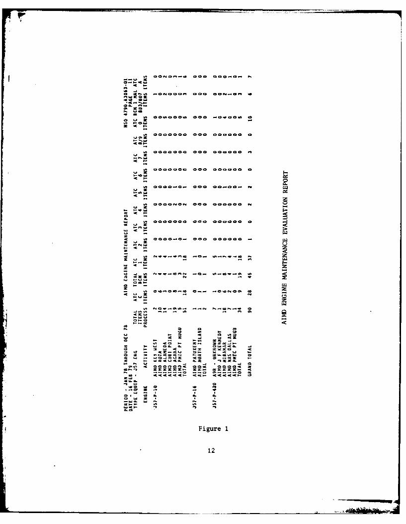
(Figures 1 and 2) and will outline the information in a modified report
(Figure 3). This report will highlight two important parameters. First
the number of engines processed and second the percent of accomplishment.
Those two parameters form the axes of the grading graphs (Figures 4, 5,
and 6).
Each intermediate maintenance activity will be plotted on the appro-
priate degree graph which is divided into sections by diagonal lines with
a negative slope of 1 to 4 that will ensure the number of engines pro-
cessed is equally weighted with the percentage of accomplishment. If
more than one activity is in the highest section, lines of the same slope
will be passed through the two points to determine the award recipient.
If a winner is still not determined by these methods, then the next
criterion to be considered is the percentage of repaired engines.
[Ref. 21
Only those intermediate maintenance activities which have been desig-
nated under the three degree program for a particular engine model for
the full calendar year will be considered. If an intermediate ma.-Itenance
activity has changed in degree assignment in the calendar year, the inter-
mediate activity will be considered for an award at the lowest degree held
during that year.
In order to qualify for an award, an intermediate maintenance activity
must also meet the following minimum requirements:
1. A First Degree Activity must process a minimum of 50 engines
of a particular model and must have repaired 25 or more engines.
See Figure 4.
10'oS SM F.W 040 0 00 ot =
dc L a
*0.
006ns~ooo.A 0400 -0OvoUS
,A 000000= 000o 000000 0
us 000000 000 =00=000 m'
4 -w
.c =
us 000 -0.- 0== 00..00.. 1%
LI =
-us
4 >-
-C 0000-uo- 000 00000 94
b.- . L
z k- =
LI -
zw LI
0 2c
3, w, -C 2.0. n- 0 x
0 I- -c - . : c I-
4c LI c -C 9.a
Lj MJ
66. As us -- - -C- Cdc- C-
a. M
IFigSMeLI
us 4012

IA CC CC ~ ~4j 0- PA044 OMI M*,4 In
I. -
o; 4
'.4 z
4 - -j --
IA~~~~ C!IICI~CO
o oIA 4O-J ~ C I C NI -!P:C 1!4
. wsO C C! I IA C!C C!C A
0 4I- IA -
CC >
'A
-p 0-
IA C CCOCO CC C C
CM - MO-WC3
C; - ; ---IA o C C C O C Ca
4'inw. -C
w 4A _jas 4A=,--o
C~aO-w z -C NCa a
= 4 A mCAC C CC C C1
CLU
IL 0
Fiur 2C- ,AONA
13INC N.NII

% ~ 9
ACCOMPLISHED '- "- -aa____________ &n -co w a_ _ _ _ _ _
ATC A ITEMS egaTESTED RETURNED
ATC C ITEMS ' f aRPIE
MAL 803 ITEMS 0 C HIGH TIME 9
ATC-O ITEMS CD U% INSPECTED c
ATC-8/9 ITEM4S C'0 0 BUDGET/CONDEMN "
% ~-cATC-7 ITEMS ~aaaECS
TECHNICAL DATA
-T- ITM BACKLOGk
%ATC-4 ITEMS ~ aaPRSi
ATC-3 ITEMS 0 SKILLS
% EQUIPMENT ANDATC-2 ITEMS FACILITIES
I ilATC-1 ITEMS -Wq NOT AUTHORIZED
TO %cc q -WBEYOND CAPABILITYTA BH AINTENANCE
TOTAL ITEMSPROCESS c
LA'i
= 1 =
ca
F. 2ca a c~
LAS A
14

I -4
CD
-41
0&
-a
-U =
-3 CO - 4
-~~~L -4~it
0 % -0 co-~ - 4,j.LO
-~~ -A
140r - L. I- I I I I L -- - -~~-0 L
-is

2. A Second Degree Activity must process a minimum of 20 engines
of a particular model and must have repaired 10 or more engines. See
Figure 5.
3. A Third Degree Activity must process a minimum of 10 engines of
a particular model and must have repaired 5 or more engines. See
Figure 6.
A certificate of excellence will be awarded to the most superior in-
termediate maintenance activity at each degree of intermediate mainten-
ance for each engine model. This certificate will be known as The
Villard C. Sledge Memorial Maintenance Award, in honor of a highly de-
voted naval officer whose dedicated service is cited in Section (A) of
this chapter.
C. INTERMEDIATE LEVEL MAINTENANCE
Intermediate maintenance is that upkeep maintenance which is the
responsibility of, and is performed by, designated maintenance activities
in support of using organizations. This work normally consists of cali-
brations; off-equipment repair or replacement; repair or replacement of
damaged or unserviceable parts, components, or assemblies; the manu-
facture of certain unavailable parts. Intermediate maintenance may in-
clude the performance of certain periodic inspections and providing
technical assistance at the organizational level. The intermediate
level of maintenance includes the following:
1. Repair, test, inspection, modification and/or check of aero-
nautical components/equipments and related support equipment.
2. Intermediate level calibrations of designated equipments.
3. Processing of aircraft components/equipments stricken
16

I /I-
- V 0 CA- - - - jtiI -I 2~VL.-cc u1~
CD~ p~
0 U.. CD
LLA v0
LL.
- -L- - - -
vi - - .-..-~~~~~~ ~C - - -- - - -
-4H
1N3WHSIldWO33V %
17

j I A
II A
0 c
ex4 LU
C-)
I I
U
IFIv - -vL
mm z o -. -o L. -
iNWSldO3 %
-H-.10

from aircraft.
4. Technical assistance, when required, to the organizational
levels supported.
5. Perform selected functions normally accomplished at depot
level only.
6. Incorporate designated technical directives. [Ref. 3]
D. THREE DEGREE INTERMEDIATE LEVEL MAINTENANCE
Not every activity classified as an intermediate maintenance activ-
ity can perform the identical maintenance as some other intermediate
levels because each is not provided the identical level of support. It
is for this very reason that the concept of three degree intermediate
level maintenance has been developed.
The objective of the concept is to provide a consistent framework
for all intermediate level activities to perform various depths of
maintenance on components. The definition provided earlier for the in-
termediate level maintenance still applies; however, further considera-
tion is given to both the functions which can be performed on a component,
and the resources required to accomplish the functions. Subsequently,
the maintenance functions and corresponding resources required are cate-
gorized into one or more of the three degree classes. The structure of
the three degree concepts is such that the least difficult functions are
classified as third degree; slightly more difficult functions are classi-
fied second degree; the most difficult functions are classified first
degree. [Ref. 4]
Intermediate levels are assigned specific degree maintenance responsi-
bility on a component-by-component basis commensurate with their
19

respective ability/need to perform various depths of maintenance. The
degree maintenance responsibility assigned to an intermediate level is
in consonance with mission requirements. An activity will not normally be
assigned a degree of maintenance which would not allow it to meet its
mission requirements. A significant characteristic of the three degree
concept is that assignment of maintenance functional responsibility is
made on a component-by-component basis and in accordance with individual
maintenance activity support requirements.
E. MAINTENANCE AND MATERIAL MANAGEMENT SYSTEM
The Standard Navy Maintenance and Material Management (3-M) System,
directed by the Chief of Naval Material (CNM), has been in operation at
the organizational and intermediate levels since early in 1965. The system
is designed to collect and process data in order to provide informational
reports concerning the maintenance of Navy and Marine Corps equipments.
The 3-M System incorporates both the use of a Planned Maintenance System
(PMS) and a Maintenance Data System (MDS). Through the use of the PMS, the
maximum operational efficiency of all Fleet equipments is attained and
maintained, equipment downtime is reduced to a minimum consistent with
good maintenance practice, and the cost of maintenance in both money and
man-hours is reduced. Through the use of the MDS, a means is provided for
gathering data directly related to maintenance. The data can then be
analyzed and displayed to show the relationship of corrective maintenance
to preventive maintenance which in turn can be used by management to im-
prove the maintenance effort. [Ref. 5]
The System is designed to provide command, field activities, and other
data users access to information drawn from the exceptionally broad data
20
of the 3-M System. The data will provide in-depth information concerning
the expenditure of resources, the maintenance of equipments, and the nature
of equipment failures. This information will prove useful in defining
equipment problem areas in terms of their effect upon reliability, avail-
ability, maintainability, and cost.
III. INTERMEDIATE LEVEL ENGINE MAINTENANCE
A. GAS TURBINE ENGINE
The Naval Aviation Maintenance Program (NAMP) provides the basic con-
cepts and guidelines which represent the engine maintenance program
policies of NAVAIR. The objectives of the program are to prescribe
policy and procedure for the application and monitoring the performance
of maintenance required in support of gas turbine engines at various
levels of maintenance. The Complete Engine Repair (CER) Program was
initiated in 1958 to establish the necessary support criteria and manage-
ment guidelines to achieve shorter turnaround times, increasing time be-
tween overhauls and reducing the number of unserviceable engines in the
Navy inventory. Another concern which promoted the development of the CER
Program was the awareness by management of the sizeable inventory dollar
investment in aircraft engines and the continually rising cost of new
engine models. The CER Program provided management with the capability to
* establish controls so as to reduce and maintain a lower new acquisition
requirement for aircraft engines. [Ref. 6]
The three degree concept has evolved with the continual efforts of
maintenance management to improve aircraft gas turbine engine maintenance
21
. ......

support posture. This concept is intended to provide specific guide-
lines and responsibilities throughout the aviation maintenance community
for the management of all gas turbine engines installed in the Navy and
Marine Corps aircraft. It is intuitively obvious that is is not economi-
cally feasible to establish identical maintenance capability at exh and
every intermediate maintenance activity (IMA), for each and every air-
craft engine Type/Model/Series supported. Additionally, the operating
scenario of each activity limits the extent to which it can accomplish
certain maintenance functions. That is, shore-based IMA's and afloat
IMA's are equipped differently by virtue of the environment in which
they are located. The three degree maintenance concept recognizes the en-
vironmental factor, in terms of an IMA having the capability to accommo-
date the resources required in support of a component. Certain types of
support equipments will require more space than a ship can afford; cer-
tain test requirements cannot be accomplished aboard ship for lack of
proper facilities. These type factors for determining the most effective
and practical assignment of maintenance responsibilities to each inter-
mediate level activity is considered by the three degree concept.
Appendix A contains terminology to be used in the discussion that
follows on aircraft engine maintenance. These engine maintenance activi-
ties are not designated a specific degree maintenance responsibility
across-the-board. That is, it would not be correct to say that NAS
Miramar is a first degree activity for all gas turbine engines. Rather,
NAS Miramar is a first degree activity for a specific gas turbine engine
Type/Model/Series: e.g., the J-79, all Type/Model/Series; the J-57-22/420.
Additionally, NAS Miramar is authorized second degree maintenance
22

responsibility for the T-56-8/425/426. It follows that NAS Miramar is
not authorized and is not responsible for performing first degree mainten-
ance of the T-56-8/42S/426. It is conceivable that, in addition to per-
forming first degree maintenance for the engine Type/Model/Series for
which the activity has first degree responsibility, the activity would
be expected to support nearby activities not having first degree capa-
bility/authority. An activity having a lesser capability may seek
support from a higher level activity contingent on the higher degree
classified activity being capable of accommodating the lesser capable
activity. This characteristic of the three degree concept also applies
to similar criteria for second and third degree activity interfaces.
The whole process commences at the Organizational Maintenance Activ-
ity (OMA) level. A decision is required at the OMA level for each reported
engine malfunction as to the type maintenance actions necessary to
correct the malfunction. Typically, corrective actions not requiring
removal of the engine from the aircraft are performed at the OMA through
removal and repair/replacement of defective component parts. Engines
requiring removal from the aircraft are processed through the local
supply system for disposition. Depending upon the nature of the mal-
function and the type maintenance required to return the engine to ser-
viceable condition, a determination is made whether or not corrective
actions can be accomplished by the local IMA. Documentation in the form
of NAVAIR Notice 4700 identified each activity and their respective
authorization to perform specific degree maintenance functions by air-
craft engine Type/Model/Series. [Ref. 7] Additionally, individual
engine Maintenance Instruction Manuals (MIM) are structured so as to
23
If

correlate maintenance functions and associated support resources required
for specific maintenance operations. The Aircraft Intermediate Mainten-
ance Departments (AIMD) can readily determine if the engine can be
repaired locally. Maintenance requirements beyond the local intermediate
level capability require that the engine be processed to the nearest
activity having the capability, and capacity, to effect necessary
corrective actions.
Figures 7 and 8 illustrate the decision making process for purposes of
screening rejected engines. If the malfunction of the engine cannot be
corrected at the organizational level, the defective engine is forwarded
to the local supply system and a replacement engine, if available, is
returned to the organizational activity. The rejected engine presently
in the local supply system is considered in terms of the degree of main-
tenance required and the autorized degree of maintenance for the local
intermediate maintenance activity. Engines beyond the capability of the
local activity are forwarded to the appropriate level which can effect
appropriate corrective action.
Engines processed at CER/First Degree are subject to additional de-
tailed screening criteria as indicated in Figure 8. Considerations are
made in terms of the Maximum Operating Time (MOT) which refers to the
amount of time an engine has been in operation relative to its scheduled
overhaul. If the engine has exceeded 7S% Maximum Operating Time, it must
be forwarded to its Designated Overhaul Point (DOP). The net effect of
this criteria is to not expend large amounts of manpower, materials and
money to effect a CER/First Degree Repair at such a close period in time
24

ENSIME IS BEYONID OMALEVEL OF REPAIR
SUPPLY
AID
CER/ FlRST * OR S7(COf;D ORREPAIR THIRD DEGREE REPAIR OR OVE-RHAUL?
THIRD 01 OP VIA SUPPLY
IS AI .M A CER FOR TYPE/'IJDEL/SERIES?
CER/FIRST DEGREE
AIRCRAFT INTERMEDIATE MAINTENANCE DEPART4E ' TSCREENING SEQUENCE PROCEDURE FOR REJECTED ENGINES
Figure 7
25

ow
YESIS REPAIR BEYOND DOP VIA SUPPLYFIRST DEGREE IMAAUTHORIZATION?
NO
IS ENGINE PAST Y DOP VIA SUPPLYEITHER:1. 75 MOT? OR2. IS DMH TO REPAIR 1110
GREATER THAN 80% IS DMH TO REPAIR GREATERDIH TO OVERHAUL? YES THAN 800 OMH TO OVERHAUL?
IS ENGINE REPAIRYETIME EXPECTED TOBE IN EXCESS OF30 DAYS? oN
YES DOWel?
(REQUEST BCMNO AUTHORIZATION)
AUTHOR. -FUNCTIONAL- - ICOMMANDER
' ---.-E- DOP VI SUPPL Y
WORK STOPPAGE NO (REQ MAT NAVAIRSYSIS ITEM AVAILABLE CMEFROM ASO? EGN
: L I I l AVAIRi ' I ' AR , I AWP H REWORKFAC
' | IFIRST DEGREE/CER, OR REPAIRI _ ._S NECESSARY
L SUPPLY
FIRST DEGREE INTERMEDIATE MAINTENANCEACTIVITY SCREENING SEQUENCE FOR
REJECTED ENGINES
Figure 8
26

to the scheduled overhaul. In general, a CER/First Degree Repair
effort involves a near-complete teardown of the engine. Then, if the
75% Maximum Operating Time criteria applies, it would be more cost effec-
tive to institute the overhaul rather than the CER/First Degree Repair.
Additional criteria which apply in the case of CER/First Degree
maintenance includes:
1. Direct Manhours (DMH) required to effect repair compared
to DMH's to effect overhaul.
2. Turnaround Time (TAT) required to effect repair in excess
of 30 days.
3. Engine state of teardown.
Each criteria functions to ensure that a rejected engine is maintained at
the lowest practical and cost effective level. [Ref. 8]
A significant feature of the three degree concept as currently em-
ployed for intermediate level activities is that a procedure does exist
for an activity to either up-grade or down-grade its degree designation
commensurate with changes in support requirements. The procedure applies
for instances in which the complement of aircraft engine Type/Model/Series
changes significantly. Should the aircraft engine complement reduce in
quantity to a level that certain authorized maintenance functions are
not performed with as great a frequency, and, consequently, certain
resources are not effectively employed, the activity may submit a request
to NAVAIR for change in degree maintenance responsibility. Similarly,
an activity that experiences a significant increase in the requirements to
perform maintenance functions not previously authorized may do so through
the same channels as in the former case. NAVAIR receives and evaluates
27

all proposed changes in degree maintenance designations. A recommendation
is forwarded to the Chief of Naval Operations by NAVAIR based upon its
evaluation of each request. The Chief of Naval Operations either approves
or rejects the request. Appropriate changes are made throughout the
maintenance community in consonance with the Chief of Naval Operations
decision. All assignments of first, second, and third degree designated
activities are recorded in NAVAIR Notice 4700 which is updated annually.
[Ref. 9]
IV. MAINTENANCE DATA SYSTEM
A. PURPOSE OF MDS
The purpose of the Maintenance Data System (MDS) is to document,
analyze and employ data for the management of aviation maintenance and
material support. The MDS was developed as integral part of the 3-M Data
System to provide the data input to the Naval Aviation Maintenance Program
(NAMP). This system furnished data products which provide management
tools for the efficient and economical management of maintenance
organizations.
The 3-M Data System is sponsored by the Chief of Naval Operations
(CNO) and administered through the operating chain of command. Technical
support is provided by the Chief of Naval Material (CNM) and Naval Air
Systems Command (NAVAIRSYSCOM). The MDS is a management information sys-
tem designed to provide statistical data for use at all echelons for:
1. Maintenance personnel utilization
2. Equipment maintainability and reliability
28

3. Equipment configuration
4. Equipment readiness and utilization
S. Maintenance material usage
6. Material non-availability
7. Maintenance material processing times
8. Weapon system and maintenance material costing
The 3-M Data System is a handy, ready way to collect data for use primar-
ily by the fleet, and also for all the other users up and down the line.
[Ref. 101
B. DATA FLOW
It all begins at the Organizational level with a Visual Information
Display System/Maintenance Action Form (VIDS/MAF) which is the basic
source document. All the maintenance data is collected on a VIDS/MAF or
on a Support Action Form (SAF), including all adjustments that are made
(Figure 9). The VIDS/MAF collects the maintenance data at the source.
If a repairable component is involved in the maintenance action, a copy
will go with the repairable component to the Intermediate level. If
there's merely an adjustment to be performed, we may never do anything
more than set up one Maintenance Action Form and that, of course, goes
right to a data service facility. With the component that arrives at
the Intermediate level, copies of the VIDS/MAF are distributed, as will be
described later. If the component is repaired at the Intermediate level,
that will end the data flow at that point and forms will be sent to the
appropriate 1'cations. If it is Beyond Capability of Maintenance (BCM),
copies of the form will accompany the component to the Depot level.
[Ref. 11]
29
• .1 LL - L I

La3
a4
IM
IJ.10
Figure 9
30

C. INPUT CONCEPT AND APPROACH
The VIDS/MAF concept provides information in a concise form which
simplifies the maintenance documentation effort. It requires minimum
manpower and paperwork to maintain, gives maximum maintenance status
information to managers, and provides a uniform source document. The
VIDS/MAF is the prime source document for maintenance actions.* The
Support Action Form (SAF), is used to document manhours expended in the
maintenance comunity for actions in general support, various inspections,
corrosion control, etc. The Equipment Statistical Data (ESD) card,
captures readiness information for aircraft readiness; readiness and
utilization data for ground support equipment and training devices.
The Naval Aircraft Flight Record (Yellow Sheet) and Flight Readiness
Evaluation Data Sheet (FREDS) which is the Marine Corps yellow sheet are
filled in by the pilots for every aircraft flight or flight simulator
period to collect flight data.
Information collected by these 5ource documents is processed at the
local data services facility and 5ent in the form of punched cards or
tape to the Navy Maintenance Support Office (NAMSO). The type of input
data that is specified for the Maintenance Data System provides the
means by which the Navy measures the effectiveness of its equipment and
the planned maintenance systems. The forms used to record the input
data are geared to the way the Navy performs maintenance. Every avia-
tion weapon system is cycled through servicing, preflight, flight and
postflight, and back again to servicing. The equipment continues in
this cycle receiving support action until sufficient calendar time or
31

flight hours have accumulated to require scheduled maintenance to take
place. During scheduled maintenance, corrective maintenance requirements
are discovered. Repairs are made and the aircraft is inserted into the
cycle again. The majority of the maintenance is unscheduled when dis-
covered during the normal day-to-day operations of the equipment.
As stated before, the Organizational level of maintenance in the Navy
deals primarily with removing and replacing components. Once that de-
fective component is removed from the equipment, it is turned into the
Intermediate level of maintenance. It is screened and then turned into
a shop at the Intermediate level to be repaired, adjusted or found to
have no defect. It can also be beyond the capability of the Intermediate
level maintenance, in which case it is sent to the Depot level.
D. ADMINISTRATION
The supervisor of each work center is responsible for the management
of all aspects of the MDS at that level. This would include the collec-
tion and screening of source documents, and correcting the errors, if
any, on the daily audit reports. Communication and coordination with
the Analysis Section is paramount in solving any problems that may arise.
An Analysis Section is established in each organizational and inter-
mediate level maintenance activity to monitor, control, and apply the
MDS within the activity. As the contact point between the work centers
and the Data Service Facility (DSP), this section has the responsibility
for the management of all aspects of the MDS at the activity level.
The Analysis Section is responsible for the collection, screening, and
forwarding of all source documents. They must screen, distribute, and
32

analyze machine reports and train maintenance department personnel in
MDS documentation procedures. Communication and coordination with the
work centers and the DSP is essential to resolve any problem areas.
[Ref. 12]
The Data Service Facility (DSP) has the main responsibility of con-
verting the data entered on the source documents into machine sensitive
records, and to produce any prescribed outputs for the reporting organi-
zation and any external recipients as required (Figure 10). This output
includes a series of daily audit reports which the reporting activity
receives the day following submission of the source documents. These
reports are used to verify the previous dayls inputs. At the completion
of each month, the DSF provides monthly reports for each reporting activ-
ity, if requested, and forwards MDS data to higher commands and to the
central data bank at NAMSO. A history file must be maintained of the
current data until NAMSO notifies DSF that the data was received and pro-
cessed. The local DSP cannot modify standard computer software/operating
procedures. If a change is required, the change will be carried out by
the Lead Programming Activity.
The MDS is a very unique as it is required to operate on a wide
variety of Automatic Data Processing (ADP) hardware systems in a great
many geographic locations. This imposes a considerably complex pro-
granmming requirmt and complicates coordination and management of the
system. A Lead Programming Activity (LPA) has been designated to pro-
vide system analysis and pro gramming services for each facility with
identical ADP hardware. They are responsible for the design, documenta-
tion and maintenance of the ADP so as to operate the system successfully.
33

It a
Z
404
Lif
4.34

If any revisions in software are required, the LPA will prepare, distribute,
and implement the necessary changes.
The Navy Aviation Maintenance Support Office (NAMSO) has the basic
operation and central data base maintenance responsibility for the sys-
tem. Data pertaining to any aspect of the maintenance effort of material
usage may be extracted by management at any level of command. NANSO re-
ceives all transactions, using the VIDS/MAF and other source documents
from the fleet, Intermediate and other maintenance data contributors.
The data base is updated monthly from these inputs, and the output re-
ports are printed and distributed. The NAMSO also has the responsibility
for satisfying new requirements and maintaining the system in effective
operating order. [Ref. 13]
E. DATA VALIDATION AND CORRECTION
MDS source documents are forwarded to the DSF for machine processing
on a daily basis from the reporting activity. As data from the source
documents are extracted and converted to machine sensitive formats, each
data element that enters the MDS must be validated to a prescribed set
of validation specifications. In the case of relational validation,
only the data element failing validation will be flagged. If data is
found to be erroneous, that element will be flagged on the applicable
daily audit report and corrective measures must be taken.
To the maximum extent possible, data base errors should be corrected
as they are identified on a daily basis. Reporting activities will sub-
mit MDS source documents to their local DSF for processing on a daily
basis. If data errors are noticed during the key punch operation, the
DSF may elect to circle the erroneous/illegible data elements in red and
3S

return the source document to the reporting activity for correction and
resubmission. If the data errors are not noticed during the key punch
operation, the system will validate all input records and identify all
data errors on the applicable daily audit reports. (Ref. 14]
F. VIDS/MAF FORM
The VIDS/MAF Copy 1 is a five-part form which was recently developed
as the single document for use as a management tool and maintenance data
collection source. Prior to VIDS/MAF, there were 10 different forms
used to manage or collect data for the 3-M Data System. These forms
have just about all been eliminated by the VIDS/MAF.
To have complete documentation five copies are necessary. Maintenance
control retains the first part of each maintenance action form and keeps
it on the Visual Information Display Status (VIDS) board (Figure 11).
Maintenance control must have this status for every ongoing maintenance
action or pending maintenance action for the unit. The second part is
for Quality Assurance. They use this to determine trends on certain equip-
ment or on certain aircraft so as to prevent components on the aircraft
from breaking and requiring maintenance, time and time again. Two of the
parts must be forwarded to the functional shop which is actually doing
the work. The fifth and last part is kept in the aircraft discrepancy
book which the pilot reviews prior to flight.
Copy 2 of the VIDS/MAF serves as a suspense document for repairable
component pool management while the defective component is being pro-
cessed by the Intermediate Maintenance Activity (IMA) (Figure 12).
Upon completion of the IMA action the component is returned to the supply
36

No. AXE 0000o coPY 1 S PART FORA Dc.maimsftl
.0 CENTER aco ica. CONTRmOL AM 'gOaM& I e CO" WIN &%&*O K a - I am al
,DS MAP .. w . coo0^W&kA(W(5RIC 0 ~ACCMUAE)%M NOURS
___ ___ -101G o__________ _____ .-
_______________pal___ n_______ Iabakac .fll CT
_____ ____ ____ ____ __ 1 - - F -
""A ~ ~ rf- REOE/ ffE #4 -LE .NF ITE
0WII9 _____________
flciEN cl'L h REMOORDO
IIII f
" I - -- OICRpN
VIDS/MAP Copy 1
Figure 11
37

10 hS/UIP M p~ A ?W FI ar. rwd~e COPY 2IOACn iauAUTV AGSSj MNCt VICJS COPY)£IMotBUP'LYIDEPr VIOS COPYI
REPAIRCYCLE KEMOvEOOLD ITEM
MATERIAL DATA lCYL
OISCREPANC1
2a ft'sok STOCK WWWIA
JOB CONTROL NUMB ER Ili~**~ JENIe I~ . . I.'a"' I. TURN-IN OCU M N
VIDS/MAF Copy 2
Figure 12
38

organization, and at this point blocks 1-12 are completed by the Supply
Support Center and Copy 2 is submitted to the DSF for processing. By
the transaction code entry in block 12, this document records whether
the component was repaired by the IMA and returned to Ready-For-Issue
(RFI) status, or was Beyond Capability of Maintenance (BCM) at the IMA.
[Ref. 15]
G. SUMMARY
The main data-entry form of VIDS/MAF is supplemented by the Equipment
Statistical Data and Support Action Forms. These are the three basic
forms that are used to measure direct maintenance, maintenance performed,
readiness of the aircraft and the support manhours required to maintain
that level of readiness.
Analysis of the data input to the MDS will indicate the reliability
of equipment and efficiency of the maintenance and supply systems. The
VIDS/MAF form is used in the day-to-day management of the Naval Aviation
Maintenance Program (NAMP).
39

V. 3-M AVIATION INFORMATION REPORT
A. AIMD ENGINE MAINTENAN~CE EVALUATION REPORT
This quarterly and cumulative annual report contains a sumnmary of
the number of aircraft engines processed through an Aircraft Intermediate
Maintenance Department (AIMD) and the percent of engines accomplishment
(Figures 1 and 2). This data in the report is used by the Naval Air
Systems Command as a source for selecting the outstanding intermediate
maintenance activity for the Villard C. Sledge Memorial Maintenance Award.
[Ref. 16]
The data used in the report was obtained from reports submitted by
the AIMD/IMA under the Naval Aviation Maintenance and Material Manage-
ment System (3-M System). The 3-M report forms utilized are VIDS/MAF,
OPNAV forms 4790/59 and 4790/60, transaction codes 31 and 32.
Transaction code 31 is work performed on a removed repairable com-
ponent/item with no failed parts, awaiting parts, or engine identifica-
tion documented in the Failed/Required Material blocks. This code will
be used on engine documents only when the engine is not specifically
identified to a particular aircraft. Transaction code 11 has supporting
engine documents which are used for on-equipment work, not involving
removal of defective or suspected defective components/items. Also it
is used on supporting engine documents, not having a removal of a de-
fective or suspected defective component/item, when the engine is not
specifically identified to a particular aircraft and when the intermediate
level maintenance activities are closing out a maintenance action.
40

Transaction code 32 is used when work performed on a removed repair-
able component/item with failed parts, awaiting parts, cannibalization
actions, or engine identification documented in the Failed/Required
Material blocks.
This report is restricted to jet, turboprop and turbofan engines.
Below is the explanation for the contents of each heading in the report:
1. E.NGINE: The identification of the engine on which maintenance
was performed as reported on the VIDS/MAF document. The comment unknown
series (unk-series) will be displayed if the actual engine identification
cannot be determined.
2. ACTIVITY: The identification of the Aircraft Intermediate
Maintenance Department accomplishing the maintenance action.
3. TOTAL ITEMS PROCESSED: The number of aircraft engines processed
through an intermediate level maintenance activity as reported in
VIDS/MAF records with a transaction code of 31 or 32 when the main tenance
level is second or third and the Action Taken Code is A, C, 0, or 1
through 9.
j 4. ATC C ITEMS (Action Taken Code C Items): The number Of aircraft
engines which were repaired by the Aircraft Intermediate Maintenance De-
partment as reported in VIDS/MAF records with a transaction code of 31
or 32 when the Action Taken Code is C.
5. TOTAL BCM ITEMS (Total Beyond Capability of Maintenance items):
The number of aircraft engines beyond capability of maintenance by the
Aircraft Intermediate Maintenance Department as reported in VIDS/MAF
records with a transaction code of 31 or 32 when the Action Taken Code
41

is 1 through 9. Additionally, a separate breakdown of each BCM code 1
through 9 is provided.
6. ATC 0 ITEMS (Action Taken Code 0 items): The number of aircraft
engines on which major inspections were accomplished by the Aircraft
Intermediate Maintenance Department as reported in VIDS/MAF records with
a transaction code of 31 or 32 when the Work Unit Code begins with 03
and the Action Taken Code is 0.
7. BCM I MAL 803/807 ITEMS: The number of aircraft engines that
were removed for high time or directed by higher authority that were
beyond the repair capability of the Aircraft Intermediate Maintenance
Department as reported in VIDS/MAF records with a transaction code of
31 or 32 when the Action Taken Code is 1 and the Malfunction Description
Code is 803 or 807 (no defect--removed for time change or no defect--re-
moved directed by higher authority, respectively).
8. ATC A ITEMS (Actions Taken Code A items): The number of aircraft
engines where the reported deficiency could not be duplicated during
the Aircraft Intermediate Maintenance Department processing as reported
in VIDS/MAF records with a transaction code of 31 or 32 when the Action
Taken Code is A.
9. PERCENT BCM RATE: The Beyond Capability of Maintenance items
divided by the Total Engines Processed. Although high time engines and
higher authority directed engine removals (BCM 1, MAL Codes 803/807) are
included in the BCM Rate, they are also counted as an asset when computing
the percent accomplishment. A separate percentage is provided for each
Beyond Capability of Main tenance Code 1 through 9.
42

10. PERCENT ACCOMPLISHMENT: Those engines which have been repaired
(ATC C), tested and returned to service (ATC A), inspected (ATC 0),
preserved and packaged as high time for return to overhaul (HOW MAL 803),
or (HOW MAL 807) divided by the total number of engines processed.
[Ref. 17]
B. ACTION TAKEN CODE
The Action Taken Code is a one-character alphabetic or numberic code
that describes the action that has been taken (that is recorded on
VIDS/MAF). This code describes what action has been performed on the
item identified by the Work Unit Code (WUC). Action Taken Codes that
are utilized in the award selection are defined and explained below:
1. Code 1: BCM--Repair Not Authorized. This code is entered only
when the activity is specifically not authorized to repair the item in
applicable directions. This code will be used only if no other code is
appropriate.
2. Code 2: BCM--Lack of Equipment, Tools or Facilities. This
code is entered when the repair is authorized but cannot be performed
because of lack of equipment, tools, or facilities.
3. Code 3: BCM--Lack of Technical Skills. This code is entered
when repair is authorized but cannot be performed because of a lack of
technical skills.
4. Code 4: BCM--Lack of Parts. This code is entered when repair
is authorized but cannot be performed because required parts will not
be available within guidelines established by applicable directives.
5. Code 5: BCM--Fails Check and Test. This code is entered when
the activity's authorized level of main tenance is limited to check and
test only, and repair is required.
43

6. Code 6: BCM--Lack of Technical Data. This code is entered
when repair is authorized but cannot be performed because of a lack of
technical data.
7. Code 7: BCM--Beyond Authorized Repair Depth. This code is
entered when some level of repair beyond check and test is authorized
but the depth of repair required to return the component to an RHI con-
dition is beyond the activity's authorized repair level as indicated in
applicable directives, such as maintenance plans, maintenance manuals, etc.
8. Code 8: BCM--Administrative. This code is entered when repair
is authorized and feasible but not attempted due to budgetary limitations,
excessive backlog, or requirements in excess of materials. Such deter-
minations can be made jointly by the maintenance and supply officers.
9. Code 9: BCM--Condemned. This code is entered when a repairable
item is so severely worn or damaged that repair is not feasible. The
item is locally condemned and returned to the Supply Department for
survey, retrograde or scrap, as appropriate, in accordance with applicable
directives.
10. Code 0: This codc is used on all source documents recording
look-phase man-hours for Acceptance/Transfer, Conditional and Calendar
Inspections including the closeout of man-hours on the look-phase of those
inspections at the end of the reporting period.
11. Code A: Item of Repairable Material or Weapons/Support System
Discrepancy Check-No Repair Required. This code is used for all dis-
crepancies when checked and found that either the reported deficiency
cannot be duplicated, or the equipment is operating within allowable
tolerances. Adjustments may be made wnder this code if the purpose of
44 i.. =Woo-
the adjustment is to peak or optimize performance. When adjustments are
made, the Malfunction Code should reflect the reason for the adjustment.
If the purpose of the adjustment is to bring the equipment within allow-
able tolerances, Action Taken Code C should be used.
12. Code C: This code is entered when a repairable item of material
which is identified by Work Unit Code (WUC) is repaired. Repair in-
cludes cleaning, disassembly, inspection, reassembly, lubrication, and
replacement of integral parts; adjustments are included in this definition
if the purpose of the adju~stments is to bring the equipment within allow-
able tolerances. This code also applies to the correction of a discrepancy
on a Weapons/Support Systems, when appropriate. [Ref. 18]
C. MALFUNCTION DESCRIPTION CODE
The Malfunction Description Code is a three-character alphanumeric
code used on VIDS/MAP forms to describe the malfunction which causes the
maintenance action on the item described by the Work Unit Code (WUC). Con-
ditional malfunction codes are those which describe a malfunction due to
an induced condition other than material failure. Conditional malfunc-
tions include battle damage, improper maintenance and/or handling, mal-
function of associated equipment, etc. Malfunction codes that are
utilized in the award selection are conditional codes. The first is code
803 which is no defect--removed for time change. The second is no defect--
removal directed by higher authority.
4S

VI. CONCLUSIONS
Historically, intermediate maintenance activities have experienced
defacto degrees of component maintenance due to limitations of required
maintenance support resources such as trained personnel, test equipment,
material support, etc. Intermediate level activities were encouraged
to perform all possible maintenance short of overhaul. This situation
has caused activities to compete for scarce resources in order to
satisfy experienced maintenance requirements. While this "Can do"
attitude was commendable from the Fleet Commander's viewpoint, it did
not necessarily result in the most efficient or cost-effective utiliza-
tion of resources.
The Three Degree Jet Engine Maintenance Program is a practical
and cost-effective maintenance support concept at the intermediate
level of maintenance. By identifying specific maintenance responsi-
bilities and corresponding resource requirements, the maintenance support
posture of each individual AIMD/IMA will be enhanced through more effec-
tive allocation of resources in conjunction with specific assignment of
responsibilities. Any practices which circumvent the system just so
the AIMD/IMA can meet maintenance requirements does raise overall cost
of maintaining components in the Fleet. When this practice is elimina-
ted the operational readiness, as related to material readiness, should
improve Fleet wide.
It is my opinion that the loopholes that were thought to exist in
the criteria for selection of the Sledge Award for excellence in
46

intermediate aircraft engine maintenance do not exist to any great extent.
The only recommendation that could be made would be to reduce the minimum
number of engines to be inducted as follows:
1. First Degree - change S0 to 40 engines.
2. Second Degree -change 20 to 15 engines.
3. Third Degree - remain the same at 10 engines.
Due to the complexity of this award in dealing with the different
Aircraft Intermediate Maintenance Departments (AIMD's), there are
peculiar problems with different engine models and serials that it would
be appropriate for a long term site study of each AIMD/IMA be undertaken
so that anomalies that affect only a few AIND's can be factored into the
award structure. Some of these anomalies would be; direction to BCM from
higher headquarters, components repaired, depth of repair accomplished,
etc.
The Sledge Award is a valuable tool to maintain maintenance excellence
and morale within the naval aviation community and thus should use the
most judicial methods in assuring that the most qualified activities con-
tinue to receive the award. The apparent effect of the Sledge Award has
been to motivate activities to do their best for assigned degree of main-
tenance responsibilities. The atmosphere of competitiveness created by
the awards program makes it apparent that individual AIMD's/IMA's are
motivated to excel in their respective degrees of responsibility for air-
craft engines supported. After the awards have been made each year,
the non-recipients respond "maybe next year." Such an attitude should
provide for enhancement of the jet engine maintenance support posture.
47

APPENDIX A
TERMINOLOGY
ENGINE: All turbine engines, whether used for powered flight, forauxiliary power or for starting purposes.
REPAIR: The restoration of a damaged or non-operating engine, itsaccessories or components, to an acceptable condition.Repair by designated Aircraft Intermediate Maintenance De-partments (AIMD) includes the repair/replacement of turbineand combustion sections of the engine and includes theafter burners. Additional repair functions include the re-placement of externally damaged, deteriorated or time limitedcomponents, gear boxes or accessories of the engine and theconduct of calendar inspections.
COMPLETE REPAIR: Applies to the maintenance of gas turbine engines toa depth which includes and goes beyond that maintenance author-ized for non-CER designated activities. Complete repair doesnot include maintenance functions that are equivalent to per-forming depot overhaul.
FIRST DEGREE REPAIR: Applies to the performance of CER maintenancefunctions. It includes compressor rotor replacement and/ordisassembly of the engine to a depth that the compressor rotorcan be removed.
SECOND DEGREE REPAIR: The repair of a damaged or non-operating engine,its accessories or components, to an acceptable operating con-dition. It includes the repair/replacement of turbine rotorsand combustion sections and the after burners.
THIRD DEGREE REPAIR: Encompasses the same gas turbine engine mainten-ance capability as second degree except that certain functionswhich require high maintenance man-hours and are of low in-cident rate are excluded.
FIRST DEGREE REPAIR ACTIVITY: A maintenance activity authorized to per-form First Degree Repair/CER. A First Degree Repair Activityis capable of performing Second and Third Degree Repairfunctions.
SECOND DEGREE REPAIR ACTIVITY: An activity authorized to performSecond Degree Repair. A Second Degree Repair Activity iscapable of performing Third Degree Repair functions.
THIRD DEGREE REPAIR ACTIVITY: An activity authorized to perform Third
Degree Repair.
48

LIST OF REFERENCES
1. NAVAIRINST 5305.4B of 3 February 1976, Performance Awards in theJet Engine Three Degree of Maintenance Program.
2. NAVAIRINST 5305.4B of 3 February 1976, Performance Awards in theJet Engine Three Degree of Maintenance Program.
3. OPNAVINST 4790.2B of 1 July 1979, The Naval Aviation MaintenanceProgram.
4. NAVAIRINST 13700.6A of 5 January 1972, Gas Turbine Engine ThreeDegree Intermediate Level Maintenance Program.
5. OPNAVINST 4790.2B of 1 July 1979, The Naval Aviation MaintenanceProgram.
6. NAVAIRINST 13700.6A of 5 January 1972, Gas Turbine Engine ThreeDegree Intermediate Level Maintenance Program.
7. NAVAIR Notice 4700 of 15 November 1976, Gas Turbine Engine ThreeDegree of Intermediate Maintenance Activity Assignments.
8. NAVAIRINST 13700.6A of 5 January 1972, Gas Turbine Engine ThreeDegree Intermediate Level Maintenance Program.
9. OPNAVINST 4790.2B of 1 July 1979, The Naval Aviation MaintenanceProgram.
10. OPNAVINST 4790.2B of 1 July 1979, The Naval Aviation MaintenanceProgram.
11. OPNAVINST 4790.2B of 1 July 1979, The Naval Aviation Maintenance
Program.
12. NAMSOINST 4790.1A of 1 June 1980, Aviation 3-M Information Reports.
13. OPNAVINST 4790.2B of July 1979, The Naval Aviation MaintenanceProgram.
14. NAMSOINST 4790.1A of 1 June 1980, Aviation 3-M Information Reports.
15. OPNAVINST 4790.2B of 1 July 1979, The Naval Aviation MaintenanceProgram.
16. NAMSOINST 4790.1A of 1 June 1980, Aviation 3-M Information Reports.
49'

17. NAIMSOINST 4790.1A of 1 June 1980, Aviation 3-M Information Reports.
18. NAMSOINST 4790.1A of 1 June 1980, Aviation 3-M Information Reports.
so

BIBLIOGRAPHY
Blanco, T. A. and Rowe, M. W., Analysis of Demands on the San-Diego-Based Intermediate Maintenance Activities, Navy PersonnelResearch and Development Center, San Diego, CA, November 1977.
Capra, J. R., Aircraft Engine Maintenance Study, Center forNaval Analyses, Arlington, VA, September 1975.
Dow, R. L., Extraction of Component Performance Data from theNavy 3-M System, Naval Weapons Center, China Lake City, CA,December 1975.
Fleet Work Study Group, Atlantic, Norfolk, VA, Conversion ofAviation 3-M (Maintenance and Material Management) Source Data,November 1968.
Maintenance Support Office, Department of the Navy, Mechanicsburg,PA, A Study of 3-M Aviation Maintenance Documentation, June 1969.
Maintenance Support Office, Department of the Navy, Mechanicsburg,PA, A Study of 3-M Readiness, Flight, and Maintenance Parameters,July 1969.
Naval Personnel and Training Research Laboratory, San Diego, CA,A Study of the Rating Structure Requirements for the Aviation 3-MData Analyst, August 1969.
Navy Manpower and Material Analysis Center, Atlantic, Fleet Surveyof the Aviation 3-M System, June 1973.
Navy Manpower and Material Analysis Center, Pacific, MaintenanceData Collection Sub-system (MDCS) Simplification, November 1970.
Navy Manpower and Material Analysis Center, Pacific, The Status of3-M/MDCS in TYCOM/IMA Maintenance Management, December 1970.
Navy Supply Corps Newsletter, Supply Systems Command, Washington,D. C., Material--The Other M in 3-M, May 1971.
Naval Ship Systems Command, Washington, D. C., Development of aSurface 3-M Common Language for all Management Levels, September 1967.
51

INITIAL DISTRIBUTION LIST
No. Copies
1. Defense Technical Information Center 2Cameron StationAlexandria, Virginia 22314
2.Defense Logistic Studies Information Exchange 1U. S. Army Logistics Management CenterFort Lee, Virginia 23801
3. Library, Code 0142 2Naval Postgraduate SchoolMonterey, California 93940
4. Department Chairman, Code 54 1Department of Administrative SciencesNaval Postgraduate SchoolMonterey, California 93940
5. Captain Richard A. Clute, USMC 1123 Feld AvenueBattle Creek, Michigan 49017
6. Dr. J. W. Creighton, Code 54Cf 2Department of Administrative SciencesNaval Postgraduate SchoolMonterey, California 93940
52

-E 4
D AT E,
FI'L'.MED -
DTIC