fd 540 main man.pdf
TRANSCRIPT

7/27/2019 FD 540 Main Man.pdf
http://slidepdf.com/reader/full/fd-540-main-manpdf 1/33
FD 540
Burster
AINTENANCE
FIRST EDITION
MANUAL
7/27/2019 FD 540 Main Man.pdf
http://slidepdf.com/reader/full/fd-540-main-manpdf 2/33
MAINTENANCEGeneral 1
Safety Warning 1
Electrical 1
Mechanical 1
Preventive Maintenance 1
TECHNICAL ADJUSTMENTSRoller Tension Adjustment 2
Motor Belt Adjustment 3
Jam Detection Grill Adjustment 3
Stacker Drive Belt Tension Adjustment 4
Roller To Roller Timing 4
Sequence Stacker Grill Adjustment 4
REMOVAL AND REPLACEMENT PROCEDURESDrive Chain Replacement 5
Feed Roller Drive Chain Replacement 5
Teon Blind Replacement 5
Stacker Pulley Drive Belt Replacement 6
Static Wand Replacement & Installation 7
Slitter Blade Replacement 7
Center Slitter Operation & Illustration 9
Tractor Removal & Replacement 9
Ink Roll Removal & Replacement 10Speed Control Replacement 10
WIRING DIAGRAMS
SERIAL NO. 1963 THRU 3969Serial No. 1963 thru 3969 12
Serial No. 1963 thru 3969 Export 13
Serial No. 1963 thru 3969 14
SERIAL NO. 3970 AND HIGHERSerial No. 3970 and Higher 15
Serial No. 3970 and Higher Export 15
Serial No. 3970 and Higher 16
Top View All Models 16
SCHEMATIC DIAGRAMS
SERIAL NO. 1962 AND LOWERBurster Schematic 17
TABLE OF CONTENTS

7/27/2019 FD 540 Main Man.pdf
http://slidepdf.com/reader/full/fd-540-main-manpdf 3/33
SERIAL NO. 1963 THRU 3969 All Models, Ladder Diagram 18
SERIAL NO. 3970 AND HIGHER All Models, Ladder Diagram 19
ILLUSTRATED PARTS BREAKDOWNFrame Assembly 20
Drive Conguration Assembly 22
Stacker Tray Assembly 24
Slitter Box Assemblies 25
Imprinter & Tractor Assemblies 26
Stacker-Tractor Assembly 28
Decal 30

7/27/2019 FD 540 Main Man.pdf
http://slidepdf.com/reader/full/fd-540-main-manpdf 4/33
MAINTENANCE
GENERAL
This section includes electrical and mechanical
descriptions, preventive maintenance, technical
adjustments, and replacement procedures.
SAFETY WARNING
Always be sure that the machine is unplugged before
any attempt to do any maintenance covered in this
section.
EXPORT MODELS
DO NOT test the 115 volt components using the 230 volt
power line. DO NOT jumper the AUTOTRANSFORMER
or connect it in any other fashion - than is marked.
Catastrophic failure of the components may result.Reversal of the transformer wires can double the voltage
on the components, cause their immediate destruction,
and create a potential hazard to service personnel.
ELECTRICAL
The 540 Series Bursters operate on standard line
voltage of 115 volts, 50-60 Hertz (US models) or 230
volts, 50-60 Hertz (Export Models). Both models use a
solid state electronic speed control and a permanent
magnet DC main drive motor.
Refer to wiring schematic. Power enters the Burster via
the line cord that terminates at the line (on/off) switch,
When switched on, it activates the neon indicator light.
Also activated is the speed control. DC power goes
through the run relay and the surge resistor to the motor
If a jam occurs the jam detector switch will drop out the
run relay and complete the braking circuit. The rotationa
energy in the motor will be dissipated in the brake
resistor and the burster will come quickly to a halt.
MECHANICAL
Power is transmitted from the Motor to a Pulley /
Sprocket Cluster via a Drive Belt. It is transmitted to the
Feed and Snap Roller Carriages via chain and sprocket
idlers.
The form is fed at one rate by the Feed Rollers, when
the form reaches the Snap Rollers it is pulled at a faster
rate up against the Tear Points. This causes a piercing
effect at the perforation. As the form is pulled taut
against the points, the bottom ply starts to separate atthe tip of the tear point, followed in succession by the
plies above.
The upper Feed Roller has one at running the length
of it which releases the form during each revolution. It is
during these release moments that the paper is allowed
to pivot and any deviation in paper feeding is corrected.
PREVENTIVE MAINTENANCE
Preventive maintenance or PM is scheduled or
unscheduled cleaning, inspections, parts replacement,
or adjustments performed to prevent possible future
machine failures. PM is one basic requirement of an
economical machine installation.
ITEM EVERY INSPECT CLEAN LUBE ACTION
Idler Sprockets 3 mos. X Lt, machine oil
Chain 3 mos. X X X Oil, Grease
Rack 3 mos. X X X Grease
Gears 3 mos. X X X Grease
Static Eliminator Wand 3 mos. X X Vacuum
The following table shows PM activities and
their recommended frequencies. Extra-shift or
extra-heavy usage may require more frequent
performance of these activities or more emphasis on
certain parts of the machine.
1
7/27/2019 FD 540 Main Man.pdf
http://slidepdf.com/reader/full/fd-540-main-manpdf 5/33
TECHNICAL
ADJUSTMENTS
ADJUSTING ROLLER TENSION
There are many adjustments that are required for the
proper operation of your burster. Your burster has beenadjusted at the factory to operate with a variety of form
sizes and weights.
Before any of the factory settings are changed to remedy
a form problem, be sure of the following:
1. The form you are using is not a “bad” form i.e. poor or
inconsistent perforations, bad crimps or excessive glue,
trim that has weak perforations, etc.
2. All operator adjustments have been adjusted property,
i.e. form length, tear point height, proper timing of 3 1 /2”and 7” forms, placement of stacker wheels, etc.
3. The problem has been traced down to a single cause
or a set of causes.
4. If it is found that the burster is out of adjustment,
proceed with the necessary adjustments, following the
instructions as outlined below.
ROLLER TENSION ADJUSTMENT
Tools Required:
Phillips Screwdriver
Roller Tension Scale
Roller Tension Strap
1/8” T Allen Wrench
3/16” Allen Wrench
NOTE: The procedure for checking and adjusting Roller
Tension is the same for Feed and Snap Rollers.
Procedure:
1. Remove Hand Wheels and side covers.
2. Slide safety cover open.
UNPLUG MACHINE
3. Measure Roller Tension to know
where you are working.
NOTE: There is no specic roller tension to start with.
Different forms require different tensions. Tension readings
are for a reference gure only. Therefore roller tension
is set to burst all the forms that a customer has. Outfeed
(snap) roller tension should always be at least I to 2 lbs.
lower than infeed roller tension. If the Signature is creeping
on imprinters, check that the infeed Roller Tension is highenough that the form is not being pulled through the Rollers.
4. To measure roller tension, insert a roller Tension Strap,
(part # 301-6025), outfeed to infeed side, between the two
rollers, insuring you are not on a at. If you have metal
upper rollers insert a piece of paper between metal roller
and strap. Connect the roller tension scale to the strap. Pull
scale with strap so the strap moves slowly and smoothly
without stopping, thus trying to get the lowest reading
possible. Read scale on the pounds scale and record. Most
rollers can be checked at three points (ends and middle)
under normal circumstances. When trouble shooting
however, all lobes should be checked. When pulling strapfor readings be sure rollers do not turn.
5. Advance the feed roller carriage so that the holes
centered between the feed roller cover retaining screws are
visible through the holes centered in the safety cover slides.
6. The screws used to adjust the roller tension are
accessible through these holes and the holes in the top of
the snap roller assembly.
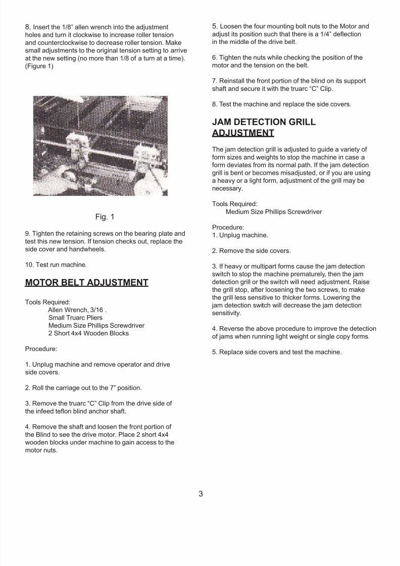
7. Loosen the screws (Two each) that retain the upper
bearing plate on each side of the feed roller or snap roller
assemblies. (Figure 1)
2
7/27/2019 FD 540 Main Man.pdf
http://slidepdf.com/reader/full/fd-540-main-manpdf 6/33
8. Insert the 1/8” allen wrench into the adjustment
holes and turn it clockwise to increase roller tension
and counterclockwise to decrease roller tension. Make
small adjustments to the original tension setting to arrive
at the new setting (no more than 1/8 of a turn at a time).
(Figure 1)
Fig. 1
9. Tighten the retaining screws on the bearing plate and
test this new tension. If tension checks out, replace the
side cover and handwheels.
10. Test run machine.
MOTOR BELT ADJUSTMENT
Tools Required:
Allen Wrench, 3/16 .
Small Truarc Pliers
Medium Size Phillips Screwdriver
2 Short 4x4 Wooden Blocks
Procedure:
1. Unplug machine and remove operator and drive
side covers.
2. Roll the carriage out to the 7” position.
3. Remove the truarc “C” Clip from the drive side of
the infeed teon blind anchor shaft.
4. Remove the shaft and loosen the front portion of
the Blind to see the drive motor. Place 2 short 4x4
wooden blocks under machine to gain access to the
motor nuts.
5. Loosen the four mounting bolt nuts to the Motor and
adjust its position such that there is a 1/4” deection
in the middle of the drive belt.
6. Tighten the nuts while checking the position of the
motor and the tension on the belt.
7. Reinstall the front portion of the blind on its support
shaft and secure it with the truarc “C” Clip.
8. Test the machine and replace the side covers.
JAM DETECTION GRILL
ADJUSTMENT
The jam detection grill is adjusted to guide a variety of
form sizes and weights to stop the machine in case a
form deviates from its normal path. If the jam detection
grill is bent or becomes misadjusted, or if you are using
a heavy or a light form, adjustment of the grill may be
necessary.
Tools Required:
Medium Size Phillips Screwdriver
Procedure:
1. Unplug machine.
2. Remove the side covers.
3. If heavy or multipart forms cause the jam detection
switch to stop the machine prematurely, then the jam
detection grill or the switch will need adjustment. Raise
the grill stop, after loosening the two screws, to make
the grill less sensitive to thicker forms. Lowering the jam detection switch will decrease the jam detection
sensitivity.
4. Reverse the above procedure to improve the detection
of jams when running light weight or single copy forms.
5. Replace side covers and test the machine.
3
7/27/2019 FD 540 Main Man.pdf
http://slidepdf.com/reader/full/fd-540-main-manpdf 7/33
STACKER DRIVE BELT
TENSION ADJUSTMENT
Tools Required:
Medium size Phillips Screwdriver
Procedure:
1. Unplug the machine.
2. Remove the operator side cover.
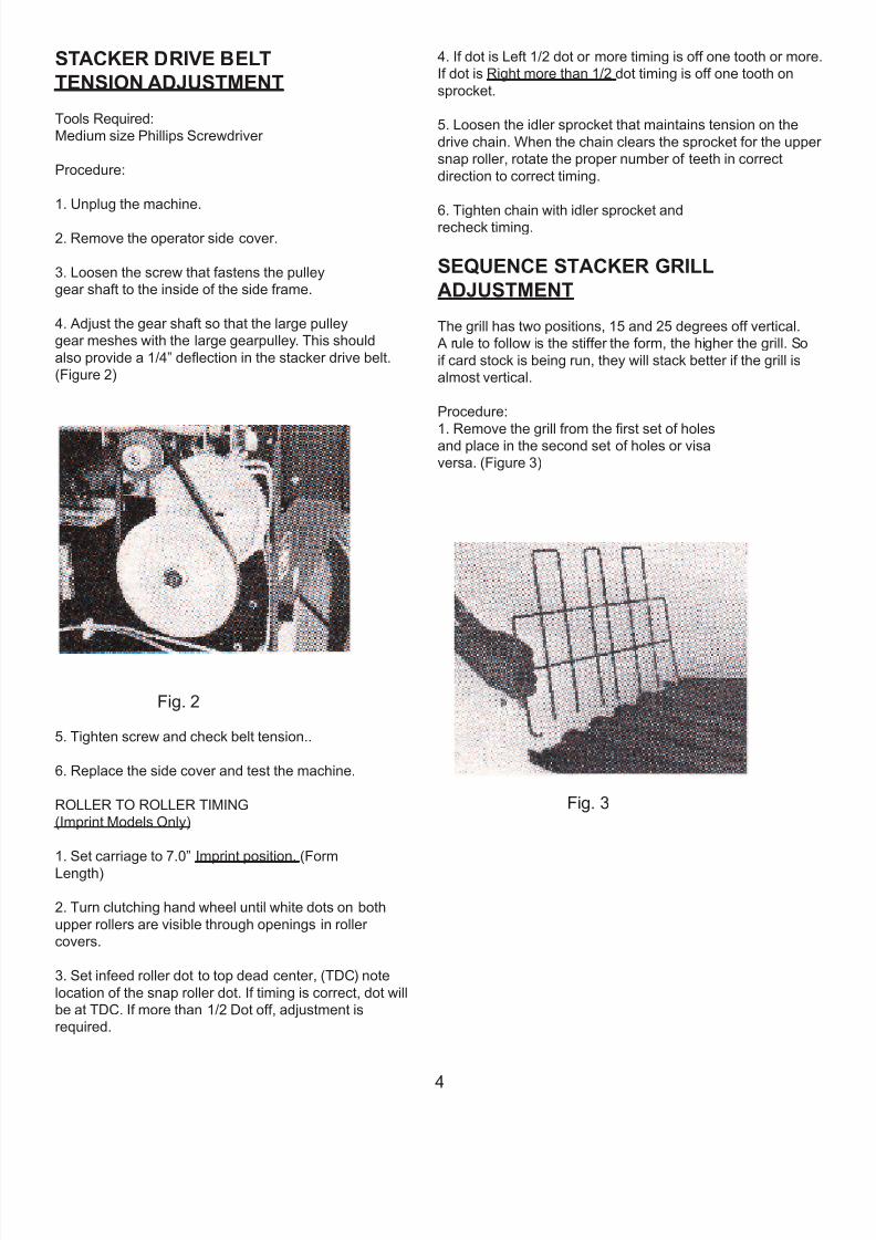
3. Loosen the screw that fastens the pulley
gear shaft to the inside of the side frame.
4. Adjust the gear shaft so that the large pulley
gear meshes with the large gearpulley. This should
also provide a 1/4” deection in the stacker drive belt.
(Figure 2)
Fig. 2
5. Tighten screw and check belt tension..
6. Replace the side cover and test the machine.
ROLLER TO ROLLER TIMING
(Imprint Models Only)
1. Set carriage to 7.0” Imprint position. (Form
Length)
2. Turn clutching hand wheel until white dots on both
upper rollers are visible through openings in roller
covers.
3. Set infeed roller dot to top dead center, (TDC) note
location of the snap roller dot. If timing is correct, dot will
be at TDC. If more than 1/2 Dot off, adjustment is
required.
4. If dot is Left 1/2 dot or more timing is off one tooth or more
If dot is Right more than 1/2 dot timing is off one tooth on
sprocket.
5. Loosen the idler sprocket that maintains tension on the
drive chain. When the chain clears the sprocket for the upper
snap roller, rotate the proper number of teeth in correct
direction to correct timing.
6. Tighten chain with idler sprocket andrecheck timing.
SEQUENCE STACKER GRILL
ADJUSTMENT
The grill has two positions, 15 and 25 degrees off vertical.
A rule to follow is the stiffer the form, the higher the grill. So
if card stock is being run, they will stack better if the grill is
almost vertical.
Procedure:
1. Remove the grill from the rst set of holesand place in the second set of holes or visa
versa. (Figure 3)
Fig. 3
4
7/27/2019 FD 540 Main Man.pdf
http://slidepdf.com/reader/full/fd-540-main-manpdf 8/33
REMOVAL &
REPLACEMENT
PROCEDURES
DRIVER CHAIN REPLACEMENT
Tools Required:Small Flat Blade Screwdriver
Medium size Phillips Head Screwdriver
Allen Wrench set
Procedure:
1. Unplug machine.
2. Remove the drive side cover.
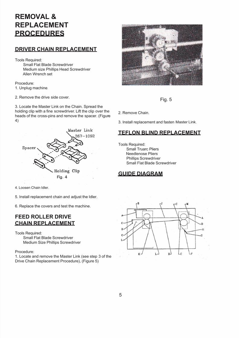
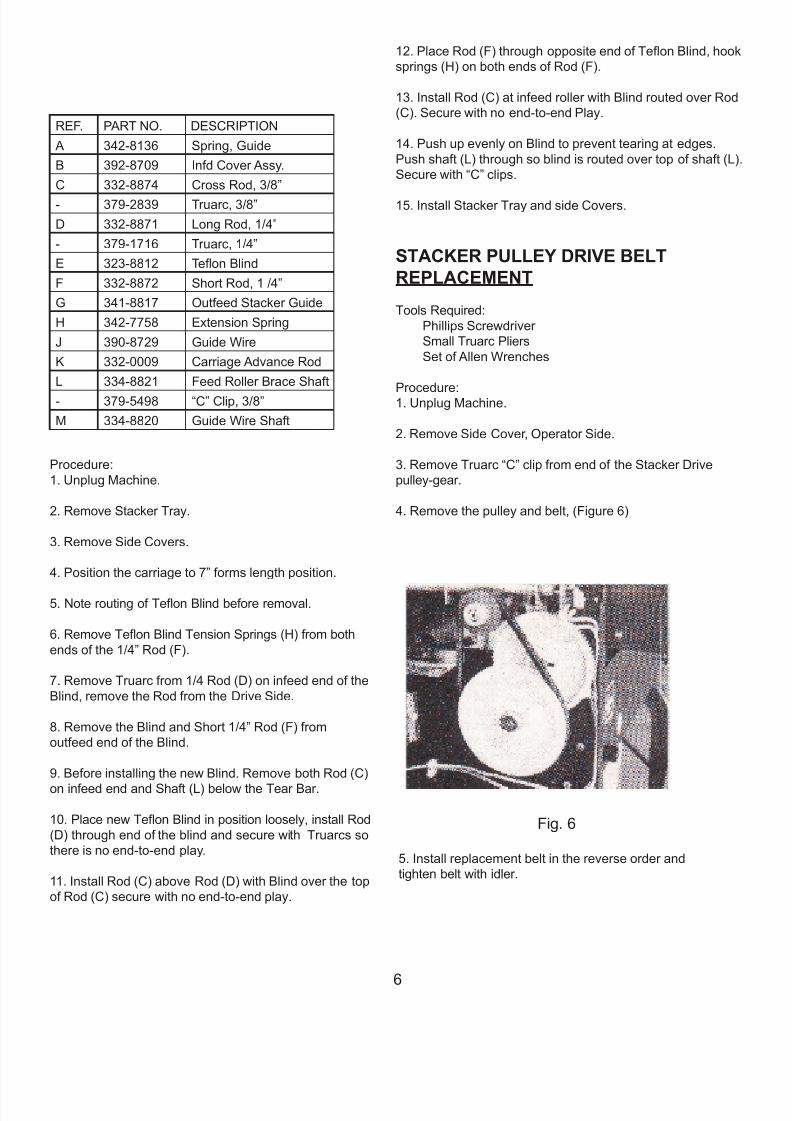
3. Locate the Master Link on the Chain. Spread the
holding clip with a ne screwdriver. Lift the clip over the
heads of the cross-pins and remove the spacer. (Figure
4)
4. Loosen Chain Idler.
5. Install replacement chain and adjust the Idler.
6. Replace the covers and test the machine.
FEED ROLLER DRIVE
CHAIN REPLACEMENT
Tools Required:
Small Flat Blade Screwdriver Medium Size Phillips Screwdriver
Procedure:
1. Locate and remove the Master Link (see step 3 of the
Drive Chain Replacement Procedure), (Figure 5)
Fig. 5
2. Remove Chain.
3. Install replacement and fasten Master Link.
TEFLON BLIND REPLACEMENT
Tools Required:
Small Truarc Pliers
Needlenose Pliers
Phillips Screwdriver
Small Flat Blade Screwdriver
GUIDE DIAGRAM
5
7/27/2019 FD 540 Main Man.pdf
http://slidepdf.com/reader/full/fd-540-main-manpdf 9/33
REF. PART NO. DESCRIPTION
A 342-8136 Spring, Guide
B 392-8709 Infd Cover Assy.
C 332-8874 Cross Rod, 3/8”
- 379-2839 Truarc, 3/8”
D 332-8871 Long Rod, 1/4”
- 379-1716 Truarc, 1/4”
E 323-8812 Teon Blind
F 332-8872 Short Rod, 1 /4”
G 341-8817 Outfeed Stacker Guide
H 342-7758 Extension Spring
J 390-8729 Guide Wire
K 332-0009 Carriage Advance Rod
L 334-8821 Feed Roller Brace Shaft
- 379-5498 “C” Clip, 3/8”
M 334-8820 Guide Wire Shaft
Procedure:
1. Unplug Machine.
2. Remove Stacker Tray.
3. Remove Side Covers.
4. Position the carriage to 7” forms length position.
5. Note routing of Teon Blind before removal.
6. Remove Teon Blind Tension Springs (H) from both
ends of the 1/4” Rod (F).
7. Remove Truarc from 1/4 Rod (D) on infeed end of the
Blind, remove the Rod from the Drive Side.
8. Remove the Blind and Short 1/4” Rod (F) from
outfeed end of the Blind.
9. Before installing the new Blind. Remove both Rod (C)
on infeed end and Shaft (L) below the Tear Bar.
10. Place new Teon Blind in position loosely, install Rod
(D) through end of the blind and secure with Truarcs so
there is no end-to-end play.
11. Install Rod (C) above Rod (D) with Blind over the top
of Rod (C) secure with no end-to-end play.
12. Place Rod (F) through opposite end of Teon Blind, hook
springs (H) on both ends of Rod (F).
13. Install Rod (C) at infeed roller with Blind routed over Rod
(C). Secure with no end-to-end Play.
14. Push up evenly on Blind to prevent tearing at edges.
Push shaft (L) through so blind is routed over top of shaft (L).
Secure with “C” clips.
15. Install Stacker Tray and side Covers.
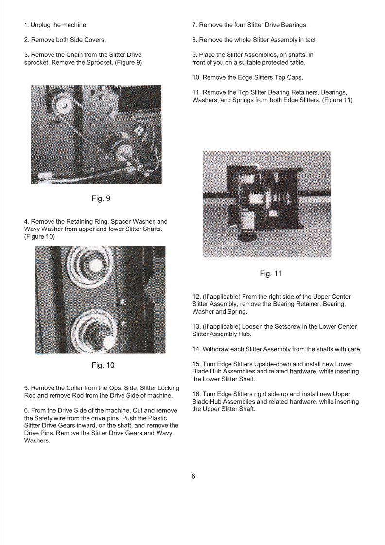
STACKER PULLEY DRIVE BELT
REPLACEMENT
Tools Required:
Phillips Screwdriver
Small Truarc Pliers
Set of Allen Wrenches
Procedure:1. Unplug Machine.
2. Remove Side Cover, Operator Side.
3. Remove Truarc “C” clip from end of the Stacker Drive
pulley-gear.
4. Remove the pulley and belt, (Figure 6)
Fig. 6
5. Install replacement belt in the reverse order and
tighten belt with idler.
6
7/27/2019 FD 540 Main Man.pdf
http://slidepdf.com/reader/full/fd-540-main-manpdf 10/33
STATIC WAND REPLACEMENT &
INSTALLATION PROCEDURE
Tools Required:
Medium Size Phillips Screwdriver
Short Phillips Screwdriver
Slip Joint Pliers
2 each 4 x 4 x 18” Wood Blocks
Procedure:
1. Unplug Machine.
2. Lift each end of machine and place a 4 X 4
wood block under ends to gain access to bottom
of machine.
3. Remove Base Plate Cover by removing the
four feet.
4. Position the Static Wand Transformer next to the Drive
Motor. (Must be done through bottom of machine or
removal of the Teon Blind is required.)
5. Place the Transformer with the power cord closest to
the outfeed end of the machine.
6. Fasten the Transformer with two screws.
(Front and Back)
NOTE: If you have a problem reaching these two
screws, remove the carriage rod from the drive side of
the machine and you can reach in under the Teon Blind.
7. Route the power cord through chassis access hole,
forward of the Speed Control.
8. Fasten the White and Black Wires. Black to pin 5 of the
terminal strip and the White to pin 6 or 7.
9. Slide the connector end of the Static Wand into the
Transformer. Fasten by turning the threaded collar
clockwise. Attach the Ground wire to the Transformer
Ground Stud.
10. Insert the Static Wand into the outfeed ngers.
(Figure 7)
11. Hold Static Wand in place with retaining brackets and
tighten Screws. The other end of Green Ground Wire
(Step 9) should be connected to the Bracket screw before
tightening.
Fig. 7
SLITTER BLADE REPLACEMENTWhen the cutting characteristics of the Slitter begins to
deteriorate it will be necessary to alternate them. Slitter
Blade Assemblies are designed to be interchangeable. By
exchanging the Upper and Lower Slitter Blade Assemblies in
each Edge Slitter Box. Double Slitter Blade life is obtained.
When both cutter edges are worn, a new set of Slitter Blade
Assemblies must be ordered and installed. (Figure 8)
Fig. 8
Tools Required:
Medium Phillips Screwdriver
Small Retaining Ring Pliers
Small Blade Screwdriver Procedure;
7
7/27/2019 FD 540 Main Man.pdf
http://slidepdf.com/reader/full/fd-540-main-manpdf 11/33
1. Unplug the machine.
2. Remove both Side Covers.
3. Remove the Chain from the Slitter Drive
sprocket. Remove the Sprocket. (Figure 9)
Fig. 9
4. Remove the Retaining Ring, Spacer Washer, and
Wavy Washer from upper and lower Slitter Shafts.
(Figure 10)
Fig. 10
5. Remove the Collar from the Ops. Side, Slitter Locking
Rod and remove Rod from the Drive Side of machine.
6. From the Drive Side of the machine, Cut and remove
the Safety wire from the drive pins. Push the Plastic
Slitter Drive Gears inward, on the shaft, and remove the
Drive Pins. Remove the Slitter Drive Gears and Wavy
Washers.
7. Remove the four Slitter Drive Bearings.
8. Remove the whole Slitter Assembly in tact.
9. Place the Slitter Assemblies, on shafts, in
front of you on a suitable protected table.
10. Remove the Edge Slitters Top Caps,
11. Remove the Top Slitter Bearing Retainers, Bearings,Washers, and Springs from both Edge Slitters. (Figure 11)
Fig. 11
12. (If applicable) From the right side of the Upper Center
Slitter Assembly, remove the Bearing Retainer, Bearing,
Washer and Spring.
13. (If applicable) Loosen the Setscrew in the Lower Center
Slitter Assembly Hub.
14. Withdraw each Slitter Assembly from the shafts with care
15. Turn Edge Slitters Upside-down and install new Lower
Blade Hub Assemblies and related hardware, while inserting
the Lower Slitter Shaft.
16. Turn Edge Slitters right side up and install new Upper
Blade Hub Assemblies and related hardware, while inserting
the Upper Slitter Shaft.
8
7/27/2019 FD 540 Main Man.pdf
http://slidepdf.com/reader/full/fd-540-main-manpdf 12/33
17. While installing the spring, Washer, Bearing Retainer
and Bearing in the Upper Blade Assembly of each Slitter
box, be sure that the Upper Slitter Assembly is sprung
against the Lower Blade Assembly.
18. Replace the Edge Slitter Top Caps.
19. Replace Slitter Assemblies and Shafts into
the Machine using the reverse of the disassembly
procedures (steps 1 - 12) to reassemble the Machine.
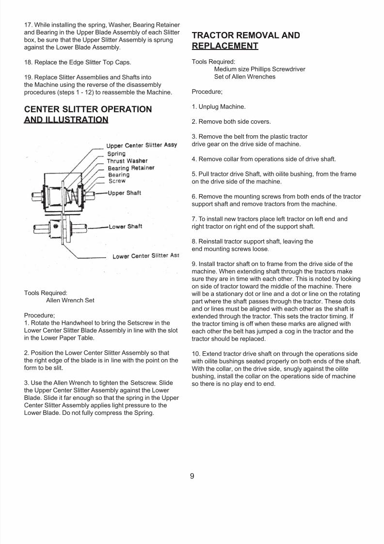
CENTER SLITTER OPERATION
AND ILLUSTRATION
Tools Required:
Allen Wrench Set
Procedure;
1. Rotate the Handwheel to bring the Setscrew in the
Lower Center Slitter Blade Assembly in line with the slot
in the Lower Paper Table.
2. Position the Lower Center Slitter Assembly so that
the right edge of the blade is in line with the point on the
form to be slit.
3. Use the Allen Wrench to tighten the Setscrew. Slidethe Upper Center Slitter Assembly against the Lower
Blade. Slide it far enough so that the spring in the Upper
Center Slitter Assembly applies light pressure to the
Lower Blade. Do not fully compress the Spring.
TRACTOR REMOVAL AND
REPLACEMENT
Tools Required:
Medium size Phillips Screwdriver
Set of Allen Wrenches
Procedure;
1. Unplug Machine.
2. Remove both side covers.
3. Remove the belt from the plastic tractor
drive gear on the drive side of machine.
4. Remove collar from operations side of drive shaft.
5. Pull tractor drive Shaft, with oilite bushing, from the frame
on the drive side of the machine.
6. Remove the mounting screws from both ends of the tracto
support shaft and remove tractors from the machine.
7. To install new tractors place left tractor on left end and
right tractor on right end of the support shaft.
8. Reinstall tractor support shaft, leaving the
end mounting screws loose.
9. Install tractor shaft on to frame from the drive side of the
machine. When extending shaft through the tractors make
sure they are in time with each other. This is noted by looking
on side of tractor toward the middle of the machine. Therewill be a stationary dot or line and a dot or line on the rotating
part where the shaft passes through the tractor. These dots
and or lines must be aligned with each other as the shaft is
extended through the tractor. This sets the tractor timing. If
the tractor timing is off when these marks are aligned with
each other the belt has jumped a cog in the tractor and the
tractor should be replaced.
10. Extend tractor drive shaft on through the operations side
with oilite bushings seated properly on both ends of the shaft
With the collar, on the drive side, snugly against the oilite
bushing, install the collar on the operations side of machine
so there is no play end to end.
9
7/27/2019 FD 540 Main Man.pdf
http://slidepdf.com/reader/full/fd-540-main-manpdf 13/33
11. Reinstall belt on pulley and slitter pulley.
NOTE; The tractor drive pulley should be free moving for
the length of the slot in the pulley. The setscrew in this
slot does not go all the way through the shaft. Shaft is
threaded part way so damage to the setscrew or shaft
will result if forced. If there is no play in the tractor drive,
signature creeping and breaking of tractor belts will
result.
12. Set edge of tractors level with infeed tray and tighten
screws on ends of support Rod.
13. Test run machine and install side covers.
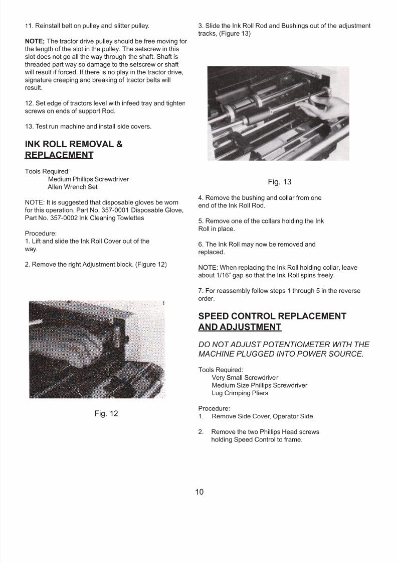
INK ROLL REMOVAL &
REPLACEMENT
Tools Required:
Medium Phillips Screwdriver
Allen Wrench Set
NOTE: It is suggested that disposable gloves be worn
for this operation. Part No. 357-0001 Disposable Glove,
Part No. 357-0002 Ink Cleaning Towlettes
Procedure:
1. Lift and slide the Ink Roll Cover out of the
way.
2. Remove the right Adjustment block. (Figure 12)
Fig. 12
3. Slide the Ink Roll Rod and Bushings out of the adjustment
tracks, (Figure 13)
Fig. 13
4. Remove the bushing and collar from oneend of the Ink Roll Rod.
5. Remove one of the collars holding the Ink
Roll in place.
6. The Ink Roll may now be removed and
replaced.
NOTE: When replacing the Ink Roll holding collar, leave
about 1/16” gap so that the Ink Roll spins freely.
7. For reassembly follow steps 1 through 5 in the reverse
order.
SPEED CONTROL REPLACEMENT
AND ADJUSTMENT
DO NOT ADJUST POTENTIOMETER WITH THE
MACHINE PLUGGED INTO POWER SOURCE.
Tools Required:
Very Small Screwdriver
Medium Size Phillips Screwdriver
Lug Crimping Pliers
Procedure:
1. Remove Side Cover, Operator Side.
2. Remove the two Phillips Head screws
holding Speed Control to frame.
10

7/27/2019 FD 540 Main Man.pdf
http://slidepdf.com/reader/full/fd-540-main-manpdf 14/33
17. While installing the spring, Washer, Bearing Retainer
and Bearing in the Upper Blade Assembly of each Slitter
box, be sure that the Upper Slitter Assembly is sprung
against the Lower Blade Assembly.
18. Replace the Edge Slitter Top Caps.
19. Replace Slitter Assemblies and Shafts into
the Machine using the reverse of the disassembly
procedures (steps 1 - 12) to reassemble the Machine.
CENTER SLITTER OPERATION
AND ILLUSTRATION
Tools Required:
Allen Wrench Set
Procedure;
1. Rotate the Handwheel to bring the Setscrew in the
Lower Center Slitter Blade Assembly in line with the slot
in the Lower Paper Table.
2. Position the Lower Center Slitter Assembly so that
the right edge of the blade is in line with the point on the
form to be slit.
3. Use the Allen Wrench to tighten the Setscrew. Slidethe Upper Center Slitter Assembly against the Lower
Blade. Slide it far enough so that the spring in the Upper
Center Slitter Assembly applies light pressure to the
Lower Blade. Do not fully compress the Spring.
TRACTOR REMOVAL AND
REPLACEMENT
Tools Required:
Medium size Phillips Screwdriver
Set of Allen Wrenches
Procedure;
1. Unplug Machine.
2. Remove both side covers.
3. Remove the belt from the plastic tractor
drive gear on the drive side of machine.
4. Remove collar from operations side of drive shaft.
5. Pull tractor drive Shaft, with oilite bushing, from the frame
on the drive side of the machine.
6. Remove the mounting screws from both ends of the tracto
support shaft and remove tractors from the machine.
7. To install new tractors place left tractor on left end and
right tractor on right end of the support shaft.
8. Reinstall tractor support shaft, leaving the
end mounting screws loose.
9. Install tractor shaft on to frame from the drive side of the
machine. When extending shaft through the tractors make
sure they are in time with each other. This is noted by looking
on side of tractor toward the middle of the machine. Therewill be a stationary dot or line and a dot or line on the rotating
part where the shaft passes through the tractor. These dots
and or lines must be aligned with each other as the shaft is
extended through the tractor. This sets the tractor timing. If
the tractor timing is off when these marks are aligned with
each other the belt has jumped a cog in the tractor and the
tractor should be replaced.
10. Extend tractor drive shaft on through the operations side
with oilite bushings seated properly on both ends of the shaft
With the collar, on the drive side, snugly against the oilite
bushing, install the collar on the operations side of machine
so there is no play end to end.
11

7/27/2019 FD 540 Main Man.pdf
http://slidepdf.com/reader/full/fd-540-main-manpdf 15/33
11. Reinstall belt on pulley and slitter pulley.
NOTE; The tractor drive pulley should be free moving for
the length of the slot in the pulley. The setscrew in this
slot does not go all the way through the shaft. Shaft is
threaded part way so damage to the setscrew or shaft
will result if forced. If there is no play in the tractor drive,
signature creeping and breaking of tractor belts will
result.
12. Set edge of tractors level with infeed tray and tighten
screws on ends of support Rod.
13. Test run machine and install side covers.
INK ROLL REMOVAL &
REPLACEMENT
Tools Required:
Medium Phillips Screwdriver
Allen Wrench Set
NOTE: It is suggested that disposable gloves be worn
for this operation. Part No. 357-0001 Disposable Glove,
Part No. 357-0002 Ink Cleaning Towlettes
Procedure:
1. Lift and slide the Ink Roll Cover out of the
way.
2. Remove the right Adjustment block. (Figure 12)
Fig. 12
3. Slide the Ink Roll Rod and Bushings out of the adjustment
tracks, (Figure 13)
Fig. 13
4. Remove the bushing and collar from oneend of the Ink Roll Rod.
5. Remove one of the collars holding the Ink
Roll in place.
6. The Ink Roll may now be removed and
replaced.
NOTE: When replacing the Ink Roll holding collar, leave
about 1/16” gap so that the Ink Roll spins freely.
7. For reassembly follow steps 1 through 5 in the reverse
order.
SPEED CONTROL REPLACEMENT
AND ADJUSTMENT
DO NOT ADJUST POTENTIOMETER WITH THE
MACHINE PLUGGED INTO POWER SOURCE.
Tools Required:
Very Small Screwdriver
Medium Size Phillips Screwdriver
Lug Crimping Pliers
Procedure:
1. Remove Side Cover, Operator Side.
2. Remove the two Phillips Head screws
holding Speed Control to frame.
12
7/27/2019 FD 540 Main Man.pdf
http://slidepdf.com/reader/full/fd-540-main-manpdf 16/33
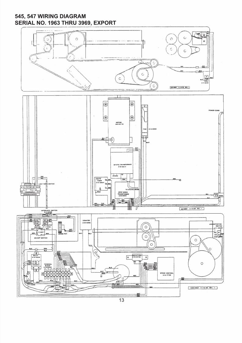
545, 547 WIRING DIAGRAM
SERIAL NO. 1963 THRU 3969, EXPORT
13
7/27/2019 FD 540 Main Man.pdf
http://slidepdf.com/reader/full/fd-540-main-manpdf 17/33
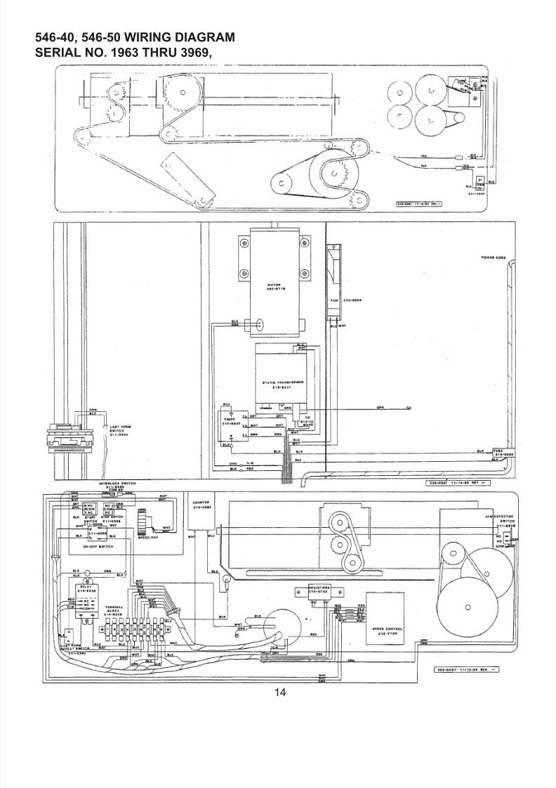
546-40, 546-50 WIRING DIAGRAM
SERIAL NO. 1963 THRU 3969,
14
7/27/2019 FD 540 Main Man.pdf
http://slidepdf.com/reader/full/fd-540-main-manpdf 18/33
544, 546 WIRING DIAGRAM
SERIAL NO. 3970 AND HIGHER
15
7/27/2019 FD 540 Main Man.pdf
http://slidepdf.com/reader/full/fd-540-main-manpdf 19/33
540-40, 540-50, 547-40, 547-50 WIRING DIAGRAM
SERIAL NO. 3970 AND HIGHER
16
7/27/2019 FD 540 Main Man.pdf
http://slidepdf.com/reader/full/fd-540-main-manpdf 20/33
544, 546 BURSTER SCHEMATIC
SERIAL NO. 1962 AND LOWER
17
7/27/2019 FD 540 Main Man.pdf
http://slidepdf.com/reader/full/fd-540-main-manpdf 21/33
BURSTER LADDER DIAGRAM
SERIAL NO. 1963 THRU 3969
18
7/27/2019 FD 540 Main Man.pdf
http://slidepdf.com/reader/full/fd-540-main-manpdf 22/33
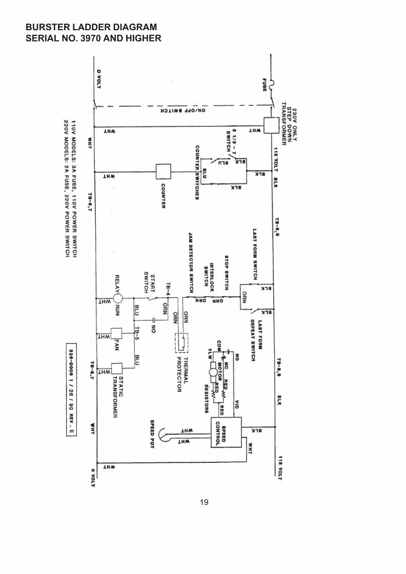
BURSTER LADDER DIAGRAM
SERIAL NO. 3970 AND HIGHER
19
7/27/2019 FD 540 Main Man.pdf
http://slidepdf.com/reader/full/fd-540-main-manpdf 23/3320
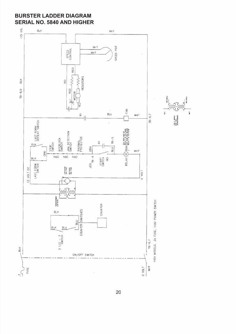
BURSTER LADDER DIAGRAM
SERIAL NO. 5840 AND HIGHER
7/27/2019 FD 540 Main Man.pdf
http://slidepdf.com/reader/full/fd-540-main-manpdf 24/33
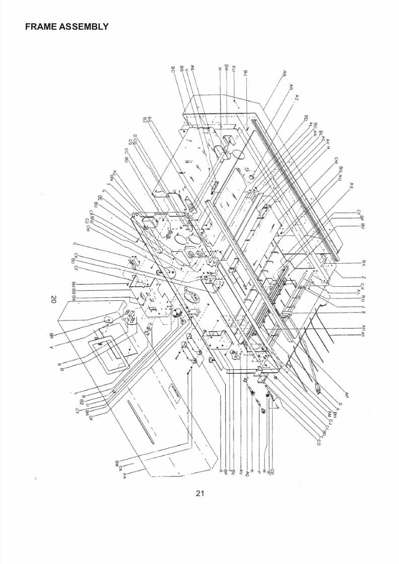
FRAME ASSEMBLY
21

7/27/2019 FD 540 Main Man.pdf
http://slidepdf.com/reader/full/fd-540-main-manpdf 25/33
FRAME ASSEMBLYREF. PART NO. DESCRIPTION REF. PART NO. DESCRIPTION REF. PART NO. DESCRIPTION
A 392-8750 Power Cord Assy.
- 310-5052 Power Cord 11 5V A-R 334-8568 Safety Cover Guide, Dr C-L 379-2840 1/2” Retaining Ring
B 311-0008 Push Button Switch A-S 334-8924 Infeed Brush Bar C-M 392-8709 Infeed Cover Assembly
C 311-0009 On-Off Switch A-T 341-8556 Jam Detection Grill C-R 334-8820 Shaft Guide Wire
D 311-8838 Switch Interlock A-U 341-8816 Blind Finger Guide C-S 312-8837 Timer, #1963 - #3969
E 311-8839 Jam Detection Switch A-V 341-8817 Outfeed Guide Stacker C-T 319-0030 Speed Potentiometer
F 312-7700 Speed Control A-X 342-7758 Module Lock Spring - 377-5467 Wafer Washer
G 314-8335 9 Term Terminal Board A-Y 342-8163 Guide Strap Spring C-U 382-0006 .50 Tinnerman Clip
H 314-8854 #4 Ring Connect A-Z 357-0005 5/8” Hole Plug
J 314-8855 1/4 Ring Connector B-A 360-0053 Speed Pot. Mt. Brkt. NOT SHOWN:
K 315-0003 Cap, Color Code-Green B-B 360-0054 Control Panel
L 315-0004 Cap, Color-Red - 325-0054 Control Panel Inlay X- 392-0033 Cooling Fan Assembly
M 315-5096 Tie Mount B-C 360-0083 Infeed Table X- 313-0004 Cooling Fan.
N 319-5330 Fuse Holder B-D 360-0084 Extended Table X- 341-0006 Fan Guard
P 319-0006 Fuse 3 Amp Slo Blow - 360-8894 Short Table (2546-40) X- 392-8316 5 KV Static Trans. Assy.
R 319-5762 Resistor Ohmite F403 B-E 360-4092 Hole Cover Plate X- 316-8317 Static Transformer
S 319-8318 Static Bar B-F 360-8315 Static Wand Ret. Brkt. X- 378-0004 #10 Kepnut (10-32)
T 319-8336 Relay Deltrol B-G 360-8379 Mt. Bracket Interlock X- 314-5084 #6 Ring Connect
U 320-0008 Thumb Wheel B-H 360-8456 Static Wand Bracket X- 325-0057 Close Cover Decal
V 320-0009 Barrier Bezel B-J 375-0004 6-32 x 1/4 Screw X- 360-0133 Bottom Cover M2540
W 320-6348 Paper Guide B-K 360-8805 Jam Detection Stop
X 320-6371 Spacer Bracket B-L 360-8822 Infeed Cover Plate
Y 320-8890 Infeed Brush B-M 362-4089 Extended Frame, Dr
Z 321-8554 Safety Cover B-N 362-4090 Extended Frame, Ops
A-A 390-0393 Side Cover Assy., Ops B-P 372-6544 Non Swivel Adj. Glide
- 390-0356 Cover Assy. w/counter B-R 372-9587 1/8” Push-On Clips
- 322-0001 Side Cover, Ops B-S 373-2842 6-32 x 5/8 Screw
- 322-0003 Cover Ops w/Counter B -T 373-5826 3-48 x 3/4 Screw
- 320-9586 Control Panel Bezel B-U 373-5869 6-32 int.”Sems” Screw
- 325-5131 TAB Logo B-V 373-5893 6-32 x 3/8 int.”Sems”
- 325-5146 Warning Decal B-W 373-6550 10-24 x 1 1/4 Screw
- 372-9587 1/8”Push-on clips B-X 375-6625 6-32 x 3/8 Screw
A-B 390-0394 Cover Assy., Drive Sside B-Y 375-6537 3-48 x 5/8 screw
- 322-0002 Side Cover, Drive Side B-Z 375-6588 6-32 x 5/16 Screw
A-C 323-8812 Teon Blind C-A 377-2809 # 10 Ext. Tooth Washer
A-G 328-8770 Carriage Guide Rod C-B 377-5855 #3 Int. Star Washer
A-H 390-8729 Guide Wire Assy. C-C 377-5481 Curved Spring Washer
A-J 330-5730 Collar 3/8” C-D 377-2811 #6 SAE Washer
- 376-2804 1/4-28 x 1/4, Setscrew C-F 378-0071 6-32 Hex Nut
A-L 332-8871 1/4” Cross Rod, Long C-G 378-5836 3-48 Hex Nut
A-M 332-8872 1/4” Cross Rod, Short C-H 378-6549 1/4 x 20 Kepnut Nut
A-N 332-8874 3/8” Cross Rod C-J 379-1716 1/4” Retaining Ring
A-P 334-8567 Safety Cover Guide, Op C-K 379-2839 3/8” Retaining Ring
7/27/2019 FD 540 Main Man.pdf
http://slidepdf.com/reader/full/fd-540-main-manpdf 26/33
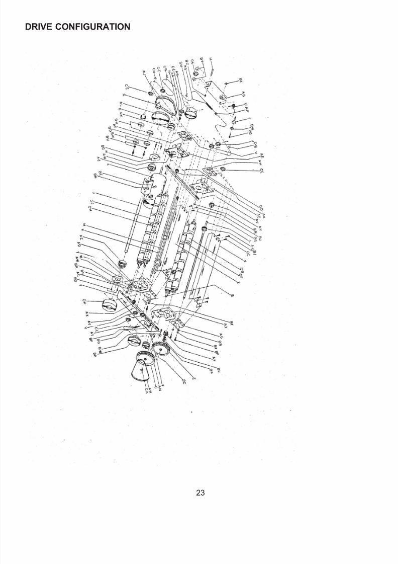
DRIVE CONFIGURATION
23

7/27/2019 FD 540 Main Man.pdf
http://slidepdf.com/reader/full/fd-540-main-manpdf 27/33
DRIVE CONFIGURATIONREF. PART NO. DESCRIPTION PART NO. DESCRIPTION REF. PART NO. DESCRIPTION
A 392-8710 Motor Assy. A-G 362-8786 Up Snap RlIr. Plt.,Ops. B-W 377-5290 #10 Fender Washer
313-8835 1/6 HP Motor A-H 362-8788 Up Snap Rllr PIt.,Dr. B-X 377-5481 Curved Spring Washer
315-8533 Motor Brush A-J 365-1072 Synchronous Belt B-Z 378-6549 1/4-20 Kep Nut
C 320-5087 Small Gear Pulley A-K 365-8780 18T Plly, to Ser. #4219 C-A 379-2839 3/8” Retaining Ring
E 328-8783 Stacker Drive Gear 365-0005 22T Gear Bit Plly -40-50 C-B 379-5498 Truarc #5103-37
F 330-5394 Idler Stud and all machines Ser. # 4220 up) C-C 381-5784 Spring Pin, 1/8 x 5/8
G 330-8789 Idler Stud 376-0078 10-32 x 1/4 Setscrew C-D 381-6563 1/8” Dia. Drive Rivet
J 332-0008 Extended Drive Shaft A-L 365-8784 60-23 Combo Pulley C-E 390-0001 Idler Sprocket Assy.
K 332-0009 Carriage Advance Shaft - 376-2807 1/4-20 x 1/4 Setscrew C-F 390-8506 Lower Snap Roller, Nit
L 332-8804 Stacker Drive Shaft A-M 366-0683 Motor Belt 390-8539 Lower Snap Roller,Poly
M 390-4109 Tear Bar Assembly A-N 366-3171 Fork Clutch Pulley C-G 390-8507 Upper Snap Roller,Nit.
334-8679 Tear Bar 376-0075 10-24 x 3/16 Setscrew - 390-8538 Upper Snap Roller,Poly
320-6238 Tear Point A-P 367-1092 Master Link C-H 390-8508 Upper Feed Roller,Nit.
342-6345 Spring Clip 367-2953 Half Link 390-8536 Upper Feed Roller,Poly
342-8180 Tear Point Bar Spring A-R 367-8778 24T Sprkt, to Ser.#4219 C-J 390-8509 Lower Feed Roller,Nit.
N 342-3121 Roller Shaft Spring 376-0003 1/4-20 x 3/8 Setscrew 390-8537 Lower Feed Roller,Poly
S 342-8883 Bearing Spring, Upper 367-4087 32T Spkt,Ser.#4220 Up C-K 390-8575 Clutch Handwhl Assy.
T 342-8884 Bearing Spring, Lower A-S 367-8781 Mn Dr Ch,to Ser.#4219 - 376-0085 1/4-28 x 1/2 Setscrew
V 343-8775 16T Drive Sprocket 367-4088 Main Drive Chain
367-4087 32T Sprocket (-40,-50) -40,-50,& Ser.#4220 up ASSEMBLIES
and all machines Ser.# 4220 up A -T 367-8782 Feed Roller Chain
376-2807 1/4-20 x 1/4 Setscrew A-U 368-8691 Stacker Gear X- 390-8716 Feed Roller Carr. Assy.
W 360-5314 Bearing Retainer 1.75 381-8693 Groove Pin X- 390-8723 I’d Roller Pit. Assy.,Ops
X 360-6663 Snap Roller Cover AN 368-8771 Carriage Adj. Rack X- 390-8724 Fd Roller Pit. Assy.,Dr.
Y 360-8759 Guard Plate A-W 368-8772 Rack Carr. Lock Seg. X- 390-8726 Snp RIr Car. Pit AssyDr
Z 360-8828 Feed Roller Cover A-X 368-8774 15T Spur Gear X- 390-8727 Snp RIr Car. Pit Assy,0p
A-A 360-8878 Bushing A-Y 370-2824 3/8” Sheilded Bearing
A-B 390-8689 Tension Arm Assembly A-Z 370-5992 Ball Bearing NOT
- 360-8985 Tensioner Arm B-A 390-0106 Form Length Knob
- 377-5481 Curved Spring Washer 376-6559 10-32 x 1/2 Setscrew X- 360-0258 Side Frame Idler Brace
- 330-8983 Tension Stud B-B 373-5745 10-24 x 3/8 Screw X- 360-8760 Wire Guard, Ops Side
- 377-6626 7/16” Nylon Washer B-C 373-5869 6-32 Int. “sems” Screw
- 390-0001 Idler Sprocket B-D 373-5893 6-32 x 3/8 Int. “sems”
- 378-6549 1/4-20 Kep Nut B-E 373-2816 1/4-20 x 1/2 Bolt
- 342-8986 Torsion Spring B-F 374-0040 1/4-20 x 1/2 Screw
- 330-5394 Stud B-G 374-0047 10-24 x 1/2 Screw
- 377-5290 # 10 Fender Washer B-H 375-0004 6-32 x 1/4 Screw
- 374-0047 10-24 x 1/2 Screw B-J 375-6538 10-32 x 1/2 button HD
A-C 362-8766 Up Feed RIlr Plt., Ops B-N 377-1813 1/4” Washer
A-D 362-0011 Pit. Rt. RlIr, #2313-up B-R 377-1086 #6 Split-lock Washer
362-8767 Pit. Rt. Rl1r, #2312-Dn B-S 377-1813 Washer 1/4”
A-E 362-0010 Pit. Lft. RIIr, #2313-up B -T 377-2611 1/4” Split-lock Washer
362-8768 Pit. Lft. RIIr, #231 2-Dn B-U 377-2809 # 10 Ext. Tooth Washer
A-F 362-8769 Up Feed Rllr Plate,Dr. B-V 377-4077 3/8 Flat Washer
7/27/2019 FD 540 Main Man.pdf
http://slidepdf.com/reader/full/fd-540-main-manpdf 28/33
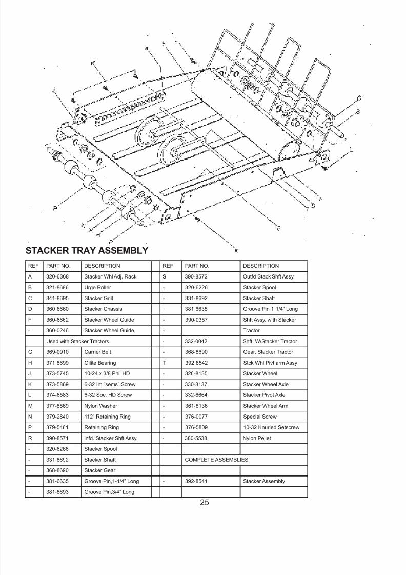
STACKER TRAY ASSEMBLY
REF PART NO. DESCRIPTION REF PART NO. DESCRIPTION
A 320-6368 Stacker Whl Adj. Rack S 390-8572 Outfd Stack Shft Assy.
B 321-8696 Urge Roller - 320-6226 Stacker Spool
C 341-8695 Stacker Grill - 331-8692 Stacker Shaft
D 360-6660 Stacker Chassis - 381-6635 Groove Pin 1-1/4” Long
F 360-6662 Stacker Wheel Guide - 390-0357 Shft Assy. with Stacker
- 360-0246 Stacker Wheel Guide, - Tractor
Used with Stacker Tractors - 332-0042 Shft, W/Stacker Tractor
G 369-0910 Carrier Belt - 368-8690 Gear, Stacker Tractor
H 371-8699 Oilite Bearing T 392-8542 Stck Whl Pivt arm Assy
J 373-5745 10-24 x 3/8 Phil HD - 320-8135 Stacker Wheel
K 373-5869 6-32 Int.”sems” Screw - 330-8137 Stacker Wheel Axle
L 374-6583 6-32 Soc. HD Screw - 332-6664 Stacker Pivot Axle
M 377-8569 Nylon Washer - 361-8136 Stacker Wheel Arm
N 379-2840 112” Retaining Ring - 376-0077 Special Screw
P 379-5461 Retaining Ring - 376-5809 10-32 Knurled Setscrew
R 390-8571 lnfd. Stacker Shft Assy. - 380-5538 Nylon Pellet
- 320-6266 Stacker Spool
- 331-8692 Stacker Shaft COMPLETE ASSEMBLIES
- 368-8690 Stacker Gear
- 381-6635 Groove Pin,1-1/4” Long - 392-8541 Stacker Assembly
- 381-8693 Groove Pin,3/4” Long
25
7/27/2019 FD 540 Main Man.pdf
http://slidepdf.com/reader/full/fd-540-main-manpdf 29/33
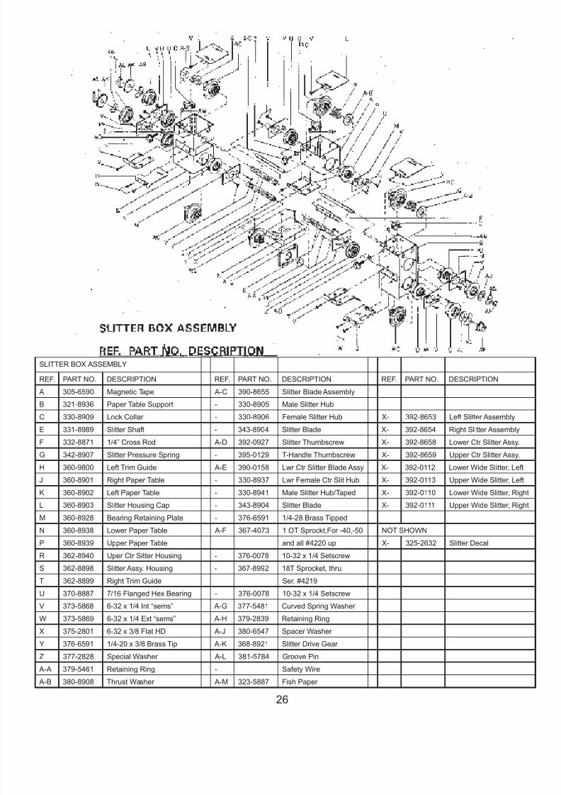
SLITTER BOX ASSEMBLY
REF. PART NO. DESCRIPTION REF. PART NO. DESCRIPTION REF. PART NO. DESCRIPTION
A 305-6590 Magnetic Tape A-C 390-8655 Slitter Blade Assembly
B 321-8936 Paper Table Support - 330-8905 Male Slitter Hub
C 330-8909 Lock Collar - 330-8906 Female Slitter Hub X- 392-8653 Left Slitter Assembly
E 331-8989 Slitter Shaft - 343-8904 Slitter Blade X- 392-8654 Right Slitter Assembly
F 332-8871 1/4” Cross Rod A-D 392-0927 Slitter Thumbscrew X- 392-8658 Lower Ctr Slitter Assy.
G 342-8907 Slitter Pressure Spring - 395-0129 T-Handle Thumbscrew X- 392-8659 Upper Ctr Slitter Assy.
H 360-9800 Left Trim Guide A-E 390-0158 Lwr Ctr Slitter Blade Assy X- 392-0112 Lower Wide Slitter, Left
J 360-8901 Right Paper Table - 330-8937 Lwr Female Ctr Slit Hub X- 392-0113 Upper Wide Slitter, Left
K 360-8902 Left Paper Table - 330-8941 Male Slitter Hub/Taped X- 392-0110 Lower Wide Slitter, Righ
L 360-8903 Slitter Housing Cap - 343-8904 Slitter Blade X- 392-0111 Upper Wide Slitter, Righ
M 360-8928 Bearing Retaining Plate - 376-6591 1/4-28 Brass Tipped
N 360-8938 Lower Paper Table A-F 367-4073 1 OT Sprockt,For -40,-50 NOT SHOWN
P 360-8939 Upper Paper Table and all #4220 up X- 325-2632 Slitter Decal
R 362-8940 Uper Ctr Sitter Housing - 376-0078 10-32 x 1/4 SetscrewS 362-8898 Slitter Assy. Housing - 367-8992 18T Sprocket, thru
T 362-8899 Right Trim Guide Ser. #4219
U 370-8887 7/16 Flanged Hex Bearing - 376-0078 10-32 x 1/4 Setscrew
V 373-5868 6-32 x 1/4 Int “sems” A-G 377-5481 Curved Spring Washer
W 373-5869 6-32 x 1/4 Ext “sems” A-H 379-2839 Retaining Ring
X 375-2801 6-32 x 3/8 Flat HD A-J 380-6547 Spacer Washer
Y 376-6591 1/4-20 x 3/8 Brass Tip A-K 368-8921 Slitter Drive Gear
Z 377-2828 Special Washer A-L 381-5784 Groove Pin
A-A 379-5461 Retaining Ring - Safety Wire
A-B 380-8908 Thrust Washer A-M 323-5887 Fish Paper
26
7/27/2019 FD 540 Main Man.pdf
http://slidepdf.com/reader/full/fd-540-main-manpdf 30/33
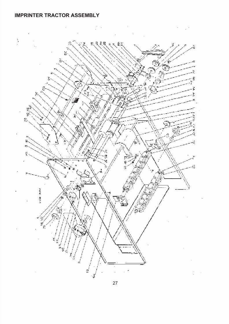
IMPRINTER TRACTOR ASSEMBLY
27
7/27/2019 FD 540 Main Man.pdf
http://slidepdf.com/reader/full/fd-540-main-manpdf 31/33
STA19WR-TRACTOR FINGERS ASSEMBLYREF. PART NO. DESCRIPTION
A 360-0215 Stacker Tractor
B 371-5777 Bronze Bushing
C 330-5715 1/4” Collar
376-0078 10-32 x 1/4 Setscrew
D 365-0023 14T Pulley, 1 /4” Bore
376-2805 8-32 x 3/16 Setscrew
E 365-8118 140XL037 Belt
F 392-0055 14T Idler Pulley Assy.
365-0003 14T Drive Pulley
371-5808 1/4” ID Bronze Bushing
G 379-1716 1/4” Retaining Ring
H 332-0028 Tractor Idler Rod
I 371-0014 1/4” ID Flange Bushing
K 371-0013 3/8” ID Flange Bushing
L 371-8699 1/2” ID Flange Bushing
M 377-8569 Washer
N 379-2840 1/2” Retaining Ring
P 390-0357 Shaft Assy. w/Stacker
332-0042 Stacker Shaft
368-8690 Stacker Gear
320-6226 Stacker Spool
381-6635 Groove Pin 1 1/4”
381-8693 Groove Pin 3/4”
Q 332-0029 3/8” Stkr Tractor Dr Rod
R 365-0002 20T Gear Belt Pulley376-0069 8-32 x 1/4 Setscrew
S 360-0235 Stkr Tractor Dr Finger
U 360-0246 Stkr Wheel Guide29
V 368-8691 Stacker Gear
X 390-0099 3/4” Thumbscrew Assy
Y 332-0041 Finger Drive Shaft
AA 381-0013 Magnets
373-5482 6-32 x 1/2 Screw
378-9500 #6 Kepnut
COMPLETE ASSEMBLY
X- 390-0181 Stkr Tractor Finger Assy
28

7/27/2019 FD 540 Main Man.pdf
http://slidepdf.com/reader/full/fd-540-main-manpdf 32/33
DecalsREF. PART NO. DESCRIPTION
X- 325-0066 3 Amp, Fast Blow
X- 325-5078 Electrical Warning
X- 325-0001 7” Timing
X- 325-0002 Counter Mode
X- 325-0003 Last Form Defeat
X- 325-0057 CLOSE
X- 325-5146 Warning
X- 325-5131 Logo
X- 325-5940 Fuse Warning
X- 325-0041 Maintenance Warning
Mini Table
REF. PART NO. DESCRIPTION
X- 372-0008 Castors
29

7/27/2019 FD 540 Main Man.pdf
http://slidepdf.com/reader/full/fd-540-main-manpdf 33/33