fcc part 90 test and measurement report
TRANSCRIPT

Note: This test report is prepared for the customer shown above and for the device described herein. It may not be duplicated or used in part without prior written consent from Bay Area Compliance Laboratories Corp. This report must not be used by the customer to claim product certification, approval, or endorsement by NVLAP*, NIST, or any agency of the Federal Government. * This report may contain data that are not covered by the NVLAP accreditation and are marked with an asterisk “*”
FCC PART 90 TEST AND MEASUREMENT REPORT
For
Pacific Crest Corporation
510 Deguigne Drive, Sunnyvale, CA 94085, USA
FCC ID: KEAADLP
Report Type:
Original Report
Product Type:
UHF Transceiver Module
Test Engineers: Jerry Huang
Report Number: R1008242-90
Report Date: 2010-12-17
Reviewed By: Victor Zhang RF Lead
Prepared By: (84)
Bay Area Compliance Laboratories Corp. 1274 Anvilwood Avenue, Sunnyvale, CA 94089, USA Tel: (408) 732-9162 Fax: (408) 732-9164
Pacific Crest Corporation FCC ID: KEAADLP
Report Number: R1008242-90 Page 2 of 92 FCC Part 90 Test Report
Table of Contents
1 GENERAL DESCRIPTION ......................................................................................................................................6
1.1 PRODUCT DESCRIPTION FOR EQUIPMENT UNDER TEST (EUT).............................................................................6 1.2 TECHNICAL SUMMARY ..........................................................................................................................................6 1.3 MECHANICAL DESCRIPTION ..................................................................................................................................6 1.4 EUT PHOTOS .........................................................................................................................................................7 1.5 OBJECTIVE .............................................................................................................................................................7 1.6 RELATED SUBMITTAL(S)/GRANT(S) ......................................................................................................................7 1.7 TEST METHODOLOGY ............................................................................................................................................7 1.8 TEST FACILITY .......................................................................................................................................................8
2 SYSTEM TEST CONFIGURATION .......................................................................................................................9
2.1 JUSTIFICATION .......................................................................................................................................................9 2.2 EUT EXERCISE SOFTWARE....................................................................................................................................9 2.3 EQUIPMENT MODIFICATIONS .................................................................................................................................9 2.4 LOCAL SUPPORT EQUIPMENT ................................................................................................................................9 2.5 EUT INTERNAL CONFIGURATION DETAILS............................................................................................................9 2.6 INTERFACE PORTS AND CABLING ..........................................................................................................................9 2.7 POWER SUPPLY INFORMATION.............................................................................................................................10
3 SUMMARY OF TEST RESULTS ........................................................................................................................... 11
4 FCC §2.1091 – RF EXPOSURE INFORMATION................................................................................................12
4.1 APPLICABLE STANDARDS ....................................................................................................................................12 4.2 MPE PREDICTION ................................................................................................................................................12 4.3 RESULT ................................................................................................................................................................13
5 FCC §2.1046 & §90.205 – RF OUTPUT POWER.................................................................................................14
5.1 APPLICABLE STANDARDS ....................................................................................................................................14 5.2 TEST PROCEDURE ................................................................................................................................................14 5.3 TEST EQUIPMENT LIST AND DETAILS ..................................................................................................................14 5.4 TEST ENVIRONMENT CONDITIONS ......................................................................................................................14 5.5 TEST RESULTS......................................................................................................................................................15
6 FCC §2.1047 & §90.207 - MODULATION CHARACTERISTIC ......................................................................16
6.1 APPLICABLE STANDARD ......................................................................................................................................16 6.2 TEST PROCEDURE ................................................................................................................................................16 6.3 TEST RESULTS......................................................................................................................................................16
7 FCC §2.1049, §90.209 & §90210 – OCCUPIED BANDWIDTH AND EMISSION MASK .............................17
7.1 APPLICABLE STANDARD ......................................................................................................................................17 7.2 TEST PROCEDURE ................................................................................................................................................18 7.3 TEST EQUIPMENT LIST AND DETAILS ..................................................................................................................18

Pacific Crest Corporation FCC ID: KEAADLP
Report Number: R1008242-90 Page 3 of 92 FCC Part 90 Test Report
7.4 TEST ENVIRONMENT CONDITIONS ......................................................................................................................18 7.5 TEST RESULTS......................................................................................................................................................18
8 FCC §2.1051 & §90.210 – SPURIOUS EMISSIONS AT ANTENNA TERMINALS........................................31
8.1 APPLICABLE STANDARD ......................................................................................................................................31 8.2 TEST PROCEDURE ................................................................................................................................................31 8.3 TEST EQUIPMENT LIST AND DETAILS ..................................................................................................................31 8.4 TEST ENVIRONMENT CONDITIONS ......................................................................................................................31 8.5 TEST RESULTS......................................................................................................................................................32
9 FCC §2.1053 & §90.210 - RADIATED SPURIOUS EMISSIONS ......................................................................58
9.1 APPLICABLE STANDARD ......................................................................................................................................58 9.2 TEST PROCEDURE ................................................................................................................................................58 9.3 TEST EQUIPMENT LIST AND DETAILS ..................................................................................................................59 9.4 TEST SETUP..........................................................................................................................................................59 9.5 TEST ENVIRONMENTAL CONDITIONS ..................................................................................................................60 9.6 TEST RESULT .......................................................................................................................................................60
10 FCC §2.1055 & §90.213- FREQUENCY STABILITY..........................................................................................64
10.1 APPLICABLE STANDARD ......................................................................................................................................64 10.2 TEST PROCEDURE ................................................................................................................................................64 10.3 TEST EQUIPMENT LIST AND DETAILS ..................................................................................................................64 10.4 TEST ENVIRONMENT CONDITIONS ......................................................................................................................64 10.5 TEST RESULTS......................................................................................................................................................65
11 FCC §90.214 – TRANSIENT FREQUENCY BEHAVIOR ..................................................................................68
11.1 STANDARD APPLICABLE ......................................................................................................................................68 11.2 TEST METHOD .....................................................................................................................................................68 11.3 TEST EQUIPMENT LIST AND DETAILS ..................................................................................................................68 11.4 TEST ENVIRONMENT CONDITIONS ......................................................................................................................68 11.5 TEST RESULTS......................................................................................................................................................69
12 EXHIBIT A - FCC LABEL INFORMATION .......................................................................................................77
12.1 FCC LABEL REQUIREMENTS ...............................................................................................................................77 12.2 FCC ID LABEL CONTENTS ..................................................................................................................................77 12.3 FCC ID LABEL LOCATION ON EUT.....................................................................................................................78
13 EXHIBIT B – TEST SETUP PHOTOGRAPHS....................................................................................................79
13.1 TRANSMITTER SPURIOUS EMISSIONS – FRONT VIEW (BELOW 1 GHZ)...............................................................79 13.2 TRANSMITTER SPURIOUS EMISSIONS – REAR VIEW (BELOW 1 GHZ).................................................................79 13.3 TRANSMITTER SPURIOUS EMISSIONS – FRONT VIEW (ABOVE 1 GHZ) ...............................................................80 13.4 TRANSMITTER SPURIOUS EMISSIONS – REAR VIEW (ABOVE 1 GHZ).................................................................80
14 EXHIBIT C - EUT PHOTOGRAPHS ....................................................................................................................81
14.1 EUT-TOP VIEW (ADLP)......................................................................................................................................81 14.2 EUT- BOTTOM VIEW (ADLP) .............................................................................................................................81 14.3 EUT- TOP VIEW (TDL 450H) ..............................................................................................................................82 14.4 EUT-BOTTOM VIEW (TDL 450H) .......................................................................................................................82

Pacific Crest Corporation FCC ID: KEAADLP
Report Number: R1008242-90 Page 4 of 92 FCC Part 90 Test Report
14.5 EUT–ANTENNA PORT VIEW (ADLP)..................................................................................................................83 14.6 EUT–ANTENNA PORT VIEW (TDL 450H)...........................................................................................................83 14.7 EUT–CONTROL PORT VIEW (ADLP) ..................................................................................................................84 14.8 EUT–CONTROL PORT VIEW (TDL 450H) ...........................................................................................................84 14.9 EUT – COVER OFF VIEW (ADL VANTAGE PRO(ADLP)).....................................................................................85 14.10 EUT – RF PCB1 ASSEMBLY TOP VIEW (ADL VANTAGE PRO (ADLP)) .............................................................85 14.11 EUT – RF PCB1 ASSEMBLY BOTTOM VIEW (ADL VANTAGE PRO(ADLP)) ......................................................86 14.12 EUT – RF PCB2 ASSEMBLY TOP VIEW (ADL VANTAGE PRO(ADLP)) ..............................................................86 14.13 EUT – RF PCB2 ASSEMBLY BOTTOM VIEW (ADL VANTAGE PRO(ADLP)) ......................................................87 14.14 EUT – COVER OFF VIEW (TDL 450H) ................................................................................................................87 14.15 EUT – RF PCB1 ASSEMBLY TOP VIEW (TDL 450H)..........................................................................................88 14.16 EUT – RF PCB1 ASSEMBLY BOTTOM VIEW .......................................................................................................88 14.17 EUT – RF PCB2 ASSEMBLY BOTTOM VIEW .......................................................................................................89 14.18 EUT – RF PCB2 ASSEMBLY TOP VIEW...............................................................................................................89 14.19 EUT – DISPLAY BOARD ASSEMBLY TOP VIEW....................................................................................................90 14.20 EUT – DISPLAY BOARD ASSEMBLY BOTTOM VIEW............................................................................................90 14.21 EUT – OPEN CHASSIS VIEW................................................................................................................................91
15 EXHIBIT D – DECLARATION OF SIMILARITY .............................................................................................92

Pacific Crest Corporation FCC ID: KEAADLP
Report Number: R1008242-90 Page 5 of 92 FCC Part 90 Test Report
DOCUMENT REVISION HISTORY
Revision Number Report Number Description of Revision Date of Revision
0 R1008242-90 Original Report 2010-11-23
1 R1008242-90 Added 390-430 test data 2010-12-17

Pacific Crest Corporation FCC ID: KEAADLP
Report Number: R1008242-90 Page 6 of 92 FCC Part 90 Test Report
1 General Description
1.1 Product Description for Equipment Under Test (EUT) This test and measurement report has been prepared on behalf of Pacific Crest Corporation and their product, models: ADLP-1 & ADLP-2, FCC ID: KEAADLP or the EUT as referred to in the rest of this report. The EUT is a transceiver designed to provide data communication using UHF radio frequencies, operating frequency Band: 390~ 430 MHz, 430~473 MHz. The EUT supports GMSK/4FSK modulation schemes. Based on the declaration of similarity (Appendix I), the following models are similar.
Models Covered by the Declaration of Similarity
ADL Vantage Pro (ADLP)
TDL 450H
1.2 Technical Summary No. of Units: Two Equipment Series Number (Model Number): ADLP-1 & ADLP-2 Power Characteristics: Variable output power form 2 to 35 Watts Channel Spacing: 25 kHz & 12.5 kHz, Unit No.1: Frequency Characteristics: 390 to 430 MHz, Test Frequency: 390.05 MHz, 410 MHz, 429.95 MHz Serial Number: 211505 & 10370002 Temperature Range:-30° to 60° Unit No.2: Frequency Characteristics: 430 to 473 MHz, Test Frequency: 430.05 MHz, 450 MHz, 472.95 MHz Serial Number: 211598 & 10370005 Temperature Range:-30° to 60° DC power section: Incoming DC voltage is regulated with a switching DC to DC converter. The externally supplied DC voltage may vary from 9V~30V, If the external voltage is outside this range, it will not be allowed to operate. In following TX & RX testing, we use 12VDC as our external supplied DC voltage. 1.3 Mechanical Description The EUT measures approximately 150 mm (L) x 103 mm (W) x 85 mm (H) and weighs 1970.5 g. The test data gathered are from production sample, 390-430MHz: 211505 & 10370002, 430-473MHz: 211598 & 10370005 provided by the manufacturer.
Pacific Crest Corporation FCC ID: KEAADLP
Report Number: R1008242-90 Page 7 of 92 FCC Part 90 Test Report
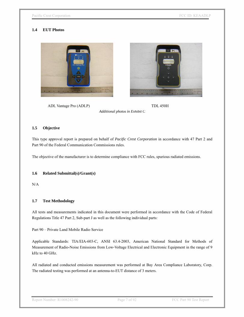
1.4 EUT Photos
Additional photos in Exhibit C 1.5 Objective This type approval report is prepared on behalf of Pacific Crest Corporation in accordance with 47 Part 2 and Part 90 of the Federal Communication Commissions rules. The objective of the manufacturer is to determine compliance with FCC rules, spurious radiated emissions. 1.6 Related Submittal(s)/Grant(s) N/A 1.7 Test Methodology All tests and measurements indicated in this document were performed in accordance with the Code of Federal Regulations Title 47 Part 2, Sub-part J as well as the following individual parts: Part 90 – Private Land Mobile Radio Service Applicable Standards: TIA/EIA-603-C, ANSI 63.4-2003, American National Standard for Methods of Measurement of Radio-Noise Emissions from Low-Voltage Electrical and Electronic Equipment in the range of 9 kHz to 40 GHz. All radiated and conducted emissions measurement was performed at Bay Area Compliance Laboratory, Corp. The radiated testing was performed at an antenna-to-EUT distance of 3 meters.
ADL Vantage Pro (ADLP) TDL 450H
Pacific Crest Corporation FCC ID: KEAADLP
Report Number: R1008242-90 Page 8 of 92 FCC Part 90 Test Report
1.8 Test Facility The Test site used by BACL Corp. to collect radiated and conducted emissions measurement data is located at it’s facility in Sunnyvale, California, USA. Test site at BACL has been fully described in reports submitted to the Federal Communication Commission (FCC) and Voluntary Control Council for Interference (VCCI). The details of these reports has been found to be in compliance with the requirements of Section 2.948 of the FCC Rules on February 11 and December 10, 1997 and Article 8 of the VCCI regulations on December 25, 1997. The facility also complies with the radiated and AC line conducted test site criteria set forth in ANSI C63.4-2003. The Federal Communications Commission, Industry Canada, and Voluntary Control Council for Interference have the reports on file and are listed under FCC file 31040/SIT 1300F2, IC registration number: 3062A, and VCCI Registration No.: C-1298 and R-1234. The test site has been approved by the FCC, IC, and VCCI for public use and is listed in the FCC Public Access Link (PAL) database. Additionally, BACL is a National Institute of Standards and Technology (NIST) accredited laboratory, under the National Voluntary Laboratory Accredited Program (Lab Code 200167-0). The current scope of accreditations can be found at http://ts.nist.gov/ts/htdocs/210/214/scopes/2001670.htm
Pacific Crest Corporation FCC ID: KEAADLP
Report Number: R1008242-90 Page 9 of 92 FCC Part 90 Test Report
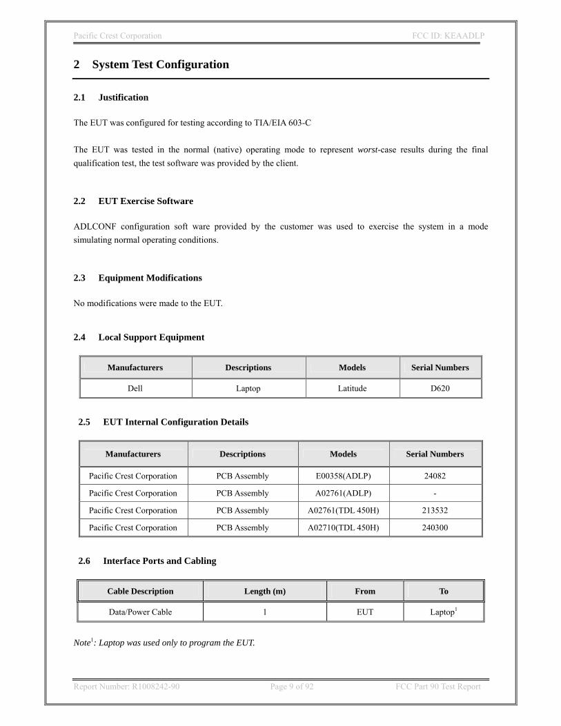
2 System Test Configuration
2.1 Justification The EUT was configured for testing according to TIA/EIA 603-C The EUT was tested in the normal (native) operating mode to represent worst-case results during the final qualification test, the test software was provided by the client. 2.2 EUT Exercise Software ADLCONF configuration soft ware provided by the customer was used to exercise the system in a mode simulating normal operating conditions. 2.3 Equipment Modifications No modifications were made to the EUT. 2.4 Local Support Equipment
Manufacturers Descriptions Models Serial Numbers
Dell Laptop Latitude D620
2.5 EUT Internal Configuration Details
Manufacturers Descriptions Models Serial Numbers
Pacific Crest Corporation PCB Assembly E00358(ADLP) 24082
Pacific Crest Corporation PCB Assembly A02761(ADLP) -
Pacific Crest Corporation PCB Assembly A02761(TDL 450H) 213532
Pacific Crest Corporation PCB Assembly A02710(TDL 450H) 240300
2.6 Interface Ports and Cabling
Cable Description Length (m) From To
Data/Power Cable 1 EUT Laptop1
Note1: Laptop was used only to program the EUT.

Pacific Crest Corporation FCC ID: KEAADLP
Report Number: R1008242-90 Page 10 of 92 FCC Part 90 Test Report
2.7 Power Supply Information
Manufacturer Description Model Serial Number
Mean Well AC Power Supply, Input:
100-240VAC 50/60Hz 4.0A Output: 12V 15A, 180W
GS220A12-R7B RB01061550

Pacific Crest Corporation FCC ID: KEAADLP
Report Number: R1008242-90 Page 11 of 92 FCC Part 90 Test Report
3 Summary of Test Results
FCC Rules Description of Tests Results
§2.1046 §90.205
RF Output Power Compliant1
§2.1047 Modulation Characteristics N/A
§2.1049 §90.209
Emission mask, Occupied Bandwidth Compliant1
§2.1051 §90.210
Spurious emissions at antenna terminals Compliant1
§2.1053 §90.210
Field strength of spurious radiation Compliant1
§2.1055 §90.213
Frequency stability vs. temperature Frequency stability vs. voltage
Compliant
§90.214 Transient Frequency Behavior Compliant1
§2.1091 RF Exposure Compliant
Note1: Tests were completed by Pacific Crest
N/A There is no specific requirement for digital modulation; therefore modulation characteristic is not presented.

Pacific Crest Corporation FCC ID: KEAADLP
Report Number: R1008242-90 Page 12 of 92 FCC Part 90 Test Report
4 FCC §2.1091 – RF Exposure Information
4.1 Applicable Standards According to FCC §2.1091 and §1.1307(b)(1), systems operating under the provisions of this section shall be operated in a manner that ensures that the public is not exposed to radio frequency energy level in excess of the Commission’s guidelines. According to §1.1310 and §2.1091 RF exposure is calculated.
Limits for General Population/Uncontrolled Exposure
Frequency Range (MHz)
Electric Field Strength
(V/m)
Magnetic Field Strength (A/m)
Power Density (mW/cm2)
Averaging Time
(minutes)
Limits for General Population/Uncontrolled Exposure
0.3-1.34 614 1.63 *(100) 30 1.34-30 824/f 2.19/f *(180/f2) 30 30-300 27.5 0.073 0.2 30
300-1500 / / f/1500 30 1500-100,000 / / 1.0 30
f = frequency in MHz * = Plane-wave equivalent power density 4.2 MPE Prediction Predication of MPE limit at a given distance
S = PG/4πR² Where: S = power density P = power input to antenna G = power gain of the antenna in the direction of interest relative to an isotropic radiator R = distance to the center of radiation of the antenna 390 ~ 430 MHz Band:
Maximum peak output power at antenna input terminal (dBm): 45.6
Maximum peak output power at antenna input terminal (mW): 36307.805
Duty Cycle: 50%
Maximum Corrected output power at antenna input terminal (mW): 18153.9025
Prediction distance (cm): 120
Prediction frequency (MHz): 390.05
Antenna Gain, typical (dBi): 5.0
Cable loss (dB): 1.0
Maximum Antenna Gain+ Cable Loss (numeric): 2.512
Power density at predication frequency and distance (mW/cm2): 0.252
MPE limit for uncontrolled exposure at prediction frequency (mW/cm2): 0.26

Pacific Crest Corporation FCC ID: KEAADLP
Report Number: R1008242-90 Page 13 of 92 FCC Part 90 Test Report
430 ~ 473 MHz Band:
Maximum peak output power at antenna input terminal (dBm): 45
Maximum peak output power at antenna input terminal (mW): 31622.777
Duty Cycle: 50%
Maximum Corrected output power at antenna input terminal (mW): 15811.3885
Prediction distance (cm): 120
Prediction frequency (MHz): 472.95
Antenna Gain, typical (dBi): 5.0
Cable loss (dB): 1.0
Maximum Antenna Gain+ Cable Loss (numeric): 2.512
Power density at predication frequency and distance (mW/cm2): 0.220
MPE limit for uncontrolled exposure at prediction frequency (mW/cm2): 0.3153
4.3 Result The device is compliant with the requirement MPE limit for uncontrolled exposure. 430-473 MHz maximum power density at the distance of 120 cm is 0.220 mW/cm2 (Limit 0.315 mW/cm2). The 390-430 MHz maximum power density at the distance of 120 cm is 0.252 mW/cm2 (Limit 0.26 mW/cm2).

Pacific Crest Corporation FCC ID: KEAADLP
Report Number: R1008242-90 Page 14 of 92 FCC Part 90 Test Report
5 FCC §2.1046 & §90.205 – RF Output Power
5.1 Applicable Standards Per FCC §2.1046 and §90.205: maximum ERP is dependent upon the station’s antenna HAAT and required service area. 5.2 Test Procedure The RF output of the transceiver was connected to a spectrum analyzer or a power meter through appropriate attenuator. 5.3 Test Equipment List and Details
Manufacturer Description Model S/N Cal Date
TekPower DC power supply HY3005D N/A N/A
HP Power Sensor 8482A US37293274 12/23/2009
HP Power Meter 435B 2235A06162 12/23/2009
Agilent Spectrum Analyzer 8562EC 3946A00187 12/23/2009
5.4 Test Environment Conditions
Temperature: 21~22 °C Relative Humidity: 70~75 %
ATM Pressure: 101.2-102.4kPa
The testing was performed by Jacinto Amante on 2010-07-28 & 2010-09-29

Pacific Crest Corporation FCC ID: KEAADLP
Report Number: R1008242-90 Page 15 of 92 FCC Part 90 Test Report
5.5 Test Results 390~430 MHz Band: S/N: 211505
Band (MHz)
Frequency (MHz)
Output Power in dBm
390.05 45.6 410.00 45.5 390~430 MHz
429.95 45.5
430~473 MHz Band: S/N: 211598
Band (MHz)
Frequency (MHz)
Output Power in dBm
430.05 44.6 450.00 44.4 430~473 MHz
472.95 45.0

Pacific Crest Corporation FCC ID: KEAADLP
Report Number: R1008242-90 Page 16 of 92 FCC Part 90 Test Report
6 FCC §2.1047 & §90.207 - Modulation Characteristic
6.1 Applicable Standard FCC §2.1047 & §90.207:
(a) Equipment which utilizes voice modulated communication shall show the frequency response of the audio modulating circuit over a range of 100 to 5000 Hz. for equipment which is required to have a low pass filter, the frequency response of the filter, or all of the circuitry installed between the modulation limited and the modulated stage shall be supplied.
(b) Equipment which employs modulation limiting, a curve showing the percentage of modulation versus the modulation input voltage shall be supplied.
6.2 Test Procedure TIA-603-C §2.2.3 6.3 Test Results
N/A; There is no specific requirement for digital modulation; therefore modulation characteristic is not presented.
Pacific Crest Corporation FCC ID: KEAADLP
Report Number: R1008242-90 Page 17 of 92 FCC Part 90 Test Report
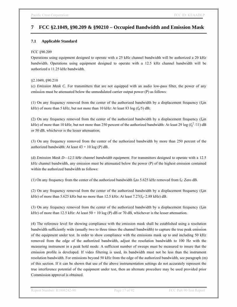
7 FCC §2.1049, §90.209 & §90210 – Occupied Bandwidth and Emission Mask
7.1 Applicable Standard FCC §90.209 Operations using equipment designed to operate with a 25 kHz channel bandwidth will be authorized a 20 kHz bandwidth. Operations using equipment designed to operate with a 12.5 kHz channel bandwidth will be authorized a 11.25 kHz bandwidth. §2.1049, §90.210 (c) Emission Mask C. For transmitters that are not equipped with an audio low-pass filter, the power of any emission must be attenuated below the unmodulated carrier output power (P) as follows:
(1) On any frequency removed from the center of the authorized bandwidth by a displacement frequency (fdin kHz) of more than 5 kHz, but not more than 10 kHz: At least 83 log (fd/5) dB;
(2) On any frequency removed from the center of the authorized bandwidth by a displacement frequency (fdin kHz) of more than 10 kHz, but not more than 250 percent of the authorized bandwidth: At least 29 log (fd
2 /11) dB or 50 dB, whichever is the lesser attenuation;
(3) On any frequency removed from the center of the authorized bandwidth by more than 250 percent of the authorized bandwidth: At least 43 + 10 log (P) dB.
(d) Emission Mask D—12.5 kHz channel bandwidth equipment. For transmitters designed to operate with a 12.5 kHz channel bandwidth, any emission must be attenuated below the power (P) of the highest emission contained within the authorized bandwidth as follows:
(1) On any frequency from the center of the authorized bandwidth f0to 5.625 kHz removed from f0: Zero dB.
(2) On any frequency removed from the center of the authorized bandwidth by a displacement frequency (fdin kHz) of more than 5.625 kHz but no more than 12.5 kHz: At least 7.27(fd−2.88 kHz) dB.
(3) On any frequency removed from the center of the authorized bandwidth by a displacement frequency (fdin kHz) of more than 12.5 kHz: At least 50 + 10 log (P) dB or 70 dB, whichever is the lesser attenuation.
(4) The reference level for showing compliance with the emission mask shall be established using a resolution bandwidth sufficiently wide (usually two to three times the channel bandwidth) to capture the true peak emission of the equipment under test. In order to show compliance with the emissions mask up to and including 50 kHz removed from the edge of the authorized bandwidth, adjust the resolution bandwidth to 100 Hz with the measuring instrument in a peak hold mode. A sufficient number of sweeps must be measured to insure that the emission profile is developed. If video filtering is used, its bandwidth must not be less than the instrument resolution bandwidth. For emissions beyond 50 kHz from the edge of the authorized bandwidth, see paragraph (m) of this section. If it can be shown that use of the above instrumentation settings do not accurately represent the true interference potential of the equipment under test, then an alternate procedure may be used provided prior Commission approval is obtained.

Pacific Crest Corporation FCC ID: KEAADLP
Report Number: R1008242-90 Page 18 of 92 FCC Part 90 Test Report
7.2 Test Procedure The RF output of the transmitter was connected to the input of the spectrum analyzer through sufficient attenuation. The resolution bandwidth of the spectrum analyzer was set at 100 Hz and the spectrum was recorded in the frequency band ±50 KHz or + 25 kHz from the carrier frequency. 7.3 Test Equipment List and Details
Manufacturer Description Model S/N Cal Date
Agilent Spectrum Analyzer 8562EC 3946A00187 12/23/2009
TekPower DC power supply HY3005D N/A N/A
7.4 Test Environment Conditions
Temperature: 21~22 °C Relative Humidity: 70~75 %
ATM Pressure: 101.2-102.4kPa
The testing was performed by Hui Chen on 2010-07-26, 2010-08-19, & 2010-08-20 7.5 Test Results
Modulation Emission C Result Emission D Result
19200 bit rate Compliant 9600 bit rate Compliant 16000 bit rate Compliant 8000 bit rate Compliant 9600 bit rate Compliant 4800 bit rate Compliant
GMSK
4800 bit rate Complaint / / 4 FSK 19200 bit rate Compliant 9600 bit rate Compliant

Pacific Crest Corporation FCC ID: KEAADLP
Report Number: R1008242-90 Page 19 of 92 FCC Part 90 Test Report
S/N: 211505 (390~430 MHz)
390.05 MHz GMSK Emissions C
dBm 50
40
30
20
10
0
-10
-20
-30
-40
-50
SoftPlot Measurement Presentation19200-0.3BT-3.7KHz deviation16000-0.3-3.7KHz9600-0.5-3.7KHz
4800-0.5-3.7KHz
Start: 390.025000 MHz Stop: 390.075000 MHzAtten: 40 dBRes BW: 300 Hz Vid BW: 300 Hz Sweep: 1 s8/20/2010 2:49:45 PM HP8562E,007FCC_39~1.SPT
PASS
11 19200-0.3BT-3.7KH
390.050000 MHz 39.5000 dBm2
2 4800-0.5-3.7KHz 390.050000 MHz 32.0000 dBm
3
3 9600-0.5-3.7KHz 390.050000 MHz 30.8400 dBm
390.05 MHz GMSK Emission D
dBm 50
40
30
20
10
0
-10
-20
-30
-40
-50
SoftPlot Measurement Presentation9600-0.3-2.0k 8000-0.3-2.0KHz 4800_0.5-2.0KHz
Start: 390.025000 MHz Stop: 390.075000 MHzAtten: 40 dBRes BW: 300 Hz Vid BW: 300 Hz Sweep: 1 s8/19/2010 3:48:33 PM HP8562E,007FCC_39~3.SPT
PASS
11 4800_0.5-2.0KHz
390.050000 MHz 39.5000 dBm
22 9600-0.3-2.0k
390.049750 MHz 30.0000 dBm

Pacific Crest Corporation FCC ID: KEAADLP
Report Number: R1008242-90 Page 20 of 92 FCC Part 90 Test Report
390.05 MHz 4LFSK Emissions C
dBm 50
40
30
20
10
0
-10
-20
-30
-40
-50
SoftPlot Measurement Presentation19200-4.5KHz deviation
Start: 390.025000 MHz Stop: 390.075000 MHzAtten: 40 dBRes BW: 300 Hz Vid BW: 300 Hz Sweep: 1 s8/19/2010 3:31:27 PM HP8562E,007FCC_39~2.SPT
PASS
1
1 19200-4.5KHz devia 390.050000 MHz 34.6700 dBm2
2 19200-4.5KHz devia 390.051917 MHz 33.1700 dBm
3
3 19200-4.5KHz devia 390.049750 MHz 25.0000 dBm
390.05 MHz 4LFSK Emissions D
dBm 50
40
30
20
10
0
-10
-20
-30
-40
-50
SoftPlot Measurement Presentation9600-2.4k
Start: 390.025000 MHz Stop: 390.075000 MHzAtten: 40 dBRes BW: 300 Hz Vid BW: 300 Hz Sweep: 1 s8/20/2010 10:46:37 AM HP8562E,00739005M~1.SPT
PASS
11 9600-2.4k
390.050000 MHz 37.8400 dBm
2
2 9600-2.4k 390.051917 MHz 21.0000 dBm

Pacific Crest Corporation FCC ID: KEAADLP
Report Number: R1008242-90 Page 21 of 92 FCC Part 90 Test Report
410 MHz GMSK Emissions C
dBm 50
40
30
20
10
0
-10
-20
-30
-40
-50
SoftPlot Measurement Presentation19200-0.3BT-3.7KHz deviation16000-0.3-3.7KHz9600-0.5-3.7KHz
4800-0.5-3.7KHz
Start: 409.975000 MHz Stop: 410.025000 MHzAtten: 40 dBRes BW: 300 Hz Vid BW: 300 Hz Sweep: 1 s8/20/2010 2:52:38 PM HP8562E,007FCC_41~1.SPT
PASS
1
1 19200-0.3BT-3.7KH 410.000000 MHz 36.1700 dBm2
2 19200-0.3BT-3.7KH 409.999750 MHz 33.1700 dBm
3
3 4800-0.5-3.7KHz 410.000000 MHz 32.0000 dBm
410 MHz GMSK Emission D
dBm 50
40
30
20
10
0
-10
-20
-30
-40
-50
SoftPlot Measurement Presentation9600-0.3-2.0k 8000-0.3-2.0KHz 4800_0.5-2.0KHz
Start: 409.975000 MHz Stop: 410.025000 MHzAtten: 40 dBRes BW: 300 Hz Vid BW: 300 Hz Sweep: 1 s8/19/2010 3:50:06 PM HP8562E,007FCC_41~3.SPT
PASS
11 4800_0.5-2.0KHz
410.000000 MHz 39.5000 dBm
2
2 9600-0.3-2.0k 409.999750 MHz 36.5000 dBm

Pacific Crest Corporation FCC ID: KEAADLP
Report Number: R1008242-90 Page 22 of 92 FCC Part 90 Test Report
410 MHz 4LFSK Emissions C
dBm 50
40
30
20
10
0
-10
-20
-30
-40
-50
SoftPlot Measurement Presentation19200-4.5KHz deviation
Start: 409.975000 MHz Stop: 410.025000 MHzAtten: 40 dBRes BW: 300 Hz Vid BW: 300 Hz Sweep: 1 s8/19/2010 3:28:10 PM HP8562E,007FCC_41~2.SPT
PASS
1
1 19200-4.5KHz devia 410.000000 MHz 36.0000 dBm
22 19200-4.5KHz devia
410.001917 MHz 29.6700 dBm
3
3 19200-4.5KHz devia 409.999750 MHz 27.5000 dBm
410 MHz 4LFSK Emissions D
dBm 50
40
30
20
10
0
-10
-20
-30
-40
-50
SoftPlot Measurement Presentation9600-2.4k
Start: 409.975000 MHz Stop: 410.025000 MHzAtten: 40 dBRes BW: 300 Hz Vid BW: 300 Hz Sweep: 1 s8/20/2010 10:52:18 AM HP8562E,007410MHZ~1.SPT
PASS
11 9600-2.4k
410.000000 MHz 37.5000 dBm2
2 9600-2.4k 410.001917 MHz 32.8400 dBm
Pacific Crest Corporation FCC ID: KEAADLP
Report Number: R1008242-90 Page 23 of 92 FCC Part 90 Test Report
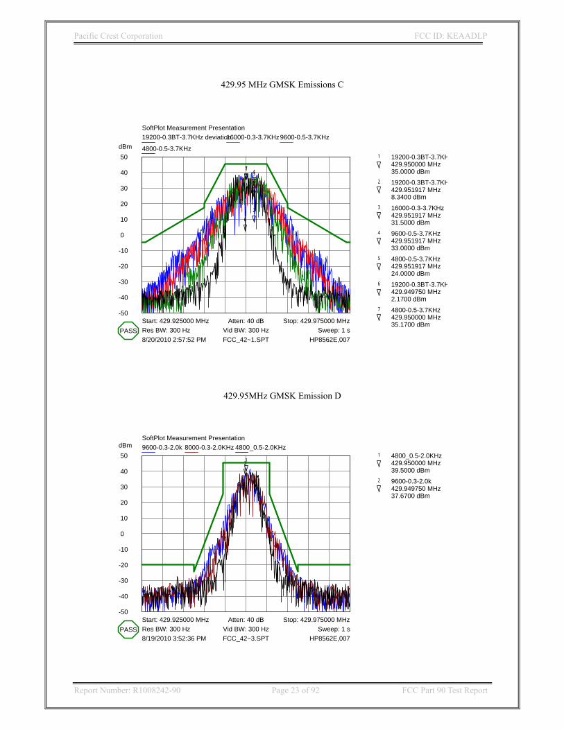
429.95 MHz GMSK Emissions C
dBm 50
40
30
20
10
0
-10
-20
-30
-40
-50
SoftPlot Measurement Presentation19200-0.3BT-3.7KHz deviation16000-0.3-3.7KHz9600-0.5-3.7KHz
4800-0.5-3.7KHz
Start: 429.925000 MHz Stop: 429.975000 MHzAtten: 40 dBRes BW: 300 Hz Vid BW: 300 Hz Sweep: 1 s8/20/2010 2:57:52 PM HP8562E,007FCC_42~1.SPT
PASS
1
1 19200-0.3BT-3.7KH 429.950000 MHz 35.0000 dBm
2
2 19200-0.3BT-3.7KH 429.951917 MHz 8.3400 dBm
3
3 16000-0.3-3.7KHz 429.951917 MHz 31.5000 dBm
4
4 9600-0.5-3.7KHz 429.951917 MHz 33.0000 dBm
5
5 4800-0.5-3.7KHz 429.951917 MHz 24.0000 dBm
6
6 19200-0.3BT-3.7KH 429.949750 MHz 2.1700 dBm
7
7 4800-0.5-3.7KHz 429.950000 MHz 35.1700 dBm
429.95MHz GMSK Emission D
dBm 50
40
30
20
10
0
-10
-20
-30
-40
-50
SoftPlot Measurement Presentation9600-0.3-2.0k 8000-0.3-2.0KHz 4800_0.5-2.0KHz
Start: 429.925000 MHz Stop: 429.975000 MHzAtten: 40 dBRes BW: 300 Hz Vid BW: 300 Hz Sweep: 1 s8/19/2010 3:52:36 PM HP8562E,007FCC_42~3.SPT
PASS
11 4800_0.5-2.0KHz
429.950000 MHz 39.5000 dBm
2
2 9600-0.3-2.0k 429.949750 MHz 37.6700 dBm
Pacific Crest Corporation FCC ID: KEAADLP
Report Number: R1008242-90 Page 24 of 92 FCC Part 90 Test Report
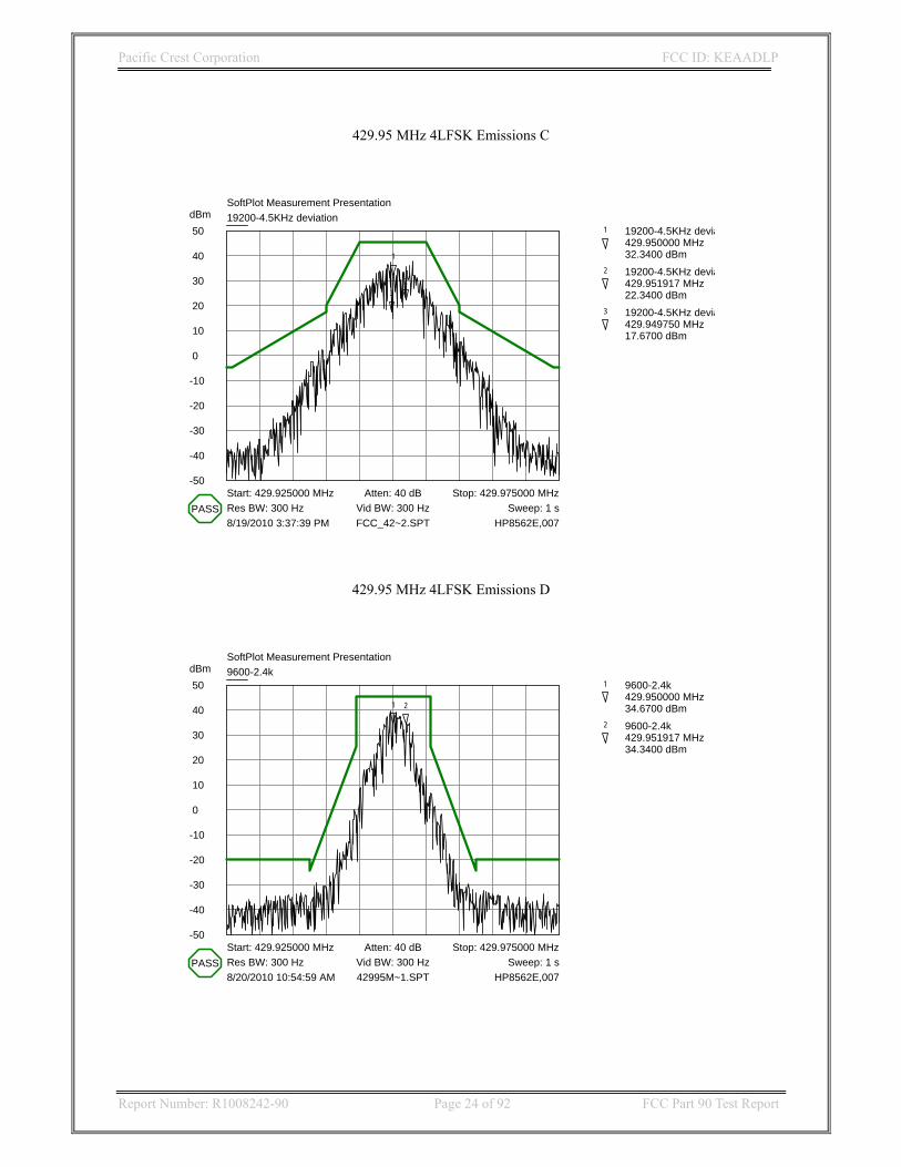
429.95 MHz 4LFSK Emissions C
dBm 50
40
30
20
10
0
-10
-20
-30
-40
-50
SoftPlot Measurement Presentation19200-4.5KHz deviation
Start: 429.925000 MHz Stop: 429.975000 MHzAtten: 40 dBRes BW: 300 Hz Vid BW: 300 Hz Sweep: 1 s8/19/2010 3:37:39 PM HP8562E,007FCC_42~2.SPT
PASS
1
1 19200-4.5KHz devia 429.950000 MHz 32.3400 dBm
22 19200-4.5KHz devia
429.951917 MHz 22.3400 dBm3
3 19200-4.5KHz devia 429.949750 MHz 17.6700 dBm
429.95 MHz 4LFSK Emissions D
dBm 50
40
30
20
10
0
-10
-20
-30
-40
-50
SoftPlot Measurement Presentation9600-2.4k
Start: 429.925000 MHz Stop: 429.975000 MHzAtten: 40 dBRes BW: 300 Hz Vid BW: 300 Hz Sweep: 1 s8/20/2010 10:54:59 AM HP8562E,00742995M~1.SPT
PASS
1
1 9600-2.4k 429.950000 MHz 34.6700 dBm2
2 9600-2.4k 429.951917 MHz 34.3400 dBm
Pacific Crest Corporation FCC ID: KEAADLP
Report Number: R1008242-90 Page 25 of 92 FCC Part 90 Test Report
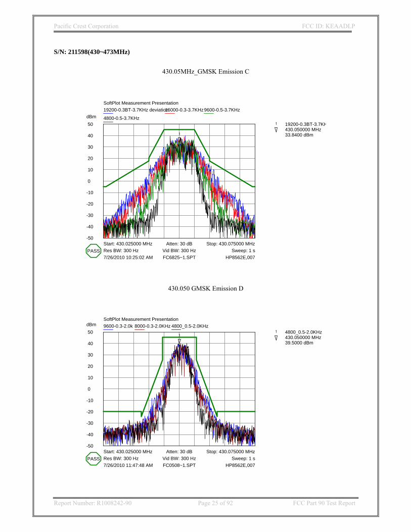
S/N: 211598(430~473MHz)
430.05MHz_GMSK Emission C
dBm 50
40
30
20
10
0
-10
-20
-30
-40
-50
SoftPlot Measurement Presentation19200-0.3BT-3.7KHz deviation16000-0.3-3.7KHz9600-0.5-3.7KHz
4800-0.5-3.7KHz
Start: 430.025000 MHz Stop: 430.075000 MHzAtten: 30 dBRes BW: 300 Hz Vid BW: 300 Hz Sweep: 1 s7/26/2010 10:25:02 AM HP8562E,007FC6825~1.SPT
PASS
1
1 19200-0.3BT-3.7KH 430.050000 MHz 33.8400 dBm
430.050 GMSK Emission D
dBm 50
40
30
20
10
0
-10
-20
-30
-40
-50
SoftPlot Measurement Presentation9600-0.3-2.0k 8000-0.3-2.0KHz 4800_0.5-2.0KHz
Start: 430.025000 MHz Stop: 430.075000 MHzAtten: 30 dBRes BW: 300 Hz Vid BW: 300 Hz Sweep: 1 s7/26/2010 11:47:48 AM HP8562E,007FC0508~1.SPT
PASS
11 4800_0.5-2.0KHz
430.050000 MHz 39.5000 dBm

Pacific Crest Corporation FCC ID: KEAADLP
Report Number: R1008242-90 Page 26 of 92 FCC Part 90 Test Report
430.05 MHz 4LFSK Emissions C
dBm 50
40
30
20
10
0
-10
-20
-30
-40
-50
SoftPlot Measurement Presentation19200-4.5KHz deviation
Start: 430.025000 MHz Stop: 430.075000 MHzAtten: 30 dBRes BW: 300 Hz Vid BW: 300 Hz Sweep: 1 s7/26/2010 11:25:25 AM HP8562E,007FC0080~1.SPT
PASS
1
1 19200-4.5KHz devia 430.050000 MHz 33.8400 dBm
2
2 19200-4.5KHz devia 430.051917 MHz 19.1700 dBm
430.05 MHz 4LFSK Emissions D
dBm 50
40
30
20
10
0
-10
-20
-30
-40
-50
SoftPlot Measurement Presentation9600-2.4k
Start: 430.025000 MHz Stop: 430.075000 MHzAtten: 30 dBRes BW: 300 Hz Vid BW: 300 Hz Sweep: 1 s7/26/2010 2:21:09 PM HP8562E,007FC9E3E~1.SPT
PASS
1
1 9600-2.4k 430.050000 MHz 32.1700 dBm2
2 9600-2.4k 430.051917 MHz 31.8400 dBm
Pacific Crest Corporation FCC ID: KEAADLP
Report Number: R1008242-90 Page 27 of 92 FCC Part 90 Test Report
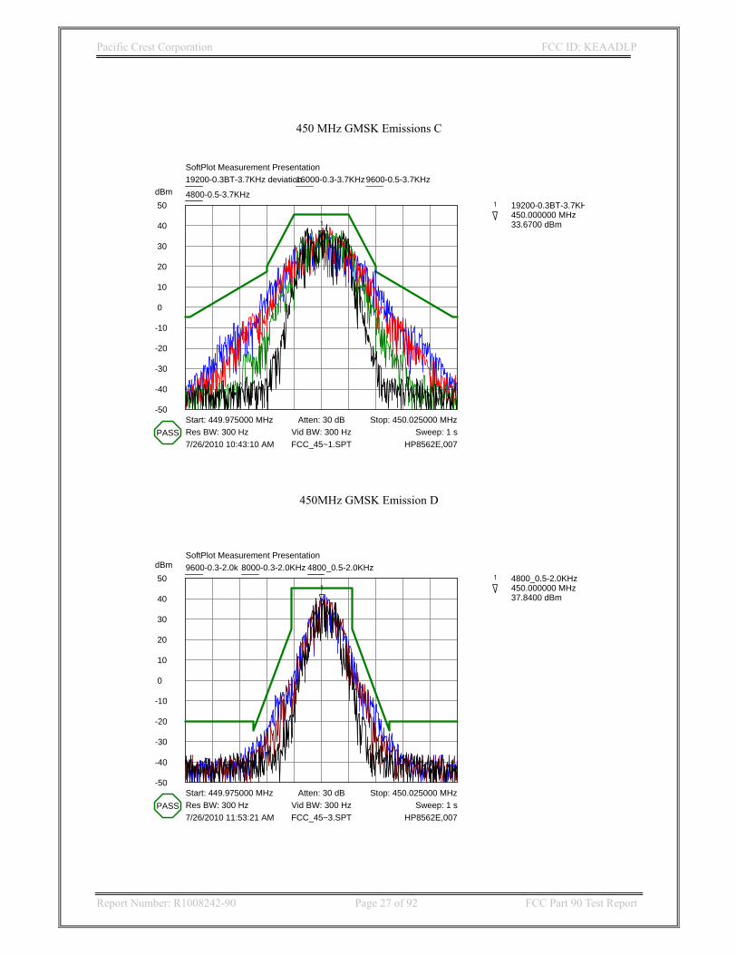
450 MHz GMSK Emissions C
dBm 50
40
30
20
10
0
-10
-20
-30
-40
-50
SoftPlot Measurement Presentation19200-0.3BT-3.7KHz deviation16000-0.3-3.7KHz9600-0.5-3.7KHz
4800-0.5-3.7KHz
Start: 449.975000 MHz Stop: 450.025000 MHzAtten: 30 dBRes BW: 300 Hz Vid BW: 300 Hz Sweep: 1 s7/26/2010 10:43:10 AM HP8562E,007FCC_45~1.SPT
PASS
1
1 19200-0.3BT-3.7KH 450.000000 MHz 33.6700 dBm
450MHz GMSK Emission D
dBm 50
40
30
20
10
0
-10
-20
-30
-40
-50
SoftPlot Measurement Presentation9600-0.3-2.0k 8000-0.3-2.0KHz 4800_0.5-2.0KHz
Start: 449.975000 MHz Stop: 450.025000 MHzAtten: 30 dBRes BW: 300 Hz Vid BW: 300 Hz Sweep: 1 s7/26/2010 11:53:21 AM HP8562E,007FCC_45~3.SPT
PASS
11 4800_0.5-2.0KHz
450.000000 MHz 37.8400 dBm

Pacific Crest Corporation FCC ID: KEAADLP
Report Number: R1008242-90 Page 28 of 92 FCC Part 90 Test Report
450 MHz 4LFSK Emissions C
dBm 50
40
30
20
10
0
-10
-20
-30
-40
-50
SoftPlot Measurement Presentation19200-4.5KHz deviation
Start: 449.975000 MHz Stop: 450.025000 MHzAtten: 30 dBRes BW: 300 Hz Vid BW: 300 Hz Sweep: 1 s7/26/2010 11:23:54 AM HP8562E,007FCC_45~2.SPT
PASS
1
1 19200-4.5KHz devia 450.000000 MHz 29.6700 dBm
2
2 19200-4.5KHz devia 450.001917 MHz 36.0000 dBm
450 MHz 4LFSK Emissions D
dBm 50
40
30
20
10
0
-10
-20
-30
-40
-50
SoftPlot Measurement Presentation9600-2.4k
Start: 449.975000 MHz Stop: 450.025000 MHzAtten: 30 dBRes BW: 300 Hz Vid BW: 300 Hz Sweep: 1 s7/26/2010 2:16:17 PM HP8562E,007FCC_45~4.SPT
PASS
1 1 9600-2.4k 450.000000 MHz 41.8400 dBm

Pacific Crest Corporation FCC ID: KEAADLP
Report Number: R1008242-90 Page 29 of 92 FCC Part 90 Test Report
472.95 MHz GMSK Emissions C
dBm 50
40
30
20
10
0
-10
-20
-30
-40
-50
SoftPlot Measurement Presentation19200-0.3BT-3.7KHz deviation16000-0.3-3.7KHz9600-0.5-3.7KHz
4800-0.5-3.7KHz
Start: 472.925000 MHz Stop: 472.975000 MHzAtten: 40 dBRes BW: 300 Hz Vid BW: 300 Hz Sweep: 1 s9/17/2010 10:55:01 AM HP8562E,007FCC472~1.SPT
PASS
1
1 19200-0.3BT-3.7KH 472.950000 MHz 35.1700 dBm
472.95 MHz GMSK Emission D
dBm 50
40
30
20
10
0
-10
-20
-30
-40
-50
SoftPlot Measurement Presentation9600-0.3-2.0k 8000-0.3-2.0KHz 4800_0.5-2.0KHz
Start: 472.925000 MHz Stop: 472.975000 MHzAtten: 40 dBRes BW: 300 Hz Vid BW: 300 Hz Sweep: 1 s9/17/2010 11:04:11 AM HP8562E,007FCC_47~1.SPT
PASS
1
1 4800_0.5-2.0KHz 472.950000 MHz 32.8400 dBm

Pacific Crest Corporation FCC ID: KEAADLP
Report Number: R1008242-90 Page 30 of 92 FCC Part 90 Test Report
472.95 MHz 4LFSK Emissions C
dBm 50
40
30
20
10
0
-10
-20
-30
-40
-50
SoftPlot Measurement Presentation19200-4.5KHz deviation
Start: 472.925000 MHz Stop: 472.975000 MHzAtten: 40 dBRes BW: 300 Hz Vid BW: 300 Hz Sweep: 1 s9/17/2010 11:20:48 AM HP8562E,007FCC472~3.SPT
PASS
1
1 19200-4.5KHz devia 472.950000 MHz 35.0000 dBm2
2 19200-4.5KHz devia 472.951917 MHz 33.3400 dBm
3
3 19200-4.5KHz devia 472.975000 MHz-39.0000 dBm
472.95 MHz 4LFSK Emissions D
dBm 50
40
30
20
10
0
-10
-20
-30
-40
-50
SoftPlot Measurement Presentation9600-2.4k
Start: 472.925000 MHz Stop: 472.975000 MHzAtten: 40 dBRes BW: 300 Hz Vid BW: 300 Hz Sweep: 1 s9/17/2010 11:18:16 AM HP8562E,007FCC472~2.SPT
PASS
1
1 9600-2.4k 472.974917 MHz-38.1600 dBm
2 2 9600-2.4k 472.951917 MHz 24.8400 dBm

Pacific Crest Corporation FCC ID: KEAADLP
Report Number: R1008242-90 Page 31 of 92 FCC Part 90 Test Report
8 FCC §2.1051 & §90.210 – Spurious Emissions at Antenna Terminals
8.1 Applicable Standard FCC §2.1051 and §90.210. On any frequency removed from the center of the authorized bandwidth by a displacement frequency (fd in kHz) of more than 12.5 kHz at least: 50+10logP or 70 dB On any frequency removed from the center of the assigned channel by more than 250 percent at least: 43+10log (P) 8.2 Test Procedure TIA-603-C §2.2.13 8.3 Test Equipment List and Details
Manufacturer Description Model S/N Cal Date
Agilent Spectrum Analyzer 8562EC 3946A00288 12/22/2009
TekPower DC power supply HY3005D N/A N/A
8.4 Test Environment Conditions
Temperature: 21~22 °C Relative Humidity: 70~75 %
ATM Pressure: 101.2-102.4kPa
The testing was performed by Hui Chen on 2010-07-21~ 2010-09-01

Pacific Crest Corporation FCC ID: KEAADLP
Report Number: R1008242-90 Page 32 of 92 FCC Part 90 Test Report
8.5 Test Results 390~430 MHz(S/N: 211505)
TX Operation TX Standby TX Operation TX Standby
Freq. (MHz)
Output Power (dBm)
Freq. (MHz)
Output Power (dBm)
Freq. (MHz)
Output Power (dBm)
Freq. (MHz)
Output Power (dBm)
Fundamental 390.05 44.8 444.5 -75.2 410.00 45.1 464.45 -72.1
2nd Harmonic 780.1 -57.2 889 -87.2 820.00 -58.2 928.90 -82.5 3rd Harmonic 1170.15 -45.5 1333.5 -67.4 1230.00 -60.2 1393.35 -75.0 4th Harmonic 1560.2 <-60 1778 <-70 1640.00 <-60 1857.80 <-70 5th Harmonic 1950.25 <-60 2222.5 <-70 2050.00 <-60 2322.25 <-70 6th Harmonic 2340.3 <-60 2667 <-70 2460.00 <-60 2786.70 <-70 7th Harmonic 2730.35 <-60 3111.5 <-70 2870.00 <-60 3251.15 <-60 8th Harmonic 3120.4 <-60 3556 <-70 3280.00 <-60 3715.60 <-70 9th Harmonic 3510.45 <-60 4000.5 <-70 3690.00 <-60 4180.05 <-70 10th Harmonic 3900.5 <-60 4445 <-70 4100.00 <-60 4644.50 <-70
390~430 MHz(S/N: 211505)
TX Operation TX Standby
Freq. (MHz)
Output Power (dBm)
Freq. (MHz)
Output Power (dBm)
Fundamental 429.95 45.1 484.4 -70 2nd Harmonic 859.9 -61 968.8 -86 3rd Harmonic 1289.85 -65 1453.2 -70 4th Harmonic 1719.8 <-70 1937.6 <-70 5th Harmonic 2149.75 <-70 2422 <-70 6th Harmonic 2579.7 <-70 2906.4 <-70 7th Harmonic 3009.65 <-70 3390.8 -50 8th Harmonic 3439.6 <-70 3875.2 <-70 9th Harmonic 3869.55 <-70 4359.6 <-70 10th Harmonic 4299.5 <-70 4844 <-70
Pacific Crest Corporation FCC ID: KEAADLP
Report Number: R1008242-90 Page 33 of 92 FCC Part 90 Test Report
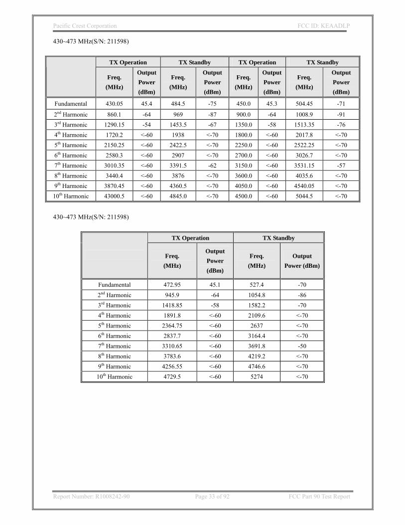
430~473 MHz(S/N: 211598)
TX Operation TX Standby TX Operation TX Standby
Freq. (MHz)
Output Power (dBm)
Freq. (MHz)
Output Power (dBm)
Freq. (MHz)
Output Power (dBm)
Freq. (MHz)
Output Power (dBm)
Fundamental 430.05 45.4 484.5 -75 450.0 45.3 504.45 -71
2nd Harmonic 860.1 -64 969 -87 900.0 -64 1008.9 -91 3rd Harmonic 1290.15 -54 1453.5 -67 1350.0 -58 1513.35 -76 4th Harmonic 1720.2 <-60 1938 <-70 1800.0 <-60 2017.8 <-70 5th Harmonic 2150.25 <-60 2422.5 <-70 2250.0 <-60 2522.25 <-70 6th Harmonic 2580.3 <-60 2907 <-70 2700.0 <-60 3026.7 <-70 7th Harmonic 3010.35 <-60 3391.5 -62 3150.0 <-60 3531.15 -57 8th Harmonic 3440.4 <-60 3876 <-70 3600.0 <-60 4035.6 <-70 9th Harmonic 3870.45 <-60 4360.5 <-70 4050.0 <-60 4540.05 <-70 10th Harmonic 43000.5 <-60 4845.0 <-70 4500.0 <-60 5044.5 <-70
430~473 MHz(S/N: 211598)
TX Operation TX Standby
Freq. (MHz)
Output Power (dBm)
Freq. (MHz)
Output Power (dBm)
Fundamental 472.95 45.1 527.4 -70
2nd Harmonic 945.9 -64 1054.8 -86 3rd Harmonic 1418.85 -58 1582.2 -70 4th Harmonic 1891.8 <-60 2109.6 <-70 5th Harmonic 2364.75 <-60 2637 <-70 6th Harmonic 2837.7 <-60 3164.4 <-70 7th Harmonic 3310.65 <-60 3691.8 -50 8th Harmonic 3783.6 <-60 4219.2 <-70 9th Harmonic 4256.55 <-60 4746.6 <-70 10th Harmonic 4729.5 <-60 5274 <-70
Pacific Crest Corporation FCC ID: KEAADLP
Report Number: R1008242-90 Page 34 of 92 FCC Part 90 Test Report
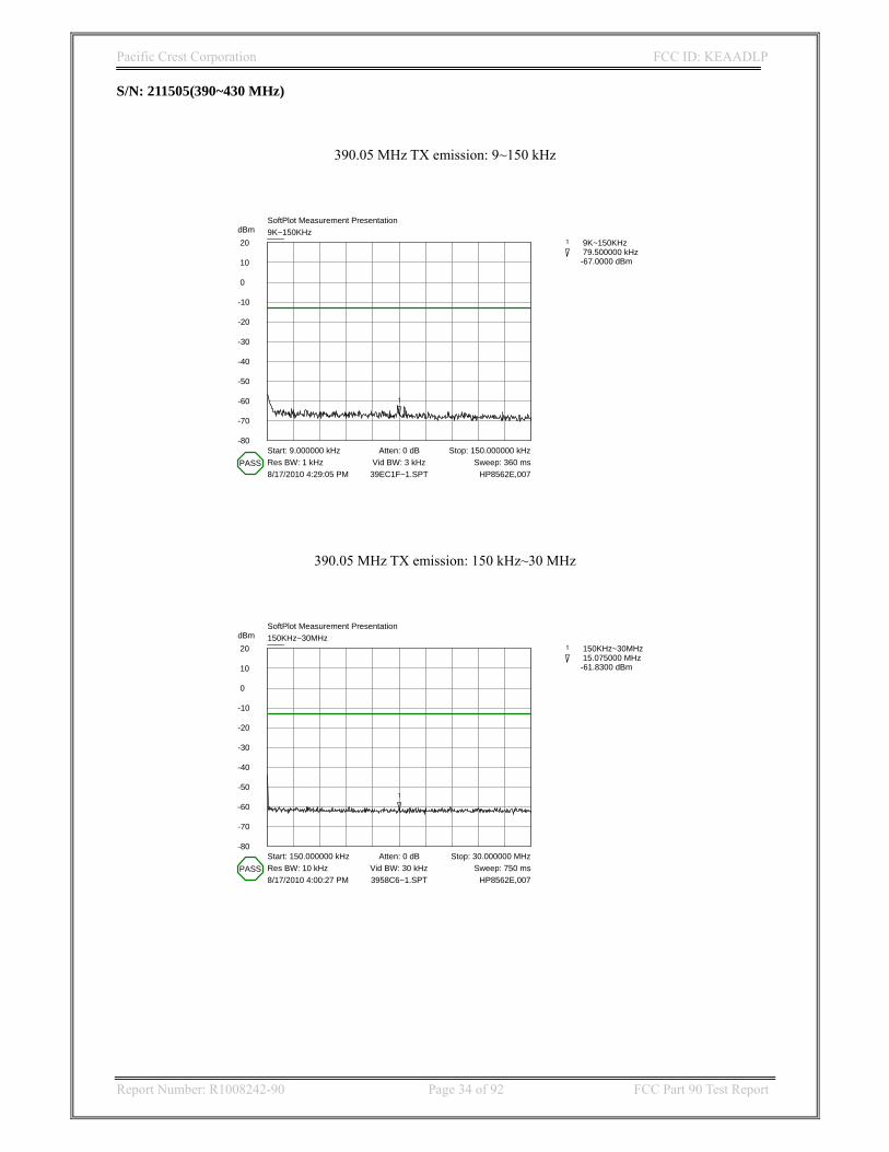
S/N: 211505(390~430 MHz)
390.05 MHz TX emission: 9~150 kHz
dBm 20
10
0
-10
-20
-30
-40
-50
-60
-70
-80
SoftPlot Measurement Presentation9K~150KHz
Start: 9.000000 kHz Stop: 150.000000 kHzAtten: 0 dBRes BW: 1 kHz Vid BW: 3 kHz Sweep: 360 ms8/17/2010 4:29:05 PM HP8562E,00739EC1F~1.SPT
PASS
1
1 9K~150KHz 79.500000 kHz-67.0000 dBm
390.05 MHz TX emission: 150 kHz~30 MHz
dBm 20
10
0
-10
-20
-30
-40
-50
-60
-70
-80
SoftPlot Measurement Presentation150KHz~30MHz
Start: 150.000000 kHz Stop: 30.000000 MHzAtten: 0 dBRes BW: 10 kHz Vid BW: 30 kHz Sweep: 750 ms8/17/2010 4:00:27 PM HP8562E,0073958C6~1.SPT
PASS
1
1 150KHz~30MHz 15.075000 MHz-61.8300 dBm

Pacific Crest Corporation FCC ID: KEAADLP
Report Number: R1008242-90 Page 35 of 92 FCC Part 90 Test Report
390.05 MHz TX emission: 30 MHz~1 GHz (Notch filter is needed to reject carrier)
dBm 20
10
0
-10
-20
-30
-40
-50
-60
-70
-80
SoftPlot Measurement Presentation30MHz~1GHz
Start: 30.000000 MHz Stop: 1.000000 GHzAtten: 0 dBRes BW: 100 kHz Vid BW: 300 kHz Sweep: 250 ms8/17/2010 3:30:24 PM HP8562E,007397A2C~1.SPT
1
1 30MHz~1GHz 388.900000 MHz-1.0000 dBm
2
2 30MHz~1GHz 780.133333 MHz-49.3300 dBm
390.05 MHz TX emission: 1 GHz~4 GHz
dBm 20
10
0
-10
-20
-30
-40
-50
-60
-70
-80
SoftPlot Measurement Presentation1GHz~4GHz
Start: 1.000000 GHz Stop: 4.000000 GHzAtten: 0 dBRes BW: 1 MHz Vid BW: 3 MHz Sweep: 60 ms8/17/2010 3:35:23 PM HP8562E,007399437~1.SPT
PASS
1
1 1GHz~4GHz 1.170000 GHz-35.3300 dBm

Pacific Crest Corporation FCC ID: KEAADLP
Report Number: R1008242-90 Page 36 of 92 FCC Part 90 Test Report
390.05 MHz RX emission: 9~150 kHz
dBm-10
-20
-30
-40
-50
-60
-70
-80
-90
-100
-110
SoftPlot Measurement Presentation9K~150KHz
Start: 9.000000 kHz Stop: 150.000000 kHzAtten: 0 dBRes BW: 1 kHz Vid BW: 3 kHz Sweep: 360 ms8/19/2010 10:24:29 AM HP8562E,00739005M~1.SPT
PASS
1
1 9K~150KHz 79.500000 kHz-96.3300 dBm
390.05 MHz RX emission: 150 kHz~30 MHz
dBm-10
-20
-30
-40
-50
-60
-70
-80
-90
-100
-110
SoftPlot Measurement Presentation150KHz~30MHz
Start: 150.000000 kHz Stop: 30.000000 MHzAtten: 0 dBRes BW: 10 kHz Vid BW: 30 kHz Sweep: 750 ms8/16/2010 5:18:28 PM HP8562E,00739005M~2.SPT
PASS
1
1 150KHz~30MHz 15.075000 MHz-93.6600 dBm

Pacific Crest Corporation FCC ID: KEAADLP
Report Number: R1008242-90 Page 37 of 92 FCC Part 90 Test Report
390.05 MHz RX emission: 30 MHz~1 GHz
dBm-10
-20
-30
-40
-50
-60
-70
-80
-90
-100
-110
SoftPlot Measurement Presentation30MHz~1GHz
Start: 30.000000 MHz Stop: 1.000000 GHzAtten: 0 dBRes BW: 100 kHz Vid BW: 300 kHz Sweep: 250 ms8/16/2010 5:24:34 PM HP8562E,00739005M~3.SPT
PASS
1
1 30MHz~1GHz 448.716667 MHz-87.3300 dBm
2
2 30MHz~1GHz 515.000000 MHz-86.8300 dBm
390.05 MHz RX emission: 1 GHz~4 GHz
dBm-10
-20
-30
-40
-50
-60
-70
-80
-90
-100
-110
SoftPlot Measurement Presentation1GHz~4GHz
Start: 1.000000 GHz Stop: 4.000000 GHzAtten: 0 dBRes BW: 1 MHz Vid BW: 3 MHz Sweep: 60 ms8/16/2010 5:25:51 PM HP8562E,00739005M~4.SPT
PASS
1
1 1GHz~4GHz 1.290000 GHz-76.5000 dBm

Pacific Crest Corporation FCC ID: KEAADLP
Report Number: R1008242-90 Page 38 of 92 FCC Part 90 Test Report
410 MHz TX emission: 9~150 kHz
dBm 20
10
0
-10
-20
-30
-40
-50
-60
-70
-80
SoftPlot Measurement Presentation9K~150KHz
Start: 9.000000 kHz Stop: 150.000000 kHzAtten: 0 dBRes BW: 1 kHz Vid BW: 3 kHz Sweep: 360 ms8/18/2010 11:09:14 AM HP8562E,0074184AE~1.SPT
PASS
1
1 9K~150KHz 79.500000 kHz-66.3300 dBm
410 MHz TX emission: 150 kHz~30 MHz
dBm 20
10
0
-10
-20
-30
-40
-50
-60
-70
-80
SoftPlot Measurement Presentation150KHz~30MHz
Start: 150.000000 kHz Stop: 30.000000 MHzAtten: 0 dBRes BW: 10 kHz Vid BW: 30 kHz Sweep: 750 ms8/18/2010 11:12:57 AM HP8562E,0074144F5~1.SPT
PASS
1
1 150KHz~30MHz 15.075000 MHz-61.8300 dBm

Pacific Crest Corporation FCC ID: KEAADLP
Report Number: R1008242-90 Page 39 of 92 FCC Part 90 Test Report
410 MHz TX emission: 30 MHz~1 GHz
dBm 20
10
0
-10
-20
-30
-40
-50
-60
-70
-80
SoftPlot Measurement Presentation30MHz~1GHz
Start: 30.000000 MHz Stop: 1.000000 GHzAtten: 0 dBRes BW: 100 kHz Vid BW: 300 kHz Sweep: 250 ms8/18/2010 11:18:15 AM HP8562E,007419EBB~1.SPT
1
1 30MHz~1GHz 409.916667 MHz 3.3400 dBm
2
2 30MHz~1GHz 515.000000 MHz-57.3300 dBm
410 MHz TX emission: 1 GHz~4 GHz
dBm 20
10
0
-10
-20
-30
-40
-50
-60
-70
-80
SoftPlot Measurement Presentation1GHz~4GHz
Start: 1.000000 GHz Stop: 4.000000 GHzAtten: 0 dBRes BW: 1 MHz Vid BW: 3 MHz Sweep: 60 ms8/18/2010 11:28:14 AM HP8562E,007419490~1.SPT
PASS
1
1 1GHz~4GHz 1.290000 GHz-47.3300 dBm
2
2 1GHz~4GHz 2.500000 GHz-46.6600 dBm

Pacific Crest Corporation FCC ID: KEAADLP
Report Number: R1008242-90 Page 40 of 92 FCC Part 90 Test Report
410 MHz RX emission: 9~150 kHz
dBm-10
-20
-30
-40
-50
-60
-70
-80
-90
-100
-110
SoftPlot Measurement Presentation9K~150KHz
Start: 9.000000 kHz Stop: 150.000000 kHzAtten: 10 dBRes BW: 1 kHz Vid BW: 3 kHz Sweep: 360 ms8/17/2010 2:33:45 PM HP8562E,007410MHZ~2.SPT
PASS
1
1 9K~150KHz 79.500000 kHz-89.3300 dBm
410 MHz RX emission: 150 kHz~30 MHz
dBm-10
-20
-30
-40
-50
-60
-70
-80
-90
-100
-110
SoftPlot Measurement Presentation30MHz~1GHz
Start: 30.000000 MHz Stop: 1.000000 GHzAtten: 10 dBRes BW: 100 kHz Vid BW: 300 kHz Sweep: 250 ms8/17/2010 2:44:08 PM HP8562E,007410MHZ~4.SPT
PASS
1
1 30MHz~1GHz 448.716667 MHz-79.1600 dBm

Pacific Crest Corporation FCC ID: KEAADLP
Report Number: R1008242-90 Page 41 of 92 FCC Part 90 Test Report
410 MHz RX emission: 1 GHz~4 GHz
dBm-10
-20
-30
-40
-50
-60
-70
-80
-90
-100
-110
SoftPlot Measurement Presentation1GHz~4GHz
Start: 1.000000 GHz Stop: 4.000000 GHzAtten: 10 dBRes BW: 1 MHz Vid BW: 3 MHz Sweep: 60 ms8/17/2010 12:19:54 PM HP8562E,007410MHZ~1.SPT
PASS
1
1 1GHz~4GHz 1.290000 GHz-66.5000 dBm
429.95 MHz TX emission: 9~150 kHz
dBm 20
10
0
-10
-20
-30
-40
-50
-60
-70
-80
SoftPlot Measurement Presentation9K~150KHz
Start: 9.000000 kHz Stop: 150.000000 kHzAtten: 0 dBRes BW: 1 kHz Vid BW: 3 kHz Sweep: 360 ms8/17/2010 4:33:49 PM HP8562E,007429ED8~1.SPT
PASS
1
1 9K~150KHz 79.500000 kHz-64.5000 dBm

Pacific Crest Corporation FCC ID: KEAADLP
Report Number: R1008242-90 Page 42 of 92 FCC Part 90 Test Report
429.95 MHz TX emission: 150 kHz~30 MHz
dBm 20
10
0
-10
-20
-30
-40
-50
-60
-70
-80
SoftPlot Measurement Presentation150KHz~30MHz
Start: 150.000000 kHz Stop: 30.000000 MHzAtten: 0 dBRes BW: 10 kHz Vid BW: 30 kHz Sweep: 750 ms8/17/2010 4:39:37 PM HP8562E,007427AAC~1.SPT
PASS
1
1 150KHz~30MHz 15.075000 MHz-61.5000 dBm
429.95 MHz TX emission: 30 MHz~1 GHz
dBm 20
10
0
-10
-20
-30
-40
-50
-60
-70
-80
SoftPlot Measurement Presentation30MHz~1GHz
Start: 30.000000 MHz Stop: 1.000000 GHzAtten: 0 dBRes BW: 100 kHz Vid BW: 300 kHz Sweep: 250 ms8/17/2010 4:48:10 PM HP8562E,007425563~1.SPT
11 30MHz~1GHz
429.316667 MHz 8.0000 dBm
Pacific Crest Corporation FCC ID: KEAADLP
Report Number: R1008242-90 Page 43 of 92 FCC Part 90 Test Report
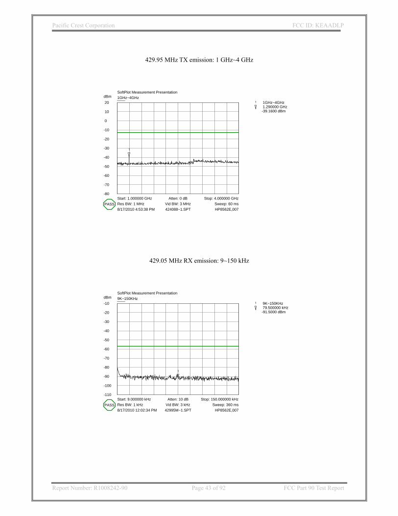
429.95 MHz TX emission: 1 GHz~4 GHz
dBm 20
10
0
-10
-20
-30
-40
-50
-60
-70
-80
SoftPlot Measurement Presentation1GHz~4GHz
Start: 1.000000 GHz Stop: 4.000000 GHzAtten: 0 dBRes BW: 1 MHz Vid BW: 3 MHz Sweep: 60 ms8/17/2010 4:53:38 PM HP8562E,007424088~1.SPT
PASS
1
1 1GHz~4GHz 1.290000 GHz-39.1600 dBm
429.05 MHz RX emission: 9~150 kHz
dBm-10
-20
-30
-40
-50
-60
-70
-80
-90
-100
-110
SoftPlot Measurement Presentation9K~150KHz
Start: 9.000000 kHz Stop: 150.000000 kHzAtten: 10 dBRes BW: 1 kHz Vid BW: 3 kHz Sweep: 360 ms8/17/2010 12:02:34 PM HP8562E,00742995M~1.SPT
PASS
1
1 9K~150KHz 79.500000 kHz-91.5000 dBm

Pacific Crest Corporation FCC ID: KEAADLP
Report Number: R1008242-90 Page 44 of 92 FCC Part 90 Test Report
429.05 MHz RX emission: 150 kHz~30 MHz
dBm-10
-20
-30
-40
-50
-60
-70
-80
-90
-100
-110
SoftPlot Measurement Presentation150KHz~30MHz
Start: 150.000000 kHz Stop: 30.000000 MHzAtten: 10 dBRes BW: 10 kHz Vid BW: 30 kHz Sweep: 750 ms8/17/2010 11:58:04 AM HP8562E,00742995M~2.SPT
PASS
1
1 150KHz~30MHz 15.075000 MHz-88.1600 dBm
429.95 MHz RX emission: 30 MHz~1 GHz
dBm-10
-20
-30
-40
-50
-60
-70
-80
-90
-100
-110
SoftPlot Measurement Presentation30MHz~1GHz
Start: 30.000000 MHz Stop: 1.000000 GHzAtten: 10 dBRes BW: 100 kHz Vid BW: 300 kHz Sweep: 250 ms8/17/2010 12:06:08 PM HP8562E,00742995M~3.SPT
PASS
1
1 30MHz~1GHz 448.716667 MHz-80.5000 dBm
Pacific Crest Corporation FCC ID: KEAADLP
Report Number: R1008242-90 Page 45 of 92 FCC Part 90 Test Report
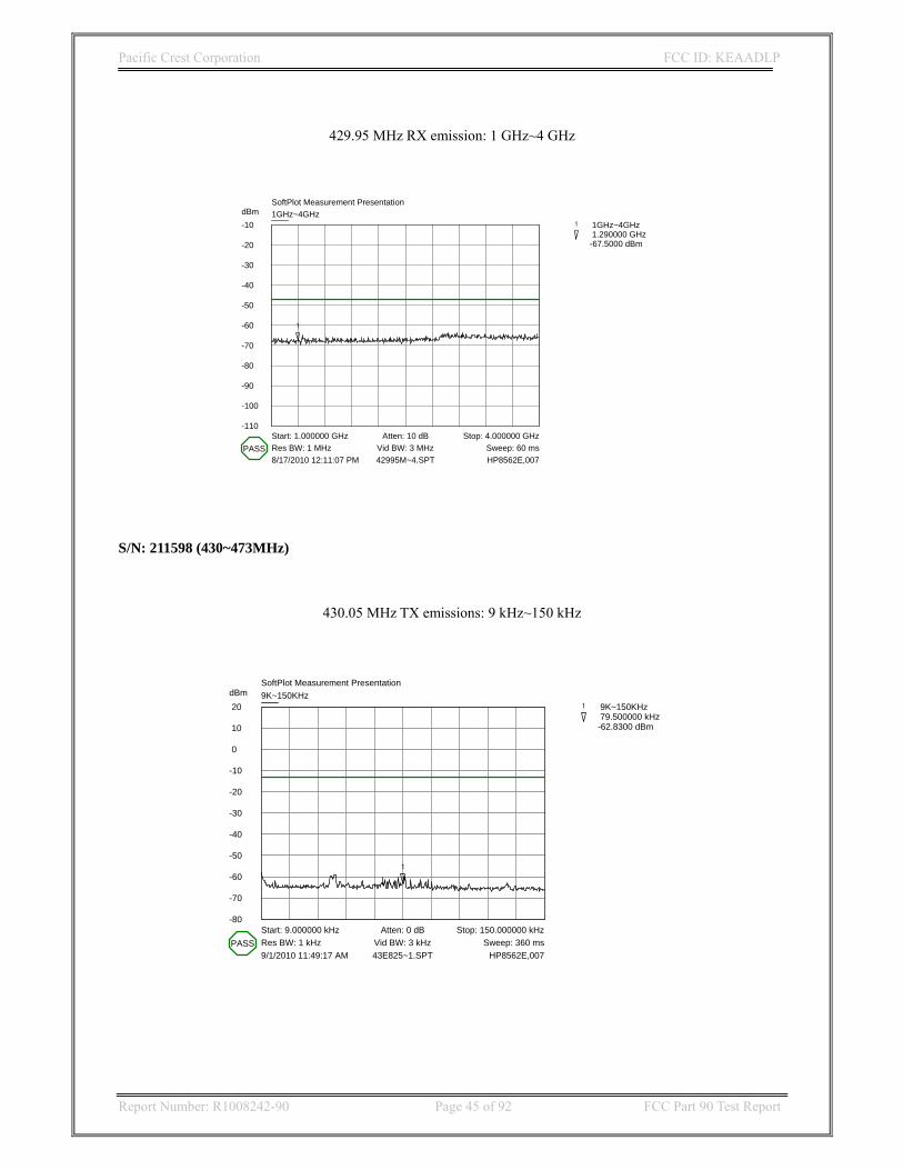
429.95 MHz RX emission: 1 GHz~4 GHz
dBm-10
-20
-30
-40
-50
-60
-70
-80
-90
-100
-110
SoftPlot Measurement Presentation1GHz~4GHz
Start: 1.000000 GHz Stop: 4.000000 GHzAtten: 10 dBRes BW: 1 MHz Vid BW: 3 MHz Sweep: 60 ms8/17/2010 12:11:07 PM HP8562E,00742995M~4.SPT
PASS
1
1 1GHz~4GHz 1.290000 GHz-67.5000 dBm
S/N: 211598 (430~473MHz)
430.05 MHz TX emissions: 9 kHz~150 kHz
dBm 20
10
0
-10
-20
-30
-40
-50
-60
-70
-80
SoftPlot Measurement Presentation9K~150KHz
Start: 9.000000 kHz Stop: 150.000000 kHzAtten: 0 dBRes BW: 1 kHz Vid BW: 3 kHz Sweep: 360 ms9/1/2010 11:49:17 AM HP8562E,00743E825~1.SPT
PASS
1
1 9K~150KHz 79.500000 kHz-62.8300 dBm

Pacific Crest Corporation FCC ID: KEAADLP
Report Number: R1008242-90 Page 46 of 92 FCC Part 90 Test Report
430.05 MHz TX emission: 150 kHz~30 MHz
dBm 20
10
0
-10
-20
-30
-40
-50
-60
-70
-80
SoftPlot Measurement Presentation150KHz~30MHz
Start: 150.000000 kHz Stop: 30.000000 MHzAtten: 0 dBRes BW: 10 kHz Vid BW: 30 kHz Sweep: 750 ms7/22/2010 3:54:19 PM HP8562E,007435B43~1.SPT
PASS
1
1 150KHz~30MHz 15.075000 MHz-62.3300 dBm
430.05 MHz TX emission: 30 MHz~1 GHz (Notch filter is needed to reject carrier)
dBm 20
10
0
-10
-20
-30
-40
-50
-60
-70
-80
SoftPlot Measurement Presentation30MHz~1GHz
Start: 30.000000 MHz Stop: 1.000000 GHzAtten: 0 dBRes BW: 100 kHz Vid BW: 300 kHz Sweep: 250 ms7/22/2010 4:42:26 PM HP8562E,007FCC430~1.SPT
1
1 30MHz~1GHz 448.716667 MHz-56.5000 dBm
2
2 30MHz~1GHz 429.316667 MHz 8.3400 dBm

Pacific Crest Corporation FCC ID: KEAADLP
Report Number: R1008242-90 Page 47 of 92 FCC Part 90 Test Report
430.05 MHz TX emission: 1 GHz~4 GHz
dBm 20
10
0
-10
-20
-30
-40
-50
-60
-70
-80
SoftPlot Measurement Presentation1GHz~4GHz
Start: 1.000000 GHz Stop: 4.000000 GHzAtten: 0 dBRes BW: 1 MHz Vid BW: 3 MHz Sweep: 60 ms7/22/2010 4:27:06 PM HP8562E,00743A04D~1.SPT
PASS
1
1 1GHz~4GHz 1.290000 GHz-37.0000 dBm
2
2 1GHz~4GHz 3.090000 GHz-43.1600 dBm
430.05 MHz RX emission: 9 kHz~150 kHz
dBm-10
-20
-30
-40
-50
-60
-70
-80
-90
-100
-110
SoftPlot Measurement Presentation9K~150KHz
Start: 9.000000 kHz Stop: 150.000000 kHzAtten: 0 dBRes BW: 1 kHz Vid BW: 3 kHz Sweep: 360 ms7/22/2010 2:58:56 PM HP8562E,00743005M~1.SPT
PASS
1
1 9K~150KHz 79.500000 kHz-98.1600 dBm

Pacific Crest Corporation FCC ID: KEAADLP
Report Number: R1008242-90 Page 48 of 92 FCC Part 90 Test Report
430.05 MHz RX emission: 150 kHz~30 MHz
dBm-10
-20
-30
-40
-50
-60
-70
-80
-90
-100
-110
SoftPlot Measurement Presentation150KHz~30MHz
Start: 150.000000 kHz Stop: 30.000000 MHzAtten: 0 dBRes BW: 10 kHz Vid BW: 30 kHz Sweep: 750 ms7/22/2010 3:07:50 PM HP8562E,00743005M~2.SPT
PASS
1
1 150KHz~30MHz 15.075000 MHz-92.5000 dBm
430.05 MHz RX emission: 30 MHz~1 GHz
dBm-10
-20
-30
-40
-50
-60
-70
-80
-90
-100
-110
SoftPlot Measurement Presentation30MHz~1GHz
Start: 30.000000 MHz Stop: 1.000000 GHzAtten: 0 dBRes BW: 100 kHz Vid BW: 300 kHz Sweep: 250 ms7/22/2010 3:11:48 PM HP8562E,00743005M~3.SPT
PASS
1
1 30MHz~1GHz 448.716667 MHz-86.0000 dBm
Pacific Crest Corporation FCC ID: KEAADLP
Report Number: R1008242-90 Page 49 of 92 FCC Part 90 Test Report
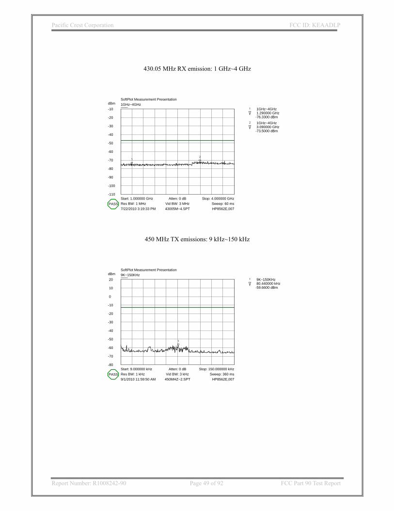
430.05 MHz RX emission: 1 GHz~4 GHz
dBm-10
-20
-30
-40
-50
-60
-70
-80
-90
-100
-110
SoftPlot Measurement Presentation1GHz~4GHz
Start: 1.000000 GHz Stop: 4.000000 GHzAtten: 0 dBRes BW: 1 MHz Vid BW: 3 MHz Sweep: 60 ms7/22/2010 3:19:33 PM HP8562E,00743005M~4.SPT
PASS
1
1 1GHz~4GHz 1.290000 GHz-76.3300 dBm
2
2 1GHz~4GHz 3.090000 GHz-73.5000 dBm
450 MHz TX emissions: 9 kHz~150 kHz
dBm 20
10
0
-10
-20
-30
-40
-50
-60
-70
-80
SoftPlot Measurement Presentation9K~150KHz
Start: 9.000000 kHz Stop: 150.000000 kHzAtten: 0 dBRes BW: 1 kHz Vid BW: 3 kHz Sweep: 360 ms9/1/2010 11:59:50 AM HP8562E,007450MHZ~2.SPT
PASS
1
1 9K~150KHz 80.440000 kHz-59.6600 dBm
Pacific Crest Corporation FCC ID: KEAADLP
Report Number: R1008242-90 Page 50 of 92 FCC Part 90 Test Report
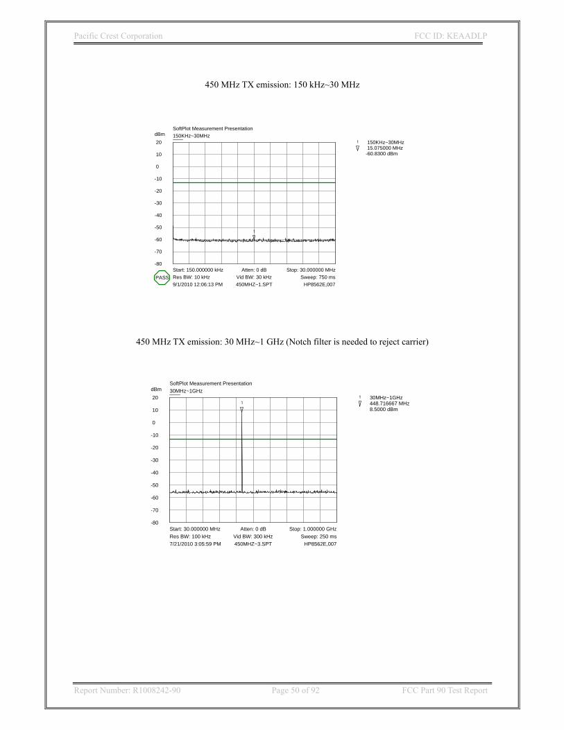
450 MHz TX emission: 150 kHz~30 MHz
dBm 20
10
0
-10
-20
-30
-40
-50
-60
-70
-80
SoftPlot Measurement Presentation150KHz~30MHz
Start: 150.000000 kHz Stop: 30.000000 MHzAtten: 0 dBRes BW: 10 kHz Vid BW: 30 kHz Sweep: 750 ms9/1/2010 12:06:13 PM HP8562E,007450MHZ~1.SPT
PASS
1
1 150KHz~30MHz 15.075000 MHz-60.8300 dBm
450 MHz TX emission: 30 MHz~1 GHz (Notch filter is needed to reject carrier)
dBm 20
10
0
-10
-20
-30
-40
-50
-60
-70
-80
SoftPlot Measurement Presentation30MHz~1GHz
Start: 30.000000 MHz Stop: 1.000000 GHzAtten: 0 dBRes BW: 100 kHz Vid BW: 300 kHz Sweep: 250 ms7/21/2010 3:05:59 PM HP8562E,007450MHZ~3.SPT
11 30MHz~1GHz
448.716667 MHz 8.5000 dBm
Pacific Crest Corporation FCC ID: KEAADLP
Report Number: R1008242-90 Page 51 of 92 FCC Part 90 Test Report
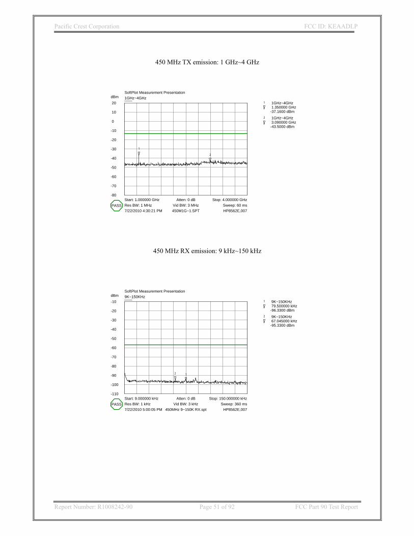
450 MHz TX emission: 1 GHz~4 GHz
dBm 20
10
0
-10
-20
-30
-40
-50
-60
-70
-80
SoftPlot Measurement Presentation1GHz~4GHz
Start: 1.000000 GHz Stop: 4.000000 GHzAtten: 0 dBRes BW: 1 MHz Vid BW: 3 MHz Sweep: 60 ms7/22/2010 4:30:21 PM HP8562E,007450M1G~1.SPT
PASS
1
1 1GHz~4GHz 1.350000 GHz-37.1600 dBm
2
2 1GHz~4GHz 3.090000 GHz-43.5000 dBm
450 MHz RX emission: 9 kHz~150 kHz
dBm-10
-20
-30
-40
-50
-60
-70
-80
-90
-100
-110
SoftPlot Measurement Presentation9K~150KHz
Start: 9.000000 kHz Stop: 150.000000 kHzAtten: 0 dBRes BW: 1 kHz Vid BW: 3 kHz Sweep: 360 ms7/22/2010 5:00:05 PM HP8562E,007450MHz 9~150K RX.spt
PASS
1
1 9K~150KHz 79.500000 kHz-96.3300 dBm
2
2 9K~150KHz 67.045000 kHz-95.3300 dBm
Pacific Crest Corporation FCC ID: KEAADLP
Report Number: R1008242-90 Page 52 of 92 FCC Part 90 Test Report
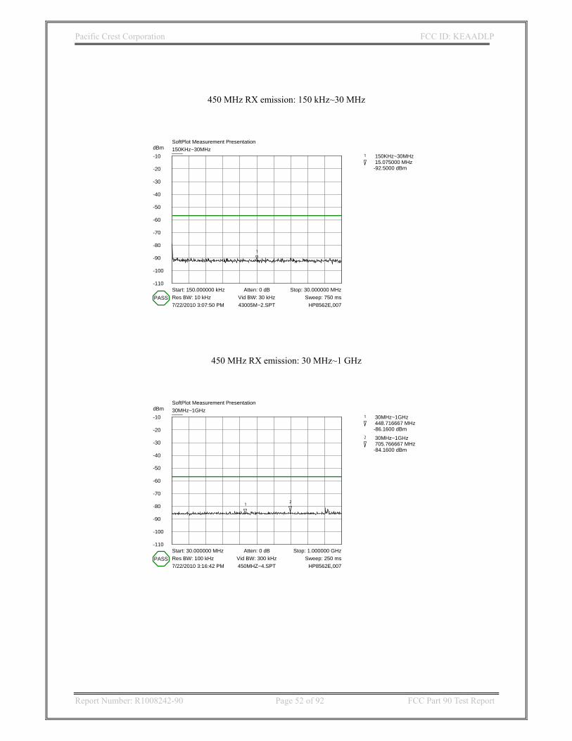
450 MHz RX emission: 150 kHz~30 MHz
dBm-10
-20
-30
-40
-50
-60
-70
-80
-90
-100
-110
SoftPlot Measurement Presentation150KHz~30MHz
Start: 150.000000 kHz Stop: 30.000000 MHzAtten: 0 dBRes BW: 10 kHz Vid BW: 30 kHz Sweep: 750 ms7/22/2010 3:07:50 PM HP8562E,00743005M~2.SPT
PASS
1
1 150KHz~30MHz 15.075000 MHz-92.5000 dBm
450 MHz RX emission: 30 MHz~1 GHz
dBm-10
-20
-30
-40
-50
-60
-70
-80
-90
-100
-110
SoftPlot Measurement Presentation30MHz~1GHz
Start: 30.000000 MHz Stop: 1.000000 GHzAtten: 0 dBRes BW: 100 kHz Vid BW: 300 kHz Sweep: 250 ms7/22/2010 3:16:42 PM HP8562E,007450MHZ~4.SPT
PASS
1
1 30MHz~1GHz 448.716667 MHz-86.1600 dBm
2
2 30MHz~1GHz 705.766667 MHz-84.1600 dBm
Pacific Crest Corporation FCC ID: KEAADLP
Report Number: R1008242-90 Page 53 of 92 FCC Part 90 Test Report
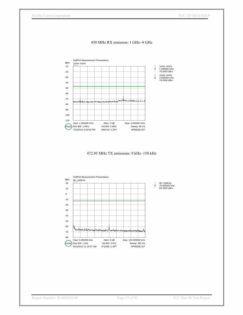
450 MHz RX emission: 1 GHz~4 GHz
dBm-10
-20
-30
-40
-50
-60
-70
-80
-90
-100
-110
SoftPlot Measurement Presentation1GHz~4GHz
Start: 1.000000 GHz Stop: 4.000000 GHzAtten: 0 dBRes BW: 1 MHz Vid BW: 3 MHz Sweep: 60 ms7/22/2010 3:20:53 PM HP8562E,007459CA0~1.SPT
PASS
1
1 1GHz~4GHz 1.290000 GHz-76.8300 dBm
2
2 1GHz~4GHz 3.090000 GHz-74.0000 dBm
472.95 MHz TX emissions: 9 kHz~150 kHz
dBm 20
10
0
-10
-20
-30
-40
-50
-60
-70
-80
SoftPlot Measurement Presentation9K~150KHz
Start: 9.000000 kHz Stop: 150.000000 kHzAtten: 0 dBRes BW: 1 kHz Vid BW: 3 kHz Sweep: 360 ms9/14/2010 11:19:57 AM HP8562E,007471AE6~1.SPT
PASS
1
1 9K~150KHz 79.500000 kHz-65.3300 dBm

Pacific Crest Corporation FCC ID: KEAADLP
Report Number: R1008242-90 Page 54 of 92 FCC Part 90 Test Report
472.95 MHz TX emission: 150 kHz~30 MHz
dBm 20
10
0
-10
-20
-30
-40
-50
-60
-70
-80
SoftPlot Measurement Presentation150KHz~30MHz
Start: 150.000000 kHz Stop: 30.000000 MHzAtten: 0 dBRes BW: 10 kHz Vid BW: 30 kHz Sweep: 750 ms9/14/2010 11:24:46 AM HP8562E,007472193~1.SPT
PASS
1
1 150KHz~30MHz 23.084750 MHz-51.0000 dBm
2
2 150KHz~30MHz 13.781500 MHz-61.1600 dBm
472.95 MHz TX emission: 30 MHz~1 GHz (Notch filter is needed to reject carrier)
dBm 20
10
0
-10
-20
-30
-40
-50
-60
-70
-80
SoftPlot Measurement Presentation30MHz~1GHz
Start: 30.000000 MHz Stop: 1.000000 GHzAtten: 0 dBRes BW: 100 kHz Vid BW: 300 kHz Sweep: 250 ms9/14/2010 12:45:04 PM HP8562E,007478D2C~1.SPT
1
1 30MHz~1GHz 409.916667 MHz-57.1600 dBm
2
2 30MHz~1GHz 515.000000 MHz-56.5000 dBm
3
3 30MHz~1GHz 472.966667 MHz 11.5000 dBm

Pacific Crest Corporation FCC ID: KEAADLP
Report Number: R1008242-90 Page 55 of 92 FCC Part 90 Test Report
472.95 MHz TX emission: 1 GHz~4 GHz
dBm 20
10
0
-10
-20
-30
-40
-50
-60
-70
-80
SoftPlot Measurement Presentation1GHz~4GHz
Start: 1.000000 GHz Stop: 4.000000 GHzAtten: 0 dBRes BW: 1 MHz Vid BW: 3 MHz Sweep: 60 ms9/14/2010 12:48:36 PM HP8562E,00747DEDB~1.SPT
PASS
1
1 1GHz~4GHz 1.290000 GHz-46.1600 dBm
472.95 MHz RX emission: 9 kHz~150 kHz
dBm-10
-20
-30
-40
-50
-60
-70
-80
-90
-100
-110
SoftPlot Measurement Presentation9K~150KHz
Start: 9.000000 kHz Stop: 150.000000 kHzAtten: 0 dBRes BW: 1 kHz Vid BW: 3 kHz Sweep: 360 ms9/14/2010 10:58:02 AM HP8562E,00747295M~1.SPT
PASS
1
1 9K~150KHz 79.500000 kHz-96.1600 dBm

Pacific Crest Corporation FCC ID: KEAADLP
Report Number: R1008242-90 Page 56 of 92 FCC Part 90 Test Report
472.95 MHz RX emission: 150 kHz~30 MHz
dBm-10
-20
-30
-40
-50
-60
-70
-80
-90
-100
-110
SoftPlot Measurement Presentation150KHz~30MHz
Start: 150.000000 kHz Stop: 30.000000 MHzAtten: 0 dBRes BW: 10 kHz Vid BW: 30 kHz Sweep: 750 ms9/14/2010 11:00:02 AM HP8562E,00747295M~2.SPT
PASS
1
1 150KHz~30MHz 15.075000 MHz-91.3300 dBm
472.95 MHz RX emission: 30 MHz~1 GHz
dBm-10
-20
-30
-40
-50
-60
-70
-80
-90
-100
-110
SoftPlot Measurement Presentation30MHz~1GHz
Start: 30.000000 MHz Stop: 1.000000 GHzAtten: 0 dBRes BW: 100 kHz Vid BW: 300 kHz Sweep: 250 ms9/14/2010 11:03:11 AM HP8562E,00747295M~3.SPT
PASS
1
1 30MHz~1GHz 448.716667 MHz-85.6600 dBm
2
2 30MHz~1GHz 472.966667 MHz-87.1600 dBm

Pacific Crest Corporation FCC ID: KEAADLP
Report Number: R1008242-90 Page 57 of 92 FCC Part 90 Test Report
472.95 MHz RX emission: 1 GHz~4 GHz
dBm-10
-20
-30
-40
-50
-60
-70
-80
-90
-100
-110
SoftPlot Measurement Presentation1GHz~4GHz
Start: 1.000000 GHz Stop: 4.000000 GHzAtten: 0 dBRes BW: 1 MHz Vid BW: 3 MHz Sweep: 60 ms9/14/2010 11:06:50 AM HP8562E,00747295M~4.SPT
PASS
1
1 1GHz~4GHz 1.290000 GHz-77.5000 dBm

Pacific Crest Corporation FCC ID: KEAADLP
Report Number: R1008242-90 Page 58 of 92 FCC Part 90 Test Report
9 FCC §2.1053 & §90.210 - Radiated Spurious Emissions
9.1 Applicable Standard FCC §2.1053 (a) Measurements shall be made to detect spurious emissions that may be radiated directly from the cabinet, control circuits, power leads, or intermediate circuit elements under normal conditions of installation and operation. Curves or equivalent data shall be supplied showing the magnitude of each harmonic and other spurious emission. For this test, single sideband, independent sideband, and controlled carrier transmitters shall be modulated under the conditions specified in paragraph (c) of §2.1049, as appropriate and §90.210(b),(d): Except as indicated elsewhere in this part, transmitters used in the radio services governed by this part must comply with the emission masks outlined in this section. Unless otherwise stated, per paragraphs (d)(4), (e)(4), and (m) of this section, measurements of emission power can be expressed in either peak or average values provided that emission powers are expressed with the same parameters used to specify the unmodulated transmitter carrier power. For transmitters that do not produce a full power unmodulated carrier, reference to the unmodulated transmitter carrier power refers to the total power contained in the channel bandwidth. Unless indicated elsewhere in this part, the table in this section specifies the emission masks for equipment operating in the frequency bands governed under this part. 9.2 Test Procedure TIA-603-C §2.2.12 The transmitter was placed on a wooden turntable, and it was transmitting into a non-radiating load which was also placed on the turntable. The measurement antenna was placed at a distance of 3 meters from the EUT. During the tests, the antenna height and polarization as well as EUT azimuth were varied in order to identify the maximum level of emissions from the EUT. The test was performed by placing the EUT on 3-orthogonal axis. The frequency range up to tenth harmonic of the fundamental frequency was investigated. Remove the EUT and replace it with substitution antenna. A signal generator was connected to the substitution antenna by a non-radiating cable. The absolute levels of the spurious emissions were measured by the substitution. Spurious emissions in dB = 10 log (TX power in Watts/0.001) – the absolute level Spurious attenuation limit in dB = 43 + 10 Log10 (power out in Watts) for EUT with a 25 KHz channel bandwidth. Spurious attenuation limit in dB = 50 + 10 Log10 (power out in Watts) for EUT with a 12.5 KHz channel bandwidth.

Pacific Crest Corporation FCC ID: KEAADLP
Report Number: R1008242-90 Page 59 of 92 FCC Part 90 Test Report
9.3 Test Equipment List and Details
Manufacturer Description Model Serial Number Calibration Date
Rohde & Schwarz EMI Test Receiver ESCI
1166.5950K03 100337 2010-03-24
Agilent Spectrum Analyzer E4440A US45303156 2010-08-09
Sunol Science Corp System Controller SC99V 122303-1 N/R
Sunol Science Corp Combination Antenna JB3 A0020106-2 2010-08-06
Hewlett Packard Pre amplifier 8447D 2944A06639 2010-06-18
A.R.A Inc Horn antenna DRG-1181A 1132 2009-10-27
Mini-Circuits Pre Amplifier ZVA-183-S 570400946 2010-05-10
Statement of Traceability: BACL attests that all calibrations have been performed per the NVLAP requirements, traceable to NIST.
9.4 Test Setup Styrofoam 70 cm above table
EUT
Antenna port terminated with 50 ohm load
AC Power
Laptop
Serial Cable

Pacific Crest Corporation FCC ID: KEAADLP
Report Number: R1008242-90 Page 60 of 92 FCC Part 90 Test Report
9.5 Test Environmental Conditions
Temperature: 19~25 °C Relative Humidity: 50~54 %
ATM Pressure: 100.9~101.2kPa
The testing was performed by Jerry Huang on 2010-10-11~2010-10-14
9.6 Test Result 390-430 MHz Band SN: 10370002
Middle Channel (Channel spacing 12.5 kHz)
Indicated Test Antenna Substituted
Frequency
(MHz)
S.A.
Amp.
(dBuV)
Azimuth
(degrees) Height
(cm)
Polar
(H/V)
Frequency
(MHz)
Level
(dBm)
Ant.
Cord.
(dBi)
Cable
Loss
(dB)
Absolute
Level
(dBm)
Limit
(dBm)
Margin
(dB)
819.7 42.37 219 175 H 819.7 -39.71 0 0.66 -40.37 -20 -20.37
819.7 41.73 184 196 V 819.7 -38.69 0 0.66 -39.35 -20 -19.35
1229.55 64.86 121 149 V 1229.55 -38.31 6.522 0.83 -32.618 -20 -12.618
1229.55 66.15 258 147 H 1229.55 -37.02 6.522 0.83 -31.328 -20 -11.328
1639.4 53.54 269 151 H 1639.4 -49.09 8.749 1 -41.341 -20 -21.341
1639.4 49.97 84 127 V 1639.4 -51.97 8.749 1 -44.221 -20 -24.221
2049.25 62.47 148 153 H 2049.25 -39.23 8.606 1.32 -31.944 -20 -11.944
2049.25 63.51 194 149 V 2049.25 -38.19 8.606 1.32 -30.904 -20 -10.904
2459.1 48.95 112 238 H 2459.1 -49.05 9.356 1.34 -41.034 -20 -21.034
2459.1 50.48 277 149 V 2459.1 -47.13 9.356 1.34 -39.114 -20 -19.114
2868.95 51 216 180 H 2868.95 -45.6 10.332 1.34 -36.608 -20 -16.608
2868.95 55.7 183 142 V 2868.95 -41.09 10.332 1.34 -32.098 -20 -12.098
3278.8 54.45 248 109 H 3278.8 -42.02 9.846 1.32 -33.494 -20 -13.494
3278.8 52.27 218 172 V 3278.8 -43.93 9.846 1.32 -35.404 -20 -15.404
4098.5 46.99 224 166 H 4098.5 -49.31 10.62 1.83 -40.52 -20 -20.52
4098.5 48.39 215 131 V 4098.5 -47.73 10.62 1.83 -38.94 -20 -18.94
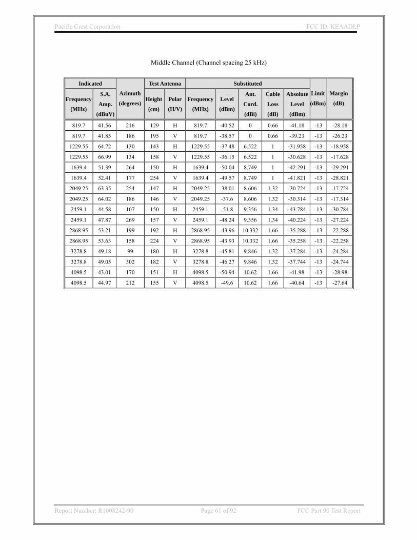
Pacific Crest Corporation FCC ID: KEAADLP
Report Number: R1008242-90 Page 61 of 92 FCC Part 90 Test Report
Middle Channel (Channel spacing 25 kHz)
Indicated Test Antenna Substituted
Frequency
(MHz)
S.A.
Amp.
(dBuV)
Azimuth
(degrees) Height
(cm)
Polar
(H/V)
Frequency
(MHz)
Level
(dBm)
Ant.
Cord.
(dBi)
Cable
Loss
(dB)
Absolute
Level
(dBm)
Limit
(dBm)
Margin
(dB)
819.7 41.56 216 129 H 819.7 -40.52 0 0.66 -41.18 -13 -28.18
819.7 41.85 186 195 V 819.7 -38.57 0 0.66 -39.23 -13 -26.23
1229.55 64.72 130 143 H 1229.55 -37.48 6.522 1 -31.958 -13 -18.958
1229.55 66.99 134 158 V 1229.55 -36.15 6.522 1 -30.628 -13 -17.628
1639.4 51.39 264 150 H 1639.4 -50.04 8.749 1 -42.291 -13 -29.291
1639.4 52.41 177 254 V 1639.4 -49.57 8.749 1 -41.821 -13 -28.821
2049.25 63.35 254 147 H 2049.25 -38.01 8.606 1.32 -30.724 -13 -17.724
2049.25 64.02 186 146 V 2049.25 -37.6 8.606 1.32 -30.314 -13 -17.314
2459.1 44.58 107 150 H 2459.1 -51.8 9.356 1.34 -43.784 -13 -30.784
2459.1 47.87 269 157 V 2459.1 -48.24 9.356 1.34 -40.224 -13 -27.224
2868.95 53.21 199 192 H 2868.95 -43.96 10.332 1.66 -35.288 -13 -22.288
2868.95 53.63 158 224 V 2868.95 -43.93 10.332 1.66 -35.258 -13 -22.258
3278.8 49.18 99 180 H 3278.8 -45.81 9.846 1.32 -37.284 -13 -24.284
3278.8 49.05 302 182 V 3278.8 -46.27 9.846 1.32 -37.744 -13 -24.744
4098.5 43.01 170 151 H 4098.5 -50.94 10.62 1.66 -41.98 -13 -28.98
4098.5 44.97 212 155 V 4098.5 -49.6 10.62 1.66 -40.64 -13 -27.64

Pacific Crest Corporation FCC ID: KEAADLP
Report Number: R1008242-90 Page 62 of 92 FCC Part 90 Test Report
430~ 473 MHz Band SN: 10370005
Middle Channel (Channel spacing 12.5 kHz)
Indicated Test Antenna Substituted
Frequency
(MHz)
S.A.
Amp.
(dBuV)
Azimuth
(degrees) Height
(cm)
Polar
(H/V)
Frequency
(MHz)
Level
(dBm)
Ant.
Cord.
(dBi)
Cable
Loss
(dB)
Absolute
Level
(dBm)
Limit
(dBm)
Margin
(dB)
432.6 37.92 262 139 H 432.6 -65.9 0 0.66 -66.56 -20 -46.56
432.6 35.84 176 150 V 432.6 -65.12 0 0.66 -65.78 -20 -45.78
899.7 41.33 278 169 H 899.7 -52.98 0 0.66 -53.64 -20 -33.64
899.7 38.37 280 177 V 899.7 -53.9 0 0.66 -54.56 -20 -34.56
1349.55 67.53 133 147 H 1349.55 -41.88 7.625 0.83 -35.085 -20 -15.085
1349.55 71.56 172 221 V 1349.55 -37.48 7.625 0.83 -30.685 -20 -10.685
1799.4 64.21 232 162 H 1799.4 -44.77 9.583 1 -36.187 -20 -16.187
1799.4 66.69 4 206 V 1799.4 -42.23 9.583 1 -33.647 -20 -13.647
2249.25 64.43 330 148 H 2249.25 -43.03 9.06 1 -34.97 -20 -14.97
2249.25 65.33 266 152 V 2249.25 -41.64 9.06 1 -33.58 -20 -13.58
2699.1 59.32 51 183 H 2699.1 -45.59 9.272 1.34 -37.658 -20 -17.658
2699.1 62.95 199 119 V 2699.1 -41.58 9.272 1.34 -33.648 -20 -13.648
3148.95 56.38 127 148 H 3148.95 -47.27 9.476 1.32 -39.114 -20 -19.114
3148.95 59.21 203 107 V 3148.95 -44.24 9.476 1.32 -36.084 -20 -16.084
3598.8 48.72 252 267 H 3598.8 -52.67 10.082 1.83 -44.418 -20 -24.418
3598.8 50.15 299 131 V 3598.8 -51.78 10.082 1.83 -43.528 -20 -23.528
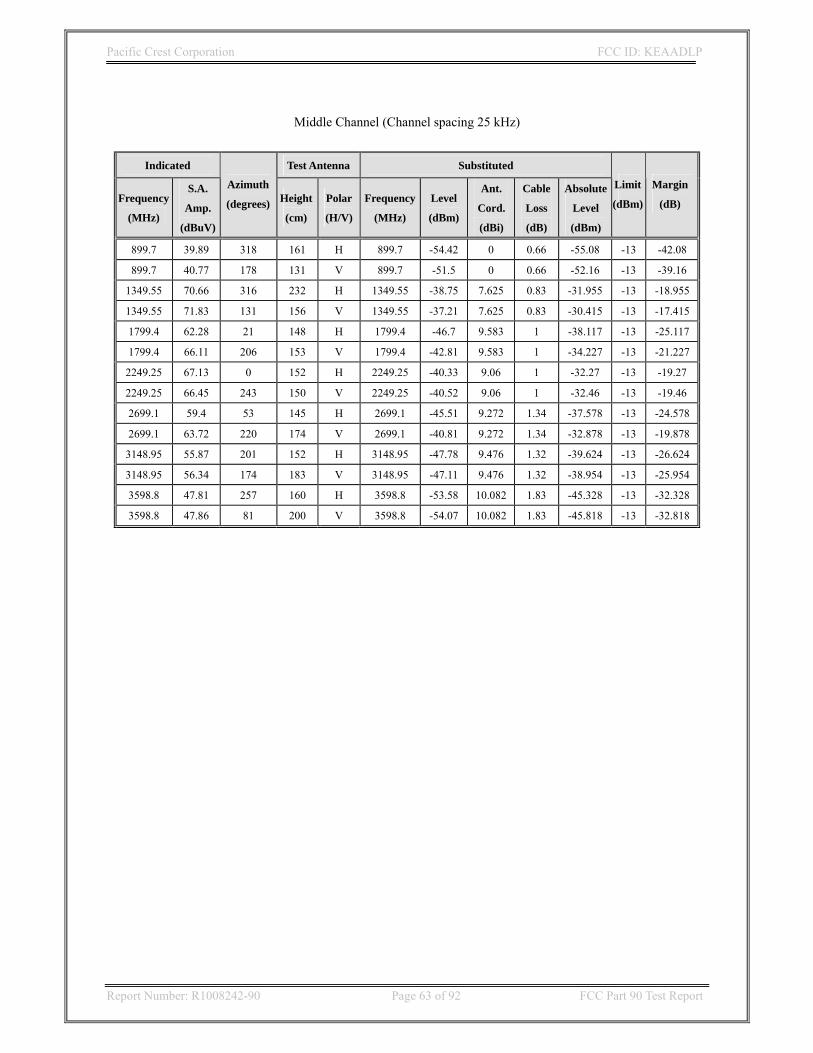
Pacific Crest Corporation FCC ID: KEAADLP
Report Number: R1008242-90 Page 63 of 92 FCC Part 90 Test Report
Middle Channel (Channel spacing 25 kHz)
Indicated Test Antenna Substituted
Frequency
(MHz)
S.A.
Amp.
(dBuV)
Azimuth
(degrees) Height
(cm)
Polar
(H/V)
Frequency
(MHz)
Level
(dBm)
Ant.
Cord.
(dBi)
Cable
Loss
(dB)
Absolute
Level
(dBm)
Limit
(dBm)
Margin
(dB)
899.7 39.89 318 161 H 899.7 -54.42 0 0.66 -55.08 -13 -42.08
899.7 40.77 178 131 V 899.7 -51.5 0 0.66 -52.16 -13 -39.16
1349.55 70.66 316 232 H 1349.55 -38.75 7.625 0.83 -31.955 -13 -18.955
1349.55 71.83 131 156 V 1349.55 -37.21 7.625 0.83 -30.415 -13 -17.415
1799.4 62.28 21 148 H 1799.4 -46.7 9.583 1 -38.117 -13 -25.117
1799.4 66.11 206 153 V 1799.4 -42.81 9.583 1 -34.227 -13 -21.227
2249.25 67.13 0 152 H 2249.25 -40.33 9.06 1 -32.27 -13 -19.27
2249.25 66.45 243 150 V 2249.25 -40.52 9.06 1 -32.46 -13 -19.46
2699.1 59.4 53 145 H 2699.1 -45.51 9.272 1.34 -37.578 -13 -24.578
2699.1 63.72 220 174 V 2699.1 -40.81 9.272 1.34 -32.878 -13 -19.878
3148.95 55.87 201 152 H 3148.95 -47.78 9.476 1.32 -39.624 -13 -26.624
3148.95 56.34 174 183 V 3148.95 -47.11 9.476 1.32 -38.954 -13 -25.954
3598.8 47.81 257 160 H 3598.8 -53.58 10.082 1.83 -45.328 -13 -32.328
3598.8 47.86 81 200 V 3598.8 -54.07 10.082 1.83 -45.818 -13 -32.818

Pacific Crest Corporation FCC ID: KEAADLP
Report Number: R1008242-90 Page 64 of 92 FCC Part 90 Test Report
10 FCC §2.1055 & §90.213- Frequency Stability
10.1 Applicable Standard FCC §2.1055 and §90.213 for output power > 2 watts, the limit is 5.0ppm, mobile stations designed to operate with a 12.5 KHz channel bandwidth must have a frequency stability of 2.5 ppm. 10.2 Test Procedure Frequency Stability vs. Temperature: The equipment under test was connected to an external DC power supply and the RF output was connected to a frequency counter (or spectrum analyzer) via feed through attenuators. The EUT was placed inside the temperature chamber. The DC leads and RF output cable exited the chamber through an opening made for the purpose. After the temperature stabilized for approximately 20 minutes, the frequency output was recorded from the counter. Frequency Stability vs. Voltage: An external variable DC power supply was connected to the equipment under test. The voltage was set from 85% to 115% of the nominal value. The output frequency was recorded for each voltage. 10.3 Test Equipment List and Details
Manufacturer Description Model S/N Cal Date
Agilent Spectrum Analyzer 8562EC 3946A00288 12/22/2009
Tenney Temperature Oven Series 942 CL5CHAMBERS N/A
TekPower DC power supply HY3005D N/A N/A
10.4 Test Environment Conditions
Temperature: 20~22 °C Relative Humidity: 70~75 %
ATM Pressure: 100.9~101.2kPa
The testing was performed by Jacinto Amante on 2010-07-27, 2010-09-27

Pacific Crest Corporation FCC ID: KEAADLP
Report Number: R1008242-90 Page 65 of 92 FCC Part 90 Test Report
10.5 Test Results S/N: 211505 (390~430 MHz)
Reference Frequency 390.05 MHz Test Condition Frequency Measure with Time Elapsed
Temperature (OC) Power Supply(Vdc) Freq Error (KHz) ppm Error Result
Frequency vs. Temperature
60 12 0.21 0.54 Compliant
50 12 0.14 0.36 Compliant
40 12 0.05 0.13 Compliant
30 12 0.07 0.18 Compliant
20 12 0.004 0.001 Complaint
10 12 -0.11 -0.28 Compliant
0 12 -0.18 -0.46 Compliant
-10 12 -0.06 -0.15 Compliant
-20 12 -0.008 -0.019 Compliant
-30 12 0.20 0.53 Compliant
Frequency vs. Voltage 20 10.2 0.004 0.001 Compliant
20 13.8 0.004 0.001 Compliant
Reference Frequency 410 MHz Test Condition Frequency Measure with Time Elapsed
Temperature (OC) Power Supply(Vdc) Freq Error (KHz) ppm Error Result
Frequency vs. Temperature
60 12 0.21 0.50 Compliant
50 12 0.14 0.34 Compliant
40 12 0.07 0.16 Compliant
30 12 0.07 0.16 Compliant
20 12 0.005 0.001 Complaint
10 12 -0.11 -0.27 Compliant
0 12 -0.18 -0.45 Compliant
-10 12 -0.06 -0.14 Compliant
-20 12 -0.008 -0.017 Compliant
-30 12 0.15 0.36 Compliant
Frequency vs. Voltage 20 10.2 0.005 0.001 Compliant
20 13.8 0.005 0.001 Compliant

Pacific Crest Corporation FCC ID: KEAADLP
Report Number: R1008242-90 Page 66 of 92 FCC Part 90 Test Report
Reference Frequency 429.95 MHz Test Condition Frequency Measure with Time Elapsed
Temperature (OC) Power Supply(Vdc) Freq Error (KHz) ppm Error Result
Frequency vs. Temperature
60 12 0.24 0.56 Compliant
50 12 0.18 0.42 Compliant
40 12 0.09 0.21 Compliant
30 12 0.08 0.20 Compliant
20 12 0.048 0.11 Complaint
10 12 -0.15 -0.35 Compliant
0 12 -0.20 -0.47 Compliant
-10 12 -0.04 -0.09 Compliant
-20 12 -0.03 -0.08 Compliant
-30 12 0.17 0.41 Compliant
Frequency vs. Voltage 20 10.2 0.048 0.11 Compliant
20 13.8 0.048 0.11 Compliant
S/N: 211598 (430~473 MHz)
Reference Frequency 430.05 MHz Test Condition Frequency Measure with Time Elapsed
Temperature (OC) Power Supply(Vdc) Freq Error (KHz) ppm Error Result
Frequency vs. Temperature
60 12 -0.17 -0.39 Compliant
50 12 -0.15 -0.34 Compliant
40 12 -0.14 -0.32 Compliant
30 12 -0.08 -0.18 Compliant
20 12 0.025 0.05 Complaint
10 12 0.046 0.10 Compliant
0 12 0.14 0.32 Compliant
-10 12 0.20 0.46 Compliant
-20 12 0.22 0.51 Compliant
-30 12 0.32 0.74 Compliant
Frequency vs. Voltage 20 10.2 0.025 0.05 Compliant
20 13.8 0.025 0.05 Compliant

Pacific Crest Corporation FCC ID: KEAADLP
Report Number: R1008242-90 Page 67 of 92 FCC Part 90 Test Report
Reference Frequency 450 MHz Test Condition Frequency Measure with Time Elapsed
Temperature (OC) Power Supply(Vdc) Freq Error (KHz) ppm Error Result
Frequency vs. Temperature
60 12 -0.14 -0.31 Compliant
50 12 -0.15 -0.33 Compliant
40 12 -0.15 -0.33 Compliant
30 12 -0.09 -0.20 Compliant
20 12 0.024 0.05 Complaint
10 12 0.06 0.13 Compliant
0 12 0.13 0.29 Compliant
-10 12 0.19 0.42 Compliant
-20 12 0.25 0.56 Compliant
-30 12 0.30 0.67 Compliant
Frequency vs. Voltage 20 10.2 0.024 0.05 Compliant
20 13.8 0.024 0.05 Compliant
Reference Frequency 472.95 MHz Test Condition Frequency Measure with Time Elapsed
Temperature (OC) Power Supply(Vdc) Freq Error (KHz) ppm Error Result
Frequency vs. Temperature
60 12 -0.18 -0.38 Compliant
50 12 -0.15 -0.32 Compliant
40 12 -0.15 -0.32 Compliant
30 12 -0.039 -0.08 Compliant
20 12 0.035 0.07 Complaint
10 12 0.08 0.17 Compliant
0 12 0.19 0.40 Compliant
-10 12 0.27 0.57 Compliant
-20 12 0.21 0.45 Compliant
-30 12 0.40 0.85 Compliant
Frequency vs. Voltage 20 10.2 0.035 0.07 Compliant
20 13.8 0.035 0.07 Compliant

Pacific Crest Corporation FCC ID: KEAADLP
Report Number: R1008242-90 Page 68 of 92 FCC Part 90 Test Report
11 FCC §90.214 – Transient Frequency Behavior
11.1 Standard Applicable FCC §90.214, Transmitters designed to operate in the 150–174 MHz and 421–512 MHz frequency bands must maintain transient frequencies within the maximum frequency difference limits. 11.2 Test Method TIA/EIA-603 2.2.19 11.3 Test Equipment List and Details
Manufacturer Description Model S/N Cal Date
Agilent Spectrum Analyzer 8562EC 3946A00288 12/22/2009
TekPower DC power supply HY3005D N/A N/A
HP RF Communications Test Set 8920A 274652140 12/23/2009
Tectronix Scope TDS 220 B067544 12/23/2009
HP Signal Generator 8648A 3426A00120 12/23/2009
11.4 Test Environment Conditions
Temperature: 20~22 °C Relative Humidity: 70~75 %
ATM Pressure: 100.9~101.2kPa
The testing was performed by Hui Chen on 2010-07-29, 2010-08-05

Pacific Crest Corporation FCC ID: KEAADLP
Report Number: R1008242-90 Page 69 of 92 FCC Part 90 Test Report
11.5 Test Results Transmitter designed to operate in 421-512MHz frequency bands must maintain transient frequencies within the maximum frequency difference limits during the time intervals indicated:
Time Intervals Maximum frequency difference 421 to 512 MHz
Transient frequency behavior for equipment designed to operate on 25 kHz channels
Limit Test Result( for all testing frequencies)
Time Intervals
T1 +/- 25 kHz < +/- 1.25 kHz 10.0 ms T2 +/-12.5 kHz < +/- 1.25 kHz 25.0 ms T3 +/-25 kHz < +/- 1.25 kHz 10.0 ms
Transient frequency behavior for equipment designed to operate on 12.5 kHz channels Limit Test Result
T1 +/-12.5 kHz < +/- 1.25 kHz 10.0 ms T2 +/-6.25 kHz < +/- 1.25 kHz 25.0 ms T3 +/-12.5 kHz < +/- 1.25 kHz 10.0 ms
Ton is the instant when a 1 kHz test signal is completely suppressed, including any capture time due to phasing. T1 is the time period immediately following ton. T2 is the time period immediately following t1. T3 is the time period from the instant when the transmitter is turned off until toff. Toff is the instant when the 1 kHz testing signal starts to rise. During the time from the end of t2 to the beginning of t3, the frequency difference must not exceed the limits specified in §90.213. The allowed limit is equal to the transmitter frequency times its FCC frequency tolerance times+/- 4 display divisions divided by 25 kHz.

Pacific Crest Corporation FCC ID: KEAADLP
Report Number: R1008242-90 Page 70 of 92 FCC Part 90 Test Report
S/N: 211505(390~430 MHz)
1 kHz tone at +/-5 kHz deviation
390.05 MHz turn on transient frequency

Pacific Crest Corporation FCC ID: KEAADLP
Report Number: R1008242-90 Page 71 of 92 FCC Part 90 Test Report
390.05 MHz turn off transient frequency
410 MHz turn on transient frequency

Pacific Crest Corporation FCC ID: KEAADLP
Report Number: R1008242-90 Page 72 of 92 FCC Part 90 Test Report
410 MHz turn off transient frequency
429.95 MHz turn on transient frequency

Pacific Crest Corporation FCC ID: KEAADLP
Report Number: R1008242-90 Page 73 of 92 FCC Part 90 Test Report
429.85 MHz turn off transient frequency
S/N: 211598(430~473 MHz)
1 kHz tone at +/-5 kHz deviation

Pacific Crest Corporation FCC ID: KEAADLP
Report Number: R1008242-90 Page 74 of 92 FCC Part 90 Test Report
430.05 MHz turn on transient frequency
430.05 MHz turn off transient frequency

Pacific Crest Corporation FCC ID: KEAADLP
Report Number: R1008242-90 Page 75 of 92 FCC Part 90 Test Report
450 MHz turn on transient frequency
450 MHz turn off transient frequency

Pacific Crest Corporation FCC ID: KEAADLP
Report Number: R1008242-90 Page 76 of 92 FCC Part 90 Test Report
472.95 MHz turn on transient frequency
472.95 MHz turn off transient frequency