fcc 15.247 dts march 31, 2016 paul hay original document 2.0 august 18, 2016 amanda reed updated...
TRANSCRIPT

p1630036_FCC_Part 15.407_DFS_Rev 2.0
Page 1 of 39
Test Report
Prepared for: Ubiquiti Networks, Inc
Model: LOCOM5
Description: NanoStation M5
Serial Number: N/A
FCC ID: SWX-M5LB IC: 6545A-M5LB
To
FCC Part 15.407 DFS
Date of Issue: August 18, 2016
On the behalf of the applicant: Ubiquiti Networks, Inc 2580 Orchard Parkway San Jose, CA 95131
Attention of: Kevin Forbey, Regulatory Manager
Ph: (408) 942-3085 E-mail: [email protected]
Prepared By Compliance Testing, LLC
1724 S. Nevada Way Mesa, AZ 85204
(480) 926-3100 phone / (480) 926-3598 fax www.compliancetesting.com
Project No: p1630036
Paul Hay
Project Test Engineer
This report may not be reproduced, except in full, without written permission from Compliance Testing. All results contained herein relate only to the sample tested.
p1630036_FCC_Part 15.407_DFS_Rev 2.0
Page 2 of 39
Test Report Revision History
Revision Date Revised By Reason for Revision
1.0 March 31, 2016 Paul Hay Original Document
2.0 August 18, 2016 Amanda Reed Updated phone number on cover page

p1630036_FCC_Part 15.407_DFS_Rev 2.0
Page 3 of 39
Table of Contents
Description Page
Standard Test Conditions Engineering Practices 6
Test Results Summary 10
Conducted Setup for Master with injection at the Master 16
Conducted Setup for Client with injection at the Client 17
Radar Waveform Calibration 18
Channel Loading 22
U-NII Detection Bandwidth 25
Initial CACT 26
Radar Burst at the Beginning of the Channel Availability Check Time 27
Radar Burst at the End of the Channel Availability Check Time 28
Statistical Performance Check 32
See Annex B for Statistical Performance Check results 32
Short Pulse Radar Test Summary 35
Test Equipment Utilized 39

p1630036_FCC_Part 15.407_DFS_Rev 2.0
Page 4 of 39
ILAC / A2LA
Compliance Testing, LLC, has been accredited in accordance with the recognized International Standard ISO/IEC 17025:2005. This accreditation demonstrates technical competence for a defined scope and the operation of a laboratory quality management system (refer to the joint ISO-ILAC-IAF Communiqué dated January 2009).
The tests results contained within this test report all fall within our scope of accreditation, unless noted below. Please refer to http://www.compliancetesting.com/labscope.html for current scope of accreditation. Testing Certificate Number: 2152.01
FCC Site Reg. #349717 IC Site Reg. #2044A-2
Non-accredited tests contained in this report:
N/A
p1630036_FCC_Part 15.407_DFS_Rev 2.0
Page 5 of 39
The applicant has been cautioned as to the following 15.21 - Information to User The user’s manual or instruction manual for an intentional radiator shall caution the user that changes or modifications not expressly approved by the party responsible for compliance could void the user’s authority to operate the equipment. 15.27(a) - Special Accessories Equipment marked to a consumer must be capable of complying with the necessary regulations in the configuration in which the equipment is marketed. Where special accessories, such as shielded cables and/or special connectors are required to enable an unintentional or intentional radiator to comply with the emission limits in this part, the equipment must be marketed with, i.e. shipped and sold with, those special accessories. However, in lieu of shipping or packaging the special accessories with the unintentional or intentional radiator, the responsible party may employ other methods of ensuring that the special accessories are provided to the consumer without an additional charge. Information detailing any alternative method used to supply the special accessories for a grant of equipment authorization or retained in the verification records, as appropriate. The party responsible for the equipment, as detailed in § 2.909 of this chapter, shall ensure that these special accessories are provided with the equipment. The instruction manual for such devices shall include appropriate instructions on the first page of text concerned with the installation of the device that these special accessories must be used with the device. It is the responsibility of the user to use the needed special accessories supplied with the equipment.

p1630036_FCC_Part 15.407_DFS_Rev 2.0
Page 6 of 39
Standard Test Conditions Engineering Practices
Except as noted herein, the following conditions and procedures were observed during the testing: In accordance with ANSI C63.10-2013 and unless otherwise indicated in the specific measurement results, the ambient temperature of the actual EUT was maintained within the range of 10° to 40°C (50° to 104°F) unless the particular equipment requirements specified testing over a different temperature range. Also, unless otherwise indicated, the humidity levels were in the range of 10% to 90% relative humidity. Measurement results, unless otherwise noted, are worst-case measurements.
Environmental Conditions
Temperature (ºC)
Humidity (%)
Pressure (mbar)
20.8 – 21.9 32.7 – 41.2 961.3 – 972.4
EUT Description Model: NSM2/NSM3/NSM365/NSM5/locoM2/locoM5 Description: NanoStation M / NanoStation loco M Firmware: N/A Software: N/A Serial Number: N/A
Accessories: None
Cables: None
Modifications: None
p1630036_FCC_Part 15.407_DFS_Rev 2.0
Page 7 of 39
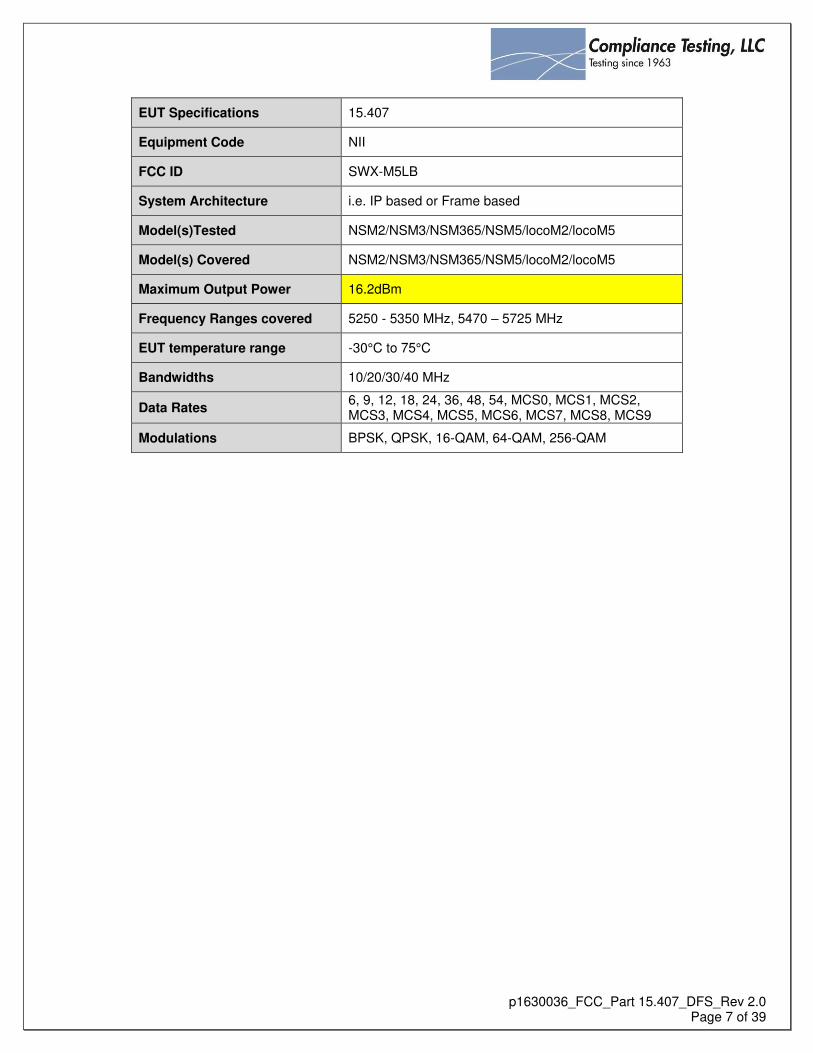
EUT Specifications 15.407
Equipment Code NII
FCC ID SWX-M5LB
System Architecture i.e. IP based or Frame based
Model(s)Tested NSM2/NSM3/NSM365/NSM5/locoM2/locoM5
Model(s) Covered NSM2/NSM3/NSM365/NSM5/locoM2/locoM5
Maximum Output Power 16.2dBm
Frequency Ranges covered 5250 - 5350 MHz, 5470 – 5725 MHz
EUT temperature range -30°C to 75°C
Bandwidths 10/20/30/40 MHz
Data Rates 6, 9, 12, 18, 24, 36, 48, 54, MCS0, MCS1, MCS2, MCS3, MCS4, MCS5, MCS6, MCS7, MCS8, MCS9
Modulations BPSK, QPSK, 16-QAM, 64-QAM, 256-QAM

p1630036_FCC_Part 15.407_DFS_Rev 2.0
Page 8 of 39
1. The operating frequency range(s) of the equipment is:
U-NII-1 (5150-5250 MHz)
U-NII-2A (5250-5350 MHz)
U-NII-2C (5470-5725 MHz)
U-NII-3 (5725-5850 MHz)
2. This device operates as a master and/or client. When in Master mode, the device may be configured in WDS repeater mode.
3. This device is being tested for DFS as a Master. This device has radar detection in both Master and Client modes.
4. The highest and lowest possible power level (EIRP) of the equipment is: a. 29.2dBm – highest possible EIRP b. -38.0 dBm – lowest possible EIRP
5. All antennas to be used with the product are in the table below:
Model No. Manufacturer Antenna Type Peak Gain
Loco M5 Ubiquiti Sector 13
6. Conducted testing performed on Port 1
7. The EMC test report includes power tables for the minimum gain antenna and for each antenna assembly. See EMC report.
8. The antenna assembly gain used to set the DFS detection threshold level was 6dBi, based on the lowest gain
antenna.
9. The DFS Detection Threshold was set to: -51dBm
10. See Annex A of the report for the list of the output power range and the maximum EIRP for each antenna assembly.
11. The antenna connector is 50 Ohms
12. Antenna gain measurement verification is not applicable for the tested antenna.
13. Test sequences used for channel loading:
Channel loading was achieved by streaming the FCC test video over UDP from a laptop connected to the master, to a laptop connected to the client.
The streaming was managed using a network testing tool, called iPerf, which transmitted the video repeatedly for the duration of the testing.
The video was not displayed.
Channel loading was controlled by limiting the bandwidth (a configuration option on the iPerf tool).
14. The test file was streamed from the Master Device to the Client Device using UDP/IP
15. The channel loading methodology is described below:
Channel loading was achieved by streaming the FCC test video over UDP from a laptop connected to the master, to a laptop connected to the client.
The streaming was managed using a network testing tool, called iPerf, which transmitted the video repeatedly for the duration of the testing.
The video was not displayed.
Channel loading was controlled by limiting the bandwidth (a configuration option on the iPerf tool).

p1630036_FCC_Part 15.407_DFS_Rev 2.0
Page 9 of 39
16. Transmit Power Control description:
The device ALWAYS operates within the limits of the grant’s power tables. Software limits the maximum conducted output power based upon the product, antenna type, antenna gain,
channel width, and frequency.
The professional installer has a maximum power setting on the user interface which may be used to REDUCE the power level below the maximum allowed.
o If the professional installer specifies a maximum power setting which is GREATER THAN the maximum allowed under the grant for the current conditions (product, antenna type, antenna gain, channel width, and frequency), then this SETTING HAS NO EFFECT.
o Should the frequency change to one where the professional installer’s specified maximum is LESS THAN the maximum conducted power level on the grant, then the lesser setting would take effect.
o This allows the professional installer to limit the conducted output power across multiple frequencies which have different conducted power limits. This applies to client mode devices which are scanning for masters across frequencies, master mode devices which change frequencies after radar detection, master modes with automatic channel selection, etc.
17. System architecture:
The system is based on the 802.11n standard, with some proprietary additions.
The system is IP based. See table above for bandwidths and modulation
18. The device takes 30-31 seconds from connecting power until the start of the CAC.
19. Manufacturer declaration:
Information regarding the parameters of the detected radar waveforms is not available to the professional installer or an end user.
In order to obtain detailed parameters of detected radar waveforms, the product must be specially provisioned by Ubiquiti for DFS/FCC testing.
20. Channel selection:
The professional installer may configure a master device to start on a specific frequency, or choose “auto” to have the software select the best frequency automatically.
The professional installer may also block channels from use, including DFS channels, through the use of a frequency list.
The frequency list is a pre-determined list of frequencies that the device may operate on.
By simply omitting any frequency they so choose, the professional installer can block that frequency.
The frequency list may either be entered from a keyboard or a selection GUI. In the frequency list selection GUI. In the GUI, checkboxes for DFS channels are tagged with the suffix, “(DFS)”, to indicate that DFS is required for those frequencies.
p1630036_FCC_Part 15.407_DFS_Rev 2.0
Page 10 of 39
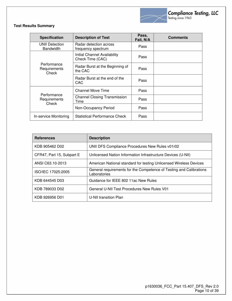
Test Results Summary
Specification Description of Test Pass,
Fail, N/A Comments
UNII Detection Bandwidth
Radar detection across frequency spectrum
Pass
Performance Requirements
Check
Initial Channel Availability Check Time (CAC)
Pass
Radar Burst at the Beginning of the CAC
Pass
Radar Burst at the end of the CAC
Pass
Performance Requirements
Check
Channel Move Time Pass
Channel Closing Transmission Time
Pass
Non-Occupancy Period Pass
In-service Monitoring Statistical Performance Check Pass
References Description
KDB 905462 D02 UNII DFS Compliance Procedures New Rules v01r02
CFR47, Part 15, Subpart E Unlicensed Nation Information Infrastructure Devices (U-NII)
ANSI C63.10-2013 American National standard for testing Unlicensed Wireless Devices
ISO/IEC 17025:2005 General requirements for the Competence of Testing and Calibrations Laboratories
KDB 644545 D03 Guidance for IEEE 802 11ac New Rules
KDB 789033 D02 General U-NII Test Procedures New Rules V01
KDB 926956 D01 U-NII transition Plan

p1630036_FCC_Part 15.407_DFS_Rev 2.0
Page 11 of 39
Requirement Operational Mode
Master Client Without Radar
Detection Client With Radar
Detection
Non-Occupancy Period Yes Not required Yes
DFS Detection Threshold Yes Not required Yes
Channel Availability Check Time Yes Not required Not required
U-NII Detection Bandwidth Yes Not required Yes
Requirement Operational Mode
Master Device or Client with Radar Detection
Client Without Radar Detection
DFS Detection Threshold Yes Not required
Channel Closing Transmission Time Yes Yes
Channel Move Time Yes Yes
U-NII Detection Bandwidth Yes Not required
Additional requirements for devices with multiple bandwidth modes
Master Device or Client with Radar Detection
Client Without Radar Detection
U-NII Detection Bandwidth and Statistical Performance Check
All BW modes must be tested Not required
Channel Move Time and Channel Closing Transmission Time
Test using widest BW mode available Test using the widest BW mode available for the link
All other tests Any single BW mode Not required
Note: Frequencies selected for statistical performance check (Section 7.8.4) should include several frequencies within the radar detection bandwidth and frequencies near the edge of the radar detection bandwidth. For 802.11 devices it is suggested to select frequencies in each of the bonded 20 MHz channels and the channel center frequency.

p1630036_FCC_Part 15.407_DFS_Rev 2.0
Page 12 of 39
Maximum Transmit Power Value
(See Notes 1, 2, and 3)
EIRP ≥ 200 milliwatt -64 dBm
EIRP < 200 milliwatt and power spectral density < 10 dBm/MHz
-62 dBm
EIRP < 200 milliwatt that do not meet the power spectral density requirement -64 dBm
Note 1: This is the level at the input of the receiver assuming a 0 dBi receive antenna. Note 2: Throughout these test procedures an additional 1 dB has been added to the amplitude of the test transmission waveforms to account for variations in measurement equipment. This will ensure that the test signal is at or above the detection threshold level to trigger a DFS response. Note3: EIRP is based on the highest antenna gain. For MIMO devices refer to KDB Publication 662911 D01.
Parameter Value
Non-occupancy period Minimum 30 minutes
Channel Availability Check Time 60 seconds
Channel Move Time 10 seconds See Note 1.
Channel Closing Transmission Time 200 milliseconds + an aggregate of 60 milliseconds over remaining 10 second period. See Notes 1 and 2.
U-NII Detection Bandwidth Minimum 100% of the U-NII 99% transmission power bandwidth. See Note 3.
Note 1: Channel Move Time and the Channel Closing Transmission Time should be performed with Radar Type 0. The measurement timing begins at the end of the Radar Type 0 burst. Note 2: The Channel Closing Transmission Time is comprised of 200 milliseconds starting at the beginning of the Channel Move Time plus any additional intermittent control signals required to facilitate a Channel move (an aggregate of 60 milliseconds) during the remainder of the 10 second period. The aggregate duration of control signals will not count quiet periods in between transmissions. Note 3: During the U-NII Detection Bandwidth detection test, radar type 0 should be used. For each frequency step the minimum percentage of detection is 90 percent. Measurements are performed with no data traffic.

p1630036_FCC_Part 15.407_DFS_Rev 2.0
Page 13 of 39
Radar Type Pulse Width
(μsec) PRI
(μsec) Number of
Pulses
Minimum Percentage of
Successful Detection
Minimum Number of
Trials
0 1 1428 18 See Note 1 See Note 1
1 1 Test A/Test B See 905462 D02 60% 30
2 1-5 150-230 23-29 60% 30
3 6-10 200-500 16-18 60% 30
4 11-20 200-500 12-16 60% 30
Aggregate (Radar Types 1-4) 80% 120
Note 1: Short Pulse Radar Type 0 should be used for the detection bandwidth test, channel move time, and channel closing time tests.

p1630036_FCC_Part 15.407_DFS_Rev 2.0
Page 14 of 39
Radar Type
Pulse Width (μsec)
Chirp Width (MHz)
PRI (μsec)
Number of Pulses per Burst
Number of Bursts
Minimum Percentage of
Successful Detection
Minimum Number of
Trials
5 50-100 5-20 1000-2000 1-3 8-20 80% 30
Note: The center frequency for each of the 30 trials of the Bin 5 radar is randomly selected within 80% of the Occupied Bandwidth. Each waveform is defined as follows:
1. The transmission period for the Long Pulse Radar test signal is 12 seconds.
2. There are a total of 8 to 20 Bursts in the 12 second period, with the number of Bursts being randomly chosen. This number is Burst Count.
3. Each Burst consists of 1 to 3 pulses, with the number of pulses being randomly chosen. Each Burst within the 12 second sequence may have a different number of pulses.
4. The pulse width is between 50 and 100 microseconds, with the pulse width being randomly chosen. Each pulse within a Burst will have the same pulse width. Pulses in different Bursts may have different pulse widths.
5. Each pulse has a linear frequency modulated chirp between 5 and 20MHz, with the chirp width being randomly chosen. Each pulse within a Burst will have the same chirp width. Pulses in different Bursts may have different chirp widths. The chirp is centered on the pulse. For example, with radar frequency of 5300MHz and a 20MHz chirped signal, the chirp starts at 5290MHz and ends at 5310MHz.
6. If more than one pulse is present in a Burst, the time between the pulses will be between 1000 and 2000 microseconds, with the time being randomly chosen. If three pulses are present in a Burst, the random time interval between the first and second pulses is chosen independently of the random time interval between the second and third pulses.
7. The 12 second transmission period is divided into even intervals. The number of intervals is equal to Burst Count. Each interval is of length (12,000,000 / Burst Count) microseconds. Each interval contains one Burst. The start time for the Burst, relative to the beginning of the interval, is between 1 and [(12,000,000 / Burst Count) – (Total Burst Length) + (One Random PRI Interval)] microseconds, with the start time being randomly chosen. The step interval for the start time is 1 microsecond. The start time for each Burst is chosen randomly.
A representative example of a Long Pulse Radar Type waveform:
1. The total test waveform length is 12 seconds.
2. Eight (8) Bursts are randomly generated for the Burst Count.
3. Burst 1 has 2 randomly generated pulses.
4. The pulse width (for both pulses) is randomly selected to be 75 microseconds.
5. The PRI is randomly selected to be at 1213 microseconds.
6. Bursts 2 through 8 are generated using steps 3 – 5.
7. Each Burst is contained in even intervals of 1,500,000 microseconds. The starting location for Pulse 1, Burst 1 is
randomly generated (1 to 1,500,000 minus the total Burst 1 length + 1 random PRI interval) at the 325,001
microsecond step. Bursts 2 through 8 randomly fall in successive 1,500,000 microsecond intervals (i.e. Burst 2
falls in the 1,500,001 – 3,000,000 microsecond range).

p1630036_FCC_Part 15.407_DFS_Rev 2.0
Page 15 of 39
Radar Type
Pulse Width (μsec)
PRI (μsec)
Pulses per Hop
Hopping Rate (kHz)
Hopping Sequence
Length (msec)
Minimum Percentage of Successful
Detection
Minimum Number of
Trials
6 1 333 9 0.333 300 70% 30
The first frequency in a hopping sequence is selected randomly from the group of 475 integer frequencies from 5250 – 5724MHz. Next, the frequency that was just chosen is removed from the group and a frequency is randomly selected from the remaining 474 frequencies in the group. This process continues until all 475 frequencies are chosen for the set. For selection of a random frequency, the frequencies remaining within the group are always treated as equally likely.

p1630036_FCC_Part 15.407_DFS_Rev 2.0
Page 16 of 39
Conducted Setup for Master with injection at the Master

p1630036_FCC_Part 15.407_DFS_Rev 2.0
Page 17 of 39
Conducted Setup for Client with injection at the Client

p1630036_FCC_Part 15.407_DFS_Rev 2.0
Page 18 of 39
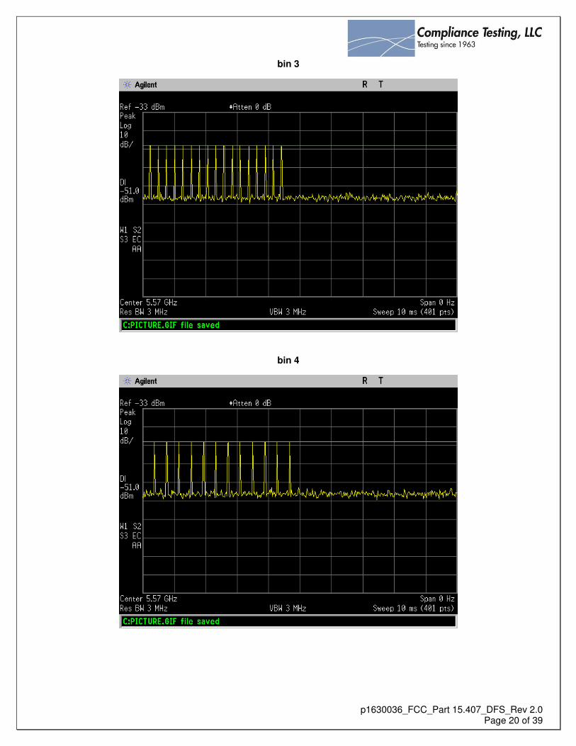
Radar Waveform Calibration
The equipment was setup per the diagram below. The amplitude of each wave form adjusted to compensate for the lowest antenna gain used with the EUT.
Waveform Calibration Test Setup Diagram
bin 0

p1630036_FCC_Part 15.407_DFS_Rev 2.0
Page 19 of 39
bin 1
bin 2
p1630036_FCC_Part 15.407_DFS_Rev 2.0
Page 20 of 39
bin 3
bin 4

p1630036_FCC_Part 15.407_DFS_Rev 2.0
Page 21 of 39
bin 5
bin 6

p1630036_FCC_Part 15.407_DFS_Rev 2.0
Page 22 of 39
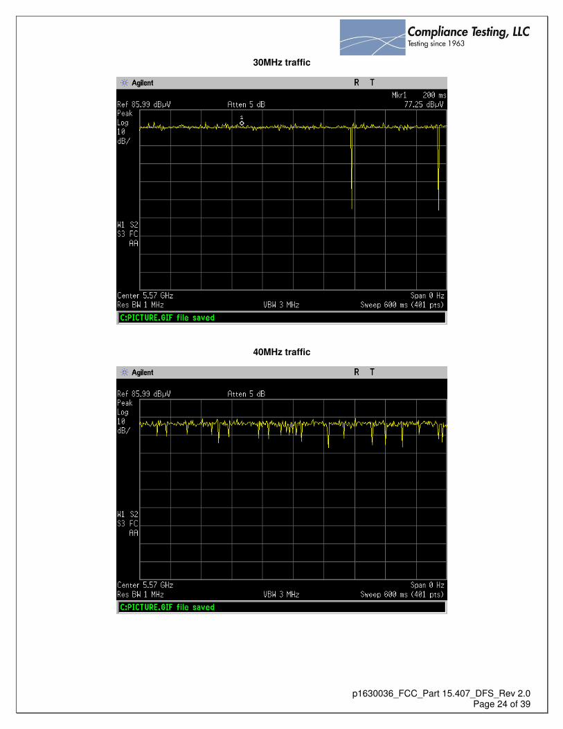
Channel Loading
Engineer: Paul Hay
Test Date:
Test Requirements
System testing will be performed with channel-loading using means appropriate to the data types that are used by the unlicensed device. The following requirements apply: a) The data file must be of a type that is typical for the device (i.e., MPEG-2, MPEG-4, WAV, MP3, MP4, AVI, etc.) and must generally be transmitting in a streaming mode. b) Software to ping the client is permitted to simulate data transfer but must have random ping intervals. c) Timing plots are required with calculations demonstrating a minimum channel loading of approximately 17% or greater. For example, channel loading can be estimated by setting the spectrum analyzer for zero span and approximate the Time On/ (Time On + Off Time). This can be done with any appropriate channel BW and modulation type.
Test Procedure The data file is streamed from the master to the client. The spectrum analyzer is set to 3MHz RBW and 3MHz VBW with a sweep time of 600ms. The plots below show the traffic for each bandwidth tested.

p1630036_FCC_Part 15.407_DFS_Rev 2.0
Page 23 of 39
10MHz traffic
20MHz traffic
p1630036_FCC_Part 15.407_DFS_Rev 2.0
Page 24 of 39
30MHz traffic
40MHz traffic

p1630036_FCC_Part 15.407_DFS_Rev 2.0
Page 25 of 39
U-NII Detection Bandwidth
Engineer: Poona Saber
Test Date: 8/15/16
Test Requirements The U-NII Detection Bandwidth must meet the U-NII Detection Bandwidth criterion as specified in 905462. Otherwise, the EUT does not comply with DFS requirements. In the case that the U-NII Detection Bandwidth is greater than or equal to the 99 percent power bandwidth for the measured FH and FL, the test can be truncated and the U-NII Detection Bandwidth can be reported as the measured FH and FL.
Test Procedure
The EUT was setup as a standalone device with no associated client and with no traffic. A single radar burst of types 0-4 was injected into the EUT at the center frequency of the channel and the response noted. A minimum of 10 trials was performed. The frequency of the radar signal was then decreased in 5MHz steps until the detection fell below the U-NII detection criterion. The frequency was then increased 5MHz and then decreased in 1MHz steps until the detection rate began to fall. This was noted as FL. This was repeated on the other side of the center of the carrier and the frequency noted as FH The U-NII Detection Bandwidth was calculated as follows:
U-NII Detection Bandwidth = FH – FL
Band Widths (MHz)
FH (MHz)
FL (MHz)
FH-FL (MHz)
99% BW (MHz)
Delta (MHz)
10 5575 5564 11 8.8 2.2
20 5580 5560 20 17.7 2.3
30 5586 5555 31 26.7 5.3
40 5590 5540 40 36.5 4.5
See Annex A for statistical Bandwidth test results

p1630036_FCC_Part 15.407_DFS_Rev 2.0
Page 26 of 39
Initial CACT
Engineer: Poona Saber
Test Date: 8/15/16
Initial Channel Availability Check Time criteria
Definition The Initial Channel Availability Check Time tests that the EUT does not emit beacon, control, or data signals on the test Channel until the power-up sequence has been completed and the U-NII device checks for Radar Waveforms for one minute on the test Channel. Test Procedure The monitoring spectrum analyzer was set to a zero span with a 3 MHz RBW and a 3 MHz VBW with a sweep time of 2.5 minutes. The EUT was powered on and instructed to operate on the appropriate U-NII Channel that incorporates DFS functions. At the same time the EUT was powered on the spectrum analyzer was triggered to sweep. Requirement The EUT should not transmit any beacon or data transmissions until at least 1 minute after the completion of the power-on cycle.
CACT

p1630036_FCC_Part 15.407_DFS_Rev 2.0
Page 27 of 39
Radar Burst at the Beginning of the Channel Availability Check Time
Definition The Radar Burst at the Beginning of the Channel Availability Check Time is to verify successful radar detection on the test channel during a period equal to the channel availability check time. A radar burst equal to the DFS detection threshold + 1dB is used. Test Procedure The monitoring spectrum analyzer was set to a zero span with a 3 MHz RBW and a 3 MHz VBW with a sweep time of 2.5 minutes. The EUT was powered on and instructed to operate on the appropriate U-NII Channel that incorporates DFS functions. At the same time the EUT was powered on the spectrum analyzer was triggered to sweep. A single Burst of one of the Short Pulse Radar Types 0-4 was commenced within a 6 second window starting at the beginning of the channel availability check time. An additional 1 dB was added to the radar test signal to ensure it was at or above the DFS Detection Threshold.
Requirement During the 2.5 minute measurement window the EUT will not transmit on that channel.
burst at beginning of CAC
p1630036_FCC_Part 15.407_DFS_Rev 2.0
Page 28 of 39
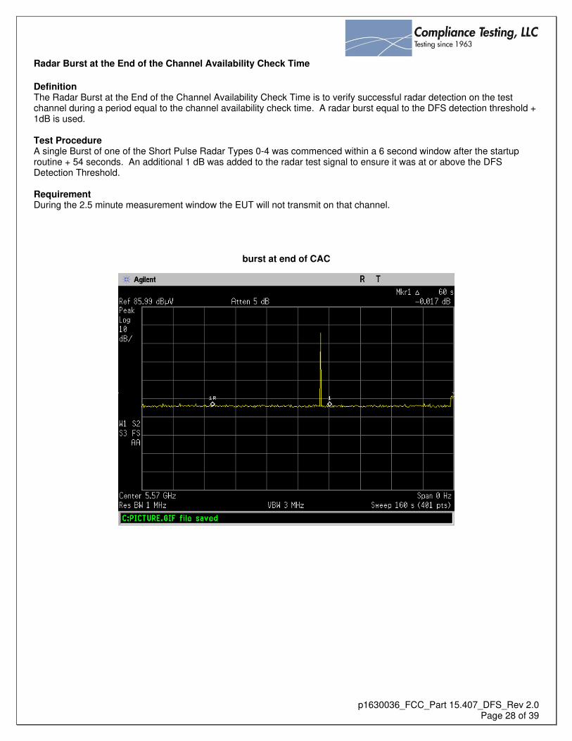
Radar Burst at the End of the Channel Availability Check Time
Definition The Radar Burst at the End of the Channel Availability Check Time is to verify successful radar detection on the test channel during a period equal to the channel availability check time. A radar burst equal to the DFS detection threshold + 1dB is used. Test Procedure A single Burst of one of the Short Pulse Radar Types 0-4 was commenced within a 6 second window after the startup routine + 54 seconds. An additional 1 dB was added to the radar test signal to ensure it was at or above the DFS Detection Threshold. Requirement During the 2.5 minute measurement window the EUT will not transmit on that channel.
burst at end of CAC

p1630036_FCC_Part 15.407_DFS_Rev 2.0
Page 29 of 39
In-Service Monitoring for Channel Move Time, Channel Closing Transmission Time and Non-Occupancy Period These tests define how the following DFS parameters are verified during In-Service Monitoring; - Channel Closing Transmission Time - Channel Move Time - Non-Occupancy Period The steps below define the procedure to determine the above mentioned parameters when a radar Burst with a level equal to the DFS Detection Threshold + 1dB is generated on the Operating Channel of the U-NII device (In- Service Monitoring).
a. One frequency will be chosen from the Operating Channels of the EUT within the 5250-5350MHz or 5470-5725MHz bands. For 802.11 devices, the test frequency must contain control signals. This can be verified by disabling channel loading and monitoring the spectrum analyzer. If no control signals are detected, another frequency must be selected within the emission bandwidth where control signals are detected.
b. In case the EUT is a U-NII device operating as a Client Device (with or without DFS), a U-NII device operating as a Master Device will be used to allow the EUT (Client device) to Associate with the Master Device. In case the EUT is a Master Device, a U-NII device operating as a Client Device will be used and it is assumed that the Client will Associate with the EUT (Master). In both cases for conducted tests, the Radar Waveform generator will be connected to the Master Device. Stream the channel loading test file from the Master Device to the Client Device on the test Channel for the entire period of the test.
c. At time T0 the Radar Waveform generator sends a Burst of pulses for one of the Radar Type 0. An additional 1 dB is added to the radar test signal to ensure it is at or above the DFS Detection Threshold, accounting for equipment variations/errors.
d. Observe the transmissions of the EUT at the end of the radar Burst on the Operating Channel for duration greater than 10 seconds. Measure and record the transmissions from the EUT during the observation time (Channel Move Time). Measure and record the Channel Move Time and Channel Closing Transmission Time if radar detection occurs.
e. When operating as a Master Device, monitor the EUT for more than 30 minutes following instant T2 to verify that the EUT does not resume any transmissions on this Channel. Perform this test once and record the measurement result.
f. In case the EUT is a U-NII device operating as a Client Device with In-Service Monitoring, perform steps a) to f).

p1630036_FCC_Part 15.407_DFS_Rev 2.0
Page 30 of 39
channel close
channel move

p1630036_FCC_Part 15.407_DFS_Rev 2.0
Page 31 of 39
30 min non-occupancy

p1630036_FCC_Part 15.407_DFS_Rev 2.0
Page 32 of 39
Statistical Performance Check
The steps below define the procedure to determine the minimum percentage of successful detection requirements when a radar burst with a level equal to the DFS Detection Threshold + 1dB is generated on the Operating Channel of the U-NII device (In- Service Monitoring).
a) One frequency will be chosen from the Operating Channels of the EUT within the 5250-5350MHz or 5470-5725MHz bands.
b) In case the EUT is a U-NII device operating as a Client Device (with or without Radar Detection), a U-NII device operating as a Master Device will be used to allow the EUT (Client device) to Associate with the Master Device. In case the EUT is a Master Device, a U-NII device operating as a Client Device will be used and it is assumed that the Client will associate with the EUT 905462 D02 UNII DFS Compliance Procedures New Rules v01r02 Page 37 (Master). In both cases for conducted tests, the Radar Waveform generator will be connected to the Master Device. Stream the channel loading test file from the Master Device to the Client Device on the test Channel for the entire period of the test.
c) At time T0 the Radar Waveform generator sends the individual waveform for each of the Radar Types 1- 6 on the Operating Channel. An additional 1 dB is added to the radar test signal to ensure it is at or above the DFS Detection Threshold, accounting for equipment variations/errors.
d) Observe the transmissions of the EUT at the end of the Burst on the Operating Channel for duration greater than 10 seconds for Radar Type 0 to ensure detection occurs.
e) Observe the transmissions of the EUT at the end of the Burst on the Operating Channel for duration greater than 22 seconds for Long Pulse Radar Type 5 to ensure detection occurs.
f) In case the EUT is a U-NII device operating as a Client Device with In-Service Monitoring, perform steps a) to f). Long Pulse Radar Test Three subsets of trials are performed with a minimum of ten trials per subset. The frequency is determined below:
a) The Channel center frequency
b) Tuned frequencies such that 90% of the Long Pulse Type 5 frequency modulation is within the low edge of the UUT Occupied Bandwidth and
c) Tuned frequencies such that 90% of the Long Pulse Type 5 frequency modulation is within the high edge of the UUT Occupied Bandwidth.
See Annex B for Statistical Performance Check results

p1630036_FCC_Part 15.407_DFS_Rev 2.0
Page 33 of 39
For subset case 1: the center frequency of the signal generator isfixed at
the center of the UUT Channel.
For subset case 2: 90% frequency overlap between the radar signal and
the UUT Occupied Bandwidth, the center frequency of the signal
generator will vary for each of the ten trials in subset case 2. The center
frequency of the signal generator for each trial is calculated by:
� + ( . ∗ �ℎ��� ����ℎ [�� ��])

p1630036_FCC_Part 15.407_DFS_Rev 2.0
Page 34 of 39
For subset case 3: 90% frequency overlap between the radar signal and the
UUT Occupied Bandwidth, the center frequency of the signal generator
will vary for each of the ten trials in subset case 3. The center frequency of
the signal generator for each trial is calculated by: ��−( . ∗�ℎ��� ����ℎ [�� ��])

p1630036_FCC_Part 15.407_DFS_Rev 2.0
Page 35 of 39
Short Pulse Radar Test Summary
Once the performance requirements check is complete, statistical data will be gathered to determine the ability of the device to detect the radar test waveforms. The device can utilize a test mode to demonstrate when detection occurs to prevent the need to reset the device between trials. The percentage of successful detection is calculated by: T a Wav D c iT a Wav T ia = Percentage of Successful Detection Radar Waveform N = PdN
In addition an aggregate minimum percentage of successful detection across all Short Pulse Radar Types 1-4 is required and is calculated as follows: Pd + Pd + Pd + Pd
10MHz Bandwidth
Radar Type Number of Trials Number of Successful
Detections Minimum Percentage of
Successful Detection
1 30 30 100%
2 30 30 100%
3 30 30 100%
4 30 30 100%
Aggregate (100% + 100% + 100% + 100% )/4 = 100%
20MHz Bandwidth
Radar Type Number of Trials Number of Successful
Detections Minimum Percentage of
Successful Detection
1 30 30 100%
2 30 30 100%
3 30 30 100%
4 30 30 100%
Aggregate (100% + 100% + 100% + 100% )/4 = 100%

p1630036_FCC_Part 15.407_DFS_Rev 2.0
Page 36 of 39
30MHz Bandwidth
Radar Type Number of Trials Number of Successful
Detections Minimum Percentage of
Successful Detection
1 30 30 100%
2 30 30 100%
3 30 28 93.3%
4 30 30 100%
Aggregate (100% + 100% + 93.3% + 100%)/4 = 98.3%
40MHz Bandwidth
Radar Type Number of Trials Number of Successful
Detections Minimum Percentage of
Successful Detection
1 30 30 100%
2 30 30 100%
3 30 28 93.3%
4 30 30 100%
Aggregate (100% + 100% + 93.3% + 100%)/4 = 98.3%
See Annex C for Bins 1-4 used for all Bandwidth tests

p1630036_FCC_Part 15.407_DFS_Rev 2.0
Page 37 of 39
Long Pulse Radar Test Statistical data will be gathered to determine the ability of the device to detect the Long Pulse Radar Type 5. The device can utilize a test mode to demonstrate when detection occurs to prevent the need to reset the device between trials. The percentage of successful detection is calculated by: T a Wav D c iT a Wav T ia x 100
10MHz Bandwidth
Radar Type Number of Trials Number of Successful
Detections Minimum Percentage of
Successful Detection
5 30 30 100%
20MHz Bandwidth
Radar Type Number of Trials Number of Successful
Detections Minimum Percentage of
Successful Detection
5 30 29 96.7%
30MHz Bandwidth
Radar Type Number of Trials Number of Successful
Detections Minimum Percentage of
Successful Detection
5 30 25 83.3%
40MHz Bandwidth
Radar Type Number of Trials Number of Successful
Detections Minimum Percentage of
Successful Detection
5 30 29 96.7%
See Annex D for Bin 5 used for all Bandwidth tests

p1630036_FCC_Part 15.407_DFS_Rev 2.0
Page 38 of 39
Frequency Hopping Radar Test Statistical data will be gathered to determine the ability of the device to detect the Frequency Hopping radar test signal. The probability of successful detection is calculated by: T a Wav D c iT a Wav T ia x 100
10MHz Bandwidth
Radar Type Number of Trials Number of Successful
Detections Minimum Percentage of
Successful Detection
6 30 30 100%
20MHz Bandwidth
Radar Type Number of Trials Number of Successful
Detections Minimum Percentage of
Successful Detection
6 30 30 100%
30MHz Bandwidth
Radar Type Number of Trials Number of Successful
Detections Minimum Percentage of
Successful Detection
6 30 30 100%
40MHz Bandwidth
Radar Type Number of Trials Number of Successful
Detections Minimum Percentage of
Successful Detection
6 30 30 100%

p1630036_FCC_Part 15.407_DFS_Rev 2.0
Page 39 of 39
Test Equipment Utilized
Description Manufacturer Model # CT Asset # Last Cal
Date Cal Due
Date
Spectrum Analyzer Keysight E4445A i00471 8/26/15 8/26/16
Signal Generator Hewlett Packard 83650A i00353 N/A N/A
PXI housing National Instruments PXI-1042
i00443
N/A N/A
Imbedded Controller National Instruments PXI-8106 N/A N/A
RF Up-converter National Instruments PXI-5610 N/A N/A
Arbitrary wave form generator
National Instruments PXI-5421 N/A N/A
Signal Generator Aeroflex PXI-3025 N/A N/A
RF Synthesizer Aeroflex PXI-3010 N/A N/A
Pre-amp Hewlett Packard 8449A i00028 N/A N/A
Combiner/Splitter Mini-Circuits ZX10R-14-S N/A N/A N/A
Mixer Mini-Circuits ZX05-83LH-S N/A N/A N/A
END OF TEST REPORT