fbo building prepared by - mcminnville, oregon · programming, conceptual cost estimating and...
TRANSCRIPT

New Facility Programming
Document for
McMinnville Municipal Airport FBO Building
Prepared by
January 2008

Table of Contents
Steele Associates Architects
Section 1 Executive Summary
Section 2 Existing Facility
Section 3 New Facility Program
Section 4 Facility Photos
Section 5 Conceptual Plans
Section 6 Conceptual Cost Analysis

Executive Summary
Steele Associates Architects
Introduction
This programming document represents the results of the combined work efforts of the Engineering
Services Manager, Rich Spofford, the Airport Manager, Judy Newman, FBO Operator Robbie
Sturm, and their selected architect team. The material contained herein reflect the result of the first
“big step” (Phase I) required in order to determine specific project requirements (building space
program, conceptual diagrams of the building(s) and site, consideration of site challenges) as well as
the “soft” and “hard” costs associated with the projects ultimate planning, design and construction
(Phase II).
Project Summary
The project is designed to replace the existing McMinnville Municipal Airport Building and FBO, as
the building in which they are currently located are grossly inefficient, outdated, and inadequate in
function and size to accommodate the growth of air traffic to the airport. The existing structure
which is cobbled together with former portable wooden military barrack buildings as well as newer
temporary buildings encompasses about 1,375 sq ft.
The desired mission of the new facility is to serve to alleviate the crowded, inefficient and potentially
unsafe conditions at the existing facility, and provide a modern, efficient, pleasant and expandable
facility to serve the City, its visitors and its constituents well into the future.
Project Scope
1. Interviews of city officials and key staff to determine space needs and design
expectations;
2. Site reconnaissance including review of the existing Airport Building, as well as the
former FAA Automated Flight Services Building;
3. Work product to include:
- Architectural space program for the project,
- Conceptual cost estimate to include both hard and soft costs,
- Integration of the building footprint(s), required parking, and other hardscape and
landscape features into the proposed site, as well as relating into the future proposed
site elements contained in the Airport Master Plan
4. A final document (this document) and presentation to include a colored plan on the
conceptual site plan with likely footprints/plans of the new Airport Building and FBO
within the site. An electronic .pdf version of this presentation (on CD) to be furnished to
the City.
5. A written report describing the architect’s initial (and, if requested, revised) work product
including who was interviewed, observations, explanations and other information that
will be helpful for the City. The architect shall provide 12 copies of the final report, also
in electronic format as described above.
It is important to note that early in the project, key airport staff identified the Madras General
Aviation Building as a desirable solution to the project. That project, which was completed in 2006,
was employed as a starting point, both in terms of program (space layout) as well as budget. It was
indicated to the architectural team that the cost of the project would be of concern, as there was
currently no money scheduled for the project. In response to this information, the team worked to
Executive Summary
Steele Associates Architects
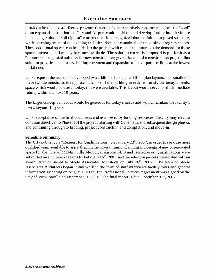
provide a flexible, cost-effective program that could be inexpensively constructed to form the “seed”
of an expandable solution the City and Airport could build on and develop further into the future
than a single phase “Full Option” construction. It is recognized that the initial proposed structure,
while an enlargement of the existing facilities, does not contain all of the desired program spaces.
These additional spaces can be added to the project with ease in the future, as the demand for those
spaces increase, and money becomes available. The solution currently proposed is put forth as a
“minimum” suggested solution for new construction; given the cost of a construction project, this
solution provides the best level of improvement and expansion to the airport facilities at the lowest
initial cost.
Upon request, the team also developed two additional conceptual floor plan layouts. The smaller of
these two demonstrates the approximate size of the building in order to satisfy the today’s needs,
space which would be useful today, if it were available. This layout would serve for the immediate
future, within the next 10 years.
The larger conceptual layout would be generous for today’s needs and would maintain the facility’s
needs beyond 10 years.
Upon acceptance of the final document, and as allowed by funding resources, the City may elect to
continue directly into Phase II of the project, starting with Schematic and subsequent design phases,
and continuing through to bidding, project construction and completion, and move-in.
Schedule Summary
The City published a “Request for Qualifications” on January 23rd
, 2007, in order to seek the most
qualified team available to assist them in the programming, planning and design of new or renovated
space for the City of McMinnville Municipal Airport FBO and related uses. Qualifications were
submitted by a number of teams by February 16th
, 2007, and the selection process culminated with an
award letter delivered to Steele Associates Architects on July 26th
, 2007. The team of Steele
Associates Architects began initial work in the form of staff interviews facility tours and general
information gathering on August 1, 2007. The Professional Services Agreement was signed by the
City of McMinnville on December 10, 2007. The final report is due December 31st, 2007.

Executive Summary
Steele Associates Architects
Team Introduction:
City of McMinnville
The consultant team would like to acknowledge the following individuals for their cooperation and
communication during the execution of this project effort:
City Staff
Rich Spofford, Engineering Services Manager
Mike Bisset, Community Development Director
Judy Newman, Airport Manager
Cirrus Aviation, LLC
Robbie Sturm, Owner/Manager
Consultant Team
The consultant team assigned to the McMinnville FBO feasibility project is composed of the
following firm and key individuals:
Steele Associates Architects, Bend, OR – Architect-Of-Record
Scott Steele, AIA, LEED – Principal-In-Charge
Stacey Stemach – Architect, LEED

Narrative
Steele Associates Architects
Owner City of McMinnville
Contact Person: Rich Spofford, Engineering Services Manager
Prepared by Steele Associates Architects LLC
Project Location McMinnville Municipal Airport, McMinnville, Oregon
Zoning The site is currently zoned as M-2. Airport related occupancies are
allowed in this zone.
Building Use The building will be constructed to replace the current FBO and
airport terminal building at the McMinnville Municipal Airport.
Project Description This project is split into (2) phases: Phase I which includes space
programming, conceptual cost estimating and master planning. Upon
acceptance of the Phase I programming and a approved version of the
master plan, Phase II will include design and construction services for
the new FBO Airport Building.
Facility Goals/ Objectives Overall, the site design and building architecture must be “timeless”
and welcoming, an iconic and identifiable gateway to McMinnville,
be designed and constructed with honesty (cost control), integrity, and
further stand with precedence as a civic icon of the city’s community.
Aside from designing a structure that creates pride in the community,
the building’s design must be durable, flexible, and expandable. In
addition, the project should incorporate sustainable design features to
encourage energy efficiency, reduction in waste and water usage, and
provide a healthy working environment.
Site Description The site under prime consideration for the new FBO Airport building
is located on the airport property, on a plot of land that currently
forms an “island” within a roadway loop currently serving as access
to the existing FBO, the former FAA Flight Services Building and the
airport apron. The site is approximately 168’-9” long (roughly east-
west), by 80’-4” wide (roughly north-south). This equates to
13,556.25 sq ft (0.31 acres). The site is flat and currently contains a
few street lights in good condition as well as fire hydrant
infrastructure, and storm drainage infrastructure that serves other
portions of the airport. The site is currently bounded on 4 sides by

Narrative
Steele Associates Architects
roadway.
In addition to the new FBO Airport building site, it is proposed to
include in this project an expansion of the existing aircraft parking
ramp in order to take advantage of space which can be freed by the
removal of the existing FBO structures. This will also provide an
increased efficiency in fueling procedures by removing structures and
obstructions around the existing fueling facility, thereby allowing
aircraft to approach and be directly serviced in close proximity.
Building Description The building is envisioned as a single story edifice which will serve
as a new municipal gateway for the City of McMinnville with
requisite parking and other site appurtenance, such as landscaping,
walkways and fencing. The dimensions and size of the new structure
will be determined as part of the initial conceptual design phase.
Systems Description This building is expected to incorporate the following mechanical,
electrical and plumbing systems:
Efficient heating and ventilation for freeze protection.
Water efficient plumbing to include sanitary sewer and rough
plumbing for break rooms, restrooms and general water use.
Electrical service to include site electrical and site lighting.
Building electrical to be basic services to building and special
equipment that is flexible to partition into each of the
departments. Energy efficient “Energy Star” rated appliances
will be specified where possible.
Fire protection system is expected to be a wet system that will
serve the entire building.
Additional information can be found in the New Facility
Program.
Sustainable Design As part of our standard services, Steele Associates Architects reviews
the potential for the building to use sustainable design strategies to
ensure energy efficiency, reduce water and waste consumption and
emphasize raising the standard of conventional building design and
construction. It is unknown at this time if this project will elect to
pursue LEED certification.
Existing Facility
Existing Facilities Information
There are several issues with the existing facilities that mandate the design of a new Airport
Terminal Building and FBO facility. The existing facility does not benefit the community of
McMinnville’s stature and fails to represent an image of strong economic development or
historical significance. There is little connection between the existing facilities and the growing
collection of significant aviation history at the Evergreen Aviation Museum, and the surrounding
environment of the City of McMinnville. Contrary to the purpose of the building, the facility
completely lacks “civic stature”. The environment is spare, worn, and haphazard. There are
several rampant inefficiencies throughout the facility, such as inadequate personnel and storage
space, minimal control over security, inefficient electronic capabilities, and lack of ADA
accessibility. Due to the unplanned and cobbled together nature of the existing facilities, the
users are constantly challenged with difficult weather events and ongoing maintenance issues. In
addition, safety, code, and security issues abound. These issues include narrow
openings/doorways, questionable structural soundness, inadequate space for flight planning and
weather services, flight instruction and testing space, inadequate and uncomfortable waiting
space for the existing air traffic and inadequate and uncomfortable facilities for waiting pilots.
The grossly inadequate facility also hampers the users’ ability to conduct their work in an
efficient and proud manner.
The staff of the McMinnville Airport have recognized that many of the deficiencies of the
current facility is due to the fact that the structures being used are simply what was available.
The existing facility is a study in structure recycling, and while it has served the purpose, it is
rapidly approaching the end of useful life. Further renovation or alteration of the current facility
will do little to solve many of the issues raised by the operators and visitors of the airport.
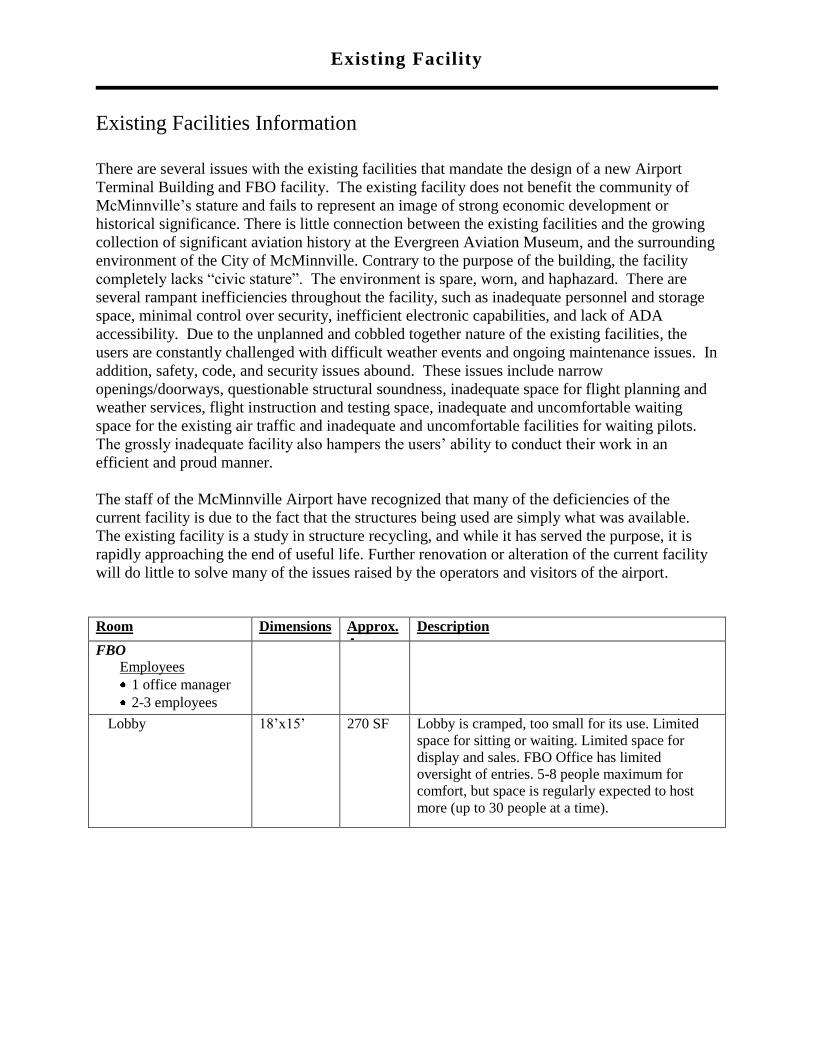
Room Dimensions Approx.
Area
Description
FBO
Employees
1 office manager
2-3 employees
Lobby 18’x15’ 270 SF Lobby is cramped, too small for its use. Limited
space for sitting or waiting. Limited space for
display and sales. FBO Office has limited
oversight of entries. 5-8 people maximum for
comfort, but space is regularly expected to host
more (up to 30 people at a time).

Existing Facility
Page 2 of 2
Teaching / multi-
purpose room
27’x15’ 405 SF This space is currently used for holding flight
instruction classes, pilot flight planning and
weather checking, flight simulation and overflow
from the lobby. This space is cramped and
inadequate for holding classes. There is no
separation or privacy for pilots working on flight
plans, or people using the flight simulator. 10
people maximum for instruction. This limits class
size and offering. Breakroom/kitchen 9’-4”x13-6” 126 SF Cramped space. Older out of date equipment and
poor access. Very limited cabinet and storage
space. FBO Office 11’-0”x12’-
0”
132 SF Cramped space. Constrained layout due to given
spaces as dictated by the building and uses. Little
view control over ramp and parking entries.
FBO Manager’s Office
and Testing
10’-0”x18’-
6”
185 SF Added on temporary building provides separate
office for FBO Manager. Also provides 3 spaces
for computer based testing and certification. FBO
Manager acts as test proctor and oversees the
testing candidates. Privacy is an issue. Testing
oversight is an issue. Poor visible connection
between office and rest of building.
Unisex Restroom Restroom is accessed only by the exterior. Not
accessible.
The total square footage of the existing building about 1,375 sq ft.
Also under consideration for this project is the airport facilities concerning aircraft approach,
access and parking at the FBO and fueling station.
The current arrangement allows for several light aircraft to be parked directly in front of the FBO
building. Larger aircraft are held away from the buildings and fueling to allow aircraft and
vehicular access. Because of the proximity of the fueling station to other structures and parked
aircraft, direct fueling of the aircraft from the fueling station is not possible, requiring the use of
fueling trucks for almost all aircraft.
The parking ramp area is tight and limits the maneuvering room of aircraft at the facility. The
airport currently receives a high volume of air traffic, including many large corporate jets.

New Facility Program
FACILITY SPACE PROGRAM
PREFACE
As described in the Executive Summary, Steele Associates Architects began the original
programming layout based on input from the airport staff identifying the Madras General
Aviation Building as a desirable layout to use as a starting point, both in terms of space layout
and budget.
Upon reviewing this starting point, it was determined that we should also document a proposed
layout which would address all of the spatial requirements as identified by the airport staff as
being needed in the present and the future. Thus, two additional schematic floor plans were
developed to demonstrate possible building layouts. The larger of the two plans would address
the needs of the airport for the foreseeable future, the smaller of the plans would address today’s
needs and the immediate future (less than 15 years).
The reality of today’s construction market, both nationally and locally, mandates that we do not
over-program our buildings. To check, we place an appropriate valuation on the construction of
each square foot of a building of this type (in this case, between $200 and $250), including
escalation of that number into the mid-point of the construction of the facility. Thus, it becomes a
simple exercise to conduct preliminary projections to ascertain the cost and therefore, the
constructability, of a building. Thus:
OPTION ‘A’ (Present needs)
Revised Program Square Footage: 3,230 SF
Projected Cost per Square Foot: $160 PSF (average)
Estimated Construction Cost: $516,800
OPTION ‘B’ (Future anticipated)
Revised Program Square Footage: 4,821 SF
Projected Cost per Square Foot: $160 PSF (average)
Estimated Construction Cost: $771,360
The estimated costs listed here are the hard building construction costs and do not include site
costs and soft costs such as financing, design fees, legal fees etc. These additional costs can run
20-25% more.
The existing facility is currently located at a line separating the existing parking ramp and the
public. Based on comments from airport staff suggesting congestion in airport parking and
maneuvering difficulties around the fueling facilities, it is recommended that the new FBO
facility be located further back from the existing parking ramp, closer to the FAA Automated
Flight Services Building. This will accomplish a number of goals with minimal overall costs: It
will allow additional aircraft parking to become available in an extended ramp area, it will free
up space around the existing fueling facility allowing more efficient fueling procedures and it
will allow the existing FBO facility to continue to function as it currently is during the
construction of the new facility.

Page 2 of 2
Another potential site includes a larger triangular site further from the airfield across the entry
drive from the existing FAA Automated Flight Services Building. While the site is entirely
suitable for use as a future FBO building, we feel its location is not ideal for its roll as a gateway
to the McMinnville Airport. Its visibility to the airfield is limited due to existing hangars and
other structures, it does not sit prominently on the access drive, clearly identifying its role.
If the new facility were to be constructed at the current location of the existing FBO, typical site
and infrastructure costs would be expected. Existing utilities would need to be evaluated for
continued use for the new facility, and no savings in site development costs would be realized
due to the fact the proposed building footprints exceed the existing building. Expense of
relocating the FBO and operating it at an alternate location would need to be included in the soft
costs. Close proximity to the fueling facility could cause some complications during
construction, for both construction activities and fueling procedures.
Locating the new FBO building at the end of Cirrus drive would require some additional site
work, paving and landscaping, however the additional cost would be directly serving goals
identified as current needs.
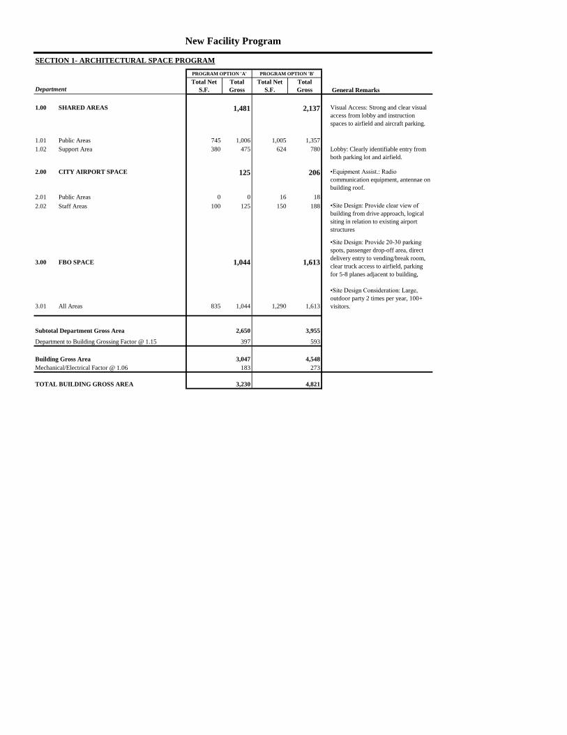
Department General Remarks
1.00 SHARED AREAS 1,481 2,137 Visual Access: Strong and clear visual
access from lobby and instruction
spaces to airfield and aircraft parking.
1.01 Public Areas 745 1,006 1,005 1,357
1.02 Support Area 380 475 624 780 Lobby: Clearly identifiable entry from
both parking lot and airfield.
2.00 CITY AIRPORT SPACE 125 206 •Equipment Assist.: Radio
communication equipment, antennae on
building roof.
2.01 Public Areas 0 0 16 18
2.02 Staff Areas 100 125 150 188
3.00 FBO SPACE 1,044 1,613
•Site Design: Provide 20-30 parking
spots, passenger drop-off area, direct
delivery entry to vending/break room,
clear truck access to airfield, parking
for 5-8 planes adjacent to building,
3.01 All Areas 835 1,044 1,290 1,613
•Site Design Consideration: Large,
outdoor party 2 times per year, 100+
visitors.
Subtotal Department Gross Area 2,650 3,955
Department to Building Grossing Factor @ 1.15 397 593
Building Gross Area 3,047 4,548
Mechanical/Electrical Factor @ 1.06 183 273
TOTAL BUILDING GROSS AREA 3,230 4,821
New Facility Program
SECTION 1- ARCHITECTURAL SPACE PROGRAM
•Site Design: Provide clear view of
building from drive approach, logical
siting in relation to existing airport
structures
PROGRAM OPTION 'A' PROGRAM OPTION 'B'
Total Net
S.F.
Total
Gross
Total Net
S.F.
Total
Gross

1.00 - SHARED SPACES - Airport and FBO
1.01 PUBLIC AREAS
ID Function Remarks
1 Weather Vestibule 1 0 0 120 120
2 Main Lobby (Shared) 1 30 585 585 585 585 Functional, warm, inviting, fireplace,
proper spatial layout
3 Vending/Breakroom 1 5 160 160 300 300 Coffee, Vending Machine,
Refridgerator, Freezer,
Storage/cabinets, dishwasher,
microwave, sink, counter space.
Provide direct access to exterior for
deliveries.
Department Net Area 745 1,005
Grossing Factor @ 1.35 261 352
Department Gross Area 1,006 1,357
1.00 - SHARED SPACES - Airport and FBO
1.02 SUPPORT AREAS
ID Function Remarks
1 Conference Room 1 10 150 150 200 200 Room large enough for about 10
people. Mixed-purpose room, can be
shared with instruction uses.
2 Janitor's Closet/Utility Room 1 30 30 64 64 Shared by whole facility. Provide mop
sink, mop and broom hooks, shelves
and some storage space. Larger room
shall also provide space for clothes
washer and dryer.
3 Public Toilets - Unisex 2 60 120 100 200 Accessible from main lobby
4 Public Shower- Unisex 1 50 50 80 80 Can be incorporated with Toilet Room
5 Telephone/Electrical 1 30 30 80 80 Ample room w/ air conditioning
Department Net Area 380 624
Grossing Factor @ 1.25 95 156
Department Gross Area 475 780
2.00 - AIRPORT USES
2.01 PUBLIC AREAS
ID Function Remarks
1 Information Kiosk 1 0 0 16 16 Incorporate awards display (plaques &
pictures)
Department Net Area 0 16
Grossing Factor @ 1.15 0 2
Department Gross Area 0 18
2.00 - AIRPORT USES
2.02 STAFF AREAS
ID Function Remarks
1 Airport Manager 1 1-2 100 100 150 150 Provide quiet location. Needs adequate
wall space for maps, desk and file
cabinets.
Department Net Area 100 150
Grossing Factor @ 1.25 25 38
Department Gross Area 125 188
PROGRAM OPTION 'A' PROGRAM OPTION 'B'
Unit Space
S.F.
Total Net
S.F.
Capacity
No. of
Rooms Capacity
Unit Space
S.F
Total Net
S.F.
PROGRAM OPTION 'B'
PROGRAM OPTION 'B'
Unit Space
S.F.
Total Net
S.F.
PROGRAM OPTION 'A'
Unit Space
S.F
Total Net
S.F.
No. of
Rooms Capacity
Unit Space
S.F
Unit Space
S.F
PROGRAM OPTION 'A'
No. of
Rooms
Total Net
S.F.
Total Net
S.F.
No. of
Rooms
Capacity
Unit Space
S.F.
Total Net
S.F.
Total Net
S.F.
PROGRAM OPTION 'A' PROGRAM OPTION 'B'
Unit Space
S.F.

3.00 FBO USES
3.01 ALL AREAS
ID Function Remarks
1 Reception Counter 1 2 100 100 160 160 Attached or In main Lobby. Provide
visual access over entire lobby, and out
to airfield/aircraft parking. Provide
display space in coutertop and or
display cases.
2 FBO Administration Office 1 2 100 100 160 160 Primary office space for FBO manager.
Typically for 1 person, but sized for 2
during bookkeeping, etc.
3 Test Proctor Room 1 4 160 160 220 220 Room for 4 (at the most) test taking
stations. Must have visual adjacency to
FBO Admin Office and/or Instructor's
room. 3 stations to start.
4 Simulator Room 1 3 85 85 100 100 Room for 2 simulators and instructor. 1
Single and 1 double, plus instructor
space.
5 Instructors Room 1 5 100 100 120 120 Room for up to 5 instructors. Provide 2
desks and 4 double drawer file cabinets
(8 drawers). Room serves as instructor's
office and file storage. Provide visual
access to parked aircraft.
6 Classroom 1 13 180 180 250 250 Provide flexible space, can be joined
with shared Conference Room. Provide
at least 3 tables and acoustic treatment
to allow multiple discussions at once.
10 students max, 3 instructors max.
7 Sleep Room 1 2 80 80 120 120 Sleep Room for pilots. With TV and up
to 2 recliners.
8 Pilot Toilet Room 1 0 0 100 100 Toilet Room with Shower. If included,
Public Shower to be deleted.
9 Weather and Flight Planning 1 30 30 60 60 Toilet Room with Shower. If included,
Public Shower to be deleted.
10 FBO Storage Room 1 50 50 100 100 Toilet Room with Shower. If included,
Public Shower to be deleted.
Department Net Area 835 1,290
Grossing Factor @ 1.25 209 323
Department Gross Area 1,044 1,613
PROGRAM OPTION 'A' PROGRAM OPTION 'B'
No. of
Rooms Capacity
Unit Space
S.F
Total Net
S.F.
Unit Space
S.F.
Total Net
S.F.

New Facility Program
SECTION 2 - SITEWORK/SITE IMPROVEMENTS
1. Parking:
Employees: 2-4 full time
Up to 5 part time instructors
2. Storage and Unloading:
Should provide easy access to vending/break area for deliveries
3. Access/ Drive Ramps: Concrete drive aprons with standard grade asphalt at parking
areas
4. Landscaping: Enhanced landscape to integrate with existing
5. Utilities: Basic Services (Water, Sewer, Elec. Gas, Cable, Phone, fiber)
6. Aircraft Ramp Parking: 5-8 light plans immediately adjacent to building. View
requirements from Lobby and Instruction Areas for observance of pre-flight
procedures.
7. Site lighting: Code compliant decorative fixtures with cut off guards for no light
trespass
8. Signage: Building mounted ornate signage
9. Flagpole: Flagpole located at front near pedestrian drop-off area.
10. Fencing: Security fencing for airport perimeter.
SECTION 3 - CONCRETE
1. Concrete shall be slab on grade at building first floor
2. Finish: Possible stained concrete or terrazzo finish at lobby
SECTION 4 - EXTERIOR
1. Material Palette: Anticipated mix of stone and/or CMU block for durability and
strength
2. Aesthetics: Timeless architecture that is pleasing, inviting and makes a statement.
SECTION 5 - STRUCTURAL SYSTEM
1. Concrete floor at first floor
2. Stud walls with stone or CMU veneer
3. Clear stained exposed wood post and beam construction
SECTION 6 - CARPENTRY
1. Casework: Reception areas, conference rooms, council chambers, break room, other
areas TBD
SECTION 7 - THERMAL AND MOISTURE PROTECTION
1. High Energy Performance

Page 2 of 4
a. Reduce operating costs
b. Design for comfort
2. Need good insulation values in the walls and roof
3. Membrane roof “white color” at areas of flat roof
SECION 8 - DOORS, WINDOWS AND GLASS
1. Windows/ Skylights
Must be energy efficient
View to airport very important
2. Doors:
Sizes 3’-0”x7’-0” HM or aluminum at exterior, solid core wood at interior
Doors with glass lights and/or sidelights desirable
3. Day lighting:
Incorporate where possible for added natural light
4. Views:
Visual connection to airport high priority
Views from Instruction to parked aircraft important
Views from Lobby to aircraft parking ramp important
SECTION 9 - FINISHES
1. Safe, Healthy work environment
a. Low VOC products important
b. Special ventilation needs to ensure worker health
2. Wall Finishes:
a. Offices/ Lobby/ Reception: Gypsum Wall Board (GWB) possibly with troweled
finish & accent color or upgraded to specialty panels
b. Training, Conference Rooms, GWB
c. Restrooms: tile wainscot, GWB
d. Storage areas: GWB
3. Floor finishes:
a. Offices, Training and Conference Rooms: Carpet
b. Lobby: Stained Concrete or tile
c. Vending/Snack areas, VCT or Linoleum
d. Restrooms: Linoleum or tile
4. Ceilings:
a. Offices, Training and Conference Rooms: ACT
b. Lobby: GWB articulated trim and soffits or wood slat system to create warmth
c. Restrooms: Moisture. Resistant GWB
5. Acoustics:
a. Separation between common and private areas and admin office space important
b. Restroom/ Conference and Training Room acoustic separation desired
SECTION 11 - EQUIPMENT
1. Computer and office equipment will be supplied by City/FBO.

Page 3 of 4
2. Projection Screen at Training Rooms
3. Wall area for Maps in Airport Manager’s Office and Training Rooms
4. Appliances (Energy Star) for common Break Room
SECTION 12 - FURNISHINGS 1. Offices: New desks and furniture, offices need room for file storage
2. Window treatments, vertical blinds
SECTION 13 - SPECIAL CONSTRUCTION 1. Room for Simulators (Single and double)
2. Room for computer testing.
SECTION 14 - CONVEYING SYSTEMS
1. Elevator Not anticipated
SECTION 15 - PLUMBING AND HVAC
HVAC Systems
Offices:
1. Design considerations: Zoned. Gas pack units to heat (12 hr vs. 24 hr zones).
2. Temperature: For thermal comfort Air Conditioning required.
Plumbing
1. Low flow plumbing fixtures for water reduction
2. Shower for pilots
3. Floor drains at restrooms, shower rooms
4. Hose bibs at exterior
SECTION 16 – FIRE PROTECTION SYSTEMS 1. Fire sprinkler system will be used throughout the facility
a. A wet system is anticipated
SECTION 17 - ELECTRICAL
1. Equipment
List to be determined by city and airport staff
2. Lighting
General illumination for office standards
Task lighting at desk tops
Fluorescent in offices, instruction/testing rooms with recessed can lights in
Lobby/Reception
Occupancy Sensor lighting system
3. Data and telephone throughout office area and at each department
4. Building low voltage and security systems
5. Battery backup for lighting and computer systems
6. Communication antennae

Page 4 of 4
SECTION 17 – LEED/ SUSTAINABLE STATEGIES
1. Maximize Day lighting
2. Solar Hot Water
3. Photovoltaic panels possible on roof
4. Building Flushing (draw in cool night air and exhaust building heat)
5. Heat transfer from heat generating departments
6. Native vegetation
7. Controlled stormwater run-off from site
8. Permeable hardscape parking?
9. Low flow plumbing fixtures?

Conceptual Cost Analysis
Steele Associates Architects
This cost analysis is based upon a conceptual program without drawings, and includes many
assumptions. Actual costs may vary greatly.
Option A (Present Needs Program) Department SF Cost/SF Cost Total
Shared Areas
Public Areas 1,006 $163 $ 163,820
Support Areas 475 $150 $ 71,250
1,481SF $ 235,070
City Airport Space
Staff Areas 125 $170 $ 21,250
125 $ 21,250
FBO Space
Staff Areas 1,044 $170 $ 177,480
1,044SF $ 177,480
Corridors/Common Space 397SF $140 $ 55,550
Mechanical/Electrical 183SF $150 $ 27,450
_________________________________________________________________________
Building Costs 3,230 sf $160/SF $ 516,800
_________________________________________________________________________
Site Development Costs 60,000sf 4.00/SF $ 240,000
(Includes estimated paving and
potential utility relocation)
___________________________________________________________________________
Subtotal $ 756,800
Contingency @ 10% $ 75,680
Owner’s Soft Costs @15% (A/E Fees @ 9%) $ 113,520
___________________________________________________________________________
Total $ 946,000

Conceptual Cost Analysis
Steele Associates Architects
Option B (Future Needs Program) Department SF Cost/SF Cost Total
Shared Areas
Public Areas 1,357 $163 $ 221,160
Support Areas 780 $150 $ 117,000
2,137SF $ 338,160
City Airport Space
Public Areas 18 $170 $ 3,060
Staff Areas 188 $170 $ 31,960
206SF $ 35,020
FBO Space
Staff Areas 1,613 $170 $ 274,210
1,613 SF $ 274,210
Corridors/Common Space 593SF $140 $ 83,020
Mechanical/Electrical 273SF $150 $ 40,950
_________________________________________________________________________
Building Costs 4,821 $160/SF $ 771,360
_________________________________________________________________________
Site Development Costs 60,000sf 4.00/SF $ 240,000
(Includes estimated paving and
potential utility relocation)
___________________________________________________________________________
Subtotal $ 1,011,360
Contingency @ 10% $ 101,136
Owner’s Soft Costs @15% (A/E fees @ 9%) $ 151,704
___________________________________________________________________________
Total $ 1,024,440