fault tree and cause consequence analysis for control...
TRANSCRIPT
General rights Copyright and moral rights for the publications made accessible in the public portal are retained by the authors and/or other copyright owners and it is a condition of accessing publications that users recognise and abide by the legal requirements associated with these rights.
• Users may download and print one copy of any publication from the public portal for the purpose of private study or research. • You may not further distribute the material or use it for any profit-making activity or commercial gain • You may freely distribute the URL identifying the publication in the public portal
If you believe that this document breaches copyright please contact us providing details, and we will remove access to the work immediately and investigate your claim.
Downloaded from orbit.dtu.dk on: Jun 01, 2018
Fault tree and cause consequence analysis for control software validation
Forskningscenter Risø, Roskilde
Publication date:1982
Document VersionPublisher's PDF, also known as Version of record
Link back to DTU Orbit
Citation (APA):Taylor, J. R. (1982). Fault tree and cause consequence analysis for control software validation. (Risø-M; No.2326).
RISØ-M-2326
FAULT TREE AND CAUSE CONSEQUENCE ANALYSIS
FOR CONTROL SOFTWARE VALIDATION
J.R. Taylor
Abstract. A theory underlying application of automatic fault
tree analysis to computer programs is described.
INIS Descriptors: COMPUTER CODES; FAULT TREE ANALYSIS; FAILURE
MODE ANALYSIS.
UDC 681.3.06:519.248
January \'..,6? Ri.;r Cat. i:' :\;>.\. Jnb^ratory, DK-4000 Roskilde, Denmark
ISBN 87-550-0819-4 ISSN :;<':: ?-C ' . "
Rice ve^.ro 193 2
TABLE OF CONTENTS
Page
INTRODUCTION 5
FAULT TREE ANALYSIS 6
FAULT TREE ANALYSIS FOR SOFTWARE 8
ASSIGNMENT STATEMENT 9
LOOPS AND INDUCTION 10
WHILE STATEMENT 11
FEATURES OF THIS APPROACH 12
TREATMENT OF FUNCTIONS AND SUBROUTINES 13
PROCEDURE CALL 14
WAIT AND SIGNAL STATEMENTS 14
SHARED VARIABLES IN CRITICAL SECTIONS 15
FORK AND JOIN 16
PREDICATE TRANSFORMER RULES FOR STRONGEST POST
CONDITIONS OF x = x^ 17
INTERRUPTS 18
REFERENCES 20


- 5 -
FAULT TREE AND CAUSE CONSEQUENCE ANALYSIS FOR CONTROL SOFTWARE
VALIDATION
Introduction
In many areas of computer application, safety depends on freedom
from software error. Examples a-e elevator control, control of
chemical plants, railway signalling and control, nuclear reactor
safety systems and aircraft landing systems. For systems such as
these it is important to be able either to guarantee freedom
from error, or to be able to reduce the probability of failure
in operations. For example a nuclear reactor shutdown system
should fail at a rate which is typically less than once per 10
program executions.
Path domain testing [1], [2], [3], [4], comes close to satisfy
ing the need for a guarantee of freedom from error. If along
each path through a program a single variable polynomial is com
puted of maximum order n, then n + 1 tests per path will reveal
all computation errors. A similar number of tests of domain
boundaries will detect most control errors, if conditional state
ment predicates involve only single variables. If several
variables are involved in path predicates or in path compu
tations then n tests will not necessarily reveal all errors,
since an actual path predicate or path computation may corre
spond coincidentally to the correct predicate or computation for
all test cases. This will happen if the hypersurfaces for thr.
actual and correct polynomials touch or cut each other at each
test point. The probability of this will generally be very low,
if more than just a i rf test points are chosen at random.
The remaining group of errors undetected by thorough path domain
testing are missing program paths corresponding to special input
data cases. To find these, path domain predicates may be com
pared with formal program specifications [5].

- 6 -
The main advantage of path domain testing, when compared with
proof of program correctness is avoidance of the need for a for
mal specification. It is known that provision of formal specifi
cations is extremely error prone [6]. Additionally, even infor
mal specifications are subject to error, accounting for some
50% of failures in operating software. Systematic testing
overcomes some of these problems, by allowing the programmer to
deal with program performance on a case by case basis.
One way of checking the correctness of test outputs in path
domain testing is to execute the program along with a model of
the plant to be controllr The model is checked to ensure that
its performance in respon.s to computer outputs is satisfactory.
This leads to the arrangement shown in fig. 1. Here the plant
model provides the specification of correct performance.
00HT40L. IUPVTS
T£ST
COMPUTES PCANT
not>ec ACTIO MS
%fi>F£Ty
M O M i TO*?
Fig. 1« Arrargement for software testing with a model.
Fault tree analysis
Automated fault tree analysis [7.8,9 J makes use of finite state
models of plant components which are very much like predicate
trans-'.Jr.M;r3 used in deriving path predicates. Each component is
described by means of a set of statements, termed mini-fault
trees, or trie form

- 7 -
"if x occurs at the input tc a component, and if the
state of the component is Y then x* will occur at the
output of the component, and the new component state
will be Y'"
In building up a fault tree a "top event" is chosen within a
component, generally some undesired event, such as an explosion
or crash. This event is matched to output events of mini fault
trees for the component, and any matching mini-fault trees are
added to the overall fault tree for the system. If there are
several matching mini-fault trees, they are connected into the
overall fault tree via an OR gate.
Having found an initial match, indicating a "first level" cause
of the top event, in an input, or internal state change event X
within the component, causes of this event are then sought. If
X is an internal state change event, mini fault trees with X as
a resulting event are sought for. If X is an input event, mini
fault trees providing a cause for X are sought in the components
connected to that in which X occurs.
This process is iterated, building up chains of events backwards
in time. The chains branch via an AND gate whenever both an
event X and a state Y are required for an event X* to occur. The
chains branch via an OR gate whenever there are two potential
ways in which an event X occurs (fig. 2). The process of build
ing up an event chain terminates when either a "spontaneous"
event is found (that is one for which no specific further cause
is defined), or a "normal" event or state is found, that is one
which will occur frequently during normal operation of a plant.
The process of building up the fault tree terminates when all
event chains have been terminated with "normal" or "spontaneous
events".
It is necessary to store the state of components as the fault
tre.3 + a biii.it up, since if two chains, 'anded* together, arrive
at the same component (due to a feedback or feed forward loop in
the bystem) tuen the two chains must be checked for compatibil
ity. They may, for example, require that the component fulfil

- S -
two mutually exclusive conditions at the same time. If such a
condition is detected, then the event chains are rejected.
This building of event chains can be carried out in the forward
direction, in which case the process is known as consequence
analysis I*?]. The two processes may be combined into one pro
cedure, cause consequence analysis, in which the causes and con
sequences of a single "critical event" are sought. Heuristic
rules have been devised for systematic selection of critical
events in plant safety analysis [ II ].
Fault tree analysis for software
The analogy between state transition functions for hardware com
ponents and predicate transformers can be utilised in building
up fault trees for combined hardware and software systems. In
building up the trees, some unwanted event is identified within
the hardware and event chains are traced which can cause this
event. When a "computer" component is reached, events at the
output registers of the computer will be found. The "causes" of
these are register manipulation statements within the software.
Chains of "events" within the software are ther. sought by tracing
changes in program variables from statement to statement using a
predicate transformer technique, until program inputs are found
which are necessary for the particular event chain. The chains
can then be extended once again to hardware, seeking the poten
tial causes of the program input events found.
The mini fault tree notation can be applied to individual pro
gram statements, allowing a uniform process of hardware/software
fault tree construction. For each statement a set of mini fault
trees is generated according to the schemes shown in fig. 3.
These are a modified form of weakest precondition predicate
transformers used elsewhere in proving program correctness [H].
Tho V-rnts" in Lho nrogram iiiini fault trees are statements of
the form

- 9 -
Assignment statement
at t-1, P(E(x))
1 i
x := E (x)
I at t P (x)
x is a free variable represent
ing the vector of program vari
able values at different points
in the program.
t is a free variable representing
a pair -"earliest and latest time'.'
IF statement
E is an »pression.
IF B(x) THEN il : SI ELSE 12 z S2
SI and S2 are any statements
including compound statements.
CI and 12 are labels.
at t - l f B(x) ft Q(x)
1
1 at t , PC = 11 & Q(x)
! SI
I at t , P(x)
i IF ~ -
1 1
it t , P(x)
at t - 1 , B(x) ft R(x)
1 1
at t , PC = 12 ft R(x)
1 S2
1 a t t , P(x)
1
PC i s program
counter
Fip. 3. Mini fault trees for basic program statements.

"at tine t, predicate P becomes true of the program
variables"
There are three nain differences in the process of building
fault trees fcr hardware and software. Firstly, instead of there
being a simple natch between events and mini fault trees, as for
hardware, the software mini fault trees may match any predicate.
Secondly, the mini fault trees, when matched, must be niodified
by substituting the output predicate into the mini fault tree,
both at the input and output position. Thirdly, it is generally
necessary to simplify the predicates representing input and out
put events in the mini-fault trees. If this simplification re
sults in the predicate FALSE the event chain is abandoned.
Note that the form of fault '.ree for IF and WHILE statements
provides an OR branch for each direction of branching through
the statement. This ensures that all paths through a program
will be treated as different branches of the fault tree. This
has the advantage of ensuring greater understandability, and of
keeping individual predicates relatively simple. It has the dis
advantage of producing very large trees in many cases. For this
reason it h as been found advisable to insist on quite severe
structuring rules for programs to be used with this technique. -
"Separate (possibly parallel) programs should be provided for
each separate control or safety function within a computer sys
tem". This ruin er sures at least that the program paths followed
are relevant to trit anaJysts safety problem. An alternative
formulation of the str ucturing criterion can be applied system
atically. - It" th-:;re ar-3 two program outputs X and Y for which
the values are functions of sets of inputs I(X) and I(Y), then
if r (X) n r(Y; is empty, programs producing outputs X and Y
shoalJ be disjoint.
Loops and induction
With loop.- ir. a program, the size of the fault fees produced
may in-v •. rv '<Ai~ar.. or nay even grow indefinitely. For practical
pur, >scft, tao ru:. .:> r ,1 times the fault tree iterates round a

- 11 -
WILE statement
SI; WEILE B(x) DO S ; S3
SI
I at t-1, B(x) c P(x)
1
¥ at t-1 B(x> ft P(x)
~ ~ z i — ]
WHILE
I at tf P(x)
1— S3
SI
I at t-1, B(x) ft Q(x)
WHILE
I at t-1, B(x) ft Q(x)
tt | at t, Q(x) |

- Ik -
program loop must be limitec'.
Induction can be applied to the fault tree to show that no poss
ible program inputs lead to a dangerous event, in the following
way.
1. It is shown that no dangerous output is produced from
any input causing zero iterations round a loop.
2. It is shown that no dangerous outputs are produced from
any input causing one iteration round a loop.
3. It is shown that if no dangerous output has been pro
duced with n iterations around a loop, then no dangerous
output will be produced with n + 1 iterations.
This type of proof is aided by the graphic presentation of the
fault tree. The fault tree branch corresponding to the n + 1
iteration is generally similar in form or is a simple systematic
modification of the form of the branch corresponding to the n
iteration. If the forms can, by logical manipulation, be made
identical apart from the numerical constant n, then the induc
tion proof is completed.
Features of this approach
The main advantage of the approach outline here is that soft
ware testing is integrated into plant functional analysis and
failure analysis. The overall performance of plant and control
system can be investigated.
The problem of finding an unequivocal decision about which pro
gram outputs are "correct", which limits the usefulness of path
domain testing, are solved with this approach by referring to
the 'correct' or 'safe' performance of the plant model.
Problems or specification errors are to a large extent avoided
witn this approach. l>> formal specification of pre gram require-

- 13 -
ments need be made, and the "testing" is independent of the pro
gram specification. The plant component models used are drawn
from a library of standard models which are tested over a long
series of analyses. The models are derived by means of a stan
dardised procedure from physical equations for the components
[4]. in other words the test is very thorough and is independent
of the programming process.
Parallel processing is accounted for by the fault tree method in
a natural way.
The major problems with the fault tree approach to software
validation are the need for inductive proofs for programs with
loops, (these must be provided by the analyst), and the very
large size of fault trees formed. It is doubtful whether any
practical program could be validated as a whole. Rather, it
seems necessary to break down programs hierarchically, into sub
routines or modules.
Given that a proof of freedom from program error is carried
through using a fault tree approach, one might ask whether any
errors can remain in the program. Such weak points must arise
due to some common error in both the programming and plant mod
elling process. Three obvious sources are errors in the physical
description of the plant (plant flow sheet), errors in the plant
construction so that i does not accord with plant design, and
common misconceptions, shared by the programmer and the plant
model builder, about the way the plant works.
Treatment of functions and subroutines
Given the need for a hierarchical decomposition of the analysis
task, a question arises, 'how?'. One approach is to analyse
functions and subroutines separately, and to incorporate these
direcr..Lj into ;no program descriptions.
One way oi. doo-ng this is to evaluate the function which a sub
routine computes and to make use of the functional description

- 14 -
Procedure
| a
1
L f .
CALL
a t t
cal l
Q ( P ( x ) )
1 P (x)
1 Q (x) J
Note: It is necessary to
evaluate the function
calculated by P. See fig. 4
WAIT and SIGNAL statements
at t' Q(x)
at t Q(x)
at t S-"ON - I
V WAIT S
I
f < t
J Note: other semantics
for WAIT are possible
in which processing pro
ceeds if S is ON.
at t S-OFF
lat t, R(x)l 1
STGNAL S -J
| at t, R W
Note: No sharing of
variables is assumed
here - each program has
its own variables.
at t S-ON

- 15 -
Shared variables in critical sections
SI ; CRITICAL SECTION I WITH V DO S ; S3
\ r • 11
\ at f , Q(x) ] I at t V+FREE1 ' • J < a—i—c:
r at t, Q(x)
1*' ,< t J
1 at t V+OCCUPIED T\
SI
_ l _ a t t , Q(x)
—izz
I a t t , Q ( x ) )
1 S
^
a t t , V IS FREE
1
| a t t , V-»-OCCUPIED-E|
1 [ a t t R(x?
a t t , R (x)|
1 S3
S2 a t t v i s OCCUPIED-a
1 1 '
1 a t t V-+FREE
n~n

- 16 -
FORK and JOIN
S i FORK SI ; S2 JOIN ; S3
S
I
at f Rl(x) & R2(x)
at tl, Rl(x)
SI
f = MIN(t1|t2)
1 [at t2, R2(x)
S2
SI
at t , R(x)
S2
1 at t , R(x)

- 17 -
of the subroutine in building up the fault tree. A mini fault
tree for procedure calls without side effects is shown in fig.
3. The function calculated by a procedure can be found by conse
quence analysis/symbolic execution, applying the rules shown in
fig. 4. These work by finding the value of the program variable
vector after execution of a program statement, as a function of
the program var'able vector prior to execution of the statement.
Rules for finding these functions for individual statements are
then applied iteratively.
Predicate transformer rules for strongest post conditions of
x = = X o
x = F (xQ)
1 x := B(x)
l
x = E(F(xQ))
(x = F(x o)
IF B(X) THEN S= ELSE S2
X = IF B(F(XQ)) & SPC(Sl,F(xQ)) ELSE SPC (S2>F (xQ) )
X = F(xo)l
T WHILE B(x) DO S
I
X = IF B F(xo) THEN F (xQ)
ELSEIF B F(xQ) & B (SPC (K,F (XQ) ) ) THEN SPC(S,F(x ))
ELSEIF B F(x.) & B(SPC(S,F(XQ))) & B (SPC(S,SPC(S,F (x ) ) ) )
THEN SPC(S,SPC(S,F(X ) ))
ELSEIF

Interrupts
Three kinds of interrupts can be distinguished
- SiGNALS in which one process waits for an interrupt
from another before restarting
- EXCEPTIONS in which a program halts for some error re
covery action in case some exceptional con
dition is met
- ATTENTIONS in which a running program is halted by another
process, and is either STOPped, MODIFIEd, or
SUSPENDed awaiting a further RESUME command.
The first of these can be treated in the same way as WAIT and
SIGNAL described earlier.
EXCEPTIONS can be treated readily in mini-fault trees by attach
ing an additional predicate to each tree as follows.
P(E(x))
~ T — x := E(x)
EXEP(x) & P(E(x)) v EXEP(x) I
x := E(x) unless EXCEP(x)
(P(x) i
For STOP type interrupts the modification is as follows
a t
L,
t-
U
4.
\ S
1
P(x)
= *
at t-1 P(x) p.
INTERRUPT RErSflNS
( a t t Q ( x ) |
- 19 -
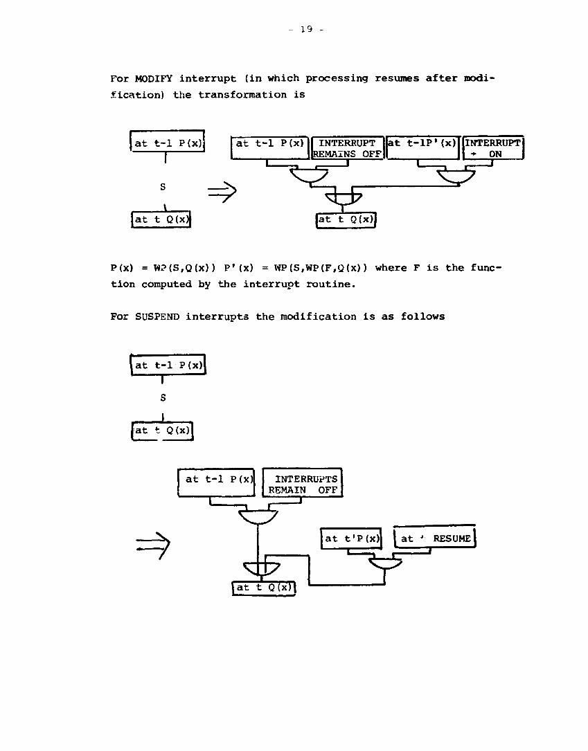
For MODIFY interrupt (in which processing resumes after modi
fication) the transformation is
at t -1 P(x)
1 o
j a t t - 1 P(x)
1 INTERRUPT
REMAINS OFF 1 . , 1
S }
» | a t t Q(x)|
y I
V> |at t Q(x)j
at t - l P ' ( x ) INTERRUPT •* ON
1 . . »
^ y
P(x) = W?(S,Q(x)) P'(x) = WP(S,WP(F,Q(x)) where F is the func
tion computed by the interrupt routine.
For SUSPEND interrupts the modification is as follows
(at t-1 P(x)|
[at t Q(x)'
at t-1 P(x)
—c= } — I
INTERRUPTS REMAIN OFF
Z3
*
at t'P(x)
\at t Q(x)(
I at *• RESUME1 . I '
y

- 20 -
References
1. J.C. Kuang, An Approach tc Program Testing, ACM Comcuting
Surveys, Vol. 7, No. J, September 1975.
2. L.J. White and E.T. Cohen, A Domain Strategy for Computer
Program Testing, IEEE Trans. Software Eng., Vol. SE6.
No. 3, May 1960.
3. W.E. Howden, Methodology -~^r the Generation cf Program Test
Data, IEEE Trans. Comp., Vol. C-24, May 197S.
4. J.R. Taylor and S. Bologna, Validation of Safety Related
Software, IAEA Specialist Meeting on Computerised Con
trol and Safety Systems in Nuclear Power Plants, Pitts
burgh, 1977.
5. S. Bologr.a et al., Deriving Test Data from Specifications,
Report RT/ING(78)3, CNEN, Italy, 1978.
Goode.ioug and S.L. Gerhardt. Towards a Theory of Test
Data Selection, IEEE Trans, on Software Engineering,
Vol. SE-1, No. 2, June 1975.
Taylor, Sequential Effects in Failure Mode Analysis.
In Reliability and Fauxt Tree Analysis, Ed. Barlow,
Fussel and Sinj»apurwal la, SIAM, 1975.
8. E. Hoiic and J.R. Taylor, Experience with Algorithms for
Automatic Failure Analysis, in Nuclear Systems Reli-
abiiity, J.B. ruosel and G.R. Burdidi, SIAM, 1977.
3. J.R. Taylor, */. Algorithm for Fault Tree Construction,
to he published in IEEE Trans. Reliability.
10. D.S. iJieif.cn, 1:^ Cause-^nsequence Method as a Basis for
'juantitativ A.-cider.t Analysis, Report Risø-M-1374.
kisc .\'a:. i <-r, a i Laboratory, 1971.
11. J.R. Taylor, A Background to Risk Analysis, Vol. 1 to 4,
list ;.Hfi.,r»ai Laboratory, 1979.
6. J.B.
7. J.R.
Risø National Laboratory 21 - Risø-M-[ 2326
(O
ro CM
•
i
Ti t le and author(s)
F a u l t Tree and Cause Consequence Ana ly s i s
f o r Con t ro l Software V a l i d a t i o n
J . R . Tay lor
pages + tables + i l lus t ra t ions
Date January 1982
Department or group
E l e c t r o n i c s
Group's own registrat ion number(s)
R- l -82
Abstract
A t h e o r y u n d e r l y i n g a p p l i c a t i o n of au tomat ic
f a u l t t r e e a n a l y s i s to computer programs i s
d e s c r i b e d .
Copies to
Available on request from Risø Library, Risø National I,A.si^^j (7:-^ Bibliotek), Forsøgsanlæg Risø), LX-4H00 Roskilde, Dinjn irk TtLi?i,hono: 101) 17 i: 12, ext. 2262. Telex: 43116