fault location in the outer sheath of power cablesopen access journal journal of power technologies...
TRANSCRIPT
Open Access Journal
Journal of Power Technologies 94 (4) (2014) 250–258journal homepage:papers.itc.pw.edu.pl
Fault location in the outer sheath of power cables
Qian Wanga, Chao Tang∗,b, Gaolin Wua, George Chenc
aState Grid Chongqing Electric Power Co. Chongqing Research InstituteChongqing 401123, China
bCollege of Engineering and Technology, Southwest UniversityChongqing 400715, China
cSchool of Electronics and Computer Science, University of SouthamptonSouthampton SO17 1BJ, United Kingdom
Abstract
With the development of power systems in recent years, the total amount of power cables in operation hasincreased greatly, and there are growing reports of cable failure. Cable failures may be due to various intrinsicor extrinsic factors and can lead to massive economic loss. With regard to high-voltage cables, such as 110 kVpower cables, there are very few accurate reports on the actual fault observed. This article first analyses thepossible causes of power cable outer sheath failure. It then introduces the bridge and step voltage methods,which are traditionally used for cable fault locating, and describes a new method for accurate fault locatingin 110 kV cables, which uses the bridge method to pre-locate the fault and then the step voltage method toaccurately determine the precise fault locating. Field testing confirms the applicability of the new method foraccurate fault locating in 110 kV power cables. The results shown in this article may provide a good referencefor the development of future research in related fields.
Keywords: Power cable outer sheath, Fault locating, Bridge method, Step voltage method
1. Introduction
Power cables are the major component of elec-tric power grids, serving as a means of power trans-mission and distribution, and include outgoing linesfrom power plants, cross-river and cross-ocean un-derwater transmission lines, city underground gridsystems and internal power supplies for industrialand mining enterprises. In recent years, city powergrids have grown, and cables are used increasinglywidely, playing an extremely important role in dailycity life. As an example, the length of power ca-bles in one city in China reached 725 km by the end
∗Corresponding authorEmail address: [email protected] (Chao Tang∗,)
of 2007, accounting for more than 40% of the entire10 kV distribution network lines in that city [1]. Fur-thermore, in 2002, the length of cables carrying morethan 10 kV in the power grid of Guangzhou Cityreached 3885 km [2]. By April 2010, the numberof 110 kV and 220 kV power cables under the man-agement of the cable section of the power distribu-tion department of Shenzhen Power Supply Bureaureached 190 km, and the total length was 412 km [3].Any damage to cables may result in blackouts oreven more serious consequences. A typical exampleto illustrate this point is the power transmission fail-ure that resulted from an oil leakage and subsequentpressure loss in the 500 kV oil-filled cable at ShajiaoPlant C, which was caused by white ants [4]. Thisled to significant direct losses, as well as further in-
Journal of Power Technologies 94 (4) (2014) 250–258
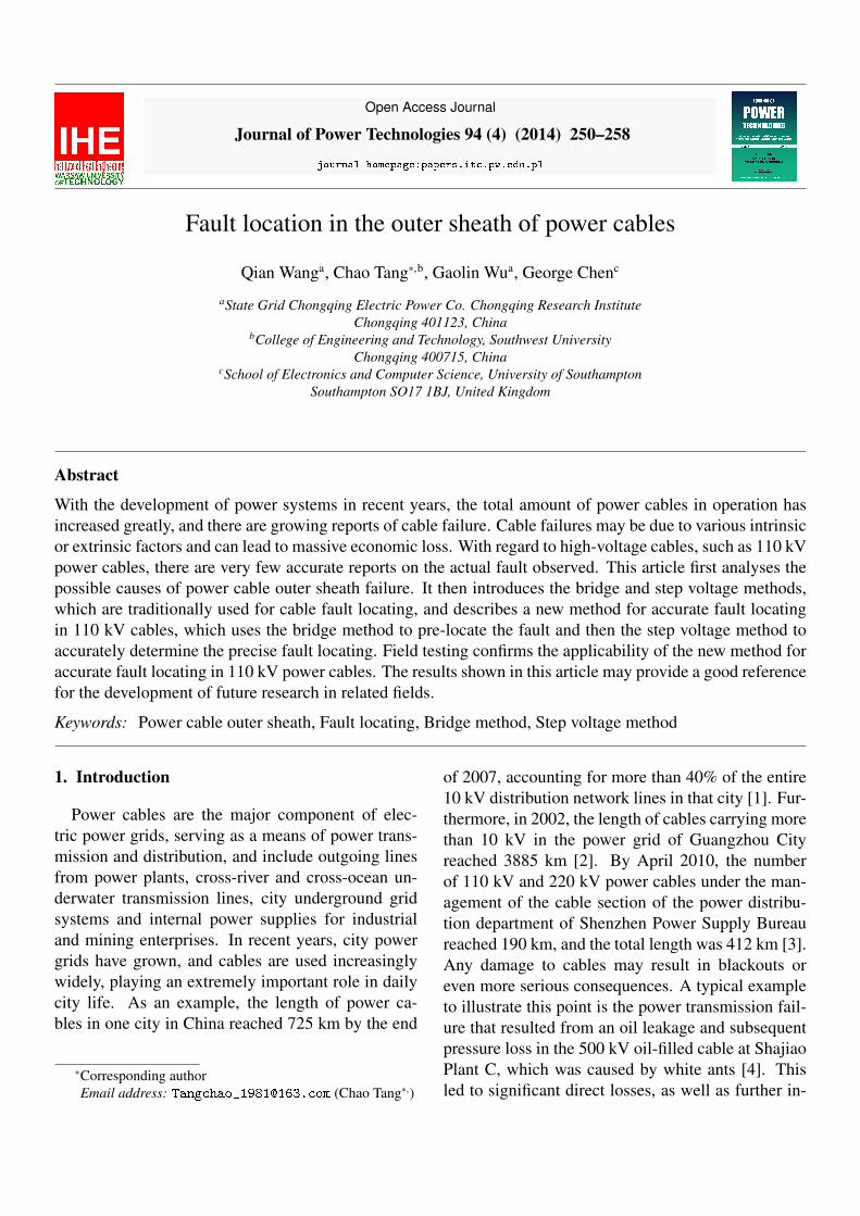
Figure 1: Structure of the single-core cable
calculable losses due to the subsequent blackout. InJuly 2012, a blackout at a pipe plant in ChangzhouCity, Jiangsu Province, resulted in a sudden shut-down of the processing and production line, and thefurnace charge of that production batch was a totalloss. Furthermore, components in the manufacturingplant cracked due to the sudden cooling, and the pre-liminary estimated economic loss amounted to morethan 100,000 Yuan.
At present, the step voltage and bridge meth-ods are commonly used to locate cable outer sheathfaults [5–10]. The bridge method is based on thebridge balance principle, and it is applied by mea-suring the degree of deviation in resistance. The lo-cation of the fault can then be calculated based onthe relationship between the resistance and the cablelength. The step voltage method relies on measur-ing the degree of potential deviation between differ-ent points, with the location of the fault being de-termined according to the deflection and sway of thepointer.
In this article, the bridge method is first usedto broadly pre-locate the fault in a 110 kV cable(Shuhui Transmission Line), and then the step volt-age method is used to find the precise location ofthe fault. Through actual measurement, it has beenconfirmed that the pre-locating voltage method andthe accurate fixed point step voltage method are bothapplicable to status evaluation and fault locating in110 kV cable outer sheaths. The study described inthis article can be used as a reference for future re-search.
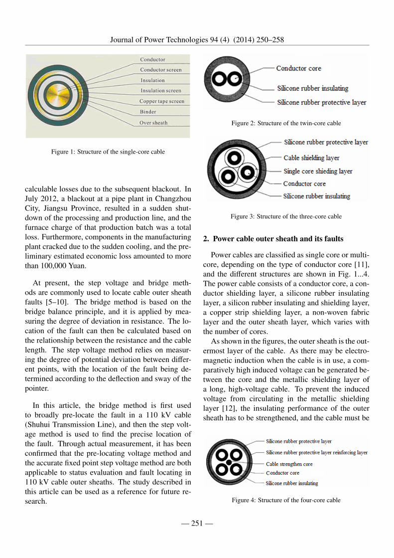
Figure 2: Structure of the twin-core cable
Figure 3: Structure of the three-core cable
2. Power cable outer sheath and its faults
Power cables are classified as single core or multi-core, depending on the type of conductor core [11],and the different structures are shown in Fig. 1...4.The power cable consists of a conductor core, a con-ductor shielding layer, a silicone rubber insulatinglayer, a silicon rubber insulating and shielding layer,a copper strip shielding layer, a non-woven fabriclayer and the outer sheath layer, which varies withthe number of cores.
As shown in the figures, the outer sheath is the out-ermost layer of the cable. As there may be electro-magnetic induction when the cable is in use, a com-paratively high induced voltage can be generated be-tween the core and the metallic shielding layer ofa long, high-voltage cable. To prevent the inducedvoltage from circulating in the metallic shieldinglayer [12], the insulating performance of the outersheath has to be strengthened, and the cable must be
Figure 4: Structure of the four-core cable
— 251 —
Journal of Power Technologies 94 (4) (2014) 250–258
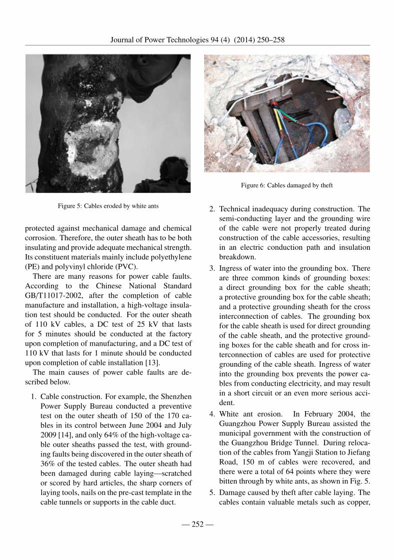
Figure 5: Cables eroded by white ants
protected against mechanical damage and chemicalcorrosion. Therefore, the outer sheath has to be bothinsulating and provide adequate mechanical strength.Its constituent materials mainly include polyethylene(PE) and polyvinyl chloride (PVC).
There are many reasons for power cable faults.According to the Chinese National StandardGB/T11017-2002, after the completion of cablemanufacture and installation, a high-voltage insula-tion test should be conducted. For the outer sheathof 110 kV cables, a DC test of 25 kV that lastsfor 5 minutes should be conducted at the factoryupon completion of manufacturing, and a DC test of110 kV that lasts for 1 minute should be conductedupon completion of cable installation [13].
The main causes of power cable faults are de-scribed below.
1. Cable construction. For example, the ShenzhenPower Supply Bureau conducted a preventivetest on the outer sheath of 150 of the 170 ca-bles in its control between June 2004 and July2009 [14], and only 64% of the high-voltage ca-ble outer sheaths passed the test, with ground-ing faults being discovered in the outer sheath of36% of the tested cables. The outer sheath hadbeen damaged during cable laying—scratchedor scored by hard articles, the sharp corners oflaying tools, nails on the pre-cast template in thecable tunnels or supports in the cable duct.
Figure 6: Cables damaged by theft
2. Technical inadequacy during construction. Thesemi-conducting layer and the grounding wireof the cable were not properly treated duringconstruction of the cable accessories, resultingin an electric conduction path and insulationbreakdown.
3. Ingress of water into the grounding box. Thereare three common kinds of grounding boxes:a direct grounding box for the cable sheath;a protective grounding box for the cable sheath;and a protective grounding sheath for the crossinterconnection of cables. The grounding boxfor the cable sheath is used for direct groundingof the cable sheath, and the protective ground-ing boxes for the cable sheath and for cross in-terconnection of cables are used for protectivegrounding of the cable sheath. Ingress of waterinto the grounding box prevents the power ca-bles from conducting electricity, and may resultin a short circuit or an even more serious acci-dent.
4. White ant erosion. In February 2004, theGuangzhou Power Supply Bureau assisted themunicipal government with the construction ofthe Guangzhou Bridge Tunnel. During reloca-tion of the cables from Yangji Station to JiefangRoad, 150 m of cables were recovered, andthere were a total of 64 points where they werebitten through by white ants, as shown in Fig. 5.
5. Damage caused by theft after cable laying. Thecables contain valuable metals such as copper,
— 252 —

Journal of Power Technologies 94 (4) (2014) 250–258
Figure 7: Detection principle of the bridge method connectiondiagram
and theft and attempted theft may cause damageto the cables (Fig. 6).
3. Fault detection methods for the outer sheath
Fault detection in the outer sheaths of power ca-bles generally relies on both "rough" and “accurate”locating methods. The “rough" location methods areused to locate the fault point in the cable, and arealso called the pre-locating methods for outer sheathfaults. The most common "rough" location methodis the bridge method, although for major cable insu-lation faults, the echo reflection method [15] may beapplied for pre-location. Accurate location mostlyrelies upon the step voltage method, although thevoice frequency method, the DC surge method andthe comprehensive method can also be used.
ri
rz=
Ri
Rz=
X2L − X
(1)
The detection principle of the bridge method—also called the Murray loop bridge—is shown inFig. 7 and Fig. 8. Phase A and Phase B are con-nected, the cable resistance is equivalent to ri, rz, Ri
and Rz in the bridge, and the resistance to ground ofthe fault point is equivalent to Rp. When the bridgebalance is achieved, Formula (1) can be used to de-termine the location of the fault point. However, theinsulating resistance of the fault point may vary withhumidity and temperature, as well as with the dam-age to, and the materials of, the outer sheath. In addi-tion, this method can be affected by various externalfactors [12], which is why it can only be used for"rough" location.
Figure 8: Detection principle of the bridge method
The principle of the step voltage method is shownin Fig. 9. It is applied by using a step voltage re-flecting machine to send out voltage signals. As theouter sheath at the point of the fault is damaged, thecable will directly connect with the ground. The gal-vanometer on the step voltage receiver measures thepotential of the circuit, and the pointer will point tothe middle position when the galvanometer is justabove the fault point, whereas when the galvanome-ter is located to the left of the fault, the pointer willdeflect rightwards, and when the galvanometer is tothe right of the fault, the pointer will deflect left-
Figure 9: Principle of the step voltage method
— 253 —

Journal of Power Technologies 94 (4) (2014) 250–258
Figure 10: Schematic diagram of the 110 kV extra-high-voltagepower cable line in Zigong (Shuhui Line)
wards. In theory, the larger the angle of deflectionis, the further the distance is from the fault. Thismethod requires no reading or calculation, and it isvery simple to use—and the result is more accurate.
The audio frequency locating method is based ona similar principle to the step voltage method, but isless intuitive. The comprehensive locating methodis used in some complicated circumstances, and themeasurements required are also quite complicated.
4. Actual measurement for outer sheath fault lo-cating
To study the accurate location of power cable outersheath faults in a better way, a location test was con-ducted on the outer sheath fault of a 110 kV cross-linking power cable (Shuhui Line). As requiredby Zigong Power Supply Co., Ltd. of the StateGrid Sichuan Electric Power Company, Bartsu In-strument Supply (Shanghai), Ltd. carried out a de-energized test for fault locating in the outer sheathof a 110 kV power cable (Shuhui Line), and accu-rately located the fault on the outer sheath betweenthe direct grounding box of China Mobile and theprotective grounding box of Huidong Substation.
4.1. Insulation resistance test on the outer sheath4.1.1. Test conditions
1. Rated voltage of the cable: 64/110 kV (Fig. 10).2. Cable model: YJLW02-64/110 kV 1×400 mm2.3. Cable manufacturer: Jiangsu Baosheng Prys-
mian Co., Ltd.4. Number of cable accessories: two groups of ca-
ble terminals, respectively located at Huidong
Figure 11: Shuhui Line cable termination, the 122 equipmentinterval of Huidong Substation
Substation and #31 steel pipe pole along theShuhui Line (both JB protective groundingboxes); one group of straight joints, located atChina Mobile (the JD direct grounding box wasfixed on the wall of the cable duct at the gate ofChina Mobile).
5. Installation of the cable accessories: ChanglanElectric Technology Co., Ltd (Changsha CableAccessories Co., Ltd.).
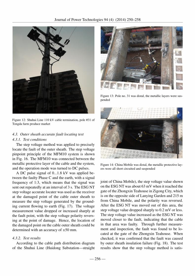
6. Overall length of the cable: 1,33 km, dividedinto two sections: the first section was 683 mlong (from Huidong Substation to China Mo-bile); the second section was 650 m long (fromChina Mobile to the #31 steel pipe pole ofShuhui Line). They are shown in Fig. 11 andFig. 12.
4.1.2. Test resultsThe test results of the outer sheath insulation resis-
tance, according to the 110 kV Cable (Shuhui LineAC Voltage Withstand Test Report) of 21 June 2013,are given in Table 1. The testing organization was theAnzhao Debugging Branch of Luzhou Special Trans-former Co., Ltd.
According to the Power Safety Specification, elec-tricity testing and ground sealing were carried out onHuidong Substation and #122 and #31 poles of theShuhui Line at 8:30 am on 30 November 2013. The
— 254 —
Journal of Power Technologies 94 (4) (2014) 250–258
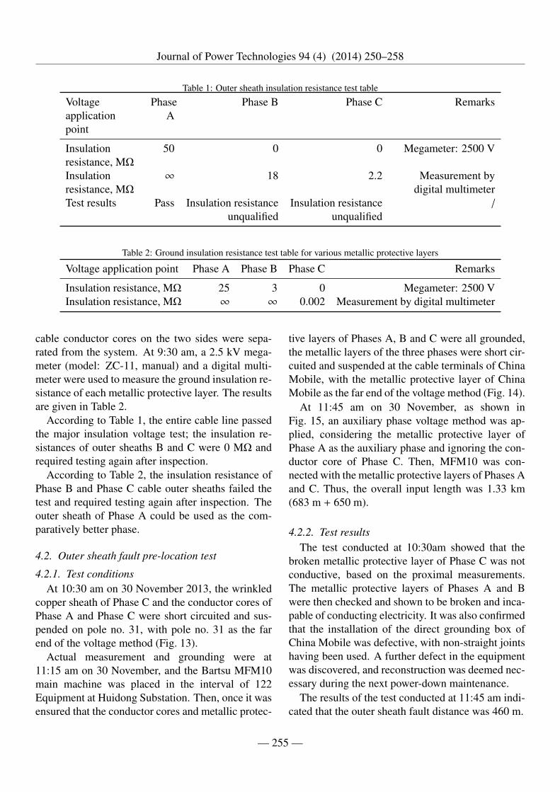
Table 1: Outer sheath insulation resistance test table
Voltageapplicationpoint
PhaseA
Phase B Phase C Remarks
Insulationresistance, MΩ
50 0 0 Megameter: 2500 V
Insulationresistance, MΩ
∞ 18 2.2 Measurement bydigital multimeter
Test results Pass Insulation resistanceunqualified
Insulation resistanceunqualified
/
Table 2: Ground insulation resistance test table for various metallic protective layers
Voltage application point Phase A Phase B Phase C Remarks
Insulation resistance, MΩ 25 3 0 Megameter: 2500 VInsulation resistance, MΩ ∞ ∞ 0.002 Measurement by digital multimeter
cable conductor cores on the two sides were sepa-rated from the system. At 9:30 am, a 2.5 kV mega-meter (model: ZC-11, manual) and a digital multi-meter were used to measure the ground insulation re-sistance of each metallic protective layer. The resultsare given in Table 2.
According to Table 1, the entire cable line passedthe major insulation voltage test; the insulation re-sistances of outer sheaths B and C were 0 MΩ andrequired testing again after inspection.
According to Table 2, the insulation resistance ofPhase B and Phase C cable outer sheaths failed thetest and required testing again after inspection. Theouter sheath of Phase A could be used as the com-paratively better phase.
4.2. Outer sheath fault pre-location test
4.2.1. Test conditionsAt 10:30 am on 30 November 2013, the wrinkled
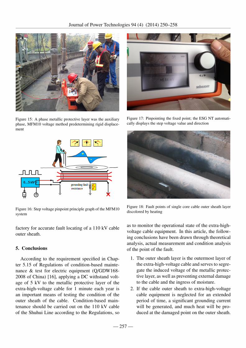
copper sheath of Phase C and the conductor cores ofPhase A and Phase C were short circuited and sus-pended on pole no. 31, with pole no. 31 as the farend of the voltage method (Fig. 13).
Actual measurement and grounding were at11:15 am on 30 November, and the Bartsu MFM10main machine was placed in the interval of 122Equipment at Huidong Substation. Then, once it wasensured that the conductor cores and metallic protec-
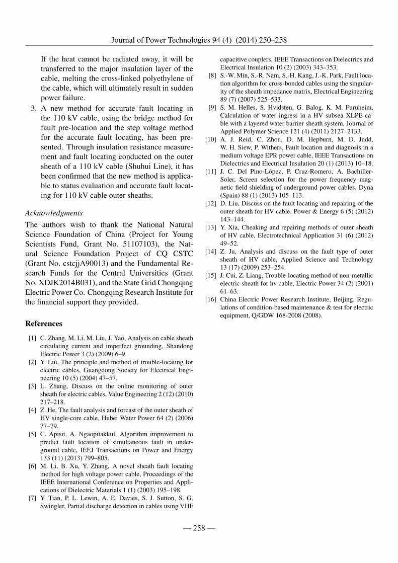
tive layers of Phases A, B and C were all grounded,the metallic layers of the three phases were short cir-cuited and suspended at the cable terminals of ChinaMobile, with the metallic protective layer of ChinaMobile as the far end of the voltage method (Fig. 14).
At 11:45 am on 30 November, as shown inFig. 15, an auxiliary phase voltage method was ap-plied, considering the metallic protective layer ofPhase A as the auxiliary phase and ignoring the con-ductor core of Phase C. Then, MFM10 was con-nected with the metallic protective layers of Phases Aand C. Thus, the overall input length was 1.33 km(683 m + 650 m).
4.2.2. Test resultsThe test conducted at 10:30am showed that the
broken metallic protective layer of Phase C was notconductive, based on the proximal measurements.The metallic protective layers of Phases A and Bwere then checked and shown to be broken and inca-pable of conducting electricity. It was also confirmedthat the installation of the direct grounding box ofChina Mobile was defective, with non-straight jointshaving been used. A further defect in the equipmentwas discovered, and reconstruction was deemed nec-essary during the next power-down maintenance.
The results of the test conducted at 11:45 am indi-cated that the outer sheath fault distance was 460 m.
— 255 —
Journal of Power Technologies 94 (4) (2014) 250–258
Figure 12: Shuhui Line 110 kV cable termination, pole #31 ofTongda farm produce market
4.3. Outer sheath accurate fault locating test4.3.1. Test conditions
The step voltage method was applied to preciselylocate the fault of the outer sheath. The step voltagepinpoint principle of the MFM10 system is shownin Fig. 16. The MFM10 was connected between themetallic protective layer of the cable and the system,and the operation mode was turned to DC pulses.
A DC pulse signal of 0...1.8 kV was applied be-tween the faulty Phase C and the earth, with a signalfrequency of 1:3, which means that the signal wassent out repeatedly at an interval of 3 s. The ESG NTstep voltage accurate locater was used as the receiverat the damaged point of the cable outer sheath tomeasure the step voltage generated by the ground-ing current flowing to earth (Fig. 17). The voltagemeasurement value dropped or increased sharply atthe fault point, with the step voltage polarity revers-ing at the point of damage. Hence, the location ofthe damaged point on the cable outer sheath could bedetermined with an accuracy of ±50 mm.
4.3.2. Test resultsAccording to the cable path distribution diagram
of the Shuhui Line (Huidong Substation—straight
Figure 13: Pole no. 31 was distal, the metallic layers were sus-pended
Figure 14: China Mobile was distal, the metallic protective lay-ers were all short circuited and suspended
joint of China Mobile), the step voltage value shownon the ESG NT was about 63 mV when it reached thegate of the Zhongxin Teahouse in Zigong City, whichis on the opposite side of Lanying Garden and 215 mfrom China Mobile, and the polarity was reversed.After the ESG NT was moved out of this area, thestep voltage value dropped sharply to 0.2 mV or less.The step voltage value increased as the ESG NT wasmoved closer to the fault, indicating that the cablein that area was faulty. Through further measure-ment and inspection, the fault was found to be lo-cated at the gate of the Zhongxin Teahouse. Whenchecked, it was confirmed that the fault was causedby outer sheath insulation failure (Fig. 18). The testresults show that the step voltage method is satis-
— 256 —
Journal of Power Technologies 94 (4) (2014) 250–258
Figure 15: A phase metallic protective layer was the auxiliaryphase, MFM10 voltage method predetermining rigid displace-ment
Figure 16: Step voltage pinpoint principle graph of the MFM10system
factory for accurate fault locating of a 110 kV cableouter sheath.
5. Conclusions
According to the requirement specified in Chap-ter 5.15 of Regulations of condition-based mainte-nance & test for electric equipment (Q/GDW168-2008 of China) [16], applying a DC withstand volt-age of 5 kV to the metallic protective layer of theextra-high-voltage cable for 1 minute each year isan important means of testing the condition of theouter sheath of the cable. Condition-based main-tenance should be carried out on the 110 kV cableof the Shuhui Line according to the Regulations, so
Figure 17: Pinpointing the fixed point; the ESG NT automati-cally displays the step voltage value and direction
Figure 18: Fault points of single core cable outer sheath layerdiscolored by heating
as to monitor the operational state of the extra-high-voltage cable equipment. In this article, the follow-ing conclusions have been drawn through theoreticalanalysis, actual measurement and condition analysisof the point of the fault.
1. The outer sheath layer is the outermost layer ofthe extra-high-voltage cable and serves to segre-gate the induced voltage of the metallic protec-tive layer, as well as preventing external damageto the cable and the ingress of moisture.
2. If the cable outer sheath to extra-high-voltagecable equipment is neglected for an extendedperiod of time, a significant grounding currentwill be generated, and much heat will be pro-duced at the damaged point on the outer sheath.
— 257 —
Journal of Power Technologies 94 (4) (2014) 250–258
If the heat cannot be radiated away, it will betransferred to the major insulation layer of thecable, melting the cross-linked polyethylene ofthe cable, which will ultimately result in suddenpower failure.
3. A new method for accurate fault locating inthe 110 kV cable, using the bridge method forfault pre-location and the step voltage methodfor the accurate fault locating, has been pre-sented. Through insulation resistance measure-ment and fault locating conducted on the outersheath of a 110 kV cable (Shuhui Line), it hasbeen confirmed that the new method is applica-ble to status evaluation and accurate fault locat-ing for 110 kV cable outer sheaths.
AcknowledgmentsThe authors wish to thank the National NaturalScience Foundation of China (Project for YoungScientists Fund, Grant No. 51107103), the Nat-ural Science Foundation Project of CQ CSTC(Grant No. cstcjjA90013) and the Fundamental Re-search Funds for the Central Universities (GrantNo. XDJK2014B031), and the State Grid ChongqingElectric Power Co. Chongqing Research Institute forthe financial support they provided.
References
[1] C. Zhang, M. Li, M. Liu, J. Yao, Analysis on cable sheathcirculating current and imperfect grounding, ShandongElectric Power 3 (2) (2009) 6–9.
[2] Y. Liu, The principle and method of trouble-locating forelectric cables, Guangdong Society for Electrical Engi-neering 10 (5) (2004) 47–57.
[3] L. Zhang, Discuss on the online monitoring of outersheath for electric cables, Value Engineering 2 (12) (2010)217–218.
[4] Z. He, The fault analysis and forcast of the outer sheath ofHV single-core cable, Hubei Water Power 64 (2) (2006)77–79.
[5] C. Apisit, A. Ngaopitakkul, Algorithm improvement topredict fault location of simultaneous fault in under-ground cable, IEEJ Transactions on Power and Energy133 (11) (2013) 799–805.
[6] M. Li, B. Xu, Y. Zhang, A novel sheath fault locatingmethod for high voltage power cable, Proceedings of theIEEE International Conference on Properties and Appli-cations of Dielectric Materials 1 (1) (2003) 195–198.
[7] Y. Tian, P. L. Lewin, A. E. Davies, S. J. Sutton, S. G.Swingler, Partial discharge detection in cables using VHF
capacitive couplers, IEEE Transactions on Dielectrics andElectrical Insulation 10 (2) (2003) 343–353.
[8] S.-W. Min, S.-R. Nam, S.-H. Kang, J.-K. Park, Fault loca-tion algorithm for cross-bonded cables using the singular-ity of the sheath impedance matrix, Electrical Engineering89 (7) (2007) 525–533.
[9] S. M. Helles, S. Hvidsten, G. Balog, K. M. Furuheim,Calculation of water ingress in a HV subsea XLPE ca-ble with a layered water barrier sheath system, Journal ofApplied Polymer Science 121 (4) (2011) 2127–2133.
[10] A. J. Reid, C. Zhou, D. M. Hepburn, M. D. Judd,W. H. Siew, P. Withers, Fault location and diagnosis in amedium voltage EPR power cable, IEEE Transactions onDielectrics and Electrical Insulation 20 (1) (2013) 10–18.
[11] J. C. Del Pino-López, P. Cruz-Romero, A. Bachiller-Soler, Screen selection for the power frequency mag-netic field shielding of underground power cables, Dyna(Spain) 88 (1) (2013) 105–113.
[12] D. Liu, Discuss on the fault locating and repairing of theouter sheath for HV cable, Power & Energy 6 (5) (2012)143–144.
[13] Y. Xia, Cheaking and repairing methods of outer sheathof HV cable, Electrotechnical Application 31 (6) (2012)49–52.
[14] Z. Ju, Analysis and discuss on the fault type of outersheath of HV cable, Applied Science and Technology13 (17) (2009) 253–254.
[15] J. Cui, Z. Liang, Trouble-locating method of non-metallicelectric sheath for hv cable, Electric Power 34 (2) (2001)61–63.
[16] China Electric Power Research Institute, Beijing, Regu-lations of condition-based maintenance & test for electricequipment, Q/GDW 168-2008 (2008).
— 258 —