fatigue response of udimet 720 following minimum...
TRANSCRIPT
Fatigue response of Udimet 720 following minimumdamage wire electrical discharge machiningAntar, Mohammad; Soo, Sein; Aspinwall, David; Sage, C.; Cuttell, M.; Perez, R.; Winn, A.J.
DOI:10.1016/j.matdes.2012.06.003
License:None: All rights reserved
Citation for published version (Harvard):Antar, MT, Soo, SL, Aspinwall, DK, Sage, C, Cuttell, M, Perez, R & Winn, AJ 2012, 'Fatigue response of Udimet720 following minimum damage wire electrical discharge machining' Materials & Design, vol 42, pp. 295-300.DOI: 10.1016/j.matdes.2012.06.003
Link to publication on Research at Birmingham portal
General rightsUnless a licence is specified above, all rights (including copyright and moral rights) in this document are retained by the authors and/or thecopyright holders. The express permission of the copyright holder must be obtained for any use of this material other than for purposespermitted by law.
•Users may freely distribute the URL that is used to identify this publication.•Users may download and/or print one copy of the publication from the University of Birmingham research portal for the purpose of privatestudy or non-commercial research.•User may use extracts from the document in line with the concept of ‘fair dealing’ under the Copyright, Designs and Patents Act 1988 (?)•Users may not further distribute the material nor use it for the purposes of commercial gain.
Where a licence is displayed above, please note the terms and conditions of the licence govern your use of this document.
When citing, please reference the published version.
Take down policyWhile the University of Birmingham exercises care and attention in making items available there are rare occasions when an item has beenuploaded in error or has been deemed to be commercially or otherwise sensitive.
If you believe that this is the case for this document, please contact [email protected] providing details and we will remove access tothe work immediately and investigate.
Download date: 10. Jul. 2018
(This is a sample cover image for this issue. The actual cover is not yet available at this time.)
This article appeared in a journal published by Elsevier. The attachedcopy is furnished to the author for internal non-commercial researchand education use, including for instruction at the authors institution
and sharing with colleagues.
Other uses, including reproduction and distribution, or selling orlicensing copies, or posting to personal, institutional or third party
websites are prohibited.
In most cases authors are permitted to post their version of thearticle (e.g. in Word or Tex form) to their personal website orinstitutional repository. Authors requiring further information
regarding Elsevier’s archiving and manuscript policies areencouraged to visit:
http://www.elsevier.com/copyright
Author's personal copy
Technical Report
Fatigue response of Udimet 720 following minimum damage wire electricaldischarge machining
M.T. Antar a, S.L. Soo a,⇑, D.K. Aspinwall a, C. Sage b, M. Cuttell c, R. Perez d, A.J. Winn e
a Machining Research Group, School of Mechanical Engineering, University of Birmingham, Edgbaston, Birmingham B15 2TT, UKb Manufacturing Technology, Rolls-Royce plc., Bristol BS34 7QE, UKc Turbines, Rolls-Royce plc., Derby DE24 9BD, UKd GF Agie Charmilles, Rue du Pré-de-la-Fontaine 8-10, CH-1217 Meyrin 1, Geneva, Switzerlande Materials Science Centre, University of Manchester, Grosvenor Street, Manchester M1 7HS, UK
a r t i c l e i n f o
Article history:Received 2 April 2012Accepted 1 June 2012Available online 9 June 2012
a b s t r a c t
The paper presents experimental data for the fatigue behaviour of Udimet 720 nickel based superalloyfollowing wire electrical discharge machining using minimum damage generator technology. Compara-tive data for flank milled samples are also given together with associated micrographs detailing work-piece crack initiation and subsurface integrity. Despite a marginally higher S–N response for the milledspecimens compared to the wire machined samples subject to a finishing regime, statistical analysis sug-gested no significant difference in performance at the 5% level. In contrast, wire cut samples fatiguetested after only roughing, showed a markedly lower response commensurate with the greater surfaceroughness, the presence of surface microcracks and tensile residual stresses approaching 600 MPa.
� 2012 Elsevier Ltd. All rights reserved.
1. Introduction
Electrical discharge machining (EDM) is a thermal processwhere electrically conductive materials are eroded by controlledspark discharges between the workpiece and tool electrode in adielectric fluid. Machine configurations vary however a commonfeature is that there is no physical contact between the tool elec-trodes and material removal is not limited by the hardness/strength of the workpiece as in conventional machining opera-tions, hence its widespread use in the production of hardened fer-rous moulds/dies and more recently polycrystalline diamondcutting tools [1,2]. There is also extensive industrial use of die sinkEDM in the aircraft industry for cooling hole production in ad-vanced alloy turbine/compressor blades and nozzle guide vanes.However, the application of wire EDM (WEDM) in aeroenginemanufacture is somewhat limited, in spite of the significant poten-tial for using the process as a replacement for broaching in the pro-duction of critical blade mounting slots in engine discs. The mainreasons for this have been the perception of slower productiontimes than are currently achieved by broaching which is exten-sively used for this activity worldwide, and possibly more impor-tantly, the adverse workpiece surface integrity generallyassociated with EDM [3,4]. These include the formation of a heataffected zone with an upper recast layer, surface cracks and flawsand tensile residual stresses. While true of earlier EDM operation,
developments in generator technology over the last decade or sohave significantly mitigated this scenario, certainly in terms ofWEDM.
Up until the introduction of transistors in the late 1960s/early1970s, EDM generator design mainly used capacitors charged viaresistors to initiate a pulse. Although reliable and robust, the rela-tively long charge times compromised efficiency and productivityand the discharge profile often had a detrimental effect on toolelectrode wear and workpiece integrity. The move to transistorsand later MOSFET field effect devices in the 1990s, finally providedfull control of pulse shape which in turn allowed precise regulationof discharge energy and its impact on the machined surface. Newgeneration ‘Clean Cut’ generator technology utilises trapezoidal/adapted pulse shapes with durations of 50–1000 ns operating atultra high repetition frequencies in the MHz range. This contrastssharply with the pseudo-rectangular pulses having on-times of2–10 ls and operating frequencies of 50–300 kHz, which werestandard for WEDM some 10–15 years ago. With appropriate useof trim-pass strategies, the thermal impact of ‘Clean Cut’ systemson the workpiece remaining following the final finishing cut, is sig-nificantly reduced, to such an extent that it is now possible to wiremachine advanced nickel alloys and titanium components with avery fine surface finish (0.4–0.7 lm Ra), approximately zero recastand near neutral residual stress levels [5,6]. Furthermore the appli-cation of coated wires can significantly increase cutting speeds [7]and developments in anti-electrolysis systems, automatic thread-ing/rethreading and enhanced process control monitoring can pro-vide realistic 24/7 operation.
0261-3069/$ - see front matter � 2012 Elsevier Ltd. All rights reserved.http://dx.doi.org/10.1016/j.matdes.2012.06.003
⇑ Corresponding author. Tel.: +44 121 4144196; fax: +44 121 4144201.E-mail address: [email protected] (S.L. Soo).
Materials and Design 42 (2012) 295–300
Contents lists available at SciVerse ScienceDirect
Materials and Design
journal homepage: www.elsevier .com/locate /matdes
Author's personal copy
Fatigue is of great concern for components subject to cyclicstress, especially when safety is paramount [8]. Fatigue failure inaeroengine components is associated with low cycle fatigue (LCF)due to high amplitude low frequency cyclic stress, typically whentaking-off, manoeuvring and landing, or to high cycle fatigue(HCF), through low amplitude high frequency cyclic stress relatingto mechanical vibration or ‘chatter’ arising from rotor imbalanceand rub [9,10]. According to Cowles [11], fatigue failure accountsfor �50% of all component damage in aeroengines, where half ofthese failures are due to HCF.
When assessing the fatigue behaviour of rough machinedWEDM specimens and water jet machined samples, Velterop [12]suggested significantly lower fatigue strength for the former(550 MPa compared with 700 MPa for water jet machining). Theauthor also argued that the detrimental influence of WEDM on fa-tigue life cannot be eliminated or reduced through decreasing theseverity of machining parameters and hence a post process finish-ing operation such as polishing or etching is required. In contrast,Tai and Lu [13] suggested that by modifying current and pulse on-time it was possible to suppress crack formation in EDM machinedspecimens and hence improve fatigue performance. In their study,Lai et al. [14] highlighted the impact of material microstructure onfatigue strength when WEDM machining coarse grain (CG) andnanocrystalline (NC) nickel. The results showed no significant var-iation between the fatigue performance of WEDM machined andpolished CG specimens, however the fatigue life of WEDM ma-chined NC specimens was significantly reduced when comparedto polishing. This was primarily due to pre-existing microcracks(4–14 lm long) at the NC WEDM machined surfaces. In recentwork by Klocke et al. [4] on the fatigue and surface integrity ofTi6Al4V samples machined using grinding and WEDM, the lattershowed higher fatigue strength. This was despite a marginallyhigher roughness on the EDM samples. Higher variation in surfaceroughness (Ra) measurements together with a thermally influ-enced zone and sharp cracks (associated with accumulation ofstress peaks) in the ground samples, compared with the morerounded subsurface profile for the thermally induced zone on theWEDM specimens, was given as the possible reason.
2. Experimental work
2.1. Workpiece materials and equipment
Workpiece material was Udimet 720 nickel base superalloysolution treated (1080–1110 �C) and aged to provide a bulk hard-ness �HV510, with an average grain size of �5.6–31.7 lm. Wiremachining was carried out using an Agie–Charmilles Robofil240 cc 5-axis unit employing ‘Clean Cut’ generator technology,while a Matsuura FX5, 3-axis vertical high speed CNC machiningcentre was utilised for flank milling (benchmarking specimens).During wire machining the de-ionised water dielectric conductiv-ity was maintained at �5 lS/cm. The wire used was 250 lm diam-eter uncoated brass. Workpiece surface roughness was measuredusing a Taylor Hobson Form Talysurf 120L with a 0.8 mm cut-offlength and 4 mm evaluation length. Topographic 3D workpieceprofiles were mapped over 1 mm2 using 6.13 lm line spacing.Fractography and microstructural analysis were conducted on aJEOL 6060 scanning electron microscope (SEM). Surface residualstress measurements were performed using a Proto iXRD machinebased at the University of Manchester.
2.2. Specimens production and fatigue test conditions
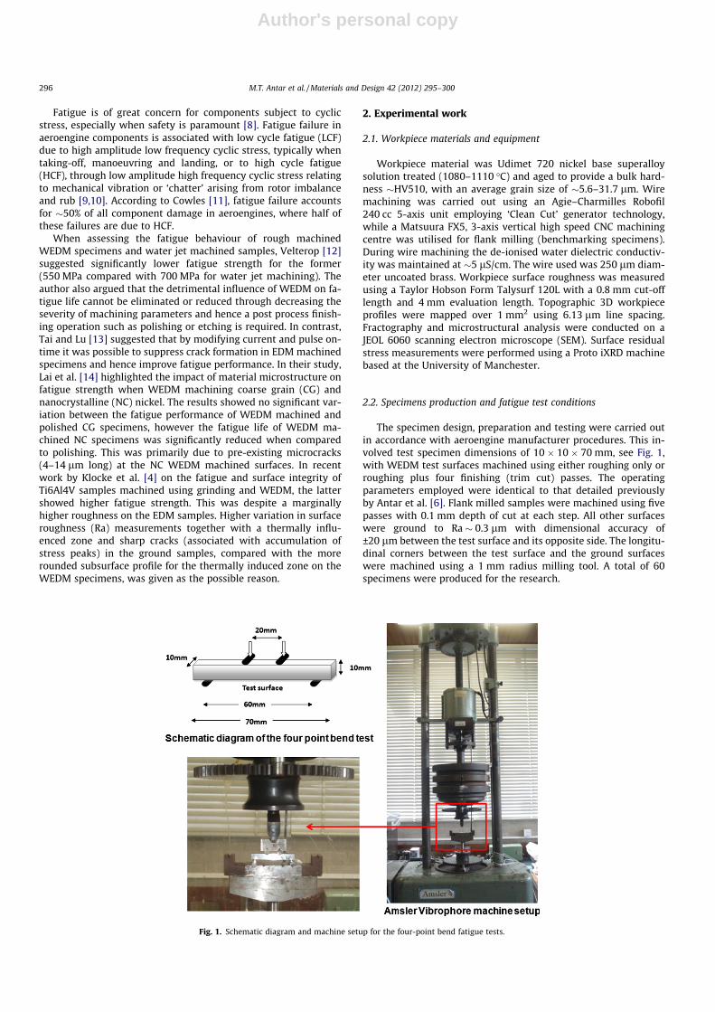
The specimen design, preparation and testing were carried outin accordance with aeroengine manufacturer procedures. This in-volved test specimen dimensions of 10 � 10 � 70 mm, see Fig. 1,with WEDM test surfaces machined using either roughing only orroughing plus four finishing (trim cut) passes. The operatingparameters employed were identical to that detailed previouslyby Antar et al. [6]. Flank milled samples were machined using fivepasses with 0.1 mm depth of cut at each step. All other surfaceswere ground to Ra � 0.3 lm with dimensional accuracy of±20 lm between the test surface and its opposite side. The longitu-dinal corners between the test surface and the ground surfaceswere machined using a 1 mm radius milling tool. A total of 60specimens were produced for the research.
Fig. 1. Schematic diagram and machine setup for the four-point bend fatigue tests.
296 M.T. Antar et al. / Materials and Design 42 (2012) 295–300

Author's personal copy
Fatigue tests were conducted using a four point bend arrange-ment which maintained maximum stresses on the test surface,see Fig. 1. All tests were performed at room temperature (20 �C)on an Amsler Vibrophore electro-magnetic resonance testing ma-chine. The test frequency varied between 75 and 84 Hz (HCF)depending on the applied stress level, with specimen run-out beingdefined as 1.2 � 107 cycles. The trials were carried out at six stresslevels with three repetitions at each, however full disclosure of theapplied stress levels is not possible due to commercial restrictions.The maximum applied load at the test surface was calculated usingthe elastic bending theory shown in Eq. (1) [15].
rmax ¼3 � Pmax � S
b � t2 ð1Þ
where Pmax is the maximum applied load, S is the distance betweenthe inner and outer rollers (20 mm), b is the specimen width(10 mm) and t is the specimen height (10 mm).
3. Results and discussion
Fig. 2 details the S–N curves for all specimens. The results showsimilar plot points for all operations, whether milling or WEDMroughing and finishing at the highest applied stress level, howeverfor lower stress values the variation is more noticeable. At interme-diate stress levels, a clear shift is evident in the response for millingsuggesting a better fatigue life. The fatigue run out of 1.2 � 107 cy-cles was recorded at �0.39 of the ultimate strength for WEDMroughing specimens, while the ratio was�0.59 for WEDM finishingand �0.65 for the milled samples. Similar fatigue strength ratios(�0.65) were also reported by Ren and Nicholas [16,17] for groundand polished Udimet 720. The S–N curves of the three processesalso suggest low variation in the number of cycles to failure atthe same stress levels, indicating consistency of the machiningoperations.
Fig. 3 shows the log10 plot for all samples. Statistical analysisinvolving t-test and regression evaluation was used to determinethe statistical differences between results for the alternative pro-cesses and whether the variations were significant. This entailedcalculating the variance for each curve (log10 values), from whichthe pooled variance for each pair of curves to be compared (e.g.milling vs. WEDM finishing) was found. Subsequently, the tcalc
values for the gradient and the intercept for each comparisoncombination were estimated and finally these values werecompared with the tabulated (ttab) figures for estimating thesignificance of statistical differences. The results showed no signif-icant differences between the slopes of the milled and WEDM fin-ishing curves at the 5% level, although the opposite was true in
terms of the intercept. The differences were significant (for bothmeasures) between WEDM roughing and both milling and WEDMfinishing, see Table 1. Since the fatigue performance after just onecycle (i.e. log10 N = 0) has no practical relevance, a subsequentregression analysis considered the intercept at log10 N = 5 (105
Fig. 2. S–N fatigue curve for Udimet 720 specimens.
Fig. 3. Log10–log10 fatigue curve plots for Udimet 720 specimens.
Table 1Statistical analysis/significance of variation between fatigue performance of Udimet720 using WEDM roughing, WEDM finishing and flank milling.
Process aspects Measure ttab
0.025
tcalc Significance
Milling vs WEDM finishing Slope 2.048 1.673 Nonsignificant
Intercept 2.048 3.340 Significant*
Intercepta 2.048 0.122 Nonsignificant
Milling vs WEDM roughing Slope 2.021 7.289 Significant*
Intercept 2.021 13.550 Significant*
WEDM finishing vsroughing
Slope 2.021 5.499 Significant*
Intercept 2.021 10.203 Significant*
* Significant at the 5% level.a Intercept at log10 N = 5 (105 cycles to failure).
Fig. 4. Surface residual stress levels for Udimet 720 fatigue specimens.
M.T. Antar et al. / Materials and Design 42 (2012) 295–300 297
Author's personal copy
cycles to failure). This highlighted no significant differences in theintercept parameters; see updated values in Table 1 (shown initalic).
The superior fatigue performance of specimens subject to fin-ishing with WEDM (Ra � 0.4 lm) compared with roughing (Ra �3.3 lm) could in part be attributed to the significantly lowersurface roughness/shallower valleys in the former, which was sim-ilar to that obtained with the flank milled samples (Ra � 0.5 lm).Novovic [18] studied the effects of machined workpiece surfacetopography on fatigue life, and found that for machined surfaces
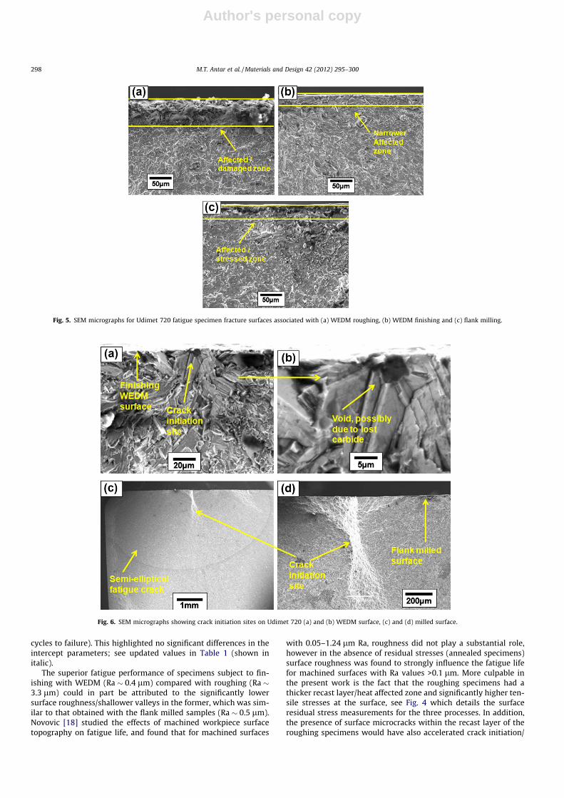
with 0.05–1.24 lm Ra, roughness did not play a substantial role,however in the absence of residual stresses (annealed specimens)surface roughness was found to strongly influence the fatigue lifefor machined surfaces with Ra values >0.1 lm. More culpable inthe present work is the fact that the roughing specimens had athicker recast layer/heat affected zone and significantly higher ten-sile stresses at the surface, see Fig. 4 which details the surfaceresidual stress measurements for the three processes. In addition,the presence of surface microcracks within the recast layer of theroughing specimens would have also accelerated crack initiation/
Fig. 5. SEM micrographs for Udimet 720 fatigue specimen fracture surfaces associated with (a) WEDM roughing, (b) WEDM finishing and (c) flank milling.
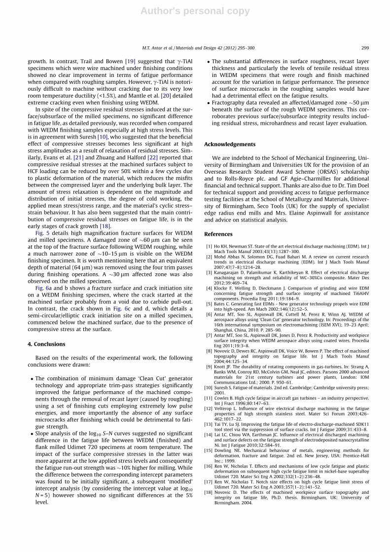
Fig. 6. SEM micrographs showing crack initiation sites on Udimet 720 (a) and (b) WEDM surface, (c) and (d) milled surface.
298 M.T. Antar et al. / Materials and Design 42 (2012) 295–300
Author's personal copy
growth. In contrast, Trail and Bowen [19] suggested that c-TiAlspecimens which were wire machined under finishing conditionsshowed no clear improvement in terms of fatigue performancewhen compared with roughing samples. However, c-TiAl is notori-ously difficult to machine without cracking due to its very lowroom temperature ductility (<1.5%), and Mantle et al. [20] detailedextreme cracking even when finishing using WEDM.
In spite of the compressive residual stresses induced at the sur-face/subsurface of the milled specimens, no significant differencein fatigue life, as detailed previously, was recorded when comparedwith WEDM finishing samples especially at high stress levels. Thisis in agreement with Suresh [10], who suggested that the beneficialeffect of compressive stresses becomes less significant at highstress amplitudes as a result of relaxation of residual stresses. Sim-ilarly, Evans et al. [21] and Zhuang and Halford [22] reported thatcompressive residual stresses at the machined surfaces subject toHCF loading can be reduced by over 50% within a few cycles dueto plastic deformation of the material, which reduces the misfitsbetween the compressed layer and the underlying bulk layer. Theamount of stress relaxation is dependent on the magnitude anddistribution of initial stresses, the degree of cold working, theapplied mean stress/stress range, and the material’s cyclic stress–strain behaviour. It has also been suggested that the main contri-bution of compressive residual stresses on fatigue life, is in theearly stages of crack growth [18].
Fig. 5 details high magnification fracture surfaces for WEDMand milled specimens. A damaged zone of �60 lm can be seenat the top of the fracture surface following WEDM roughing, whilea much narrower zone of �10–15 lm is visible on the WEDMfinishing specimen. It is worth mentioning here that an equivalentdepth of material (64 lm) was removed using the four trim passesduring finishing operations. A �30 lm affected zone was alsoobserved on the milled specimen.
Fig. 6a and b shows a fracture surface and crack initiation siteon a WEDM finishing specimen, where the crack started at themachined surface probably from a void due to carbide pull-out.In contrast, the crack shown in Fig. 6c and d, which details asemi-circular/elliptic crack initiation site on a milled specimen,commenced below the machined surface, due to the presence ofcompressive stress at the surface.
4. Conclusions
Based on the results of the experimental work, the followingconclusions were drawn:
� The combination of minimum damage ‘Clean Cut’ generatortechnology and appropriate trim-pass strategies significantlyimproved the fatigue performance of the machined compo-nents through the removal of recast layer (caused by roughing)using a set of finishing cuts employing extremely low pulseenergies, and more importantly the absence of any surfacemicrocracks after finishing which could be detrimental to fati-gue strength.� Slope analysis of the log10 S–N curves suggested no significant
difference in the fatigue life between WEDM (finished) andflank milled Udimet 720 specimens at room temperature. Theimpact of the surface compressive stresses in the latter wasmore apparent at the low applied stress levels and consequentlythe fatigue run-out strength was �10% higher for milling. Whilethe difference between the corresponding intercept parameterswas found to be initially significant, a subsequent ‘modified’intercept analysis (by considering the intercept value at log10
N = 5) however showed no significant differences at the 5%level.
� The substantial differences in surface roughness, recast layerthickness and particularly the levels of tensile residual stressin WEDM specimens that were rough and finish machinedaccount for the variation in fatigue performance. The presenceof surface microcracks in the roughing samples would havehad a detrimental effect on the fatigue results.� Fractography data revealed an affected/damaged zone �50 lm
beneath the surface of the rough WEDM specimens. This cor-roborates previous surface/subsurface integrity results includ-ing residual stress, microhardness and recast layer evaluation.
Acknowledgements
We are indebted to the School of Mechanical Engineering, Uni-versity of Birmingham and Universities UK for the provision of anOverseas Research Student Award Scheme (ORSAS) scholarshipand to Rolls-Royce plc. and GF Agie–Charmilles for additionalfinancial and technical support. Thanks are also due to Dr. Tim Doelfor technical support and providing access to fatigue performancetesting facilities at the School of Metallurgy and Materials, Univer-sity of Birmingham, Seco Tools (UK) for the supply of specialistedge radius end mills and Mrs. Elaine Aspinwall for assistanceand advice on statistical analysis.
References
[1] Ho KH, Newman ST. State of the art electrical discharge machining (EDM). Int JMach Tools Manuf 2003;43(13):1287–300.
[2] Mohd Abbas N, Solomon DG, Fuad Bahari M. A review on current researchtrends in electrical discharge machining (EDM). Int J Mach Tools Manuf2007;47(7–8):1214–28.
[3] Kanagarajan D, Palanikumar K, Karthikeyan R. Effect of electrical dischargemachining on strength and reliability of WC–30%Co composite. Mater Des2012;39:469–74.
[4] Klocke F, Welling D, Dieckmann J. Comparison of grinding and wire EDMconcerning fatigue strength and surface integrity of machined Ti6Al4Vcomponents. Procedia Eng 2011;19:184–9.
[5] Bates C. Generating fast EDMs - New generator technology propels wire EDMinto high-speed. Am Mach 2002;146(12):52–5.
[6] Antar MT, Soo SL, Aspinwall DK, Cuttell M, Perez R, Winn AJ. WEDM ofaerospace alloys using ‘Clean Cut’ generator technology. In: Proceedings of the16th international symposium on electromachining (ISEM XVI); 19–23 April;Shanghai, China, 2010. P. 285–90.
[7] Antar MT, Soo SL, Aspinwall DK, Jones D, Perez R. Productivity and workpiecesurface integrity when WEDM aerospace alloys using coated wires. ProcediaEng 2011;19:3–8.
[8] Novovic D, Dewes RC, Aspinwall DK, Voice W, Bowen P. The effect of machinedtopography and integrity on fatigue life. Int J Mach Tools Manuf2004;44:125–34.
[9] Knott JF. The durability of rotating components in gas-turbines. In: Strang A,Banks WM, Conroy RD, McColvin GM, Neal JC, editors. Parsons 2000 advancedmaterials for 21st century turbines and power plants, London: IOMCommunications Ltd.; 2000. P. 950–61.
[10] Suresh S. Fatigue of materials. 2nd ed. Cambridge: Cambridge university press;2001.
[11] Cowles B. High cycle fatigue in aircraft gas turbines – an industry perspective.Int J Fract 1996;80:147–63.
[12] Velterop L. Influence of wire electrical discharge machining in the fatigueproperties of high strength stainless steel. Mater Sci Forum 2003;426–462:1017–22.
[13] Tai TY, Lu SJ. Improving the fatigue life of electro-discharge-machined SDK11tool steel via the suppression of surface cracks. Int J Fatigue 2009;31:433–8.
[14] Lai LC, Chiou WA, Earthman JC. Influence of electrical discharged machiningand surface defects on the fatigue strength of electrodeposited nanocrystallineNi. Int J Fatigue 2010;32:584–91.
[15] Dowling NE. Mechanical behaviour of metals, engineering methods fordeformation, fracture and fatigue. 2nd ed. New Jersey, USA: Prentice-HallInc.; 1999.
[16] Ren W, Nicholas T. Effects and mechanisms of low cycle fatigue and plasticdeformation on subsequent high cycle fatigue limit in nickel-base superalloyUdimet 720. Mater Sci Eng A 2002;332(1–2):236–48.
[17] Ren W, Nicholas T. Notch size effects on high cycle fatigue limit stress ofUdimet 720. Mater Sci Eng A 2003;357(1–2):141–52.
[18] Novovic D. The effects of machined workpiece surface topography andintegrity on fatigue life, Ph.D. thesis. Birmingham, UK: University ofBirmingham. 2004.
M.T. Antar et al. / Materials and Design 42 (2012) 295–300 299

Author's personal copy
[19] Trail SJ, Bowen P. Effects of stress concentrations on the fatigue life of agamma-based titanium aluminide. Mater Sci Eng A 1995;192–193(Part1):427–34.
[20] Mantle AL, Abboud E, Aspinwall DK. Productivity and workpiece surfaceintegrity effects when WEDM-ing a gamma titanium aluminide. In:Proceedings of the 14th conference of the Irish manufacturing committee(IMC-14); 3–5 September; Dublin, Ireland, 1997. p. 443–50.
[21] Evans A, Kim SB, Shackleton J, Bruno G, Preuss M, Withers PJ. Relaxation ofresidual stress in shot peened Udimet 720Li under high temperatureisothermal fatigue. Int J Fatigue 2005;27:1530–4.
[22] Zhuang WZ, Halford GR. Investigation of residual stress relaxation under cyclicload. Int J Fatigue 2001;23(Suppl. 1):31–7.
300 M.T. Antar et al. / Materials and Design 42 (2012) 295–300