fatigue evaluation of composite … contractor report nasa cr-2136 fatigue evaluation of...
TRANSCRIPT

N A S A C O N T R A C T O R
R E P O R T
N A S A C R - 2 1 3 6
FATIGUE EVALUATION OFCOMPOSITE-REINFORCED, INTEGRALLY
STIFFENED METAL PANELS - SUMMARY
by C, E. Dumesnil
Prepared by
VOUGHT AERONAUTICS COMPANY
Dallas, Texas
for Langley Research Center
NATIONAL AERONAUTICS AND SPACE ADMINISTRATION • WASHINGTON, D. C. • FEBRUARY 1973
https://ntrs.nasa.gov/search.jsp?R=19730008182 2018-05-21T11:11:47+00:00Z

1. Report No.NASA CR-2136
2. Government Accession No. 3. Recipient's Catalog No.
4. Title and Subtitle
FATIGUE EVALUATION OF COMPOSITE-REINFORCED, INTEGRALLYSTIFFENED METAL PANELS—SUMMARY
5. Report Date
February 1973
6. Performing Organization Code
7. Author(s)
C. E. Dumesnil
8. Performing Organization Report No.
9. Performing Organization Name and Address
Vought Aeronautics Company
Dallas, Texas
10. Work Unit No.
737-5U-12-CA-2311. Contract or Grant No.
NAS1-10871
12. Sponsoring Agency Name and Address
National Aeronautics and Space AdministrationWashington, D.C. 205U6
13. Type of Report and Period Covered
Contractor Report
14. Sponsoring Agency Code
15. Supplementary Notes
This report summarizes material presented in NASA CR-112ll*8
16. Abstract
The fatigue and fail-safe behavior of composite-reinforced, integrally stiffened metal panels
was investigated. Test results consisting of conventional fatigue lives, fatigue-crack-
propagation rates, and residual static strength are presented and discussed.
17. Key Words (Suggested by Author(s))
Integrally stiffened panelComposite reinforcementFatigueCrack propagationResidual static strengthTesting
18. Distribution Statement
Unclassified - Unlimited
19. Security dassif. (of this report)
Unclassified
20. Security Classif. (of this page)
Unclassified
21. No. of Pages
31
22. Price*
$3.00
For sale by the National Technical Information Service, Springfield, Virginia 22151

TABLE OF CONTENTS
Page No.
SUMMARY 1
INTRODUCTION 3
SYMBOLS 5
DESIGN CRITERIA 7.
TEST SPECIMENS 9
Fatigue Coupons 9
Composite-Reinforced Panels 9
TEST PROCEDURE 11
RESULTS AND DISCUSSION 13
Coupon Fatigue Tests 13
Composite-Reinforced Panel Tests 13
CONCLUSIONS 15
APPENDIX - Conversion of U. S. CustomaryUnits to SI Units 1?
REFERENCES 19
iii

FATIGUE EVALUATION OF COMPOSITE-REINFORCED,
INTEGRALLY STIFFENED METAL PANELS - SUMMARY
By C. E. DumesnilVought Aeronautics Company
SUMMARY
This summary report gives the salient results of an investigation of thefatigue and fail-safe behavior of composite-reinforced, integrally stiffenedmetal panels. The test methods, fabrication procedures, material descriptions,and complete test results are given in reference 1.
The panels were made by introducing unidirectional composite materialbetween the aluminum face sheets of an integrally formed, stiffened panel. Bothgraphite/epoxy and S-glass/epoxy composites with an elevated-temperature-cureadhesive were used; some additional graphite/epoxy panels were made with a room-temperature-cure adhesive to determine the effects of residual thermal stresses.The panels were tested at various stress levels with constant-amplitude fatigueloads. Crack growth rates were measured in the aluminum face sheets and comparedwith rates in an all-metal panel. After the fatigue tests, the panels werestatically loaded to failure to measure their residual strength.
Conventional fatigue tests were also conducted on simple coupon specimensof similar construction to measure the fail-safe characteristics of the composite-metal system.
The results indicate that a composite-reinforced metal panel can be designedto have a residual strength higher than the design limit load after significantfatigue cracks have developed in the metal, and have no more mass than an all-metal panel.

INTRODUCTION
An effective fail-safe structural concept, which has application forpresent and future aircraft systems such as the space shuttle and advancedtechnology transports, has been evaluated in this research effort. The all-metal, integrally-formed panel concept has shown considerable potential forimproving aerospace structures in terms of low manufacturing cost, high-strengthcapability, low weight, and inherent fail-safe compression failure character-istics (reference 2). The inclusion of advanced composite material between thetwo sheets of the integrally-formed panel reduces metal fatigue crack growth andincreases residual strength at no increase in mass. .A-composite-reinforced,integrally-stiffened metal panel is shown in Figure 1.
The all-metal integrally-formed panel (figure l) consists of two sheets ofmetal bonded together: (1) a flat outer sheet and (2) an integrally formed andstiffened inner sheet. This panel configuration offers a significant increasein the Strength-weight index as compared to the conventional riveted Z panelsof the same material and design conditions. By inserting unidirectionalcomposite material between the inner and outer sheets, the composite-reinforced,integrally-stiffened metal panel concept is obtained.
This program investigated the fatigue and fail-safe behavior of thisstructural concept. Coupon specimens were fabricated and tested in statictension and fatigue to demonstrate the fail-safe characteristics of the composite-metal system. Fifteen composite-reinforced, integrally-stiffened metal panelswere fabricated and tested in tension-tension fatigue to determine the metal crackgrowth rates and panel residual strengths. The panels were made from 7075-T6aluminum alloy and reinforced with either graphite/epoxy or S-glass/epoxy usingan elevated-temperature-cure adhesive. Some panels were also made with graphite/epoxy using a room-temperature-cure adhesive in order to determine the effectsof residual thermal stresses.

Page Intentionally Left Blank

SYMBOLS
The physical quantities in this report are given in both the InternationalSystem of Units (Si) and in the U. S. Customary Units. The SI units are statedfirst and the customary units afterwards, in parentheses. All principalmeasurements and calculations were made in the U. S. Customary Units. TheAppendix to this report presents factors relating these two systems of units.
2a total crack length, mm. (in.)
2 2A total gross cross-sectional area, m (in. )n
E modulus of elasticity, MN/m (ksi.)n
f gross stress, MN/m (ksi.)P
F gross allowable stress, MN/m (ksi.)
Ki. stress concentration
N number of cycles of load
P load, N (Ibf.)
K ratio of minimum to maximum values of cyclic load
t thickness, mm. (in.)
W weight, kg (ibm.)
€ strain
H ratio of composite stiffness to total stiffnesso o
P density, kg/m (ibm./in-5)
Subscripts
am all metal
c composite
c-m composite-metal
m metal
max maximum

SYMBOLS (Cont)
Subscripts
t total
tl tension limit
tu tension ultimate

DESIGN CRITERIA
The following design criteria were selected to provide a fail-safe struc-ture that would weigh no more than an all-metal structure.
(1) The composite material alone shall support the total limit loadassuming the metal to be completely failed.
(2) The mass of the composite-reinforced panel shall be equal to thatof an all-metal panel designed to support the same limit load.
(3) Design stresses at limit load shall be two-thirds of ultimate allow-able stresses. (See Table I.)
Because of the limited scope of this investigation, consideration was notgiven to biaxial and shear properties and joint requirements. Such consider-ations would be necessary to select the minimum gage of metal and thus the •minimum weight.
Assuming the metal and composite material to strain equally, the strain ineither material is
Pm Pc€ = . E . = T-= - (1)
AmEm AcEc
Defining a stiffness ratio " fi " for the composite-metal system as
AoEnH = - - - (2)
AcEc+AmEm . . ,
the total load on the composite-metal system would distribute as
Pc ' " Pt » Pm ' (1- " ) Pt
The weight of a composite-metal structure for a unit length is
W = P A . + P Ac-m c c mm
and the weight of an all-metal structure is

Setting the weight of the composite-metal system equal to the weight of the all-metal jtructure, condition (2) of the design criteria,
P A + p A = P A (6)c c mm m am
or •
A ~ A ~ pc c ym
Substituting (?) into (2),
H = _ 1 _ (8)E 3 p
1 + ( JS-) (-& - -S.)Ec c Pm
To satisfy condition (l) of the design criteria, the composite must carry thetotal limit load when the metal fails. Thus,
A - *c ~ -PF
To satisfy condition (2) of the design criteria, the all-metal system must alsocarry the total limit load. Thus,
V • fe- <*»m
Substituting (9) and (10) into (8), the stiffness ratio becomes
m
Using the properties in Table I, Equation (ll) gives H =0.57 for thegraphite panel and H =0.29 for the S-glass panel.
8

TEST SPECIMENS
Fatigue Coupons
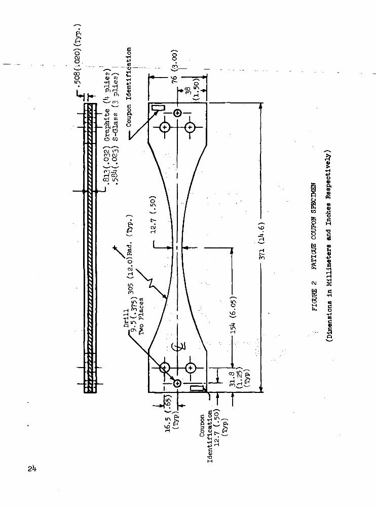
Sixty-six fatigue coupons were fabricated as shown in Figure 2. Thesespecimens consisted of all-aluminum control specimens, aluminum-graphite, andaluminum-glass specimens bonded with AF-126 adhesive (elevated temperature cure)and aluminum-graphite specimens bonded with EA-927R adhesive (room temperaturecure). Half of these specimens contained a 3.2 mm (0.125 in.) diameter hole toprovide a stress concentration factor greater than one.
The all-aluminum control specimens were fabricated from 1.02 mm (0.00 in.)thick 7075-T6 aluminum. The stiffness ratio was H =0.57 for the aluminum-graphite coupons and fi = 0.29 for the aluminum-glass coupons.
Compos it e-Heinf or ced Panels
One all-metal, integrally-stiffened panel was fabricated from 7075-T6aluminum. The inner and outer sheets were each 0.51 mm (0.020 in.) thick andbonded together with AF-126 adhesive (39U°K (250°F) cure).
Fourteen composite-reinforced, integrally-stiffened metal panels werefabricated. These consisted of six aluminum-graphite panels bonded with AF-126adhesive, four aluminum-glass panels bonded with AF-126 adhesive, and fouraluminum-graphite panels bonded with EA-927R adhesive. The configuration ofthese panels is shown in Figure 3. The stiffness ratios for these panels areU =0.57 for the aluminum-graphite panels and fl =0.29 for the aluminum-glasspanels.
Each panel was 762 mm (30 in.) long, 305 mm (12 in.) wide, and necked downto 2Ul mm (9.5 in.) at the test section. Panels 1C, 3C, and 8C were not neckeddown at the test section. A crack starter hole, 6.4mm. (0.25 in.) diameter,was drilled in the center of the panel. Individual fittings were bonded andbolted to each end of the panels to provide attachment to the testing machine.

Page Intentionally Left Blank

TEST PROCEDURE
All of the coupons and panels were subjected to axial tension-tensionfatigue loading of constant amplitude and load ratio R of 0.10. The grossstress in the metal stiffener and face sheets and composite materials wascalculated in terms of the total applied load using Equations (2) and (3).
The fatigue coupons were tested at several stress levels at a frequency of30 HZ.(1800 cpm). The number of cycles required for the failure of the metaland the composite material respectively were recorded.
The panels were tested at several stress levels and at frequencies rangingfrom 1 to 10 HZ (60 to 600 cpm). The number of cycles required to initiate acrack in the metal at the test-section hole was recorded. A paper grid withlines spaced at 1.27 mm (0.05 in.) was attached to the panel in line with theprimary cracks in the panel test section. A 30- powered transit with crossedhair-lines <and mounted on adjustable stands was used to make crack lengthmeasurements every 1.27 mm (0.05 in.). There were primarily four cracks tomonitor, a crack to each side of the panel centerline on both the stiffenerand face sheet sides.
n

RESULTS AND DISCUSSION
Coupon Fatigue Tests
Figures If, 5, and 6 show curves of maximum stress against cycles to failurefor the coupons with the various composite-metal-adhesive systems. The curvesshow the cycles to failure for the metal and the additional cycles.to failure •for the composite material. The metal always failed first. The stresses shownfor the composite materials are calculated assuming the metal to be failed.(The ratio of stress in the composite material before and after the metal failsis given by the ratio I/ft . Thus, for the graphite-reinforced coupons, thestress after failure is 1.78 times the stress before failure and for the glass-reinforced coupons 3.1*5 times the stress before failure.) Conventional fatiguecurves are also shown for the 7075-T6 aluminum alloy with K. = 1.0 and Kj. = 2.U.The value of K . = 2.1* was calculated (reference 3) for the hole neglecting theeffects of the composite reinforcement. Curves are faired through the compositematerial data for convenience.
The cycles to failure of the metal in the graphite-reinforced coupons withKx. = 1.0 are somewhat larger for the room-temperature-cure adhesive than theelevated-temperature-cure adhesive. This is due to the residual tensile stressesin the metal caused by the elevated temperature cure. Otherwise, the lives .ofthe metal in the composite-reinforced coupons generally agree with the conven-tional fatigue curves, and, thus, the composite reinforcement has little effecton the stress concentration factor and the life of the metal.
. The curves also show that the graphite-reinforced coupons have exceptionalfatigue life after failure of the metal, even at stresses much above the allow-able limit stress. The glass-reinforced coupons also have considerable fatiguelife after failure of the metal but much less than the graphite-reinforcedcoupons.
The total life of each of the test specimens can be found in reference 1.
Composite-Reinforced Panel Tests
Figure 7 shows the growth of the crack in the outer face sheet at threedifferent stress levels in the metal for the three composite-metal-adhesivesystems. The crack length (2a) in the outer face "sheet (see-figure 3) and thenumber of cycles are plotted starting at a crack length (2a) of 25. U mm (1.0 in.),For convenience, the results for each stress level are contained by a shadedband. (The growth of the crack in the inner face sheet was similar and isreported in detail in reference 1.) For comparison, the results for the all-metal panel are also shown.
The results show that the composite reinforcement greatly reduces the rateof crack growth when compared with the all-metal panel. Also, the rate in thecomposite-reinforced panels increases with increasing stress but is essentiallyconstant with respect to crack length. Thus, the stresses in the vicinity of
13

Page Intentionally Left Blank

the crack tip do not increase with increasing crack length as in the case of theall-metal panel. The results also sjiow that the rate of crack growth in thegraphit e reinforceli""parrel is~less 'than irTthe glass-reinforced panel. Thisis likely due to the heavier reinforcement by the graphite as indicated by thelarger value of H . The difference in crack growth rates between the panelswith elevated-temperature-cure and room-temperature-cure adhesive is inconsistentand generally not significant.
After the fatigue cracks were grown one-fourth to one-half the width of thepanels, the panels were statically loaded to failure to determine the residualstrength. The results are shown in Table II along with the fatigue stress, thetotal number of cycles, and the proportion of metal cracked for each panel, Theresults show that the residual strength of the panels generally exceeded thedesign limit load and, thus, satisfied the design criteria. (Two of the threepanels that failed to meet the criteria failed at the end fittings.) However,some degradation of original composite strength due to fatigue is indicatedbecause the residual strengths are generally less than the original ultimatestrength (150$ limit strength).
:\

CONCLUSIONS
The fatigue tests of the composite reinforced coupons showed that thecomposite reinforcement generally had little effect on the stress concentrationfactor for a 1/8 inch diameter hole and the cycles to failure of the metal. Thegraphite-reinforced and the glass-reinforced coupons had considerable fatiguelife after failure of the metal with the graphite-reinforced coupons having a -much higher fatigue strength than the glass-reinforced coupons.
The crack growth tests of the composite-reinforced, integrally stiffenedpanels showed that the composite reinforcement greatly reduced the rate ofcrack growth in the metal when compared with an all-metal panel. The rate ofcrack growth was constant with increasing crack length. Thus, the compositereinforcement prevented the stresses in the vicinity of the crack tip fromincreasing with increasing crack length as was the case in the all-metal inte-grally formed panel. The rate of crack growth in the graphite-reinforced panelswas less than in the glass-reinforced panels. This can probably be attributedto the graphite reinforcement being stiffer than the glass reinforcement.
The residual strength tests of the composite-reinforced, integrallystiffened panels showed that the strength of the panels exceeded the designlimit load after much of the metal had failed under fatigue loading.
The results were not significantly different for the room-temperature-cure adhesive and the elevated-temperature-cure adhesive.
In general, the results of this program indicate that composite reinforce-ment of integrally formed metal panels can provide, without a weight penalty,considerable fail-safe strength after much fatigue damage to the metal. Futurestudies should improve" the design criteria to include biaxial and shear proper-ties, joint requirements, and weight minimization.
15

Page Intentionally Left Blank

APPENDIX
CONVERSION OF SI UNITS TO U. S. CUSTOMARY UNITS
~~ The International System of Units (Si) was adopted by the Eleventh
General Conference on Weights and Measures held in Paris in 1960. Con-
version factors required for .units used herein are given in the following
table:
Physical Quantity
Density
Force
Length
Mass
Stress, Modulus
Temperature
SI Unit(*)
kilograms per cubic meter
(kg/m3)
newtons (N)
meters (m)
kilograms (kg)
newtons per sq. meter
(N/m2)
degrees Kelvin (K)
Conversionfactor(**)
0.3613 x 10
0.22 8
0.3937 X IO2
2.205
0.11*5 x io"6
|K- 1+59.67
U.S. CustomaryUnit
lbm/in3
Ibf
in.
Ibm.
ksi = IO3 lbf/in2
°F
Prefixes to indicate multiple of units are as follows:
Prefix
mega (M) __. .
- kilo (k)
nilli (m)
Multiple
IO3
**Multiply value given in SI Unit by conversion factor to obtain
equivalent in U. S. Customary Unit.
17

REFERENCES
1. C. E. Dumesnil: Fatigue Evaluation of Composite-ReinforcedIntegrally Stiffened Metal Panels., NASA CR-1121 8, 1972.
2. J. C. McQueen, S. W. McClaren, and A. P. Martin: IntegrallyFormed Structures: A New Stiffened Panel Concept, Journal ofAircraft, Vol. 7, No. 6, Nov. Dec., 1970, pp. ~
3. R. -E. Peterson, Stress Concentration Design Factors, John Wiley, &Sons, Inc., New York, 1953- >
'19

Page Intentionally Left Blank

TABLE I
DESIGN PROPERTIES OFMETAL AND COMPOSITE MATERIALS
MATERIAL
7075 -T6 Aluminum
Graphite/Epoxy(HT/S)
S -Glass Epoxy(1009-26S)
LIMIT STRESS
MN/m2
359
696
986
(ksi)
52
101
1 3
TENSION MODULUS
MN/m2
71,000
131,000
61,000
(ksi)
10,300
19,000
8,900
DENSITY
kg/m3.
2768
1550
1882
(Ibm/in3)
0.100
0.056
0.068
21

H
M g
*• ti^5 35
vi J
iii** tgt~i p3
(X CO
EH
3 oM ^asa
I!M
j§ W
8
P« ^° 65
sS
3
£5b w
S co
Wg 3
<rT
SX
fcl-l
3
fO^
SM
fci-l
§
%^^
^
CO
•rl
At
cvj^
1<
IACM
t-•
r-lrH
CVJ•
CVJIA
IA
3
CO.•
SA^^CO
mH^N
^
CO
£S
o£
S
d33|
CO C\J O W 1 CMrH r-l r-l 1 r-t
CM o cn o c?O CM C^ CO /h\ H
.ITN CO ir\ VD — CM
CO t— CO ITV r-(* * * * /\ *ro ^t ro CM XA o\
CM m CM ro in
vo ir\ vo vo vo voVO irv vD vo vO vOITN \D IA IA 1T\ ITS
CO CO GO CO CO CO
1A ON IA IA VA IAC\J CM W CM CVJ CM
\@ o v^ v£ vo vOc5 oo o c^ CO C5vo ^t VO VD vO VOIA VO IA IA LA IA
vO O VD VO VO vOr-t CO i-l r-l rH r-tVO r-l VD VO VO VOm j- m co m ro
r-l VO W CO IA VDJ- CVJ W CVJ CVJ ro
CVJ VO J- CVJ t Oit Q CO IA CJ\ CVJCO VD H J" CO IA
O~\ IA ^ VO J- Ot^ vo o c- IA cye- j- fo H cu o
r-l
CTv ON ON O O OVO VD VO IA P IAr-l r-l i-l CM CVJ iH
vo vo vo Cvj co ror-l i-l rH t- CO OH r-l rH H r-l rH
•aa; v *~* o>-P O W fn >•H t-i 4) -H^ OO O (H CO^tH-* O 3 4)at q OMA o AIt -rl OO CM !3Og ^ <
t- CM CO Cf\
,3 21 3 S
o IA m o\• • • •
O VD VD tA
t— ON ON IA• • • •
ro vo VD t-IA CO t~ IAJ- CVJ CVJ CM
O ON CT\ CTN
H CVJ CM CMVO IA IA IA
ro ro ro ro• • • •
i-l IA IA IAt-- ro ro roCVJ CM CM CVJ
t ro ro oo
O ON ON CT\IA f- t- r-t- ro ro roCM . CM CM CM
ro ro ro OJ- IA IA _*
ON ON ro voCM ^ CO t-IA O ON 9-
Jt rH rH VOIA ro J- pIA vD ro CM
O O O OIA IA O IAi-l r-l CM CM
ro ro co CMS S 2 5
T3M a> x— > ajw o « fe !>a) ^ D *HH OO O i-i WC3 <M J- O 3 0)i d ONIAO ,g
co -3 ro CM *3& ~ <
^ r^ ^ 3
O VO CO O• • • •t- ro CVJ ONIA CO vD h-
IA CO ro -* .* • * •
ro rH O\ rHIA t f- 1ACvj ro CM ro
IA IA IA VD
IA IA IA VOVO VO VO IA
ro ro ro CO• • • •H rH i-H HON ON OS IACVJ CM CM CM
CO CO CO O
vo VD VD IA
o o o voCO OO CO rHi-H rH rH VOJt J- J- PO
AAA.
ro co C^- tA'ON O ON VOON 3 CO J-
CM ro O VOIA IA ro oCM CO IA IA'
MH
O O O ONIA IA P VOCM H CM H
CM ro CO VO
r7 S r? rl
HI 0) 0)+3 O • >•H h S ft a> -HJS O O H rl COtt£ o 3 3 a)S 5 K H 6 - §o « <:
22

23
CVJ
-PO
2
a1a
I
en
§•Ha

305 (12.0)
(9.5)
381 (15.0)
6.H (.25)Dia. Hole
—.813(.032) Graphite (4 plies)-,.58M.023) S-Glass (3 plies)
Fatigue Crack
16 (.625)
.51 (-020)
Section A-A
Figure 3 Composite-Reinforced, Integrally Stiffened Metal Panel(Dimensions in Millimeters and Inches, Respectively)
25

-o —H
P
. ^
?
P
C*-
H
*!'•H C40 "a
-*•-cOB
.p
.
"
. •
.
•
*b
1
"s
,
— j
I
eg«)i-l
. ' X"O
"2>
o 1
s•o
r, J< "«K VO ft "I T « t^
gfc
26

s13 00
Ixwn
27

8
t> f> OO CO >
co 4-i i
rf O*vw P w"IvD .
28
XOT

oC\J 8 S
saaiawmiwS
H10N37 XOVHO
NASA-Langley, 1973 32

NATIONAL AERONAUTICS AND SPACE ADMINISTRATION
WASHINGTON. D.C. 2O546
OFFICIAL BUSINESS
PENALTY FOR PRIVATE USE S3OO SPECIAL FOURTH-CLASS RATEBOOK
POSTAGE AND FEES PAIDNATIONAL AERONAUTICS AND
SPACE ADMINISTRATION451
POSTMASTER : If Undeliverable (Section 158Postal Manual) Do Not Return
"The aeronautical and space activities of the United States shall beconducted so as to contribute . . . to the expansion of human knowl-edge of phenomena in the atmosphere and space. The Administrationshall provide for the widest practicable and appropriate disseminationof information concerning its activities and the results thereof."
—NATIONAL AERONAUTICS AND SPACE ACT OF 1958
NASA SCIENTIFIC AND TECHNICAL PUBLICATIONSTECHNICAL REPORTS: Scientific andtechnical information considered important,complete, and a lasting contribution to existingknowledge.
TECHNICAL NOTES: Information less broadin scope but nevertheless of importance as acontribution to existing knowledge.
TECHNICAL MEMORANDUMS:Information receiving limited distributionbecause of preliminary data, security classifica-tion, or other reasons. Also includes conferenceproceedings with either limited or unlimiteddistribution.
CONTRACTOR REPORTS: Scientific andtechnical information generated under a NASAcontract or grant and considered an importantcontribution to existing knowledge.
TECHNICAL TRANSLATIONS: Informationpublished in a foreign language consideredto merit NASA distribution in English.
SPECIAL PUBLICATIONS: Informationderived from or of value to NASA activities.Publications include final reports of majorprojects, monographs, data compilations,handbooks, sourcebooks, and specialbibliographies.
TECHNOLOGY UTILIZATIONPUBLICATIONS: Information on technologyused by NASA that may be of particularinterest in commercial and other non-aerospaceapplications. Publications include Tech Briefs,Technology Utilization Reports andTechnology Surveys.
Details on the availability of these publications may be obtained from:
SCIENTIFIC AND TECHNICAL INFORMATION OFFICE
N A T I O N A L A E R O N A U T I C S A N D S P A C E A D M I N I S T R A T I O N
Washington, D.C. 20546