fate of the cenozoic farallon slab from a comparison of
TRANSCRIPT

Fate of the Cenozoic Farallon slab from a comparison ofkinematic thermal modeling with tomographic images
Christian Schmid �, Saskia Goes, Suzan van der Lee, Domenico GiardiniInstitute of Geophysics, ETH Ho«nggerberg (HPP), 8093 Zu«rich, Switzerland
Received 28 May 2002; received in revised form 11 September 2002; accepted 18 September 2002
Abstract
After more than 100 million years of subduction, only small parts of the Farallon plate are still subducting belowwestern North America today. Due to the relatively young age of the most recently subducted parts of the Farallonplate and their high rates of subduction, the subducted lithosphere might be expected to have mostly thermallyequilibrated with the surrounding North American mantle. However, images from seismic tomography show positiveseismic velocity anomalies, which have been attributed to this subduction, in both the upper and lower mantle beneathNorth America. We use a three-dimensional kinematic thermal model based on the Cenozoic plate tectonic history toquantify the thermal structure of the subducted Farallon plate in the upper mantle and determine which part of theplate is imaged by seismic tomography. We find that the subducted Farallon lithosphere is not yet thermallyequilibrated and that its thermal signature for each time of subduction is found to be presently detectable as positiveseismic velocity anomalies by tomography. However, the spatially integrated positive seismic velocity anomalies intomography exceed the values obtained from the thermal model for a rigid, continuous slab by a factor of 1.5 to 2.0.We conclude that Farallon fragments that subducted since 50 to 60 Ma are still residing in the upper mantle and mustbe heavily deformed. The deformation of the slab in the transition zone is probably caused by the same mechanismsthat were responsible for flat subduction around 60 Ma.1 2002 Elsevier Science B.V. All rights reserved.
Keywords: Farallon plate; thermo-kinematic modeling; subduction; tomography; upper mantle
1. Introduction
O¡ the west coast of North America the Far-allon plate subducted during most of the Meso-and Cenozoic. The evolution of oceanic tectonicplates at the surface is well known from the anal-
ysis of magnetic patterns on the ocean £oor, incombination with geological observations onoverriding plates. However, the evolution of theseplates after their subduction is much less wellknown and is only inferred indirectly from tomo-graphic images of the present seismic structure ofEarth’s mantle and from numerical and laborato-ry experiments. A qualitative comparison of to-mographic images with the plate tectonic historyof the Farallon plate subducting beneath theNorth American plate has enabled rough esti-
0012-821X / 02 / $ ^ see front matter 1 2002 Elsevier Science B.V. All rights reserved.PII: S 0 0 1 2 - 8 2 1 X ( 0 2 ) 0 0 9 8 5 - 8
* Corresponding author. Tel. : +41-1-633-2907;Fax: +41-1-633-1065.E-mail address: [email protected] (C. Schmid).
EPSL 6439 11-11-02 Cyaan Magenta Geel Zwart
Earth and Planetary Science Letters 204 (2002) 17^32
www.elsevier.com/locate/epsl

mates of which part of the subducted plate is atwhich position in the mantle today [1,2]. A morequantitative comparison, involving numericalmodeling, has been made for the Mesozoic sub-duction [3]. Here we extend a study by Van derLee et al. [4], involving plate tectonic history, seis-mic tomography, and numerical modeling, toidentify the present position in Earth’s mantle ofthe Farallon lithosphere that subducted duringthe Cenozoic.
During this time the mid-oceanic ridge thatforms the western boundary of the Farallon plateand the Farallon^North America trench movedtowards each other and eventually met. Onlysmall segments of the Farallon plate remain atthe surface today (Fig. 1). The largest of theseremnants are the Juan de Fuca, Cocos and Nazcaplates. Most of the North American west coast isnow bordered by the Paci¢c plate. With the arriv-al of part of the ridge at the trench as of 30 Ma,subduction started to be replaced by Paci¢c^North America transform motion. This led tothe formation of a window in the subductedslab [5]. The ¢nal stages of subduction were ac-companied by a decreasing age of the subductingFarallon plate and decreasing subduction veloc-ities [6,7]. It is unclear whether this part of the
subducted Farallon lithosphere would still havea thermal signature in the mantle today.
Severinghaus and Atwater [8] inferred the ther-mal state of the subducted Farallon plate by two-dimensional mapping of a thermal parameter,which is a function of the time since subductionand age upon subduction, using the analyticalthermal model of McKenzie [9]. They concludedthat away from the still actively subducting por-tions, the Farallon plate should be thermallyequilibrated with the surrounding North Ameri-can upper mantle. However, positive seismic ve-locity anomalies in the transition zone (Figs. 2and 3) below North America suggest that thereare subducted fragments of the Farallon plate inthe upper mantle that are still a few hundred de-grees colder than the surrounding mantle [2].
The high velocities imaged in the transitionzone below the western USA form a more orless continuous feature with high velocities im-aged in the lower mantle [1] (Grand, personalcommunication, 2001) below the central and east-ern US (Fig. 3). The lower mantle anomalies havebeen associated with the subducted Farallon plate.Dynamic models of mantle convection with im-posed plate velocities at the surface give thermalanomalies that correlate well with seismic anoma-lies seen in the lower mantle [3,10]. These globalstudies do not address the smaller scale anomaliesimaged in the transition zone.
Our objective is to model the present thermalsignature of the Farallon plate in the upper man-tle. We investigate to what extent the subductedplate is thermally equilibrated with the surround-ing mantle and how much of it could be detect-able by seismic tomography. To obtain the ther-mal structure we use a kinematic model in three-dimension, based on the history of plate motionsand reconstructed plate ages. The resulting ther-mal structure is converted to seismic velocitystructure. The tomographic resolvability of thesynthetic velocity structure is then tested and thethermal velocity model is compared with the to-mographic model NA00 [11,12]. A similar ap-proach has been previously applied to the Medi-terranean region and Indonesia [13,14]. Thequantitative comparison of the tomography andthe thermal model allows us to determine which
Fig. 1. Map of the study area. Abbreviations: NA, NorthAmerican plate; PAC, Paci¢c plate; COC, Cocos plate; JdF,Juan de Fuca plate; SW, the approximate present extent ofthe slab window, assuming a 0‡ slab dip. Triangles markpresently active subduction zones. Lines show past positionsof the Farallon^Paci¢c ridge relative to a ¢xed North Ameri-ca from 60 to 10 Ma, derived from the digital age map ofMu«ller et al. [17] and the poles of Norton [16].
EPSL 6439 11-11-02 Cyaan Magenta Geel Zwart
C. Schmid et al. / Earth and Planetary Science Letters 204 (2002) 17^3218

part of the Farallon plate is actually imaged in theupper mantle below North America. Constraintson the location and amount of subducted materialin the upper mantle help to understand the dy-namics of the slab in the transition zone.
2. Model constraints
As input for the kinematic thermal model weneed plate velocities, plate ages at the trench andthe subduction geometry. Constraints on the ¢rsttwo come from plate tectonic reconstructions forthe past 60 Myr, which is su⁄cient to analyze theupper mantle part of the subducted Farallonplate. The geometry of subduction will be dis-cussed in Section 3.
2.1. Plate kinematics
We calculate the Euler poles of the Farallonplate relative to a ¢xed North America by com-bining the poles for the Paci¢c^Farallon spread-ing [15] with the Paci¢c^North America globalplate circuit poles of Norton [16]. The poles ofRoyer et al. [15] were used because of their con-
sistency with the age grid of Mu«ller et al. [17] usedfor deriving plate ages. We assume that spreadingoccurred symmetrically. By using one singlespreading pole for every point in time, we ignorethe fact that the Farallon plate broke up after theridge met the trench. This is justi¢ed since themovements of the plate fragments were similaruntil V15 Ma [18]. Furthermore, due to theslab window formation, there are only poles avail-able for the northern and the southern parts butnot for the central part of the subduction and thesimplest kinematic scenario is the assumption of asingle coherent plate.
In order to calculate the Farallon velocities rel-ative to North America, it is necessary to ¢rstde¢ne the trench location. This location is notcoincident with the present west coast of NorthAmerica, due to around 300 km of Basin andRange extension in the middle and late Cenozoic[19]. Severinghaus and Atwater [8] reconstruct theposition of the trench for several points in time.We use their location at 30 Ma, shown in Fig. 2,which is a reasonable average position for thepast 60 Myr. The southern end of this trench ex-
Fig. 3. Combined cross section through the tomographicS-velocity models NA00 [11,12] (above 660 km) and themodel of Grand [1] (Grand, personal communication, 2001;below 660 km). Bold lines mark the 660 km and the 400 kmdiscontinuity. Velocity anomalies are relative to PEM-C [46]in the upper mantle, to PREM [36] in the lower mantle. Thecolor scale is saturated for stronger anomalies than + or31.5% as occur in the uppermost mantle.
Fig. 2. Horizontal section at 500 km depth through NA00[12]. Line with triangles marks the trench location used inthe kinematic model. The line with dots (at 10‡ intervals)shows the location of the cross section in Fig. 3.
EPSL 6439 11-11-02 Cyaan Magenta Geel Zwart
C. Schmid et al. / Earth and Planetary Science Letters 204 (2002) 17^32 19
tends to the North America^Cocos (Rivera)^Pa-ci¢c triple junction, while the northern end liesnear the North America^Juan de Fuca^Paci¢c tri-ple junction (Fig. 2).
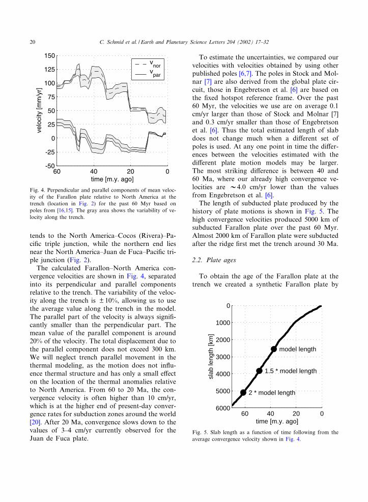
The calculated Farallon^North America con-vergence velocities are shown in Fig. 4, separatedinto its perpendicular and parallel componentsrelative to the trench. The variability of the veloc-ity along the trench is U 10%, allowing us to usethe average value along the trench in the model.The parallel part of the velocity is always signi¢-cantly smaller than the perpendicular part. Themean value of the parallel component is around20% of the velocity. The total displacement due tothe parallel component does not exceed 300 km.We will neglect trench parallel movement in thethermal modeling, as the motion does not in£u-ence thermal structure and has only a small e¡ecton the location of the thermal anomalies relativeto North America. From 60 to 20 Ma, the con-vergence velocity is often higher than 10 cm/yr,which is at the higher end of present-day conver-gence rates for subduction zones around the world[20]. After 20 Ma, convergence slows down to thevalues of 3^4 cm/yr currently observed for theJuan de Fuca plate.
To estimate the uncertainties, we compared ourvelocities with velocities obtained by using otherpublished poles [6,7]. The poles in Stock and Mol-nar [7] are also derived from the global plate cir-cuit, those in Engebretson et al. [6] are based onthe ¢xed hotspot reference frame. Over the past60 Myr, the velocities we use are on average 0.1cm/yr larger than those of Stock and Molnar [7]and 0.3 cm/yr smaller than those of Engebretsonet al. [6]. Thus the total estimated length of slabdoes not change much when a di¡erent set ofpoles is used. At any one point in time the di¡er-ences between the velocities estimated with thedi¡erent plate motion models may be larger.The most striking di¡erence is between 40 and60 Ma, where our already high convergence ve-locities are V4.0 cm/yr lower than the valuesfrom Engebretson et al. [6].
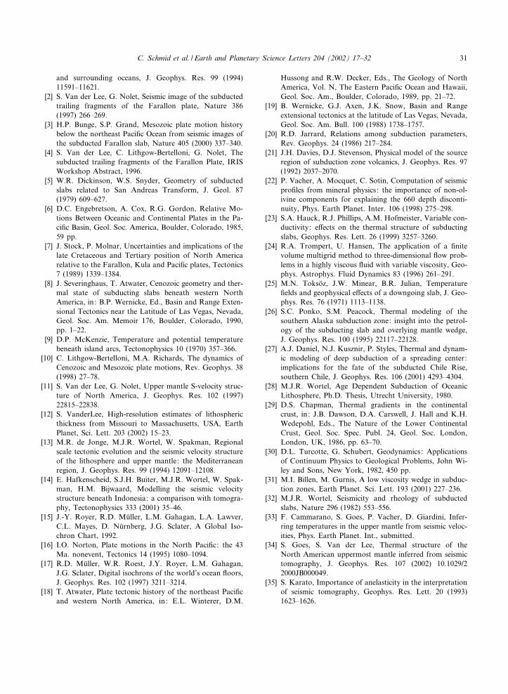
The length of subducted plate produced by thehistory of plate motions is shown in Fig. 5. Thehigh convergence velocities produced 5000 km ofsubducted Farallon plate over the past 60 Myr.Almost 2000 km of Farallon plate were subductedafter the ridge ¢rst met the trench around 30 Ma.
2.2. Plate ages
To obtain the age of the Farallon plate at thetrench we created a synthetic Farallon plate by
0204060
0
1000
2000
3000
4000
5000
6000
slab
leng
th [k
m]
time [m.y. ago]
model length
1.5 * model length
2 * model length
Fig. 5. Slab length as a function of time following from theaverage convergence velocity shown in Fig. 4.
Fig. 4. Perpendicular and parallel components of mean veloc-ity of the Farallon plate relative to North America at thetrench (location in Fig. 2) for the past 60 Myr based onpoles from [16,15]. The gray area shows the variability of ve-locity along the trench.
EPSL 6439 11-11-02 Cyaan Magenta Geel Zwart
C. Schmid et al. / Earth and Planetary Science Letters 204 (2002) 17^3220

rotating the Paci¢c isochrons [17] with ¢nite rota-tion poles of the Paci¢c^Farallon spreading [15].We then rotate the synthetic plate back to its pastposition relative to North America and read outthe age values along the trench.
Fig. 6 shows the age of the Farallon plate at thetrench for the past 60 Myr. The variability of thelithospheric age along the trench is much higherthan that of the velocities (Fig. 4) and is the causefor signi¢cant lateral variations in thermal struc-ture of the slab. The slab window that starts toevolve shortly after 30 Ma is clearly visible. Theuncertainties in the ages depend on the uncertain-
ties in the velocities and therefore we also com-pared age maps obtained with a di¡erent set ofpoles [7]. Di¡erences were within U 10 Myr, exceptnear transform faults, where the di¡erences can behigher due to di¡erences in transform location.
3. Kinematic thermal modeling
3.1. Temperatures
To determine the consequences of the knownplate motions for subduction-related thermal
Fig. 6. Age of the Farallon plate consumed at the trench during the past 60 Myr. Colors show the age of the lithosphere thatwas consumed at a particular point in time and position along trench (location in Fig. 2). For the white area in the upper leftno data are available. In the model an average value from neighboring points was used for this region. The white area in thebottom center corresponds to the slab window. The notable age discontinuities are due to transform faults.
EPSL 6439 11-11-02 Cyaan Magenta Geel Zwart
C. Schmid et al. / Earth and Planetary Science Letters 204 (2002) 17^32 21

anomalies in the mantle we solve the three-dimen-sional energy equation:
DTD t
¼ 9!WU 9!T3 v!W9
!T þ A
bMCpþ KgTvz
Cpð1Þ
Here T is temperature, t time, U thermal di¡usity,v velocity, A heat production, bM mantle density,Cp speci¢c heat, K thermal expansivity, g gravita-tional acceleration and vz the vertical velocitycomponent. Adiabatic heating (KgTvz/Cp) is in-cluded to obtain real rather than potential tem-peratures. We neglect viscous heating, which hasbeen shown to be small for the constant viscosity£ow ¢eld that we use [21]. The e¡ects of phasetransitions are also neglected, since latent heat ina pyrolite composition induces temperature jumpsno more than 50 K [22]. Variable thermal con-ductivity [23] was also tested, but the e¡ect wassmall for the plate dips and velocities we used.
Eq. 1 is solved numerically on a Cartesian gridin three-dimension. Following Trompert andHansen [24], we use a ¢nite volume discretizationin space, together with a Crank^Nicholsonscheme and second-order upwind in time and amultigrid solver with damped Jacobi as a smooth-er. The model was compared with published ther-mo-kinematic models [21,23,25^27].
The calculations start with an adiabatic mantlewith a potential temperature of 1300‡C, to whichwe add a subducting plate with the thermalstructure of 60 Myr old oceanic lithosphere anda continental overriding plate. Temperatures inthe oceanic lithosphere as a function of age arecalculated using the boundary layer model with aconstant basal heat £ux [28].
The origin of our box is located at the surfaceat point AP shown in Fig. 2. We used a grid di-mension of 512U64U128 points corresponding to5440 km in x-direction (perpendicular to thetrench) by 2560 km in y-direction (along thetrench) by 1000 km in z-direction (vertical).Grid spacing ranges from 5.5 to 12 km in x-direc-tion and 5 to 7 km in z-direction. In y-direction itis possible to use a constant large spacing of 40km since there are only conductive £uxes in thisdirection (trench parallel motion being neglected).
At the top boundary (z=0) temperature is kept
at 0‡C, except at the ridge where temperature isset to the potential mantle temperature T=Tm =1300‡C. At the bottom a temperature gradient of0.5W1033‡C m31 is imposed, consistent with anadiabatic temperature gradient. We assume DT/Dy=0‡C/m at the box boundaries y=0 and y=2560 km. At the boundary at x=5040 km temper-ature is ¢xed to a continental geotherm with asurface heat £ow of 60 m Wm2 [29] for the 90km thick lithosphere and a 1300‡C adiabat forthe mantle. On the boundary at x=3400 kmwe prescribe temperatures of the incoming ocean-ic lithosphere consistent with the evolution of plateage along the trench through time (Fig. 6) and a1300‡C adiabat. In the overriding plate, heat pro-duction consistent with the continental geothermis included [29]. In Table 1, the values of the geo-thermal parameters that were used are listed.
The subduction geometry through time, i.e. thepath of the slab through the mantle, is controlledby slab^mantle dynamics, which are not wellunderstood. Geological data and seismic tomog-raphy provide some constraints on the evolutionof slab geometry. For example, the leading edgeof the slab window is residing in the upper mantle[2]. The horizontal extent of the slab window for a0‡ slab dip is shown in Fig. 1. Any model slabdips steeper than about 20‡ would put the leadingedge of the slab window into the lower mantle.For the thermal modeling we chose to use a con-stant dip of 15‡, which connects the trench loca-tion with the present-day entry point of the slabinto the lower mantle as ¢xed by Grand’s model[1] (Grand, personal communication, 2001) (Fig.3). The thermal anomalies of the subducted ma-terial are controlled by the time since subductionand by the age upon subduction and not by the
Table 1Thermal modeling parameters
Name Value Unit
Thermal di¡usity (U) 1036 m2s31
Mantle density (bM) 3300 kg m33
Speci¢c heat (cp) 1050 J kg31‡C31
Thermal expansion coe⁄cient (K) 3.3W1035 ‡C31
Potential mantle temperature 1300 ‡CBasal adiabatic heat£ux 2.5W1032 W m32
Mantle heat£ux at base of plate 9.3W1033 W m32
Heat production (A) 2.0W1036 W m33
EPSL 6439 11-11-02 Cyaan Magenta Geel Zwart
C. Schmid et al. / Earth and Planetary Science Letters 204 (2002) 17^3222

exact trajectory followed by the subducted mate-rial. Thus, even though our model geometry maynot correspond to the geometrical slab evolution,the anomalies as a function of time since subduc-tion are constrained by our modeling. The possi-ble evolution of the slab geometry is discussed inSection 5, based on geological constraints anddiscrepancies between the geometry of the thermalmodel and the tomography. For a rigid continu-ous slab with a constant 15‡ dip, the material nowat a depth of 660 km in the model subducted at 37Ma. The model is started 60 Ma in order to avoidany in£uences on the present-day thermal struc-ture from the initial model.
3.2. Velocity ¢eld
The velocity ¢eld is input and must satisfy thecontinuity equation
9!W v!¼ 0: ð2Þ
Due to the use of the ¢nite volume technique,satisfying Eq. 2 for each grid cell is importantto avoid instabilities in the solution.
The input velocity ¢eld is illustrated in Fig. 7,superimposed on the temperature solution for across section at yV1250 km, approximatelythrough the center of the slab window (Fig. 6).The overriding continental lithosphere is kept¢xed down to 90 km depth. The subducting plateis entered from the left side of the model(x=3400 km) according to the trench-perpendic-ular velocities from Fig. 4. Variations in averagevelocity through time are incorporated, and resultin the decrease of velocities with time seen in Fig.7. For the mantle above and below the slab weuse a two-dimensional analytical solution for cor-ner £ow in a constant viscosity mantle ([30],p. 250^251). This velocity ¢eld, corresponding toactive subduction, is shown in the panels for 40and 30 Ma (Fig. 7). After subduction of theyoungest edge of the plate we assume no moresurface plate convergence in the slab window andno £ow in the mantle at depths less than the top ofthe sinking slab. The rest of the slab moves withthe same velocity as the still actively subductingpart of the plate, so that the integrity of the slab
along strike is maintained. Mantle £ow is againcalculated analytically. This velocity ¢eld for thesinking part of the slab is shown in the cross sec-tions for 20 Ma, 10 Ma and the present day.
The assumption of no £ow above the sinkingslab provides a ¢rst-order model for the thermalstructure within the slab window. If mantle £owwere dragged into the window by the sinking slab,cool isotherms would be drawn down behind thesinking slab leading to cooler temperatures in theslab window than the model shown. If mantle£ow ¢lled the slab window with warmer material,temperatures within the window might be warmerthan modeled now. Flow in the mantle wedgeabove the slab may be more complex than theconstant viscosity solution used here. This canhave signi¢cant e¡ects on the thermal structureof the mantle wedge (e.g. [31]), but is expectedto have only a minor in£uence on the tempera-tures of the slab itself.
4. Thermal modeling results
4.1. Thermal structure of the Farallon slab
The evolution of the thermal structure throughtime (Fig. 7) shows that the thermal anomaly as-sociated with subduction decreased signi¢cantlyas the subducted material became younger inage and active subduction ceased. At 40 Ma,upper mantle slab anomalies exceed 600‡C, whileat 0 Ma the anomalies are only 200^300‡C. Fur-thermore, while initially the thermal anomaly de-creased with depth, at the ¢nal stages the e¡ectsof the slab window and decreasing lithosphericage dominate and anomalies are smallest above400 km and increase in the transition zone.
Fig. 8a shows the present-day thermal struc-ture, in a dip-parallel slice, roughly through thecore of the low-temperature anomaly. Only uppermantle thermal anomalies below 100 km (i.e. be-low the continental lithosphere) are shown. All ofthe subducted plate still has a thermal anomaly inthe range of 200^400‡C. Thus the subducted ma-terial is not thermally equilibrated and these ther-mal anomalies are still su⁄cient to introduce asigni¢cant viscosity and seismic velocity contrast
EPSL 6439 11-11-02 Cyaan Magenta Geel Zwart
C. Schmid et al. / Earth and Planetary Science Letters 204 (2002) 17^32 23

with the surrounding mantle. The actively sub-ducting parts of the slab have larger thermalanomalies of 500^600‡C, but only down to about200 km depth. Within the slab window, temper-
atures are 100 to 200‡C cooler than the surround-ing mantle. These temperatures may be somewhatunderestimated or overestimated due to the as-sumed absence of £ow into the slab window.
40 m.y. ago
30 m.y. ago
20 m.y. ago
10 m.y. ago
0 500 1000 1500 2000 2500 3000
0
200
400
600
distance perpendicular to the trench (km)
dept
h (k
m)
0 m.y. ago
1600
14001200
Fig. 7. Two-dimensional cross sections at di¡erent times of the model run, perpendicular to the trench at position y=1250 kmfrom point AP (Figs. 2 and 6), close to the middle of the slab window. The trench is located at x=0 km. Only the upper mantlepart of the model is shown. The cross section at 0 Ma corresponds to the present day. Black arrows illustrate the velocity ¢eldevery tenth grid point and are scaled according to velocity size, with the largest arrow corresponding to the maximum velocities40 Ma, i.e. 12 cm/yr (Fig. 4). Temperature contours are drawn every 200‡C.
EPSL 6439 11-11-02 Cyaan Magenta Geel Zwart
C. Schmid et al. / Earth and Planetary Science Letters 204 (2002) 17^3224

The analytical model used by Severinghaus andAtwater [8] keeps the temperatures at the slabboundaries ¢xed thus not allowing the slab tocool o¡ the surrounding mantle. Slab tempera-tures from this model therefore represent anupper estimate. Nevertheless the results from Se-veringhaus and Atwater [8] are not inconsistentwith our thermal slab structure. They de¢ned as-similation of the slab based on the cessation ofseismicity, assuming that the presence of seismic-ity is related to a signi¢cant temperature-con-trolled rheological di¡erence between the slaband the surrounding mantle. The seismicity cut-
o¡ corresponds to a thermal anomaly of about600‡C [32]. Indeed most of the subducted litho-sphere is warmer than this. But the thermalanomalies are large enough for this lithosphereto be coherent and to be detectable by seismictomography.
4.2. Synthetic seismic velocity structure
To compare the thermal anomalies of our mod-el with the S-wave velocity anomalies from to-mography, we convert the modeled temperaturesto S-wave velocities. We use an update [33] of the
Fig. 8. Present-day thermal structure of the slab resulting from the model. Shown is a slice along the top of the slab, lookingdown-dip at the slab-mantle interface. Only the depth range from 100 km to 660 km is shown. (a) Temperature di¡erence relativeto the right side of the model. (b) Resulting shear wave velocity anomaly in %.
EPSL 6439 11-11-02 Cyaan Magenta Geel Zwart
C. Schmid et al. / Earth and Planetary Science Letters 204 (2002) 17^32 25

method and data used by Vacher et al. [22]. Theconversion assumes a pyrolitic composition forthe whole upper mantle. A harzburgitic litho-sphere is slightly faster than pyrolite ; on the otherhand, oceanic crust has lower velocities than py-rolite in the transition zone [33]. Overall, the e¡ectof composition is secondary to the e¡ect of tem-perature [33,34]. The phase transitions in olivineand garnet/pyroxene components are ¢xed to takeplace at 400, 520 and 660 km depth. The e¡ect ofanelasticity was included following Karato [35],with a frequency dependence a=0.15, qualityscaling factor Q0 = 0.5 and parametrization ofthe activation energy in terms of melting temper-ature with a scaling factor g=30. This results inan anelasticity pro¢le similar to the QS(z) ofPREM [36] for a 1300‡C mantle adiabat. A di¡er-ent set of anelasticity parameters does not signi¢-cantly a¡ect our conclusions as long as the pro¢lefor the mantle adiabat is close to the QS ofPREM and other one-dimensional Earth models.S-wave velocity anomalies are calculated relativeto the velocities along a 1300‡C mantle adiabat.This choice of a reference model is motivated bythe agreement between synthetic seismic velocitiesfor a V1300‡C mantle adiabat and one-dimen-sional seismic reference models [37]. Furthermore,positive velocity anomalies dominate in tomo-graphic models of the North American transitionzone, consistent with a subduction-related origin.
Fig. 8b shows the resulting S-velocity anomaliesfor the same slice as shown in Fig. 8a. All of thethermal anomalies related to the subducted Far-allon plate result in signi¢cant VS anomalies ofV2% or more. The velocity signature is not sim-ply the thermal signature multiplied by a constantscaling factor. Due to a decreasing sensitivity ofvelocity to temperature with depth, velocityanomalies decrease with depth more strongly thanthe thermal anomaly in the actively subductingparts of the plate and velocity anomalies hardlyincrease with depth below the slab window.
5. Comparison with seismic tomography
We compare the amplitude and the location ofthe velocity anomalies obtained from the thermal
kinematic model with the tomographic anomaliesin the upper mantle as imaged in model NA00[12,34]. Since the geometry of the tomographicanomalies (Figs. 2 and 3) and the thermal model(Figs. 7 and 8) are di¡erent, a slice by slice com-parison is not possible. However, a comparison ofthe total volume of the positive, i.e. subduction-related, velocity anomaly imaged in the uppermantle allows us to constrain which part of thesubducted Farallon plate is actually imaged bythe upper mantle tomography. This result, togeth-er with a comparison of the anomaly locations,provides constraints on the evolution of slab ge-ometry in the transition zone.
5.1. Amplitude of the anomalies
To obtain constraints on the total amount ofsubducted material present in the upper mantle,positive seismic velocity anomalies are integratedover the length and width of the thermal model,and the corresponding region between 25‡N and50‡N in NA00. All mantle heterogeneity not as-sociated with the subducted Farallon plate, e.g.structure due to the North American lithosphere,is excluded by limiting the depth range of integra-tion to below 350 km for NA00, and below 225km in the thermal model. The depth ranges re£ectthe di¡erence in slab geometry in the tomographicand the thermal model.
To assess how much of the di¡erence betweenmodel and tomographic anomalies is due to lim-ited resolving power in the tomographic imaging,we performed a resolution test. For this test themodeled velocity anomalies were projected ontogeographical coordinates and synthetic seismicdata were computed using the same data coverageas used to derive model NA00. These syntheticdata were then subjected to the same tomographicinversion procedure as NA00. The resolution testshows that, despite the e¡ects of damping andsmoothing, the temperature anomalies of the ki-nematic model are detectable by the seismic dataused to derive NA00.
The ratio of the integrated velocity anomalyfrom NA00 and the anomaly derived from thethermal model is 1.2 (Fig. 9a). The volume inte-gral of the resolved subduction-related positive
EPSL 6439 11-11-02 Cyaan Magenta Geel Zwart
C. Schmid et al. / Earth and Planetary Science Letters 204 (2002) 17^3226

velocity anomalies is 1.6 times lower than in theinput from the thermal model. If this is taken as ameasure for the limited resolution the integratedanomaly in NA00 exceeds the model anomaly bya factor 1.9.
Peak anomalies in the velocities derived fromthe thermal model are about 1.5 times higherthan in NA00, but NA00 has a larger amountof low amplitude anomalies (Fig. 9b). Further-more, in NA00 a steady linear decrease from alarge number of low amplitude anomalies to asmall number of strong anomalies is observed.In the thermal model this decrease is not linear;the number of points with anomalies in the rangefrom 50 ms31 to 100 ms31 is constant. Due todamping and smoothing applied in the tomo-graphic inversion, peak anomalies in the resolvedoutput model are 2.6 times lower than in the in-put from the thermal model. The distribution ofthe amplitudes of the velocity anomalies after theresolution test, a steady decrease, resembles NA00more than the input model.
The amplitude of the integrated thermal anom-aly depends predominantly on the length of sub-ducted Farallon slab in the upper mantle, and ishardly in£uenced by the position of the slab ma-terial within the mantle. The conversion to seismic
velocities, however, varies with depth, whichmakes the amplitude of the integrated syntheticvelocity anomaly dependent on the depth at whichthe subducted material is located. The thermalmodel anomaly is present throughout the depthof the upper mantle, while the imaged anomaliesin NA00 that are interpreted as slab remnants areconcentrated in the transition zone (Fig. 9a). Thusthe total velocity anomaly estimated from ourthermal model is likely an overestimate, sincebringing the thermal anomalies to larger depthswould decrease the associated velocity anomalies.Taking this into account, the integrated anomalyin NA00 exceeds the model anomaly by an evenlarger amount. If we restrict the depth range to be350 to 650 km in the thermal model and the out-put model of the resolution test, we obtain a ratioof about 2.5 between NA00 and the resolvedmodel anomalies.
The resolution correction of 1.6 is only an esti-mate. The damping and smoothing done in tomo-graphic inversions generally leads to an underes-timate of total anomaly amplitudes. But, forexample, ignoring the in£uence of mode couplingmay lead to an overestimate of high velocitiesbelow a low velocity region such as the westernUS [38]. Also, a £at lying slab (as seen in NA00)
300 400 500 6000
2
4
6
8x 10
6
inte
grat
ed a
nom
aly
[km
4 /s]
depth [km]0 50 100 150
0
5
10
15
20
num
. of p
ts/1
000
NA00
0 50 100 150 0
5
10
15
20
dvs [m/s]
Input
0 50 100 150 0
5
10
15
20Resolutiona) b)
Fig. 9. Comparison of integrated positive anomalies in the tomographic model NA00 with the velocities derived from the thermalmodel before and after a tomographic resolution test. Depth range is 350^650 km for NA00, 225^650 km for the thermal modeland the resolution test. Only points located between 25‡N to 50‡N were considered in NA00, in all three cases only anomaliesbigger than 10 m/s where considered. All data points are on the same grid, so that it was possible to simply sum up the anoma-lies. (a) Integrated velocity anomalies per 25 km thick depth layer as a function of depth. Integrated anomaly (km4/s) over thewhole depth range is 6.83W107 for NA00, 5.89W107 for the thermal model and 3.58W107 for the resolution test. We recover onlyabout half of the integrated input anomaly in the tomographic inversion. (b) Histogram showing the distribution of positiveanomalies as a function of amplitude (m/s). Note the shift from a small number of strong anomalies to a large number of smallanomalies between input and resolution.
EPSL 6439 11-11-02 Cyaan Magenta Geel Zwart
C. Schmid et al. / Earth and Planetary Science Letters 204 (2002) 17^32 27

is better resolvable than a dipping slab. Resolu-tion further varies laterally and the location of theanomalies in NA00 is not exactly the same as inthe thermal model used as input for the resolutiontest. Given all these uncertainties, the thermalmodel predicts an upper mantle seismic velocityanomaly that is about 1.5 to 2.0 times smallerthan what is imaged by seismic tomography.
In order to produce the larger anomaly imagedin NA00 more cold material is needed in theupper mantle, material that subducted earlierthan 37 Myr ago. Assuming that imaged slab vol-ume scales with slab length, we can estimate fromFig. 5 a time since subduction between 50 and 60Myr for the oldest parts of the slab still residing inthe upper mantle. A maximum length, not thick-ened, continuous slab that connects the trenchand the top of the seismic anomaly in the lowermantle would correspond to 43 Myr of subductedmaterial, only slightly more than in the thermalmodel. Thus the amount of slab material in theupper mantle implied by the observed seismicanomalies (50 to 60 Myr of slab) requires signi¢-cant internal deformation of the slab in the tran-sition zone.
5.2. Location of the anomalies
Although we did not attempt to model slab ge-ometry, a comparison of our geometrically ¢rst-order model with the location of tomographic ve-locity anomalies provides some insight. In ourmodel the slab window reaches to a depth ofabout 400 km (Fig. 7). This is roughly consistentwith the tomographic images of Van der Lee andNolet [2,11], which show mainly low velocitiesunder the western United States down to 350km, indicating the absence of slab above thisdepth. Although the depths of the modeled slabmaterial are reasonable, most of the slab-relatedanomaly in the tomographic model is located westof that in our thermal model. This indicates thatwe use a horizontal subduction component rela-tive to North America that is too large on aver-age. The horizontal velocities in our thermal mod-el are determined by the subduction velocities,which follow from the plate motions assuming arigid, coherent plate. Since we ¢nd that all of the
slab should be seismically detectable, the western-most edge of the imaged high velocity materialmust coincide with the leading edge of the slabwindow. Horizontal velocities of this westernmostimaged material relative to North America musthave been about one-quarter of the convergencevelocity of the subducting parts of the Farallonplate north and south of the slab window. Thisdi¡erence in subduction velocity indicates that theslab was not moving as a rigid, coherent body.
The thermal structure of the subducted Faral-lon plate is controlled by the relative convergencebetween the Farallon and North American plates.However, the absolute movement of North Amer-ica relative to a hotspot reference frame in£u-enced the geometry of the subducting Farallonplate through time and thereby the location ofthe seismic anomalies. According to the poles giv-en in Mu«ller et al. [39], North America’s absolutemovement in the Cenozoic was about 2.5 to 3 cm/yr in a southwest direction and roughly oppositeto the Farallon absolute movement. The total dis-placement of North America relative to the hot-spots amounts to approximately 1700 km for thepast 60 Myr. However, only if accompanied byinternal plate deformation do the absolute mo-tions lead to a di¡erent relative velocity betweenthe subducted Farallon and North America thanbetween the surface Farallon plate and NorthAmerica.
5.3. Evolution of slab geometry
Fifty to sixty Ma was a special time in the geo-logic history of North America. From the mid-Jurassic until V80 Ma volcanism and mountainbuilding processes were concentrated along thecoast, indicating a normal slab dip [18]. After 80Ma, the volcanic belt shifted to the east by about1000 km over the period of several million years[18]. The hypothesis of a £attening subductingslab is the most likely explanation for the east-ward shift of magmatism [18]. This eastward shiftcoincides in time with the far inland occurringLaramide orogeny (70^50 Ma) [40]. It is reason-able to assume that the £at subduction and theLaramide orogeny are linked [41]. The magmaticrecord indicates that the episode of £at slab sub-
EPSL 6439 11-11-02 Cyaan Magenta Geel Zwart
C. Schmid et al. / Earth and Planetary Science Letters 204 (2002) 17^3228

duction ceased after V20 to 30 Myr, whenaround 40 Ma (depending on the latitude) thevolcanic belt shifts back to the west [18]. Thiswestward shift of magmatism is less sharply de-¢ned in time than the preceding eastward shift.Basin and Range extension in the middle andlate Cenozoic has been linked to the removal ofthe £at slab and the subsequent in£ux of warmmantle [18].
Several causes for slab £attening during theLaramide orogeny, have been proposed: (1) anincrease in the westward component of NorthAmerica’s absolute plate velocities [6,39] leadingto trench roll-back and lithospheric doubling [42],(2) increased buoyancy of the slab, for example,through the subduction of an oceanic plateauwith an anomalously thick crust [18]. Convectionmodeling [43] demonstrates that £at subductionon the scale inferred for North America at 70^50 Ma probably requires a combination of (1)and (2).
The same mechanisms may also a¡ect the tran-sition of the slab through the endothermic phasetransition and viscosity increase at 660 km depth.According to Christensen [44] an oceanwardtrench migration velocity of 2.5^3 cm/yr is justhigh enough to inhibit penetration into the lowermantle. The stalling of slab penetration in hismodels is the result of slab £attening at the baseof the transition zone. A £at slab geometry inher-ited from the phase of £at subduction would havea similar e¡ect. Slab buoyancy due to an anom-alously thick oceanic crust may also a¡ect thetransition into the lower mantle. The phase tran-sition to perovskite+magnesiowu«stite in oceaniccrust occurs at a depth larger than in the sur-rounding mantle. Therefore, oceanic crust, whichthroughout most of the upper mantle is denserthan the rest of the lithosphere, is relatively buoy-ant around 660 km depth [45]. If the oceanic crustis su⁄ciently thick, the crustal buoyancy may be-come a factor that hinders penetration into thelower mantle. We infer that penetration of theslab into the lower mantle stalled around 60Ma, which is later than the start of trench roll-back around 80 Ma. [16,18]. The roll-back byitself was seemingly not su⁄cient to stop thetransfer of slab material into the lower mantle.
The extra buoyancy and geometry of the £atslab may have been the factors that ultimatelyimpeded further penetration. The cartoon in Fig.10 summarizes the possible evolution of the sub-ducted Farallon plate. Signi¢cant internal defor-mation is necessary to accommodate the largeamount of slab material that subducted after pen-etration into the lower mantle was impeded. Con-tinued trench roll-back resulted in the accumula-tion of most of this material at the base of thetransition zone.
Internal deformation of the Farallon slab in thetransition zone would be facilitated by the rela-tively high slab temperatures (Figs. 7 and 8a). Thenon-uniform transition zone anomalies (Figs. 2and 3) may be an expression of slab bucklingand/or fragmentation. Such deformation mayproduce additional heat and fragmentation leadsto the formation of smaller segments that will be
40 m.y. ago
60 m.y. ago
80 m.y. ago
20 m.y. ago
0 m.y. ago
PAC FAR NAM
660 km
T V
Fig. 10. Cartoon of Farallon slab evolution in the uppermantle in a ¢xed hotspot reference frame. Abbreviations: T,trench; V, volcanoes. Only a small part of the lower mantleslab is shown. Consumption of the Farallon plate is the re-sult of absolute motion of both the Paci¢c^Farallon ridgeand the North American plate. After 80 Ma £at subductionis initiated and volcanism shifts far land inward. Around 40Ma the slab steepens again and volcanism migrates back to-wards the trench. The £atly subducted part of the slab ap-parently resisted penetration through the 660 km discontinu-ity and caused internal slab deformation in the transitionzone. In reality this deformation was a complex three-dimen-sional process.
EPSL 6439 11-11-02 Cyaan Magenta Geel Zwart
C. Schmid et al. / Earth and Planetary Science Letters 204 (2002) 17^32 29

warmed up faster and therefore the resultinganomaly would be smaller than modeled, requir-ing even more slab material to be accumulated inthe transition zone. On the other hand, slab thick-ening could slow the rate of conductive coolingcompared with cooling of an undeformed slab.
6. Conclusions
Lower mantle seismic velocity anomalies due tosubduction of the Farallon plate [1] (Grand, per-sonal communication, 2001) have been quantita-tively predicted from the long history of subduc-tion [3,10]. The thermal anomaly of the uppermantle Farallon slab, however, has qualitativelybeen predicted to be small based on the youngage, high subduction velocities and the formationof the slab window after the Farallon^Paci¢cridge collided with the Farallon^North Americatrench [8]. Nevertheless, high velocities havebeen imaged in the transition zone beneath NorthAmerica and interpreted as representing the sub-ducted trailing fragments of the Farallon plate [2].We have modeled the thermal signature of thesubducted Farallon plate in the upper mantlebased on the Cenozoic plate tectonic history toinvestigate to what extent the slab is thermallyequilibrated and which part of the subductedplate could correspond to the mapped seismicanomalies.
The following conclusions can be drawn:1. All of the subducted Farallon plate in the
upper mantle has a thermal anomaly of 200^400‡C. Thus, the plate is not thermally equili-brated with the surrounding mantle, althoughthe thermal anomalies are smaller than thosefor an actively subducting plate. The thermalsignature is su⁄cient to produce a detectableseismic velocity anomaly, and a signi¢cantrheological contrast with the mantle.
2. The proximity of some of the tomographicanomalies to the trench requires that part ofthe plate at depth did not move with the sameconvergence velocity as the plate fragments atthe surface. The subduction velocity of the slabat depth thus varied signi¢cantly along strikefor at least part of the past 60 Myr, possibly in
response to the development of the slab win-dow after ridge^trench collision started.
3. Analysis of the volumetrically integrated seis-mic velocity anomaly shows that 1.5 to 2.0times more material is imaged in the uppermantle seismic tomography than predicted bythe thermal model for a continuous unde-formed slab. In the kinematic thermal modelthe oldest material in the upper mantle sub-ducted V40 Myr ago. Assuming that volumescales with slab length, the tomographic modelrequires a time since subduction between 50^60Myr for the oldest parts of the slab residing inthe upper mantle. This indicates that the Far-allon plate is also internally deformed in thedown-dip direction. The deformation of theslab in the transition zone is probably causedby the same mechanisms that were responsiblefor £at subduction around 60 Ma. Firstly,anomalous slab buoyancy and geometry mayimpede slab penetration into the lower mantle.Secondly, the trenchward movement of theoverriding plate would have led to an accumu-lation of most of the subducted material at thebase of the transition zone, thus providing anadditional hindrance to slab penetration.The comparison of forward modeled thermal
structure based on plate motions with seismic ve-locity images provides a powerful tool to obtainconstraints on the evolution of a plate after sub-duction. Such constraints are important forunderstanding the role of slabs in mantle dynam-ics, and for the case of the Farallon plate provideinsight in the dynamics of the slab in the transi-tion zone.
Acknowledgements
We thank Steve Grand for making his velocitymodel available. We thank James Conder, RobVan der Voo and an anonymous reviewer fortheir constructive comments.[SK]
References
[1] S.P. Grand, Mantle shear structure beneath the Americas
EPSL 6439 11-11-02 Cyaan Magenta Geel Zwart
C. Schmid et al. / Earth and Planetary Science Letters 204 (2002) 17^3230
and surrounding oceans, J. Geophys. Res. 99 (1994)11591^11621.
[2] S. Van der Lee, G. Nolet, Seismic image of the subductedtrailing fragments of the Farallon plate, Nature 386(1997) 266^269.
[3] H.P. Bunge, S.P. Grand, Mesozoic plate motion historybelow the northeast Paci¢c Ocean from seismic images ofthe subducted Farallon slab, Nature 405 (2000) 337^340.
[4] S. Van der Lee, C. Lithgow-Bertelloni, G. Nolet, Thesubducted trailing fragments of the Farallon Plate, IRISWorkshop Abstract, 1996.
[5] W.R. Dickinson, W.S. Snyder, Geometry of subductedslabs related to San Andreas Transform, J. Geol. 87(1979) 609^627.
[6] D.C. Engebretson, A. Cox, R.G. Gordon, Relative Mo-tions Between Oceanic and Continental Plates in the Pa-ci¢c Basin, Geol. Soc. America, Boulder, Colorado, 1985,59 pp.
[7] J. Stock, P. Molnar, Uncertainties and implications of thelate Cretaceous and Tertiary position of North Americarelative to the Farallon, Kula and Paci¢c plates, Tectonics7 (1989) 1339^1384.
[8] J. Severinghaus, T. Atwater, Cenozoic geometry and ther-mal state of subducting slabs beneath western NorthAmerica, in: B.P. Wernicke, Ed., Basin and Range Exten-sional Tectonics near the Latitude of Las Vegas, Nevada,Geol. Soc. Am. Memoir 176, Boulder, Colorado, 1990,pp. 1^22.
[9] D.P. McKenzie, Temperature and potential temperaturebeneath island arcs, Tectonophysics 10 (1970) 357^366.
[10] C. Lithgow-Bertelloni, M.A. Richards, The dynamics ofCenozoic and Mesozoic plate motions, Rev. Geophys. 38(1998) 27^78.
[11] S. Van der Lee, G. Nolet, Upper mantle S-velocity struc-ture of North America, J. Geophys. Res. 102 (1997)22815^22838.
[12] S. VanderLee, High-resolution estimates of lithosphericthickness from Missouri to Massachusetts, USA, EarthPlanet, Sci. Lett. 203 (2002) 15^23.
[13] M.R. de Jonge, M.J.R. Wortel, W. Spakman, Regionalscale tectonic evolution and the seismic velocity structureof the lithosphere and upper mantle: the Mediterraneanregion, J. Geophys. Res. 99 (1994) 12091^12108.
[14] E. Hafkenscheid, S.J.H. Buiter, M.J.R. Wortel, W. Spak-man, H.M. Bijwaard, Modelling the seismic velocitystructure beneath Indonesia: a comparison with tomogra-phy, Tectonophysics 333 (2001) 35^46.
[15] J.-Y. Royer, R.D. Mu«ller, L.M. Gahagan, L.A. Lawver,C.L. Mayes, D. Nu«rnberg, J.G. Sclater, A Global Iso-chron Chart, 1992.
[16] I.O. Norton, Plate motions in the North Paci¢c: the 43Ma. nonevent, Tectonics 14 (1995) 1080^1094.
[17] R.D. Mu«ller, W.R. Roest, J.Y. Royer, L.M. Gahagan,J.G. Sclater, Digital isochrons of the world’s ocean £oors,J. Geophys. Res. 102 (1997) 3211^3214.
[18] T. Atwater, Plate tectonic history of the northeast Paci¢cand western North America, in: E.L. Winterer, D.M.
Hussong and R.W. Decker, Eds., The Geology of NorthAmerica, Vol. N, The Eastern Paci¢c Ocean and Hawaii,Geol. Soc. Am., Boulder, Colorado, 1989, pp. 21^72.
[19] B. Wernicke, G.J. Axen, J.K. Snow, Basin and Rangeextensional tectonics at the latitude of Las Vegas, Nevada,Geol. Soc. Am. Bull. 100 (1988) 1738^1757.
[20] R.D. Jarrard, Relations among subduction parameters,Rev. Geophys. 24 (1986) 217^284.
[21] J.H. Davies, D.J. Stevenson, Physical model of the sourceregion of subduction zone volcanics, J. Geophys. Res. 97(1992) 2037^2070.
[22] P. Vacher, A. Mocquet, C. Sotin, Computation of seismicpro¢les from mineral physics: the importance of non-ol-ivine components for explaining the 660 depth disconti-nuity, Phys. Earth Planet. Inter. 106 (1998) 275^298.
[23] S.A. Hauck, R.J. Phillips, A.M. Hofmeister, Variable con-ductivity: e¡ects on the thermal structure of subductingslabs, Geophys. Res. Lett. 26 (1999) 3257^3260.
[24] R.A. Trompert, U. Hansen, The application of a ¢nitevolume multigrid method to three-dimensional £ow prob-lems in a highly viscous £uid with variable viscosity, Geo-phys. Astrophys. Fluid Dynamics 83 (1996) 261^291.
[25] M.N. Tokso«z, J.W. Minear, B.R. Julian, Temperature¢elds and geophysical e¡ects of a downgoing slab, J. Geo-phys. Res. 76 (1971) 1113^1138.
[26] S.C. Ponko, S.M. Peacock, Thermal modeling of thesouthern Alaska subduction zone: insight into the petrol-ogy of the subducting slab and overlying mantle wedge,J. Geophys. Res. 100 (1995) 22117^22128.
[27] A.J. Daniel, N.J. Kusznir, P. Styles, Thermal and dynam-ic modeling of deep subduction of a spreading center:implications for the fate of the subducted Chile Rise,southern Chile, J. Geophys. Res. 106 (2001) 4293^4304.
[28] M.J.R. Wortel, Age Dependent Subduction of OceanicLithosphere, Ph.D. Thesis, Utrecht University, 1980.
[29] D.S. Chapman, Thermal gradients in the continentalcrust, in: J.B. Dawson, D.A. Carswell, J. Hall and K.H.Wedepohl, Eds., The Nature of the Lower ContinentalCrust, Geol. Soc. Spec. Publ. 24, Geol. Soc. London,London, UK, 1986, pp. 63^70.
[30] D.L. Turcotte, G. Schubert, Geodynamics: Applicationsof Continuum Physics to Geological Problems, John Wi-ley and Sons, New York, 1982, 450 pp.
[31] M.I. Billen, M. Gurnis, A low viscosity wedge in subduc-tion zones, Earth Planet. Sci. Lett. 193 (2001) 227^236.
[32] M.J.R. Wortel, Seismicity and rheology of subductedslabs, Nature 296 (1982) 553^556.
[33] F. Cammarano, S. Goes, P. Vacher, D. Giardini, Infer-ring temperatures in the upper mantle from seismic veloc-ities, Phys. Earth Planet. Int., submitted.
[34] S. Goes, S. Van der Lee, Thermal structure of theNorth American uppermost mantle inferred from seismictomography, J. Geophys. Res. 107 (2002) 10.1029/22000JB000049.
[35] S. Karato, Importance of anelasticity in the interpretationof seismic tomography, Geophys. Res. Lett. 20 (1993)1623^1626.
EPSL 6439 11-11-02 Cyaan Magenta Geel Zwart
C. Schmid et al. / Earth and Planetary Science Letters 204 (2002) 17^32 31

[36] A.M. Dziewonski, D.L. Anderson, Preliminary referenceEarth model, Phys. Earth Planet. Int. 25 (1981) 297^356.
[37] J.J. Ita, L. Stixrude, Petrology, elasticity, and compositionof the mantle transition zone, J. Geophys. Res. 97 (1992)6849^6866.
[38] H. Marquering, R. Snieder, G. Nolet, Waveform inver-sions and the signi¢cance of surface-wave mode coupling,Geophys. J. Int. 124 (1996) 258^278.
[39] R.D. Mu«ller, J.Y. Royer, L.A. Lawyer, Revised platemotions relative to the hotspots from combined Atlanticand Indian Ocean hotspot tracks, Geology 21 (1993) 275^278.
[40] W.P. Lipman, H.J. Protska, R.L. Christiansen, Evolvingsubduction zones in the Western United States as in-terpreted from igneous rocks, Science 174 (1971) 821^825.
[41] P. Bird, Formation of the Rocky Mountains, Western
United States: a continuum computer model, Nature239 (1988) 1501^1507.
[42] N.J. Vlaar, Thermal anomalies and magmatism due tolithospheric doubling and shifting, Earth Planet. Sci.Lett. 65 (1983) 322^330.
[43] J. Van Hunen, A.P. van den Berg, N.J. Vlaar, A thermo-mechanical model of horizontal subduction below anoverriding plate, Earth Planet. Sci. Lett. 182 (2000) 157^169.
[44] U.R. Christensen, The in£uence of trench migration onslab penetration into the lower mantle, Earth Planet. Sci.Lett. 140 (1996) 27^39.
[45] A.E. Ringwood, The role of the transition zone and 660km discontinuity in mantle dynamics, Phys. Earth Planet.Int. 86 (1994) 5^24.
[46] A.M. Dziewonski, A.L. Hales, E.R. Lapwood, Parametri-cally simple Earth models consistent with geophysicaldata, Phys. Earth Planet. Int. 10 (1975) 12^48.
EPSL 6439 11-11-02 Cyaan Magenta Geel Zwart
C. Schmid et al. / Earth and Planetary Science Letters 204 (2002) 17^3232