fastoop l module - swagelok · a swagelok pre-engineered subsystem fast loop module. 3 thewagelok s...
TRANSCRIPT

A Swagelok® Pre-Engineered
Subsystem
• Pre-engineeredsubsystems
availableinweeks,notmonths.
• Field-testeddesignensures
optimumsystemperformance.
• Designedforhandlinglongtransportlinesfromtaptoanalyzer
• Minimumpressuredropforfastestresponsetime
• Interlockinghandleshelppreventincorrectsequenceofoperation
FastLoopModuleApplicationGuide

SwagelokPre-EngineeredSubsystems
Swagelok now offers a series of
predesigned and preassembled
subsystems for use in all types of
plants and facilities where fluids are
being processed. Use Swagelok pre-
engineered subsystems to create fully
documented fluid sampling and control
systems and bring consistency to your
operations. Easy to install and operate,
these subsystems offer the high quality
and support you expect from Swagelok.
Contents
Why Use a Fast Loop Module? . . . . . . . . 3
Key Features . . . . . . . . . . . . . . . 4
Configurations . . . . . . . . . . . . . . 4
Options . . . . . . . . . . . . . . . . . . . 9
Where to Install a Fast Loop Module . . . . . . . . . 10
How to Select a Fast Loop Module . . . . . . . . . 11
Materials of Construction . . . . . . 12
Pressure-Temperature Ratings . . . . . . . . . . . . . . . . . 13
Testing . . . . . . . . . . . . . . . . . . . . 13
Cleaning and Packaging . . . . . . . 13
Flow Data . . . . . . . . . . . . . . . . . . 14
Dimensions . . . . . . . . . . . . . . . . . 17
Ordering Information . . . . . . . . . . 19
Regulatory Compliance . . . . . . . 20
A Swagelok Pre-Engineered Subsystem Fast Loop Module.
3
TheSwagelokFastLoopModule(FLM)Why Use a Fast Loop Module?Fastloopmodulesaredesignedtohandlehighflowsinsampletransportlinestoreducetime
delaysforonlineanalyzersystems.Locatedattheanalyzershelterandofferingabypass,the
Swagelokfastloopmodule(FLM)canisolatethesamplesystemandintroduceapurgegasfor
systemcleaning.TheFLMextractsasamplethroughafilterwhileusingthehighflowrateofthe
bypasstokeepthefilterelementclean.
Get a Faster Response
Thedistancebetweenasampletapandan
analyzercanmakeitdifficulttoobtainauseful
analyticalmeasurement.Sampletransportlines
arecommonlymorethan100 feet(30 meters)of
tubingorpipeandrequirehighpurgevolumes
toensureafreshsamplereachestheanalyzer.
Ideally,theflowfromthesampletaptothe
analyzersheltershouldtakeoneminuteorless.
Dependingonthetubingorpipesizeofthe
transportlines,aswellastheactualtransport
distance,thisflowratecouldbeashighas90stdft3/h(2548stdL/h).SeeFlow Data,
page 14,forguidelinesonsampletransportvolume.
Minimize Sample Waste
ASwagelokFLMalsominimizestheamountofextractedsamplethatissenttoflareordisposal.
AbypassfilterspeciallydesignedforfastloopsystemsenablestheFLMtoprovidehighflow
rates.Thefilterbypassesmuchofthesampleflowandreturnsittotheprocesslinethrougha
secondarytransportline.Togeneratehighflowratesthroughthisbypassloop,thereturnpoint
mustbeatalowerpressurethantheextractionpoint.
Tofurtherreducesamplewaste,manySwagelokFLMconfigurationsofferasamplereturnline
fromtheanalyzer(configurations2,3,and4).Thisoptioneliminatessendinganycontinuousflow
fromanonlineanalyzertoflareordisposal.
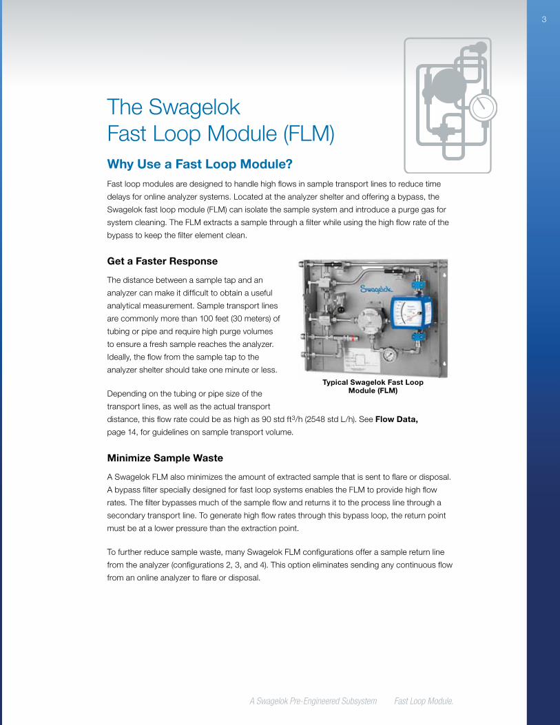
Typical Swagelok Fast Loop Module (FLM)
A Swagelok Pre-Engineered Subsystem Fast Loop Module
4
Key FeaturesDesignedtooptimizeonlineanalyzerperformance,Swagelokpre-engineeredsubsystemsare
fullytestedforcomponentperformance,systemintegrity,andfluidflowpriortoshipment.A
completepre-engineeredsubsystemcanbeconfiguredandorderedusingasingleordering
number,soorderanddeliveryissimpleandfast.AllSwagelokpre-engineeredsubsystems
arebackedbytheSwagelokLimitedLifetimeWarrantyandsupportedbySwageloksalesand
servicerepresentatives.
Interlocking Handles
TheSwagelokFLMincludestwoballvalvesthatswitchflowtoabypasstoisolatethesample
systemandanalyzerduringmaintenance.Thesebypassvalvesmaintainflowthroughthefast
looptokeepthesamplefreshatthebypasspoint.Aninnovativeinterlockinghandlesystem
allowsforsimultaneousactuationofthevalves,whileallowingforpackingadjustmentswithin
anindividualvalvebody.Insomeconfigurations,thedrainandpurgevalvesarelockedintothe
bypassvalvestoeliminatethepossibilityofopeningthedrainorpurgelineswhilethesystemis
insamplemode.Allhandlescanbelockedintopositiontoeliminatethepossibilityofaccidental
actuation.
Easy Maintenance
Designedtoenableeasyaccesstoanycomponentwithoutdisturbingothercomponentsinthe
system,theSwagelokFLMusesweldedassembliestoreducepotentialleakpointsandzero-
clearancefittingsinstraightruntubingsections.
Virtually Eliminates Water Hammer
Closingavalveinahigh-flowliquidlinecausesextremepressurespikes,referredtoaswater
hammer,whichcandamagesystemcomponents.TheSwagelokFLMeliminatesthepossibility
ofwaterhammerbymakingfullshutoffimpossible.Thebypassvalvesactuatesimultaneously
toeliminatethepossibilityofactuatingonlyoneofthevalves.Thethree-wayvalvedesignallows
flowtoswitchgraduallyfromsamplemodetobypassmode,insteadoftemporarilyshuttingoff
duringactuation.
Configurations TheFLMbaseconfigurationistheframeworkforallFLMsubsystems.TheotherFLM
configurationsofferadditionalfeaturestoaddressspecificsystemrequirements.
A Swagelok Pre-Engineered Subsystem Fast Loop Module.
5
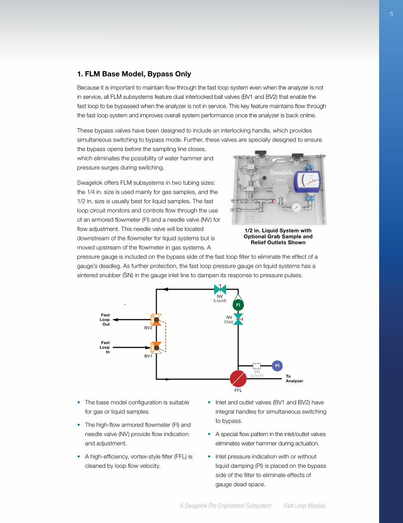
• Thebasemodelconfigurationissuitable
forgasorliquidsamples.
• Thehigh-flowarmoredflowmeter(Fl)and
needlevalve(NV)provideflowindication
andadjustment.
• Ahigh-efficiency,vortex-stylefilter(FFL)is
cleanedbyloopflowvelocity.
• Inletandoutletvalves(BV1andBV2)have
integralhandlesforsimultaneousswitching
tobypass.
• Aspecialflowpatternintheinlet/outletvalves
eliminateswaterhammerduringactuation.
• Inletpressureindicationwithorwithout
liquiddamping(PI)isplacedonthebypass
sideofthefiltertoeliminateeffectsof
gaugedeadspace.
1. FLM Base Model, Bypass Only
Becauseitisimportanttomaintainflowthroughthefastloopsystemevenwhentheanalyzerisnot
inservice,allFLMsubsystemsfeaturedualinterlockedballvalves(BV1andBV2)thatenablethe
fastlooptobebypassedwhentheanalyzerisnotinservice.Thiskeyfeaturemaintainsflowthrough
thefastloopsystemandimprovesoverallsystemperformanceoncetheanalyzerisbackonline.
Thesebypassvalveshavebeendesignedtoincludeaninterlockinghandle,whichprovides
simultaneousswitchingtobypassmode.Further,thesevalvesarespeciallydesignedtoensure
thebypassopensbeforethesamplinglinecloses,
whicheliminatesthepossibilityofwaterhammerand
pressuresurgesduringswitching.
SwagelokoffersFLMsubsystemsintwotubingsizes:
the1/4 in.sizeisusedmainlyforgassamples,andthe
1/2in.sizeisusuallybestforliquidsamples.Thefast
loopcircuitmonitorsandcontrolsflowthroughtheuse
ofanarmoredflowmeter(FI)andaneedlevalve(NV)for
flowadjustment.Thisneedlevalvewillbelocated
downstreamoftheflowmeterforliquidsystemsbutis
movedupstreamoftheflowmeteringassystems.A
pressuregaugeisincludedonthebypasssideofthefastloopfiltertoeliminatetheeffectofa
gauge’sdeadleg.Asfurtherprotection,thefastlooppressuregaugeonliquidsystemshasa
sinteredsnubber(SN)inthegaugeinletlinetodampenitsresponsetopressurepulses.
PI
BV2
BV1
NV
NV
FFL
SN
FI
C
C
Fast Loop
Out
Fast Loop
In
To Analyzer
(Liquid)
(Liquid)
(Gas)
1/2 in. Liquid System with Optional Grab Sample and
Relief Outlets Shown
A Swagelok Pre-Engineered Subsystem Fast Loop Module
6
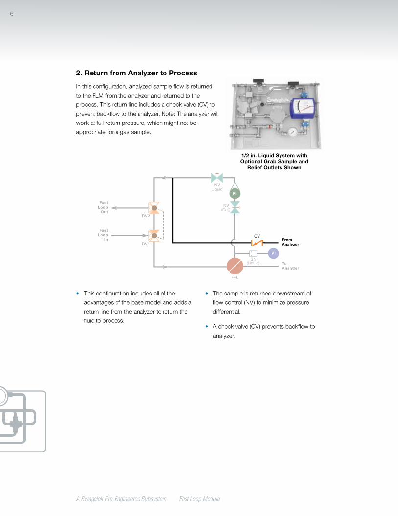
2. Return from Analyzer to Process
Inthisconfiguration,analyzedsampleflowisreturned
totheFLMfromtheanalyzerandreturnedtothe
process.Thisreturnlineincludesacheckvalve(CV)to
preventbackflowtotheanalyzer.Note:Theanalyzerwill
workatfullreturnpressure,whichmightnotbe
appropriateforagassample.
CV
PI
BV2
BV1
NV
NV
FFL
SN
C
C
FI
Fast Loop
Out
Fast Loop
In
To Analyzer
From Analyzer
(Liquid)
(Liquid)
(Gas)
• Thisconfigurationincludesallofthe
advantagesofthebasemodelandaddsa
returnlinefromtheanalyzertoreturnthe
fluidtoprocess.
• Thesampleisreturneddownstreamof
flowcontrol(NV)tominimizepressure
differential.
• Acheckvalve(CV)preventsbackflowto
analyzer.
1/2 in. Liquid System with Optional Grab Sample and
Relief Outlets Shown
A Swagelok Pre-Engineered Subsystem Fast Loop Module.
7
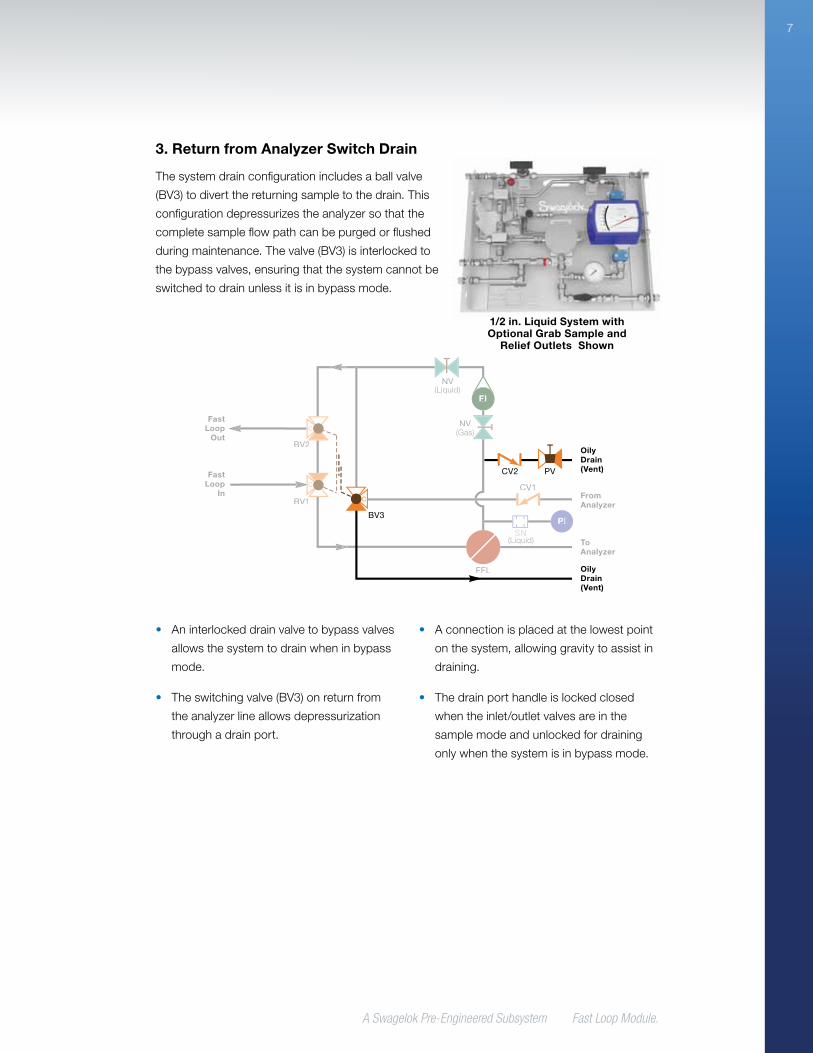
3. Return from Analyzer Switch Drain
Thesystemdrainconfigurationincludesaballvalve
(BV3)todivertthereturningsampletothedrain.This
configurationdepressurizestheanalyzersothatthe
completesampleflowpathcanbepurgedorflushed
duringmaintenance.Thevalve(BV3)isinterlockedto
thebypassvalves,ensuringthatthesystemcannotbe
switchedtodrainunlessitisinbypassmode.
BV3
CV2 PV
PI
BV2
BV1
CV1
NV
NV
FFL
SN
C
FI
C
C
Fast Loop
Out
Fast Loop
In
To Analyzer
Oily Drain (Vent)
Oily Drain (Vent)
From Analyzer
(Liquid)
(Liquid)
(Gas)
• Aninterlockeddrainvalvetobypassvalves
allowsthesystemtodrainwheninbypass
mode.
• Theswitchingvalve(BV3)onreturnfrom
theanalyzerlineallowsdepressurization
throughadrainport.
• Aconnectionisplacedatthelowestpoint
onthesystem,allowinggravitytoassistin
draining.
• Thedrainporthandleislockedclosed
whentheinlet/outletvalvesareinthe
samplemodeandunlockedfordraining
onlywhenthesystemisinbypassmode.
1/2 in. Liquid System with Optional Grab Sample and
Relief Outlets Shown

A Swagelok Pre-Engineered Subsystem Fast Loop Module
8
4. Gas or Liquid Purge, Manual Drain
Thisconfigurationusesaninertgasorsolventto
purgetheprocessfluidfromtheflowmeter(FI)and
filter(FFL)housingandisusefulwhenafilterelement
needstobechangedorcleaned.
Whenusedinconjunctionwiththereturnfrom
analyzerlineconfiguration,thepurgeconfiguration
allowsuserstoflushtheremainderoftheanalytical
samplesystemdownstreamoftheFLM.Thepurge
valve(BV4)ismechanicallylinkedtothedrainvalve
(BV3)sothatbothvalvescanbeactuated
simultaneously.Itisalsointerlockedwiththebypassvalves(BV1andBV2)toeliminateany
chanceofactuatingthepurgeanddrainvalvesunlessthesetwovalvesareswitchedtobypass
mode.Downstreamofthefilteranadditionalconnectiontodrainisincludedtoensurefull
systempurging.Thisdrainlineincludesamanualvalve(PV)andcheckvalve(CV2)toprevent
backflowfromthedrainorvent.
CV3NV2
BV4
PI
BV2
BV1
BV3
CV1
CV2 PV
NV1
NV1
FFL
SN
FI
C
C
C
Fast Loop
Out
Fast Loop
In
To Analyzer
Oily Drain (Vent)
Purge
Oily Drain (Vent)
From Analyzer
(Liquid)
(Liquid)
(Gas)
• Thisconfigurationallowsforpurgeinlet
throughanadditionalinterlockedvalve
thatcanonlybeactuatedwheninbypass
mode.
• Apurgeconnectionallowsapositive
pressurepurgefluidtoflushtheentire
systemtothedrain,formosteffective
systemdrainage.
• Thepurgevalve(BV4)isconnectedtothe
drainvalve(BV3)toensuresimultaneous
action.
1/2 in. Liquid System with Optional Grab Sample and
Relief Outlets Shown
A Swagelok Pre-Engineered Subsystem Fast Loop Module.
9
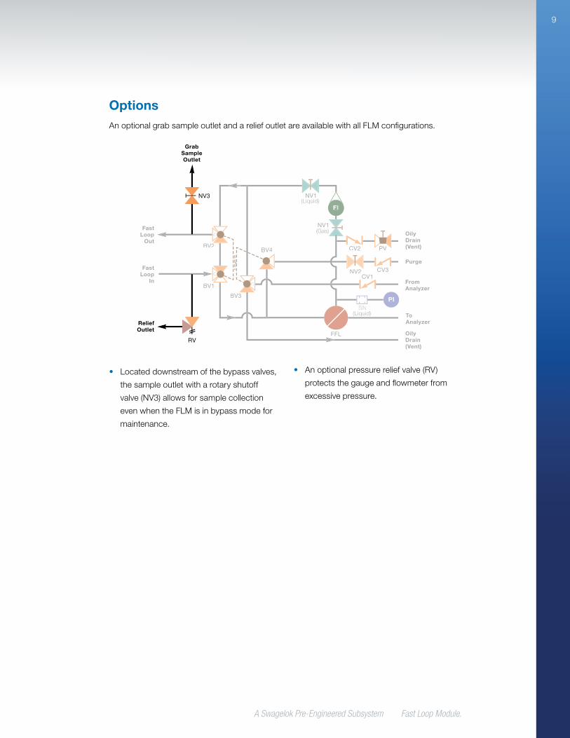
OptionsAnoptionalgrabsampleoutletandareliefoutletareavailablewithallFLMconfigurations.
RV
NV3
PI
BV2
BV1
BV3
BV4
CV1CV3
CV2 PV
NV1
NV1
FFL
SN
NV2
FI
C
C
C
Grab Sample Outlet
Fast Loop
Out
Fast Loop
In
Relief Outlet
(Liquid)
(Liquid)
(Gas)
To Analyzer
Oily Drain (Vent)
Purge
Oily Drain (Vent)
From Analyzer
• Locateddownstreamofthebypassvalves,
thesampleoutletwitharotaryshutoff
valve(NV3)allowsforsamplecollection
evenwhentheFLMisinbypassmodefor
maintenance.
• Anoptionalpressurereliefvalve(RV)
protectsthegaugeandflowmeterfrom
excessivepressure.
A Swagelok Pre-Engineered Subsystem Fast Loop Module
10
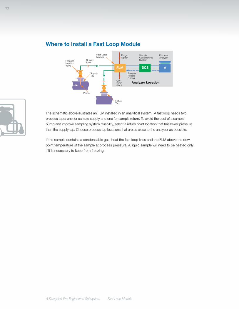
Where to Install a Fast Loop Module
TheschematicaboveillustratesanFLMinstalledinananalyticalsystem.Afastloopneedstwo
processtaps:oneforsamplesupplyandoneforsamplereturn.Toavoidthecostofasample
pumpandimprovesamplingsystemreliability,selectareturnpointlocationthathaslowerpressure
thanthesupplytap.Chooseprocesstaplocationsthatareasclosetotheanalyzeraspossible.
Ifthesamplecontainsacondensablegas,heatthefastlooplinesandtheFLMabovethedew
pointtemperatureofthesampleatprocesspressure.Aliquidsamplewillneedtobeheatedonly
ifitisnecessarytokeepfromfreezing.
ASCSFLM
Analyzer Location
PurgeOption
FastLoopModule
ProcessIsolationValve
SupplyLine
SupplyTap
Probe
ReturnTap
OilyDrain(Vent)
ProcessAnalyzer
SampleConditioningSystem
SampleReturnOption

A Swagelok Pre-Engineered Subsystem Fast Loop Module.
11
How to Select a Fast Loop Module
Tubing Size
SwagelokofferstheFLMintwotubingsizes.The1/2in.system,whichuses1/2in.tubingand
fittings,offerslessflowresistance(higherCv)and,therefore,ismoresuitableforliquidsamples.
The1/4in.versionisintendedmainlyforgases.
End Connections
Allsystemsincludea1/8in.(3mm)connectiontotheanalyzerlineanda1/4in.(6mm)
connectiontothepurgedrain.Half-inchsystemsinclude1/2in.(12mm)fastloopanddrain
connections.Quarter-inchsystemsinclude1/4in.(6mm)fastloopanddrainconnections.
Pressure Gauge
Thepressuregaugeisavailablewith63or100mm(21/2or4in.)dial,controlrangesfrom0to
150 bar(0to2175psi),andwithorwithoutdamping.
Flowmeter
Thestandardflowmetersforliquidsamplesarecalibratedforwaterflow.Thestandard
flowmetersforgassamplesarecalibratedforairat20°Cand1bar(absolute).
Filter Element
Chooseafiltersizebasedonthefiltrationneededfromtheelement.Poresizesfrom2to50μm
areavailable.
Formoreinformationaboutinstallation,operation,andmaintenanceofSwagelokFLM
subsystems,seetheFast Loop Module User’s Manual, MS-13-219.
A Swagelok Pre-Engineered Subsystem Fast Loop Module
12
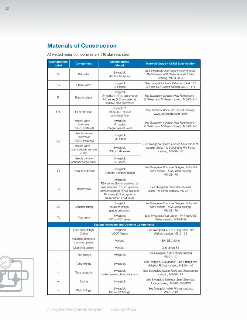
Materials of ConstructionAllwettedmetalcomponentsare316stainlesssteel.
Configuration Label
ComponentManufacturer,
ModelMaterial Grade / ASTM Specification
BV BallvalveSwagelok
40Gor40series
SeeSwagelokOne-Piece Instrumentation Ball Valves—40G Series and 40 Series
catalog,MS-02-331
CV CheckvalveSwagelokCH series
SeeSwagelokCheck Valves—C, CA, CH, CP, and CPA Seriescatalog,MS-01-176
FI Flowindicator
SwagelokM1 series(1/4 in.systems)orM3 series(1/2 in.systems)variableareaflowmeter
SeeSwagelokVariable Area Flowmeters— G Series and M Seriescatalog,MS-02-346
FFL Filter-fastloopTornado™
Model601or602centrifugalfilter
SeeTornadoModel601or602catalog,www.apluscorporation.com
NV
Needlevalve—flowmeter
(1/4 in. systems)
SwagelokM1 series
integralneedlevalve
SeeSwagelokVariable Area Flowmeters— G Series and M Seriescatalog,MS-02-346
Needlevalve—flowmeter
(1/2 in. systems)
Swagelok12N series
SeeSwagelokSevere-Service Union Bonnet Needle Valves—N Series and HN Series
catalog,MS-01-168
Needlevalve—optionalgrabsample
outlet
Swagelok3Nor12N series
Needlevalve—optionalpurgeoutlet
Swagelok3Nseries
PI PressureindicatorSwagelok
B modelpressuregauge
SeeSwagelokPressure Gauges, Industrial and Process—PGI Series catalog,
MS-02-170
RV Reliefvalve
SwagelokR3Aseries(1/4 in.systems,allsealmaterials;1/2in.systems,perfluorocarbonFFKMseals)orR4 series(1/2 in.systems,fluorocarbonFKMseals)
SeeSwagelokProportional Relief Valves—R Seriescatalog,MS-01-141
SN SnubberfittingSwagelok
snubberfittings-gauge protectors
SeeSwagelokPressure Gauges, Industrial and Process—PGI Series catalog,
MS-02-170
PV PlugvalveSwagelok
P4TorP6T seriesSeeSwagelokPlug Valves—P4T and P6T
Series catalog,MS-01-59
System Hardware and Optional Components
—Facesealfittings,
O-ringSwagelok
VCO® fittingsSeeSwagelokVCO O-Ring Face Seal
Fittingscatalog,MS-01-28
—Mountingbrackets,mountingplates
Various 304SS/A240
— Mountingscrews Various 300seriesSS
— Pipefittings SwagelokSeeSwagelokPipe Fittingscatalog,
MS-01-147
— Tubefittings SwagelokSeeSwagelokGaugeable Tube Fittings and
Adapter Fittingscatalog,MS-01-140
— TubesupportsSwagelok
boltedplasticclampsupportsSeeSwagelokTubing Tools and Accessories
catalog,MS-01-179
— Tubing SwagelokSeeSwagelokStainless Steel Seamless
Tubing catalog,MS-01-153-SCS
— WeldfittingsSwagelok
Micro-Fit®fittingsSeeSwagelokWeld Fittingscatalog,
MS-01-149

A Swagelok Pre-Engineered Subsystem Fast Loop Module.
13
TestingEverySwagelokFLMsubsystemisshell
testedwithnitrogenat145psig(10bar)toa
requirementofnodetectableleakagewitha
liquidleakdetector.
Seeindividualvalveproductcatalogsfor
shutofftestinginformation.
Cleaning and PackagingAllSwagelokFLMsubsystemsarecleaned
inaccordancewithSwagelokStandard
Cleaning and Packaging (SC-10),MS-06-62.
Pressure-Temperature RatingsRatingsarelimitedto:
• 212°F(100°C)hightemperaturelimitwithsilicone-filledgauges.
• 25°F(–4°C)lowtemperaturelimitwithoptionalreliefvalves.
System Size 1/4 in. 1/2 in.
Temperature°F (°C)
Working Pressurepsig (bar)
0(–17)to50 (10) 1450(100) —
50(10)to150 (65) 1450(100) 1500(103)
250(121) 1450(100) —
300(148) 1000(68.9) —
A Swagelok Pre-Engineered Subsystem Fast Loop Module
14
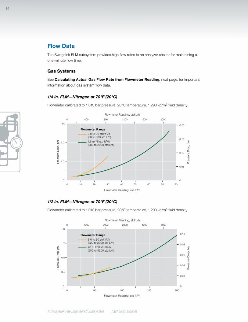
Flow DataTheSwagelokFLMsubsystemprovideshighflowratestoananalyzershelterformaintaininga
one-minuteflowtime.
Gas Systems
SeeCalculating Actual Gas Flow Rate from Flowmeter Reading,nextpage,forimportant
informationaboutgassystemflowdata.
1/4 in. FLM—Nitrogen at 70°F (20°C)
Flowmetercalibratedto1.013barpressure,20°Ctemperature,1.293kg/m3fluiddensity.
1/2 in. FLM—Nitrogen at 70°F (20°C)
Flowmetercalibratedto1.013barpressure,20°Ctemperature,1.293kg/m3fluiddensity.
FlowmeterReading,stdL/h
0 0
1.0
2.0
3.00.20
0.10
0.15
0.05
0 20 10 40 30 60 70 50 80
0 400 800 1200 1600 2000
0 0
1,0
2,0
3,00,20
0,10
0,15
0,05
0 20 10 40 30 60 70 50 80
0 400 800 1200 1600 2000
0
0.020
0.010
0.015
0.005
0 400 800 1200 1600 2000
US
EURO
JAPAN
FlowmeterReading,stdft3/h
Press
ureDrop,psi
Press
ureDrop,bar
Flowmeter Range
3.0to30stdft3/h(80to800stdL/h)
7.5to75stdft3/h(200to2000stdL/h)
FlowmeterReading,stdL/h
0 0
0.8
0.4
1.2
1.6
0.10
0.06
0.08
0.04
0 50 100 200150
0.02
0 1000 2000 3000 4000 5000
0 0
0,8
0,4
1,2
1,6
0,10
0,06
0,08
0,04
0 50 100 200150
0,02
0 1000 2000 3000 4000 5000
0
0.010
0.006
0.008
0.004
0.002
0 1000 2000 3000 4000 5000
US
EURO
JAPAN
FlowmeterReading,stdft3/h
Press
ureDrop,psi
Press
ureDrop,bar
Flowmeter Range
8.0to80stdft3/h(220to2200stdL/h)
20to200stdft3/h(550to5500stdL/h)
A Swagelok Pre-Engineered Subsystem Fast Loop Module.
15
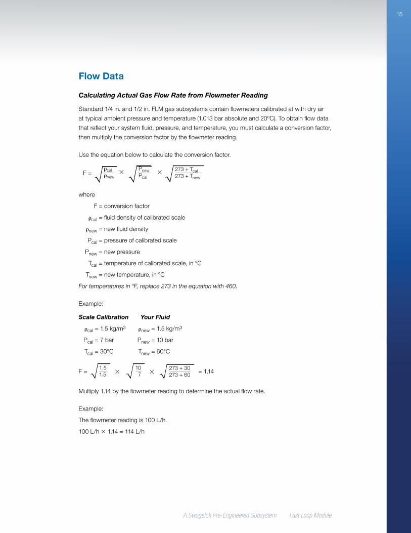
Calculating Actual Gas Flow Rate from Flowmeter Reading
Standard1/4in.and1/2in.FLMgassubsystemscontainflowmeterscalibratedatwithdryair
attypicalambientpressureandtemperature(1.013barabsoluteand20ºC).Toobtainflowdata
thatreflectyoursystemfluid,pressure,andtemperature,youmustcalculateaconversionfactor,
thenmultiplytheconversionfactorbytheflowmeterreading.
Usetheequationbelowtocalculatetheconversionfactor.
where
F=conversionfactor
cal=fluiddensityofcalibratedscale
new=newfluiddensity
Pcal=pressureofcalibratedscale
Pnew=newpressure
Tcal=temperatureofcalibratedscale,inC
Tnew=newtemperature,inC
For temperatures in F, replace 273 in the equation with 460.
Example:
Scale Calibration Your Fluid
cal=1.5kg/m3 new=1.5kg/m3
Pcal=7bar Pnew=10bar
Tcal=30C Tnew=60C
Multiply1.14bytheflowmeterreadingtodeterminetheactualflowrate.
Example:
Theflowmeterreadingis100L/h.
100L/h1.14=114L/h
F=calnew
PnewPcal
273+Tcal273+Tnew
F=1.51.5
107
273+30273+60
=1.14
Flow Data

A Swagelok Pre-Engineered Subsystem Fast Loop Module
16
Flow Data
Liquid Systems
1/4 in. FLM—Water at 70°F (20°C)
Flowmeter Calibration
EverySwagelokflowmeterisfactorycalibratedtoitsmedia,flowrange,andaccuracyclass
usingclean,dryairforair-flowrangemodelsandwaterforwater-flowrangemodels.Formore
information,seetheSwagelokVariable Area Flowmeterscatalog,MS-02-346.
1/2 in. FLM—Water at 70°F (20°C)
WaterFlow,L/h
0 0
1.5
2.0
1.0
0.5
2.5
3.00.20
0.10
0.15
0 5.0 10 2015 25
0.05
0 20 40 60 80
0 0
1,5
2,0
1,0
0,5
2,5
3,00,20
0,10
0,15
0 5,0 10 2015 25
0,05
0 20 40 60 80
0
0.020
0.010
0.015
0.005
0 20 40 60 80
US
EURO
JAPAN
WaterFlow,U.S.gal/h
Press
ureDrop,psi
Press
ureDrop,bar
Flowmeter Range
1.6to16U.S.gal/h(6.0to60L/h)
2.5to25U.S.gal/h(10to100L/h)
WaterFlow,L/h
0 0
15
20
10
5.0
25
302.0
1.0
1.5
0 50 100 200150 250
0.5
0 200 400 600 800
0 0
15
20
10
5,0
25
302,0
1,0
1,5
0 50 100 200150 250
0,5
0 200 400 600 800
0
0.20
0.10
0.15
0.05
0 200 400 600 800
US
EURO
JAPAN
WaterFlow,U.S.gal/h
Press
ureDrop,psi
Press
ureDrop,bar
Flowmeter Range
16to160U.S.gal/h(63to630L/h)
25to250U.S.gal/h(100to1000L/h)
A Swagelok Pre-Engineered Subsystem Fast Loop Module.
17
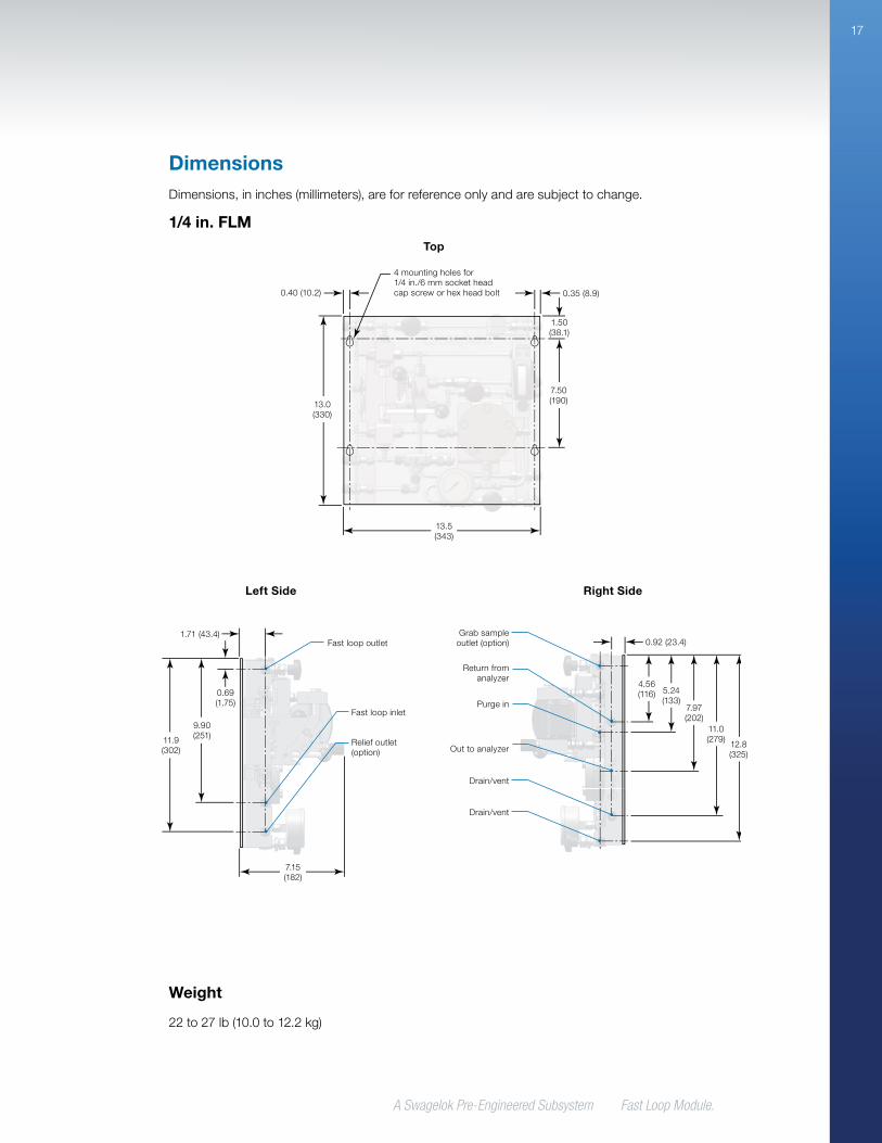
DimensionsDimensions,ininches(millimeters),areforreferenceonlyandaresubjecttochange.
Top
Left Side Right Side
1/4 in. FLM
Fastloopinlet
Fastloopoutlet
Reliefoutlet(option)
7.15(182)
1.71(43.4)
11.9(302)
9.90(251)
0.69(1.75)
7.50(190)
1.50(38.1)
13.0(330)
13.5(343)
4mountingholesfor1/4 in./6 mmsocketheadcapscreworhexheadbolt 0.35(8.9)0.40(10.2)
0.92(23.4)
4.56(116) 5.24
(133)7.97(202)
11.0(279)
12.8(325)
Returnfromanalyzer
Outtoanalyzer
Grabsampleoutlet(option)
Purgein
Drain/vent
Drain/vent
Weight
22to27lb(10.0to12.2kg)
A Swagelok Pre-Engineered Subsystem Fast Loop Module
18
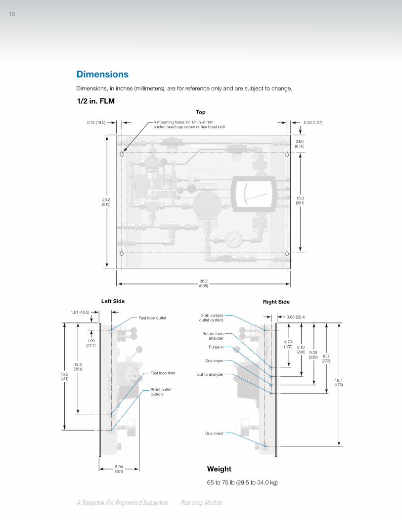
DimensionsDimensions,ininches(millimeters),areforreferenceonlyandaresubjecttochange.
1/2 in. FLMTop
Left Side Right Side
Fastloopinlet
Fastloopoutlet
Reliefoutlet(option)
5.94(151)
1.81(46.0)
16.2(411)
13.8(351)
1.09(27.7)
0.50(1.27)
2.66(67.6)
26.2(665)
15.0(381)
20.2(513)
0.75(19.0) 4mountingholesfor1/4in./6mmsocketheadcapscreworhexheadbolt
6.70(170)
18.7(475)
8.10(206) 9.39
(239) 10.7(272)
0.88(22.4)
Returnfromanalyzer
Outtoanalyzer
Grabsampleoutlet(option)
Purgein
Drain/vent
Drain/vent
Weight
65to75lb(29.5to34.0kg)
A Swagelok Pre-Engineered Subsystem Fast Loop Module.
19
FLM- G4 -1 2 M E B -A 1 S4 KZ
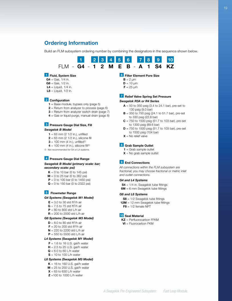
Ordering InformationBuildanFLMsubsystemorderingnumberbycombiningthedesignatorsinthesequenceshownbelow.
2 41 3 5 6 7 8 9 10
1 Fluid, System Size G4 =Gas,1/4in. G8 =Gas,1/2in. L4 =Liquid,1/4in. L8 =Liquid,1/2in.
2 Configuration 1 =Basemodule,bypassonly(page 5) 2 =Returnfromanalyzertoprocess(page 6) 3 =Returnfromanalyzerswitchdrain(page 7) 4 =Gasorliquidpurge,manualdrain(page 8)
3 Pressure Gauge Dial Size, Fill
Swagelok B Model
1 =63mm(21/2in.),unfilled 2 =63mm(21/2in.),siliconefill 3 =100mm(4in.),unfilled➀ 4 =100mm(4in.),siliconefill➀➀ NotrecommendedforG4orL4systems.
6 Filter Element Pore Size B =2µm D =10µm F =25µm
7 Relief Valve Spring Set Pressure
Swagelok R3A or R4 Series
A =50to350psig(3.4to24.1bar),pre-setto130psig(9.0bar)
B =350to750psig(24.1to51.7bar),pre-setto330psig(22.8bar)
C =750to1500psig(51.7to103bar),pre-setto1300psig(89.6bar)
D =750to1500psig(51.7to103bar),pre-setto1500psig(104bar)
X =Noreliefvalve
9 End Connections
All connections within the FLM subsystem are fractional; you may choose fractional or metric inlet and outlet connections.
G4 and L4 Systems
S4 =1/4in.Swageloktubefittings 6M =6mmSwageloktubefittings
G8 and L8 Systems
S8 =1/2Swageloktubefittings 12M =12mmSwageloktubefittings F8 =1/2femaleNPT
10 Seal Material KZ =PerfluorocarbonFFKM VI =FluorocarbonFKM
8 Grab Sample Outlet 1 =Grabsampleoutlet X =Nograbsampleoutlet
4 Pressure Gauge Dial Range
Swagelok B Model (primary scale: bar; secondary scale: psi)
K =0to10bar(0to145psi) M =0to25bar(0to362psi) P =0to100bar(0to1450psi) Q =0to150bar(0to2322psi)
5 Flowmeter Range
G4 Systems (Swagelok M1 Model)
E =3.0to30stdft3/hair G =7.5to75stdft3/hair P =80to800stdL/hair R =200to2000stdL/hair
G8 Systems (Swagelok M3 Model)
D =8.0to80stdft3/hair F =20to200stdft3/hair N =220to2200stdL/hair P =550to5500stdL/hair
L4 Systems (Swagelok M1 Model)
F =1.6to16U.S.gal/hwater H =2.5to25U.S.gal/hwater Q =6.0to60L/hwater S =10to100L/hwater
L8 Systems (Swagelok M3 Model)
K =16to160U.S.gal/hwater M =25to250U.S.gal/hwater X =63to630L/hwater Z =100to1000L/hwater
Swagelok,Micro-Fit,VCO—TMSwagelokCompany,Tornado—TMA+Manufacturing,LLC©2011–2012SwagelokCompany, MS-02-361, R4
Safe Product SelectionWhen selecting a product, the total system design must be considered to ensure safe, trouble-free performance. Function, material compatibility, adequate ratings, proper installation, operation, and maintenance are the responsibilities of the system designer and user.
Caution: Do not mix or interchange Swagelok product components with those of other manufacturers.
Warranty InformationSwagelokproductsarebackedbyTheSwagelokLimited
LifetimeWarranty.Foracopy,visitswagelok.comorcontact
yourauthorizedSwagelokrepresentative.
Regulatory Compliance
Europe
• PressureEquipmentDirective(PED)97/23/EC
• AtmospheresExplosiveDirective(ATEX)94/9/EC
• RestrictionofHazardousSubstancesDirective(RoHS)
2002/95/EC
Americas
• Hazardouslocationelectricalapproval(CSA/UL)
• CRNregisteredinCanada(individualcomponentsof
assembly)
ContactyourauthorizedSwagelokrepresentativeforspecific
assemblycomplianceapprovalsandcertificationsavailablefrom
themanufacturer.