fasteners for safety critical, cracked concrete & …
TRANSCRIPT

Fasteners FOR SAFETY CRITICAL, CRACKED CONCRETE & SEISMIC APPLICATIONS

RONDO CERT-R-FIx®
CONTENTS:
COMPONENTS 4
PRODUCTDATASPECIFICATIONS 5
TYPICALAPPLICATIONSCEILINGS (DIRECT FIX) 6CEILINGS (CLOSE-ADJUSTABLE) 8CEILINGS (ADJUSTABLE) 9WALLS (INTERNAL) 10WALLS (INTERNAL FURRING) 12WALLS (EXTERNAL) 13TOP HATS 15
INSTALLATIONDETAILSTYPICAL APPLICATION DETAILS 16TROUBLESHOOT GUIDE 17
TECHNICALANDLOADDATA 19
NON-SAFETYCRITICALAPPLICATIONS 22
PACKAGINGDETAILS 23
IMPORTANT NOTES: Rondo recommends its products and systems are installed by a qualified tradesperson and according to the relevant codes and standards. Rondo recommends that before acting on any advice or opinion in this manual, you should seek professional advice in light of your own architectural and building requirements.
STANDARDSANDBUILDINGCODESRondo Building Services uses the following Standards in its procurement, manufacturing, testing, design and marketing policies for compliance with the respectiveBuilding Codes of Australia and New Zealand:
Design Standards:AS/NZS1170 Part 0 Structural design actions
-General PrinciplesAS/NZS1170 Part 1 Structural design actions
-Permanent imposed and other actions
AS/NZS1170 Part 2 Structural design actions -Wind actions
AS1170 Part 4 Structural design actions -Earthquake actions in Australia
NZS1170 Part 5 Structural design actions -Earthquake actions in New Zealand
AS/NZS4600 Cold-formed steel structuresAS5216 Design of post-installed and
cast-in fastenings for use in concrete
Steel is purchased to the following standard:
Quality Assurance:ISO 9001 Quality Management
Systems
Environmental PerformanceISO 14001 Environmental
Management Systems
NCC Building code of Australia volumes 1 and 2
MEANSOFCOMPLIANCEWITHAS5216
European Technical Assessment (ETA) In accordance with European Assessment Document (EAD) 330232.
Note: Single point fastening such as suspended ceiling fasteners can only be verified in accordance with EAD 330232
Rondo CERT-R-FIX® fasteners are certified under ETA-15/0514 in accordance with EAD 330232-00-0601
If using un-cracked concrete design capacities:
• Concrete to be assessed for condition in accordance with AS5216 CL 3.3
• Rondo recommends assuming cracked concrete condition as the fastener locations throughout the slab will likely occur in both tension and compression zones
RONDO CERT-R-FIX® FASTENERS
PART NO DESCRIPTION AS5216 COMPLIANT
CRACKED CONCRETE APPROVAL (OPTION 1)
SEISMIC APPROVAL
C1
FIRE RATED
CH06 M6 x 43mm Fastener YES YES YES YES
CH06 M6 x 60mm Fastener YES YES YES YES
CH06 M6 x 80mm Fastener YES YES YES YES
CH10 M10 x 60mm Fastener YES YES YES YES
CT06 M6 x 40mm Fastener with 6mm Male Thread YES YES YES YES
Is Rondo® Anchoring Application Safety Critical
Fastener must comply with: • NCC
• AS5216
Rondo CERT-R-FIX® can be used OR
Refer to page 22
Rondo CERT-R-FIX®
Yes Unsure No
Rondo Safety Critical Applications:
• Ceiling Framing • External Wall Framing
• Internal Fire Rated Wall Framing • Some Internal Wall Framing Supporting FF&E
INTRODUCTIONOur new range of fasteners complement our existing wall and ceiling systems and are suitable for Safety Critical, Cracked Concrete, Seismic and Fire Rated Applications.
SUITABLEFOR• Safety critical applications
• Cracked concrete
• Seismic applications
• Fired rated applications
SPECIALFEATURES• Fully code compliant range of fasteners complements our
wall & ceiling systems
• Offers a single point fastener 40mm embedment solution backed with an ETA
• 6mm ETA certified fasteners are faster to install than 8mm fasteners – speeding up installation time and reducing labour costs
• 40mm embedment depth means that the concrete slab doesn’t need to be x-rayed in most applications
• 10mm fastener complements our head and base brackets, suitable for Steel Stud, MAXIjamb® and DUPLEX Stud® profiles
• Allows you to source fasteners and framing from the one supplier
• Backed by our product guarantee and technical design support

5 4
RONDO CERT-R-FIx® components
INDIVIDUALPARTS
ASSEMBLEDBRACKETS
CH06 CT06CH10
CC06 123 826
DELIVERY,STORAGE&HANDLING• All materials shall be delivered in their
original, unopened packages and stored for as short a time as possible, in an enclosed shelter providing protection from exposure to the elements and damage by/to other trades. Damaged, deteriorated or obviously faulty material is not to be installed and shall be removed from the premises.
• Materials should be handled in such a manner as to prevent racking distortion or physical damage.
CERT-R-FIX products are available to purchase as individual fastener components or as a completely assembled Rondo bracket via special order.
A239C STSLCA124C
product data specifications
CERT-R-FIX®CH06/CH10FASTENERS
PART NOFASTENER DIAMETER
(mm)
SCREW LENGTH (L)
(mm)
CORE DIAMETER (dk)
(mm)
THREAD OUTER DIAMETER (ds)
(mm)
SOCKET SIZE (sw) (mm)
CH06 6 43 5.1 7.5 13
CH06 6 60 5.1 7.5 13
CH06 6 80 5.1 7.5 13
CH10 10 60 9.1 12.6 15
L
dk dssw
CERT-R-FIX®CT06SCREWFASTENER
PART NOEXTERNAL THREAD
DIAMETER (mm)
EXTERNAL THREAD
LENGTH (eL) (mm)
FASTENER DIAMETER
(mm)
SCREW LENGTH (L)
(mm)
CORE DIAMETER (dk)
(mm)
THREAD OUTER DIAMETER (ds)
(mm)
SOCKET SIZE (sw)
(mm)
CT06 6 12.5 6 40 5.1 7.5 10
L
eL
dk dssw
CERT-R-FIX®CC06COUPLER
PART NOINTERNAL THREAD
DIAMETER (mm)
COUPLER LENGTH (L)
(mm)
SOCKET SIZE (sw)
(mm)
CC06 6 25 13
L
sw
INDIVIDUAL PARTS
CH06 (43mm) CERT-R-FIX® M6 x 43mm Fastener with Hex Head (TSM6 x 43 SW13)
CH06 (60mm) CERT-R-FIX® M6 x 60mm Fastener with Hex Head (TSM6 x 60 SW13)
CH06 (80mm) CERT-R-FIX® M6 x 80mm Fastener with Hex Head (TSM6 x 80 SW13)
CH10 CERT-R-FIX® M10 x 60mm Fastener with Hex Head (TSM10 x 60 SW15)
CT06 CERT-R-FIX® M6 x 40mm Fastener with 6mm Male Thread (TSM6x40 M6x11 SW10)
CC06 CERT-R-FIX® M6 x Hex M6 Female Rod Coupler
123ø5.3mm Zinc Plated Soft Steel Rod - M6 threaded full length (65mm, 85mm, 100mm, 120mm, 150mm and 180mm)
826 M6 Nut
ASSEMBLED BRACKETS
A239CDFC for 129/308/309A Furring Channel to Concrete/Masonary with CT06 (40mm), CC06, 826 & 123
A124CDFC for 125/127/128 Top Cross Rail to Concrete/Masonary - with CT06 (40mm), CC06, 826 & 123
STSLCAcoustic Isolation DFC for 129/308/309A Furring Channel with CT06 (40mm), CC06, 826 & 123

7 6
TYPICAL APPLICATION DETAILS: CEILINGS (Direct Fix)
The following details showcase the many uses of the Rondo CERT-R-FIX® range and are intended as a reference for possible installation scenarios.Please refer to the Rondo professional design manual or contact a Rondo representative for specific installation requirements and capabilities relevant to your project.
INSTALLATION OF 247 SUSPENSION BRACKET
INSTALLATION OF BETAGRIP® BG01
INSTALLATION OF 237 CLIP OR 157 CLIP
INSTALLATION OF BETAGRIP® 3 BG03-NTB
INSTALLATION OF THE-CLIP® (275) INFINITI® CLIP TO FURRING CHANNEL
1
7
3
9
115
INSTALLATION OF 547 SUSPENSION BRACKET
INSTALLATION OF BETAGRIP® BG02
INSTALLATION OF 124 CLIP
INSTALLATION OF BETAFIL® BG05 / BG05K
INFINITI® CLIP TO TOP CROSS RAIL
2
8
4
10
6
CERT-R-FIX® CH06 FASTENER (M6 X 43mm) and CH06 FASTENER (M6 X 60mm)
CH06 (43mm) Fastener
CH06 (43mm) Fastener
CH06 (43mm) Fastener
CH06 (43mm) Fastener
THE-Clip® (275)
CH06 (60mm) Fastener
BG03-NTB BETAGRIP®
BG05 / BG05K BETAFIL®
BG02 BETAGRIP®
CH06 (43mm) Fastener
CH06 (43mm) Fastener
CH06 (43mm) Fastener
237 Clip or 157 Clip
547 Suspension Bracket
247 Suspension Bracket
121 Suspension Rod
121 Suspension Rod
Top Cross Rail
Top Cross Rail
139 Interchange Clip
TCR-INFIN090 Infinti® Clip
INFINITI® Clip
Furring Channel
124 Clip
CH06 (43mm) Fastener
CH06 (43mm) Fastener
CH06 (43mm) Fastener
BETAGRIP® Clip
129 or 308 Furring Channel
Furring Channel

9 8
TYPICAL APPLICATION DETAILS: CEILINGS (adjustable)CERT-R-FIX® CT06 FASTENER (M6 X 40mm), CC06 COUPLER (M6 X 25mm) & 123 THREADED ROD (65mm, 85mm, 100mm, 120mm, 150mm and 180mm)
DIRECT FIX APPLICATION USING 239 CLIP UP TO 180mm SUSPENSION DROP
16
A124C CLIP ASSEMBLY UP TO 180mm SUSPENSION DROP
STSLC ACOUSTIC MOUNT UP TO 180mm SUSPENSION
17
19
701 DUO CLIP UP TO 180mm SUSPENSION
18
A239C and A124C can be ordered as individual parts or as a fully assembled part that includes CT06, CC06, 826 & 123. Lead times and minimum order quantities apply.
TYPICAL APPLICATION DETAILS: CEILINGS (CLOSE - adjustable)CERT-R-FIX® CT06 FASTENER (M6 X 40mm)
INSTALLATION OF 157 CLIP
12
INSTALLATION OF 239 CLIP
13
INSTALLATION OF 701 DUO CLIP
14
INSTALLATION OF 124N CLIP
15
CT06 (40mm) Fastener
CT06 (40mm) Fastener
CT06 (40mm) Fastener
CT06 (40mm) Fastener
826 M6 Nut
239 Clip
Furring Channnel
701 DUO Clip
STSL Acoustic Mount
CC06 Coupler
123 Threaded Rod
40mm Embedment Into Concrete
826 M6 Nut
826 M6 Nut826 M6 Nut
123 Threaded Rod
123 Threaded Rod
124N Clip
123 Threaded Rod
CC06 Coupler
CC06 CouplerCC06 Coupler
CT06 (40mm) Fastener
CT06 (40mm) Fastener
701 DUO Clip
CT06 (40mm) Fastener
CT06 (40mm) Fastener
157 Clip
239 Clip
124N Clip
826 M6 Nut
129 or 308 Furring Channel

11 10
TYPICAL APPLICATION DETAILS: WALLS (INTERNAL)CERT-R-FIX® CH06 FASTENER (M6 X 43mm)
WALL INTERSECTION MASONRY / CONCRETE WALL END
20 21
WALL CORNER, ONE LAYER BOARD
DEFLECTION HEAD TRACK FASTENER
22
24
WALL INTERSECTION, ONE LAYER BOARD
23
TYPICAL APPLICATION DETAILS: WALLS (INTERNAL) (continued)CERT-R-FIX® CH06 FASTENER (M6 X 43mm)
DUPLEX STUD AND DUPLEX BRACKET INSTALLATION
FLEXIBLE TRACK INSTALLATION
25
27
DUPLEX STUD AND DUPLEX BRACKET INSTALLATION
26
NOTES:1. Details shown are for non-fire rated construction only. Fire rated
wall details are to be confirmed with the board manufacturer2. Details shown are for internal non-load bearing walls only3. Details shown may not be suitable for inter-storey drift beyond
H/500 at serviceability limit state. Refer to Rondo when this limit is exceeded
CH06 (43mm) Fastener
CH06 (43mm) Fastener
CH06 (43mm) Fastener
Flexible Track
Wall Track
#8G SD Screw
Duplex Stud
CH06 (43mm) Fastener
CH06 (43mm) Fastener
CH06 (43mm) Fastener
CH06 (43mm) Fastener
Ensure fastener is close to intersecting walls
CH06 (43mm) Fastener
Spacing as per framing specification
100mm MAX100mm MAX
100mm -150mm MAX
100mm MAX to first fixing
point
Spacing as per framing specification
100mm
MA
X
20mmMIN 72mm to first fixing
100mm
MA
X
2/#12G Hex Head HD SD Screws
2/#12G Hex Head HD SD Screws
562 Duplex Stud Bracket
562 Duplex Stud Bracket
CH06 (43mm) Fastener
CH06 (43mm) Fastener
Duplex Stud

13 12
TYPICAL APPLICATION DETAILS: WALLS (internal furring_)CERT-R-FIX® FASTENER RANGE
BETAGRIP® 3 BG03-NTB SYSTEM IMAGE USING CH06 (60mm)
28
239 WALL SYSTEM IMAGE USING CT06 (40mm) FASTENER
STDC WALL SYSTEM IMAGE USING CH06 (80mm)
STWC WALL SYSTEM IMAGE USING CH06 (80mm)
29
31
32
STSLC SYSTEM IMAGE USING CT06, CC06, 826 AND 123
30
TYPICAL APPLICATION DETAILS: WALLS (EXTERNAL)CERT-R-FIX® CH06 FASTENER (M6 X 43mm) or CH10 FASTENER (M10 X 60mm)
STANDARD INSTALLATION OF 92mm SLOTTED HEAD TRACK
33
STANDARD INSTALLATION OF 150mm SLOTTED HEAD TRACK
ALTERNATIVE INSTALLATION OF 150mm SLOTTED HEAD TRACK
STANDARD INSTALLATION OF 92mm WALL TRACK
35
STANDARD INSTALLATION OF 150mm WALL TRACK
36
ALTERNATIVE INSTALLATION OF 150mm WALL TRACK
38
34
37
STSLC Acoustic Mount
CT06 (40mm) Fastener
CC06 Coupler
826 M6 Nut
BG03-NTB BETAGRIP®
239 Clip
CH06 (60mm)Fastener
CT06 (40mm) Fastener
CH06 (43mm)Fastener
CH06 (43mm)Fastener
Wall Track Wall Track
Wall Track
Steel Stud
Steel Stud Steel Stud
Steel Stud
Steel Stud
Steel Stud
CH06 (43mm)Fastener
CH10 (60mm)Fastener
50mm x 50mm x 3mm washer
50mm x 50mm x 3mm washer
CH06 (43mm)Fastener
CH10 (60mm)Fastener
Slotted Deflection Head Track
Slotted Deflection Head Track
Slotted Deflection Head Track
MIN 20mm
MIN 20mm
MIN 20mm
45mm
30mm MIN 40mm
#10G SD Screws Each Side
#10G SD Screws Each Side
#10G SD Screws Each Side
#10G SD Screws Each Side
#10G SD Screws Each Side
#10G SD Screws Each Side
45mm
75mm
75mm
30mm MIN 40mm
CH06 (80mm) Fastener
CH06 (80mm) Fastener
STDC Acoustic Isolation Clip
STWC Acoustic Isolation Clip

15 14
INSTALLATION OF 92mm SLOTTED HEAD TRACK WITH BRACKET
INSTALLATION OF 92mm WALL TRACK WITH BRACKET
39
41
INSTALLATION OF 150mm SLOTTED HEAD TRACK WITH BRACKET
INSTALLATION OF 150mm WALL TRACK WITH BRACKET
40
42
TYPICAL APPLICATION DETAILS: WALLS (EXTERNAL) (continued)CERT-R-FIX® CH06 FASTENER (M6 X 43mm) or CH10 FASTENER (M10 X 60mm)
TYPICAL APPLICATION DETAILS: Top HatsCERT-R-FIX® CH06 FASTENER (M6 X 43mm) or CH10 FASTENER (M10 X 60mm)
TOP HAT CLEAT WITH 2 X CH06 SYSTEM IMAGE
INSTALLATION OF TOP HAT TO CONCRETE
43
45
TOP HAT CLEAT WITH 1 X CH10 SYSTEM IMAGE
44
INSTALLATION OF TOP HAT DIRECT FIX WITH 2 X CH06
46
NOTES:1. Fastener options shown on figure 43 and 44 can be used on Rondo Top Hat Cleats 535, 550, 735 and 750.
2/#12G Hex Head HD SD Screws
Steel Stud / MAXIjamb® Stud
Steel Stud / MAXIjamb® Stud
Steel Stud / MAXIjamb® Stud
Steel Stud / MAXIjamb® Stud
203 Bracket
201 Bracket 205 Bracket
207 Bracket
2/#12G Hex Head HD SD Screws
4/#12G Hex Head HD SD Screws
4/#12G Hex Head HD SD Screws
CH10 (60mm)Fastener
Wall Track
Slotted Deflection Head Track Slotted Deflection
Head TrackMIN 20mm MIN 20mm
#10G SD Screws Each Side
#10G SD Screws Each Side
#10G SD Screws Each Side
#10G SD Screws Each Side
CH10 (60mm)Fastener
CH10 (60mm)Fastener
CH10 (60mm)Fastener
60mm 110mm
110mm60mm
CH06 (43mm)Fastener
CH06 (43mm)Fastener
CH10 (60mm)Fastener
735 / 750 Top Hat Cleat 535 / 550
Top Hat Cleat
2/#12G Hex Head HD SD Screws
Top Hat

17 16
Installation detailsTypical Application Details
STEP 1 Drill a hole using a hammer drill bit* to a minimum embedment depth of 45mm for CH06 & CT06, and to a minimum depth of 65mm for CH10, using the correct diameter drill bit to match.
STEP 2 Clean the hole, ensuring you remove any dust or materials using appropriate engineering controls.
STEP 3 Attach the CERT-R-FIX® fastener to the correct size socket and ensure the fastener is perpendicular to the concrete. Apply pressure against the fastener and rotate to engage the first thread. Continue to tighten the fastener until the flanged head is firmly seated against fixture. Use the maximum torque guide and do not over-torque the fastener.
STEP 4 Look and check that the fastener has been secured properly. Installation is complete.
NOTES:1. The fastener may be untightened a maximum of 10mm2. Head must be undamaged and in contact with the fixture3. Use appropriate engineering controls and PPE as outlined by Safe Work Australia
*Alternatively for CH10 installation, a Hollow Drill Bit can be used (e.g. Heller Set-Safe DE Hollow Drill Bits) which vacuums out the dust. Proceed to Step 3 if this applies.
Installation detailsTroubleshoot Guide
HASTHEHOLEBEENDRILLEDSTRAIGHTATA90°ANGLETOTHECONCRETE?
If the hole has not been drilled perpendicular to the concrete (with a maximum deviation of 5°), installing the CERT-R-FIX® fastener at an angle can cause undue bending moments and possible breakage.
AREYOUUSINGTHECORRECTSIZEDRILLBIT?
The correct size drill bit is imperative for the CERT-R-FIX® fastener to be able to cut its thread into the concrete to obtain its full published capacities and certifications.
HOWOLDISYOURDRILLBIT?
Drill bits that have been worn out can create holes that are too small for the CERT-R-FIX® fastener may cause undue stresses which can become evident either during installation or post installation.
ISYOURDRILLHOLECLEANED?
Unless you are using a hollow drill bit, you will need to clean your drill hole. Not cleaning the hole can build up dust at the bottom of the hole effectively reducing your hole depth to be under the minimum requirements.
DRILL BIT REQUIREMENTS
PART NO
DRILL BIT DIAMETER
CH06 6mm
CH10 10mm
CT06 6mm
UNCLEAN HOLE CLEAN HOLE
MAXIMUM TORQUE GUIDE
PART NO
MAXIMUM TOOL TORQUE
CAPACITY
MAXIMUM INSTALL TORQUE
CH06 160Nm 10Nm
CH10 400Nm 40Nm
CT06 160Nm 10Nm
90°
Applied Tightening Torque
Increased resisting torque due to thread friction into smaller hole
Dust compacting at the bottom
of the hole

hnom
h1
t,fix
19 18
installation details (continued)Troubleshoot Guide
Technical and load dataCERT-R-FIX® CH06 FASTENER (M6 X 43mm)
INSTALLATION PARAMETERS
EMBEDMENT DEPTH (hnom) (mm)
DEPTH OF DRILL HOLE
(h1) (mm)
FIXTURE THICKNESS
(t,fix) (mm)
AS5216 COMPLIANT
CRACKED CONCRETE APPROVAL
SEISMIC APPROVAL C1
FIRE RATED
ZINC COATING
40 MIN ≥ 45 3 MAX YES, REFER TO ETA 15-0514MIN 5
MICRONS
CEILING FASTENERS (TABLE 1)
CHARACTERISTIC VALUES FOR TENSION (kN) SAFETY CRITICAL APPLICATIONS - OPTION 1, CRACKED CONCRETE
STATIC / QUASI-STATIC (NRk,p)
SEISMIC C1 (NRk, p, eq)
FIRE 60MIN, 90MIN (NRk, p, fi)
FIRE 120MIN (NRk, p, fi)
2.44 2.0 0.5 0.4
TRACK / BRACKET FASTENERS (TABLE 2)
DESIGN LOAD RESISTANCE (kN)
MINIMUM EDGE DISTANCE (mm)
STATIC / QUASI-STATIC SEISMIC C1 FIRE (R30 - 90) FIRE (R120)
SHEAR (VRd)
TENSION (NRd)
SHEAR (VRd)
TENSION (NRd)
SHEAR (VRd)
TENSION (NRd)
SHEAR (VRd)
TENSION (NRd)
40 2.33 1.33 2.33 1.33 - - - -
≥60 4.08 1.63 3.76 1.33 - - - -
≥70 4.85 1.63 3.76 1.33 0.5 0.5 0.4 0.4
NOTES:Values in Table 1 assume:1. Assumed concrete Condition for values: Minimum concrete strength - 30MPa, Cracked Concrete, 100mm BMT2. Values are characteristic values, not design values 3. Safety critical applications4. Single point fasteners (option 1)5. Assumed Edge distance ≥62mm6. No annular gap between fixing and fixture7. For fire attack from more than one side, minimum edge distance to be ≥300mm
Values in Table 2 assume:1. Safety or non-safety critical applications2. Assumed concrete Condition for values: Minimum concrete strength - 30MPa, Cracked Concrete, 100mm BMT3. Single anchors ie. Anchor spacing influence has not been considered4. Edge reinforcement factor Ψre , V = 1.05. Some design loads may increase if concrete splitting reinforcement is used.6. No annular gap between fixing and fixture7. Assumed worst case scenario with shear force acting towards edge8. The Fire Design loads include the safety factor for fire exposure resistance of γMs,fire =1.0 and the
partial safety factor for action γMs,fire =1.09. Combined tension and shear loading in accordance with EN 1992-4:2018 and AS 5216:2018 has
not been included in these tables
AREYOUDRILLINGTHEREQUIREDHOLEDEPTH?
CERT-R-FIX® fasteners require a drilled hole slightly deeper then the length of the nominal embedment depth. The deeper drill holes ensures any residual dust do not interfere with the fastener installation.
AREYOU INSTALLINGWITHANIMPACTGUN?WHATIS ITSTORQUEOUTPUT?
Have you checked the CERT-R-FIX® fastener maximum tool torque guide for the impact screw gun? Are you within its limits? Using an impact screw gun with too much torque can put undue stress to the fastener while it is cutting its thread into the concrete.
IS THE RONDO CERT-R-FIX® BEING OVER TIGHTENEDAGAINSTTHEFIXTURE?
Over-tightening the CERT-R-FIX® fastener against the fixture can cause a clamping force that puts undue stress on the CERT-R-FIX® fastener. The CERT-R-FIX® fastener should stop being installed once it is firmly against the fixture, as the load capacity is achieved from cutting a thread into the concrete and not from a nominated torque value.
DRILL HOLE DEPTH REQUIREMENTS
PART NO
MINIMUM DRILLED HOLE
CH06 45mm
CH10 65mm
CT06 45mm
MAXIMUM TOOL TORQUE GUIDE
PART NO
MAXIMUM TOOL TORQUE
CAPACITYCH06 160Nm
CH10 400Nm
CT06 160Nm
INSTALLATION TORQUE GUIDE
PART NO
MAXIMUM INSTALL TORQUE
CH06 10Nm
CH10 40Nm
CT06 10Nm
Required hole is to be slightly longer than
embedment depth to catch residual dust
Possible fracture when extra force is put on the fastener
Fracture may occur
t,fix
hnom
h1
hnom
h1
21
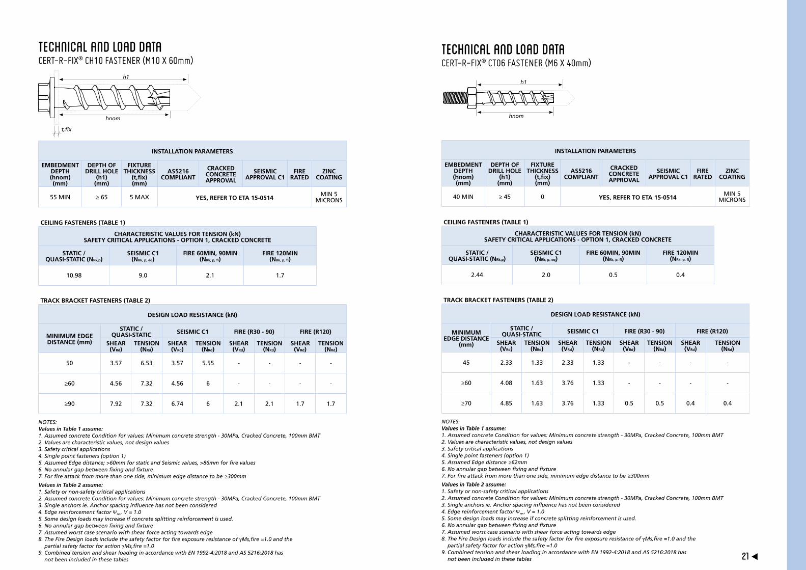
Technical and load dataCERT-R-FIX® CH10 FASTENER (M10 X 60mm)
INSTALLATION PARAMETERS
EMBEDMENT DEPTH (hnom) (mm)
DEPTH OF DRILL HOLE
(h1) (mm)
FIXTURE THICKNESS
(t,fix) (mm)
AS5216 COMPLIANT
CRACKED CONCRETE APPROVAL
SEISMIC APPROVAL C1
FIRE RATED
ZINC COATING
55 MIN ≥ 65 5 MAX YES, REFER TO ETA 15-0514MIN 5
MICRONS
CEILING FASTENERS (TABLE 1)
CHARACTERISTIC VALUES FOR TENSION (kN) SAFETY CRITICAL APPLICATIONS - OPTION 1, CRACKED CONCRETE
STATIC / QUASI-STATIC (NRk,p)
SEISMIC C1 (NRk, p, eq)
FIRE 60MIN, 90MIN (NRk, p, fi)
FIRE 120MIN (NRk, p, fi)
10.98 9.0 2.1 1.7
TRACK BRACKET FASTENERS (TABLE 2)
DESIGN LOAD RESISTANCE (kN)
MINIMUM EDGE DISTANCE (mm)
STATIC / QUASI-STATIC SEISMIC C1 FIRE (R30 - 90) FIRE (R120)
SHEAR (VRd)
TENSION (NRd)
SHEAR (VRd)
TENSION (NRd)
SHEAR (VRd)
TENSION (NRd)
SHEAR (VRd)
TENSION (NRd)
50 3.57 6.53 3.57 5.55 - - - -
≥60 4.56 7.32 4.56 6 - - - -
≥90 7.92 7.32 6.74 6 2.1 2.1 1.7 1.7
NOTES:Values in Table 1 assume:1. Assumed concrete Condition for values: Minimum concrete strength - 30MPa, Cracked Concrete, 100mm BMT2. Values are characteristic values, not design values 3. Safety critical applications4. Single point fasteners (option 1)5. Assumed Edge distance; >60mm for static and Seismic values, >86mm for fire values6. No annular gap between fixing and fixture7. For fire attack from more than one side, minimum edge distance to be ≥300mm
Values in Table 2 assume: 1. Safety or non-safety critical applications2. Assumed concrete Condition for values: Minimum concrete strength - 30MPa, Cracked Concrete, 100mm BMT3. Single anchors ie. Anchor spacing influence has not been considered4. Edge reinforcement factor Ψre , V = 1.05. Some design loads may increase if concrete splitting reinforcement is used.6. No annular gap between fixing and fixture7. Assumed worst case scenario with shear force acting towards edge8. The Fire Design loads include the safety factor for fire exposure resistance of γMs,fire =1.0 and the
partial safety factor for action γMs,fire =1.09. Combined tension and shear loading in accordance with EN 1992-4:2018 and AS 5216:2018 has
not been included in these tables
Technical and load dataCERT-R-FIX® CT06 FASTENER (M6 X 40mm)
INSTALLATION PARAMETERS
EMBEDMENT DEPTH (hnom) (mm)
DEPTH OF DRILL HOLE
(h1) (mm)
FIXTURE THICKNESS
(t,fix) (mm)
AS5216 COMPLIANT
CRACKED CONCRETE APPROVAL
SEISMIC APPROVAL C1
FIRE RATED
ZINC COATING
40 MIN ≥ 45 0 YES, REFER TO ETA 15-0514MIN 5
MICRONS
CEILING FASTENERS (TABLE 1)
CHARACTERISTIC VALUES FOR TENSION (kN) SAFETY CRITICAL APPLICATIONS - OPTION 1, CRACKED CONCRETE
STATIC / QUASI-STATIC (NRk,p)
SEISMIC C1 (NRk, p, eq)
FIRE 60MIN, 90MIN (NRk, p, fi)
FIRE 120MIN (NRk, p, fi)
2.44 2.0 0.5 0.4
TRACK BRACKET FASTENERS (TABLE 2)
DESIGN LOAD RESISTANCE (kN)
MINIMUM EDGE DISTANCE
(mm)
STATIC / QUASI-STATIC SEISMIC C1 FIRE (R30 - 90) FIRE (R120)
SHEAR (VRd)
TENSION (NRd)
SHEAR (VRd)
TENSION (NRd)
SHEAR (VRd)
TENSION (NRd)
SHEAR (VRd)
TENSION (NRd)
45 2.33 1.33 2.33 1.33 - - - -
≥60 4.08 1.63 3.76 1.33 - - - -
≥70 4.85 1.63 3.76 1.33 0.5 0.5 0.4 0.4
NOTES:Values in Table 1 assume:1. Assumed concrete Condition for values: Minimum concrete strength - 30MPa, Cracked Concrete, 100mm BMT2. Values are characteristic values, not design values 3. Safety critical applications4. Single point fasteners (option 1)5. Assumed Edge distance ≥62mm6. No annular gap between fixing and fixture7. For fire attack from more than one side, minimum edge distance to be ≥300mm
Values in Table 2 assume:1. Safety or non-safety critical applications2. Assumed concrete Condition for values: Minimum concrete strength - 30MPa, Cracked Concrete, 100mm BMT3. Single anchors ie. Anchor spacing influence has not been considered4. Edge reinforcement factor Ψre , V = 1.05. Some design loads may increase if concrete splitting reinforcement is used.6. No annular gap between fixing and fixture7. Assumed worst case scenario with shear force acting towards edge8. The Fire Design loads include the safety factor for fire exposure resistance of γMs,fire =1.0 and the
partial safety factor for action γMs,fire =1.09. Combined tension and shear loading in accordance with EN 1992-4:2018 and AS 5216:2018 has
not been included in these tables

23 22
Product Packaging
For non-safety critical applications not covered by AS 5216:2018 the designer should seek technical advice from the fastener supplier in relation to the suitability of the selected fastener.
While the Rondo CERT-R-FIX® range of fasteners are suitable, there are many alternative non-safety critical fasteners available in the market.
The following guide may be applied to the use of non-safety critical fasteners for fixing of head and base tracks of internal non-load bearing and non-fire rated partitions.
NON-SAFETY CRITICAL APPLICATIONS
Maximum Non-safety Critical Fastener Spacing ‘SP’ (mm)
0.375 0.500 0.750 1.000 1.250 1.500
2700 520 390 260 190 150 130
3200 440 330 220 160 130 110
3700 380 280 190 140 110 N/A
4200 330 250 160 120 100 N/A
4700 300 220 150 110 N/A N/A
5200 270 200 130 100 N/A N/A
5700 240 180 120 N/A N/A N/A
6200 220 170 110 N/A N/A N/A
6700 210 160 100 N/A N/A N/A
7200 190 150 N/A N/A N/A N/A
7700 180 140 N/A N/A N/A N/A
8200 170 130 N/A N/A N/A N/A
8700 160 120 N/A N/A N/A N/A
9200 150 110 N/A N/A N/A N/A
WallHeight (mm)
Ultimate DesignPressure
(kPa)
TABLE NOTES:1. Minimum design shear and tensile capacity of non-safety critical fastener = 0.4kN2. Combined shear and tension interaction has been checked to (N*/ØN)+(V*/ ØV)≤1.2
Non-safety critical fastener Internal wall track
(non-fired rated)
Spacing
‘SP’
Spacing
‘SP’
8020
TYPICAL TRACK PLAN DETAIL (SCALE - N.T.S)
CH060043
1 2
Part number
Box quantity
Diameter of drill bit
Drill hole depth
required for fastener
Minimum concrete member depth
Allowable thickness of bracket
/ track fixture
Nominal embedment
depth
Installation torque
Impact drivers
maximum allowable
torque during
installation

RONDO and CERT-R-FIX are registered trademarks of Rondo Building Services Pty Ltd. ABN 69 000 289 207.
First Printed SEPTEMBER 2020. Revised in October 2020 and March 2021.