fast traveling-wave reactor of the … · fast traveling-wave reactor of the channel type vitaliy...
TRANSCRIPT

FAST TRAVELING-WAVE REACTOR OF THECHANNEL TYPE
Vitaliy D Rusov1lowast Victor A Tarasov1 Volodymyr N Vashchenko2Sergei A Chernezhenko1 Andrei A Kakaev1 Oksana I Pantak1
1Department of Theoretical and Experimental Nuclear PhysicsOdessa National Polytechnic University Odessa Ukraine
2State Ecological Academy for Postgraduate Education Kiev Ukraine
Abstract
The main aim of this paper is to solve the technological problems of the TWR based on thetechnical concept described in our priority of invention reference [1] which makes it impossiblein particular for the fuel claddings damaging doses of fast neutrons to excess the 200 dpa limitThus the essence of the technical concept is to provide a given neutron flux at the fuel claddingsby setting the appropriate speed of the fuel motion relative to the nuclear burning wave
The basic design of the fast uranium-plutonium nuclear traveling-wave reactor with a soft-ened neutron spectrum is developed which solves the problem of the radiation resistance of thefuel claddings material
1 Introduction
Today the idea of a wave-like neutron-nuclear burning is almost undisputed Meanwhile in the fieldof physical theory in our opinion there are some problems still unexplored and extremely importantAmong them are the influence of the heat transfer during the temperature and pressure change overa wide range the phase state of the fissile medium and its influence on the existence and stability of anuclear burning wave Such problems as the heterogeneous structure of the core the influence of theradiation-induced defects kinetics in the fuel the heat convection and mixing (liquid or gas fuel) theradiation resistance of the fuel claddings construction materials the ignition modes (initialization)and others also remain unexplored It is also interesting to study the kinetics of the neutron-nuclearburning in combined fissile media (uranium-plutonium uranium-thorium medium with various pre-enrichments in 258U 233U 239Pu and possibly some other fissile nuclides such as 241Pu or Cm) andconsequently the combined uranium-plutonium and thorium-uranium burning waves and perhapseven some others as well as the kinetics of the nuclear burning wave reflection from the boundariesof the medium (neutron reflector) the repeated waves and the burning waves interference
At the same time some of the technological problems of TWR are very actively discussed inthe scientific community today This often leads to a conclusion about the impossibility of suchproject [2] because of a number of its insurmountable disadvantages
bull a high degree of nuclear fuel burn-out (at least 20 on average) which assumes
ndash a high damaging dose from fast neutrons acting on the material of the fuel claddings ( 500dpa)
lowastCorresponding author E-mail siiistenetua
1
arX
iv1
504
0134
0v1
[ph
ysic
sin
s-de
t] 6
Apr
201
5
ndash large gas emission which requires increasing of the inner gas cavity length in the long fuelrods
bull a long active zone which requires the use of the long fuel rods the parameters of which areunacceptable from the exploitation point of view In particular this applies to the parameterscharacterized by significant growth of
ndash the value of the positive void coefficient of reactivity
ndash the hydraulic resistance
ndash the energy consumption for pumping of the coolant through the reactor
bull The problem of spent nuclear fuel associated with the need of the unburned plutonium pro-cessing and disposal of the radioactive waste
However nowadays there are several proposals of the possible principal TWR designs [3ndash14] basedon scientific results [15ndash28] proving the possibility of the theoretical and technical implementationof the slow neutron-nuclear burning modes
A wave reactor on fast neutrons in self-regulating neutron-nuclear mode of the second kind isknown First it was presented in papers [5 6] and its advanced implementation was patented in [14]
Let us consider its drawbacksThis reactor does not implement a slow traveling soliton-like wave of neutron-nuclear burning
mode All the volume of the reactor active zone during its operation is in self-regulating neutron-nuclear mode of the second kind Such reactor is not completely self-regulating but requires somecriticality regulation by the control systems The reactor active zone consists of two or several zonesone of them being a neutron source providing the necessary neutron production at its start andtherefore contains enriched reactor fuel requiring supercritical load and absorbing control rods anda protection system The possible 238U burn-out in non-enriched zones (rdquobreedingrdquo fuel zone) doesnot exceed 10
A wave reactor on fast neutrons is also known [8ndash13] It was proposed by rdquoTerra-powerrdquo tooperate in the so-called standing wave mode
Its drawbacksThe slow traveling soliton-like neutron-nuclear burning is not implemented in this reactor The
entire volume of the reactor active zone represents a neutron-nuclear burning zone during its oper-ation The reactor active zone consists of two zones the central zone being a neutron source andprovides the necessary neutron generation during reactor start-up and operation and therefore con-tains enriched reactor fuel creating supercritical load and contains absorbing control and protectionsystem rods for reactor control During the reactor start-up and some time after the start-up thereactor criticality regulation by external control systems is required Such adjustment is analogousto operation modes of the usual fast reactors with small excessive reactivity and requires the similarcontrol and protection systems Therefore in reactors proposed by rdquoTerra-powerrdquo like in reactorsproposed in [14] a significant advantage of traveling burning wave reactor is absent ndash a completeself-regulation of the reactor active zone and consequently the possibility of significant simplificationand cheapening of the control and protection systems A solution of the excessive shell materialsdamaging dose problem is also absent in reactors proposed by rdquoTerra-powerrdquo
It should be noted however that the rdquoBurns and Roerdquo company specializing in the design andconstruction of the nuclear power stations already offers the architectural and engineering projectsfor the conceptual design of TWR developed by rdquoTerra-powerrdquo on their website
In the papers by H Sekimoto [29ndash65] a design of fast nuclear reactors capable of the travelingwave nuclear burning is studied However the main problem hindering the implementation of atraveling wave reactor ndash the problem of the radiation damaging dose for the fuel claddings ndash is alsonot solved in those studies
2
∆12 u ϕ ψ 〈σdpa〉 ndpa
200
FuelSolution
[cm] [cmday] [cmminus2sminus1] [cmminus2] [barn] burn-upU-Pu cycle
Sekimoto [66] 90 0008 325 middot 1015 32 middot 10 23 1000 32 sim43 NoRusov [67] 200 277 1018 62middot1024 1000 62 sim60 NoPavlovich [68] ndash 0003 ndash 17middot1024 1000 17 sim30 NoFomin [69] 100 007 2 middot 1016 25middot1024 1000 25 sim30 NoFomin [70] 125 17 5 middot 1017 32middot1024 1000 32 sim40 NoChen [71] 216 0046 3 middot 1015 12middot1024 1000 12 sim30 NoTerra Power [72] ndash ndash ndash ndash ndash 175 sim20 No
Th-U cycleTeller [4] 70 014 sim2 middot 1015 86middot1022 1000 096 sim50 YesSeifritz [73] 100 0096 1015 90middot1022 1000 090 sim30 YesMelnik [74] 100 00055 05middot1016 79middot1024 1000 sim80 sim50 No
U-Pu (+ moderator)Example 100 0234 25 middot 1015 92middot1023 100 092 sim20 YesIdeal TWR ndash ndash ndash 1024 100 10 gt20 Yes
Table 1 Results of the numerical experiments of the wave mode parameters based on U-Pu andTh-U cycles
H Sekimoto suggests an interesting idea [39ndash41 46 47] that the wave burning can be implementedin a thermal high-temperature gas reactor for example in the Japanese Experimental workingreactor HTTR if its fuel (enriched in 235U) previously added burnable neutron absorber 157Gd itis interesting And as presented in [49] the results of mathematical modeling wave fuel burningassociated with its local transition in the field of burning in supercritical state will be provided bylocal burnup absorber 157Gd in the burning zone (and in the initiation of the burning wave burnupabsorber 157Gd in the nearest zone of nuclear fuel to an external source of neutrons)
2 Fast TWR of the channel type with a fixed construction
part
In this section we present and justify a possible design of the fast TWR of channel type As notedabove perhaps the most important is to solve the problem of high integral damaging dose of fastneutrons on construction materials in wave nuclear reactors which may reach 500dpa for the nuclearburning wave with the maximum burn-out of 235U However the materials capable of withstandingsuch a radiation load have not been created so far and the maximum achievable radiation exposurefor the reactor metals is 100 divide 200 dpa Indeed as shown in [2] and in Table 1 in [2] none of thesimulated burning wave modes provide the necessary radiation resistance of construction materialsin fuel claddings
The problem of the principal TWR design creation including the solution of the high integraldamaging dose of fast neutrons in construction materials (first of all the fuel rods shells) was setas a base for the invention The specified problem is solved in this framework by a technical imple-mentation of moving nuclear fuel (in which the nuclear burning wave travels) relative to the fuel rodshell The movement speed is adjusted to provide the required integral fluence reduction at the fuelrod shell
Let us consider the following ratio of the integral fluences for metals of the modern operating
3
reactors and the TWR under development
FluencemetalTWR
Fluencemetaloper
sim ΦTWR middot tmetalcampTWR
Φoper middot tmetalcampoper
sim 500 dpa
100 dpa(1)
where ΦTWR and Φoper are the neutron flux densities for the TWR and the modern operating reactorsrespectively And 500 dpa and 100 dpa are the commonly considered values of the radiative resistanceof the construction materials for possible nuclear burning modes with maximal 238U burn-out inTWRs and operating reactors respectively
Let
Φoper sim 1014 neutronscm2 middot s and tcampoper sim 3 years
ΦTWR sim 1017 neutronscm2 middot s (2)
Then from (1) in case (2) we obtain the estimate of the metals campaign time in TWR
tcampTWR sim
500 middot 1014 middot 3100 middot 1017
years sim 15 middot 10minus2 years sim 45 middot 105 s (3)
The time of the fuel nuclear burning in the active zone is
tfuelburn =lfuel
vnuclburn(4)
where lfuel is the length of the active zone containing the fuel vnuclburn is the nuclear burning wavetraveling speed
In order to reduce the radiation damage of the construction materials (fuel rod shell) significantlythe fuel movement speed relative to fixed fuel rod shell (along the channel-like active zone where thefuel rods shells are the most close to nuclear fuel channel shells (Fig 1)) must satisfy the followingrelation
vaz gtlaz
tfuel burn
=lazvnuclburn
lfuel(5)
where laz is the active zone length (fixed constructive part of the active zone in Fig 1)The TWR construction materials campaign time may be written in the following form
tcampmetalTWR asymp lburning wave
vaz + vnuclburnsim λdiff neutrons
vaz + vnuclburn(6)
where lburningwave is the burning wave width (local burning zone) λdiff neutrons is the neutron diffusionlength
The expression (6) may be transformed using (5) into
tcampmetalTWR sim lburning wave
vaz + vnuclburn6
lburning wave
(lazlfuel + 1)vnuclburn(7)
From (7) considering the estimate of the TWR metals campaign (3) we obtain
lfuellaz
gtvnuclburnlburning wave
(tcampmetalTWR + 1) sim
sim 231 middot 10minus5 cms
100 cmmiddot 45 middot 105 s sim 10minus1 (8)
where vnuclburn = 231 middot 10minus5 cms lburning wave sim 100 cm
4
Therefore according to (5) and (7) the following nuclear fuel movement speed may be estimatedas
vaz gtlazlfuel
vnuclburn = 10 middot vnuclburn (9)
Consequently according to (7) for lfuel sim 5 m we obtain laz sim 50 m and according to (5) forvnuclburn = 231 middot 10minus5 cms we obtain vaz sim 10 middot 231 middot 10minus5 cms sim 231 middot 10minus4 cms and the TWRcampaign time
tcampmetalTWR sim laz
vazsim
sim 5 middot 103 cm
231 middot 10minus4 cms middot 3 middot 107 syearsim 072 years (10)
From this example calculation it is clear that the main physical parameters determining the spatialand temporal parameters of the possible TWR construction are ΦTWR vnuclburn and lburningwave
It should be noted that these parameters may be calculated by mathematical modeling of thewave nuclear burning kinetics
Obviously since the fuel movement speed along the active zone must satisfy expression (5) itmay be provided by a technical implementation during the reactor construction It may even beincreased in case the greater reduction of radiation impact at the fuel rod shell is required
For the obtained estimates the following neutron flux density was also obtained
ΦTWR sim 1017 neutronscm2 middot s (11)
This value was chosen by modeling results
bull According to our results for fast U-Pu cylindrical reactor (diameter 70 cm length 400 cm)Φ sim 1019 neutronscm2 middot s [22ndash24]
bull According to Fominrsquos group data for Th-U reactor Φ sim 1016 neutronscm2 middot s [25ndash27]
Considering that flux density will significantly reduce under rdquosofteningrdquo of the spectrum and wavereactor-transmutator for nuclides accumulated due to reactor fuel burning that create the highesthazard for biosystem ideally should operate on neutrons with energy around 1 keV (intermediateneutrons) the abovementioned estimate for the neutron flux was chosen
The burning wave width (local burning zone) lburning wave was chosen 100 cm for the estimate [22ndash27]
Let us note that neutron diffusion length will decrease in case of the spectrum softening due toincrease of the nuclear reactions cross-sections And so does the burning zone length lburning waveThus according to (7) and (8) the nuclear fuel movement speed vnuclburn and the active zone lengthlaz may be reduced
Let us also note that the estimates were made for the hardest conditions of the materials operationhigh burnout and minimal burning speed (non-enriched technical and natural uranium)
Hence in case the neutron-nuclear burning kinetics is implemented in such a way that the fluxdensity is high and the burning wave speed is small ie integral fluence at materials exceeds thecurrently acceptable level then this problem may be solved by increasing the fuel local burning zonemovement speed relative to edgeschannels of the fuel rods shells
To achieve this according to the above said we must ensure that the fuel movement speedalong the fuel channel vaz is greater than the fuel burning wave speed vnuclburn according to theestimate obtained above by technical implementation As shown above these estimates for the
5
chosen parameters are vaz sim 231 middot 10minus4 cms and vnuclburn sim 231 middot 10minus5 cms Ie if one is ableto technically implement the fuel movement speed along the channel just ten times greater than theneutron-nuclear fuel burning wave speed then one would solve the problem of radiation stability ofthe fuel rod shells
For comparison let us give the estimates for the case when an absorbing moderator layer islocated between the fissile fuel and the fuel channel shell metal It reduces neutron flux density atfuel channel shell eg two times relative to the flux density in previous calculations ie ΦTWR sim5 middot 1016 neutronscm2 middot s
Then according to (3) for the TWR metal campaign time we obtain
tcampmetalTWR sim 500 middot 1014 middot 3
100 middot 5 middot 1016years sim
sim 30 middot 10minus2 years sim 90 middot 105 s (12)
And correspondingly according to (8) and (9)
lfuellaz
gt231 middot 10minus5 cms
100 cmmiddot 90 middot 105 s sim 022 (13)
and
vaz gtlazlfuel
vnuclburn asymp 5 middot vnuclburn (14)
Therefore for the considered variant according to (13) in case lfuel = 5 m we obtain laz = 25 mand according to (14) in case vnuclburn sim 231 middot10minus5 cms cms we obtain vaz = 5 middot231 middot10minus5 cms sim116 middot 10minus4 cms and the wave reactor campaign time
tcampmetalTWR sim laz
vazsim
sim 25 middot 103 cm
116 middot 10minus4 cms middot 3 middot 107 syearsim 072 years (15)
Therefore we reduce the active zone length two times from 50 m in the first variant to 25 mfor the second one This is important because it significantly reduces the possible reactor size andincreases the practical implementability of such reactor
The Fig 1 presents a concept scheme of the channel-type reactor with one burning fuel rod Herethe reactor hull shape is cylindrical This is a case of homogeneous active zone of large diameter (sim1-3 m) In the given scheme the fuel movement with the given speed is performed by the movement ofthe bearing frame implemented as a moving part of a hydraulic system Such construction fits wellthe reactor prototype enabling experimental testing of burning wave kinetics and all the principalphysical and construction parameters Let us note that there are three coolants in the proposedconstruction ndash two in-fuel-rod coolants (coolant 1 and 2 in the scheme) while different coolants maybe used and one inter-hull coolant (coolant 3)
The Fig 1 does not present the aspect ratio for the bearing frame of the hydraulic system forthe fuel movement precisely Indeed this figure rather corresponds to the case of a hydraulic systembearing frame implementation based on coaxial cylinders principle (radio antenna principle) whichis widely used in hydraulic cranes and enabling the reduction of reactor construction size
Of course other known and appropriate engineer solutions may be used for the fuel movementsystem construction
6
Figure 1 Concept scheme of TWR prototype with one burning fuel rod A variant of homogeneousactive zone of large diameter (sim1-3m) (1 ndash the nuclear fuel 2 ndash moving construction of the fuelmovement hydraulic system 3 ndash fuel channel shell 4 - fuel rod shell-fuel channel shell 5 ndash hydraulicliquid reservoir hull 6 ndash reactor hull 7 ndash reactor hull cover 8 ndash neutron guide 9 ndash exit pipeline ofin-fuel-rod coolant 1 10 ndash entrance pipeline of in-fuel-rod coolant 1 11 - exit pipeline of in-fuel-rodcoolant 2 12 - entrance pipeline of in-fuel-rod coolant 2 13 - entrance pipeline of inter-hull coolant 314 - exit pipeline of inter-hull coolant 3 15 - entrance pipeline of hydraulic liquid 16 - exit pipelineof hydraulic liquid 17 ndash 24 ndash cylindrical reactor bearing construction elements)
According to the estimates given above it seems reasonable to choose the following geometricalparameters for the long-campaign operating reactor prototype project lfuel sim 5 m laz sim 25divide 50 mhull diameter sim 20divide 30 m height sim 30divide 60 m
The fuel used may be
bull Metallic 238U with small Molybdenum addition (up to 10) for stabilization of cubic uraniumlattice up to room temperatures (melting temperature 1406 K)
bull Metallic 238U with small Chromium addition (up to 8) for stabilization of the radiation formchange of the alloy (melting temperature sim1400 K)
bull Natural uranium as uranium-based metallic alloys
bull 238U dioxide (melting temperature 2820 K)
bull MOX-fuel
bull Cermet fuel
bull Uranium carbides
7
bull Nitride fuel
bull Spent nuclear fuel of many nuclear reactor types eg dioxide nitride fuel dispersive type fueletc
bull Nuclear fuel based on 232Th and 238U
The fuel problem apparently requires additional researchGases used in gas reactors water and metallic coolants used in reactors (eg lithium natrium
stanum lead bismuth mercury lead-bismuth mixture and their complexes) may be used as coolantsin different coolant pump designs (Fig 1)
The specific type of coolant or coolant system providing for thermal-and-physical reactor param-eters given by the wave reactor construction requirements specification may be determined only byproper thermal-and-physical calculations and investigations that are yet only planned
The reactor steel HT9 X18H10T and others may be used as fast reactor construction materialsLet us note that the coolant pipeline system may be used in the prototype to implement neutron
reflector eg water or beryllium and also for accommodation of moderator-absorbent layer near thefuel rod edge to reduce the fuel rod shell radiation damage (Fig 2) This may enable reduction offuel movement speed and respectively the length of the active zone laz
Indeed the radiation damage of the fuel rod shell construction materials may be reduced byreduction of the neutron flux achieved by placing the specific quantity of a specially chosen substancewith proper characteristics of neutron moderator and absorbent between the fissile material and fuelrod shell As a result of the neutrons moderation during the interaction with nuclei of the moderatorthe neutron speed reduces leading to neutron flux density reduction Due to neutron capture byabsorbent the neutron concentration reduces which also leads to neutron flux density reductionIn nuclear reactors physics the moderation efficiency and moderation coefficient are used as thequantitative moderator characteristics
The moderator substance must posses a high moderating efficiency and low moderation coeffi-cient for the optimal solution of the problem of neutron flux density reduction by passing throughmoderator substance The efficiency of the neutron flux density reduction also depends on moderator-absorbent nuclei concentration ie on moderator-absorbent substance density which may be changedby its thermodynamical parameters such as volume pressure and temperature
Assuming that nuclear fuel shell construction material and moderator-absorbent in-between havecylindrical shape the estimate of radial width of moderator-absorbent layer required for the givenneutron flux density reduction may be calculated as follows
Suppose the flux density under moderation reduces due to neutron energy reduction from Efuel
(energy of neutrons released from the nuclear fuel) to Eshell (energy of neutrons at the shell after themoderator) Let atomic number of moderator-absorbent substance to be A The logarithmic meanneutron energy loss (attenuation) during its moderation may be calculated as [75 76]
ξ = 1 +(Aminus 1)2
2AlnAminus 1
A+ 1(16)
The average impact ratio of the neutron being moderated by the moderator nuclei required forneutron energy reduction from Efuel to Eshell equals [75 76]
n =1
ξlnEfuel
Eshell
(17)
Neutron free path in the moderator is [75 76]
λ =1
Σs + Σa
(18)
8
Moderator
Massnum-berA
Meanlogarithmicenergy ξ
densityρgcm3
Impactsrequired formoderatingn
Neutronmean freepath λ
ModeratingabilityξΣs cmminus1
ModeratingcoefficientξΣsΣa
ModeratorlayerwidthRmod cm
Be 9 021 185 11 139 0151 15100 153BeO 25 296
C 12 0158 160 15 356 0044 534H2O 18 0924 10 25 167 0055 416
H2O + 10B 25 100 250D2O 20 11
H 1 10 009 middot 10minus4 23 037 middot 104 265 middot 10minus4 062 middot 105 085 middot 104
He 4 0425 000018 541 104 541 middot 104
He 4 0425 018 541 112 607CO2 198 middot 10minus3
Pb 207 001 113 230 427 00023 075 middot 103 9821Hg 200 001 136 230 301 00033 1571 6928Bi 209 001 98 230 508 00020 1602 11675Sn 118 002 74 115 42 00048 32 4832
Table 2 Moderating and absorbing properties of some substances moderator layer width estimatefor moderating neutron from Efuel = 10 MeV to Emod = 01 MeV
where Σs is the neutron scattering macroscopic cross-section and Σa is the neutron absorption macro-scopic cross-section
The estimates of scattering and absorption cross-sections may be obtained by expressions [75 76]
Σs asymp σsNmoderator andΣa asymp σaNmoderator (19)
where σs and σa are the neutron scattering and absorption microscopic cross-sections respectivelyaveraged over the energy interval from Efuel to Eshell Nmoderator = ρNAA is the moderator nucleidensity where ρ is the moderator density NA is the Avogadro number A is the molar mass of themoderator
Then moderator-absorbent layer width required for the given neutron flux density reduction maybe estimated as follows
Rmoderator asymp λn (20)
Below in Table 2 we present the characteristics of some known moderators and the correspondingmoderator layer width estimates made for neutrons moderating from Efuel = 10 MeV to Eshell =01 MeV ENDF-VII data on cross-sections were used for calculations
The scheme presented at Fig 1 may be easily generalized for a bigger number of fuel rods Forexample Fig 3 presents a possible scheme of seven fuel rods placement on bearing frame driven byhydraulic system of the fuel movement The fixed fuel rods shells and coolant construction is alsoeasily generalized for bigger number of fuel rods by simply replicating its construction presented inFig 1 or Fig 2 In such a way one obtains a heterogeneous active zone
Several possibilities for the reactor implementation arise at this pointFirst an implementation simply generalizing homogeneous large-diameter active zone implemen-
tation is possible Ie a set of several such active zones burning independently from each other oreven sequentially one after another given the corresponding design In case of simultaneous imple-mentation of independent homogeneous active zones we obviously obtain high-power reactor withrelatively short campaign time in comparison to implementation with sequential burning of suchactive zones Such a reactor would be promising for burning of spent nuclear fuel in large amounts
9
In case of sequential burning design one obtains a source of relatively lower power than in theprevious case and with significantly longer campaign time
Second the implementation of the reactor in a form of the thin fuel rods set in a collective burningzone is possible This is analogous to traditional structure of the operating heterogeneous reactors
Let us note that the fixed reactor active zone part becomes very similar to channel type reactorsin this case in particular to LWGR reactors (see Fig 3) This also enables one to benefit from theadvantages of channel reactors such as increased thermal and physical parameters (temperature andpressure) inside the channels
Let us also note that the coolant entrance channel system presented in Fig 1 and Fig 2 may bereplicated and spread by height (length) of the fixed active zone part This would solve the problemof the increased hydraulic resistance for a long active zone Indeed in such approach one can increasethe quantity of coolant entrance channels reducing distance between them by height (length) of theactive zone to provide for technically implementable coolant hydraulic resistance in the pumpingchannels
The examples of the TWR active zone designs given here are clearly only hypothetically possibleLater we need to investigate the kinetics of these reactors by mathematical modeling
Based on the obtained model results we prepare the requirements specifications the assignmentfor developing of the prototypes and development prototypes design them create the developmentprototypes and test them Only after all that the operating reactors may be developed
According to the above given estimates it seems that acceptable geometrical parameters of theoperating reactor with long campaign may be chosen as lfuel sim 5 m laz sim 25divide 50 m hull diametersim 30 m height sim 30divide 60 m
It seems very promising to use a set of 238U spheres filled into a fixed cylinder of the fuel rod shellinstead of the metallic 238U rod (Fig 1 Fig 3) fixed on moving bearing frame implemented as movingpart of the hydraulic system Of course the micro fuel rods or spherical fuel elements analogousto spherical fuel elements of high-temperature gas reactors (eg analogous to THTR-300 [77 78]and VTGR-500 (high temperature gas cooled reactor) [79]) (Fig 4) may be used as a fuel In theconsidered case they slowly move along the fuel rod shell following the movement of the bearingframework platform implemented in form of a moving part of the hydraulic system
Naturally we speak of 238U spheres with sizes appropriate for the required constructive allowancesfor fuel rod shell diameter and moving bearing framework platform diameter to prevent them fallingoutside the platform These may be 238U spheres with protective coating made of Si typical formicro-fuel rods and probably with carbon layer for the neutron spectrum softening Let us notethat these spheres may be of different diameter eg a layer of larger diameter spheres may be locatedbelow to meet construction demands and the micro-fuel elements spheres above them to increasethe fission environment density However all these problems have very little principal significanceat the moment and are to be solved during the specific construction development It is importantfor the process of fuel spheres moving down not to interfere with wave neutron-nuclear fuel burningprocess
Let us also note that the concept of burning fuel movement relative to fuel rods shell made ofconstructive materials considered in this patent also corresponds to a possible active zone constructionbased on the principles already implemented in known high-temperature gas power reactors (reactorsTHTR-300 [77 78] and VTGR-500 (high temperature gas cooled reactor) [79] (Fig 4)) Their activezone is a hull with cone-like bottom with a hole in the center The spherical fuel elements are filledin from above and while burning-out they fall through a hole from the active zone to a spent fuelelements container Such construction of the TWR may require burn-up of the fuel both in theupper part of the active zone and in the lower part which requires locating the neutron source forthe nuclear burning wave burn-up inside the reactor hull or below it
The Fig 5 presents the reactor and reactor equipment location scheme It gives the size ofthe reactor prototype A particle accelerator (eg [80]) or impulse nuclear reactor (eg [81 82]) are
10
Figure 2 Concept scheme of a TWR with one burning fuel rod Homogeneous large-diameter (sim1-3 m) active zone variant (1 ndash the nuclear fuel 2 ndash moving construction of the hydraulic fuel movementsystem 3 ndash metal of the fuel channel 2 4 ndash metal of the fuel channel 1 shell 5 ndash hydraulic liquidreservoir hull 6 ndash reactor hull 7 ndash reactor hull cover 8 ndash neutron guide 9 ndash exit pipeline of in-fuel-rodcoolant 1 10 ndash entrance pipeline of in-fuel-rod coolant 1 11 - exit pipeline of inter-channel coolant2 12 - entrance pipeline of inter-channel coolant 2 13 - entrance pipeline of inter-hull coolant 3 14- exit pipeline of inter-hull coolant 3 15 - entrance pipeline of hydraulic liquid 16 - exit pipeline ofhydraulic liquid 17 ndash 24 ndash cylindrical bearing constructive elements of the reactor 25 ndash hydraulicliquid 26 ndash coolant 1 27 ndash protection shell metal 28 ndash beryllium moderator 29 ndash fuel 30 ndash coolant1 31 - protection shell metal 32 - beryllium moderator 33 - protection shell metal 34 ndash carbon 35- protection shell metal 36 - fuel channel 1 shell metal)
11
Figure 3 Left panel A scheme explaining principles of possible fuel rods placement over movingpart of the fuel rods hydraulic movement system (1 - fuel 2 and 3 - hydraulic fuel movement systembearing frame)Right panel Reactor active zone section scheme (heterogeneous active zone case)
Figure 4 High-temperature reactor with spherical fuel elements construction scheme [77ndash79] Leftpanel high temperature gas cooled reactor scheme with fill-in active zone 1 - fuel elements elevator2 - fuel elements investigation system and burn-out level measurement 3 - damaged elements rodsvault 4 - accumulator 5 - active zone 6 - fuel elements feed system 7 - stepwise fuel elementsseparator 89 - intermediate screw conveyors 10 - process control computer 11 - fuel elementswithdrawal system 12 - directing deviceRight panel HRB reactor scheme with spherical fuel elements 1 ndash gas blower 2 ndash gas blowergear 3 ndash steam generator 4 ndash absorbing reflector rod 7 ndash spherical fuel elements feed line 8 ndashaccumulating block 9 ndash fuel burn-out level measuring device 10 ndash spheres sorting and transportdevice 11 ndash spheres unloading device 12 ndash pipe for spheres unloading 13 ndash fuel feed channel 14 ndashspheres fill-in 15 ndash reflector 16 ndash heat shield 17 ndash coating 18 ndash hull made of preliminarily strainedarmored concrete
12
Figure 5 Wave reactor and reactor equipment arrangement scheme (1 - reactor 2 - acceleratoror impulse reactor 3 - coolant 1 pump system and heat takeoff 4 - coolant 2 pump system andheat takeoff 5 - coolant 3 pump system and heat takeoff 6 - hydraulic liquid pump system 7 -neutrino control system 8 - coolant 3 heat exchanger 9 - coolant 1 heat exchanger 10 - coolant 2heat exchanger 11 - neutron guide 121314 - neutrino detectors 15 - ground surface 16 - reactorhull 17 - neutrino control system communication line)
proposed (see Fig 5) as an external neutron source For the sake of the neutron-nuclear burning waveinitiation (burn-up) optimization the upper fuel part may be enriched by some fissionable nuclide tosuch amount that this enriched area would be in under-critical state Therefore the proposed channeltype TWR construction is a reactor with internal safety [17 18]
It should be noted that both the TWR project and the spent nuclear fuel processing reactorare apparently single-load reactor projects After burning the fuel the reactor installation is buriedAn implementation of the remote neutrino control of the neutron-nuclear burning wave kinetics [24](Fig 5) is obviously required
Conclusions
The basic design of the fast uranium-plutonium nuclear TWR with a softened neutron spectrum isdeveloped It solves the problem of the fuel claddings material radiation resistance This reactormay also work as a processor of the spent nuclear fuel
References
[1] VA Tarasov VD Rusov and VM Vaschenko Nuclear power reactor and method for oper-ating the reactor 2013 2nd Life Nuclear Solutions GmbH HOEFERampPARTNER
[2] V D Rusov V A Tarasov I V Sharph V M Vashchenko E P Linnik T N ZelentsovaM E Beglaryan S A Chernegenko S I Kosenko P A Molchinikolov V P Smolyar andE V Grechan On some fundamental peculiarities of the traveling wave reactor operation 2012URL arXiv12073695v1[nucl-th]
[3] E Teller M Ishikawa and L Wood Completely automated nuclear power reactors for long-term
13
operation In Proceedings of the Frontiers in Physics Symposium American Physical Societyand American Association of Physics Teachers Texas Meeting 1995
[4] E Teller M Ishikawa L Wood R Hyde and J Nuckolls Completely automated nuclearreactors for long-term operation II Toward a concept-level point-design of a high-temperaturegas-cooled central power station system part II In Proceedings of the International Conferenceon Emerging Nuclear Energy Systems ICENESrsquo96 Obninsk Russian Federation pages 123ndash127 Obninsk Russian Federation 1996 Obninsk Russian Federation also available fromLawrence Livermore National Laboratory California publication UCRL-JC-122708-RT2
[5] V Goldin and D Anistratov Fast breeder reactor in the self-regulating neutron-nuclear mode7(10)12ndash31 1995
[6] V Goldin N Sosnin and Y Troshchiev Fast breeder reactor in self-regulating regime of the2nd kind Dokl Akad Nauk Mathematical Physics 358(6)747ndash748 1998
[7] N Takaki and H Sekimoto Potential of CANDLE reactor on sustainable development andstrengthened proliferation resistance Prog Nucl Energy 50114ndash118 2008
[8] J Gilleland C Ahlfeld D Dadiomov R Hyde Y Ishikawa D McAlees J McWhirterN Myhrvold J Nuckolls A Odedra K Weaver C Whitmer L Wood and G Zimmer-man Novel reactor designs to burn non-fissile fuels In Proceedings of the 2008 InternationalCongress on Advances in Nuclear Power Plants (ICAPP 2008) Anaheim CA 2008 AmericanNuclear Society Paper No 8319
[9] R L Garwin Fast reactors when In Presented at Erice Sicily International Seminars onPlanetary Emergencies and Associated Meetings - 43rd Session August 21 2010
[10] Kevan D Weaver J Gilleland C Ahlfeld C Whitmer and G Zimmerman A once-throughfuel cycle for fast reactors Journal of Engineering for Gas Turbines and Power 1321ndash6 April2010
[11] R A Hyde et al Automated nuclear power reactor for long-term operation May 29 2008
[12] R A Hyde et al Method and system for providing fuel in nuclear reactor July 9 2009
[13] C E Ahlfeld et al System and method for operating a modular nuclear fission deflagrationwave reactor September 10 2009
[14] V Goldin et al Active zone of fast U-Pu reactor and operation method ensures working of thereactor in self-neutron-nuclear mode without reactivity margin August 20 2010
[15] S M Feinberg Discussion comment In Record of Proceedings Session B-10 InternationalConference on the Peaceful Uses for Atomic Energy Geneva Switzerland 1958 United Nations
[16] L P Feoktistov Neutron-fission wave Dokl Akad Nauk 309864ndash867 1989
[17] L P Feoktistov Safety - the key moment of revival of nuclear power Successes of physicalsciences 163(8)89ndash102 1993
[18] L P Feoktistov From past towards the future from the hopes about bomb to safe reactor InRFNC-ANRISPh Snezhinsk Russia 1998
[19] H Van Dam The self-stabilizing criticality wave reactor In Proceedings of the Tenth Inter-national Conference on Emerging Nuclear Energy Systems 2000 pages 188ndash197 NRG PettenThe Netherlands 2000
14
[20] A I Akhiezer D P Belozorov F S Rofe-Beketov L N Davydov and Spolnik Z A nthe theory of propagation of chain nuclear reaction in diffusion approximation Yad Fiz 621567ndash1575 1999
[21] AI Akhiezer D P Belozorov F S Rofe-Beketov L N Davydov and Z A Spolnik Thevelocity of slow nuclear burning in two-group approximation Problems of Atomic Science andTechnology (6)276ndash278 2001
[22] V D Rusov V N Pavlovich V M Vashchenko V A Tarasov T N Zelentsova D ALitvinov S I Kosenko V N Bolshakov and EN Khotyaintseva Geoantineutrino spectrumand slow nuclear burning on the boundary of the liquid and solid phases of the Earthrsquos core2004 URL httparxivorgabshep-ph0402039v1
[23] V Rusov V Pavlovich V Vaschenko V Tarasov T Zelentsova V Bolshakov D LitvinovS Kosenko and O Byegunova Geoantineutrino spectrum and slow nuclear burning on theboundary of the liquid and solid phases of the Earthrsquos core J Geophys Res 112B09203 2007
[24] V Rusov V Tarasov and Litvinov D Reactor Antineutrinos Physics URSS Moscow 2008
[25] SP Fomin Yu P Melnik VV Pilipenko and NF Shulga Study of self-organizing regime ofnuclear burningwave in fast reactor Problems of atomic science and technology 45(6)106ndash1132005
[26] SP Fomin Yu P Melnik VV Pilipenko and NF Shulga Self-sustained regime of nuclearburning wave in U-Pu fast reactor with Pb-Bi coolant Probl At Sci Technol (3)156ndash1632007
[27] SP Fomin Yu P Melnik VV Pilipenko and NF Shulga Self-organized regime of nuclearburning wave in safe fast reactor In Proceedings of the 2007 International Congress on Advancesin Nuclear Power Plants (ICAPP 2007) Nice France 2007 Societe Francais DrsquoEnergie Nucleair
[28] VD Rusov EP Linnik VA Tarasov TN Zelentsova V N Vaschenko S I KosenkoM E Beglaryan SA Chernezhenko PO Molchinikolov S Saulenko and OA ByegunovaTraveling wave reactor and condition of existence of nuclear burning soliton-like wave in neutron-multiplicating media Energies 41337ndash1361 2011 doi 103390en4091337
[29] H Sekimoto K Ryu and Y Yoshimura CANDLE The new burnup strategy Nuclear scienceand engineering 139306ndash317 2001
[30] H Sekimoto and K Ryu A new reactor burnup concept rdquoCANDLErdquo In PHYSOR 2000Pittsburgh May 7-11 2000
[31] H Sekimoto and K Ryu Feasibility study on the CANDLE new burnup strategy TransAmerican Nuclear Society 82207ndash208 2000
[32] H Sekimoto and K Ryu A long life lead-bismuth cooled reactor with CANDLE burnup InICENES 2000 pages 198ndash206 Petten The Netherlands September 24-28 2000
[33] H Sekimoto and K Ryu Demonstrating the feasibility of the CANDLE burnup scheme for fastreactors Trans American Nuclear Society 83(45) 2000
[34] H Sekimoto K Ryu and Y Yoshimura CANDLE The new burnup strategy Nucl SciEngin 139306ndash317 2001
[35] H Sekimoto V Toshinsky and K Ryu Natural uranium utilization without enrichment andreprocessing In GLOBAL 2001 Paris France September 9-13 2001
15
[36] H Sekimoto Applications of rdquoCANDLErdquo burnup strategy to several reactors In ARWIF-2001Chester UK October 22-24 2001
[37] H Sekimoto and K Tanaka CANDLE burnup for different core designs In PHYSOR2002Seoul Korea October 7-10 2002
[38] H Sekimoto and K Tanaka Application of CANDLE burnup strategy to small reactors TransAmerican Nuclear Society 87 2002
[39] Y Ohoka and H Sekimoto Application of CANDLE burnup to block-type high temperaturegas cooled reactor In ICONE11 Tokyo Japan April 20-23 2008
[40] H Sekimoto and Y Ohoka Application of CANDLE burnup to block-fuel high temperaturegas reactor In ICAPPrsquo03 Cordoba Spain May 4-7 2003
[41] H Sekimoto and Y Ohoka Application of CANDLE burnup to block-type high temperaturegas cooled reactor for incinerating weapon grade plutonium In GENES4ANP2003 KyotoJAPAN September 15-19 2003
[42] T Takada Y Udagawa and H Sekimoto Simulation study on CANDLE burnup applied to anLBE-cooled metallic fuel fast reactor In GENES4ANP2003 Kyoto JAPAN September 15-192003
[43] E Greenspan P Hejzlar H Sekimoto G Toshinsky and Wade DC New fuel cycle and fuelmanagement options in heavy liquid metal cooled reactors In ANFM 2003 Hilton Head IslandSouth Carolina USA October 5-8 2003
[44] H Sekimoto Contribution of CANDLE burnup to future equilibrium nuclear energy utilizationIn GLOBAL 2003 November 16-20 2003
[45] E Greenspan P Hejzlar H Sekimoto G Toshinsky and Wade D New fuel cycle and fuelmanagement options in heavy liquid metal-cooled reactors Nucl Technol 151177ndash191 2003
[46] Y Ohoka and H Sekimoto Application of CANDLE burnup to block-type high temperaturegas cooled reactor Nucl Engin and Design 22915ndash23 2004
[47] Y Ohoka and H Sekimoto Burnup and temperature effects on CANDLE burnup of block-typehigh temperature gas cooled reactor In ICONE12 Arlington Virginia April 25-29 2004
[48] H Sekimoto Application of rdquoCANDLErdquo burnup to small fast reactor In 5th Int Conf onNuclear Option in Countries with Small and Medium Electricity Grids Dubrovnik CroatiaMay 16-20 2004
[49] Y Ohoka Ismail and H Sekimoto Effects of burnup and temperature distributions to CANDLEburnup of block-type high temperature gas cooled reactor In ICAPPrsquo04 Pittsburgh PA June13-17 2004
[50] Y Ohoka and H Sekimoto Simulation study on CANDLE burnup of high temperature gasreactor Trans American Nuclear Society 92 2004
[51] H Sekimoto Effect of neutron spectra and fuel burnup on CANDLE calculation TransAmerican Nuclear Society 92 2004
[52] Y Ohoka T Watanabe and H Sekimoto Neutron characteristics of CANDLE burnup appliedto HTTR In COE-INES - Indonesia International Symposium 2005 Bandung IndonesiaMarch 2-4 2005
16
[53] H Sekimoto Application of rdquoCANDLErdquo burnup to LBE cooled fast reactor In IAEA-TECDOC-1451 pages 203ndash212 2005
[54] H Sekimoto Y Udagawa and Y Ohoka Application of rdquoCANDLErdquo burnup to fast and thermalreactors In ICAPPrsquo05 Seoul KOREA May 15-19 2005
[55] Y Ohoka H Sekimoto T Watanabe P H Liem Wakana S and Ismail Neutronic charac-teristics of CANDLE burnup applied to block-type high temperature gas cooled reactor InICAPPrsquo05 Seoul KOREA May 15-19 2005
[56] H Sekimoto and Y Udagawa Shut-down and restart simulation of CANDLE fast reactorsTrans American Nuclear Society 93 2005
[57] S Sekimoto H Miyashita Startup of rdquoCANDLErdquo burnup in fast reactor from enriched uraniumcore In ICENESrsquo2005 Brussels Belgium August 21ndash26 2005
[58] H Sekimoto Application of CANDLE burnup strategy for future nuclear energy utilizationProgress in Nucl Energy 4791ndash98 2005
[59] H Sekimoto CANDLE burnup of fast reactor with depleted uranium In 9-th Int ConfrdquoNuclear Safety amp Nuclear Educationrdquo Obninsk Russia 24-27 October 2005
[60] H Sekimoto and Y Udagawa Effects of fuel and coolant temperatures and neutron fluence onCANDLE burnup calculation J of Nucl Sci Technol 43189ndash197 2006
[61] H Sekimoto and S Miyashita Startup of rdquoCANDLErdquo burnup in fast reactor from enricheduranium core Energy Conv Manag 472772ndash2780 2006
[62] H Sekimoto Candle burnup in a fast reactor core and relating nolinear problems In 2nd Inter-national Conf on Quantum Electrodynamics and Statistical Physics (QEDSP2006) KharkovUkraine 19-23 September 2006
[63] Sekimoto H A Light of CANDELE New Burnup Strategy Tokyo Institute of Technology 2005
[64] N Takaki and H Sekimoto Potential of CANDLE reactor on sustainable development andstrengthened proliferation resistance Prog Nucl Energy 50114ndash118 2008
[65] H Sekimoto and K Ryu Introduction of MOTTO cycle to CANDLE fast reactor In Proceedingsof PHYSOR 2010 - Advances in Reactor Physics to Power the Nuclear Renaissance PittsburghPennsylvania USA May 9-14 2010
[66] H Sekimoto and Y Udagava Effects of fuel and coolant temperature and neutron fluence oncandle burnup calculation J Nucl Sci and Technolog 43189ndash196 2006
[67] Vitaliy D Rusov Elena P Linnik Victor A Tarasov Tatiana N Zelentsova Igor V SharphVladimir N Vaschenko Sergey I Kosenko Margarita E Beglaryan Sergey A ChernezhenkoPavel A Molchinikolov Sergey I Saulenko and Olga A Byegunova Traveling wave reactorand condition of existence of nuclear burning soliton-like wave in neutron-multiplying mediaEnergies 4(9)1337ndash1361 2011 ISSN 1996-1073 doi 103390en4091337 URL httpwww
mdpicom1996-1073491337
[68] VN Pavlovich VN Khotyaintsev and EN Khotyaintseva Nuclear burning wave reactorwave parameter control Nuclear Physics and Energetics (11)49ndash56 2010
17
[69] SP Fomin YP Melrsquonik VV Pilipenko and NF Shulga Self-sustained regime of nuclearburning wave in u-pu fast neutron reactor with pb-ni coolant Problems of Atom Sci andTechnology 3156ndash163 2007
[70] SP Fomin YP Melrsquonik VV Pilipenko and NF Shulga Investigation of self-organization ofthe non-linear nuclear burning regime in fast neutron reactor Ann Nucl Energ 321435ndash14562005
[71] X-N Chen W Maschek A Rineiski and E Kiefhaber Solitary burn-up wave solution inmulti-group diffusion-burnup coupled system In ICENESrsquo2007 Istanbul Turkey 2007
[72] KD Weaver J Gilleland C Ahlfeld C Whitmer and G Zimmerman A once-through fuelcycle for fast reactors J Eng for Gas Turbines and Power 1321ndash7 2010
[73] W Seifritz On the burn-up theory of fast soliton reactors Int J Hydrogen Energy 2377ndash821998
[74] YuP Melnik VV Pilipenko AS Fomin SP Fomin and NF Shulga Study of a self-regulatednuclear burn wave regime in a fast reactor based on a thorium-uranium cycle Atomic Energy10749ndash56 2009
[75] GG Bartolomey GA Batrsquo VD Baibakov and MS Altukhov Basic theory and methods ofnuclear power installations calculation Energoatomizdat Moscow 1989 in Russian
[76] S V Shirokov Nuclear Reactor Physics Naukova Dumka Kiev 1992 in Russian
[77] G Kessler Nuclear fission reactors Potentional role and risks of converters and breedersSpringer-Verlag Wien 1983
[78] IY Emelyanov VI Mihan and VI Solonin The construction of nuclear reactors EnergoizdatMoscow 1992 in Russian
[79] BA Dementrsquoev Nuclear energetic reactors Energoatomizdat 1990 in Russian
[80] D Ridiskas H Safa and ML Giacri Conceptual study of neutron irradiator-driven by electronaccelerator In 7 Information Exchange Meeting Jeju (Republic of Korea) 2002
[81] AV Arapov AA Deviatkin IY Drozdov and MV Mochkaev The results of physical start-up of the reactor BR-1M problems of high energy density physics In XII Khariton TopicalScientific Readings Reports Sarov Publishing House of the Federal State Unitary EnterpriserdquoRFNC-VNIIEFrdquo 2010 in Russian
[82] VF Kolesov Aperiodic pulsed reactors Vol1 Sarov Publishing House of FSUE rdquoRFNC-VNIIEFrdquo 2007 in Russian
18
- 1 Introduction
- 2 Fast TWR of the channel type with a fixed construction part
-
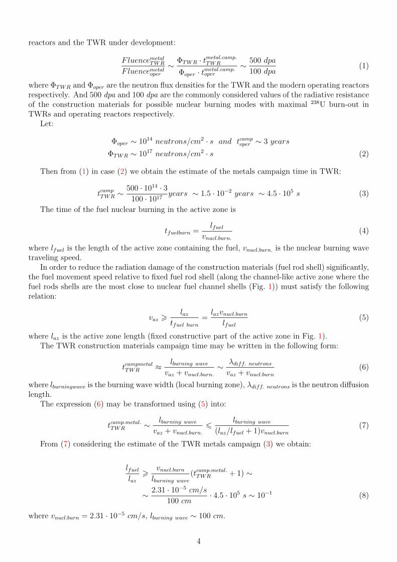
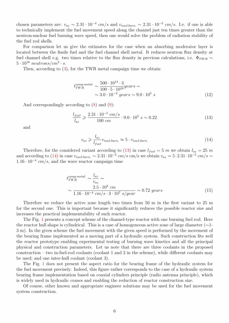
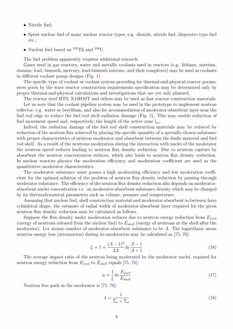
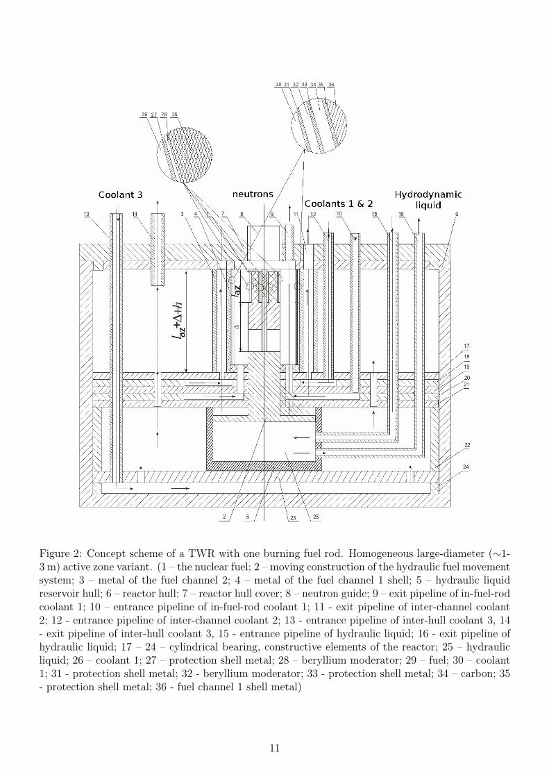