farley initial exam 2010-301 final simulator scenarios
TRANSCRIPT

Appendix D Scenario 1 Outline Form ES-D-1
Facility: Farley Scenario No.: j_ Op-Test No.: FA2O1 0301
Examiners: Operators:
Initial Conditions: 72% RTP; MOL; 1179 ppm Cb, 10000 MWD; rods in Manual;B Train On-Service — B Train Protected; Xe building in -638 pcm
Turnover:
.
e
1C DIG in process of being returned from maintenance condition.STP-27.1 in progress on both units. Surveillance is due again in 3 hours.1A MDAFW PUMP T/C for bearing replacement.Ramp on hold for turnover.Current Risk Assessment is YELLOW and projected is YELLOW.Severe thunderstorm warnings in effect for Southeast Alabama & Western Georgia.
Event Malf Event Type* 1 EventNo. No. Description
I R(RO) Increase reactor power per UOP-3.12 1 l(RO) LT-460 fails LOW
(SRO) TS TS 3.3.1N(BOP or RO) Place letdown in service
3 2 I(BOP) PT-508 fails HIGH4 3 C(RO) IA Running charging pump experiences a shaft shear.
(SRO) TS T.S. condition 3.5.2 Condition A5 4 I (BOP) N-44 has a lower detector failure TS 3.3.1
(SRO) TS6 M(ALL) Loss of off site power occurs on 1 F BUS and reactor fails
to trip. Reactor is tripped by MG set supply breakershaving to be opened. LOSP when RX is tripped. 1-2AEDG does not auto start and cannot be manually started.
7 M(ALL) When PORV lifts it fails to close fully and block valve failsin mid position when closed.
5 C(BOP) MOV 8112 does not automatically close due to no A Trainpower.B Train Phase A isolation will not occur automatically.
8 M(ALL) I B EDG trips on over speed requiring the crew to enterECP-0.0. 2C EDG can be used when requested in ECP
6 C(BOP) 0.0. SW pumps must be manually started to supplycooling to the diesel.
POSSIBLE TERMINATION Scenario is terminated after transition to EEP-1 from ECPPOINT: 0.0 and after the SRO has determined SI equipment to be
started after transition back to EEP-1.*(N)ormal (R)eactivity, (l)nstrument, (C)omponent, (TS)Tech Spec, (M)ajor
Farley April exam Scenario 1 Page 1 of 6
Appendix D Scenario 1 Outline Form ES-D-1
Facility: Farley Scenario No.: _1_ Op-Test No.: FA2010301
Examiners: Operators:
Initial Conditions: 72% RTP; MOL; 11791212m Cb, 10,000 MWD; rods in Manual; B Train On-Service - B Train Protected; Xe building in -638 I2cm
Turnover: • 1 C DIG in process of being returned from maintenance condition.
• STP-27.1 in progress on both units. Surveillance is due again in 3 hours.
• 1A MDAFW PUMP T/O for bearing replacement.
• Ramp on hold for turnover.
• Current Risk Assessment is YELLOW and projected is YELLOW.
• Severe thunderstorm warnings in effect for Southeast Alabama & Western Georgia. L;ent Malf Event Type* Event o. No. Description
1 R(RO) Increase reactor power per UOP-3.1 2 1 I(RO) L T -460 fails LOW
(SRO) TS TS 3.3.1 N(BOP or RO) Place letdown in service
3 2 I(BOP) PT-508 fails HIGH 4 3 C(RO) 1A Running charging pump experiences a shaft shear.
(SRO) TS T.S. condition 3.5.2 Condition A 5 4 I (BOP) N-44 has a lower detector failure TS 3.3.1
(SRO) TS 6 M(ALL) Loss of off site power occurs on 1 F BUS and reactor fails
to trip. Reactor is tripped by MG set supply breakers having to be opened. LOSP when RX is tripped. 1-2A EDG does not auto start and cannot be manually started.
7 M(ALL) When PORV lifts it fails to close fully and block valve fails in mid position when closed.
5 C(BOP) MOV 8112 does not automatically close due to no A Train power. B Train Phase A isolation will not occur automatically.
8 M(ALL) 1 B EDG trips on over speed requiring the crew to enter ECP-O.O. 2C EDG can be used when requested in ECP-
6 C(BOP) 0.0. SW pumps must be manually started to supply cooling to the diesel.
POSSIBLE TERMINATION Scenario is terminated after transition to EEP-1 from ECP-POINT: 0.0 and after the SRO has determined SI equipment to be
started after transition back to EEP-1.
*(N)ormal, (R)eactivity, (I)nstrument, (C)omponent, (TS)Tech Spec, (M)ajor
Farley April exam Scenario 1 Page 1 of6

Appendix D Scenario 1 Outhne Form ES-D-1
Eye Maif. No. Event Eventnt Type* DescriptionN0.
PRESETS0 IC- 57 Approx 72% MOL, ramping up, B Train on
-- service.0 CMFmalf I imf cbkrxtrp_cc5 I open Block auto Reactor Trips:
CMFmalf I imf cbkrxtrp_cc6 / open0 CMFmalf/ imf cbkrxtrp oposl/ open Block Function Rx Trip Switches
CMFmalf/ imf cbkrxtrp_opos2/ open0 imf csftyinj_ccl open Train A auto SI failure
0 imf csftyinjccl 1 open Train B auto SI failure
o CMFmaIf I cbkrxtrp_cc2l I open I Open Rx Trip Bkrs when I B MG set securedtrigger 7CMFmaIf I cbkrxtrp_cc22 / open /trigger 7
0 MaIf/ MAL-MSS1O /0 delay / Steam Dumps fail to arm in Tavg Modetrigger 6
0 Malf I MAL-TUR1 I I delay / trigger Spurious turbine trip on Loss of ESF ‘A’2 Train Power (Event trg 2)
0 VLVS I RRC444B-S / 100/0 delay PCV444B sticks @ 100% open (event trg 3)/ 0 ramp I trigger 3
0 VLVS I RRC800B-S I 50/0 delay,’ PORV BLOCK VALVE 8000B sticks at 50%0 ramp I trigger 4 open (event trigger 4)
0 LOSP OCCURS WHEN RX IS MANUALLYTRIPPED-- Part of Trigger 5
0 imf csftyinj_ccl7 open B Train Phase A isolation will not occurautomatically
0 Malf / DI imf mal-dsgOO7 (1 600) 1 B DG trips on low oil pressure 10 minutetime delay after RCS pressure decreases to1850 psig
0 REMOTE I R43 / LOA-EPBOO1,’ 1-2A DG fails to start from EPBfalse
0 CMFremote I cAFPO1A_d_cdl / Tag out 1A MDAFW Pumpopen
0 CMFremote/cBK1DHO7d_cdl/ Tag out 1C DGopenCMFremote/cBK2DHO7d_cd 1 Iopen
o EXPERT I set jdgblkl a = true 1 -2A DG fails to auto start
Farley April exam Scenario 1 Page 2 of 6
Appendix D Scenario 1 Outline Form ES-D-1
E ve Malf. No. Event Event
nt Type* Description
N o.
PRESETS
0 IC- 57 ----- Approx 72% MOL, ramping up, B Train on -- service.
0 CMFmaif 1 imf cbkrxtrp_cc51 open Block auto Reactor Trips: CMFmaif 1 imf cbkrxtrp_ cc6 1 open
0 CMFmalfl imf cbkrxtrp_opos11 open Block Function Rx Trip Switches CMFmalfl imf cbkrxtrp_ opos2/0pen
0 imf csftyinLcc1 open Train A auto SI failure
0 imf csftyinLcc11 open Train B auto SI failure
0 CMFmaif 1 cbkrxtrp_cc21 1 open 1 Open Rx Trip Bkrs when 1 B MG set secured trigger 7 CMFmaif 1 cbkrxtrp_cc22 1 open 1 trigger 7
0 Malf 1 MAL-MSS10 1 0 delay 1 Steam Dumps fail to arm in Tavg Mode trigger 6
0 Malf 1 MAL-TUR1/1 delay 1 trigger Spurious turbine trip on Loss of ESF 'A' 2 Train Power (Event trg 2)
0 VL VS 1 RRC444B-S 1 100 1 0 delay PCV444B sticks @ 100% open (eventtrg 3) 1 0 ramp 1 trigger 3
0 VL VS 1 RRC800B-S 1 50 1 0 delay 1 PORV BLOCK VALVE 8000B sticks at 50% o ramp 1 trigger 4 open (event trigger 4)
0 LOSP OCCURS WHEN RX IS MANUALL Y TRIPPED -- Part of Trigger 5
0 imf csftyinLcc17 open B Train Phase A isolation will not occur automatically
0 Malf 1 DI imf mal-dsg007 (1 600) 1 B DG trips on low oil pressure 10 minute time delay after RCS pressure decreases to 1850 psig
0 REMOTE 1 R43 1 LOA-EPB001 1 1-2A DG fails to start from EPB false
0 CMFremote 1 cAFP01A_d_cd1 1 Tag out 1A MDAFW Pump open
0 CMFremote/cBK1 DH07 _d_cd11 Tag out 1C DG open CMFremote/cBK2DH07 _d_cd11 open
0 EXPERT I set jdgblk1 a = true 1-2A DG fails to auto start
Farley April exam Scenario 1 Page 2 of6

Appendix D Scenario 1 Outline Form ES-D-1
0 trgset 1 “pprsvp(l) < 1850” Event Trigger I monitors RCS pressure:
0 trgset 2 “cBKl DFO1_d_col” Event Trigger 2 monitors Breaker DFO1 open
0 trgset 3 “rrc444b > 0.5” Event Trigger 3 monitors PORV 444BPosition
0 Trgset 4 “rrc800b < 0.6” Event Trigger 4 monitors Block valve 8000BPosition
0 Trg 5 “imf mal-epsl 1 3” Event Trigger 5 monitors N143bTrgset 5 “ni43b < 3”
0 Trgset 6 “ei4314 < 3.5” Event Trigger 6 monitors iF 4160 V BusVoltage
0 Trgset 7 “n52mgb < 1” Event Trigger 7 monitors 1 B MG Set
Farley April exam Scenario I Page 3 of 6
Appendix 0 Scenario 1 Outline Form ES-D-1
0 trgset 1 "pprsvp( 1) < 1850" Event Trigger 1 monitors ReS pressure:
0 trgset 2 "cBK1DF01_d_co1" Event Trigger 2 monitors Breaker DF01 open
0 trgset 3 "rrc444b > 0.5" Event Trigger 3 monitors PORV 444B Position
0 Trgset 4 "rrc800b < 0.6" Event Trigger 4 monitors Block valve 8000B Position
0 Trg 5 "imf mal-eps1 1 3" Event Trigger 5 monitors NI43b Trgset 5 "ni43b < 3"
0 Trgset 6 "ei4314 < 3.5" Event Trigger 6 monitors 1 F 4160 V Bus Voltage
0 Trgset 7 "n52mgb < 1" Event Trigger 7 monitors 1 B MG Set
Farley April exam Scenario 1 Page 3 ot6

Appendix D Scenario I Outline Form ES-D-1
SCENARIO I Summary sheetInitial Conditions: 72% RTP; MOL; 1179 ppm Cb, 10,000 MWD; rods in
Manual; B Train On-Service — B Train Protected: xe building in -638 pcm• 1C DIG in process of being returned from maintenance condition.• IA MDAFW PUMP T/C for bearing replacement.• Severe thunderstorm warnings in effect for Southeast Alabama & Western Georgia.
Presets:• IC DIG T/O (Tag in of diesel in progress).o IA MDAFWPT/Oo Automatic Reactor Trips are Blocked.o Inadvertent Turbine trip and I-2A EDG fails to start automatically or be manually
started on ‘A’ Train LOSP.• Complete LOSP is initiated when Reactor is Tripped by opening B MG set supply
Breakero PORV fails to fully shut (sticks @ 100% open); Associated Block valve will stick at
50% during closing• B Train Phase A isolation will not occur automatically• Train A and B auto SI failure
Event 1 Begin increasing reactor power to 100% RTP per applicable UOP’sEvent 2 LT-460 fails LOW. Verifiable Action: RO will have to take manual control of
charging due to the loss of letdown and swap to a non failed transmitter.TS 3.3.1Verifiable Action: BOP will place letdown in service
Event 3 PT-508 fails HIGH. Verifiable Action: Take manual control of the SGFPs as speeddecreases. All FRVS go full open. AOP-100 actions.
Event 4 Running Charging Pump experiences a shaft shear. AOP-16 entry required.T.S. 3.5.2 condition AVerifiable Action:RO will have to start another charging pump and controlpressurizer level and charging flow.
Event 5 N-44 has a lower detector failure.TS 3.3.1Verifiable Action:The BOP will have to realign switches on the NI per theapplicable ARP.
Event 6 A sequential loss of off site power occurs and the reactor fails to trip. BothSGFPs will trip w/o alarms and the Main Turbine trips.Verifiable Action: The reactor is tripped by opening the MG set supply breakers(CT) which triggers a complete LOSP. The 1-2A EDG will fail to automaticallystart nor can be manually started.
Event 7 When PORV lifts it fails to fully close (sticks @ 100% Open) and the block valvefails at mid position. This will lift during the above transient.Verifiable Action:RO will take the HS to close for the PORV and then close theblock valve.MOV 8112 does not have power to close, Phase A on B Train does not actuateand SI on both trains fail to actuate.Verifiable Action: RO will actuate B Train phase A isolation. (CT)Verifiable Action: RO will manually initiate a SI. (CT)
Farley April exam Scenario I Page 4 of 6
Appendix D Scenario 1 Outline Form ES-D-1
SCENARIO 1 Summary sheet Initial Conditions: 72% RTP; MOL; 1179 ppm Cb, 10,000 MWD; rods in
Manual; B Train On-Service - B Train Protected; xe building in -638 pcm • 1 C DIG in process of being returned from maintenance condition. • 1A MDAFW PUMP T/O for bearing replacement. • Severe thunderstorm warnings in effect for Southeast Alabama & Western Georgia.
Presets: • 1 C DIG T/O (Tag in of diesel in progress). • 1A MDAFWP T/O • Automatic Reactor Trips are Blocked. • Inadvertent Turbine trip and 1-2A EDG fails to start automatically or be manually
started on 'A' Train LOSP. • Complete LOSP is initiated when Reactor is Tripped by opening B MG set supply
Breaker • PORV fails to fully shut (sticks @ 100% open); Associated Block valve will stick at
50% during closing • B Train Phase A isolation will not occur automatically • Train A and B auto SI failure
Event 1 Begin increasing reactor power to 100% RTP per applicable UOP's Event 2 L T -460 fails LOW. Verifiable Action: RO will have to take manual control of
charging due to the loss of letdown and swap to a non failed transmitter. 3.3.1
Verifiable Action: BOP will place letdown in service Event 3 PT -508 fails HIGH. Verifiable Action: Take manual control of the SGFPs as speed
decreases. All FRVS go full open. AOP-100 actions. Event 4 Running Charging Pump experiences a shaft shear. AOP-16 entry required.
condition A Verifiable Action:RO will have to start another charging pump and control pressurizer level and charging flow.
Event 5 N-44 has a lower detector failure.
Verifiable Action:The BOP will have to realign switches on the NI per the applicable ARP.
Event 6 A sequential loss of off site power occurs and the reactor fails to trip. Both SGFPs will trip wlo alarms and the Main Turbine trips. Verifiable Action: The reactor is tripped by opening the MG set supply breakers (Cn which triggers a complete LOSP. The 1-2A EDG will fail to automatically start nor can be manually started.
Event 7 When PORV lifts it fails to fully close (sticks @ 100% Open) and the block valve fails at mid position. This will lift during the above transient. Verifiable Action:RO will take the HS to close for the PORV and then close the block valve. MOV 8112 does not have power to close, Phase A on B Train does not actuate and SI on both trains fail to actuate. Verifiable Action: RO will actuate B Train phase A isolation. Verifiable Action: RO will manually initiate a SI. (CT)
Farley April exam Scenario 1 Page 4 of6

Appendix D Scenario 1 Outline Form ES-D-1
Event 8 1 B EDG over speeds requiring crew to enter ECP-O.O.
minutes Verifiable Action:BOP will start 2C EDG per ECP-O.0. SW pumps will beafter manually started to supply cooling water to the Diesel. (SW is available from UnitRCS 2) BOP will manually start the loads on the 2C DG. (CT)press During a SI the 2C DG LOSP sequencer will NOT run so all ESF loads will< 850 have to be manually started.
The crew will re-enter E-1, restart SI loads. (CT) Terminate scenario when SIloads restarted
AOP-1 00! AOP-16.O! EEP-0! ECP-0.0I EEP-1Small break LOCA due to the PORV not closing and the block valve not isolating thePORV.
Farley April exam Scenario I Page 5 of 6
Appendix D Scenario 1 Outline Form ES-D-1
Event 8 10 minutes after RCS press <1850
1 B EDG over speeds requiring crew to enter ECP-O.O.
Verifiable Action:BOP will start 2C EDG per ECP-O.O. SW pumps will be manually started to supply cooling water to the Diesel. (SW is available from Unit 2) BOP will manually start the loads on the 2C DG. (CT)
During a 51 the l05P sequencer will NOT run so all have to be manually started.
The crew will re-enter E-1, restart SI loads. loads restarted
Terminate scenario when 81
AOP-1001 AOP-16.01 EEP-OI ECP-O.OI EEP-1 Small break LOCA due to the PORV not closing and the block valve not isolating the PORV.
Farley April exam Scenario 1 Page 5 of6

Appendix D Scenario 1 Outline Form ES-D-1
CRITICAL TASK SHEET— 1. Manually initiate a reactor trip when auto setpoints exceeded. (WOG CT E-0 -
-A)
2. Manually actuate at least one train of SIS-actuated safeguards before any ofthe following: (WOG CT E-0 - - D)
• Transition to any E-1 series procedure or• Transition to any FRP
— 3. Manually actuate B Train phase A when it does not automatically actuate onthe T (Phase A) signal: (WOG CT E-0 - -0)
• Prior to completing Attachment 2 of EEP-0
— 4. Restore power to any emergency bus prior to completing step 5 of ECP-0.0and within 30 minutes of start of the event. (WOG CT E-0 - - C, PRA-NR:24)• Perform 2C DG SBO start.
— 5. Restore SI Loads when 2C DG is started and sequencer does not run beforetransition to FRP-C.2 (700 deg F).
SCENARIO Ramping unit up from 71%, several instrument & component failures occur,OBJECTIVEtO Then an LOSP in which no DGs will start and during that event a SB LOCAVERVIEW: will occur.
The team should be able to:• Ramp up and recognize instrument & equipment malfunctions and
respond per applicable ARPs, AOP-16, AOP-100.• Respond to the LOSP and start the 2C DG and manually start
required loads.• Recognize and respond to a small break LOCA and transition
properly from E-0 to EEP-1 or ECP-0, back to E-0/E-1.
Farley April exam Scenario I Page 6 of 6
Appendix 0 Scenario 1 Outline Form ES-D-1
CRITICAL TASK SHEET 1. Manually initiate a reactor trip when auto setpoints exceeded. 0NOG CT E-O -
- A)
2. Manually actuate at least one train of SIS-actuated safeguards before any of the following: (WOG CT E-O - - D)
• Transition to any E-1 series procedure or • Transition to any FRP
3. Manually actuate B Train phase A when it does not automatically actuate on the T (Phase A) signal: (WOG CT E-O - - 0)
• Prior to completing Attachment 2 of EEP-O
4. Restore power to any emergency bus prior to completing step 5 of ECP-O.O and within 30 minutes of start of the event. 0NOG CT E-O - - C, PRA-NR:24) • Perform 2C DG SBO start.
5. Restore SI Loads when 2C DG is started and sequencer does not run before transition to FRP-C.2 (700 deg F).
SCENARIO OBJECTIVE/O VERVIEW:
Ramping unit up from 71 %, several instrument & component failures occur, Then an LOSP in which no DGs will start and during that event a SB LOCA will occur.
The team should be able to: • Ramp up and recognize instrument & equipment malfunctions and
respond per applicable ARPs, AOP-16, AOP-100. • Respond to the LOSP and start the 2C DG and manually start
required loads. • Recognize and respond to a small break LOCA and transition
properly from E-O to EEP-1 or ECP-O, back to E-O/E-1.
Farley April exam Scenario 1 Page 6 of6

Appendix D Required Operator Actions Form ES-D-2
Op-Test No.: Farley 2010-301 Scenario No.: 1 Event No.: 1 Page 1 of 31
Event Description: Increase reactor power per UOP-3. 1
Crew is expected to begin the ramp when shift is relieved at 2 MW/mm per shift turnover sheet. UOP-3.1,version 104.0, section 5.0 (5.16 is complete).
Time Position Applicant’s Action or Behavior
SS Will direct ramp started JAW UOP-3.1, section 5.0.
BOP Begin raising turbine load to 95% power, using the appropriate DEH controls
• Ensure load rate increase is within required limitations.
• Verify the HOLD light is LIT.
. Depress the GO pushbutton and ensure the GO light is LIT.
. Ensure the Main Turbine starts to ramp UP, GVs start to open.
RO Verify rods are in AUTO or Manual and maintaining Tavg close to Tref.
RO Diluting per SOP-2.3 appendix C section 2.0
. If using alt dilute — go to ALT DIL and verify FCV-113B opens
. Close FCV- 1 1 4A (if normal dilution then FCV- 11 4A will remain open)
. M/U mode selector to START
When the dilution is stopped then:Verify the dilution automatically stops when the total flow batchintegrator reaches its setpoint by observing the following:LI Reactor makeup flow returns to zero as displayed on Fl-i 68MAKEUP FLOW TO CHG/VCT.LI MKUP TO VCT Q1E2iFCV114A closes or is closed ifbypassing the VCT.LI RMW TO BLENDER QiE21FCVJ i4B closes.LI IF ALT DIL was used, THEN MAKEUP TO CHG PUMPSUCTION HDR QiE21FCV1 i3B closes.
When 5% power ramp up complete then go to next event.
Note: 1 step of rods will give approx. 0.2deg F and approx 500-600 gallons of water will be required toramp 5% power.
End Event #1
Appendix D Required Operator Actions Form ES-D-2
Op-Test No.: Farley 2010-301 Scenario No.: 1 Event No.: 1 Page 1 of 31
Event Description: Increase reactor power per UOP-3.1
Crew is expected to begin the ramp when shift is relieved at 2 MW/min per shift turnover sheet. UOP-3.1, version 104.0, section 5.0 (5.l6 is complete).
~ uue Position Applicant's Action or Behavior
SS Will direct ramp started IA W UOP-3.1, section 5.0.
BOP Begin raising turbine load to 95% power, using the appropriate DEH controls
• Ensure load rate increase is within required limitations.
• Verify the HOLD light is LIT.
• Depress the GO pushbutton and ensure the GO light is LIT.
• Ensure the Main Turbine starts to ramp UP, GV s start to open.
RO Verify rods are in AUTO or Manual and maintaining Tavg close to Tref.
RO Diluting per SOP-2.3 appendix C section 2.0
• If using alt dilute - go to ALT DIL and verify FCV -ll3B opens
• Close FCV-114A (if normal dilution then FCV-114A will remain open)
• MIU mode selector to START
When the dilution is stopped then:
Verify the dilution automatically stops when the total flow batch
integrator reaches its setpoint by observing the following:
o Reactor makeup flow returns to zero as displayed on FI -168 MAKEUP FLOW TO CHG/VCT.
o MKUP TO VCT Q1E21FCVl14A closes or is closed if bypassing the VCT.
o RMW TO BLENDER Q1E21FCVl14B closes.
o IF ALT DIL was used, THEN MAKEUP TO CHG PUMP SUCTION HDR Q1E21FCVl13B closes.
When 5% power ramp up complete then go to next event.
Note: 1 step of rods will give approx. 0.2deg F and approx 500-600 gallons of water will be required to ramp 5% power.
End Event #1

Appendix D Required Operator Actions Form ES-D-2
Op-Test No.: Farley 2010-301 Scenario No.: 1 Event No.: 2 Page 2 of 31
Event Description: LT-460 fails LOW
Cue: By Examiner.
Time Position Applicant’s Action or Behavior
Annunciators: Recognize indications of LT-460 failing low slowly
- PRZR LVL LO HTRS OFF LTDN SEC (HA3)after letdowi secured:
- PRZR HTR CONT TRBL (HD4)- CHG decreasing
- CHG HDR FLOW HI-LO (EA2)- VCT level decreasing
- Actual Przr level increasing
LT-460 will decrease slowly and letdown will secure. AOP- 100 will be entered for the failed Leveltransmitter.
SS Direct entry into AOP-100
RO Check pressurizer level is on or trending to program value NO
• Take Manual control of FK-122 and lower the demand Toapproximately 0 gpm
RO Check RCP Seal Injection flows 6-13 gpm
Adjust as necessary using HIK 186
SS Determine if a pressurizer level transmitter/indicator loop has failed low
- Failed or erroneous reading on L1459, L1460 or L146l
RO • Select an unaffected pressurizer level channel on LS-459ZCII 1/111 selected
• Select an unaffected channel on the PRZR level recorder control switchLS/459Y
CH I or III selected
• Check letdown in service NO
BOP Verify closed all letdown orifice isolation valves.
• Q1E21HV8149A• Q1E21HV8149B• Q1E21HV8149C
BOP Verify LP LTDN PRESS PK 145 in MANUAL and adjust the demand signal to50% or less.
BOP May call Rad Side SO to verify 8175A and B open
BOP Verify open LTDN LINE CTMT ISO Q1E21HV8152
Appendix D Required Operator Actions Form ES-D-2
Op-Test No.: Farley 2010-301 Scenario No.: 1 Event No.: 2 Page 2 of31
Event Description: LT -460 fails LOW
Cue: By Examiner.
Time Position Applicant's Action or Behavior
Annunciators: Recognize indications ofLT-460 failing low slowly
PRZR L VL LO HTRS OFF LTDN SEC (HA3) after letdown secured: -
PRZR HTR CONT TRBL (HD4) - CHG decreasing -
CHG HDR FLOW HI-LO (EA2) - VCT level decreasing -- Actual Przr level increasing
L T -460 will decrease slowly and letdown will secure. AOP-lOO will be entered for the failed Level transmitter.
SS Direct entry into AOP-100
RO Check pressurizer level is on or trending to program value NO
• Take Manual control ofFK-122 and lower the demand To approximately 0 gpm
RO Check RCP Seal Injection flows 6-13 gpm
Adjust as necessary using HIK 186
SS Determine if a pressurizer level transmitter/indicator loop has failed low
- Failed or enoneous reading on LI459, LI460 or LI461
RO • Select an unaffected pressurizer level channel on LS-459Z CH IIIII selected
• Select an unaffected channel on the PRZR level recorder control switch LS/459Y
CH I or III selected
• Check letdown in service NO
BOP Verify closed all letdown orifice isolation valves.
• QIE2IHV8149A
• Q1E21HV8149B
• Q1E2IHV8149C
BOP Verify LP LTDN PRESS PK 145 in MANUAL and adjust the demand signal to 50% or less.
BOP May call Rad Side SO to verify 8175A and B open
BOP Verify open LTDN LINE CTMT ISO Q1E21HV8152
Appendix D Required Operator Actions Form ES-D-2
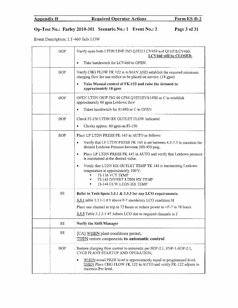
Op-Test No.: Fancy 2010-301 Scenario No.: 1 Event No.: 2 Page 3 of 31
Event Description: LT-460 fails LOW
BOP Verify open both LTDN LINE ISO Q1E21LCV459 and Q1E21LCV46O.LCV46O will be CLOSED.
. Take handswitch for LCV46O to OPEN.
BOP Verify CHG FLOW FK 122 is in MAN establish the required minimumcharging flow for one orifice to be placed on service. (18 gpm)
• Take Manual control of FK-122 and raise the demand toapproximately 18 gpm
BOP OPEN LTDN ORJF ISO 60 GPM Q1E21HV8149B or C to establishapproximately 60 gprn Letdown flow
. Takes handswitch for 8149B or C to OPEN
BOP Check FI-150 LTDN HX OUTLET FLOW indicated
. Checks approx. 60 gpm on FI-150
BOP Place LP LTDN PRESS PK-145 in AUTO as follows:
. Verify that LP LTDN PRESS PK 145 is set between 4.3-7.5 to maintain thedesired Letdown Pressure between 260-450 psig.
. Place LP LTDN PRESS PK 145 in AUTO and verify that Letdown pressureis maintained at the desired value.
. Verify that LTDN HX OUTLET TEMP TK 144 is maintaining Letdowntemperature at approximately 100°F.
• TI-116VCTTEMP• TI-143 DIVERT LTDN HX TEMPw TI-l44 CCW LTDN HX TEMP
SS Refer to Tech Specs 3.3.1 & 3.3.3 for any LCO requirements.
3! table 3.3.1-1 #9 above P-7 mandatory LCO condition M
Place one channel in trip in 72 hours or reduce power to <P-7 in 78 hours
Table 3.3.3-1 #7 Admin LCO due to required channels is 2
SS Notify the Shift Manager
SS [CA] WHEN plant conditions permit,
THEN restore components to automatic control
BOP Restore charging flow control to automatic per SOP-2.1, FNP-l-SOP-2.l,CVCS PLANT STARTUP AND OPERATION,
. WHEN actual PRZR level is approximately equal to programmed level,THEN Place CHG FLOW FK 122 in AUTO and verify FK-122 adjusts tomaintain Pzr level.
Appendix D Required Operator Actions Form ES-D-2
Op-Test No.: Farley 2010-301 Scenario No.: 1 Event No.: 2 Page 3 of 31
Event Description: LT -460 fails LOW
BOP Verify open both LTDN LINE ISO Q1E21LCV459 and Q1E21LCV460. LCV 460 will be CLOSED.
• Take handswitch for LCV460 to OPEN.
BOP Verify CHG FLOW FK 122 is in MAN AND establish the required minimum charging flow for one orifice to be placed on service. (18 gpm)
• Take Manual control ofFK-122 and raise the demand to approximately 18 gpm
BOP OPEN LTDN ORIF ISO 60 GPM Q1E2IHV8149B or C to establish approximately 60 gpm Letdown flow
• Takes handswitch for 8149B or C to OPEN
BOP Check FI-150 LTDN HX OUTLET FLOW indicated
• Checks approx. 60 gpm on FI-150
BOP Place LP LTDN PRESS PK-145 in AUTO as follows:
• Verify that LP LTDN PRESS PK 145 is set between 4.3-7.5 to maintain the desired Letdown Pressure between 260-450 psig.
• Place LP LTDN PRESS PK 145 in AUTO and verify that Letdown pressure is maintained at the desired value.
• Verify that LTDN HX OUTLET TEMP TK 144 is maintaining Letdown temperature at approximately 100°F.
• TI-116 VCT TEMP • TI-143 DIVERT LTDN HX TEMP • TI-144 CCW LTDN HX TEMP
SS Refer to Tech Specs 3.3.1 & 3.3.3 for any LCO requirements.
3.3.1 table 3.3.1-1 # 9 above P-7mandatory LCO condition M
Place one channel in trip in 72 hours or reduce power to <P-7 in 78 hours
3.3.3 Table 3.3.3-1 #7 Admin LCO due to required channels is 2
SS Notify the Shift Manager
SS [CA] WHEN plant conditions permit,
THEN restore components to automatic control
BOP Restore charging flow control to automatic per SOP-2.1, FNP-1-S0P-2.1, CVCS PLANT STARTUP AND OPERATION,
• WHEN actual PRZR level is approximately equal to programmed level, THEN Place CHG FLOW FK 122 in AUTO and verify FK-122 adjusts to maintain Pzr level.

Appendix D Required Operator Actions Form ES-D-2
Op-Test No.: Fancy 2010-301 Scenario No.: 1 Event No.: 2 Page 4 of 31
Event Description: LT-460 fails LOW
BOP Restore control of pressurizer heaters.
. Place 1C PRZR HTR GROUP VARIABLE in ON.
. Ensure 1A, 1B, 1D, 1E PRZR HTR GROUP BACKUP in ON or AUTO.
SS Submit a Condition Report for the failed level channel, and notify theWork Week Coordinator (Maintenance ATL on backshifts) of theCondition Report.
End Event #2
Appendix D Required Operator Actions Form ES-D-2
Op-Test No.: Farley 2010-301 Scenario No.: 1 Event No.: 2 Page 4 of31
Event Description: LT -460 fails LOW
BOP Restore control of pressurizer heaters.
• Place 1 C PRZR HTR GROUP V ARlABLE in ON .
• Ensure lA, lB, lD, IE PRZR HTR GROUP BACKUP in ON or AUTO .
SS Submit a Condition Report for the failed level channel, and notify the Work Week Coordinator (Maintenance ATL on backshifts) of the Condition Report.
End Event #2

Appendix D Required Operator Actions Form ES-D-2
Op-Test No.: Farley 2010-3 01 Scenario No.: 1 Event No.: 3 Page 5 of 31
Event Description: PT-508, Feedwater header pressure, fails high
Cue: By Examiner.
Time Position Applicant’s Action or Behavior
Annunciators: Recognize indications of PT-508 failure
o lA,1B,OR 1C SG LVL DEV (JF1, JF2, - SGFP speed decreasingJF3)
- FRVs openingo 1A,1B,OR 1C SG STM FLOW> FEED
FLOW (JB 1, JB2 JB3)- SGWL NR decreasing
- Feed flows decrease to zero
In this event PT-508 fails high. SGFP speed will decrease and the FRVs will start to go full open.
AOP- 100 section 1.4 will be entered.
Immediate operator action
BOP Check that steam and feed flows matched on all SGs NO
. Take manual control of SK-509A and decrease SGFP speed
. Possibly take manual control of all FRVs
o lA SG FW FLOW FK-478
o lB SG FW FLOW FK-488
o lC SG FW FLOW FK-498
SS IF adverse trend in SG level exists, THEN establish trip criteria.
BOP • Place the Main Turbine on HOLD
• Unit I NO LOAD zP is 50 psid from 0-28.1%. PROGRAM AP is linear from 50-190 psid from28.1% to 100%. TABLE-l provides approximate tP values for varying power levels.
BOP Adjust SGFP speed back to within the normal operating range for the feedflow/steam flow AP required for the existing power level
Appendix D Required Operator Actions Form ES-D-2
Op-Test No.: Farley 2010-301 Scenario No.: 1 Event No.: 3 Page 5 of 31
Event Description: PT-508, Feedwater header pressure, fails high
r<. n r. "'-'u".
'T': Position Applicant's Action or Behavior ~ .....
Annunciators: Recognize indications ofPT-508 failure
0 lA,lB,OR Ie SG LVL DEV (JFl, JF2, - SGFP speed decreasing JF3 )
- FR V s opening 0 lA,lB,OR Ie SG STM FLOW> FEED
SGWL NR decreasing FLOW (JBl, JB2 JB3) -
- Feed flows decrease to zero
In this event PT-508 fails high. SGFP speed will decrease and the FRVs will start to go full open.
AOP-I00 section 1.4 will be entered.
Immediate oQerator action
BOP Check that steam and feed flows matched on all SGs NO
• Take manual control of SK-509A and decrease SGFP speed
• Possibly take manual control of all FRV s
0 lA SG FW FLOW FK-478
0 lB SG FW FLOW FK-488
0 Ie SG FW FLOW FK-498
SS IF adverse trend in SG level exists, THEN establish trip criteria.
BOP • Place the Main Turbine on HOLD
• Unit 1 NO LOAD t.P is 50 psid from 0-28.1 %. PROGRAM t.P is linear from 50-190 psid from 28.1 % to 100%. TABLE-l provides approximate t.P values for varying power levels.
BOP Adjust SGFP speed back to within the normal operating range for the feed flow/steam flow t.P required for the existing power level

Appendix D Required Operator Actions Form ES-D-2
Op-Test No.: Farley 2010-301 Scenario No.: 1 Event No.: 3 Page 6 of 31
Event Description: PT-508, Feedwater header pressure, fails high
BOP Approximate AP can be determined from the following MCB indications
o SGFP DISCH PRESS P14003
o SG Pressure indications:
S/G CHIT CH III CH IV
A S/G P1-474 P1-475 P1-476
B S/G P1-484 P1-485 P1-486
C S/G P1-494 P1-495 P1-496
At this power level DP should be approx. 135 psid
SS Call Shift Manager.
Submit a condition report on the failed instrument, and notify the Work WeekCoordinator (Maintenance ATL on backshifts) of the condition report
SS Submit a Condition Report for the failed level channel, and notify theWork Week Coordinator (Maintenance ATL on backshifts) of theCondition Report.
END — Event 3
Appendix D Required Operator Actions Form ES-D-2
Op-Test No.: Farley 2010-301 Scenario No.: 1 Event No.: 3 Page 6 of 31
Event Description: PT -508, Feedwater header pressure, fails high
BOP Approximate llP can be determined from the following MCB indications
0 SGFP DISCH PRESS PI4003
0 SG Pressure indications:
S/G CH II CH III CHIV
AS/G PI-474 PI-475 PI-476
B S/G PI-484 PI-485 PI-486
C S/G PI-494 PI-495 PI-496
At this power level DP should be approx. 135 psid
SS Call Shift Manager.
Submit a condition report on the failed instrument, and notify the Work Week Coordinator (Maintenance A TL on backshifts) of the condition report
SS Submit a Condition Report for the failed level channel, and notify the Work Week Coordinator (Maintenance ATL on backshifts) of the Condition Report.
END Event 3

Appendix D Required Operator Actions Form ES-D-2
Op-Test No.: Farley 2010-301 Scenario No.: 1 Event No.: 4 Page 7 of 31
Event Description: Running Charging Pump experiences a shaft shear
Cue: By Exanner.
Time Position Applicant’s Action or Behavior
Annunciators: Recognize indications of sheared shaft
CHG HDR FLOW HI-LO (EA2) - FI-122A decreasing toO gpm
RCP SEAL INJ FLOW LO (DD1) - 1A Chg pump amps decrease to —SO amps
REGEN HX LTDN FLOW DISCH TEMP HI - SI flow decreases toO gpm on all 3 RCPs(DEl) - possible
- VCT level rising
- PRZR level decreasing
AOP-16 entry required
SS Direct entry into the ARP, then direct entry to AOP-16.O, CVCSMALFUNCTION
BOP Stop any load change in progress
. Places main turbine on HOLD.
RO Monitor VCT level to ensure proper level is maintained.
RO Observe CHG HDR PRESS and MOTOR AMPS to ensure propercharging pump operation. (SOER 97-1)
. P1-121 reads approx 2050 psig
. AMMETER FOR RU1NING CHG PUMP approx 0 amps
RO Check charging pump - RUNNING. NO
RO Start an available charging pump as follows:. Check VCT level and pressure adequate.
ChecksPl-1l7 andLIll5/112. Verify charging suction flowpath aligned
VCT OUTLET ISO valves - OPEN YESQ1E21LCV1 15CQ1E21LCV1 15E
ORRWST TO CHG PUMP valves - OPEN
Q1E21LCV1 15BQ1E21LCV1 15D
RO Check auxiliary oil pump running for charging pump to be started as indicatedby white light illuminated on MCB.
Appendix D Required Operator Actions Form ES-D-2
Op-Test No.: Farley 2010-301 Scenario No.: 1 Event No.: 4 Page 7 of31
Event Description: Running Charging Pump experiences a shaft shear
~. er. -Time Position Applicant's Action or Behavior
Annunciators: Recognize indications of sheared shaft
- CHG HDR FLOW HI-LO (EA2) - FI-122A decreasing to 0 gpm
- RCP SEAL INJ FLOW LO (DDI) - IA Chg pump amps decrease to -0 amps
- REGEN HX LTDN FLOW DISCH TEMP HI - SI flow decreases to 0 gpm on all 3 RCPs (DEI) - possible
- VCT level rising
- PRZR level decreasing
AOP-16 entry required
SS Direct entry into the ARP, then direct entry to AOP-16.0, CVCS MALFUNCTION
BOP Stop any load change in progress
• Places main turbine on HOLD.
RO Monitor VCT level to ensure proper level is maintained.
RO Observe CRG RDR PRESS and MOTOR AMPS to ensure proper charging pump operation. (SOER 97-1)
• PI-121 reads approx 2050 psig
• AMMETER FOR RUNNING CHG PUMP approx 0 amps
RO Check charging pump - RUNNING. NO
RO Start an available charging pump as follows:
• Check VCT level and pressure adequate. Checks PI-117 and LI1151112
• Verify charging suction flowpath aligned VCT OUTLET ISO valves - OPEN YES
QIE2lLCV115C QIE2lLCV115E
OR RWST TO CHG PUMP valves - OPEN
QIE21LCVl15B QIE21LCV115D
RO Check auxiliary oil pump running for charging pump to be started as indicated by white light illuminated on MCB.

Appendix D Required Operator Actions Form ES-D-2
Op-Test No.: Farley 2010-301 Scenario No.: 1 Event No.: 4 Page 8 of 31
Event Description: Running Charging Pump experiences a shaft shear
RO Check open miniflow isolation for charging pump to be started — 8109B and Cand 8106 OPEN
RO Close SEAL WTR INJECTION HIK 186
RO Verify a CCW pump is running in same train aligned to supply charging pumpto be started.
. Verifies 1 A CCW pump is running
RO Start 1 C charging pump.
RO Observe CHG HDR PRESS indicator P1 121 and motor ammeter to checkproper pump operation
RO WHEN charging pump comes up to speed, THEN check auxiliary oil pumpstops as indicated by white light QI being illuminated on MCB.
RO Adjust SEAL WTR INJECTION HIK 186 to maintain 6-13 gpm seal injectionflow to each RCP.
RO Check Charging flow FK-122 controlling in AUTO with flow indicated.
RO Check the following annunciator — CLEAR
DE3 LTDN ORIF ISO VLV REL LINE TEMP HI YES
If NO then the RNO is to check PRT parameters stable
Then take letdown off service if deemed excessive. Should be NO
There is a procedural issue in that PK- 145 is not placed in manual and run to50%. If this is not done by the candidate, then DE3 may come into alarm due toPCV-145 not responding fast enough. The relief will lift momentarily and thenclose as proven by the temperature reading.
RO Determine Status of Normal Letdown IN SERVICE
SS Go to step 17 and Determine Charging Status No longer affected
If the SS determines charging is affected then they will continue to step 25after checking charging flow path and przr level and letdown.
TEAM Refers to ARPs as appropriate to verify all actions completed:
• ARP-1.5 (EA2) Charging Header Flow Hi-Lo
SS Initiated actions to have the lB Charging Pump moved to A train
Team Procedure does not require opening 1A CHG pump BKR but team may open itand rack it out since it is not operable.
Appendix D Required Operator Actions Form ES-D-2
Op-Test No.: Farley 2010-301 Scenario No.: 1 Event No.: 4 Page 8 of31
Event Description: Running Charging Pump experiences a shaft shear
RO Check open mini flow isolation for charging pump to be started - 8109B and C and 8106 OPEN
RO Close SEAL WTR INJECTION HIK 186
RO Verify a CCW pump is running in same train aligned to supply charging pump to be started.
• Verifies 1A CCW pump is running
RO Start 1 C charging pump.
RO Observe CHG HDR PRESS indicator PI 121 and motor ammeter to check proper pump operation
RO WHEN charging pump comes up to speed, THEN check auxiliary oil pump stops as indicated by white light NOT being illuminated on MCB.
RO Adjust SEAL WTR INJECTION HIK 186 to maintain 6-13 gpm seal injection flow to each RCP.
RO Check Charging flow FK-122 controlling in AUTO with flow indicated.
RO Check the following annunciator - CLEAR
DE3 LTDN ORIF ISO VLV REL LINE TEMP HI YES
If NO then the RNO is to check PRT parameters stable
Then take letdown off service if deemed excessive. Should be NO
There is a procedural issue in that PK-145 is not placed in manual and run to 50%. If this is not done by the candidate, then DE3 may come into alarm due to PCV -145 not responding fast enough. The relief will lift momentarily and then close as proven by the temperature reading.
RO Determine Status of Normal Letdown IN SERVICE
SS Go to step 17 and Determine Charging Status No longer affected
If the SS determines charging is affected then they will continue to step 25 after checking charging flow path and przr level and letdown.
TEAM Refers to ARPs as appropriate to verify all actions completed:
• ARP-1.5 (EA2) Charging Header Flow Hi-Lo
SS Initiated actions to have the 1B Charging Pump moved to A train
Team Procedure does not require opening 1A CHG pump BKR but team may open it and rack it out since it is not operable.

Appendix B Reciuired Operator Actions Form ES-B-2
Op-Test No.: Farley 2010-301 Scenario No.: 1 Event No.: 4 Page 9 of 31
Event Description: Running Charging Pump experiences a shaft shear
SS RCS pressure may drop below 2209 psig and TS 3.4.1 mandatory LCOcondition A entered to restore RCS pressure to >2209 in 2 hours.
. This drops slowly over 5 minutes to <2209 and may not beencountered by a faster moving crew.
SS Refer to Technical Specifications LCOs 3.5.2, and Technical Requirements TR13.1.5.
. 3.5.2 Mandatory LCO Condition A; since the lB chg pump is aligned to BTrain and the damaged pump is an A Train pump. 72 hour LCO until thelB chg pump is placed on A Train and the 1A CHG pump is either rackedout or has a jumper installed to allow 1 B chg pump to auto start.
. 13.1.5 Admin LCO Condition A. Two charging pumps shall be operable.72 hour LCO
SS Write CR and contact SM / WWC / ATL for repair
End event 4
Appendix D Required Operator Actions Form ES-D-2
Op-Test No.: Farley 2010-301 Scenario No.: 1 Event No.: 4 Page 9 of 31
Event Description: Running Charging Pump experiences a shaft shear
SS RCS pressure may drop below 2209 psig and TS 3.4.1 mandatory LCO condition A entered to restore RCS pressure to >2209 in 2 hours.
• This drops slowly over 5 minutes to <2209 and may not be encountered by a faster moving crew.
SS Refer to Technical Specifications LCOs 3.5.2, and Technical Requirements TR 13.1.5.
• 3.5.2 Mandatory LCO Condition A; since the 1B chg pump is aligned to B Train and the damaged pump is an A Train pump. 72 hour LCO until the 1B chg pump is placed on A Train and the 1A CRG pump is either racked out or has a jumper installed to allow 1B chg pump to auto start.
• 13 .1.5 Admin LCO Condition A. Two charging pumps shall be operable . 72 hour LCO
SS Write CR and contact SM / WWC / ATL for repair
End event 4
Appendix D Required Operator Actions Form ES-D-2
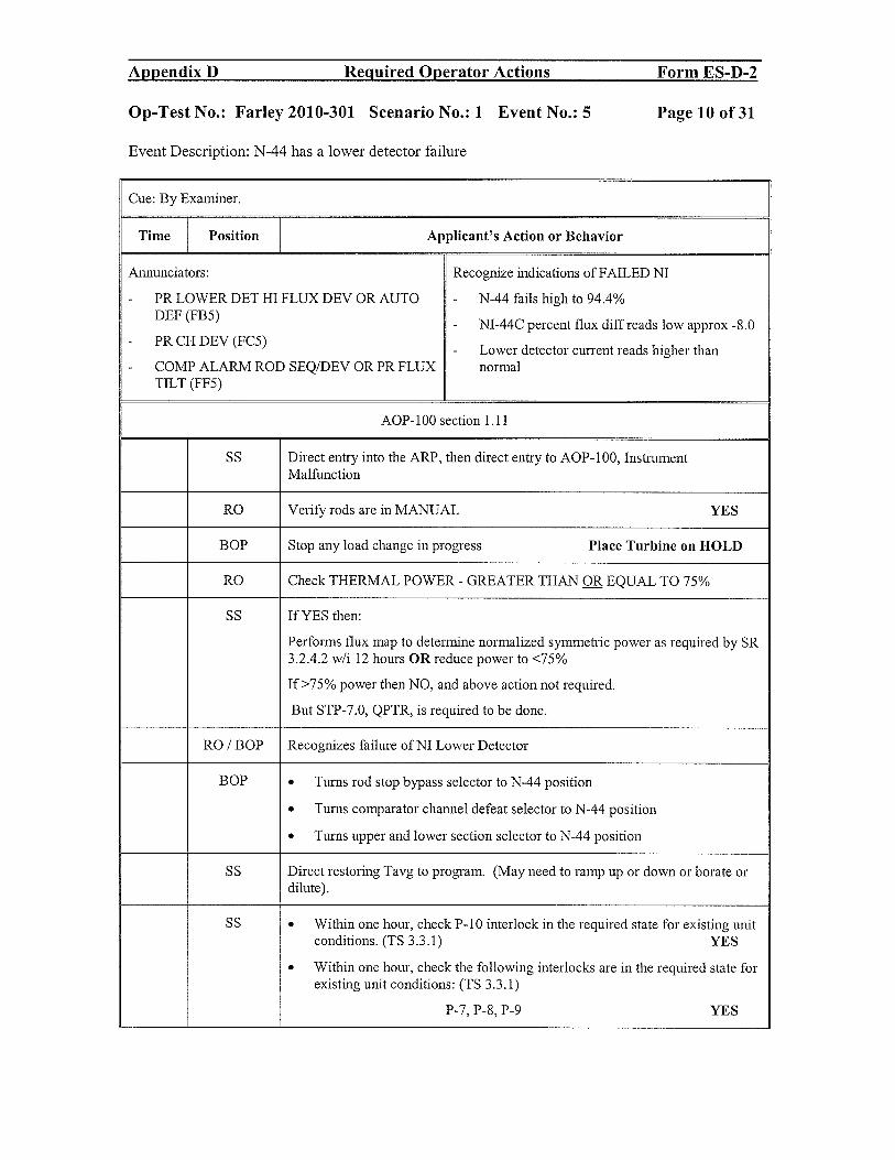
Op-Test No.: Farley 2010-301 Scenario No.: 1 Event No.: 5 Page 10 of 31
Event Description: N-44 has a lower detector failure
Cue: By Examiner.
Time Position Applicant’s Action or Behavior
Annunciators: Recognize indications of FAILED NI
PR LOWER DET HI FLUX DEV OR AUTO N-44 fails high to 94.4%DEF(FB5)
- NI-44C percent flux diff reads low approx -8.0PR CH DEV (FC5)
- Lower detector current reads higher thanCOMP ALARM ROD SEQIDEV OR PR FLUX normalTILT (FF5)
AOP-100 section 1.11
SS Direct entry into the ARP, then direct entry to AOP- 100, InstrumentMalfunction
RO Verify rods are in MANUAL YES
BOP Stop any load change in progress Place Turbine on HOLD
RO Check THERMAL POWER - GREATER THAN OR EQUAL TO 75%
SS If YES then:
Performs flux map to determine normalized symmetric power as required by SR3.2.4.2 w/i 12 hours OR reduce power to <75%
If >75% power then NO, and above action not required.
But STP-7.0, QPTR, is required to be done.
RO / BOP Recognizes failure of NI Lower Detector
BOP • Turns rod stop bypass selector to N-44 position
• Turns comparator channel defeat selector to N-44 position
• Turns upper and lower section selector to N-44 position
SS Direct restoring Tavg to program. (May need to ramp up or down or borate ordilute).
SS • Within one hour, check P-10 interlock in the required state for existing unitconditions. (TS 3.3.1) YES
• Within one hour, check the following interlocks are in the required state forexisting unit conditions: (TS 3.3.1)
P-7, P-8, P-9 YES
Appendix D Required Operator Actions Form ES-D-2
Op-Test No.: Farley 2010-301 Scenario No.: 1 Event No.: 5 Page 10 of 31
Event Description: N-44 has a lower detector failure
Cue: By Examiner.
Time Position Applicant's Action or Behavior
Almunciators: Recognize indications of FAILED NI
- PR LOWER DET HI FLUX DEV OR AUTO - N-44 fails high to 94.4% DEF (FB5) - NI-44C percent flux diffreads low approx -S.o
- PR CH DEV (FC5) Lower detector current reads higher than -
- COMP ALARM ROD SEQ/DEV OR PR FLUX normal TILT (FF5)
AOP-100 section 1.11
SS Direct entry into the ARP, then direct entry to AOP-1 00, Instrument Malfunction
RO Verify rods are in MANUAL YES
BOP Stop any load change in progress Place Turbine on HOLD
RO Check THERMAL POWER - GREATER THAN OR EQUAL TO 75%
SS If YES then:
Performs flux map to determine normalized symmetric power as required by SR 3.2.4.2 w/i 12 hours OR reduce power to <75%
If>75% power then NO, and above action not required.
But STP-7.0, QPTR, is required to be done.
RO/BOP Recognizes failure ofNI Lower Detector
BOP • Turns rod stop bypass selector to N-44 position
• Turns comparator channel defeat selector to N-44 position
• Turns upper and lower section selector to N-44 position
SS Direct restoring Tavg to program. (May need to ramp up or down or borate or dilute).
SS • Within one hour, check P-10 interlock in the required state for existing unit conditions. (TS 3.3.1) YES
• Within one hour, check the following interlocks are in the required state for existing unit conditions: (TS 3.3.1)
P-7, P-S, P-9 YES

Appendix D Required Operator Actions Form ES-D-2
Op-Test No.: Farley 2010-301 Scenario No.: 1 Event No.: 5 Page 11 of 31
Event Description: N-44 has a lower detector failure
BOP Trip bistables for N-44 by pulling the control power fuses from the A drawer
SS Notify the Shift Manager.
SS Refers to Tech Specs 3.3.1 for LCO requirements
Table 3.3.1-1 Function 2a, 3, 6 AND 17 c, d, e
• 3.3.1.D — Place N-44 in trip w/i 72 hours and reduce power to < 75%RTP in 78 hours OR Place N-44 in trip w/i 72 hours and do a QPTROR be in MODE 3 in 78 hours
. 3.3.1.E — Admin - Place N-44 in trip w/i 72 hours OR be in MODE 3in 78 hours
• 3.3.l.T - Verify interlock is in required state for existing unitconditions w/i 1 hour or be in MODE 3 in 7 hours
. 3.3.1 U — Verify interlock is in required state for existing unitconditions w/i 1 hour or be in MODE 2 in 7 hours
SS Writes CR and contacts SM / WWC / ATL for repair
END — Event 5
Appendix D Required Operator Actions Form ES-D-2
Op-Test No.: Farley 2010-301 Scenario No.: 1 Event No.: 5 Page 11 of31
Event Description: N-44 has a lower detector failure
BOP Trip bistables for N-44 by pulling the control power fuses from the A drawer
SS Notify the Shift Manager.
SS Refers to Tech Specs 3.3.1 for LCO requirements
Table 3.3.1-1 Function 2a, 3, 6 AND 17 c, d, e
• 3.3.1.D - Place N-44 in trip w/i 72 hours and reduce power to :s 75% RTP in 78 hours OR Place N-44 in trip w/i 72 hours and do a QPTR OR be in MODE 3 in 78 hours
• 3.3.1.E - Admin - Place N-44 in trip wli 72 hours OR be in MODE 3 in 78 hours
• 3.3.1. T - Verify interlock is in required state for existing unit conditions wli 1 hour or be in MODE 3 in 7 hours
• 3.3.1 U - Verify interlock is in required state for existing unit conditions wli 1 hour or be in MODE 2 in 7 hours
SS Writes CR and contacts SM / WWC / ATL for repair
END - Event 5

Appendix D Required Operator Actions Form ES-D-2
Op-Test No.: Farley 2010-301 Scenario No.: 1 Event No.: 6 & 7 Page 12 of 31
Event Description:#6 Reactor fails to trip and Loss of off site power occurs when the reactor is tripped by MG setsupply breakers having to be opened. 1 -2A EDG does not auto start and cannot be manuallystarted.# 7 When PORV lifts it fails to close fully and block valve fails in mid position when closed.
Cue: By Examiner.
Explanation on sequence of Events: ‘A’ Train ESF BUS will trip. This will trigger a spurious TurbineTrip and give numerous first out annunciators and TSLB bistables requiring a Reactor Trip with AutoReactor Trips blocked, crew will have to recognize need for a reactor trip and manually trip the reactor.Trip will only be accomplished when one MG set supply breaker is opened. Steam dumps will fail tooperate resulting in PORV lift and malfunction of the appropriate valves. Once the Reactor Trips this willtrigger a complete LOSP with the lB EDG starting and energizing the B train ESF buses. With the PORVand BLOCK Valve stuck open, a Safety Injection must be manually activated due to SSPS failures. BTrain Phase A will not occur and will have to be manually actuated.
Time Position Applicant’s Action or Behavior
Annunciators: Recognize indications of Loss of lF BUS and- TURB AUTO STOP OIL TURB TRIP (GH2) subsequent Turbine Trip:- RX TRIP CAUSED BY TURB TRIP (GF4) - Loss of power indication lights to 4160 V buses- Numerous annunciators on the EPB 1 F, 1 K, 1 H
- Main Turbine GVs go closed
NOTE: lB DG will trip on overspeed 10 minutes after RCS press <1850 psi.
When this occurs ECP-0 will be entered. The actions for ECP-0.0 are in tab 1
SS / RO / Recognize Rx Trip Called for but did not occurBOP
SS Directs Manually tripping the reactor and performance of immediate operatoractions Updates crew on EEP-0 entry.
Appendix D Required Operator Actions Form ES-D-2
Op-Test No.: Farley 2010-301 Scenario No.: 1 Event No.: 6 & 7 Page 12 of31
Event Description: #6 Reactor fails to trip and Loss of off site power occurs when the reactor is tripped by MG set supply breakers having to be opened. 1-2A EDG does not auto start and cannot be manually started. # 7 When PORV lifts it fails to close fully and block valve fails in mid position when closed.
Cue: By Examiner.
Explanation on sequence of Events: 'A' Train ESF BUS will trip. This will trigger a spurious Turbine Trip and give numerous first out annunciators and TSLB bistables requiring a Reactor Trip with Auto Reactor Trips blocked, crew will have to recognize need for a reactor trip and manually trip the reactor. Trip will only be accomplished when one MG set supply breaker is opened. Steam dumps will fail to operate resulting in PORV lift and malfunction of the appropriate valves. Once the Reactor Trips this will trigger a complete LOSP with the IB EDG starting and energizing the B train ESF buses. With the PORV and BLOCK Valve stuck open, a Safety Injection must be manually activated due to SSPS failures. B Train Phase A will not occur and will have to be manually actuated.
Time Position Applicant's Action or Behavior
Annunciators: Recognize indications of Loss of IF BUS and - TURB AUTO STOP OIL TURB TRIP (GH2) subsequent Turbine Trip: - RX TRIP CAUSED BY TURB TRIP (GF4) - Loss of power indication lights to 4160 V buses - Numerous annunciators on the EPB IF, lK, 1H
- Main Turbine GVs go closed
NOTE: 1B DG will triu on oversueed 10 minutes after RCS uress <1850 usig.
When this occurs ECP-O will be entered. The actions for ECP-O.O are in tab 1
SS IRO I Recognize Rx Trip Called for but did not occur BOP
SS Directs Manually tripping the reactor and performance of immediate operator actions Updates crew on EEP-O entry.

Appendix D Reguired Operator Actions Form ES-D-2
Op-Test No.: Farley 2010-301 Scenario No.: 1 Event No.: 6 & 7 Page 13 of 31
Event Description:#6 Reactor fails to trip and Loss of off site power occurs when the reactor is tripped by MG setsupply breakers having to be opened. 1 -2A EDG does not auto start and cannot be manuallystarted.# 7 When PORV lifts it fails to close fully and block valve fails in mid position when closed.
RO / BOP Immediate Operator actions of EEP-0
Check reactor trip.Check all reactor trip breakers and reactor tripbypass breakers - OPEN. NO
Critical task
TRIP CRDM MG set supply breakers.(CT) 1A(lB) MG SET SUPP BKR
[]N1C11EOO5A []N1C11EOO5BOpens both MG set supply breakers. Reactor Trips
LOSP OCCURS WHEN RX TRIPS
Check reactor trip.Check nuclear power - FALLING.Check rod bottom lights - LIT. YES
Check turbine - TRIPPED. YESTSLB2 14-1 thru4 lit
Check power to 4160 V ESF busses.4160 V ESF busses - AT LEAST ONE ENERGIZED YES
A Train (F & K) power available lights lit NOORB Train (G & L) power available lights lit YES
Verify operating diesel generators are being supplied from at YESleast one SW pump.
RO / BOP • Check any SI actuated indication
- BYP & PERMISSIVE SAFETY iNJECTION NO[1 ACTUATED status light lit[]MLB-1 1-1 lit
[] MLB—1 11—1 lit
* IF TSLB bistables meet coincidence for SI, THEN SI is required.PRZR PRESS LO 1850 2/3 TSLB2 17-1, 17-2, 17-3SI will be required due to the PORV open and block valve will not close• IF any parameter shown in the Table below has been lit reached or
exceeded, THEN SI is required.
(C 1) Critical task
Initiate SI
Appendix D Required Operator Actions Form ES-D-2
Op-Test No.: Farley 2010-301 Scenario No.: 1 Event No.: 6 & 7 Page 13 of31
Event Description: #6 Reactor fails to trip and Loss of off site power occurs when the reactor is tripped by MG set supply breakers having to be opened. 1-2A EDG does not auto start and cannot be manually started. # 7 When PORV lifts it fails to close fully and block valve fails in mid position when closed.
RO/BOP Immediate Operator actions ofEEP-O
Check reactor trip. Check all reactor trip breakers and reactor trip bypass breakers - OPEN. NO
Critical task
TRIP CRDM MG set supply breakers. (CT) 1A(lB) MG SET SUPP BKR
[] N1 C11E005A [] N1C1IE005B Opens both MG set supply breakers. Reactor Trips
LOSP OCCURS WHEN RX TRIPS
Check reactor trip. Check nuclear power - FALLING. Check rod bottom lights - LIT. YES
Check turbine - TRIPPED. YES TSLB2 14-1 thru 4 lit
Check power to 4160 V ESF busses. 4160 V ESF busses - AT LEAST ONE ENERGIZED YES
A Train (F & K) power available lights lit NO OR B Train (G & L) power available lights lit YES
Verify operating diesel generators are being supplied from at YES least one SW pump.
RO/BOP • Check any SI actuated indication
- BYP & PERMISSIVE SAFETY INJECTION NO [] ACTUATED status light lit [] MLB-1 1-1 lit [] MLB-1 11-1 lit
* IF TSLB bistables meet coincidence for SI, THEN SI is required. PRZRPRESS LO 1850213 TSLB2 17-1, 17-2, 17-3 SI will be reguired due to the PORV oQen and block valve will not close
• IF any parameter shown in the Table below has been lit reached or exceeded, THEN SI is required.
(Cl') Critical task
Initiate SI

Appendix B Required Operator Actions Form ES-B-2
Op-Test No.: Farley 2010-301 Scenario No.: 1 Event No.: 6 & 7 Page 14 of 31
Event Description:#6 Reactor fails to trip and Loss of off site power occurs when the reactor is tripped by MG setsupply breakers having to be opened. 1 -2A EDG does not auto start and cannot be manuallystarted.# 7 When PORV lifts it fails to close fully and block valve fails in mid position when closed.
RO / BOP • Should notice PORV-444B not closed and attempt to close Valve will notclose
. Should close PORV Block Valve 8000B. (8000B will stick at 50% open)
RO • Recognize that RCS pressure is less than 1300 psig and Foldout pagerequirements to close miniflows
• MOV81O9A, B, C and 8106 CLOSED
SS Directs continuing into EEP-0 at step 5.
Directs the BOP to do Attachment 2.
BOP Verifies actuation signal automatic actions using ATTACHMENT 2,AUTOMATIC ACTIONS VERIFICATION.
See Tab at end of scenario Attachment 2 and 4 for actions
SS / RO [CA] Check containment pressure- HASREMAINED LESS THAN 27 psig YESCTMT PRESS
[] PR950
SS / RO Announce “Unit 1 reactor trip and safety injection”.
Appendix D Required Operator Actions Form ES-D-2
Op-Test No.: Farley 2010-301 Scenario No.: 1 Event No.: 6 & 7 Page 14 of 31
Event Description: #6 Reactor fails to trip and Loss of off site power occurs when the reactor is tripped by MG set supply breakers having to be opened. 1-2A EDG does not auto start and cannot be manually started. # 7 When PORV lifts it fails to close fully and block valve fails in mid position when closed.
RO/BOP • Should notice PORV-444B not closed and attempt to close Valve will not close
• Should close PORV Block Valve 8000B. (8000B will stick at 50% open)
RO • Recognize that RCS pressure is less than 1300 psig and Foldout page requirements to close miniflows
• MOV8109A, B, C and 8106 CLOSED
SS Directs continuing into EEP-O at step 5.
Directs the BOP to do Attachment 2.
BOP Verifies actuation signal automatic actions using ATTACHMENT 2, AUTOMATIC ACTIONS VERIFICATION.
See Tab at end of scenario Attachment 2 and 4 for actions
SS/RO [CAl Check containment pressure- HAS REMAINED LESS THAN 27 psig YES CTMTPRESS [] PR 950
SS/RO Announce "Unit 1 reactor trip and safety injection".

Appendix B Required Operator Actions Form ES-D-2
Op-Test No.: Farley 20 10-301 Scenario No.: 1 Event No.: 6 & 7 Page 15 of 31
Event Description:#6 Reactor fails to trip and Loss of off site power occurs when the reactor is tripped by MG setsupply breakers having to be opened. 1 -2A EDG does not auto start and cannot be manuallystarted.# 7 When PORV lifts it fails to close fully and block valve fails in mid position when closed.
SS / RO Check AFW status.Check secondary heat sink Available
o Check total AFW flow> 395 gpm[]FI 3229A[]FI 3229B[]FI 3229C
o Total Flow Fl 3229OR
o CheckanySGNRlevel>31% {48%}
o WHEN all SC narrow range levels less than 31%{48%},THEN maintain total AFW flow greater than 395 gpm.
o WHEN at least two SG narrow range levels greater than 28%AND TDAFWP NOT required, THEN stop TDAFWP.
[CA] WHEN SG narrow range level greater than 31% {48%},THEN maintain SG narrow range level 31%-65%{48%-65%}.
o Control MDAFWP flow.MDAFWP FCV 3227 RESET
[j A TRN reset[] B TRN resetMDAFWP TO lA/lB/iC SC B TRN[]FCV 3227 in MOD
o Control TDAFWP flow.TDAFWP FCV 3228
[] RESET resetTDAFWP SPEED CONT[]SIC 3405 adjusted
Appendix D Required Operator Actions Form ES-D-2
Op-Test No.: Farley 2010-301 Scenario No.: 1 Event No.: 6 & 7 Page 15 of 31
Event Description: #6 Reactor fails to trip and Loss of off site power occurs when the reactor is tripped by MG set supply breakers having to be opened. 1-2A EDG does not auto start and cannot be manually started. # 7 When PORV lifts it fails to close fully and block valve fails in mid position when closed.
SSIRO Check AFW status. Check secondary heat sink Available
0 Check total AFW flow> 395 gpm [] FI 3229A [] FI 3229B [] FI 3229C
0 Total Flow FI 3229 OR
0 Check any SO NR level> 31 % {48%}
0 WHEN all SO narrow range levels less than 31 % {48%}, THEN maintain total AFW flow greater than 395 gpm.
0 WHEN at least two SO narrow range levels greater than 28% AND TDAFWP NOT required, THEN stop TDAFWP.
[CA] WHEN SO narrow range level greater than 31 %{48%}, THEN maintain SO narrow range level 31 %-65% {48%-65%}.
0 Control MDAFWP flow. MDAFWP FCV 3227 RESET [] A TRN reset [] B TRN reset MDAFWP TO lA/lB/1C SO B TRN [] FCV 3227 in MOD
0 Control TDAFWP flow. TDAFWP FCV 3228 [] RESET reset TDAFWP SPEED CONT [] SIC 3405 adjusted

Appendix D Required Operator Actions Form ES-D-2
Op-Test No.: Farley 2010-301 Scenario No.: 1 Event No.: 6 & 7 Page 16 of 31
Event Description:#6 Reactor fails to trip and Loss of off site power occurs when the reactor is tripped by MG setsupply breakers having to be opened. l-2A EDG does not auto start and cannot be manuallystarted.# 7 When PORV lifts it fails to close fully and block valve fails in mid position when closed.
SS/ROCheck RCS temperature.IF any RCP running, THEN check RCS average temperature - STABLE AT ORAPPROACHING 547°F.TAVG 1A(1B,1C) RCS LOOP[]TI 412D[]TI 422D[jTI432D
RNOIF RCS temperature less than 547°F and falling, THEN perform the following.Verify steam dumps closed,STM DUMP INTERLOCK[IA TRN in OFF RESET[lB TRN in OFF RESET
Verify atmospheric relief’s closed on MCB Demand at 0 andminimum red light LIT
Control total AFW flow to minimize RCS cooldown,AFW FLOW TO 1A(1B,1C) SG[]FI 3229A
[j Fl 3229B[J Fl 3229CAFW TOTAL FLOW[]FI 3229
Isolate steam loads in the turbine buildingCall TBSO to isolate steam loads
IF cooldown continues, THEN close MSIVs and MSIV bypass valves.Cooldown will be controlled
Appendix D Required Operator Actions Form ES-D-2
Op-Test No.: Farley 2010-301 Scenario No.: 1 Event No.: 6 & 7 Page 16 of 31
Event Description: #6 Reactor fails to trip and Loss of off site power occurs when the reactor is tripped by MG set supply breakers having to be opened. 1-2A EDG does not auto start and cannot be manually started. # 7 When PORV lifts it fails to close fully and block valve fails in mid position when closed.
SS/RO Check RCS temperature. IF any RCP running, THEN check RCS average temperature - STABLE AT OR APPROACHING 547°F. TAVG lA(lB,lC) RCS LOOP [] TI 412D [] TI 422D [] TI 432D
RNO IF RCS temperature less than 547°F and falling, THEN perform the following. Verify steam dumps closed. STM DUMP INTERLOCK [] A TRN in OFF RESET [] B TRN in OFF RESET
Verify atmospheric reliefs closed on MCB Demand at 0 and minimum red light LIT
Control total AFW flow to minimize RCS cooldown, AFW FLOW TO lA(lB,lC) SG [] FI 3229A [] FI 3229B [] FI 3229C AFW TOTAL FLOW [] FI 3229
Isolate steam loads in the turbine building Call TBSO to isolate steam loads
IF cooldown continues, THEN close MSIVs and MSIV bypass valves. Cooldown will be controlled

Appendix P Required Operator Actions Form ES-D-2
Op-Test No.: Farley 2010-301 Scenario No.: 1 Event No.: 6 & 7 Page 17 of 31
Event Description:#6 Reactor fails to trip and Loss of off site power occurs when the reactor is tripped by MG setsupply breakers having to be opened. 1 -2A EDG does not auto start and cannot be manuallystarted.# 7 When PORV lifts it fails to close fully and block valve fails in mid position when closed.
/ ROCheck pressurizer PORVs and spray valves.
WHEN pressurizer pressure less than 2335 psig, THEN verify both PRZRPORV’s closed.
Verify both PRZR PORV’s indicate CLOSED NO
NOTE: PROV 444B and associated Block Valve MOV8000B will both bestuck open. This will Require the SS to Transition TO EEP-1.
RNO
IF any PORV can NOT be closed, THEN close associated PRZRPORV ISO.IF open PRZR PORV NOT isolated or PRZR SAFETY valve stuck open,THEN go to FNP-1-EEP-1, LOSS OF REACTOR OR SECONDARYCOOLANT.
NOTE: lB DG will trip on overspeed 10 minutes after RCS press <1850psig. Trigger 1
Updates Crew on Transition Requirement to EEP-1
AppendixD Required Operator Actions Form ES-D-2
Op-Test No.: Farley 2010-301 Scenario No.: 1 Event No.: 6 & 7 Page 17 of31
Event Description: #6 Reactor fails to trip and Loss of off site power occurs when the reactor is tripped by MG set supply breakers having to be opened. 1-2A EDG does not auto start and cannot be manually started. # 7 When PORV lifts it fails to close fully and block valve fails in mid position when closed.
SS/RO
SS
Check pressurizer PORVs and spray valves.
WHEN pressurizer pressure less than 2335 psig, THEN verify both PRZR PORV's closed.
Verify both PRZR PORV's indicate CLOSED NO
NOTE: PROV 444B and associated Block Valve MOV8000B will both be stuck open. This will Require the SS to Transition TO EEP-l.
RNO
IF any PORV can NOT be closed, THEN close associated PRZR PORV ISO. IF open PRZR PORV NOT isolated or PRZR SAFETY valve stuck open, THEN go to FNP-1-EEP-1, LOSS OF REACTOR OR SECONDARY COOLANT.
NOTE: IB DG will trip on overspeed 10 minutes after RCS press <1850 psig. Trigger 1
Updates Crew on Transition Requirement to EEP-l
Appendix D Required Operator Actions Form ES-D-2
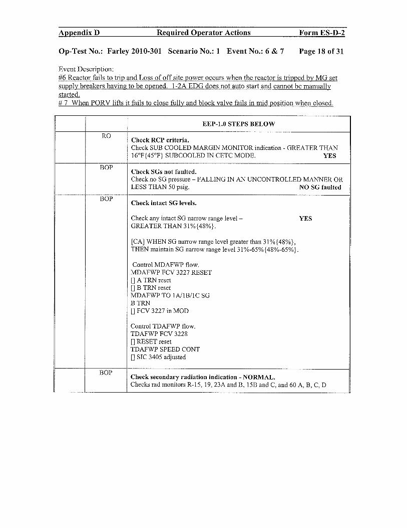
Op-Test No.: Farley 2010-301 Scenario No.: 1 Event No.: 6 & 7 Page 18 of 31
Event Description:#6 Reactor fails to trip and Loss of off site power occurs when the reactor is tripped by MG setsupply breakers having to be opened. 1 -2A EDG does not auto start and cannot be manuallystarted.# 7 When PORV lifts it fails to close fully and block valve fails in mid position when closed.
EEP-1.O STEPS BELOW
ROCheck RCP criteria.Check SUB COOLED MARGIN MONITOR indication - GREATER THAN16°F{45°F} SUBCOOLED IN CETC MODE. YES
BOPCheck SGs not faulted.Check no SO pressure - FALLING IN AN UNCONTROLLED MANNER ORLESS THAN 50 psig. NO SG faulted
BOPCheck intact SG levels.
Check any intact SO narrow range level YESGREATER THAN 31%{48%}.
[CA] WHEN SG narrow range level greater than 3l%{48%},THEN maintain SG narrow range level 31 %-65% {48%-65%}.
Control MDAFWP flow.MDAFWP FCV 3227 RESET
[] A TRN reset[] B TRN resetMDAFWP TO lA/lB/iC SOB TRN
[] FCV 3227 in MOD
Control TDAFWP flow.TDAFWP FCV 3228[] RESET resetTDAFWP SPEED CONT[] SIC 3405 adjusted
BOPCheck secondary radiation indication - NORMAL.Checks rad monitors R-15, 19, 23A and B, 15B and C, and 60 A, B, C, D
Appendix D Required Operator Actions Form ES-D-2
Op-Test No.: Farley 2010-301 Scenario No.: 1 Event No.: 6 & 7 Page 18 of 31
Event Description: #6 Reactor fails to trip and Loss of off site power occurs when the reactor is tripped by MG set supply breakers having to be opened. 1-2A EDG does not auto start and cannot be manually started. # 7 When PORV lifts it fails to close fully and block valve fails in mid position when closed.
EEP-1.0 STEPS BELOW
RO Check RCP criteria. Check SUB COOLED MARGIN MONITOR indication - GREATER THAN 16°F {4S0F} SUBCOOLED IN CETC MODE. YES
BOP Check SGs not faulted. Check no SG pressure - FALLING IN AN UNCONTROLLED MANNER OR LESS THAN SO psig. NO SG faulted
BOP Check intact SG levels.
Check any intact SG narrow range level- YES GREATER THAN 31%{48%}.
[CAl WHEN SG narrow range level greater than 31 %{48%}, THEN maintain SG narrow range level 31 %-6S% {48%-6S%}.
Control MDAFWP flow. MDAFWP FCV 3227 RESET [] A TRN reset [] B TRN reset MDAFWP TO 1A/IBIl C SG BTRN [] FCV 3227 in MOD
Control TDAFWP flow. TDAFWP FCV 3228 [] RESET reset TDAFWP SPEED CONT [] SIC 340S adjusted
BOP Check secondary radiation indication - NORMAL. Checks rad monitors R-1S, 19, 23A and B, lSB and C, and 60 A, B, C, D

Appendix D Required Operator Actions Form ES-D-2
Op-Test No.: Farley 2010-301 Scenario No.: 1 Event No.: 6 & 7 Page 19 of 31
Event Description:#6 Reactor fails to trip and Loss of off site power occurs when the reactor is tripped by MG setsupply breakers having to be opened. 1-2A EDG does not auto start and cannot be manuallystarted.# 7 When PORV lifts it fails to close fully and block valve fails in mid position when closed.
RO Check pressurizer PORVsCheck any PRZR PORV ISO — power available[CA] WHEN pressurizer pressure less than 2335 psig,
THEN verify pressurizer PORVs closed with no leakage.
Verify both PRZR PORVs - CLOSED NO
Check PRZR PORV temperature STABLE OR FALLiNG.[]PORV Temp TI-463
Check PRT parameters STABLE or FALLING.[]PRT PRESS P1 472[]PRT LVL LI-470[]PRT TEMP TI-47 1
Check at least one PRZR PORV ISO - OPEN
The following will be passed off to the Shift ManagerPerform the following within 1 hour of start of event.
o Close recirculation valve disconnects using ATTACHMENT 1.o Establish 1A and lB post LOCA containment hydrogen analyzers IN
SERVICE USING ATTACHMENT 2, POST LOCACONTAINMENT HYDROGEN ANALYZER OPERATION.
o Plot hydrogen concentration on FIGURE 1.o Check containment H2 concentration - LESS THAN 3.5%.
[CA] Check SI termination criteriao Check SUB COOLED MARGIN MONITOR indication - GREATER
THAN 16°F{45°F} SUBCOOLED IN CETC MODE.o Check secondary heat sink available.
>395 gpm AFW flow OR> 31%{48%} SGNR level
o Check RCS pressure - STABLE OR RISINGo Check pressurizer level GREATER THAN 13% {43%}.
Continue to the next step since a known LOCA exists
RO[CAl Check containment spray system.
Check any CS PUMP - STARTED. NO
Appendix D Required Operator Actions Form ES-D-2
Op-Test No.: Farley 2010-301 Scenario No.: 1 Event No.: 6 & 7 Page 19 of31
Event Description: #6 Reactor fails to trip and Loss of off site power occurs when the reactor is tripped by MG set supply breakers having to be opened. 1-2A EDG does not auto start and cannot be manually started. # 7 When PORV lifts it fails to close fully and block valve fails in mid position when closed.
RO Check pressurizer PORVs Check any PRZR PORV ISO - power available [CA] WHEN pressurizer pressure less than 2335 psig,
THEN verify pressurizer PORVs closed with no leakage.
VerifybothPRZR PORVs - CLOSED NO
Check PRZR PORV temperature STABLE OR FALLING. [] PORV Temp TI-463
Check PRT parameters STABLE or FALLING. [] PRT PRESS PI 472 [] PRT L VL LI-470 [] PRT TEMP TI-471
Check at least one PRZR PORV ISO - OPEN
SS The following will be passed off to the Shift Manager Perform the following within 1 hour of start of event.
0 Close recirculation valve disconnects using ATTACHMENT 1. 0 Establish lA and 1B post LOCA containment hydrogen analyzers IN
SERVICE USING ATTACHMENT 2, POST LOCA CONTAINMENT HYDROGEN ANALYZER OPERATION.
0 Plot hydrogen concentration on FIGURE 1. 0 Check containment H2 concentration - LESS THAN 3.5%.
SS [CA] Check SI termination criteria
0 Check SUB COOLED MARGIN MONITOR indication - GREATER THAN 16°F {45°F} SUB COOLED IN CETC MODE.
0 Check secondary heat sink available. >395 gpm AFW flow OR >31%{48%} SGNRlevel
0 Check RCS pressure - STABLE OR RISING 0 Check pressurizer level GREATER THAN 13%{43%}.
Continue to the next stel! since a known LOCA exists
RO [CAl Check containment spray system.
Check any CS PUMP - STARTED. NO

Appendix D Required Operator Actions Form ES-D-2
Op-Test No.: Farley 2010-301 Scenario No.: 1 Event No.: 6 & 7 Page 20 of 31
Event Description:#6 Reactor fails to trip and Loss of off site power occurs when the reactor is tripped by MG setsupply breakers having to be opened. 1 -2A EDG does not auto start and cannot be manuallystarted.# 7 When PORV lifts it fails to close fully and block valve fails in mid position when closed.
RO[CA] Check if LHSI Pumps should be stopped.
Check RCS pressure — GREATER THAN 275 psig{435 psig} YES
PT-402 AND 403
Check RCS pressure - STABLE OR RISING YES
Verify the SI reset
Secure any running RHR pumps Take HS to stop
SS Evaluation point —
. Check no SG pressure - FALLING IN AN UNCONTROLLED MANNER.
. Check RCS pressure on PT-4021403.This differentiates between a steam break and an RCS leak
SS should direct the team to continue in EEP- 1.To decrease run time scenario may be terminated heie Theie aie no ciiticaltasks past this point once the SI loads have been started
When SI loads are started and the transition back to EEP-l or EEP-0, end the scenario. (2 hours onvalidation to get to ESP-l.2.)
END OF SCENARIO
Appendix D Required Operator Actions Form ES-D-2
Op-Test No.: Farley 2010-301 Scenario No.: 1 Event No.: 6 & 7 Page 20 of 31
Event Description: #6 Reactor fails to trip and Loss of off site power occurs when the reactor is tripped by MG set supply breakers having to be opened. 1-2A EDG does not auto start and cannot be manually started. # 7 When PORV lifts it fails to close fully and block valve fails in mid position when closed.
RO [CAl Check ifLHSI Pumps should be stopped.
Check RCS pressure - GREATER THAN 275 psig{435 psig} YES
PT -402 AND 403
Check RCS pressure - STABLE OR RISING YES
Verify the SI reset
Secure any running RHR pumps Take HS to stop
SS Evaluation point -
• Check no SG pressure - FALLING IN AN UNCONTROLLED MANNER .
• Check RCS pressure on PT-40Z1403 . This differentiates between a steam break and an RCS leak
SS should direct the team to continue in EEP-l. To decrease run time scenario may be terminated here. There are no critical tasks past this point once the S1 loads have been started.
When SI loads are started and the transition back to EEP-l or EEP-O, end the scenario. (2 hours on validation to get to ESP-1.2.)
END OF SCENARIO

Appendix D Required Operator Actions Form ES-D-2
Op-Test No.: Farley 2010-301 Scenario No.: 1 Event No.: 8 Page 21 of 31
Event Description: ECP-0 entered here and steps below TAB 1# 8 lB DG trips 10 minutes after RCS pressure decreases to 1850 psig.
Time Position Applicant’s Action or BehaviorAnnunciators: Recognize indications of LOSS OF ALL AC- numerous - All lights in CR go out, then re-energize when
Unit 2 DGs tie on.- All Unit 1 41 60V emergency busses are de
energized
ECP-O STEPS HERE
lB DG trips 10 minutes after RCS pressure decreases to 1850 psig. A loss of ALL AC will start.
SS Recognize Loss of all AC and do IOAs of ECP-0:
RO/BOP Immediate Operator actions of ECP-0Check reactor tripped. No power1.1 Check reactor trip and reactor trip bypass breakers - OPEN.1.1.1 Manually trip reactor.[1 Reactor trip breaker A[]Reactor trip breaker B[]Reactor trip bypass breaker A[]Reactor trip bypass breaker B
IF any reactor trip breaker NOT open or any reactor trip bypass breaker NOTopen, THEN locally open affected breaker. (121 ft, AUX BLDG rod controlroom) call for this ROVER if not already done
Check nuclear power - FALLING. YESPR1(2,3,4) PERCENT FULL POWER[]NI 4lB[]NI 42B[]N143B[]NI 44B
IR1(2) CURRENT{] NI 35B[]NI 36B
Check turbine tripped. YES[]TSLB2 14-1 lit[]TSLB2 14-2 lit[]TSLB2 14-3 lit{] TSLB2 14-4 lit
Appendix D Required Operator Actions Form ES-D-2
Op-Test No.: Farley 2010-301 Scenario No.: 1 Event No.: 8 Page 21 of31
Event Description: ECP-O entered here and steps below TAB! # 8 1B DG triQs 10 minutes after RCS Qressure decreases to 1850 Qsig
Time Position Annunciators: - numerous
Applicant's Action or Behavior Recognize indications of LOSS OF ALL AC - All lights in CR go out, then re-energize when
Unit 2 DGs tie on. - All Unit 1 4160V emergency busses are de
energized
ECP-O STEPS HERE
IB DG trips 10 minutes after RCS pressure decreases to 1850 psig. A loss of ALL AC will start.
SS Recognize Loss of all AC and do IOAs ofECP-O:
RO/BOP Immediate Operator actions ofECP-O Check reactor tripped. No power 1.1 Check reactor trip and reactor trip bypass breakers - OPEN. 1.1.1 Manually trip reactor. [] Reactor trip breaker A [] Reactor trip breaker B [] Reactor trip bypass breaker A [] Reactor trip bypass breaker B
IF any reactor trip breaker NOT open or any reactor trip bypass breaker NOT open, THEN locally open affected breaker. (121 ft, AUX BLDG rod control room) call for this ROVER if not already done
Check nuclear power - FALLING. PR1(2,3,4) PERCENT FULL POWER [] NI 41B [] NI 42B [] NI43B [] NI44B
IR1(2) CURRENT [] NI 35B [] NI 36B
Check turbine tripped. [] TSLB2 14-1 lit [] TSLB2 14-2 lit [] TSLB2 14-3 lit [] TSLB2 14-4 lit
YES
YES

Appendix D Required Operator Actions Form ES-D-2
Op-Test No.: Farley 2010-301 Scenario No.: 1 Event No.: 8 Page 22 of 31
Event Description: ECP-0 entered here and steps below TAB 1# 8 lB DG trips 10 minutes after RCS pressure decreases to 1850 psig.
ROVerify RCS isolated.
o WHEN RCS pressure less than 2335 psig, THEN verify both PRZRPORVs closed.
o Verify normal letdown isolated. YESAll orifice isolation valves closed or leltdown isolation valves closed
o Verify excess letdown line - ISOLATED. YESVerify Closed HV 8153 and 8154
o Verify all reactor vessel head vent valves CLOSED.RX VESSEL HEAD VENT OUTER ISO[] Q1B135V2213A
[] Q1B135V2213B
RX VESSEL HEAD VENT INNER ISO[] Q1B13SV2214A
[j Q1B13SV2214B
BOP/ROVerify total AFW flow GREATER THAN 395 gpm.AFW TOTAL FLOW
fl Fl 3229
Appendix D Required Operator Actions Form ES-D-2
Op-Test No.: Farley 2010-301 Scenario No.: 1 Event No.: 8 Page 22 of31
Event Description: ECP-O entered here and steps below TAB! # 8 1B DG trips 10 minutes after RCS :Rressure decreases to 1850 :Rsig
RO Verify ReS isolated.
0 WHEN RCS pressure less than 2335 psig, THEN verify both PRZR PORVs closed.
0 Verify normal letdown isolated. YES All orifice isolation valves closed or leltdown isolation valves closed
0 Verify excess letdown line - ISOLATED. YES Verify Closed HV 8153 and 8154
0 Verify all reactor vessel head vent valves - CLOSED. RX VESSEL HEAD VENT OUTER ISO [] QIB13SV2213A [] QIB13SV2213B
RX VESSEL HEAD VENT INNER ISO [] QIB13SV2214A [] QIB13SV2214B
BOP/RO Verify total AFW flow GREATER THAN 395 gpm. AFW TOTAL FLOW D FI3229

Appendix D Required Operator Actions Form ES-D-2
Op-Test No.: Farley 2010-301 Scenario No.: 1 Event No.: 8 Page 23 of 31
Event Description: ECP-0 entered here and steps below TAB 1# 8 lB DG trips 10 minutes after RCS pressure decreases to 1850 psig.
BOP [CAl Restore power to any emergency bus.Verify supply breakers for major loads on emergency 4160 V busses -
OPEN.
[I BKR DFO1 (1A SIU XFMR TO iF 4160 V BUS)
El BKR DF15 (lB S[U XFMR TO iF 4160 V BUS)
[ BKR DF-i3-i (iF 4160 V BUS TIE TO iH 4160 V BUS)
[]BKR DGO1 (1A S/U XFMR TO 1G 4160 V BUS)
[]BKR DG15 (lB S/U XFMR TO 1G 4160 V BUS
[hA BATT CHARGER BKR ED-04-1
[]1C BATT CHARGER A TRN BKRED-09-i
[1 iC BATT CHARGER B TRN BKR EE-06-i
El lB BATT CHARGER BKR EE-05-1
[1 1C CCW PUMP BKR DF-04-i
El lB CCW PUMP BKR DF-05-i
[]1B CCW PUMP BKR DG-05-i
[]iA CCW PUMP BKR DG-04-1
[j1A SW PUMP BKR DK-03-i
[1 lB SW PUMP BKR DK-04-i
[]1C SW PUMP BKR DK-05-1
[1 1C SW PUMP BKR DL-05-i
El 1D SW PUMP BKR DL-03-1
El 1E SW PUMP BKR DL-04-1
[1 #4 RW PUMP BKR DJ-03-1
El #5 RW PUMP BKR DJ-04-1
El #8 RW PUMP BKR DH-03-i
[1 #9 RW PUMP BKR DH-04-i
[]#i0 RW PUMP BKR DH-05-1
El lB CRDM CLG FAN BKR ED-li-i
El 1A CRDM CLG FAN BKR EE-13-i
[I lÀ CS PUMP BKR DF-ii-l
El lB CS PUMP BKR DG-l1-i
El lÀ RIIR PUMP BKR DF-09-1
El lB RHR PUMP BKR DG-09-i
El 1A CHG PUMP BKR DF-06-i
[1 lB CHG PUMP A TRN BKR DF-07-l
El lB CHG PUMP B TRN BKR DG-07-l
El 1C CHG PUMP BKR DG-06-l
El lA MDAFWP BKR DF-l0-l
[]1B MDAFWP BKR DG-10-1
Appendix D Required Operator Actions Form ES-D-2
Op-Test No.: Farley 2010-301 Scenario No.: 1 Event No.: 8 Page 23 of31
Event Description: ECP-O entered here and steps below TAB! # 8 1B DG tril2s 10 minutes after RCS 2ressure decreases to 1850 2sig
BOP [CA] Restore power to any emergency bus. Verify supply breakers for major loads on emergency 4160 V busses-OPEN.
[] BKR DFOI (IA S/U XFMR TO IF 4160 V BUS)
[] BKR DF15 (lB S/u XFMR TO IF 4160 V BUS)
[] BKR DF-13-1 (IF 4160 V BUS TIE TO IH 4160 V BUS)
[] BKR DGOI (IA S/u XFMR TO IG 4160 V BUS)
[] BKR DG15 (lB S/u XFMR TO IG 4160 V BUS
[] lA BATT CHARGER BKR ED-04-1
[] lC BATT CHARGER A TRN BKRED-09-1
[] 1 C BATT CHARGER B TRN BKR EE-06-1
[] lB BATT CHARGER BKR EE-05-1
[] lC CCW PUMP BKR DF-04-1
[] IB CCW PUMP BKR DF-05-1
[] lB CCW PUMP BKR DG-05-1
[] lA CCW PUMP BKR DG-04-1
[] lA SW PUMP BKR DK-03-1
[] lB SW PUMP BKR DK-04-1
[] lC SW PUMP BKR DK-05-1
[] lC SW PUMP BKR DL-05-1
[] ID SW PUMP BKR DL-03-1
[] IE SW PUMP BKR DL-04-1
[] #4 RW PUMP BKRDJ-03-1
[] #5 RW PUMP BKR DJ-04-1
[] #8 RW PUMP BKR DH-03-1
[] #9 RW PUMP BKR DH-04-1
[] #10 RW PUMP BKRDH-05-1
[] lB CRDM CLG FAN BKR ED-ll-l
[] lA CRDM CLG FAN BKR EE-13-1
[] lA CS PUMP BKR DF-ll-l
[] lB CS PUMP BKR DG-ll-l
[] lA RHR PUMP BKR DF-09-1
[] lB RHR PUMP BKR DG-09-1
[] lA CHG PUMP BKR DF-06-1
[] lB CHG PUMP A TRN BKR DF-07-1
[] lB CHG PUMP B TRN BKR DG-07-1
[] lC CHG PUMP BKR DG-06-1
[] lA MDAFWP BKR DF-I0-l
[] lB MDAFWP BKR DG-I0-l

Appendix D Required Operator Actions Form ES-D-2
Op-Test No.: Farley 2010-301 Scenario No.: 1 Event No.: 8 Page 24 of 31
Event Description: ECP-0 entered here and steps below TAB 1# 8 lB DG trips 10 mi’utes after RCS pressure decreases to 1850 psig.
BOP Check 1-2A, 1C or lB diesel generator running for Unit 1. NO
(CT) Critical task
Perform 2C DG SBO start:o MSS in MODE 1o USS in UNIT 1o When load shed has been competed then depress START PB
2C DG will start
o Verify Unit 1 2C DG output breaker DJO6 closes. YESo Verify breaker DG1 3 closed. ( 1G 4160 V bus
tie to 1J416OVBUS)o Verify breaker DGO2 closed. (1 G 4160 V bus
tie to lL4l6OVbus)o IF 1G 4160V bus energized, THEN proceed to YES
step 5.7
BOPVerify adequate SW flow.
o Verify two SW PUMPS in energized train - RUNNING. NO[] A Train (1A, lB or 1C)[] B Train (1D, 1E or 1C) START 1D AND 1E SW PUMP
o IF A train energized, THEN verify SW TO/FROM DG NOBLDG - A HDR Q1P16V519/537 open.
o IF B train energized, THEN verify SW TO/FROM DG YESBLDG - B HDR Q1P16V518/536 open.
BOPCheck no running diesel generator lube oil temperature annunciator inalarm. (155 ft, DG BLDG local control panel) NO
SSIF iF OR 1G 4160 V bus energized THEN go to procedure and stepin effect and implement function restoration procedures as necessary.
SSDirect OATC or UO to start the following SI loads on B Train at a minimum for
(CT)core cooling:
• CCW pump START 1A CCW PUMP
• Chg pump START 1C HUSI PUMP
Depending on SGWL, start the MDAFW pump. START lB MDAFW PUMP
May start the lB RHR pump but this is not critical since RCS pressure is > 500psig.
Return procedure and step in effect, EEP-O or EEP-l.O from event 7.
To decrease run time scenario may be terminated here. There are no critical tasks past this point once the SIloads are returned to service.
Appendix D Required Operator Actions Form ES-D-2
Op-Test No.: Farley 2010-301 Scenario No.: 1 Event No.: 8 Page 24 of31
Event Description: ECP-O entered here and steps below TAB 1 # 8 1B DG trips 10 minutes after RCS Qressure decreases to 1850 Qsig
(CT)
(CT)
BOP
BOP
BOP
SS
SS
Check 1-2A, IC or IB diesel generator running for Unit l.
Critical task
Perform 2C DG SBO start: o MSS in MODE I o USS in UNIT I
NO
o When load shed has been competed then depress START PB 2C DG will start
o Verify Unit 1 2C DG output breaker DJ06 closes. o Verify breaker DG 13 closed. (1 G 4160 V bus
tie to 1J 4160 V BUS) o Verify breaker DG02 closed. (1 G 4160 V bus
tie to 1L 4160 V bus) o IF 1 G 4160V bus energized, THEN proceed to
step 5.7
Verify adequate SW flow.
YES
YES
o Verify two SW PUMPS in energized train - RUNNING. NO [] A Train (lA, 1B or 1C) [] B Train (ID, IE or IC) START ID AND IE SW PUMP
o IF A train energized, THEN verify SW TOIFROM DG NO BLDG - A HDR Q1P16V519/537 open.
o IF B train energized, THEN verify SW TO/FROM DG YES BLDG - B HDR Q1P16V518/536 open.
Check no running diesel generator lube oil temperature annunciator in alarm. (155 ft, DG BLDG local control panel) NO
IF IF OR 1 G 4160 V bus energized THEN go to procedure and step in effect and implement function restoration procedures as necessary.
Direct OATC or UO to start the following SI loads on B Train at a minimum for core cooling:
• CCWpump
• Chgpump
START IA CCW PUMP
START I C HHSI PUMP
Depending on SGWL, start the MDAFW pump. START 1B MDAFW PUMP
May start the 1B RHR pump but this is not critical since RCS pressure is > 500 psig.
Return procedure and step in effect, EEP-O or EEP-l.O from event 7.
To decrease run time scenario may be terminated here. There are no critical tasks past this point once the SI loads are returned to service.

Appendix D Required Operator Actions Form ES-D-2
Op-Test No.: Farley 2010-301 Scenario No.: 1 Event No.: 6 Page 25 of 31
Event Description: Attachment 2 and 4 of EEP-0
Cue: BOP will accomplish when at step 5 of EEP-O
Time Position Applicant’s Action or Behavior
Attachment 2 of EEP-O
AUTOMATIC ACTIONS VERIFICATION
1 Verify each SW train - HAS TWO SW PUMPs STARTED.BOP [] A train (1A,1B or 1C)
[]Btrain(1D,lEorlC)
2 Verify each train of CCW - STARTED.2.1 Verify one CCW PUMP in each train- STARTED.A train HX 1C or lB CCW FLOW[1 Fl 3043CA > 0 gpmOR
[] FT 3043BA> 0 gpmB trainHX 1A or lBCCW FLOW[] FT 3043AA> 0 gpmOR[] Fl 3043BA > 0 gpm
Verify SW flow to associated CCW HX’sSW FROM 1A(1B, 1C) CCW HX[] Q1P16FI3009AA >0 gpm[] Q1P16FI3009BA> 0 gpm[] Q1P16FI3009CA >0 gpm
BOP Check instrument air available. NO. No IA compressor running. IA press < 85 psig
Initiate action to place SW from the in service CCW HXs on the jack perFNP-1-SOP-23.0, COMPONENT COOLING WATER SYSTEM.
. Q1P16FV3009A
. Q1P16FV3009B
. QIP16FV3009C
Verify one CHG PUMP in each train - STARTED.
[] A train (1A or 1B) amps > 0
BOP [] B train (1C or 1B) amps >0
Appendix D Required Operator Actions
Op-Test No.: Farley 2010-301 Scenario No.: 1 Event No.: 6
Event Description: Attachment 2 and 4 ofEEP-O
Cue: BOP will accomplish when at step 5 ofEEP-O
Time Position Applicant's Action or Behavior
Attachment 2 of EEP-O
AUTOMATIC ACTIONS VERIFICATION
Form ES-D-2
Page 25 of31
1 Verify each SW train - HAS TWO SW PUMPs STARTED. BOP [] A train (IA,IB or lC)
[] B train (lD, 1E or 1 C)
BOP
2 Verify each train of CCW - STARTED. 2.1 Verify one CCW PUMP in each train- STARTED. A train HX lC or lB CCW FLOW [] FI 3043CA > 0 gpm OR [] FI 3043BA > 0 gpm B train HX lA or lB CCWFLOW [] FI 3043AA > 0 gpm OR [] FI 3043BA > 0 gpm
Verify SW flow to associated CCW HX's SW FROM lA(lB, lC) CCW HX [] QIPI6FI3009AA > 0 gpm [] QIPI6FI3009BA > 0 gpm [] QIPI6FI3009CA > 0 gpm
Check instrument air available. • No IA compressor running • IA press < 85 psig
NO
Initiate action to place SW from the in service CCW HX's on the jack per FNP-1-S0P-23.0, COMPONENT COOLING WATER SYSTEM.
• Q1 P16FV3009A • Q1P16FV3009B • Q1 P16FV3009C
Verify one CHG PUMP in each train - STARTED.
[] A train (lA or lB) amps> 0
BOP [] B train (IC or IB) amps> 0

Appendix B Reiuired Operator Actions Form ES-D-2
Op-Test No.: Farley 2010-301 Scenario No.: 1 Event No.: 6 Page 26 of 31
Event Description: Attachment 2 and 4 of EEP-O
BOP Verify RBR PUMPs - STARTED.
RHR PUMP
[] lAamps>O
[] lBamps>O
BOP Verify Safety Injection Flow.
Check HHSI flow - GREATER THAN 0 gpm.
[] Fl 943
BOP Check RCS pressure - LESS THAN 275 psig{435 psig}. NO
BOP 6 Verify containment ventilation isolation.
6.1 Verify containment purge dampers - CLOSED.
[] 3197
[] 3198D
[] 3198C
[] 3196
[] 3198A
[] 3198B
6.2 Verify containment mini purge dampers - CLOSED.
CTMT PURGE DMPRS
MINI-2866C & 2867C
FULL-3198A & 3198D
[]2866C
[]2867C
CTMT PURGE DMPRS
MINI-2866D & 2867D
FULL-3196 & 3197
BOTH-3198B & 3198C
[]2866D
[j 2867D
6.3 Stop MINI PURGE SUPP!EXH FAN. Will place HS toSTOP
Appendix D Required Operator Actions Form ES-D-2
Op-Test No.: Farley 2010-301 Scenario No.: 1 Event No.: 6 Page 26 of31
Event Description: Attachment 2 and 4 of EEP-O
BOP Verify RHR PUMPs - STARTED.
RHRPUMP
[] 1A amps> 0
[] 1B amps> 0
BOP Verify Safety Injection Flow.
Check HHSI flow - GREATER THAN 0 gpm.
[] FI 943
BOP CheckRCS pressure - LESS THAN 275 psig{435 psig}. NO
BOP 6 Verify containment ventilation isolation.
6.1 Verify containment purge dampers - CLOSED.
[] 3197
[] 3198D
[] 3198C
[] 3196
[]3198A
[]3198B
6.2 Verify containment mini purge dampers - CLOSED.
CTMT PURGE DMPRS
MINI-2866C & 2867C
FULL-3198A & 3198D
[] 2866C
[] 2867C
CTMT PURGE DMPRS
MINI-2866D & 2867D
FULL-3196 & 3197
BOTH-3198B & 3198C
[] 2866D
[] 2867D
6.3 Stop MINI PURGE SUPP/EXH FAN. Will place HS to STOP

Appendix D Required Operator Actions Form ES-D-2
Op-Test No.: Farley 2010-301 Scenario No.: 1 Event No.: 6 Page 27 of 31
Event Description: Attachment 2 and 4 of EEP-O
BOP 7 Verify containment fan cooler alignment.
7.1 Verify at least one containment fan cooler per train - STARTED IN SLOWSPEED.
CTMT CLR FAN SLOW SPEED
[ A train
[]1A
{] lB
[1 B train
[] 1C
[] 1D
7.2 Verify associated emergency service water outlet valves - OPEN.
EMERG SW FROM 1A(1B,1C,1D) CTMT CLR
[] Q1P16MOV3O24A
[] Q1P16MOV3O24B
[] Q1P16MOV3O24C
[] Q1P16MOV3O24D
BOP 8 Verify AFW Pumps - STARTED.
8.1 Verify both MDAFW Pumps - STARTED
[] 1A MDAFW Pump amps > 0
[] lB MDAFW Pump amps > 0
AND
[] FI-3229A indicates > 0 gpm
[] FI-3229B indicates > 0 gpm
[J FI-3229C indicates > 0 gpm
8.2 Check TDAFW Pump start required.
LI Condition LITSLB LI Setpoint LI Coincidence [I
RCP Bus TSLB2 1-1 [2680 V 1/2 Detectors
Undervoltage 1-2 1-3 on 2/3 Busses
Low Low SG TSLB4 28% 2/3 Detectors
Water Level 4-1,4-2,4-3 on 2/3 SGs
In Any 5-1,5-2,5-3
2/3 SGs 6-1,6-2,6-3
Appendix D Required Operator Actions Form ES-D-2
Op-Test No.: Farley 2010-301 Scenario No.: 1 Event No.: 6 Page 27 of31
Event Description: Attachment 2 and 4 ofEEP-O
BOP 7 Verify containment fan cooler alignment.
7.1 Verify at least one containment fan cooler per train - STARTED IN SLOW SPEED.
CTMT CLR FAN SLOW SPEED
o A train
[]1A
[]1B
o B train
[]1C
[] lD
7.2 Verify associated emergency service water outlet valves - OPEN.
EMERG SW FROM lA(1B,IC,lD) CTMT CLR
[] QIP16MOV3024A
[] QIP16MOV3024B
[] QIP16MOV3024C
[] QIP16MOV3024D
BOP 8 Verify AFW Pumps - STARTED.
8.1 Verify both MDAFW Pumps - STARTED
[] lA MDAFW Pump amps> 0
[] 1B MDAFW Pump amps> 0
AND
[] FI-3229A indicates> 0 gpm
[] FI-3229B indicates> 0 gpm
[] FI-3229C indicates> 0 gpm
8.2 Check TDAFW Pump start required.
o Condition OTSLB DSe!,Qoint [J Coincidence [J
RCP Bus TSLB21-1 02680 V 112 Detectors
Undervoltage 1-2 1-3 on 2/3 Busses
LowLowSG TSLB4 28% 2/3 Detectors
Water Level 4-1,4-2,4-3 on 2/3 SGs
In Any 5-1,5-2,5-3
2/3 SGs 6-1,6-2,6-3

Appendix D Required Operator Actions Form ES-D-2
Op-Test No.: Farley 2010-301 Scenario No.: 1 Event No.: 6 Page 28 of 31
Event Description: Attachment 2 and 4 of EEP-0
BOP 8.3 Verify TDAFWP started.[j MLB-4 1-3 lit[j MLB-4 2-3 lit
[J MLB-4 3-3 lit
TDAFWP SPEED[] SI 341 1A> 3900 rpm
TDAFWP SPEED CONT
[] SIC 3405 adjusted to 100%
8.4 Verify TDAFW flow path to each SG.TDAFWP TO 1A(1B,1C) SG[] Q1N23HV3228A in MOD[] Q1N23HV3228B in MOD{] Q1N23HV3228C in MOD
TDAFWP TO 1A(1B,1C) SG FLOW CONT[] HIC 3228AA open[] HIC 3228BA open[] HIC 3228CA open
BOP9 Verify main feedwater status.9.1 Verify main feedwater flow control and bypass valves - CLOSED.1A(1B,1C) SG FW FLOW[] FCV 478[] FCV 488[1 FCV 498
9.2 Verify both SGFPs - TRIPPED.
9.3 Verify SG blowdown - ISOLATED.1A(1B,1C) SGBD ISO[] Q1G24HV7614A closed[] Q1G24HV7614B closed[] Q1G24HV7614C closed
9.4 Verify SC blowdown sample - ISOLATED MLB lights lit.1A(1B,1C) SGBD SAMPLE STEAM GEN ISO[j MLB1 19-2 lit Q1P15HV3328 closed[J MLB1 19-3 lit Q1P15HV3329 closed[] MLB1 19-4 lit Q1P15HV3330 closed
Appendix D Required Operator Actions Form ES-D-2
Op-Test No.: Farley 2010-301 Scenario No.: 1 Event No.: 6 Page 28 of 31
Event Description: Attachment 2 and 4 ofEEP-O
BOP 8.3 Verify TDAFWP started. [] MLB-4 1-3 lit [] MLB-4 2-3 lit [] MLB-4 3-3 lit
TDAFWP SPEED [] SI 3411A > 3900 rpm
TDAFWP SPEED CONT [] SIC 3405 adjusted to 100%
8.4 Verify TDAFW flow path to each SG. TDAFWP TO 1A(1B,1C) SG [] Q1N23HV3228A in MOD [] Q1N23HV3228B in MOD [] Q1N23HV3228C in MOD
TDAFWP TO 1A(lB,1C) SG FLOW CONT [] HIC 3228AA open [] HIC 3228BA open [] HIC 3228CA open
BOP 9 Verify main feedwater status. 9.1 Verify main feedwater flow control and bypass valves - CLOSED. 1A(lB,1C) SG FW FLOW [] FCV 478 [] FCV 488 [] FCV 498
9.2 Verify both SGFPs - TRIPPED.
9.3 Verify SG blowdown - ISOLATED. 1A(lB,1C) SGBD ISO [] Q1G24HV7614A closed [] Q1G24HV7614B closed [] Q1G24HV7614C closed
9.4 Verify SG blowdown sample - ISOLATED MLB lights lit. 1A(1B,1C) SGBD SAMPLE STEAM GEN ISO [] MLB1 19-2 lit Q1P15HV3328 closed [] MLB1 19-3 lit Q1P15HV3329 closed [] MLB1 19-4 lit Q1P15HV3330 closed

Appendix D Required Operator Actions Form ES-D-2
Op-Test No.: Farley 2010-301 Scenario No.: 1 Event No.: 6 Page 29 of 31
Event Description: Attachment 2 and 4 of EEP-O
BOP 10 Check no main steam line isolation actuation signal present.
Signal Setpoint coincidence TSLB
LO SG PRESS < 585 psig 2/3 TSLB4 19-2,3,4
Hi stm flow >40% ‘/2 on 2/3 TSLB4 16-3,4
and and 17-3,4 18-3,4
Lo-Lo Tavg <543°F 2/3 TSLB2 10-1,2,3
HI-HI ctrnt press >16.2 psig 2/3 TSLB1 2-2,3,4
(CT) Critical task
BOP 11 Verify PHASE A CTMT ISO. NO
11.1 Verif’ PHASE A CTMT ISO - ACTUATED. Will actuate handswitchto actuate phase A
[] MLB-2 1-1 lit
[] MLB-2 11-1 lit
11.2 Check all MLB-2 lights - LIT. 11.2 Verify PHASE A CTMTISO alignment using ATTACH3, PHASE A CTMT ISO
BOP 12 Check all reactor trip and 12 Perform the following.reactor trip bypass breakers - OPEN. 12.1 Open reactor trip
breaker(s) manually from MCBor locally.
Reactor trip breaker A 12.2 Record any breaker(s) Reactortrip breaker B manually opened.Reactor trip bypass breaker AReactor trip bypass breaker B
BOP 13 Trip CRDM MG set supply breakers.
lA(1B) MG SET SUPP BKR
[] N1C11EOO5A
[] N1C11EOO5B
Appendix D Required Operator Actions Form ES-D-2
Op-Test No.: Farley 2010-301 Scenario No.: 1 Event No.: 6 Page 29 of 31
Event Description: Attachment 2 and 4 ofEEP-O
BOP 10 Check no main steam line isolation actuation signal present.
Signal Semoint coincidence TSLB
LO SGPRESS < 585 psig 2/3 TSLB4 19-2,3,4
Hi stm flow >40% Yz on 2/3 TSLB4 16-3,4
and and 17-3,4 18-3,4
Lo-Lo Tavg <543°F 2/3 TSLB2 10-1,2,3
HI-HI ctmt press >16.2 psig 2/3 TSLBI 2-2,3,4
(CT) Critical task
BOP 11 Verify PHASE A CTMT ISO. NO
11.1 Verify PHASE A CTMT ISO - ACTUATED. Will actuate handswitch to actuate phase A
[] MLB-2 1-1 lit
[] MLB-2 11-1 lit
11.2 Check all MLB-2 lights - LIT. 11.2 Verify PHASE A CTMT ISO alignment using ATTACH 3, PHASE A CTMT ISO
BOP 12 Check all reactor trip and 12 Perfonn the following. reactor trip bypass breakers - OPEN. 12.1 Open reactor trip
breaker(s) manually from MCB or locally.
Reactor trip breaker A 12.2 Record any breaker(s) Reactor trip breaker B manually opened. Reactor trip bypass breaker A Reactor trip bypass breaker B
BOP 13 Trip CRDM MG set supply breakers.
lA(1B) MG SET SUPP BKR
[] NICIIE005A
[] NICIIE005B

Appendix D Required Operator Actions Form ES-D-2
Op-Test No.: Farley 2010-301 Scenario No.: 1 Event No.: 6 Page 30 of 31
Event Description: Attachment 2 and 4 of EEP-0
BOP14 Secure secondary components.14.1 Stop both heater drain pumps.HDP{]1A
[] lB
14.2 Check any condensate pump started.
14.2.1 IF started, THEN stop all but one condensate pump.[J1A
[1 lB
If NO condensate pumps are started then place all HSs to STOP
14.3 IF condensate pump operating, THEN verify backup cooling aligned tocondensate pumps per SOP-0.0, APPENDIX B, TB SO ACTIONSFOLLOWING A REACTOR TRIP OR SAFETY INJECTION.
Will call TBSO to accomplish this.
BOP 15 Verify both CRACS mode selector switches in the ON position.
CRACS Mode Selector Switch
[] A TRAIN
[] B TRAIN
Will call BOOTH to have this accomplished since this is not in thesimulator
BOP 16 WHEN at least 30 seconds have passed since turbine trip,
THEN check main generator tripped.
23OKVBKR
[] 810- OPEN
[] 914 - OPEN
BOP 17 Verify two trains of ECCS equipment aligned.
17.1 Perform ATTACHMENT 4, TWO TRAIN ECCS ALIGNMENT
VERIFICATION.
End of Attachment 2
Appendix D Required Operator Actions Form ES-D-2
Op-Test No.: Farley 2010-301 Scenario No.: 1 Event No.: 6 Page 30 of31
Event Description: Attachment 2 and 4 ofEEP-O
BOP 14 Secure secondary components. 14.1 Stop both heater drain pumps. HDP []IA [] 1B
14.2 Check any condensate pump started.
14.2.1 IF started, THEN stop all but one condensate pump. [] 1A []IB
If NO condensate pumps are started then place all HSs to STOP
14.3 IF condensate pump operating, THEN verify backup cooling aligned to condensate pumps per SOP-O.O, APPENDIX B, TB SO ACTIONS FOLLOWING A REACTOR TRIP OR SAFETY INJECTION.
Will call TBSO to accomplish this.
BOP 15 Verify both CRACS mode selector switches in the ON position.
CRACS Mode Selector Switch
[] A TRAIN
[] B TRAIN
Will call BOOTH to have this accomplished since this is not in the simulator
BOP 16 WHEN at least 30 seconds have passed since turbine trip,
THEN check main generator tripped.
230 KV BKR
[] 810 - OPEN
[] 914 - OPEN
BOP 17 Verify two trains of ECCS equipment aligned.
17.1 PerfonnATTACHMENT 4, TWO TRAIN ECCS ALIGNMENT
VERIFICATION.
End of Attachment 2

Appendix D Required Operator Actions Form ES-D-2
Op-Test No.: Farley 2010-301 Scenario No.: 1 Event No.: 6 Page 31 of 31
Event Description: Attachment 2 and 4 of EEP-O
Attachment 4TWO TRAIN ECCS ALIGNMENT VERIFICATION
BOP 1 Verify two trains of ECCS equipment aligned.Check DFO 1 closedVerify DFO2 closedCheck DG15 closedVerify DGO2 closed
Verify two trains of battery chargers — energized- Amps>O
1.6 Verify two trains of ESF equipment aligned.
Check all MLB- 1 lights LITVerify charging pump suction and discharge valves - OPEN.
CHG PUMP DISCH HDR ISO{] Q1E21MOV8132A[]Q1E21MOV8132B[]Q1E21MOV8133A[]Q1E21MOV8133BCHG PUMP SUCTION HDR ISO[]Q1E21MOV813OA[1 Q1E21MOV813OB[j Q1E21MOV8131A
[J Q1E21MOV8131B
1.7 Verify all post accident containment air mixing systemfans - STARTED. (BOP)
POST ACCIDENT MIXING FAN[]1A[]1B[]1C[liDRX CAV H2 DILUTION FAN[]1A[]1B
BOP call Radside SO to Verify Spent Fuel Pool Cooling in service per SOP-54.O,SPENT FUEL PIT COOLING AND PURIFICATION SYSTEM.
End of Attachment 4
Appendix D Required Operator Actions Form ES-D-2
Op-Test No.: Farley 2010-301 Scenario No.: 1 Event No.: 6 Page 31 of 31
Event Description: Attachment 2 and 4 ofEEP-O
Attachment 4 TWO TRAIN ECCS ALIGNMENT VERIFICATION
BOP 1 Verify two trains of ECCS equipment aligned. Check DFOI closed Verify DF02 closed Check DG 15 closed Verify DG02 closed
Verify two trains of battery chargers - energized - Amps >0
1.6 Verify two trains ofESF equipment aligned.
Check all MLB-l lights LIT Verify charging pump suction and discharge valves - OPEN.
CHG PUMP DISCH HDR ISO [] QIE21MOV8132A [] QIE21MOV8132B [] QIE21MOV8133A [] QIE21MOV8133B CHG PUMP SUCTION HDR ISO [] QIE21MOV8130A [] QIE21MOV8130B [] QIE21MOV8131A [] QIE21MOV8131B
1.7 Verify all post accident containment air mixing system fans - STARTED. (BOP)
POST ACCIDENT MIXING FAN []1A []1B []1C [] 1D RX CA V H2 DILUTION FAN []1A []1B
BOP .call Radside SO to Verify Spent Fuel Pool Cooling in service per SOP-54.0, SPENT FUEL PIT COOLING AND PURIFICATION SYSTEM.
End of Attachment 4

Appendix D Crew Briefing sheet Form ES-D-2
Op-Test No.: FA2O1O-301Page 1 of2
Brief
This simulator perfonnance scenario is performed in the EVALUATION MODE. You
should not direct questions to the evaluators. Otherwise, you should perform as if you were
in the MCR.
Your ability to maintain a log is not being graded, but maintaining a rough log is
recommended to help during briefs.
If you need to communicate with the Unit 2 operator, verbally state, “Unit 2” and an
instructor will locate to the Unit 2 area and respond to you as quickly as possible.
If you need to communicate with the Shift Manger, use the PAX phone to call if during
normal operations. If in the EOPs, then turn to the glass and address the SM for updates and
other information purposes. If you need an action done, call the SM or SSS on the phone.
In the unlikely event that the simulator fails such that illogical indications result, the session
will be terminated. In other words, respond to what you see. If there is a problem with the
simulation, the session will be terminated or adjusted as appropriate based on the specific
problem.
Assign operating positions.
Ask for and answer questions.
Appendix D Crew Briefing sheet Form ES-D-2
Op-Test No.: FA2010-301 Page 1 of2
Brief
This simulator performance scenario is performed in the EVALUATION MODE. You
should not direct questions to the evaluators. Otherwise, you should perform as if you were
in theMCR.
Your ability to maintain a log is not being graded, but maintaining a rough log IS
recommended to help during briefs.
If you need to communicate with the Unit 2 operator, verbally state, "Unit 2" and an
instructor will locate to the Unit 2 area and respond to you as quickly as possible.
If you need to communicate with the Shift Manger, use the PAX phone to call if during
normal operations. If in the EOPs, then tum to the glass and address the SM for updates and
other information purposes. If you need an action done, call the SM or SSS on the phone.
In the unlikely event that the simulator fails such that illogical indications result, the session
will be terminated. In other words, respond to what you see. If there is a problem with the
simulation, the session will be terminated or adjusted as appropriate based on the specific
problem.
Assign operating positions.
Ask for and answer questions.

Appendix D Turnover sheet Form ES-D-2
[X] Unit I [ j Unit 2 Shift: DateI Off-going SS I Oncoming SS [ ] N [Xl D Today
Part I — To be reviewed by the oncoming Supervisor prior to assuming the shift.
Security Keys A, 5, D, SW, X on key ring. SS
Unit Mode 1, 72% RTP, MOL, 1179 ppm Cb, 10,000 MWD/MTU; xe building in (-638 pcm)Status Rod control is in Manual. Ramping per UOP-3.1.
UOP-3.1, v.104, step 5.16, is complete.
STPslEvolutions B Train On-Service — B TrainSTP-27 I due in 3 Protectedhours1.0; 109.1 Noadi.
Status of Special Testing
General Information1 Current Risk Assessment is YELLOW and projected is YELLOW2. 1 C DG is tagged out. The tagging order is being prepared for RTS in the next hour.3. 1A MDAFW pump is tagged out for bearing replacement. (OOS 6 hrs, ETR 2 hrs)4. Ramp on HOLD for turnover. Plans are to start the ramp to 95% power upon taking shift.5. Severe thunderstorm warnings in effect for Southeast Alabama & Western Georgia.6.7.8.9.10.11.Equipment Status1C DG is tagged out Maintain VCT gas pressure 25-30 psig1A MDAFW pump is tagged out
Ré’aätivityPIàn WästEManagément:StatusLast shift was diluting 150 gal every 5 minutes while #3 RHT — On Serviceramping.
WGS — securedLCO StatusLCO 3.8.1 condition BLCO 3.7.5 condition BNight OrdersNo New Night OrdersPart II Review Shift Complement
LCOs Reviewed SS (initials) reviewed as early in shift as possiblePart Ill: STP-1 .0 Operator Logs Cond. Report Autolog ELDS & GEN Keys
Reviewed/Signed Reviewed Queue Reviewed Spreadsheet TurnedReviewed verified Over
[XJYes [X]Yes [X]Yes [XjYes [XjYes [X]Yes
FA2O1 0-301
Appendix D Turnover sheet Form ES-D-2
Shift: Date Oncoming SS [ 1 N [X 1 0 Today
Part 1- To be reviewed by the oncoming Supervisor prior to assuming the shift.
Security Keys A, S, D, SW, X on key ring.~
Unit Status
Mode 1,72% RTP, MOL, 1179 ppm Cb, 10,000 MWD/MTU; xe building in (-638 pcm) Rod control is in Manual. Ramping per UOP-3.1.
UOP-3.1, v.l04, step 5.16, is complete .
:SlRt:;/E'1()I.,:,ti~.~s.:.Vi./! SIP~27;1.diJein'3·· .
. BTrain· On-:Service -\BTrain.
. Protected .. ..,. ...... .
h·~O;'s·· 1 .0_; 109.1 _-----'-N=o'-'a=d:J..:,j.
F Status.ofSpeciaITestirig· '.
\/Gerierallnformatiorj 1. Current Risk Assessment is YELLOW and projected is YELLOW 2. 1 C DG is tagged out. The tagging order is being prepared for RTS in the next hour. 3. 1A MDAFW pump is tagged out for bearing replacement. (OOS 6 hrs, ETR 2 hrs) 4. Ramp on HOLD for turnover. Plans are to start the ramp to 95% power upon taking shift. 5. Severe thunderstorm warnings in effect for Southeast Alabama & Western Georgia. 6. 7. 8. 9. 10. 11.
sReactiviCPlari>\ ., . ·Was.teMana ~mentStatus Last shift was diluting 150 gal every 5 minutes while #3 RHT - On Service ram in .
Review Shift Complement LCOs Reviewed SS (initials) reviewed as early in shift as possible
Part III: STP-1.0 Operator Logs Condo Report Autolog ELDS & GEN Reviewed/Signed Reviewed Queue Reviewed Spreadsheet
Reviewed verified [ X ] Yes [ X ] Yes [ X ] Yes [ X ] Yes [ X ] Yes
FA2010-301
Keys Turned Over
[X] Yes

Appendix D Scenario 3 Outline Form ES-D-1
Facility: Farley Scenario No.: ... Op-Test No.: FA2O1 0301
Examiners: Operators:
Initial Conditions: 25% power, MOL, 1292 ppm Cb, 10,000 MWD, Xe building in from Xefree startup at 80 pcm, A Train On-Service — A Train Protected
Turnover:• Ramping to 50% power• UOP 3.1 has been completed through step 5.1.1.• lB DIG in process of being returned from maintenance condition LCO 3.8.1.• STP-27.1 in progress on both units. Surveillance is due again in 3 hours.• lB MDAFW PUMP T/O for bearing replacement. LCO-3.7.5• Ramp on hold for turnover.• Current Risk Assessment is YELLOW and projected is YELLOW.• Severe thunderstorm warnings in effect for Southeast Alabama & Western Georgia.
Event No. Maif Event EventNo. Type* Description
I R (RO & Seismic event/alarm OBE exceededBOP)
2 1 I (RO) PK-145 fails high in automatic, letdown pressure controllerfailure causes PCV-145 to close
3 2 C (BOP) Main Turbine Lube Oil Temperature Controller CP-4055Auto Output Failure
4 3 C (RO) Chg low flow due to Degraded 1C CHG pump headTS (SRO) TS 3.5.2 mandatory (and TR 13.5.1 admin)
5 4 C (BOP) CST rupture — will place SW on AFW suctionsTS (SRO) TS 3.7.6 condition A
6 5 C (RO & 1 B RCP tripsBOP)TS (SRO)
7 M (ALL) IC SG tube rupture 400 gpm when <2% power
6 C (BOP) Main Turbine does not Auto Trip
8 7 C (BOP) TDAFW pump does not auto start, must be manuallystarted from MCB. 1A MDAFWP does not auto.
*(N)ormal (R)eactivity, (I)nstrument, (C)omponent, (TS)Tech Spec, (M)ajor
Farley April exam Scenario 3 Page 1 of 5
Appendix D Scenario 3 Outline Form ES-D-1
Facility: Farley Scenario No.: ~ Op-Test No.: FA2010301
Examiners: Operators:
Initial Conditions: 25% !20wer, MOL, 1292 !2!2m Cb, 10,000 MWD, Xe building in from Xe free startu!2 at 80 !2cm, A Train On-Service - A Train Protected
Turnover:
• Ramping to 50% power
• UOP 3.1 has been completed through step 5.1.1.
• 1 B DIG in process of being returned from maintenance condition LCO 3.8.1.
• STP-27.1 in progress on both units. Surveillance is due again in 3 hours.
• 1B MDAFW PUMP TIO for bearing replacement. LCO-3.7.5
• Ramp on hold for turnover.
• Current Risk Assessment is YELLOW and projected is YELLOW.
• Severe thunderstorm warnings in effect for Southeast Alabama & Western Georgia.
Event No. Malf Event Event No. Type* Description
1 R(RO& Seismic event/alarm OBE exceeded BOP)
2 1 I (RO) PK-145 fails high in automatic, letdown pressure controller failure causes PCV-145 to close
3 2 C (BOP) Main Turbine Lube Oil Temperature Controller CP-4055 Auto Output Failure
4 3 C (RO) Chg low flow due to Degraded 1 C CHG pump head TS (SRO) T8 3.5.2 mandatory (and TR 13.5.1 admin)
5 4 C (BOP) CST rupture - will place SW on AFW suctions TS (SRO) T8 3.7.6 condition A
6 5 C(RO& 1B RCP trips BOP) TS (SRO)
7 M (ALL) 1 C SG tube rupture 400 gpm when <2% power
6 C (BOP) Main Turbine does not Auto Trip
8 7 C (BOP) TDAFW pump does not auto start, must be manually started from MCB. 1A MDAFWP does not auto.
*(N)ormal, R)eactivity, (I)nstrument, (C)omponent, (TS)Tech Spec, (M)ajor
Farley April exam Scenario 3 Page 1 of 5

Appendix D Scenario 3 Outhne Form ES-D-1
Event Maif. No. Event EventNo Type* Description
PRESETS0 IC- 37 --—--- MOL, 25% power, Xenon free, A Train On-
Service
8 cafpola_d_cr7 1A MDAFW fails to auto start - SGBX relay,
3 MALE / T I MAL-TUR4C I 12 I #3 bearing on main turbine vibration180 I Event trigger 1 increases when MLO temperature> 129
deg. F
0 cms3235a_cr3 Block auto start of TDAFW from I B SG(will start from MCB)
0 imf mal-dsgOO2 1 B DG air start light failed OFF
6 lmf mal-tur2 Block Main Turbine auto trip
7 Imf mal-rcs4C (4 0) 400 600 SGTR 400 gpm over 600 sec
0 irf cBKI DGO8_dcdl open rack out I B DG output breaker
0 cafp0lb_d_cdl open rack out lB MDAFW
3 Event: cp4O55hi> 129 Trigger I activates when MLO temperatureexceeds l29deg.F
3 Event: oeh < 1700 Trigger 2 activates when main turbine speedCommand: imf mal-tur4c 3.1 600 is less than 1700 rpm. This decreases
vibration to 3.1 as turbine speed decreases.5 Event: bcfwl32b < 14.1 Trigger 3: When CST level < 14.1 decrease
Command: irf loa-cfwOOl 4 300 CST to 4 feet over 300 seconds.7 trgset 4 ni42b < 2” Trigger 4 - IC SGTR when ni42 < 2%
Farley April exam Scenario 3 Page 2 of 5
Appendix D Scenario 3 Outline Form ES-O-1
Ev ent Malf. No. Event Event No Type* Description
PRESETS
0 IC- 37 ------ MOL, 25% power, Xenon free, A Train On-Service
8 cafp01 a_d_cr7 1A MOAFW fails to auto start - SGBX relay,
3 MALF 1 T 1 MAL-TUR4C 1121 #3 bearing on main turbine vibration 180 1 Event trigger 1 increases when MLO temperature> 129
deg. F
0 cms3235a_cr3 Block auto start of TDAFW from 1 B SG (will start from MCB)
0 imf mal-dsg002 1 B DG air start light failed OFF
6 Imf mal-tur2 Block Main Turbine auto trip
7 Imf mal-rcs4C (4 0) 400600 SGTR 400 gpm over 600 sec
0 irf cBK1 DG08_d_cd1 open rack out 1 B DG output breaker
0 cafp01 b_d_cd1 open rack out 1 B MDAFW
3 Event: cp4055hi > 129 Trigger 1 activates when MLO temperature exceeds 129 deg. F
3 Event: oeh < 1700 Trigger 2 activates when main turbine speed Command: imf mal-tur4c 3.1 600 is less than 1700 rpm. This decreases
vibration to 3.1 as turbine speed decreases.
5 Event: bcfw132b < 14.1 Trigger 3: When CST level < 14.1 decrease Command: irf loa-cfw001 4 300 CST to 4 feet over 300 seconds.
7 trgset 4 "ni42b < 2" Trigger 4 - 1 C SGTR when ni42 < 2%
Farley April exam Scenario 3 Page 2 of 5

Appendix D Scenario 3 Outline Form ES-D-1
SCENARIO 3 Summary sheet
Initial Conditions: 25% power, MOL, 1292 ppm Gb, 10,000 MWD, Xe building infrom Xe free startup at 80 pcm, Xenon free, A Train On-Service — A Train Protected
• UOP-3.1 has been completed upto Step 5.1.1.• 1 B DIG in process of being returned from maintenance condition.• 1 B MDAFW PUMP T/C for bearing replacement.• Current Risk Assessment is YELLOW and projected is YELLOW.• Severe thunderstorm warnings in effect for Southeast Alabama & Western
Georgia.Presets:
• rack out I B MDAFW• Number 3 main turbine bearing high vibrations when main lube oil temperature
exceeds 129 deg. F.• Number 3 main turbine bearing vibrations decrease after turbine speed < 1700
rpm• 1A MDAFW pump fails to auto start• 1A MDAFW pump fails to START from MCB switch• TDAFW does not auto start
Event 1 Seismic event/alarm OBE exceeded, Alert classification and unit shutdown aredirected by ARP. Walk down inspections will reveal damage to the I B 41 60VBus.Verifiable Action: RO uses boration and/or rods, BOP operates DEH to set inramp rate, target, initiate and stop ramp as necessary
Event 2 PK-145 fails high in automatic, letdown pressure controller failure causes PCV145 to close. This will cause the letdown relief valve to lift.Verifiable Action: The RO can take manual control of PK-145 and open thevalve. If too much time elapses before they diagnose the problem then, per theARP for the letdown relief high temperature, they may take letdown off service.If letdown is taken off service it will have to be placed in service prior toproceeding.
Event 3 Main Turbine Lube Oil Temperature Controller CP-4055 Auto Output Failure.Turbine vibrations will increase to 8 mils.Verifiable Action: BOP will take Manual Control of Main Lube Oil Temperatureusing CP-4055 and decrease temp of bearings.
Event 4 Charging low flow due to Degraded 1 C CHG pump head.TS 3.5.2 is mandatory until 1 B Chg Pump is placed on B Train and 1 C Chargingpump is racked out or a jumper installed; then admin LCO only.TRM 13.5.1 admin LCOVerifiable Action: RO will start 1A CHG pump per AOP-16.0.
Event 5 CST rupture —TS 3.7.6 condition AVerifiable Action: BOP will place SW on AFW suctions
Farley April exam Scenario 3 Page 3 of 5
Appendix D Scenario 3 Outline Form ES-D-1
SCENARIO 3 Summary sheet
Initial Conditions: 25% power, MOL, 1292 ppm Cb, 10,000 MWD, Xe building in from Xe free startup at 80 pcm, Xenon free, A Train On-Service - A Train Protected
• UOP-3.1 has been completed up to Step 5.1.1. • 1 B DIG in process of being returned from maintenance condition. • 1 B MDAFW PUMP TIO for bearing replacement. • Current Risk Assessment is YELLOW and projected is YELLOW. • Severe thunderstorm warnings in effect for Southeast Alabama & Western
Georgia. Presets:
• rack out 1 B MDAFW • Number 3 main turbine bearing high vibrations when main lube oil temperature
exceeds 129 deg. F. • Number 3 main turbine bearing vibrations decrease after turbine speed < 1700
rpm • 1A MDAFW pump fails to auto start • 1A MDAFW pump fails to START from MCB switch • TDAFW does not auto start
Event 1 Seismic event/alarm OBE exceeded, Alert classification and unit shutdown are directed by ARP. Walk down inspections will reveal damage to the 1 B 4160V Bus. Verifiable Action: RO uses boration andlor rods, BOP operates DEH to set in ramp rate, target, initiate and stop ramp as necessary
Event 2 PK-145 fails high in automatic, letdown pressure controller failure causes PCV-145 to close. This will cause the letdown relief valve to lift. Verifiable Action: The RO can take manual control of PK-145 and open the valve. If too much time elapses before they diagnose the problem then, per the ARP for the letdown relief high temperature, they may take letdown off service. If letdown is taken off service it will have to be placed in service prior to proceeding.
Event 3 Main Turbine Lube Oil Temperature Controller CP-4055 Auto Output Failure. Turbine vibrations will increase to 8 mils. Verifiable Action: BOP will take Manual Control of Main Lube Oil Temperature using CP-4055 and decrease temp of bearings.
Event 4 Charging low flow due to Degraded 1 C CHG pump head. 3.5.2 is mandatory until 1 B Chg Pump is placed on B Train and 1 C Charging
pump is racked out or a jumper installed; then admin LCO only. TRM 1 admin LeO Verifiable Action: RO will start 1A CHG pump per AOP-16.0.
Event 5 CST rupture -TS 3.7.6 condition A Verifiable Action: BOP will place SW on AFW suctions
Farley April exam Scenario 3 Page 3 of 5

Appendix D Scenario 3 Outline Form ES-D-1
Event 6 1 B RCP trips (Rx power < P-8 setpoint).Verifiable Action: AOP-4 immediate operator actions required to close 1 B loopspray valve (RO), secure feeding the IC SG (BOP) from BOTH the FRVs whichare in manual and FRV bypass valves which are in auto.
AOP-4 actions required and the Reactor is Tripped due to Tech Spec 3.4.4, lBRCS loop < 541°F.
The Main Turbine will not auto trip. (CT)
Verifiable Action: The BOP must manually trip the Main Turbine by holding theTRIP switch to the trip position.
Event 7 IC SG tube rupture @ 400 gpm when <2% power.
Verifiable Action: The team is expected to determine which SG is ruptured andutilize the correct ERG’s to place the plant in a safe condition, identify and isolateflow to/from the ruptured steam generator before a transition to ECP-3. 1 occursor prior to commencing RCS cooldown. (CT)
Verifiable Action: Perform a RCS cooldown and maintain RCS temperature sothat transition from EEP-3 does not occur because RCS temperature is• Too high to maintain greater than 36°F subcooling or• Below the point which would cause transition to FRP-S. 1 or FRP-P. 1 (CT)
Verifiable Action: Perform a RCS depressurization to minimize break flowbefore water enters the main steam line of the ruptured SG. (CT)
Event 8 The team should identify that NO AFW is available. IA MDAFWP will start fromthe MCB but not auto start, the TDAFW will not auto start.
Verifiable Action: AFW flow will be established after starting the 1A MDAFWpump from the MCB. Verify AFW flow greater than 395 gpm or SG level > 31%[48%]
Terminate when I C SG cooldown and depressurization to stop break flowcompleted
MK5I ARP- DE3I AOP-161 SOP-221 AOP-4.OI EEP-OI EEP-3
Farley April exam Scenario 3 Page 4 of 5
Appendix 0 Scenario 3 Outline Form ES-D-1
Event 6 1 B RCP trips (Rx power < P-8 setpoint). Verifiable Action: AOP-4 immediate operator actions required to close 1 Bloop spray valve (RO), secure feeding the 1 C SG (BOP) from BOTH the FRVs which are in manual and FRV bypass valves which are in auto.
AOP-4 actions required and the Reactor is Tripped due to RCS loop < 541°F.
The Main Turbine will not auto trip. (CT)
1B
Verifiable Action: The BOP must manually trip the Main Turbine by holding the TRIP switch to the trip position.
Event 7 1 C SG tube rupture @ 400 gpm when <2% power.
Verifiable Action: The team is expected to determine which SG is ruptured and utilize the correct ERG's to place the plant in a safe condition, identify and isolate flow to/from the ruptured steam generator before a transition to ECP-3.1 occurs or prior to commencing RCS cooldown. (CT)
Verifiable Action: Perform aRCS cooldown and maintain RCS temperature so that transition from EEP-3 does not occur because RCS temperature is • Too high to maintain greater than 36°F subcooling or • Below the point which would cause transition to FRP-S.1 or FRP-P.1 (CT)
Verifiable Action: Perform a RCS depressurization to minimize break flow before water enters the main steam line of the ruptured SG. (CT)
Event 8 The team should identify that NO AFW is available. 1A MDAFWP will start from the MCB but not auto start, the TDAFW will not auto start.
Verifiable Action: AFW flow will be established after starting the 1A MDAFW pump from the MCB. Verify AFW flow greater than 395 gpm or SG level> 31 % [48%]
Terminate when 1 C SG cooldown and depressurization to stop break flow completed
MK51 ARP- DE31 AOP-161 SOP-221 AOP-4.01 EEP-OI EEP-3
Farley April exam Scenario 3 Page 4 of 5

Appendix D Scenario 3 Outline Form ES-D-1
CRITICAL TASK SHEET— 1. Manually trip the Main Turbine before a severe (orange-path) challenge
develops to either the subcriticality or the integrity CSF or before transition toECA-2.1, whichever happens first.
2. Identify and isolate flow to/from the ruptured steam generator before atransition to ECP-3.1 occurs or prior to commencing RCS cooldown. (WOGCT E-3 - A)
USING EEP-3.0:• I C steam generator identified• Isolate aux feedwater to ruptured SG• The MSIVs closed on the ruptured SGThe atmos relief valve verified closed and in auto with controller setting @8.25. (NOTE: May open in auto if SG pressure reaches setpoint.)
3. Perform a RCS cooldown and maintain RCS temperature so that transitionfrom EEP-3 does not occur because RCS temperature is: (WOG CT E-3 — B)
• Too high to maintain greater than 36°F subcooling or• Below the point which would cause transition to FRP-S. 1 or FRP-P. 1
• Dump steam to condenser from intact SG at maximum rate.• If steam dumps are not available, then control atmos relief valves 1A &
I B to dump steam at maximum attainable rate.• Core exit TC’s - less than required temperature of step 15.1 of EEP-3.
— 4. Perform a RCS depressurization to minimize break flow before water entersthe main steam line of the ruptured SG. (NOTE: JSGNFL 3 FLAG indicateswater entering main steam line.) (VVOG CT E-3 — C)
The following criteria must be used:• Stop the depressurization if RCS subcooling < 16°F (45°F)• Pressurizer level > 73% (66%)• Pressurizer level must be> 13% (43%) before depressurization is
terminated if subcooling still in spec.
SCENARIO Ramping unit up from 25%, a seismic event occurs requiring a ramp downOBJECTIVE! and causing instrument & component failures, a 400 gpm SGTR in IC SGOVERVIEW: occurs followed by a loss of all AFW.
The team should be able to:• Respond properly to a seismic event and ramp safely when directed• Recognize instrument & equipment malfunctions and respond per
applicable ARPs, AOP-16, and AOP-4• Respond to SGTR with no auto start of AFW per EEP-0, EEP-3• Recognize and respond to equipment not automatically
starting/repositioning when required.
Farley April exam Scenario 3 Page 5 of 5
Appendix D Scenario 3 Outline Form ES-D-1
CRITICAL TASK SHEET 1. Manually trip the Main Turbine before a severe (orange-path) challenge
develops to either the subcriticality or the integrity CSF or before transition to ECA-2.1, whichever happens first.
2. Identify and isolate flow to/from the ruptured steam generator before a transition to ECP-3.1 occurs or prior to commencing RCS cooldown. (VVOG CT E-3 -A)
USING EEP-3.0: • 1 C steam generator identified • Isolate aux feedwater to ruptured SG • The MSIVs closed on the ruptured SG The atmos relief valve verified closed and in auto with controller setting @ 8.25. (NOTE: May open in auto if SG pressure reaches setpoint.)
3. Perform aRCS cooldown and maintain RCS temperature so that transition from EEP-3 does not occur because RCS temperature is: (VVOG CT E-3 - B)
• Too high to maintain greater than 36°F subcooling or • Below the point which would cause transition to FRP-S.1 or FRP-P.1
• Dump steam to condenser from intact SG at maximum rate. • If steam dumps are not available, then control atmos relief valves 1A &
1 B to dump steam at maximum attainable rate. • Core exit TC's - less than required temperature of step 15.1 of EEP-3.
4. Perform a RCS depressurization to minimize break flow before water enters the main steam line of the ruptured SG. (NOTE: JSGNFL 3 FLAG indicates water entering main steam line.) (VVOG CT E-3 - C)
The following criteria must be used: • Stop the depressurization if RCS subcooling < 16°F (45°F) • Pressurizer level> 73% (66%) • Pressurizer level must be > 13% (43%) before depressurization is
terminated if subcooling still in spec.
SCENARIO OBJECTIVEI OVERVIEW:
Ramping unit up from 25%, a seismic event occurs requiring a ramp down and causing instrument & component failures, a 400 gpm SGTR in 1 C SG occurs followed by a loss of all AFW.
The team should be able to: • Respond properly to a seismic event and ramp safely when directed • Recognize instrument & equipment malfunctions and respond per
applicable ARPs, AOP-16, and AOP-4 • Respond to SGTR with no auto start of AFW per EEP-O, EEP-3 • Recognize and respond to equipment not automatically
starting/repositioning when required.
Farley April exam Scenario 3 Page 5 of 5

Appendix D Required Operator Actions Form ES-D-2
Op-Test No.: Farley 2010-301 Scenario No.: 3 Event No.: 1 Page 1 of 37
Event Description: Seismic event/alarm OBE exceeded
Cue: By Examiner.
Time Position Applicant’s Action or Behavior
ANNUNCIATORSINDICATIONS OF SEISMIC EVENT
SEISMIC PANEL ALARM (MK5)Seismic alarm from seismic switch activation as aresult of seisrmc activity
ANDEarthquake felt by operators
ORThe seismic event is confirmed by an outsideagency.• The SOUTHERN NUCLEAR EMERGENCYPHONE LIST can be accessed from a link on theFNP EP HOME page.o Earthquake Research Center Memphis, TNo National Earthquake Center Golden, CO
MK5 is the conrtolling procedure for a seismic event
BOP • Announces receipt of MK5
SS/BOP • BOP directed to check Seismic panel activation and obtain seismicmonitoring panel printout.
SS • Directs Actions of MK5
• Directs walk downs per attachment 2
55/BOP • Evaluates Seismic Panel printouts which indicate Specttal AccelerationCalculated values exceed design
• RNO applied
• Informs SM of need for ALERT declaration HAl
• Assess shutdown equipment availability
• Directs RO Monitor NIs for changes in indication
SS Directs RO/BOP to commence normal shutdown per UOP-3.l to mode 3.
BOP Contacts ACC that Unit 1 is ramping off line
Appendix D Required Operator Actions Form ES-D-2
Op-Test No.: Farley 2010-301 Scenario No.: 3 Event No.: 1 Page 1 of37
Event Description: Seismic event/alarm OBE exceeded
Cue: By Examiner.
Time Position Applicant's Action or Behavior
ANNUNCIATORS INDICATIONS OF SEISMIC EVENT
SEISMIC PANEL ALARM (MKS) Seismic alarm from seismic switch activation as a
- result of seismic activity AND
Earthquake felt by operators OR
The seismic event is confirmed by an outside agency . • The SOUTHERN NUCLEAR EMERGENCY PHONE LIST can be accessed from a link on the FNP EP HOME page. o Earthquake Research Center Memphis, TN o National Earthquake Center Golden, CO
MKS is the controlling procedure for a seismic event
BOP • Announces receipt of MKS
SS/BOP • BOP directed to check Seismic panel activation and obtain seismic monitoring panel printout.
SS • Directs Actions of MKS
• Directs walk downs per attachment 2
SSIBOP • Evaluates Seismic Panel printouts which indicate Spectral Acceleration Calculated values exceed design
• RNO applied
• Informs SM of need for ALERT declaration HAl
• Assess shutdown equipment availability
• Directs RO Monitor NIs for changes in indication
SS Directs RO/BOP to commence normal shutdown per UOP-3.1 to mode 3.
BOP Contacts ACC that Unit 1 is ramping offline

Appendix D Required Operator Actions Form ES-D-2
Op-Test No.: Farley 2010-301 Scenario No.: 3 Event No.: 1 Page 2 of 37
Event Description: Seismic event/alarm OBE exceeded
BOP Coordinates with the RO to ramp down per UOP-3.l
• Operates DEH controls to ramp the turbine down at Desired rate
o Depresses Setpoint Button to display setpoint page on DEHcontrol console
o Types in target desired & presses select
o Types in rate desired & presses select
o Presses GO pushbutton to start ramp
• If desired places IMP PRESS LOOP in service
• May direct rover to flush AFW suctions (must be done prior to AFWoperation at 3% power)
Appendix D Required Operator Actions Form ES-D-2
Op-Test No.: Farley 2010-301 Scenario No.: 3 Event No.: 1 Page 2 of37
Event Description: Seismic event/alarm OBE exceeded
BOP Coordinates with the RO to ramp down per UOP-3.1
• Operates DEH controls to ramp the turbine down at Desired rate
0 Depresses Setpoint Button to display setpoint page on DEH control console
0 Types in target desired & presses select
0 Types in rate desired & presses select
0 Presses GO pushbutton to start ramp
• If desired places IMP PRESS LOOP in service
• May direct rover to flush AFW suctions (must be done prior to AFW operation at 3% power)

Appendix D Required Operator Actions Form ES-D-2
Op-Test No.: Farley 2010-301 Scenario No.: 3 Event No.: 1 Page 3 of 37
Event Description: Seismic event/alarm OBE exceeded
RO Coordinates with the BOP to ramp dowry per UOP-3.1
• Uses boration per SOP-2.3 App B & C or rod insertion to reducereactor power
o Maintains Tavg ± 10 from Tref
o Maintains Eil ± 5% of target
SOP-2.3 appendix B and C to be used for boration.
Appendix B• IF necessary, THEN set the boric acid integrator to the desired quantity.
• IF necessary, THEN adjust LTDN TO VCT FLOW LK 112 setpoint asdesired.
• Position the MKUP MODE CONT SWITCH to STOP.Position the MKUPMODE SEL SWITCH to BOR.
• Position the MKUP MODE CONT SWITCH to START.
Verify proper boration operation by observing the following:• On service boric acid pump started.• MKUP TO CHG PUMP SUCTION HDR Q1E21FCV1 13B opens.• BORIC ACID TO BLENDER Q1E21FCV1 13A opens.• Boric acid flow is displayed on Fl-i 13 MAKEUP FLOW TO CHG/VCT.
Verify the boration automatically stops when the boric acid batch integratorreaches its setpoint as follows:• Boric acid flow returns to zero as displayed on Fl- 113 MAKEUP FLOW TOCHG/VCT.• MKUP TO CHG PUMP SUCTION HDR Q1E21FCV1 13B closes.• BORIC ACID TO BLENDER Q1E21FCV1 13A closes.
• Position the MKUP MODE SEL SWITCH to AUTO.• Position the MKUP MODE CONT SWITCH to START.IF LK 112 setpoint was adjusted, THEN return setpoint to that requiredfor current conditions.
ORAppendix C - OPERATOR AID FOR REPETITIVE BORATIONThe Reactor Makeup Control system has been previously aligned for Boration.• Position the MKUP MODE CONT SWITCH to START.• Verify proper boration operation by observing the following:• On service boric acid pump started.• MKUP TO CHG PUMP SUCTION HDR Q1E21FCV1 13B opens.• BORIC ACID TO BLENDER Q1E21FCV1 13A opens.• Boric acid flow is displayed on Fl-i 13 MAKEUP FLOW TO CHG/VCT.
Verify the boration automatically stops when the boric acid batch integratorreaches its setpoint as follows:• Boric acid flow returns to zero as displayed on Fl- 113 MAKEUP FLOW TOCHG/VCT.• MKUP TO CHG PUMP SUCTION HDR Q1E21FCV1 13B closes.• BORIC ACID TO BLENDER Q1E21FCV1 13A closes.
Appendix D Required Operator Actions Form ES-D-2
Op-Test No.: Farley 2010-301 Scenario No.: 3 Event No.: 1 Page 3 of37
Event Description: Seismic event/alarm OBE exceeded
RO Coordinates with the BOP to ramp down per UOP-3.1
• Uses boration per SOP-2.3 App B & C or rod insertion to reduce reactor power
o Maintains Tavg ± 10 from Tref
o Maintains & ± 5% of target
SOP-2.3 appendix Band C to be used for boration.
AppendixB
• IF necessary, THEN set the boric acid integrator to the desired quantity.
• IF necessary, THEN adjust LTDN TO VCT FLOW LK 112 setpoint as desired.
• Position the MKUP MODE CONT SWITCH to STOP.Position the MKUP MODE SEL SWITCH to BOR.
• Position the MKUP MODE CONT SWITCH to START.
Verify proper boration operation by observing the following: • On service boric acid pump started. • MKUP TO CHG PUMP SUCTION HDR Q1E21FCVl13B opens. • BORIC ACID TO BLENDER Q1E21FCVl13A opens. • Boric acid flow is displayed on FI-l13 MAKEUP FLOW TO CHGIVCT.
Verify the boration automatically stops when the boric acid batch integrator reaches its setpoint as follows: • Boric acid flow returns to zero as displayed on FI-l13 MAKEUP FLOW TO CHGIVCT. • MKUP TO CHG PUMP SUCTION HDR QIE21FCVl13B closes. • BORIC ACID TO BLENDER Q1E21FCVl13A closes.
• Position the MKUP MODE SEL SWITCH to AUTO. • Position the MKUP MODE CONT SWITCH to START. IF LK 112 setpoint was adjusted, THEN return setpoint to that required for current conditions.
OR Appendix C - OPERATOR AID FOR REPETITIVE BORA TION The Reactor Makeup Control system has been previously aligned for Boration. • Position the MKUP MODE CONT SWITCH to START. • Verify proper boration operation by observing the following: • On service boric acid pump started. • MKUP TO CHG PUMP SUCTION HDR Q1E21FCVl13B opens. • BORIC ACID TO BLENDER Q1E21FCVl13A opens. • Boric acid flow is displayed on FI-l13 MAKEUP FLOW TO CHGIVCT.
Verify the boration automatically stops when the boric acid batch integrator reaches its setpoint as follows: • Boric acid flow returns to zero as displayed on FI-l13 MAKEUP FLOW TO CHGIVCT. • MKUP TO CHG PUMP SUCTION HDR QIE2lFCVl13B closes. • BORIC ACID TO BLENDER QIE21FCVl13A closes.

Appendix D Required Operator Actions Form ES-D-2
Op-Test No.: Farley 2010-301 Scenario No.: 3 Event No.: 1 Page 4 of 37
Event Description: Seismic event/alarm OBE exceeded
SS Additional walk-downsContact Corporate Farley Plant Support and request that a plant walk-down beconducted per step 5.3.2 of EPRI Guideline NP-6695.Contact Plant Farley Maintenance to initiate actions for the Dry Fuel Storage
(DFS) per the appropriate section of FNP-O-MP-l 12.1, DFS EQUIPMENTMALFUNCTION GUIDANCE.
SS Contacts SSS for writing of CR’s for calibration and evaluation of instrumentsin steps 6, 7 and 8 of ARP MK5, Seismic Panel alarm.
Next event when:
Required actions taken and sufficient plant ramp accomplished.
End Event #1
Appendix D Required Operator Actions Form ES-D-2
Op-Test No.: Farley 2010-301 Scenario No.: 3 Event No.: 1 Page 4 of37
Event Description: Seismic event/alarm OBE exceeded
SS Additional walk-downs • Contact Corporate Farley Plant Support and request that a plant walk-down be
conducted per step 5.3.2 ofEPRI Guideline NP-6695 . • Contact Plant Farley Maintenance to initiate actions for the Dry Fuel Storage (DFS) per the appropriate section ofFNP-O-MP-112.l, DFS EQUIPMENT MALFUNCTION GUIDANCE.
SS Contacts SSS for writing ofCR's for calibration and evaluation of instruments in steps 6, 7 and 8 of ARP MK5, Seismic Panel alarm.
Next event when:
Required actions taken and sufficient plant ramp accomplished.
End Event #1

Appendix D Required Operator Actions Form ES-D-2
Op-Test No.: Farley 2010-301 Scenario No.: 3 Event No.: 2 Page 5 of 37
Event Description: PK-145 fails high in automatic, letdown pressure controller failure causesPCV-145 to close
Cue: By Examiner.
Time Position Applicant’s Action or Behavior
Annunciators: Recognize indications of PK-145 failing:
- LTDN ORIF ISO VLV REL LINE TEMP HI - Letdown HX outlet pressure (P1-145) increases(DE3) to 600 psig
- LTDN HX OUTLET PRESS HI (DE4)- Letdown flow (FT-iso) decreases to zero
- Letdown orifice isolation relief line to PRTtemperature (TI-i 41) increases
- LI-i 12/115, VCT level, decreasing
This controller will fail high quickly. The Letdown relief valve will open and DE3 will come into alarm.If the RO or BOP takes manual control quickly and increases cooling flow, then letdown will not besecured. Once DE3 comes into alarm, that ARP will direct letdown to be secured and AOP-16 entered asshown below.
SS Direct entry into DE4.
RO o Monitor LTDN HX Outlet Flow (Fl- 150) and LTDN HX Outlet Press(P1-145).
o Ensure proper orifice isolation valve selection.
o IF the high pressure is due to LP LTDN PRESS PK-l45 malfunction,THEN place valve controller in manual and attempt to reduce the pressure.
o PK- 145 placed in manual and controlled manually.
BOP a ramp is in progress, THEN place turbine load on HOLD
SS May direct controlling PK-i45 in manual.
Direct entry into DE3, letdown will be secured and entry to AOP-16 is required
SS Direct entry into the ARP, then direct entry to AOP-i6.0, CVCSMALFUNCTION (if required)
BOP Stop any load change in progress
. Places main turbine on HOLD.
RO Monitor VCT level to ensure proper level is maintained.
Appendix D Required Operator Actions Form ES-D-2
Op-Test No.: Farley 2010-301 Scenario No.: 3 Event No.: 2 Page 5 of37
Event Description: PK-145 fails high in automatic, letdown pressure controller failure causes PCV-145 to close
Cue: By Examiner.
Time Position Applicant's Action or Behavior
Annunciators: Recognize indications ofPK-145 failing:
- LTDN ORIF ISO VLV REL LINE TEMP HI - Letdown HX outlet pressure (PI-145) increases (DE3) to 600 psig
LTDN HX OUTLET PRESS HI (DE4) - Letdown flow (FI-150) decreases to zero
-
- Letdown orifice isolation relief line to PRT temperature (TI -141) increases
- LI-112/115, VCT level, decreasing
This controller will fail high quickly. The Letdown relief valve will open and DE3 will come into alarm. If the RO or BOP takes manual control quickly and increases cooling flow, then letdown will not be secured. Once DE3 comes into alarm, that ARP will direct letdown to be secured and AOP-16 entered as shown below.
SS Direct entry into DE4.
RO 0 Monitor LTDN HX Outlet Flow (FI-150) and LTDN HX Outlet Press (PI-145).
0 Ensure proper orifice isolation valve selection.
0 IF the high pressure is due to LP LTDN PRESS PK-145 malfunction, THEN place valve controller in manual and attempt to reduce the pressure.
0 PK-145 placed in manual and controlled manually.
BOP IF a ramp is in progress, THEN place turbine load on HOLD
SS May direct controlling PK-145 in manual.
Direct entry into DE3 l letdown will be secured and entry to AOP-16 is reguired
SS Direct entry into the ARP, then direct entry to AOP-16.0, CVCS MALFUNCTION (ifrequired)
BOP Stop any load change in progress
• Places main turbine on HOLD .
RO Monitor VeT level to ensure proper level is maintained.

Appendix D Required Operator Actions Form ES-D-2
Op-Test No.: Farley 2010-301 Scenario No.: 3 Event No.: 2 Page 6 of 37
Event Description: PK-145 fails high in automatic, letdown pressure confroller failure causesPCV-145 to close
RO Observe CHG HDR PRESS and MOTOR AMPS to ensure propercharging pump operation. (SOER 97-1)
. P1-12 1 reads approx 2620 psig
. AMMETER FOR RUNNING CHG PUMP approx 78 amps
RO Check charging pump - RUNNING. YES
RO Check Charging flow FK- 122 controlling in AUTO with flow indicated.YES
RO Check DE3 - CLEAR NO
The RNO is to check PRT parameters stable
Then take letdown off service if deemed excessive.
RO Determine Status of Normal Letdown: Affected
o Minimize charging flow by closing FCV-122
o FK- 122 taken to manual and down
o Minimize seal injection 6-13 gpm
o Call Chm to secure ZAS
When normal letdown temperature under control then place letdown on service.
Appendix D Required Operator Actions Form ES-D-2
Op-Test No.: Farley 2010-301 Scenario No.: 3 Event No.: 2 Page 6 of37
Event Description: PK-145 fails high in automatic, letdown pressure controller failure causes pev -145 to close
RO Observe CHG HDR PRESS and MOTOR AMPS to ensure proper charging pump operation. (SOER 97-1)
• PI-I21 reads approx 2620 psig
• AMMETER FOR RUNNING CRG PUMP approx 78 amps
RO Check charging pump - RUNNING. YES
RO Check Charging flow FK-122 controlling in AUTO with flow indicated. YES
RO Check DE3 - CLEAR NO
The RNO is to check PRT parameters stable
Then take letdown off service if deemed excessive.
RO Determine Status of Normal Letdown: Affected
0 Minimize charging flow by closingFCV-122
0 FK-122 taken to manual and down
0 Minimize seal injection 6-13 gpm
0 Call Chm to secure ZAS
When normal letdown temgerature under control then glace letdown on service.

Appendix D Required Operator Actions Form ES-D-2
Op-Test No.: Farley 2010-301 Scenario No.: 3 Event No.: 2 Page 7 of 37
Event Description: PK-145 fails high in automatic, letdown pressure controller failure causesPCV-145 to close
RO o Verify all letdown orifice isolation valves — CLOSED
- HV8149A, B and C
o Place LP LTDN PRESS PK 145 on service by placing PK-145 inmanual and go to 50% or less.
o Ensure TK-l44 in AUTO and set to maintain 90 to 115°F
o Verify VCT HI LVL DIVERT VLV LCV-l l5A
- Position indicator VCT light - LIT- Handswitch in - AUTO
o Verify LTDN HI TEMP DIVERT VLV Q1E21TCV143
- DEMIN light - LIT- Handswitch in - AUTO
o Verify LTDN LINE CTMT ISO Q1E21HV8152 - OPEN
o Verify LTDN LiNE ISO valves — OPEN
- LCV-459 and 460
o Initiate minimum charging flow:
- Verify FK-122 in MAN
- Establish 1 or 2 orifices (18 or 40 gpm)
- Adjust PK-145 to maintain desired letdown pressure 260-450 psig
- Set controller between 4.3 and 7.5
- Check letdo flow — STABLE
- Place PK 145 in AUTO
o Control LTDN HX OUTLET TEMP TK 144 to maintain Letdowntemperature 90 to 115°F:
- TI-116VCTTEMP- TI-143 DIVERT LTDN HX TEMP- TI-l44 CCW LTDN HX TEMP
SS Notify the Shift Manager
SS Submit a Condition Report for the failed level channel, and notify theWork Week Coordinator (Maintenance ATL on backshifts) of theCondition Report.
Terminate Event when PK-145 letdown pressure controlled in manual.
End Event #2
Appendix D Required Operator Actions Form ES-D-2
Op-Test No.: Farley 2010-301 Scenario No.: 3 Event No.: 2 Page 7of37
Event Description: PK-145 fails high in automatic, letdown pressure controller failure causes PCV-145 to close
RO 0 Verify all letdown orifice isolation valves - CLOSED
- HV8149A, Band C
0 Place LP LTDN PRESS PK 145 on service by placing PK-145 in manual and go to 50% or less.
0 Ensure TK-144 in AUTO and set to maintain 90 to 115°F
0 Verify VCT HI LVL DIVERT VLV LCV-115A
- Position indicator VCT light - LIT - Handswitch in - AUTO
0 Verify LTDN HI TEMP DIVERT VLV Q1E2ITCV143
- DEMIN light - LIT - Handswitch in - AUTO
0 Verify LTDN LINE CTMT ISO Q1E2IHV8152 - OPEN
0 Verify LTDN LINE ISO valves - OPEN
- LCV-459 and 460
0 Initiate minimum charging flow:
- Verify FK-122 in MAN
- Establish 1 or 2 orifices (18 or 40 gpm)
- Adjust PK-145 to maintain desired letdown pressure 260-450 psig
- Set controller between 4.3 and 7.5
- Check letdown flow - STABLE
- Place PK 145 in AUTO
0 Control LTDN HX OUTLET TEMP TK 144 to maintain Letdown temperature 90 to 115°F:
- TI-116 VCT TEMP - TI-143 DIVERT LTDN HX TEMP - TI-144 CCW LTDN HX TEMP
SS Notify the Shift Manager
SS Submit a Condition Report for the failed level channel, and notify the Work Week Coordinator (Maintenance ATL on backshifts) of the Condition Report.
Terminate Event when PK-145 letdown pressure controlled in manual.
End Event #2

Appendix D Required Operator Actions Form ES-D-2
Op-Test No.: Farley 2010-301 Scenario No.: 3 Event No.: 3 Page 8 of 37
Event Description: Main Turbine Lube Oil Temperature Controller CP-4055 Auto Output Failure
Cue: By Examiner.
Time Position Applicant’s Action or Behavior
Annunciators: Indications of Main Turbine Lube Oil TemperatureController Failure:
o DEH Trouble alarm (LB 1)- TI-4020 Turbine Bearing Oil Temperature
increasing.
- CP-4055 Turbine Bearing Oil TemperatureController demand fails low.
NOTE: number 3 bearing vibrations will increase to 8 mils when lube temperature is> 129 °F. Vibrationswill decrease after main turbine is tripped.
130P • Announces receipt of annunciator LB1
. DEH subscreen will show Bearing problem on screen
. Above DEH subscreen should cause the crew to recognizeTemperature Controller Demand Failed Low
SS • Directs BOP to respond to LB 1
BOP • Checks DEH CRT alarm sub screen
• Informs SRO Lube Oil Cooler Out alarm displayed on the DEHalarm sub screen
SRO • Directs taking manual control of Main Turbine Lube Oil Temperature
• Establishes Control Band for Lube Oil Outlet temperature
BOP o Takes Manual control of Main Turbine Lube Oil Temperature anddecreases temperature by opening valve
SS/BOP High vibrations on number 3 bearing: (SOP-28. 1 Precautions and Limitations):
3.4.1 Observe the following vibration limits:
The limits provided below in vibration indications apply to readings takenfrom the BN TURB VIB MCR DISPLAY or Integrated Plant Computer(IPC).
• 4.0 mils: Satisfactory
• 7.0 mils: Alarm (Investigation is necessary if vibration iscontinuous.) Decrease turbine speed or load to reducevibration. Prior to exceeding 14 mils vibration, contactWestinghouse Coordinator for guidance. Full poweroperation may be continued with #9 bearing vibration up toand including 10 mils with Engineering evaluation andWestinghouse concurrence.
• 14.0 mils: If turbine vibration exceeds 14 mils, trip the mainturbine.
Appendix D Required Operator Actions Form ES-D-2
Op-Test No.: Farley 2010-301 Scenario No.: 3 Event No.: 3 Page 8 of37
Event Description: Main Turbine Lube Oil Temperature Controller CP-4055 Auto Output Failure
~ . "' amlner.
Time Position Applicant's Action or Behavior
Annunciators: Indications of Main Turbine Lube Oil Temperature Controller Failure:
0 DEH Trouble alarm (LB 1) - TI-4020 Turbine Bearing Oil Temperature increasing.
- CP-4055 Turbine Bearing Oil Temperature Controller demand fails low.
NOTE: number 3 bearing vibrations will increase to S mils when lube temperature is > 129 OF. Vibrations will decrease after main turbine is tripped.
BOP • Announces receipt of annunciator LB 1
• DEH subscreen will show Bearing problem on screen
• Above DEH subscreen should cause the crew to recognize Temperature Controller Demand Failed Low
SS • Directs BOP to respond to LB 1
BOP • Checks DEH CRT alarm sub screen
• Informs SRO Lube Oil Cooler Out alarm displayed on the DEH alarm sub screen
SRO • Directs taking manual control of Main Turbine Lube Oil Temperature
• Establishes Control Band for Lube Oil Outlet temperature
BOP 0 Takes Manual control of Main Turbine Lube Oil Temperature and decreases temperature by opening valve
SS/BOP High vibrations on number 3 bearing: (SOP-2S.1 Precautions and Limitations):
3.4.1 Observe the following vibration limits:
The limits provided below in vibration indications apply to readings taken from the BN TURB VIB MCR DISPLAY or Integrated Plant Computer (IPe).
• 4.0 mils: Satisfactory
• 7.0 mils: Alarm (Investigation is necessary if vibration is continuous.) Decrease turbine speed or load to reduce vibration. Prior to exceeding 14 mils vibration, contact Westinghouse Coordinator for guidance. Full power operation may be continued with #9 bearing vibration up to and including 10 mils with Engineering evaluation and Westinghouse concurrence.
• 14.0 mils: If turbine vibration exceeds 14 mils, trip the main turbine.

Appendix D Required Operator Actions Form ES-D-2
Op-Test No.: Farley 20 10-301 Scenario No.: 3 Event No.: 3 Page 9 of 37
Event Description: Main Turbine Lube Oil Temperature Controller CP-4055 Auto Output Failure
SS Call Shift Manager.
Submit a condition report and notify the Work Week Coordinator (MaintenanceATL on backshifts) of the condition report.
Terminate Event when Main Turbine LO Temperature is being controlled inManual and Vibrations have been addressed.
END - Event 3
Appendix D Required Operator Actions Form ES-D-2
Op-Test No.: Farley 2010-301 Scenario No.: 3 Event No.: 3 Page 9 of37
Event Description: Main Turbine Lube Oil Temperature Controller CP-4055 Auto Output Failure
SS Call Shift Manager.
Submit a condition report and notify the Work Week Coordinator (Maintenance ATL on backshifts) of the condition report.
Terminate Event when Main Turbine LO Temperature is being controlled in Manual and Vibrations have been addressed.
END-Event 3

Appendix D Required Operator Actions Form ES-D-2
Op-Test No.: Farley 2010-301 Scenario No.: 3 Event No.: 4 Page 10 of 37
Event Description: Chg low flow due to Degraded 1C CHG pump head
Cue: By Examiner.
Time Position Applicant’s Action or Behavior
Annunciators: Recognize indications of sheared shaft
CHG HDR FLOW HI-LO (EA2) - FI-l22A decreasing toO gpm
RCP SEAL NJ FLOW LO (DDI) - 1C Chg pump amps decrease to 52 amps
- SI flow decreases to 0 gpm on all 3 RCPs
- VCT level rising
- PRZR level decreasing
AOP- 16 entry (after ARP EA2 referenced)
SS Direct entry into the ARP or direct entry to AOP-16.O, CVCS MALFUNCTION
BOP Stop any load change in progress
. Places main turbine on HOLD.
RO Monitor VCT level to ensure proper level is maintained.
RO Observe CHG HDR PRESS and MOTOR AMPS to ensure proper chargingpump operation. (SOER 97-1)
. P1-121 reads approx 2250 psig
. AMMETER FOR RUNNING CHG PUMP approx 58 amps
RO Check charging pump - RUNNiNG. NO
RO Start an available charging pump as follows:
. Check VCT level and pressure adequate.
Checks P1-117 and Lii 15/112
. Verify charging suction flowpath aligned
VCT OUTLET ISO valves - OPEN YES
Q1E21LCV1 l5C
Q1E2ILCV1 15E
RO Check auxiliary oil pump running for charging pump to be started as indicatedby white light illuminated on MCB.
RO Check open miniflow isolation for charging pump to be started — 8109A and Band 8106 OPEN
Appendix D Required Operator Actions Form ES-D-2
Op-Test No.: Farley 2010-301 Scenario No.: 3 Event No.: 4 Page 10 of37
Event Description: Chg low flow due to Degraded IC CRG pump head
Cue: By Examiner.
Time Position Applicant's Action or Behavior
Annunciators: Recognize indications of sheared shaft
- CHG HDR FLOW HI-LO (EA2) - FI-l22A decreasing to 0 gpm
- RCP SEAL INJ FLOW LO (DDl) - 1 C Chg pump amps decrease to 52 amps
- SI flow decreases to 0 gpm on all 3 RCPs
- VCT level rising
- PRZR level decreasing
AOP-16 entry (after ARP EA2 referenced)
SS Direct entry into the ARP or direct entry to AOP-16.0, CVCS MALFUNCTION
BOP Stop any load change in progress
• Places main turbine on HOLD.
RO Monitor VCT level to ensure proper level is maintained.
RO Observe CHG HDR PRESS and MOTOR AMPS to ensure proper charging pump operation. (SOER 97-1)
• PI-I2l reads approx 2250 psig
• AMMETER FOR RUNNING CHG PUMP approx 58 amps
RO Check charging pump - RUNNING. NO
RO Start an available charging pump as follows:
• Check VCT level and pressure adequate.
Checks PI-117 and Ul15/1l2
• Verify charging suction flowpath aligned
VCT OUTLET ISO valves - OPEN YES
QIE21LCVl15C
QlE2lLCV115E
RO Check auxiliary oil pump running for charging pump to be started as indicated by white light illuminated on MCB.
RO Check open miniflow isolation for charging pump to be started - 8109A and B and 8106 OPEN

Appendix D Required Operator Actions Form ES-D-2
Op-Test No.: Farley 2010-301 Scenario No.: 3 Event No.: 4 Page 11 of 37
Event Description: Chg low flow due to Degraded 1 C CHG pump head
RO Close SEAL WTR INJECTION HIK 186
RO Verify a CCW pump is running in same train aligned to supply charging pumpto be started.
. Verifies 1 C CCW pump is running
RO Start 1A charging pump.
RO Observe CHG HDR PRESS indicator P1 121 and motor ammeter to checkproper pump operation
RO WHEN charging pump comes up to speed, THEN check auxiliary oil pumpstops as indicated by white light NQT being illuminated on MCB.
RO Secures 1C Chg pump
RO Adjust SEAL WTR INJECTION HIK 186 to maintain 6-13 gpm seal injectionflow to each RCP.
RO Check Charging flow FK-122 controlling in AUTO with flow indicated.
RO Check the following annunciator — CLEAR
DE3 LTDN ORIF ISO VLV REL LINE TEMP HI YES
RO Determine Status of Normal Letdown NO or YES
If NO then the crew will restore letdown per AOP-16
If YES then go to step 17 below
Step 17 Determine Charging Status:
Check chg — affected by malfunction
Chg flow Fl-i 22A abnormal flow indicated
Check chg flow controlled: YES
• FK-122 in auto
OR
. FK- 122 in manual
BOP Step 16 Verify closed all letdown orifice isolation valves.
. Q1E21HV8149A
. Q1E21HV8149B
. Q1E21HV8149C
BOP Verify LP LTDN PRESS PK 145 in MANUAL and adjust the demand signal to50% or less.
Appendix D Required Operator Actions Form ES-D-2
Op-Test No.: Farley 2010-301 Scenario No.: 3 Event No.: 4 Page 11 of37
Event Description: Chg low flow due to Degraded 1 C CHG pump head
RO Close SEAL WTR INJECTION HIK 186
RO Verify a CCW pump is running in same train aligned to supply charging pump to be started.
• Verifies I C CCW pump is running
RO Start lA charging pump.
RO Observe CHG HDR PRESS indicator PI 121 and motor ammeter to check proper pump operation
RO WHEN charging pump comes up to speed, THEN check auxiliary oil pump stops as indicated by white light NOT being illuminated on MCB.
RO Secures 1 C Chg pump
RO Adjust SEAL WTR INJECTION HIK 186 to maintain 6-13 gpm seal injection flow to each RCP.
RO Check Charging flow FK-122 controlling in AUTO with flow indicated.
RO Check the following annunciator - CLEAR
DE3 LTDN ORIF ISO VLV REL LINE TEMP HI YES
RO Determine Status of Normal Letdown NO or YES
If NO then the crew will restore letdown per AOP-16
If YES then go to step 17 below
SteQ 17 Determine Charging Status:
Check chg - affected by malfunction
Chg flow FI-122A abnormal flow indicated
Check chg flow controlled: YES
• FK-122 in auto
OR
• FK -122 in manual
BOP SteQ 16 Verify closed all letdown orifice isolation valves.
• QIE21HV8149A
• QIE21HV8149B
• QIE21HV8149C
BOP Verify LP LTDN PRESS PK 145 in MANUAL and adjust the demand signal to 50% or less.

Appendix D Required Operator Actions Form ES-D-2
Op-Test No.: Farley 2010-301 Scenario No.: 3 Event No.: 4 Page 12 of 37
Event Description: Chg low flow due to Degraded 1C CHG pump head
BOP May call Rad Side SO to verify 8175A and B open
BOP Verify open LTDN LiNE CTMT ISO Q1E21HV8 152
BOP Verify open both LTDN LINE ISO Q1E21LCV459 and Q1E21LCV46O.
. Take handswitch for LCV459/460 to OPEN.
BOP Verify CHG FLOW FK 122 is in MAN AND. establish the required minimumcharging flow for one orifice to be placed on service. (18 gpm)
• Take Manual control of FK-122 and raise the demand toapproximately 18 gpm
BOP OPEN LTDN ORIF ISO 60 GPM Q1E21HV8149B or C to establishapproximately 60 gpm Letdown flow
. Takes handswitch for 8149B or C to OPEN
BOP Check FT-iSO LTDN HX OUTLET FLOW indicated
• Checks approx. 60 gpm on FT-iSO
BOP Place LP LTDN PRESS PK-145 in AUTO as follows:
. Verify that LP LTDN PRESS PK 145 is set between 4.3-7.5 to maintain thedesired Letdown Pressure between 260-450 psig.
• Place LP LTDN PRESS PK 145 in AUTO and verify that Letdown pressureis maintained at the desired value.
. Verify that LTDN HX OUTLET TEMP TK 144 is maintaining Letdowntemperature at approximately 100°F.
• TI-116VCTTEMP• TI-i43 DIVERT LTDN HX TEMP• TI-144 CCW LTDN HX TEMP
SS Go to step 17
Determine Charging Status: No longer affected
Check chg — affected by malfunction
TEAM Refers to ARPs as appropriate to verify all actions completed:
. ARP-1.5 (EA2) Charging Header Flow Hi-Lo
SS Initiates action to have the lB Charging Pump moved to B train and 1C chgpump racked out.
Appendix D Required Operator Actions Form ES-D-2
Op-Test No.: Farley 2010-301 Scenario No.: 3 Event No.: 4 Page 12 of 37
Event Description: Chg low flow due to Degraded 1 C CHG pump head
BOP May call Rad Side SO to verify 8175A and B open
BOP Verify open LTDN LINE CTMT ISO QIE21HV8152
BOP Verify open both LTDN LINE ISO QIE21LCV459 and QIE21LCV460.
• Take handswitch for LCV 459/460 to OPEN.
BOP Verify CHG FLOW FK 122 is in MAN AND establish the required minimum charging flow for one orifice to be placed on service. (18 gpm)
• Take Manual control ofFK-I22 and raise the demand to approximately 18 gpm
BOP OPEN LTDN ORIF ISO 60 GPM QIE2IHV8149B or C to establish approximately 60 gpm Letdown flow
• Takes hands witch for 8149B or C to OPEN
BOP Check FI-150 LTDN HX OUTLET FLOW indicated
• Checks approx. 60 gpm on FI-150
BOP Place LP LTDN PRESS PK-145 in AUTO as follows:
• Verify that LP LTDN PRESS PK 145 is set between 4.3-7.5 to maintain the desired Letdown Pressure between 260-450 psig.
• Place LP LTDN PRESS PK 145 in AUTO and verify that Letdown pressure is maintained at the desired value.
• Verify that LTDN HX OUTLET TEMP TK 144 is maintaining Letdown temperature at approximately 100°F.
• TI-116 VCT TEMP • TI-143 DIVERT LTDN HX TEMP • TI-144 CCW LTDN HX TEMP
SS Go to step 17
Determine Charging Status: No longer affected
Check chg - affected by malfunction
TEAM Refers to ARPs as appropriate to verify all actions completed:
• ARP-1.5 (EA2) Charging Header Flow Hi-Lo
SS Initiates action to have the 1B Charging Pump moved to B h'ain and lC chg pump racked out.

Appendix B Required Operator Actions Form ES-D-2
Op-Test No.: Farley 2010-301 Scenario No.: 3 Event No.: 4 Page 13 of 37
Event Description: Chg low flow due to Degraded 1C CHG pump head
SS Refer to Technical Specifications LCOs 3.5.2, and Technical Requirements TR13.1.5.
. 3.5.2 Mandatory LCO Condition A; since the lB chg pump is aligned to ATrain and the damaged pump is an B Train pump. 72 hour LCO until the1 B chg pump is placed on B Train and the 1 C CHG pump is either rackedout or has a jumper installed to allow lB chg pump to auto start.
. 13.1.5 Admin LCO Condition A. Two charging pumps shall be operable.72 hour LCO
SS Write CR and contact SM / WWC / ATL for repair
End event 4
Appendix D Required Operator Actions Form ES-D-2
Op-Test No.: Farley 2010-301 Scenario No.: 3 Event No.: 4 Page 13 of37
Event Description: Chg low flow due to Degraded IC CHG pump head
SS Refer to Technical Specifications LCOs 3.5.2, and Technical Requirements TR 13.1.5.
• 3.5.2 Mandatory LCO Condition A; since the 1B chg pump is aligned to A Train and the damaged pump is an B Train pump. 72 hour LCO until the 1B chg pump is placed on B Train and the 1C CRG pump is either racked out or has a jumper installed to allow 1B chg pump to auto start.
• 13.1.5 Admin LCO Condition A. Two charging pumps shall be operable . 72 hour LCO
SS Write CR and contact SM I WWC I ATL for repair
End event 4

Appendix D Required Operator Actions Form ES-D-2
Op-Test No.: Farley 2010-301 Scenario No.: 3 Event No.: 5 Page 14 of 37
Event Description: CST rupture — will place SW on AFW suctions
Cue: By Examiner.
Time Position Applicant’s Action or Behavior
Annunciators: Recognize indications of CST LEVEL DROPPiNG
- CST LVL HI-LO (JE5) - LI-4005 B decreasing
- CST LVL LO-LO A TRN and B TRN (JD4 and - Computer alarmsJE4)
CST level will decrease over a 5 mm time frame to 14 feet and then continue at a slower rate to 4 feet. Thefirst alarm comes in at 16 feet so if the crew does not notice the decreasing level, the first alarm will be atabout the 4 minute mark.
The DBSO will be sent out to look for the problem and then a report will be given about a crane accident.
150,000 gallons = 12 feet
SS Direct ARP reference (JE5) and a call to the DBSO to look for problem
BOP Direct DBSO to commence filling the tank
(Unless report of rupture has come in)
SS Make a decision to do the following:
IF Auxiliary Feedwater is required and Tank Level is < 5.3 feet, THEN shiftAuxiliary Feed Pump Suctions to the Service Water System per SOP-22.O,AUXILIARY FEEDWATER SYSTEM.
SS Monitor condensate storage tank level on LI-4005B, LI-4132A and LI-4132B toverify validity of alarm
Direct BOP to monitor this issue
SS Evaluate Tech Specs 3.7.6 condition A
Verify by administrative means OPERABLILITY of backup water supply w/i 4hours and restore the CST to OPERABLE status w/i 7 days
Since there is a ramp in progress there is some urgency to place the AFW system on the servicewater system. This is a prudent decision to align AFW to the SW system to protect the AFWpumps in the event of an autostart signal and when needed.
SOP-22 will be used to place SW as the suction to AFW. Section 4.7
Appendix D Required Operator Actions Form ES-D-2
Op-Test No.: Farley 2010-301 Scenario No.: 3 Event No.: 5 Page 14 of37
Event Description: CST rupture - will place SW on AFW suctions
r. -J
Time Position Applicant's Action or Behavior
Annunciators: Recognize indications of CST LEVEL DROPPING
- CST L VL HI-LO (JES) - LI-400S B decreasing
- CST LVL LO-LO A TRN and B TRN (JD4 and - Computer alarms JE4)
CST level will decrease over a S min time frame to 14 feet and then continue at a slower rate to 4 feet. The first alarm comes in at 16 feet so if the crew does not notice the decreasing level, the first alarm will be at about the 4 minute mark.
The DBSO will be sent out to look for the problem and then a report will be given about a crane accident.
150,000 gallons = 12 feet
SS Direct ARP reference (JES) and a call to the DBSO to look for problem
BOP Direct DBSO to commence filling the tank
(Unless report of rupture has come in)
SS Make a decision to do the following:
IF Auxiliary Feedwater is required and Tank Level is < S.3 feet, THEN shift Auxiliary Feed Pump Suctions to the Service Water System per SOP-22.0, AUXILIARY FEEDWATER SYSTEM.
SS Monitor condensate storage tank level on LI-400SB, LI-4132A and LI-4132B to verify validity of alarm
Direct BOP to monitor this issue
SS Evaluate Tech Specs 3.7.6 condition A
Verify by administrative means OPERABLILITY of backup water supply w/i 4 hours and restore the CST to OPERABLE status w/i 7 days
Since there is a ramp in progress there is some urgency to place the AFW system on the service water system. This is a prudent decision to align AFW to the SW system to protect the AFW pumps in the event of an autostart signal and when needed.
SOP-22 will be used to place SW as the suction to AFW. Section 4.7

Appendix D Required Operator Actions Form ES-D-2
Op-Test No.: Farley 201 0-301 Scenario No.: 3 Event No.: 5 Page 15 of 37
Event Description: CST rupture — will place SW on AFW suctions
BOP - Obtain the required keys from the key locker
- Notify shift chemist of decision to align SW to the AFW suctions.
- Verify SW is in service
- On the BOP open the following valves:
Open MDAFWP SW SUPP: (BOP key operated switches)
. Q1N23MOV32O9A
. Q1N23MOV32O9B
Open: (BOP)
. MDAFWP SW SUPP Q1N23MOV321OA
. MDAFWP SW SUPP Q1N23MOV321OB
• TDAFWP SW SUPP Q1N23MOV3216.
o Submit a Condition Report and notify the Work Week Coordinator
SRO(Maintenance ATL on backshifts)
o Notify the Shift Manager
END — Event 5
Appendix D Required Operator Actions Form ES-D-2
Op-Test No.: Farley 2010-301 Scenario No.: 3 Event No.: 5 Page 15 of37
Event Description: CST rupture - will place SW on AFW suctions
BOP - Obtain the required keys £i·om the key locker
- Notify shift chemist of decision to align SW to the AFW suctions.
- Verify SW is in service
- On the BOP open the following valves:
Open MDAFWP SW SUPP: (BOP key operated switches)
• QIN23MOV3209A
• QIN23MOV3209B
Open: (BOP)
• MDAFWP SW SUPP QIN23MOV3210A
• MDAFWP SW SUPP QIN23MOV3210B
• TDAFWP SW SUPP QIN23MOV3216.
0 Submit a Condition Report and notify the Work Week Coordinator
SRO (Maintenance A TL on backshifts)
0 Notify the Shift Manager
END-Event 5

Appendix D Required Operator Actions Form ES-D-2
Op-Test No.: Farley 2010-3 01 Scenario No.: 3 Event No.: 6 Page 16 of 37
Event Description: lB RCP trips
Cue: By Examiner.
Time Position Applicant’s Action or Behavior
Annunciators: Indications of lB RCP Trip:
- lB RCS Loop Flow LO or lA RCP BRK Open lB RCP Amps decrease to zero(EF2)
- FI-424, 425, 426 lB Loop flow decreases- RX Coolant Loops Tavg Dev HI-LO (HF 1)
- TI-422D lB Loop Tavg Decreases- Rx Coolant Loops DT Dev HI-LO (HF2)
- Rx Coolant Loops 1A, lB OR 1C TAVG LOLO (HF4)
Power is less than 25% so a reactor trip will not occur and is not required until RCS loop temperaturedecreases to less than 541 °F
RO / BOP Announces receipt of MCB annunciators
Reports trip of lB RCP
SS Directs RO and BOP Perform IOAs of AOP-4.O
Updates Team and Enters AOP-4.O
RO Closes Przr spray valves for 113 RCP
- PK-444D
BOP Maintain SG narrow range level stable at approximately 65% using:
[] Main Feedwater Regulating Valves. Reduces demand to 0%
[] Main Feedwater Bypass Regulating Valves. Reduces demand to 0%
RO Monitor Tavg for all three RCS loops 54l°F. (TS 3.4.2)
When the B Loop decreases below 54 1°F then trip the reactor.
SS Directs Manually tripping the reactor and performance of irmiiediate operatoractions Updates crew on EEP-O entry.
When the Reactor is tripped, a 400 gpm SGTR will ramp in over 600 seconds.
Appendix D Required Operator Actions Form ES-D-2
Op-Test No.: Farley 2010-301 Scenario No.: 3 Event No.: 6 Page 16 of37
Event Description: IB Rep trips
Cue: By Examiner.
Time Position Applicant's Action or Behavior
Annunciators: Indications of 1B RCP Trip:
- 1B RCS Loop Flow LO or lA RCP BRK Open - lB RCP Amps decrease to zero (EF2) - FI-424, 425, 426 1B Loop flow decreases
- RX Coolant Loops Tavg Dev HI-LO (HFl) TI-422D 1B Loop Tavg Decreases -
- Rx Coolant Loops DT Dev HI-LO (HF2)
- Rx Coolant Loops lA, IB OR lC TAVG LO-LO (HF4)
Power is less than 25% so a reactor trip will not occur and is not required until RCS loop temperature decreases to less than 541°F
RO/BOP Announces receipt ofMCB annunciators
Reports trip of 1B RCP
SS Directs RO and BOP Perform IOAs of AOP-4.0
Updates Team and Enters AOP-4.0
RO Closes Przr spray valves for IB RCP
- PK-444D
BOP Maintain SG narrow range level stable at approximately 65% using:
[ ] Main Feedwater Regulating Valves. Reduces demand to 0%
[ ] Main Feedwater Bypass Regulating Valves. Reduces demand to 0%
RO Monitor Tavg for all three RCS loops ::::541°F. (TS 3.4.2)
When the B Loop decreases below 541°F then trip the reactor.
SS Directs Manually tripping the reactor and performance of immediate operator actions Updates crew on EEP-O entry.
When the Reactor is tripped, a 400 gpm SGTR will ramp in over 600 seconds.

Appendix D Required Operator Actions Form ES-D-2
Op-Test No.: Farley 2010-301 Scenario No.: 3 Event No.: 6 Page 17 of 37
Event Description: lB RCP trips
RO / BOP Immediate Operator actions of EEP-0
Check reactor trip.Check all reactor trip breakers and reactor tripbypass breakers - OPEN. YESTRIP CRDM MG set supply breakers.1A(1B) MG SET SUPP BKR[j N1C1 IEOO5A []N1C1 1EOO5BOpens both MG set supply breakers.
Check reactor trip.Check nuclear power - FALLING.Check rod bottom lights - LIT. YES
(CI) Critical taskCheck turbine - TRIPPED. NOPlaces Main Turbine emergency trip switch to the TRIP position for 5seconds
TSLB2 14-1 thru 4 lit YES
Check power to 4160 V ESF busses.4160 V ESF busses - AT LEAST ONE ENERGIZED YES
A Train (F & K) power available lights litORB Train (G & L) power available lights lit
Verify operating diesel generators are being supplied from at YESleast one SW pump.
RO / BOP • Check any SI actuated indication
- BYP & PERMISSIVE SAFETY INJECTION NO
[1 ACTUATED status light lit
[]MLB-l 1-1 lit
[]MLB-1 11-1 lit
* IF TSLB bistables meet coincidence for SI, THEN SI is required.
PRZRPRESSLO 1850 2/3 TSLB2 17-1, 17-2, 17-3
• IF any parameter shown in the Table below has been lit reached orexceeded, THEN SI is required.
When the crew recognizes the SGTR and an SI is required then an SI will be initiated.
Transition to ESP-0. 1 will most likely occur.
SS Will direct entry into ESP-0. 1 and UPDATE the crew.
Appendix D Required Operator Actions Form ES-D-2
Op-Test No.: Farley 2010-301 Scenario No.: 3 Event No.: 6 Page 17 of37
Event Description: IB RCP trips
RO/BOP Immediate Operator actions of EEP-O
Check reactor trip. Check all reactor trip breakers and reactor trip bypass breakers - OPEN. YES TRIP CRDM MG set supply breakers. 1A(1B) MG SET SUPP BKR [] N1C1IE005A [] N1C11E005B Opens both MG set supply breakers.
Check reactor trip. Check nuclear power - FALLING. Check rod bottom lights - LIT. YES
(CT) Critical task Check turbine - TRIPPED. NO Places Main Turbine emergency trip switch to the TRIP position for 5 seconds
TSLB2 14-1 thru 4 lit YES
Check power to 4160 V ESF busses. 4160 V ESF busses - AT LEAST ONE ENERGIZED YES
A Train (F & K) power available lights lit OR B Train (G & L) power available lights lit
Verify operating diesel generators are being supplied from at YES least one SW pump.
RO/BOP • Check any SI actuated indication
- BYP & PERMISSIVE SAFETY INJECTION NO
[] ACTUATED status light lit
[] MLB-1 1-1 lit
[] MLB-1 11-1 lit
* IF TSLB bistables meet coincidence for SI, THEN SI is required.
PRZRPRESS LO 1850213 TSLB2 17-1, 17-2, 17-3
• IF any parameter shown in the Table below has been lit reached or exceeded, THEN SI is required.
When the crew recognizes the SGTR and an SI is required then an SI will be initiated.
Transition to ESP-0.1 will most likely occur.
SS Will direct entry into ESP-OJ and UPDATE the crew.

Appendix D Required Operator Actions Form ES-D-2
Op-Test No.: Fancy 2010-301 Scenario No.: 3 Event No.: 6 Page 18 of 37
Event Description: lB RCP trips
RO Check RCS temperature stable at or approaching 547°F.
On TI 412D, 422D and 432D
RNO should not have to be performed.
BOP WHEN RCS average temperature less than 554°F, THEN verify feedwaterstatus.
o Verify Main FW FCVs and Bypass valves CLOSED
o Defeat the Auto start on SGFP trip
o Verify BOTH SGFPs tripped
RO Verify all RTBs OPEN
Check emergency boration NOT required
o Check All rods fully inserted
o Check RCS Tavg >525°F.
o Announce “Unit 1 reactor trip”.
BOP Check AFW status.
o Check total AFW flow - GREATER THAN 395 gpm.
o Check any SG narrow range TDAFWP level - GREATER THAN 31%.
When the SGTR is noticed by Przr level decreasing and control of level can not be done, then an SIwill be initiated and a return to EEP-O lOAs will be directed by the SS
Appendix D Required Operator Actions Form ES-D-2
Op-Test No.: Farley 2010-301 Scenario No.: 3 Event No.: 6 Page 18 of 37
Event Description: IB Rep trips
RO Check RCS temperature stable at or approaching 547°F.
On TI 412D, 422D and 432D
RNO should not have to be performed.
BOP WHEN RCS average temperature less than 554°F, THEN verify feedwater status.
0 Verify Main FW FCVs and Bypass valves CLOSED
0 Defeat the Auto start on SGFP trip
0 Verify BOTH SGFPs tripped
RO Verify all RTBs OPEN
Check emergency boration NOT required
0 Check All rods fully inserted
0 Check RCS Tavg >525°F.
0 Announce "Unit 1 reactor trip".
BOP Check AFW status.
0 Check total AFW flow - GREATER THAN 395 gpm.
0 Check any SG narrow range TDAFWP level - GREATER THAN 31 %.
When the SCTR is noticed by Przr level decreasing and control of level can not be done~ then an SI will be initiated and a return to EEP-O IOAs will be directed by the SS

Appendix B Required Operator Actions Form ES-D-2
Op-Test No.: Farley 2010-301 Scenario No.: 3 Event No.: 7 & 8 Page 19 of 37
Event Description: 1C SG tube rupture 400 gpm when <2% power. TDAFW pump does not autostart, must be manually started from MCB. 1A MDAFW PUMP does not auto start.
RO / BOP Immediate Operator actions of EEP-0
Check reactor trip.Check all reactor trip breakers and reactor tripbypass breakers - OPEN. YESTRIP CRDM MG set supply breakers.1A(1B) MG SET SUPP BKR[]N1C11EOO5A [j N1C11EOO5BOpens both MG set supply breakers.
Check reactor trip.Check nuclear power - FALLING.Check rod bottom lights - LIT. YES
Check turbine - TRIPPED. YESTSLB2 14-1 thru 4 lit
Check power to 4160 V ESF busses.4160 V ESF busses - AT LEAST ONE ENERGIZED YES
A Train (F & K) power available lights litORB Train (G & L) power available lights lit
Verify operating diesel generators are being supplied from at YESleast one SW pump.
RO / BOP • Check any SI actuated indication
- BYP & PERMISSIVE SAFETY INJECTION YES
[j ACTUATED status light lit
[j MLB—1 1—1 lit
[JMLB-1 11-1 lit
SS Directs continuing into EEP-0 at step 5.
Directs the BOP to do Attachment 2.
BOP Verifies actuation signal automatic actions using ATTACHMENT 2,AUTOMATIC ACTIONS VERIFICATION.
See Tab at end of scenario Attachment 2 and 4 for actions
SS / RO [CA] Check containment pressure- HASREMAINED LESS THAN 27 psig YESCTMT PRESS[] PR 950
SS / RO Announce “Unit 1 reactor trip and safety injection”.
Appendix D Required Operator Actions Form ES-D-2
Op-Test No.: Farley 2010-301 Scenario No.: 3 Event No.: 7 & 8 Page 19 of37
Event Description: 1 C SG tube rupture 400 gpm when <2% power. TDAFW pump does not auto start, must be manually started from MCB. lA MDAFW PUMP does not auto start.
RO/BOP Immediate Operator actions ofEEP-O
Check reactor trip. Check all reactor trip breakers and reactor trip bypass breakers - OPEN. YES TRIP CRDM MG set supply breakers. lA(1B) MG SET SUPP BKR [] NIC11E005A [] NICIIE005B Opens both MG set supply breakers.
Check reactor trip. Check nuclear power - FALLING. Check rod bottom lights - LIT. YES
Check turbine - TRIPPED. YES TSLB2 14-1 thru 4 lit
Check power to 4160 V ESF busses. 4160 V ESF busses - AT LEAST ONE ENERGIZED YES
A Train (F & K) power available lights lit OR B Train (G & L) power available lights lit
Verify operating diesel generators are being supplied from at YES least one SW pump.
RO/BOP • Check any SI actuated indication
- BYP & PERMISSIVE SAFETY INJECTION YES
[] ACTUATED status light lit
[] MLB-l 1-1 lit
[] MLB-l 11-1 lit
SS Directs continuing into EEP-O at step 5.
Directs the BOP to do Attachment 2.
BOP Verifies actuation signal automatic actions using ATTACHMENT 2, AUTOMATIC ACTIONS VERIFICATION.
See Tab at end of scenario Attachment 2 and 4 for actions
SS/RO [CAl Check containment pressure- HAS REMAINED LESS THAN 27 psig YES CTMTPRESS [] PR 950
SS/RO Announce "Unit 1 reactor trip and safety injection".

Appendix D Required Operator Actions Form ES-D-2
Op-Test No.: Farley 2010-301 Scenario No.: 3 Event No.: 7 & 8 Page 20 of 37
Event Description: 1C SG tube rupture 400 gpm when <2% power. TDAFW pump does not autostart, must be manually started from MCB. 1A MDAFW PUMP does not auto start.
SS / RO Check AFW status.Check secondary heat sink Available
o Check total AFW flow> 395 gpm[]FI 3229A[]FI 3229B[]FI 3229C
o Total Flow Fl 3229OR
o CheckanySGNRlevel>31% {48%}
o WHEN all SG narrow range levels less than 31%{48%},THEN maintain total AFW flow greater than 395 gpm.
o WHEN at least two SG narrow range levels greater than 28%AND TDAFWP NOT required, THEN stop TDAFWP.
[CA) WHEN SG narrow range level greater than 31%{48%},THEN maintain SG narrow range level 31 %-65% {48%-65%}.
o Control MDAFWP flow.MDAFWP FCV 3227 RESET[]A TRN reset[] B TRN resetMDAFWP TO lA/lB/iC SG B TRN[]FCV 3227 in MOD
o Control TDAFWP flow.TDAFWP FCV 3228
[] RESET resetTDAFWP SPEED CONT[]SIC 3405 adjusted
Appendix D Required Operator Actions Form ES-D-2
Op-Test No.: Farley 2010-301 Scenario No.: 3 Event No.: 7 & 8 Page 20 of 37
Event Description: 1 C SG tube rupture 400 gpm when <2% power. TDAFW pump does not auto start, must be manually started from MCB. lA MDAFW PUMP does not auto start.
SS/RO Check AFW status. Check secondary heat sink Available
0 Check total AFW flow> 395 gpm [] FI 3229A [] FI 3229B [] FI 3229C
0 Total Flow FI 3229 OR
0 Check any SG NR level> 31 % {48%}
0 WHEN all SG narrow range levels less than 31 % {48%}, THEN maintain total AFW flow greater than 395 gpm.
0 WHEN at least two SG narrow range levels greater than 28% AND TDAFWP NOT required, THEN stop TDAFWP.
[CA] WHEN SG narrow range level greater than 31 % {48%}, THEN maintain SG narrow range level 31 %-65% {48%-65%}.
0 Control MDAFWP flow. MDAFWP FCY 3227 RESET [] A TRN reset [] B TRN reset MDAFWP TO 1AIlBIlC SG B TRN [] FCY 3227 in MOD
0 Control TDAFWP flow. TDAFWP FCY 3228 [] RESET reset TDAFWP SPEED CONT [] SIC 3405 adjusted

Appendix D Required Operator Actions Form ES-D-2
Op-Test No.: Farley 2010-301 Scenario No.: 3 Event No.: 7 & 8 Page 21 of 37
Event Description: 1C SG tube rupture 400 gpm when <2% power. TDAFW pump does not autostart, must be manually started from MCB. 1 A MDAFW PUMP does not auto start.
SS/ROCheck RCS temperature.IF any RCP running, THEN check RCS average temperature - STABLE AT ORAPPROACHING 547°F.TAVG 1A(1B,1C) RCS LOOP[]TI 412D[ITI 422D[JTI432D
RNOIF RCS temperature less than 547°F and falling, THEN perform the following.Verify steam dumps closed.STM DUMP INTERLOCK[} A TRN in OFF RESET[lB TRN in OFF RESET
Verify atmospheric reliefs closed on MCB Demand at 0 andminimum red light LIT
Control total AFW flow to minimize RCS cooldown,AFW FLOW TO 1A(1B,lC) SG[j Fl 3229A[]Fl 3229B[]FI 3229CAFW TOTAL FLOW[]FI 3229
Isolate steam loads in the turbine buildingCall TBSO to isolate steam loads
IF cooldown continues, THEN close MSIVs and MSIV bypass valves.Cooldown will be controlled
Appendix D Required Operator Actions Form ES-D-2
Op-Test No.: Farley 2010-301 Scenario No.: 3 Event No.: 7 & 8 Page 21 of 37
Event Description: 1 C SG tube rupture 400 gpm when <2% power. TDAFW pump does not auto start, must be manually started from MCB. lA MDAFW PUMP does not auto start.
SS/RO Check RCS temperature. IF any RCP running, THEN check RCS average temperature - STABLE AT OR APPROACHING 547°F. TAVG lA(lB,lC) RCS LOOP [] TI 412D [] TI 422D [] TI 432D
RNO IF RCS temperature less than 547°F and falling, THEN perform the following. Verify steam dumps closed. STM DUMP INTERLOCK [] A TRN in OFF RESET [] B TRN in OFF RESET
Verify atmospheric reliefs closed on MCB Demand at 0 and minimum red light LIT
Control total AFW flow to minimize RCS cooldown, AFW FLOW TO lA(1B,lC) SG [] FI 3229A [] FI 3229B [] FI 3229C AFW TOTAL FLOW [] FI 3229
Isolate steam loads in the turbine building Call TBSO to isolate steam loads
IF cooldown continues, THEN close MSIV sand MSIV bypass valves. Cooldown will be controlled

Appendix D Required Operator Actions Form ES-D-2
Op-Test No.: Farley 2010-301 Scenario No.: 3 Event No.: 7 & 8 Page 22 of 37
Event Description: 1C SG tube rupture 400 gpm when <2% power. TDAFW pump does not autostart, must be manually started from MCB. 1A MDAFW PUMP does not auto start.
/ RO Check pressurizer PORVs and spray valves.
WHEN pressurizer pressure less than 2335 psig, THEN verify both PRZRPORV’s closed.
Verify both PRZR PORVs indicate CLOSED YESClose MOV8000A
10.1.2 Check PRZR PORV temperature STABLE OR FALLING.[]PORV Temp TI-463
10.1.3 Check PRT parameters STABLE or FALLING. YES[]PRT PRESS P1 472[]PRT LVL LI-470[]PRT TEMP TI-471
10.2 [CA] WHEN pressurizer pressure less than 2260 psig, THEN verify normalpressurizer spray valves closed OR in the process of closing.
lA(1B) LOOP SPRAY VLV YES[]PK 444C[]PK 444D
10.3 Check any PRZR PORV ISO — OPEN YES
RO 11 Check RCP criteria.11.1 Check SUB COOLED MARGIN 11.1 IF HHSI flow greater thanMONITOR indication - GREATER 0 gpm, THEN stopTHAN 16°F{45°F} SUBCOOLED IN all RCPs.CETC MODE
RO 12 Monitor charging pump miniflow criteria.12.1 Control charging pump miniflow valves based on RCS pressure.1C(1A) LOOP RCS WR PRESS
[1 P1 402A
[] P1403A
Based on RCS pressure, close miniflows < 1300 and open when> 1900psig.
SRO 13 Check SGs not faulted. NO SG Faultedo Check no SG pressure - FALLING IN AN UNCONTROLLED
MANNER OR LESS THAN 50 psig.
Appendix D Required Operator Actions Form ES-D-2
Op-Test No.: Farley 2010-301 Scenario No.: 3 Event No.: 7 & 8 Page 22 of 37
Event Description: 1 C SG tube rupture 400 gpm when <2% power. TDAFW pump does not auto start, must be manually started from MCB. 1A MDAFW PUMP does not auto start.
SS/RO
RO
Check pressurizer PORVs and spray valves.
WHEN pressurizer pressure less than 2335 psig, THEN verify both PRZR PORV's closed.
Verify both PRZR PORVs indicate CLOSED Close MOV8000A
10.1.2 Check PRZR PORV temperature STABLE OR FALLING. [] PORV Temp TI-463
10.1.3 Check PRT parameters STABLE or FALLING. [] PRT PRESS PI 472 [] PRT LVL LI-470 [] PRT TEMP TI-471
YES
YES
10.2 [CA] WHEN pressurizer pressure less than 2260 psig, THEN verify normal pressurizer spray valves closed OR in the process of closing.
lA(IB) LOOP SPRAY VLV [] PK444C [] PK444D
10.3 Check any PRZR PORV ISO - OPEN
11 Check RCP criteria. 11.1 Check SUB COOLED MARGIN MONITOR indication - GREATER THAN 16°F {45°F} SUBCOOLED IN CETCMODE
YES
YES
11.1 IF HHSI flow greater than o gpm, THEN stop
all RCPs.
RO 12 Monitor charging pump miniflow criteria. 12.1 Control charging pump miniflow valves based on RCS pressure. 1C(IA) LOOP RCS WRPRESS [] PI402A [] PI403A
Based on RCS pressure, close mini flows < 1300 and open when> 1900 psig.
SRO 13 Check SGs not faulted. NO SG Faulted o Check no SG pressure - FALLING IN AN UNCONTROLLED
MANNER OR LESS THAN 50 psig.

Appendix D Required Operator Actions Form ES-D-2
Op-Test No.: Farley 2010-301 Scenario No.: 3 Event No.: 7 & 8 Page 23 of 37
Event Description: 1C SG tube rupture 400 gpm when <2% power. TDAFW pump does not autostart, must be manually started from MCB. 1A MDAFW PUMP does not auto start.
SRO 14 Check SGs not ruptured. YES 1C SG Rupturedo Check secondary radiation indication - NORMAL.
Checks rad monitors R-15, 19, 23A and B, 15B and C, and 60 A, B, C, Do No SG level rising in an uncontrolled manner.
End of EEP-0
EEP-3 steps below
Time Position Applicant’s Action or Behavior
Annunciators: Recognize indications of SGTRRad monitors in alarm - Przr level falling rapidly
- RCS pressure dropping rapidly
EEP-3, SGTR.
RO Check RCP criteria.Check SUB COOLED MARGIN MONITOR indication - GREATERTHAN 16°F{45°F} SUBCOOLED IN CETC MODE.
YES
BOP [CA] Identify ruptured SG(s).
Check any SG level - RISING N AN UNCONTROLLED MANNERYES- 1C
Appendix D Required Operator Actions Form ES-D-2
Op-Test No.: Farley 2010-301 Scenario No.: 3 Event No.: 7 & 8 Page 23 of 37
Event Description: 1 C SG tube rupture 400 gpm when <2% power. TDAFW pump does not auto start, must be manually started from MCB. lA MDAFW PUMP does not auto start.
SRO 14 Check SGs not ruptured. YES 1 C SG Ruptured 0 Check secondary radiation indication - NORMAL.
Checks rad monitors R-15, 19, 23A and B, 15B and C, and 60 A, B, C, D 0 No SG level rising in an uncontrolled manner.
End ofEEP-O
EEP-3 steps below
Time Position Applicant's Action or Behavior
Annunciators: Recognize indications of SGTR - Rad monitors in alarm - Przr level falling rapidly
- RCS pressure dropping rapidly
EEP-3 l SGTR.
RO Check RCP criteria. Check SUB COOLED MARGIN MONITOR indication - GREATER THAN 16°F {45°F} SUBCOOLED IN CETC MODE.
YES
BOP [CA] Identify ruptured SG(s).
Check any SG level - RISING IN AN UNCONTROLLED MANNER YES-IC

Appendix D Required Operator Actions Form ES-D-2
Op-Test No.: Farley 2010-301 Scenario No.: 3 Event No.: 7 & 8 Page 24 of 37
Event Description: 1C SG tube rupture 400 gpm when <2% power. TDAFW pump does not autostart, must be manually started from MCB. 1A MDAFW PUMP does not auto start.
(CT) SRO/RO Critical task to isolate the 1C SG
[CA] WhEN ruptured SG identified then isolate flow from theruptured SG
Verify ruptured SG(s) atmospheric relief valve - ALIGNED.- PC3371C set 8.25 and in auto- Verify 3371C is closed
Isolate steam supply from ruptured SG(s) to TDAFWP:
- Direct counting room to performCCP-645, MAIN STEAMABNORMAL ENVIRONMENTAL RELEASE.
- Check at least one MDAFWP running AND no TDAFWP autostart signals present. NO AFWP running
- Stop the TDAFWP from the main control board.TDAFWP STM SUPP FROM 1B(1C) SG{] Q1N12HV3235AJ26 stopped[]Q1N12HV3235B stopped
TDAFW SPEED CONT[]SIC 3405 at 0%
Check TDAFWP steam supply valves closed.TDAFWP STM SUPP FROM 1B(1C) SG[]MLB-4 1-3 not lit[]MLB-4 2-3 not lit[]MLB-4 3-3 not lit
Verify blowdown from ruptured SG(s) - ISOLATED. Closes 7614C
Verify at least one SG MSIV on IC SG closedVerifies MSIV for 1C SG(s) identified, THEN isolate flow fromruptured SG(s). YES
3369C or 3370C closed and bypass valves closed
Appendix D Required Operator Actions Form ES-D-2
Op-Test No.: Farley 2010-301 Scenario No.: 3 Event No.: 7 & 8 Page 24 of 37
Event Description: 1 C SG tube rupture 400 gpm when <2% power. TDAFW pump does not auto start, must be manually started from MCB. lA MDAFW PUMP does not auto start.
(CT) SRO/RO Critical task to isolate the lC SG
[CAl WHEN ruptured SG identified then isolate flow from the ruptured SG
Verify ruptured SG(s) atmospheric relief valve - ALIGNED. - PC3371C set 8.25 and in auto - Verify 3371C is closed
Isolate steam supply from ruptured SG(s) to TDAFWP:
- Direct counting room to performCCP-645, MAIN STEAM ABNORMAL ENVIRONMENTAL RELEASE.
- Check at least one MDAFWP running AND no TDAFWP auto start signals present. NO AFWP running
- Stop the TDAFWP from the main control board. TDAFWP STM SUPP FROM IB(1C) SG [] QIN12HV3235A126 stopped [] QIN12HV3235B stopped
TDAFW SPEED CONT [] SIC 3405 at 0%
Check TDAFWP steam supply valves closed. TDAFWP STM SUPP FROM IB(1 C) SG [] MLB-4 1-3 not lit [] MLB-4 2-3 not lit [] MLB-4 3-3 not lit
Verify blowdown from ruptured SG(s) - ISOLATED. Closes 7614C
Verify at least one SG MSIV on 1 C SG closed Verifies MSIV for lC SG(s) identified, THEN isolate flow from ruptured SG(s). YES
3369C or 3370C closed and bypass valves closed

Appendix B Required Operator Actions Form ES-D-2
Op-Test No.: Farley 2010-301 Scenario No.: 3 Event No.: 7 & 8 Page 25 of 37
Event Description: 1C SG tube rupture 400 gpm when <2% power. TDAFW pump does not autostart, must be manually started from MCB. 1A MDAFW PUMP does not auto start.
BOP [CA] WHEN ruptured SG(s) NR level greater than 31% THENperform the following:[CA] Isolate AFW flow to ruptured SG(s) using FCVs.
- FCV 3227C in MOD, and closed YES- HV 3328C in MOD and closed YES
SRO Check ruptured SG(s) pressure GREATER THAN 250 psig.YES
It is a critical step to get SGWL >31% and isolated prior to the cooldown is commenced.CAUTION: Major steam flow paths from the ruptured SG(s) (i.e. main steam line and TDAFWsteam supply) should be isolated before initiating cooldownCAUTION: Establishment of ruptured SG level > 31%{48%} and AFW flow isolationper step 4 must be complete before continuing with this procedure.
SRO Evaluate performing an RCS cooldown.Determine required CETCs for cooldown based on ruptured SGpressure.
RUPTURED REQUIREDSG CORE
PRESSURE EXIT(psig) TEMPERATURE
1151 - 1200 536°F (522°F}1101 - 1150 531°F {516°F}1051 - 1100 525°F {510°F}1001 - 1050 519°F (5O4°F’J
951 - 1000 513°F {498°F}901 - 950 507°F (491°F}851 - 900 500°F (484°F)801 - 850 494°F (477°F)751 - 800 487°F (469°F)701 - 750 479°F (461°F)ES1 - 701) 471°F f4Y°Fi
Appendix D Required Operator Actions Form ES-D-2
Op-Test No.: Farley 2010-301 Scenario No.: 3 Event No.: 7 & 8 Page 25 of 37
Event Description: IC SG tube rupture 400 gpm when <2% power. TDAFW pump does not auto start, must be manually started from MCB. IA MDAFW PUMP does not auto start.
BOP [CAl WHEN ruptured SG(s) NR level greater than 31 % THEN perform the following: [CA] Isolate AFW flow to ruptured SG(s) using FCVs.
FCV 3227C in MOD, and closed HV 3328C in MOD and closed
SRO Check ruptured SG(s) pressure GREATER THAN 250 psig.
YES YES
YES
It is a critical step to get SGWL >31 % and isolated prior to the cooldown is commenced. CAUTION: Major steam flow paths from the ruptured SG(s) (Le. main steam line and TDAFW steam supply) should be isolated before initiating cool down CAUTION: Establishment of ruptured SG level> 31 %{48%} and AFW flow isolation per step 4 must be complete before continuing with this procedure.
SRO Evaluate performing an RCS cooldown. Determine required CETCs for cooldown based on ruptured SG pressure.
RUPTURED REQUIRED SG CORE
PRESSURE EXIT (pSi g) TEMPERATURE
1151 - 1200 536° F {522°F} 1101 - 1150 531 ° F {516°F} 1051 - 1100 525° F {510°F} 1001 - 1050 519° F {504°F]
951 - 1000 513° F {498°F} 901 - 950 507° F {491°F} 851 - 900 500° F {484°F} 801 - 850 494°F {477°F} 751 - 800 487°F {469°F} 701 - 750 479° F {461°F} n') 1 - 700 471 ° F f 4')1°Fl

Appendix P Required Operator Actions Form ES-D-2
Op-Test No.: Farley 2010-301 Scenario No.: 3 Event No.: 7 & 8 Page 26 of 37
Event Description: 1C SG tube rupture 400 gpm when <2% power. TDAFW pump does not autostart, must be manually started from MCB. 1A MDAFW PUMP does not auto start.
SRO Direct the STA to Display the hottest CETC page 1TC1 on plantcomputer.This is normally selected by the STA and put on the control boarddisplay.
SRO Will direct the BOP to perform the steps below:The Steam Dumps are available.
Critical task
(CT)- Dump steam at the maximum attainable rate from INTACT SGs
WHEN P-12 light lit (543F), THEN perform the following.BOP Block low steam line pressure SI.
STM LINE PRESS SI BLOCK - RESET
[] A TRN to BLOCK
[] B TRN to BLOCK
Verify blocked indication.BYP & PERMISSIVESTM LINE ISOL. SAFETY 1NJ.
{j TRAIN A BLOCKED light lit
[] TRAIN B BLOCKED light lit
Bypass the steam dump interlock.STM DUMP INTERLOCK[1 A TRN to BYP INTLK
[] B TRN to BYP 1NTLK
Adjust steam header pressure controller to maximize cooldown rate.El STM HDR PRESS PK 464 adjusted
Appendix D Required Operator Actions Form ES-D-2
Op-Test No.: Farley 2010-301 Scenario No.: 3 Event No.: 7 & 8 Page 26 of 37
Event Description: 1 C SG tube rupture 400 gpm when <2% power. TDAFW pump does not auto start, must be manually started from MCB. lA MDAFW PUMP does not auto start.
SRO Direct the STA to Display the hottest CETC page ITCI on plant computer. This is normally selected by the STA and put on the control board display.
SRO Will direct the BOP to perform the steps below: The Steam Dumps are available.
Critical task - Dump steam at the maximum attainable rate from INTACT SGs
(CT)
WHEN P-12light lit (543F), THEN perform the following. BOP Block low steam line pressure SI.
STM LINE PRESS SI BLOCK - RESET [] A TRN to BLOCK [] B TRN to BLOCK
Verify blocked indication. BYP & PERMISSIVE STM LINE ISOL. SAFETY INJ. [] TRAIN A BLOCKED light lit [] TRAIN B BLOCKED light lit
Bypass the steam dump interlock. STM DUMP INTERLOCK [] A TRN to BYP INTLK [] B TRN to BYP INTLK
Adjust steam header pressure controller to maximize cooldown rate. D STM HDR PRESS PK 464 adjusted
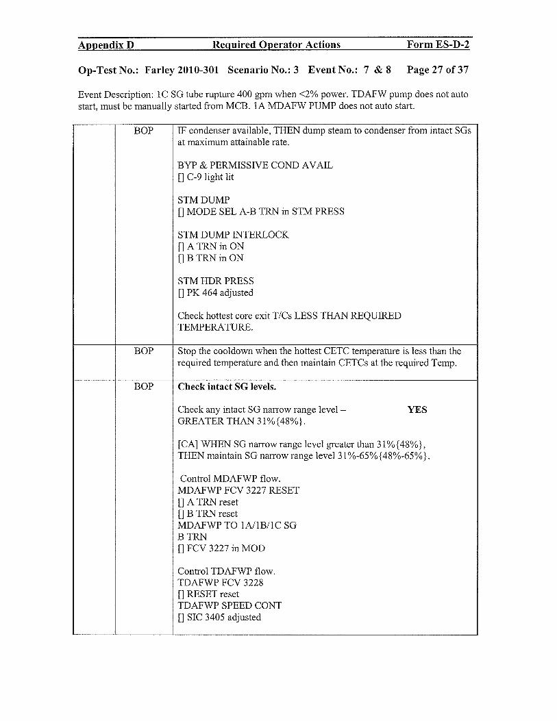
Appendix B Required Operator Actions Form ES-D-2
Op-Test No.: Farley 2010-301 Scenario No.: 3 Event No.: 7 & 8 Page 27 of 37
Event Description: 1C SG tube rupture 400 gpm when <2% power. TDAFW pump does not autostart, must be manually started from MCB. 1A MDAFW PUMP does not auto start.
BOP IF condenser available, THEN dump steam to condenser from intact SGsat maximum attainable rate.
BYP & PERMISSIVE CONI) AVAIL[]C-9 light lit
STM DUMP[]MODE SEL A-B TRN in STM PRESS
STM DUMP INTERLOCK
[] A TRN in ON
[1 B TRN in ON
STM HDR PRESS[]PK 464 adjusted
Check hottest core exit T/Cs LESS THAN REQUIREDTEMPERATURE.
BOP Stop the cooldown when the hottest CETC temperature is less than therequired temperature and then maintain CETCs at the required Temp.
BOP Check intact SG levels.
Check any intact SG narrow range level — YESGREATER THAN 31%{48%}.
[CA] WHEN SG narrow range level greater than 31% {48%},THEN maintain SG narrow range level 31%-65%{48%-65%}.
Control MDAFWP flow.MDAFWP FCV 3227 RESET[]A TRN reset[]B TRN resetMDAFWP TO 1AI1B/1C SGB TRN[]FCV 3227 in MOD
Control TDAFWP flow.TDAFWP FCV 3228[]RESET resetTDAFWP SPEED CONT[]SIC 3405 adjusted
Appendix D Required Operator Actions Form ES-D-2
Op-Test No.: Farley 2010-301 Scenario No.: 3 Event No.: 7 & 8 Page 27 of 37
Event Description: 1 C SG tube rupture 400 gpm when <2% power. TDAFW pump does not auto start, must be manually started from MCB. 1A MDAFW PUMP does not auto start.
BOP IF condenser available, THEN dump steam to condenser from intact SGs at maximum attainable rate.
BYP & PERMISSNE COND A V AIL [] C-9 light lit
STMDUMP [] MODE SEL A-B TRN in STM PRESS
STM DUMP INTERLOCK [] A TRNin ON [] B TRNin ON
STM HDR PRESS [] PK 464 adjusted
Check hottest core exit TICs LESS THAN REQUIRED TEMPERATURE.
BOP Stop the cooldown when the hottest CETC temperature is less than the required temperature and then maintain CETCs at the required Temp.
BOP Check intact SG levels.
Check any intact SG narrow range level - YES GREATER THAN 31%{48%}.
[CA] WHEN SG narrow range level greater than 31%{48%}, THEN maintain SG narrow range level 31 %-65% {48%-65%}.
Control MDAFWP flow. MDAFWP FCV 3227 RESET [] A TRN reset [] B TRN reset MDAFWP TO 1A/IBIl C SG BTRN [] FCV 3227 in MOD
Control TDAFWP flow. TDAFWP FCV 3228 [] RESET reset TDAFWP SPEED CONT [] SIC 3405 adjusted

Appendix D Required Operator Actions Form ES-D-2
Op-Test No.: Farley 2010-301 Scenario No.: 3 Event No.: 7 & 8 Page 28 of 37
Event Description: 1C SG tube rupture 400 gpm when <2% power. TDAFW pump does not autostart, must be manually started from MCB. 1A MDAFW PUMP does not auto start.
RO Check pressurizer PORVsCheck any PRZR PORV ISO — power available[CA] WHEN pressurizer pressure less than 2335 psig, THEN verify
pressurizer PORVs closed with no leakage.
Verify both PRZR PORVs - CLOSED
Check PRZR PORV temperature STABLE OR FALLING.[]PORV Temp TI-463
Check PRT parameters STABLE or FALLING.[1 PRT PRESS P1472[]PRT LVL LI-470[]PRT TEMP TI-471
Check at least one PRZR PORV ISO - OPEN
BOP Verify SI - RESET.MLB-1 1-1 not lit (A TRN) and MLB-1 1 1-1 not lit (B TRN)
Verify PHASE A CTMT ISO - RESET.MLB-2 1-1 not lit and MLB-2 1 1-1 not lit
BOP Check PHASE B CTMT ISO - RESET. - NO ctmt pressure increase
RO IF instrument air available, THEN establish instrument air tocontainment.
Verify at least one air compressor started.All{ COMPRESSOR[]1A[] lB[] 1CCheck INST AIR PRESS PT 4004B greater than 85 psig.
Check instrument air to containment.IA TO CTMT[] MLB-3 1-2 NOT litIA TO PENE RM PRESS LO[] Annunciator KD1 clear YES
Appendix D Required Operator Actions Form ES-D-2
Op-Test No.: Farley 2010-301 Scenario No.: 3 Event No.: 7 & 8 Page 28 of 37
Event Description: 1 C SG tube rupture 400 gpm when <2% power. TDAFW pump does not auto start, must be manually started from MCB. 1A MDAFW PUMP does not auto start.
RO Check pressurizer PORVs Check any PRZR PORV ISO - power available [CA] WHEN pressurizer pressure less than 2335 psig, THEN verify
pressurizer PORVs closed with no leakage.
Verify both PRZR PORVs - CLOSED
Check PRZR PORV temperature STABLE OR FALLING. [] PORV Temp TI-463
Check PRT parameters STABLE or FALLING. [] PRT PRESS PI 472 [] PRT LVL LI-470 [] PRT TEMP TI-471
Check at least one PRZR PORV ISO - OPEN
BOP Verify SI - RESET. MLB-1 1-1 not lit (A TRN) and MLB-1 11-1 not lit (B TRN)
Verify PHASE A CTMT ISO - RESET. MLB-2 1-1 not lit and MLB-2 11-1 not lit
BOP Check PHASE B CTMT ISO - RESET. - NO ctmt pressure increase
RO IF instrument air available, THEN establish instrument air to containment.
Verify at least one air compressor started. AIR COMPRESSOR []IA [] 1B [] lC Check INST AIR PRESS PI 4004B greater than 85 psig.
Check instrument air to containment. IA TOCTMT [] MLB-3 1-2 NOT lit IA TO PENE RM PRESS LO [] Annunciator KD 1 clear YES

Appendix D Required Operator Actions Form ES-D-2
Op-Test No.: Farley 2010-301 Scenario No.: 3 Event No.: 7 & 8 Page 29 of 37
Event Description: 1C SG tube rupture 400 gpm when <2% power. TDAFW pump does not autostart, must be manually started from MCB. 1A MDAFW PUMP does not auto start.
RO [CA] Check if LHSI Pumps should be stopped.Check RCS pressure — GREATER THAN 275 psig{435 psig} YESPT-402 AND 403Check RCS pressure - STABLE OR RISING YES
Verify the SI reset
Secure any running RHR pumps Take HS to stop.
SRO Check if Cooldown should be stopped.
Check hottest core exit T/Cs - LESS THAN REQUIRED Temperature.
Stop RCS cooldownMaintain core exit T/Cs — LESS THAN REQUIRED TEMPERATURE.RNODo NOT proceed until hottest core exit T/Cs - LESS THAN REQUIREDTEMPERATURE.
SRO o Check ruptured SG(s) pressure - STABLE OR RISING.
o Check SUB COOLED MARGIN MONITOR indication -
GREATER THAN 36°F{65°F} SUBCOOLED IN CETCMODE.
YES for BOTH
Appendix D Required Operator Actions Form ES-D-2
Op-Test No.: Farley 2010-301 Scenario No.: 3 Event No.: 7 & 8 Page 29 of 37
Event Description: IC SG tube rupture 400 gpm when <2% power. TDAFW pump does not auto start, must be manually started from MCB. IA MDAFW PUMP does not auto start.
RO [CAl Check ifLHSI Pumps should be stopped. Check RCS pressure - GREATER THAN 275 psig{435 psig} YES PT -402 AND 403 Check RCS pressure - STABLE OR RISING YES
Verify the SI reset
Secure any running RHR pumps Take HS to stop.
SRO Check if Cooldown should be stopped.
Check hottest core exit TICs - LESS THAN REQUIRED Temperature.
Stop RCS cooldown Maintain core exit TICs - LESS THAN REQUIRED TEMPERATURE. RNO Do NOT proceed until hottest core exit TICs - LESS THAN REQUIRED TEMPERATURE.
SRO 0 Check ruptured SG(s) pressure - STABLE OR RISING.
o Check SUB COOLED MARGIN MONITOR indication -GREATER THAN 36°F{65°F} SUBCOOLED IN CETC MODE.
YES for BOTH

Appendix D Required Operator Actions Form ES-D-2
Op-Test No.: Farley 2010-301 Scenario No.: 3 Event No.: 7 & 8 Page 30 of 37
Event Description: 1C SG tube rupture 400 gpm when <2% power. TDAFW pump does not autostart, must be manually started from MCB. IA MDAFW PUMP does not auto start.
NOTE: Normal pressurizer spray may become ineffective during pressure reduction. Thissituation justifies using a PRZR PORV per step 18.
(CT) RO Critical TaskReduce RCS pressure to minimize break flow and refill pressurizer.Open all available normal pressurizer spray valves.1A(1B) LOOP SPRAY VLV
[]PK 444C
[1 PK 444D Not available due to RCP tripped
Reduce RCS pressure using ONE pressurizer PORV to minimize breakflow and refill pressurizer.One PORV may be used to increase the pressure reduction and willprobably be the case.
SRO Reduce RCS pressure until one of the following three conditions occurs,then stop RCS pressure reduction.RCS pressure less than ruptured SG pressureANDpressurizer level greater than l3%{43%}ORPressurizer level greater than 73%{66%}ORSCMM indication less than 16°F{45°F} subcooled in CETC mode.
Then verify the sprays and PORVs are closed.
SRO Check RCS pressure - RISING.P1-402 and 403 rising
Evaluate SI termination criteriao Check SUB COOLED MARGIN MONITOR indication —
GREATER THAN 16°F{45°F} SUBCOOLED IN CETCMODE.
o Check secondary heat sink available.>395 gpmAFW flow> 31%{48%} SGNR level
o Check RCS pressure - STABLE OR RISINGo Check pressurizer level GREATER THAN 13% {43% }.
Suggested END OF SCENARIO
Appendix D Required Operator Actions Form ES-D-2
Op-TestNo.: Farley2010-301 ScenarioNo.:3 Event No.: 7 &8 Page30of37
Event Description: 1 C SG tube rupture 400 gpm when <2% power. TDAFW pump does not auto start, must be manually started from MCB. lA MDAFW PUMP does not auto start.
NOTE: Normal pressurizer spray may become ineffective during pressure reduction. This situation justifies using a PRZR PORV per step 18.
(CT) RO Critical Task Reduce RCS pressure to minimize break flow and refill pressurizer. Open all available normal pressurizer spray valves. 1A(lB) LOOP SPRAY VLV
[] PK 444C [] PK 444D Not available due to RCP tripped
Reduce RCS pressure using ONE pressurizer PORV to minimize break flow and refill pressurizer. One PORV may be used to increase the pressure reduction and will probably be the case.
SRO Reduce RCS pressure until one of the following three conditions occurs, then stop RCS pressure reduction. RCS pressure less than ruptured SG pressure AND pressurizer level greater than 13%{43%} OR Pressurizer level greater than 73%{66%} OR
SCMM indication less than 16°P {45°P} subcooled in CETC mode.
Then verify the sprays and PORVs are closed.
SRO Check RCS pressure - RISING. PI-402 and 403 rising
Evaluate SI termination criteria o Check SUB COOLED MARGIN MONITOR indication -
GREATER THAN 16°P {45°P} SUB COOLED IN CETC MODE.
o Check secondary heat sink available. >395 gpm AFW flow > 31 %{48%} SGNR level
o Check RCS pressure - STABLE OR RISING o Check pressurizer level GREATER THAN 13%{43%}.
Suggested END OF SCENARIO

Appendix D Required Operator Actions Form ES-D-2
Op-Test No.: Farley 2010-301 Scenario No.: 3 Event No.: Page 31 of 37
Event Description: Attachment 2 and 4 of EEP-O
Cue: BOP will accomplish when at step 5 of EEP-O
Time Position Applicant’s Action or Behavior
Attachment 2 of EEP-O
AUTOMATIC ACTIONS VERIFICATION
1 Verify each SW train - HAS TWO SW PUMPs STARTED.BOP [] A train(1A,1B or 1C)
[1 B train (1D,1E or 1C)
2 Verify each train of CCW - STARTED.2.1 Verify one CCW PUMP in each train- STARTED.Attain HX 1C or lB CCW FLOW
[j FT 3043CA > 0 gpmOR[] FT 3043BA > 0 gpmBtrainHXlAor lBCCW FLOW
[] FT 3043AA> 0 gpmOR
[] FT 3043BA > 0 gpm
Verify SW flow to associated CCW HX’sSW FROM 1A(1B, 1C) CCW HX
[j Q1PT6FI3009AA >0 gpm
[] Q1P16FI3009BA> 0 gpm
[] Q1P16FI3009CA> 0 gpm
Verify one CHG PUMP in each train - STARTED.
[] A train(1A or 1B) amps> 0
BOP []Btrain(lCorlB)amps>0
BOP Verify REIR PUMPs - STARTED.
RHR PUMP
[] 1A amps > 0
[] lB amps > 0
BOP Verify Safety Injection Flow.
Check HHSI flow - GREATER THAN 0 gpm.
[] Fl 943
BOP Check RCS pressure - LESS THAN 275 psig{435 psig}. NO
Appendix D Required Operator Actions Form ES-D-2
Op-Test No.: Farley 2010-301 Scenario No.: 3 Event No.: Page 31 of 37
Event Description: Attachment 2 and 4 of EEP-O
Cue: BOP will accomplish when at step 5 of EEP-O
Time Position Applicant's Action or Behavior
Attachment 2 of EEP-O
AUTOMATIC ACTIONS VERIFICATION
1 Verify each SW train - HAS TWO SW PUMPs STARTED. BOP [] A train (IA,lB or lC)
[] B train (lD,lE or lC)
2 Verify each train ofCCW - STARTED. 2.1 Verify one CCW PUMP in each train- STARTED. A train HX 1 C or lB CCW FLOW [] FI 3043CA > 0 gpm OR [] FI 3043BA > 0 gpm B train HX lA or lB CCWFLOW [] FI 3043AA > 0 gpm OR [] FI 3043BA > 0 gpm
Verify SW flow to associated CCW HX's SW FROM lA(lB, lC) CCW HX [] QIPI6FI3009AA > 0 gpm [] QIPI6FI3009BA > 0 gpm [] QIPI6FI3009CA > 0 gpm
Verify one CHG PUMP in each train - STARTED.
[] A train (IA or lB) amps> 0
BOP [] B train (lC or lB) amps> 0
BOP Verify RHR PUMPs - STARTED.
RHRPUMP
[] lA amps> 0
[] lB amps> 0
BOP Verify Safety Injection Flow.
Check HHSI flow - GREATER THAN 0 gpm.
[] FI 943
BOP Check RCS pressure - LESS THAN 275 psig{435 psig}. NO

Appendix D Required Operator Actions Form ES-D-2
Op-Test No.: Fancy 2010-301 Scenario No.: 3 Event No.: Page 32 of 37
Event Description: Attachment 2 and 4 of EEP-O
BOP 6 Verify containment ventilation isolation.
6.1 Verify containment purge dampers - CLOSED.
[] 3197
[] 3198D
[] 3198C
[] 3196
[] 3198A
[] 3198B
6.2 Verify containment mini purge dampers - CLOSED.
CTMT PURGE DMPRS
MINI-2866C & 2867C
FULL
[] 2867D
6.3 Stop MINI PURGE SUPP/EXH FAN. Will place HS toSTOP
BOP 7 Verify containment fan cooler alignment.
7.1 Verify at least one containment fan cooler per train - STARTED IN SLOWSPEED.
CTMT CLR FAN SLOW SPEED
LI A train
[]1A
{] lB
LI B train
[j 1C
[j 1D
7.2 Verify associated emergency service water outlet valves - OPEN.
EMERG SW FROM 1A(1B,1C,1D) CTMT CLR
{] Q1P16MOV3O24A
[] Q1P16MOV3O24B
[] Q1P16MOV3O24C
[] Q 1P 1 6MOV3024D
Appendix D Required Operator Actions Form ES-D-2
Op-Test No.: Farley 2010-301 Scenario No.: 3 Event No.: Page 32 of37
Event Description: Attachment 2 and 4 ofEEP-O
BOP 6 Verify containment ventilation isolation.
6.1 Verify containment purge dampers - CLOSED.
[]3197
[] 3198D
[]3198C
[] 3196
[]3198A
[] 3198B
6.2 Verify containment mini purge dampers - CLOSED.
CTMT PURGE DMPRS
MINI-2866C & 2867C
FULL-
[] 2867D
6.3 Stop MINI PURGE SUPP/EXH FAN. Will place HS to STOP
BOP 7 Verify containment fan cooler alignment.
7.1 Verify at least one containment fan cooler per train - STARTED IN SLOW SPEED.
CTMT CLR FAN SLOW SPEED
[J A train
[] 1A
[]1B
DB train
[]1C
[]ID
7.2 Verify associated emergency service water outlet valves - OPEN.
EMERG SW FROM 1A(lB,lC,ID) CTMT CLR
[] Q1P16MOV3024A
[] Q1P16MOV3024B
[] Q1P16MOV3024C
[] Q1P16MOV3024D

Appendix B Required Operator Actions Form ES-D-2
Op-Test No.: Farley 2010-301 Scenario No.: 3 Event No.: Page 33 of 37
Event Description: Attachment 2 and 4 of EEP-O
BOP 8 Verity AFW Pumps - STARTED.
8.1 Verify both MDAFW Pumps - STARTED these do notauto start in scenario
[] 1A MDAFW Pump amps >0
[] lB MDAFW Pump amps > 0
AND
[] FI-3229A indicates > 0 gpm
[] FI-3229B indicates > 0 gpm
[] FI-3229C indicates > 0 gpm
8.2 Check TDAFW Pump start required.
LI Condition L]TSLB LI Setpoint [I Coincidence LI
RCP Bus TSLB2 1-1 L12680 V 1/2 Detectors
Undervoltage 1-2 1-3 on 2/3 Busses
Low Low SG TSLB4 28% 2/3 Detectors
Water Level 4-1,4-2,4-3 on 2/3 SGs
In Any 5-1,5-2,5-3
2/3 SGs 6-1,6-2,6-3
BOP 8.3 Verify TDAFWP started.
[] MLB-4 1-3 lit
[] MLB-4 2-3 lit[] MLB-4 3-3 lit
TDAFWP SPEED[] S13411A>3900rpm
TDAFWP SPEED CONT
[] SIC 3405 adjusted to 100%
8.4 Verify TDAFW flow path to each SG.TDAFWP TO 1A(1B,1C) SG[] Q1N23HV3228A in MOD{] Q1N23HV3228B in MOD[] Q1N23HV3228C in MOD
TDAFWP TO 1A(1B,1C) SO FLOW CONT[] HIC 3228AA open[] HIC 3228BA open[] HIC 3228CA open
Appendix D Required Operator Actions Form ES-D-2
Op-Test No.: Farley 2010-301 Scenario No.: 3 Event No.: Page 33 of37
Event Description: Attachment 2 and 4 ofEEP-O
BOP 8 Verify AFW Pumps - STARTED.
8.1 Verify both MDAFW Pumps - STARTED these do not auto start in scenario
[] 1A MDAFW Pump amps> 0
[] lB MDAFW Pump amps> 0
AND
[] FI-3229A indicates> 0 gpm
[] FI-3229B indicates> 0 gpm
[] FI-3229C indicates> 0 gpm
8.2 Check TDAFW Pump start required.
o Condition OTSLB I]Semoint o Coincidence 0
RCP Bus TSLB21-1 02680 V 112 Detectors
Undervoltage 1-2 1-3 on 2/3 Busses
LowLowSG TSLB4 28% 2/3 Detectors
Water Level 4-1,4-2,4-3 on 2/3 SGs
In Any 5-1,5-2,5-3
2/3 SGs 6-1,6-2,6-3
BOP 8.3 Verify TDAFWP started. [] MLB-4 1-3 lit [] MLB-4 2-3 lit [] MLB-4 3-3 lit
TDAFWP SPEED [] SI 3411A > 3900 rpm
TDAFWP SPEED CONT [] SIC 3405 adjusted to 100%
8.4 Verify TDAFW flow path to each SG. TDAFWP TO 1A(lB,1C) SG [] Q1N23HV3228A in MOD [] Q1N23HV3228B in MOD [] Q1N23HV3228C in MOD
TDAFWP TO 1A(1B,1C) SG FLOW CONT [] HIC 3228AA open [] HIC 3228BA open [] HIC 3228CA open

Appendix D Required Operator Actions Form ES-D-2
Op-Test No.: Farley 2010-301 Scenario No.: 3 Event No.: Page 34 of 37
Event Description: Attachment 2 and 4 of EEP-O
BOP9 Verify main feedwater status.9.1 Verify main feedwater flow control and bypass valves - CLOSED.1A(1B,1C) SG FW FLOW[]FCV 478{]FCV 488[]FCV 498
9.2 Verify both SGFPs - TRIPPED.
9.3 Verify SG blowdown - ISOLATED.1A(1B,1C) SGBD ISO
[] Q1G24HV7614A closed
[j Q1G24HV7614B closed
[j Q1G24HV7614C closed
9.4 Verify SG blowdown sample - ISOLATED MLB lights lit.1A(1B,1C) SGBD SAMPLE STEAM GEN ISO
[] MLB1 19-2 lit Q1P15HV3328 closed
[] MLB1 19-3 lit Q1P15HV3329 closed
[] MLB1 19-4 lit Q1P15HV3330 closed
BOP 10 Check no main steam line isolation actuation signal present.
Signal Setpoint coincidence TSLB
LO SG PRESS < 585 psig 2/3 TSLB4 19-2,3,4
Hi stm flow >40% V2 on 2/3 TSLB4 16-3,4
and and 17-3,4 18-3,4
Lo-Lo Tavg <543°F 2/3 TSLB2 10-1,2,3
HI-HI ctmt press >16.2 psig 2/3 TSLB1 2-2,3,4
11 Verify PHASE A CTMT ISO. NO- actuate handswitch
11.1 Verify PHASE A CTMT ISO - ACTUATED.
[] MLB-2 1-1 lit
BOP [] MLB-2 11-1 lit
11.2 Check all MLB-2 lights - LIT. 11.2 Verify PHASE A CTMTISO alignment using ATTACH 3, PHASEACTMT ISO
AppendixD Required Operator Actions Form ES-D-2
Op-Test No.: Farley 2010-301 Scenario No.: 3 Event No.: Page 34 of37
Event Description: Attachment 2 and 4 ofEEP-O
BOP 9 Verify main feedwater status. 9.1 Verify main feedwater flow control and bypass valves - CLOSED. lA(lB,lC) SG FW FLOW [] FCV 478 [] FCV 488 [] FCV 498
9.2 Verify both SGFPs - TRIPPED.
9.3 Verify SG blowdown - ISOLATED. lA(1B,IC) SGBD ISO [] QIG24HV7614A closed [] QIG24HV7614B closed [] QIG24HV7614C closed
9.4 Verify SG blowdown sample - ISOLATED MLB lights lit. lA(lB,lC) SGBD SAMPLE STEAM GEN ISO [] MLBI 19-2 lit QIP15HV3328 closed [] MLBI 19-3 lit QIP15HV3329 closed [] MLBI 19-4 lit QIP15HV3330 closed
BOP 10 Check no main steam line isolation actuation signal present.
Signal Semoint coincidence TSLB
LO SGPRESS < 585 psig 2/3 TSLB4 19-2,3,4
Hi strn flow >40% ~ on 2/3 TSLB416-3,4
and and 17-3,4 18-3,4
Lo-Lo Tavg <543°F 2/3 TSLB2 10-1,2,3
HI-HI ctrnt press >16.2 psig 2/3 TSLB 1 2-2,3,4
11 Verify PHASE A CTMT ISO. NO- actuate handswitch
11.1 Verify PHASE A CTMT ISO - ACTUATED.
[] MLB-2 1-1 lit
BOP [] MLB-2 11-1 lit
11.2 Check all MLB-2 lights - LIT. 11.2 Verify PHASE A CTMT ISO alignment using ATTACH 3, PHASE ACTMT ISO

Appendix D Required Operator Actions Form ES-D-2
Op-Test No.: Farley 2010-301 Scenario No.: 3 Event No.: Page 35 of 37
Event Description: Attachment 2 and 4 of EEP-O
BOP 12 Check all reactor trip and 12 Perform the following.reactor trip bypass breakers - OPEN. 12.1 Open reactor trip
breaker(s) manually from MCBor locally.
Reactor trip breaker A 12.2 Record any breaker(s) Reactortrip breaker B manually opened.Reactor trip bypass breaker AReactor trip bypass breaker B
BOP 13 Trip CRDM MG set supply breakers.
1A(1B) MG SET SUPP BKR
[] N1C11EOO5A
[] N1C11EOO5B
BOP14 Secure secondary components.14.1 Stop both heater drain pumps.HDP[J1A
[] lB
14.2 Check any condensate pump started.
14.2.1 IF started, THEN stop all but one condensate pump.[hA[] lB
If NO condensate pumps are started then place all HSs to STOP
14.3 IF condensate pump operating, THEN verify backup cooling aligned tocondensate pumps per SOP-O.O, APPENDIX B, TB SO ACTIONSFOLLOWING A REACTOR TRIP OR SAFETY INJECTION.
Will call TBSO to accomplish this.
BOP 15 Verify both CRACS mode selector switches in the ON position.
CRACS Mode Selector Switch
[j A TRAIN
[] B TRAIN
Will call BOOTH to have this accomplished since this is not in thesimulator
Appendix D Required Operator Actions Form ES-D-2
Op-Test No.: Farley 2010-301 Scenario No.: 3 Event No.: Page 35 of37
Event Description: Attachment 2 and 4 ofEEP-O
BOP 12 Check all reactor trip and 12 Perform the following. reactor trip bypass breakers - OPEN. 12.1 Open reactor trip
breaker(s) manually fromMCB or locally.
Reactor trip breaker A 12.2 Record any breaker(s) Reactor trip breaker B manually opened. Reactor trip bypass breaker A Reactor trip bypass breaker B
BOP 13 Trip CRDM MG set supply breakers.
IA(1B) MG SET SUPP BKR
[] NICIIEOO5A
[] NICIIEOO5B
BOP 14 Secure secondary components. 14.1 Stop both heater drain pumps. HDP []1A []1B
14.2 Check any condensate pump started.
14.2.1 IF started, THEN stop all but one condensate pump. []1A [] 1B
If NO condensate pumps are started then place all HSs to STOP
14.3 IF condensate pump operating, THEN verify backup cooling aligned to condensate pumps per SOP-O.O, APPENDIX B, TB SO ACTIONS FOLLOWING A REACTOR TRIP OR SAFETY INJECTION.
Will call TBSO to accomplish this.
BOP 15 Verify both CRACS mode selector switches in the ON position.
CRACS Mode Selector Switch
[] A TRAIN
[] B TRAIN
Will call BOOTH to have this accomplished since this is not in the simulator

Appendix D Required Operator Actions Form ES-D-2
Op-Test No.: Farley 2010-301 Scenario No.: 3 Event No.: Page 36 of 37
Event Description: Attachment 2 and 4 of EEP-0
BOP 16 WHEN at least 30 seconds have passed since turbine trip,
THEN check main generator tripped.
23OKVBKR
[] 810- OPEN
[] 914 - OPEN
BOP 17 Verify two trains of ECCS equipment aligned.
17.1 Perform ATTACHMENT 4, TWO TRAiN ECCS ALIGNMENT
VERIFICATION.
End of Attachment 2
Appendix D Required Operator Actions Form ES-D-2
Op-Test No.: Farley 2010-301 Scenario No.: 3 Event No.: Page 36 of37
Event Description: Attachment 2 and 4 ofEEP-O
BOP 16 WHEN at least 30 seconds have passed since turbine trip,
THEN check main generator tripped.
230 KV BKR
[] 810 - OPEN
[] 914 - OPEN
BOP 17 Verify two trains of ECCS equipment aligned.
17.1 Perform ATTACHMENT 4, TWO TRAIN ECCS ALIGNMENT
VERIFICATION.
End of Attachment 2

Appendix D Required Operator Actions Form ES-D-2
Op-Test No.: Farley 2010-301 Scenario No.: 3 Event No.: Page 37 of 37
Event Description: Attachment 2 and 4 of EEP-O
Attachment 4TWO TRAIN ECCS ALIGNMENT VERIFICATION
BOP 1 Verify two trains of ECCS equipment aligned.Check DFO 1 closedVerify DFO2 closedCheck DG15 closedVerify DGO2 closed
Verify two trains of battery chargers — energized- Amps>O
1.6 Verify two trains of ESF equipment aligned.
Check all MLB-l lights LITVerify charging pump suction and discharge valves - OPEN.
CHG PUMP DISCH HDR ISO[jQ1E21MOV8132A
[j Q1E21MOV8132B[]Q1E21MOV8133A[]Q1E21MOV8133BCHG PUMP SUCTION HDR ISO[]Q1E21MOV8I3OA[]Q1E21MOV813OB[]Q1E21MOV8131A
[1 Q1E21MOV8 13 lB
1.7 Verify all post accident containment air mixing systemfans - STARTED. (BOP)
POST ACCIDENT MIXTNG FAN[]1A[]1B[J 1C[]1DRX CAV H2 DILUTION FAN[]1A[]1B
BOP Call Radside SO to Verify Spent Fuel Pool Cooling in service per SOP-54.O,SPENT FUEL PIT COOLiNG AND PURIFICATION SYSTEM.
End of Attachment 4
Appendix D Required Operator Actions Form ES-D-2
Op-Test No.: Farley 2010-301 Scenario No.: 3 Event No.: Page 37 of37
Event Description: Attachment 2 and 4 of EEP-O
Attachment 4 TWO TRAIN ECCS ALIGNMENT VERIFICATION
BOP 1 Verify two trains of ECCS equipment aligned. Check DFOI closed Verify DF02 closed Check DG 15 closed Verify DG02 closed
Verify two trains of battery chargers - energized - Amps>O
1.6 Verify two trains of ESF equipment aligned.
Check all MLB-l lights LIT Verify charging pump suction and discharge valves - OPEN.
CHG PUMP DISCH HDR ISO [] QIE21MOV8132A [] QIE21MOV8132B [] QIE21MOV8133A [] QIE21MOV8133B CHG PUMP SUCTION HDR ISO [] QIE21MOV8130A [] QIE21MOV8130B [] QIE21MOV8131A [] QIE21MOV8131B
1.7 Verify all post accident containment air mixing system fans - STARTED. (BOP)
POST ACCIDENT MIXING FAN []1A [] 1B []1C [] 1D RX CA V H2 DILUTION FAN []1A []1B
BOP ~all Radside SO to Verify Spent Fuel Pool Cooling in service per SOP-54.0, SPENT FUEL PIT COOLING AND PURIFICA nON SYSTEM.
End of Attachment 4

Appendix D Crew Briefing sheet Form ES-D-2
Op-Test No.: FA2O1O-301Page 1 of2
Brief
This simulator performance scenario is performed in the EVALUATION MODE. You
should not direct questions to the evaluators. Otherwise, you should perform as if you were
in the MCR.
Your ability to maintain a log is not being graded, but maintaining a rough log is
recommended to help during briefs.
If you need to communicate with the Unit 2 operator, verbally state, “Unit 2” and an
instructor will locate to the Unit 2 area and respond to you as quickly as possible.
If you need to communicate with the Shift Manger, use the PAX phone to call if during
normal operations. If in the EOPs, then turn to the glass and address the SM for updates and
other information purposes. If you need an action done, call the SM or SSS on the phone.
In the unlikely event that the simulator fails such that illogical indications result, the session
will be terminated. In other words, respond to what you see. If there is a problem with the
simulation, the session will be terminated or adjusted as appropriate based on the specific
problem.
Assign operating positions.
Ask for and answer questions.
Appendix D Crew Briefing sheet Form ES-D-2
Op-Test No.: FA2010-301 Page 1 of2
This simulator performance scenario is performed in the EV ALUA nON MODE. You
should not direct questions to the evaluators. Otherwise, you should perform as if you were
in the MeR.
Your ability to maintain a log is not being graded, but maintaining a rough log IS
recommended to help during briefs.
If you need to communicate with the Unit 2 operator, verbally state, "Unit 2" and an
instructor will locate to the Unit 2 area and respond to you as quickly as possible.
If you need to communicate with the Shift: Manger, use the PAX phone to call if during
normal operations. If in the EOPs, then tum to the glass and address the SM for updates and
other information purposes. If you need an action done, call the SM or SSS on the phone.
In the unlikely event that the simulator fails such that illogical indications result, the session
will be terminated. In other words, respond to what you see. If there is a problem with the
simulation, the session will be terminated or adjusted as appropriate based on the specific
problem.
Assign operating positions.
Ask for and answer questions.

Appendix D Turnover sheet Form ES-D-2
[Xl Unit I [ ] Unit 2 Shift: DateOff-going SS Oncoming SS [ j N [ Xj D Today
Part I — To be reviewed by the oncoming Supervisor prior to assuming the shift.
Security Keys A, 5, D, SW, X on key ring. SS
Unit Mode 1, 25% RTP, MOL, 1292 ppm Cb, 10,000 MWD/MTU, Xe is building in from a xenon free startup atStatus 80 pcm/hr
Rod control is in Manual. Continue the ramp up to 50% power.UOP-3.1, v.104, step 5.1.1. UOP-1.2 v94 is still in progress at step 5.74, transferring control from the Bypass
FRVs to the Main FRVs.
STPslEvolutionsSTP-27 I due in 3hours10_; 109.1 Noadi.
Status of Special Testing
General Information1. Current Risk Assessment is YELLOW and projected is YELLOW2. Bypass FRVs are in Auto and the Main FRVs are in manual control and partially open.3. 1 B DIG is tagged out. The tagging order is being prepared for RTS in the next hour.4. lB MDAFW pump is tagged out for bearing replacement. (OOS 6 hrs, ETR 2 hrs)5. Ramp on hold for turnover.6. Severe thunderstorm warnings in effect for Southeast Alabama & Western Georgia.7.8.9.10.Equipment Status1 B DG is tagged out Maintain VCT gas pressure 25-30 psiglB MDAFW pump is tagged out
No New Night OrdersPart II Review Shift Complement
LCOs Reviewed SS (initials) reviewed as early in shift as possiblePart III: STP-1.0 Operator Logs Cond. Report Autolog ELDS & GEN Keys
Reviewed/Signed Reviewed Queue Reviewed Spreadsheet TurnedReviewed verified Over
[X]Yes [X]Yes [X]Yes [X]Yes [X]Yes [XjYes
RéctiyityPlait ‘vvaste, anagement statusLast shift was diluting 40 gal every 5 minutes while #3 RHT — On Serviceramping
WGS — securedLCO StatusLCO 3.8.1 condition B, STP-27.1 completed 3 hours agoLCO 3.7.5 condition BNiaht Orders
FA2O1 0-301
Appendix D Turnover sheet Form ES-D-2
Unit 2 Shift: Date Oncoming SS [ 1 N [X 1 D Today
Part 1- To be reviewed by the oncoming Supervisor prior to assuming the shift.
Security Keys A, S, 0, SW, X on key ring.~
Unit Mode 1, 25% RTP, MOL, 1292 ppm Cb, 10,000 MWO/MTU, Xe is building in from a xenon free startup at Status 80 pcm/hr
Rod control is in Manual. Continue the ramp up to 50% power. UOP-3.1, v.l04, step 5.1.1. UOP-1.2 v94 is still in progress at step 5.74, transferring control from the Bypass
FRVs to the Main FRVs .
• $.IPs/.EY~14.tion~: i~m·~i~7:,;~<qH~ .. il):~ .. "·. hours
. ATrainOn-Service -::A Train Protected· . - . . .
1 .0_; 109.1 _----'--'=-'=
:\General/lflfo.rrnation·r· 1. Current Risk Assessment is YELLOW and projected is YELLOW 2. Bypass FRVs are in Auto and the Main FRVs are in manual control and partially open. 3. 1 B DIG is tagged out. The tagging order is being prepared for RTS in the next hour. 4. 1 B MDAFW pump is tagged out for bearing replacement. (OOS 6 hrs, ETR 2 hrs) 5. Ramp on hold for turnover. 6. Severe thunderstorm warnings in effect for Southeast Alabama & Western Georgia. 7. 8. 9. 10.
. .. ··.Waste.Mallael11ent Status· #3 RHT - On Service
ram in
Review Shift Complement LCOs Reviewed SS (initials) reviewed as early in shift as possible
Part III: STP-1.0 Operator Logs Condo Report Autolog ELOS & GEN Reviewed/Signed Reviewed Queue Reviewed Spreadsheet
Reviewed verified [ X 1 Yes [ X 1 Yes [ X 1 Yes [ X 1 Yes [ X 1 Yes
FA2010-301
Keys Turned Over
[X 1 Yes

Appendix D Scenario 4 Outline Form ES-D-1
Facility: Farley Scenario No.: _j... Op-Test No.: FA2O1 0301
Examiners: Operators:
Initial Conditions: 4% RTP, EOL, B train o/s, B train protected, 528 ppm Cb, 18,000 MWD,Xe building in
Turnover:• There are no LCOs preventing mode I entry. A risk assessment has been performed and
the decision has been made to startup as planned.• Increase Reactor power to 12% in preparation of starting the Main Turbine.• Current Risk Assessment is GREEN and projected to remain GREEN• Plant start-up is on hold for turnover and will recommence after turnover.• 1A SGFP is on service, transfer to main feed main feed bypass valves is complete.• UOP-1 .2 is complete up to step 5.55.• IC DIG in process of being returned from maintenance condition. LCO 3.8.1 (IC DG)• STP-27.1 in progress on both units. Surveillance is due again in 3 hours.• Severe thunderstorm warnings in effect for Southeast Alabama & Western Georgia.
Event Malf Event EventNo. No. Type* Description
I R (RO) Commence Ramp up from 4% to 12% power.2 1 C (BOP) FK-499 failure high Auto output failure3 2 1 (RO) LT-459 fails HIGH, controlling Pressurizer level channel,
TS (SRO) charging in man required.TS 3.3.1
4 3 I (BOP) PT-464 fails high, Steam Header Pressure, Steam dumpsopen until shut by P-12, SGFP speed increases, Manualcontrol required
5 TS (SRO) An RCS 75 GPM (with a 20 second ramp) leak on 1A4 C (RO) RCS loop develops TS 3.4.13 Cond ATrg I Unit 2 will experience a safety injection at step 1 of AOP
I. This ensures I-2A DG will align to Unit 2 when theLOSP occurs and Unit 1 will experience a loss of all ACcondition. (no action by crew required)
6 M (ALL) The control system for the “A” loop spray valve (PCV444C) fails. The spray valve sticks open. Man Rx TripRequired.
7 M (ALL) After ESP-0. I entry, Dual unit LOSP ECP-0.0, Loss of AllAC Power, entry required.
5 C(BOP) 1 B DG fails to auto start, 2C or I B DG must be started.8 M (ALL) LB LOCA occurs after second return to ESP-0.1 after
LOSP.9 6 C High Head Safety Injection (HHSI) MOVs 8803A & B also
(BOP/RO) fail to open.
Farley April exam Scenario 4 Page 1 of 6
Appendix D Scenario 4 Outline Form ES-D-1
Facility: Farley Scenario No.: ~ Op-Test No.: FA2010301
Examiners: Operators:
Initial Conditions: 4% RTP, EOL, B train ols, B train I2rotected, 528 I2l2m Cb, 18,000 MWD, Xe building in
Turnover:
• There are no LCOs preventing mode 1 entry. A risk assessment has been performed and the decision has been made to startup as planned.
• Increase Reactor power to 1.eparation of starting the Main Turbine.
• Current Risk Assessment is ..• and projected to remain
• Plant start-up is on hold for turnover and will recommence after turnover.
• 1A SGFP is on service, transfer to main feed main feed bypass valves is complete.
• UOP-1.2 is complete up to step 5.55.
• 1C DIG in process of being returned from maintenance condition. LCO 3.8.1 (1C DG)
• STP-27.1 in progress on both units. Surveillance is due again in 3 hours.
• Severe thunderstorm warnings in effect for Southeast Alabama & Western Georgia.
Event Malf Event Event No. No. Type* Description
1 R (RO) Commence Ramp up from 4% to 12% power. 2 1 C (BOP) FK-499 failure high Auto output failure 3 2 I (RO) L T -459 fails HIGH, contrOlling Pressurizer level channel,
TS (SRO) charging in man required. TS 3.3.1
4 3 I (BOP) PT-464 fails high, Steam Header Pressure, Steam dumps open until shut by P-12, SGFP speed increases, Manual control required
5 TS (SRO) An RCS 75 GPM (with a 20 second ramp) leak on 1A 4 C (RO) RCS loop develops TS 3.4.13 Cond A Trg 1 Unit 2 will experience a safety injection at step 1 of AOP-
1. This ensures 1-2A DG will align to Unit 2 when the LOSP occurs and Unit 1 will experience a loss of all AC condition. (no action by crew required)
6 M (ALL) The control system for the "A" loop spray valve (PCV-444C) fails. The spray valve sticks open. Man Rx Trip Required.
7 M (ALL) After ESP-0.1 entry, Dual unit LOSP ECP-O.O, Loss of All AC Power, entry required.
5 C(BOP) 1 B DG fails to auto start, 2C or 1 B DG must be started. 8 M (ALL) LB LOCA occurs after second return to ESP-0.1 after
LOSP. 9 6 C High Head Safety Injection (HHSI) MOVs 8803A & B also
(BOP/RO) fail to open.
Farley April exam Scenario 4 Page 1 of6

Appendix D Scenario 4 Outline Form ES-D-1
10 7 C(BOP) 8820B does not auto openIA CS pump does not auto startSelected B train ctmt cooler does not auto start
11 8 C(RO) TDAFW Pump auto start failure
*(N)ormal (R)eactivity, (l)nstrument, (C)omponent, (TS)Tech Spec, (M)ajor
Farley April exam Scenario 4 Page 2 of 6
Appendix 0 Scenario 4 Outline Form ES-D-1
10 7 C(BOP) 8820B does not auto open 1A CS pump does not auto start Selected B train ctmt cooler does not auto start
11 8 C(RO) TDAFW Pump auto start failure
*(N)ormal, (R)eactivity, (I)nstrument, (C)omponent, (TS)Tech Spec, (M)ajor
Farley April exam Scenario 4 Page 2 of6

Appendix D Scenario 4 Outline Form ES-D-1
Eye Maif. No. Event Eventnt Type* DescriptionN0.
PRESETSo IC- 48 ------- 4% EOL B train o/s with A SGFP O/S, 528
ppm Cb, 18,000 MWD, Xe building in0 MAL I D / imf mal-dsgOO4 IC DG air start light failed OFF
0 CMFmalf I imf cbkrxtrp_cc5 I Block auto Reactor Trips:openCMFmalf I imf cbkrxtrp_cc6 Iopen
0 imf csftyinj_ccl open Train A auto SI failure
o imf csftyinj ccli open Train B auto SI failure
8 csi88O3ad_cc5 open HHSI valves 8803A and B will not auto opencsi88O3b_d_cc5 open
8 CMFmalf / cbk882Ob_d_cc5 / MOV 8820B does not open on phase Bopen
8 CMFmalf / cchfl dl_d_cc3 I open I D ctmt coolers do not auto startCMFmalf I cchfidl_d_cc4 I open
0 imf cms3235B_cci open TDAFW auto start failureimf cms3235B_cc2 openimf cms3235a_cr3CMFmaIf / imf csftyinj_cc2l (1 Unit 2 will experience a safety injection60) closedimf pk444c-c (2 0) 100 0 pressurizer spray valve sticks at 100% after
opening7 Set jdgblkl b = true 1 B DG fails to auto start:
CMFremote/cBKIDHO7_d_cdl/ Tag out IC DGopenCMFremote/cBK2DHO7_d_cdl /openSet jdgblkl b true I B DG fails to auto start
Trgset I “jmrcsl a” Set trigger for event 5SPRAY VALVE STICKS OPEN Set trigger for event 6trgset 2 “rrcp444c > 0.8”
Farley April exam Scenario 4 Page 3 of 6
Appendix D Scenario 4 Outline Form ES-D-1
E ve Malf. No. Event Event
nt Type* Description
N o.
PRESETS
0 IC-48 ------- 4% EOl B train o/s with A SGFP O/S, 528 ppm Cb, 18,000 MWD, Xe building in
0 MAL / D / imf mal-dsg004 1 C DG air start light failed OFF
0 CMFmaif / imf cbkrxtrp_cc5 / Block auto Reactor Trips: open CMFmaif I imf cbkrxtrp_cc6 / open
0 imf csftyinLcc1 open Train A auto SI failure
0 imf csftyinLcc11 open Train B auto SI failure
8 csi8803a_d_cc5 open HHSI valves 8803A and B will not auto open csi8803b d cc5 open
8 CMFmaif / cbk8820b_d_cc5/ MOV 8820B does not open on phase B open
8 CMFmaif / cchf1dLd_cc3 / open 1 D ctmt coolers do not auto start CMFmaif / cchf1 dl d cc4 / open
0 imf cms3235B_cc1 open TDAFW auto start failure imf cms3235B_cc2 open imf cms3235a_cr3
CMFmaif / imf csftyinLcc21 (1 Unit 2 will experience a safety injection 60) closed imf pk444c-c (2 0) 100 0 pressurizer spray valve sticks at 100% after
opening
7 Set jdgblk1 b = true 1 B DG fails to auto start:
CMFremote/cBK1 DH07 _d_cd1/ Tag out 1C DG open CMFremote/cBK2DH07 _d_cd1/ open Set jdgblk1 b = true 1 B DG fails to auto start
Trgset 1 "jmrcs1 a" Set trigger for event 5
SPRAY VALVE STICKS OPEN Set trigger for event 6 trgset 2 "rrcp444c > 0.8"
Farley April exam Scenario 4 Page 3 of6

Appendix D Scenario 4 Outline Form ES-D-1
SCENARIO 4 Summary sheet
Initial Conditions: 4% RTP, EOL, B train ols, B train protected, 528 ppm Cb, 18,000MWD, Xe building in• There are no LCOs preventing mode I entry. A risk assessment has been
performed and the decision has been made to startup as planned.• Current Risk Assessment is GREEN and projected to remain GREEN• Plant start up is complete up to step 5.55 of UOP-1 .2.• 1A SGFP is on service, transfer to main feed main feed bypass valves is complete.• The startup is on hold for turnover, and will recommence as soon as turnover is
complete. Increase Reactor power to 12% in preparation of starting the MainTurbine.
• 1C DG in process of being returned from maintenance condition. LCO 3.8.1 (IC DG)• Severe thunderstorm warnings in effect for Southeast Alabama & Western Georgia.Presets:• 1CDGT/O• pressurizer spray valve sticks at 100% after opening• HHSI valves 8803a & b will not auto open• 1 B DG fails to Auto Start• IA CS pump does not auto start• MOV 8820B does not open• Selected B train ctmt cooler does not auto start• RTBs will not open on Rx trip signal• Fail auto SI signalso TDAFW Pump auto start failure on Blackout signal and Lo SGWL.
Event I Commence Ramp up from 4%Verifiable Actions: RO uses rods to increase power, BOP increases feed flow onbypass FRVs & steam dump setpoint as necessary to maintain SG levels andTavg approx 551°F but <554°F
Event 2 FK-499, Bypass FRy, fail high, Auto output failure. This will require AOP-I00entry.Verifiable Actions: RO/BOP will manually control SG WL at low power levels. Thiswill be a reactivity event as well. Stm dumps will have to be adjusted due to thecooldown.
Event 3 LT-459 fails HIGH, charging in manual required, AOP-100 entry.TS 33.IVerifiable Actions: requires manual control of charging flow, selecting out LT-459,automatic operation of charging flow can be restored after selecting out LT-459as controlling channel.
Event 4 PT-464 fails high, Steam dumps open until shut by P-12, SGFP speed increases,Verifiable Actions: BOP will manually control SGFP speed and steam dumps tocontrol RCS temperature. This is also a reactivity event. AOP-I 00.
Event 5 An RCS 75 GPM (with a 20 second ramp) leak on 1A RCS loop develops. Theteam should enter AOP-1 as a result of the leak to stabilize PRZR level.TS 3.4.13 Cond A and shutdown of plant to mode 3.Verifiable Actions: RO must raise CHG & reduce letdown to balance flow toperform AOP-I .0 Leak rate determination.
Farley April exam Scenario 4 Page 4 of 6
Appendix 0 Scenario 4 Outline Form ES-O-1
SCENARIO 4 Summary sheet
Initial Conditions: 4% RTP. EOL. B train o/s. B train protected. 528 ppm Cb. 18.000 MWO. Xe building in • There are no LCOs preventing mode 1 entry. A risk assessment has been
performed and the decision has been made to startup as planned. • Current Risk Assessment is and projected to remain • Plant start up is complete up to step 5.55 of UOP-1.2. • 1A SGFP is on service, transfer to main feed main feed bypass valves is complete. • The startup is on hold for turnover, and will recommence as soon as turnover is
complete. Increase Reactor power to 12% in preparation of starting the Main Turbine.
• 1 C OG in process of being returned from maintenance condition. LCO 3.8.1 (1 COG) • Severe thunderstorm warnings in effect for Southeast Alabama & Western Georgia. Presets: • 1C OG T/O • pressurizer spray valve sticks at 100% after opening • HHSI valves 8803a & b will not auto open • 1 B OG fails to Auto Start • 1A CS pump does not auto start • MOV 8820B does not open • Selected B train ctmt cooler does not auto start • RTBs will not open on Rx trip signal • Fail auto SI signals • TOAFW Pump auto start failure on Blackout signal and Lo SGWL.
Event 1 Commence Ramp up from 4% Verifiable Actions: RO uses rods to increase power, BOP increases feed flow on bypass FRVs & steam dump setpoint as necessary to maintain SG levels and Tavg approx 551°F but <554°F
Event 2 FK-499, Bypass FRV, fail high, Auto output failure. This will require AOP-100 entry. Verifiable Actions: RO/BOP will manually control SG WL at low power levels. This will be a reactivity event as well. Stm dumps will have to be adjusted due to the cooldown.
Event 3 L T -459 fails HIGH, charging in manual required, AOP-100 entry. 3.3.1
Verifiable Actions: requires manual control of charging flow, selecting out L T -459, automatic operation of charging flow can be restored after selecting out L T -459 as controlling channel.
Event 4 PT-464 fails high, Steam dumps open until shut by P-12, SGFP speed increases, Verifiable Actions: BOP will manually control SGFP speed and steam dumps to control RCS temperature. This is also a reactivity event. AOP-100.
Event 5 An RCS 75 GPM (with a 20 second ramp) leak on 1A RCS loop develops. The team should enter AOP-1 as a result of the leak to stabilize PRZR level. TS 3.4.13 Cond A and shutdown plant to mode 3. Verifiable Actions: RO must raise CHG & reduce letdown to balance flow to perform AOP-1.0 Leak rate determination.
Farley April exam Scenario 4 Page 4 of6

Appendix D Scenario 4 Outline Form ES-D-1
Unit 2 will experience a safety injection at step 1 of AOP-1. This ensures 1-2ADG will align to Unit 2 when the LOSP occurs and Unit I will experience a loss ofall AC condition. (no action required)
Event 6 The control system for the “A” loop spray valve (PCV.-444C) fails. The sprayvalve goes full open and will not close.Verifiable Actions: The team will trip the reactor before 2100 psig and secure the1A and lB RCPs per lOAs of AOP-100.
Event 7 After ESP-0.1 entry, Dual unit LOSP ECP-0.0, Loss of All AC Power, entryreq uired.1-2A goes to Unit 2 (because of a Unit 2 SI) and 1C DG is TIC. lB DG did notauto start, but can be started manually from the EPB per ECP0.0.Verifiable Actions: 2C will be manually started and supply Unit one B train perECP-0.0. B train SW pumps must be started manually. (CT) Either lB or 2C DGsupplying B train power to the ESF busses with Service water cooling, prior toexiting ECP-0.0. NOTE: U2 is supplying SW to 2C prior to Ui SW pumpsstarting.
Event 8 LB LOCA occurs after second return to ESP-0.1 after LOSP. (CT)SI does not auto actuate
Event 9 High Head Safety Injection (HHSI) MOVs 8803A does not have power and8803B fails to open.Verifiable Actions: Open 8803B
Event 10 8820B does not auto open1A CS pump does not auto startSelected B train ctmt cooler does not auto start (CT)
Event 11 TDAFW auto start failure, start TDAFW pump or MDAFW pump (CT)Verifiable Actions: Open 8820B, start the IA CS pump, start I ctmt cooler in slowspeed, and start I AFW pump.Terminate when ESP-1 .3 entry announced.
AOP-100I AOP-1.OI ECP-OI E-1
Farley April exam Scenario 4 Page 5 of 6
Appendix D Scenario 4 Outline Form ES-D-1
Unit 2 will experience a safety injection at step 1 of AOP-1. This ensures 1-2A DG will align to Unit 2 when the LOSP occurs and Unit 1 will experience a loss of all AC condition. (no action required)
Event 6 The control system for the "A" loop spray valve (PCV-444C) fails. The spray valve goes full open and will not close. Verifiable Actions: The team will trip the reactor before 2100 psig and secure the 1A and 18 RCPs per 10As of AOP-100.
Event 7 After ESP-0.1 entry, Dual unit LOSP ECP-O.O, Loss of All AC Power, entry required. 1-2A goes to Unit 2 (because of a Unit 2 SI) and 1C DG is T/O. 18 DG did not auto start, but can be started manually from the EP8 per ECP-O.O. Verifiable Actions: 2C will be manually started and supply Unit one 8 train per ECP-O.O. 8 train SW pumps must be started manually. (CT) Either 18 or 2C DG supplying 8 train power to the ESF busses with Service water cooling, prior to exiting ECP-O.O. NOTE: U2 is supplying SW to 2C prior to U1 SW pumps stC;lrting.
Event 8 L8 LOCA occurs after second return to ESP-0.1 after LOSP. SI does not auto actuate
Event 9 High Head Safety Injection (HHSI) MOVs 8803A does not have power and 88038 fails to open. Verifiable Actions: Open 88038
Event 10 88208 does not auto open 1A CS pump does not auto start Selected 8 train ctmt cooler does not auto start (CT)
Event 11 TDAFW auto start failure, start TDAFW pump or MDAFW pump (CT) Verifiable Actions: Open 88208, start the 1A CS pump, start 1 ctmt cooler in slow speed, and start 1 AFW pump. Terminate when ESP-1.3 entry announced.
AOP-1001 AOP-1.01 ECP-OI E-1
Farley April exam Scenario 4 Page 5 of6

Appendix D Scenario 4 Outline Form ES-D-1
CRITICAL TASK SHEET— 1. Manually actuate at least one train of SIS-actuated safeguards before any of
the following: (WOG CT E-0 - - D)
• Transition to any E-1 series procedure or• Transition to any FRP• Manually Actuate SI
2. Restore power to any emergency bus prior to completing step 5 of ECP-0.0and within 30 minutes of start of the event. (WOG CT E-0 - - C, PRA-NR:24)• Perform 2C DG SBO start.
— 3. Establish the minimum required AFW flow rate to the SGs before dryoutoccurs. (WOG CT ECA-0.0 — B)
• Start the TDAFW Pump to establish flow
— 4. Manually actuate at least the minimum required complement of containmentcooling equipment before an extreme (red-path) challenge develops to thecontainment CSF.E-0 (WOG CT E-0 - - E)One Ctmt cooler and one CS pump running
SCENARIOOBJECTIVE! Low power instrument and component failures with LBLOCA & LOSPOVERVIEW: The team should be able to:
• ramp the plant from low power• respond to a FRV bypass controller failure that has the
potential for affecting core reactivity by applying the guidanceof AOP-1 00
• diagnose instrumentation and component failures perapplicable ARPs & AOP-100
• diagnose and control the plant with an RCS leak per AOP-1 .0• diagnose a stuck open spray valve per AOP-1 00• respond to a LOSP during which component failures occur per
ECP-0.0.• respond to a LBLOCA per EEP-1 .0. with component failures.
Farley April exam Scenario 4 Page 6 of 6
Appendix 0 Scenario 4 Outline Form ES-D-1
CRITICAL TASK SHEET 1. Manually actuate at least one train of SIS-actuated safeguards before any of
the following: ryvOG CT E-O - - D)
• Transition to any E-1 series procedure or • Transition to any FRP • Manually Actuate SI
2. Restore power to any emergency bus prior to completing step 5 of ECP-O.O and within 30 minutes of start of the event. ryvOG CT E-O - - C, PRA-NR:24) • Perform 2C DG SBO start.
3. Establish the minimum required AFW flow rate to the SGs before dryout occurs. ryvOG CT ECA-O.O - B)
• Start the TDAFW Pump to establish flow
4. Manually actuate at least the minimum required complement of containment cooling equipment before an extreme (red-path) challenge develops to the containment CSF. E-O ryvOG CT E-O - - E) One Ctmt cooler and one CS pump running
SCENARIO OBJECTIVEI OVERVIEW:
Low power instrument and component failures with LBLOCA & LOSP The team should be able to:
• ramp the plant from low power • respond to a FRV bypass controller failure that has the
potential for affecting core reactivity by applying the guidance of AOP-100
• diagnose instrumentation and component failures per applicable ARPs & AOP-1 00
• diagnose and control the plant with an RCS leak per AOP-1.0 • diagnose a stuck open spray valve per AOP-1 00 • respond to a LOSP during which component failures occur per
ECP-O.O. • respond to a LBLOCA per EEP-1.0. with component failures.
Farley April exam Scenario 4 Page 6 of6

Appendix D Required Operator Actions Form ES-D-2
Op-Test No.: Farey 2010-301 Scenario No.: 4 Event No.: 1 Page 1 of 31
Event Description: Commence Ramp up from 4% to 12% power.
Time Position Applicant’s Action or Behavior
Commence raising power to 12% per UOP-1.2 v93 step 5.55
SS Directs ramping unit per UOP-1.2 step 5.55.
BOP Coordinates with the RO while raising reactor power per UOP- 1.2
o Operates Steam dumps auto pot setting to maintain Tavg < 554°F
RO Coordinates with the BOP to increase reactor power to approximately 12% perUOP-1 .2
• Uses rod withdrawal (no more than 3 steps at a time and allowstabilization) to increase reactor power
o ref. NMP-OS-001
• For Farley and Vogtle:When withdrawing control rods in MODE 1, the OATC shall stop rodwithdrawal at least every three steps and check for expected response on NI’s,DRPI, and reactor coolant temperature (i.e. pull and wait). This requirementmay be suspended during evolutions that have adequate procedural directionand oversight during the withdrawal of the control rods (i.e. recovery of adropped rod, rod control surveillances). It should be noted that many of thefuel-damaging events in the industry have resulted from misoperation ofcontrol rods. Careful monitoring of the rod control system is essential.
RO WHEN power> 10%, (P.10 permissive status light is illuminated), THENperform step 5.57 (attached) to:
. block PR low setpoint flux level trip
• block JR flux level trip
. Verify that Low Power Trip Block P-7 status light is not illuminated
Event Termination point:
When .-8 — 8.5% power or NRC examiner discretion
End Event #1
Appendix D Required Operator Actions Form ES-D-2
Op-Test No.: Farley 2010-301 Scenario No.: 4 Event No.: 1 Page 1 of 31
Event Description: Commence Ramp up from 4% to 12% power.
Time Position Applicant's Action or Behavior
Commence raising power to 12% per UOP-1.2 v93 step 5.55
SS Directs ramping unit per UOP-1.2 step 5.55.
BOP Coordinates with the RO while raising reactor power per UOP-1.2
0 Operates Steam dumps auto pot setting to maintain Tavg < 554°F
RO Coordinates with the BOP to increase reactor power to approximately 12% per UOP-1.2
• Uses rod withdrawal (no more than 3 steps at a time and allow stabilization) to increase reactor power
0 ref. NMP-OS-001
• For Farley and Vogtle: When withdrawing control rods in MODE 1, the OATC shall stop rod withdrawal at least every three steps and check for expected response on NI's, DRPI, and reactor coolant temperature (i.e. pull and wait). This requirement may be suspended during evolutions that have adequate procedural direction and oversight during the withdrawal of the control rods (i.e. recovery ofa dropped rod, rod control surveillances). It should be noted that many of the fuel-damaging events in the industry have resulted from misoperation of control rods. Careful monitoring of the rod control system is essential.
RO WHEN power> 10%, (P-10 permissive status light is illuminated), THEN perform step 5.57 (attached) to:
• block PR low setpoint flux level trip
• block IR flux level trip
• Verify that Low Power Trip Block P-7 status light is not illuminated
Event Termination point:
When -8 - 8.5% power or NRC examiner discretion
End Event #1
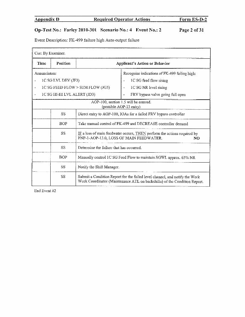
Appendix D Required Operator Actions Form ES-D-2
Op-Test No.: Farley 2010-3 01 Scenario No.: 4 Event No.: 2 Page 2 of 31
Event Description: FK-499 failure high Auto output failure
Cue: By Examiner.
Time Position Applicant’s Action or Behavior
Annunciators: Recognize indications of FK-499 failing high:
- 1C SG LVL DEV (JF3) - 1C SG feed flow rising
- 1C SG FEED FLOW> STM FLOW (JG3) - 1C SO NR level rising
- 1C SO HI-HI LVL ALERT (JD3) - FRV bypass valve going full open
AOP-100, section 1.5 will be entered.(possible_AOP- 13_entry)
SS Direct entry to AOP-100, IOAs for a failed FRV bypass controller
BOP Take manual control of FK-499 and DECREASE controller demand
SS IF a loss of main feedwater occurs, THEN perform the actions required byFNP-1-AOP-13.O, LOSS OF MAIN FEEDWATER. NO
SS Determine the failure that has occmTed.
BOP Manually control 1C SO Feed Flow to maintain SGWL approx. 65% NR
SS Notify the Shift Manager.
SS Submit a Condition Report for the failed level channel, and notify the WorkWeek Coordinator (Maintenance ATL on backshifts) of the Condition Report.
End Event #2
Appendix D Required Operator Actions Form ES-D-2
Op-Test No.: Farley 2010-301 Scenario No.: 4 Event No.: 2 Page 2 of 31
Event Description: FK-499 failure high Auto output failure
~~ • 'J Examiner.
Time Position Applicant's Action or Behavior
Annunciators: Recognize indications ofFK-499 failing high:
- 1 C SG L VL DEV (JF3) - 1 C SG feed flow rising
- IC SG FEED FLOW> STM FLOW (JG3) - 1 C SG NR level rising
- IC SG HI-HI LVLALERT (JD3) - FRV bypass valve going full open
AOP-lOO, section 1.5 will be entered. (possible AOP-13 entry)
SS Direct entry to AOP-lOO, IOAs for a failed FRV bypass controller
BOP Take manual control ofFK-499 and DECREASE controller demand
SS IF a loss of main feedwater occurs, THEN perfo1TI1 the actions required by FNP-I-AOP-13.0, LOSS OF MAIN FEEDWATER. NO
SS Determine the failure that has occurred.
BOP Manually controlIC SG Feed Flow to maintain SGWL approx. 65% NR
SS Notify the Shift Manager.
SS Submit a Condition Report for the failed level channel, and notify the Work Week Coordinator (Maintenance ATL on backshifts) of the Condition Report.
End Event #2

Appendix D Required Operator Actions Form ES-D-2
Op-Test No.: Farley 2010-301 Scenario No.: 4 Event No.: 3 Page 3 of 31
Event Description: LT-459 fails HIGH, controlling Pressurizer level channel.
Cue: By Examiner.
Time Position Applicant’s Action or Behavior
Annunciators: Indications for LT-459 failure:
- CHG HDR FLOW HI-LO (EA2) - LI-459 increases to 100%
- PRZR LVL HI RX TRIP ALERT (HAl) - Charging flow FI-122A Decreases
- PRZR LVL DEV HI B/U HTRS ON (HA2)
AOP-100, section 1.2 will be entered.
SS Directs BOP to address ARPs:
• EA2, CHG HDR FLOW HI-LO
SS Enters AOP-l00, Section 1.2. Directs RO & BOP actions per rows below:
RO Checks pressurizer level trending to or on program: NO
. Takes manual control of FK-122 and increases demand
• Adjusts Seal injection flows HIK-186: 6-13 gpm
• Reports that LT-459 is failed high
• Selects CHAN Ill/Il on LS-459Z to defeat input of LT-459 topressurizer level control
• Selects unaffected channel, either CHAN II or CHAN III on LS/459Y
BOP Verify CHG FLOW FK 122 is in MAN establish the required chargingflow
. Take Manual control of FK-122 and raise the demand
SS Refer to Tech Specs 3.3.1 & 3.3.3 for any LCO requirements.
3.3.1 table 3.3.1-1 #9 above P-7 mandatory LCO condition M
Place one channel in trip in 72 hours or reduce power to <P-7 in 78 hours
3.3.3 Table 3.3.3-1 #7 Admin LCO due to required channels is 2
SS Notify the Shift Manager and get concurrence to place controls in auto.
S [CA] WHEN plant conditions permit,THEN restore components to automatic control
BOP Restore charging flow control to automatic per SOP-2.1, FNP-1-SOP-2.l,CVCS PLANT STARTUP AND OPERATION,
. WHEN actual PRZR level is approximately equal to programmedlevel, THEN Place CHG FLOW FK 122 in AUTO and verify FK-122adjusts to maintain Pzr level.
Appendix D Required Operator Actions Form ES-D-2
Op-Test No.: Farley 2010-301 Scenario No.: 4 Event No.: 3 Page 3 of 31
Event Description: LT-459 fails HIGH, controlling Pressurizer level channel.
Cue: By Examiner.
Time Position Applicant's Action or Behavior
Annunciators: Indications for LT-459 failure:
- CHG HDR FLOW HI-LO (EA2) - LI-459 increases to 100%
- PRZR LVL HI RX TRIP ALERT (HAl) - Charging flow FI-l22A Decreases
- PRZR L VL DEV HI BIU HTRS ON (HA2)
AOP-lOO, section 1.2 will be entered.
SS Directs BOP to address ARPs:
• EA2, CHG HDR FLOW HI-LO
SS Enters AOP-lOO, Section 1.2. Directs RO & BOP actions per rows below:
RO Checks pressurizer level trending to or on program: NO
• Takes manual control ofFK-122 and increases demand
• Adjusts Seal injection flows HIK-186: 6-13 gpm
• Reports that LT-459 is failed high
• Selects CHAN III/II on LS-459Z to defeat input ofLT-459 to pressurizer level control
• Selects unaffected channel, either CHAN II or CHAN III on LS/459Y
BOP Verify CHG FLOW FK 122 is in MAN AND establish the required charging flow
• Take Manual control of FK-122 and raise the demand
SS Refer to Tech Specs 3.3.1 & 3.3.3 for any LCO requirements.
3.3.1 table 3.3.1-1 # 9 above P-7 mandatory LCO condition M
Place one channel in trip in 72 hours or reduce power to <P-7 in 78 hours
3.3.3 Table 3.3.3-1 #7 Admin LCO due to required channels is 2
SS Notify the Shift Manager and get concurrence to place controls in auto.
SS [CA] WHEN plant conditions permit,
THEN restore components to automatic control
BOP Restore charging flow control to automatic per SOP-2.1, FNP-1-S0P-2.1, CVCS PLANT STARTUP AND OPERATION,
• WHEN actual PRZR level is approximately equal to programmed level, THEN Place CHG FLOW FK 122 in AUTO and verify FK-122 adjusts to maintain Pzr level.

Appendix D Required Operator Actions Form ES-D-2
Op-Test No.: Farley 2010-301 Scenario No.: 4 Event No.: 3
Event Description: LT-459 fails HIGH, controlling Pressurizer level channel.
Page 4 of 31
END - Event 3
Submit a Condition Report for the failed level channel, and notify theWork Week Coordinator (Maintenance ATL on backshifts) of theCondition Report.
Appendix D Required Operator Actions Form ES-D-2
Op-Test No.: Farley 2010-301 Scenario No.: 4 Event No.: 3 Page 4 of 31
Event Description: LT-459 fails HIGH, controlling Pressurizer level channel.
SS Submit a Condition Report for the failed level channel, and notify the Work Week Coordinator (Maintenance ATL on backshifts) of the Condition Report.
END -Event 3
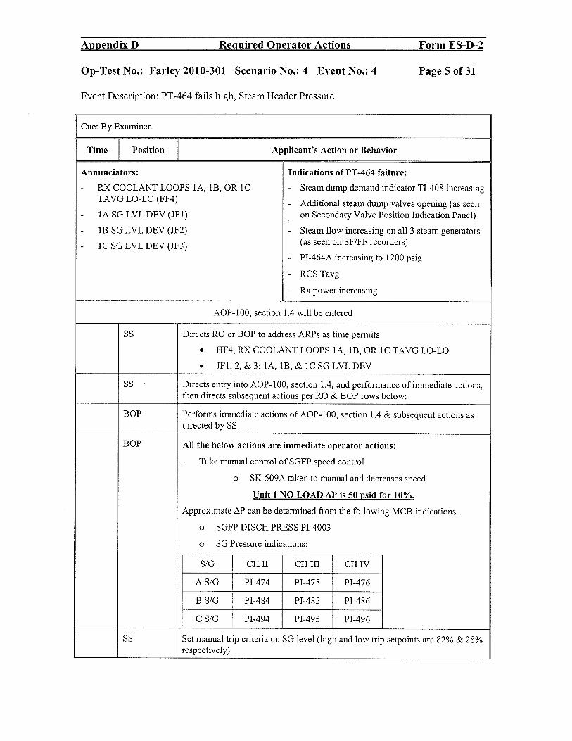
Appendix D Required Operator Actions Form ES-D-2
Op-Test No.: Farley 2010-301 Scenario No.: 4 Event No.: 4 Page 5 of 31
Event Description: PT-464 fails high, Steam Header Pressure.
Cue: By Examiner.
Time Position Applicant’s Action or Behavior
Annunciators: Indications of PT-464 failure:
- RX COOLANT LOOPS 1A, 1B, OR 1C - Steam dump demand indicator TI-408 increasingTAVG LO-LO (FF4)
- Additional steam dump valves opening (as seen- 1A SG LVL DEV (JF1) on Secondary Valve Position Indication Panel)
- lB SG LVL DEV (JF2) - Steam flow increasing on all 3 steam generators
- 1C SG LVL DEV (JF3) (as seen on SF/FF recorders)
- PI-464A increasing to 1200 psig
- RCS Tavg
- Rx power increasing
AOP-l00, section 1.4 will be entered
SS Directs RO or BOP to address ARPs as time permits
. HF4, RX COOLANT LOOPS 1A, 1B, OR IC TAVG LO-LO
. JF1,2,&3: 1A, 1B,& 1CSGLVLDEV
SS Directs entry into AOP-100, section 1.4, and performance of immediate actions,then directs subsequent actions per RO & BOP rows below:
BOP Performs immediate actions of AOP-100, section 1.4 & subsequent actions asdirected by SS
BOP All the below actions are immediate operator actions:
- Take manual control of SGFP speed control
o SK-509A taken to manual and decreases speed
Unit 1 NO LOAD AP is 50 psid for 10%.
Approximate AP can be determined from the following MCB indications.
o SGFP DISCH PRESS P1-4003
o SG Pressure indications:
S/G CHIT CH ITT CH IV
A 5/0 P1-474 P1-475 P1-476
B S/C P1-484 P1-485 P1-486
C S/C P1-494 P1-495 P1-496
SS Set manual trip criteria on SC level (high and low trip setpoints are 82% & 28%respectively)
Appendix D Required Operator Actions Form ES-D-2
Op-Test No.: Farley 2010-301 Scenario No.: 4 Event No.: 4 Page 5 of 31
Event Description: PT -464 fails high, Steam Header Pressure.
Cue: By Examiner.
Time Position I Applicant's Action or Behavior
Annunciators: Indications of PT -464 failure:
- RX COOLANT LOOPS lA, IB, OR IC - Steam dump demand indicator TI-408 increasing TAVG LO-LO (FF4) - Additional steam dump valves opening (as seen
- lA SG LVL DEV (lFl) on Secondary Valve Position Indication Panel)
- lB SG L VL DEV (JF2) - Steam flow increasing on all 3 steam generators
- lC SG LVL DEV (JF3) (as seen on SF IFF recorders)
- PI-464A increasing to 1200 psig
- RCS Tavg
- Rx power increasing
AOP-lOO, section 1.4 will be entered
SS Directs RO or BOP to address ARPs as time permits
• HF4, RX COOLANT LOOPS lA, lB, OR lC TAVG LO-LO
• lFl, 2, & 3: lA, lB, & lC SG LVL DEV
SS Directs entry into AOP-lOO, section 1.4, and performance of immediate actions, then directs subsequent actions per RO & BOP rows below:
BOP Performs immediate actions of AOP-lOO, section 1.4 & subsequent actions as directed by SS
BOP All the below actions are immediate operator actions:
- Take manual control of SGFP speed control
0 SK-509A taken to manual and decreases speed
Unit 1 NO LOAD AP is 50 [!sid for 10%.
Approximate 6P can be determined from the following MCB indications.
0 SGFP DISCH PRESS PI-4003
0 SG Pressure indications:
S/G CHII CHIlI CHIV
AS/G PI-474 PI-475 PI-476
B S/G PI-484 PI-485 PI-486
C S/G PI-494 PI-495 PI-496
SS Set manual trip criteria on SG level (high and low trip setpoints are 82% & 28% respectively)

Appendix B Required Operator Actions Form ES-D-2
Op-Test No.: Farley 2010-301 Scenario No.: 4 Event No.: 4 Page 6 of 31
Event Description: PT-464 fails high, Steam Header Pressure.
SS Directs BOP operator to manually operate steam dumps to prevent opening ofSG atmospheric relief valves as RCS temperature recovers
BOP Take manual control of the steam dumps and adjust to maintain Tavg at approx550°F.
o STM HDR PRESS PK-464
RO Monitors and determines RCS Tavg below 543 °F. On 2/3 loops and informs SS
SS Notifies Shift Manager
Submits a CR & Notifies the Work Week Coordinator
SS Enters LCO 3.4.2, RCS Minimum Temperature for Criticality: Be in Mode 3 in30 minutes: IF Tavg 541°F
End event 4
Appendix D Required Operator Actions Form ES-D-2
Op-Test No.: Farley 2010-301 Scenario No.: 4 Event No.: 4 Page 6 of31
Event Description: PT -464 fails high, Steam Header Pressure.
SS Directs BOP operator to manually operate steam dumps to prevent opening of SG atmospheric relief valves as RCS temperature recovers
BOP Take manual control of the steam dumps and adjust to maintain Tavg at approx 550°F.
0 STM HDR PRESS PK-464
RO Monitors and determines RCS Tavg below 543 of. On 2/3 loops and informs SS
SS Notifies Shift Manager
Submits a CR & Notifies the Work Week Coordinator
SS Enters LCO 3.4.2, RCS Minimum Temperature for Criticality: Be in Mode 3 in 30 minutes: IF Tavg < 541°F
End event 4

Appendix D Required Operator Actions Form ES-D-2
Op-Test No.: Farley 2010-301 Scenario No.: 4 Event No.: 5 Page 7 of 31
Event Description: An RCS 75 GPM leak on 1A RCS loop develops
Cue: By Examiner.
Time Position Applicant’s Action or Behavior
Annunciators: Indications for RCS leak:
- CHG HDR FLOW HI-LO (EA2) - CTMT radiation monitors R-2, R-7, and Ri 1
- RMS HI RAD (FH1) increasing
- BOP PANELS ALARM (BE5) - PRZR level decreasing
- CTMT SUMP LVL HI-HI OR TRBL (PG3)- PR pressure decreasing
- Charging flow increasing (on FI-122A)
- CTMT sump level increasing (on L13282A and B)
AOP-i .0 entry required
Unit 2 will experience a Safety Injection at step 1 of AOP-1.0.
This will be announced after the alarms come in.
SS Directs performance of ARPs
• EA2, CHG HDR FLOW HI-LO
. FH1, RMS HI RAD (R-2, 7, & 12: CTMT radiation alarms in)
RO Reports pressurizer level is dropping with charging maximum
. May take manual control of charging FK- 122 and raise demand to100%
. May request to take one or both letdown orifices off service
. May diagnose and announce RCS leak
BOP Performs actions of ARP EA2, CHG HDR FLOW HI-LO:
• Determines RCS leak indicated, directs to AOP-1.0, RCS LEAKAGE
Performs actions of ARP FH1, RMS HI RAD, for alarms R-2, R-7, & R-12
. Determines RCS leak indicated, directs to AOP-i.0, RCS LEAKAGE
SS Directs entry into AOP-l and directs actions per RO & BOP rows below:
RO • Maintain PRZR level stable at or near programmed level
o Adjusts FK-122 to raise charging flow
o Reduces letdown flow by opening one or both orifice isolationvalves HV8 149 A & C
o Establishes charging and letdown flow rates to stabilizepressurizer level
• Ensures Reactor makeup is in AUTOMATIC to maintain VCT level>20%
Appendix D Required Operator Actions Form ES-D-2
Op-Test No.: Farley 2010-301 Scenario No.: 4 Event No.: 5 Page 7of31
Event Description: An RCS 75 GPM leak on lA RCS loop develops
Cue: By Examiner.
TIllie Position Applicant's Action or Behavior
Annunciators: Indications for ReS leak:
- CRG RDR FLOW HI-LO (EA2) - CTMT radiation monitors R-2, R-7, and R11
- RMS HI RAD (FR1) increasing
- BOP PANELS ALARM (BES) - PRZR level decreasing
- CTMT SUMP L VL HI-HI OR TRBL (PG3) - PRZR pressure decreasing
- Charging flow increasing (on FI-122A)
- CTMT sump level increasing (on LI3282A and B)
AOP-l.O entry required
Unit 2 will experience a Safety Injection at step 1 of AOP-l.0.
This will be announced after the alarms come in.
SS Directs performance of ARPs
• EA2, CRG RDR FLOW HI-LO
• FRl, RMS HI RAD (R-2, 7, & 12: CTMT radiation alarms in)
RO Reports pressurizer level is dropping with charging maximum
• May take manual control of charging FK-l22 and raise demand to 100%
• May request to take one or both letdown orifices off service
• May diagnose and announce RCS leak
BOP Perf0l11lS actions of ARP EA2, CRG RDR FLOW HI-LO:
• Determines RCS leak indicated, directs to AOP-l.O, RCS LEAKAGE
Performs actions of ARP FRl, RMS HI RAD, for alarms R-2, R-7, & R-12
• Determines RCS leak indicated, directs to AOP-l.O, RCS LEAKAGE
SS Directs entry into AOP-1 and directs actions per RO & BOP rows below:
RO • Maintain PRZR level stable at or near programmed level
0 Adjusts FK-122 to raise charging flow
0 Reduces letdown flow by opening one or both orifice isolation valves RV8149 A & C
0 Establishes charging and letdown flow rates to stabilize pressurizer level
• Ensures Reactor makeup is in AUTOMATIC to maintain VCT level> 20%

Appendix D Required Operator Actions Form ES-D-2
Op-Test No.: Farley 2010-301 Scenario No.: 4 Event No.: 5 Page 8 of 31
Event Description: An RCS 75 GPM leak on 1A RCS ioop develops
RO Determine leak rate based on flow balance
flow)
+ (seal injection flow)
- (letdown flow)
- (#1 seal leakoff flow)
= (RCS leak rate)
BOP • Reports R-2, R-7, & R-12 are in alarm. R-1 1 is upscale or in alarm
SS WHEN RCS leak rate determined, THEN evaluate required actions usingTeclmical Specifications.
• Enters LCO 3.4.13 for unidentified RCS Operational LEAKAGECondition A (don’t know if it is pressure boundary leakage or not untilCTMT entry made to inspect):
o fix leak in 4 hours or shutdown in 6 hours
SS WHEN RCS leak rate determined, THEN evaluate event classification andnotification requirements using FNP-0-EIP-8, NON-EMERGENCYNOTIFICATIONS and FNP-0-EIP-9, EMERGENCY CLASSIFICATIONAND ACTIONS.
• Informs Shift Manager of
o Leak rate for classification and notification per EIP-8 & EIP9.0
o need for CTMT entry to look for leak source
o T.S. requires fix leak in 4 hours or shutdown in 6 hours
SS Directs Unit 2 UO or extra plant operator or SSS to align 1A & lB post LOCAcontainment hydrogen analyzers for service using Attachment 1
RO Frequently monitor CVCS flow balance as the actions of steps 7.2 through 7.12are taken.
BOP Check containment radiation — NORMAL NO
SS • Consult Shift Manager to evaluate requirement for containment entry
• Evaluate placing CTMT sump pump handswitches in PULL-TOLOCK to prevent overfilling the WHT.
BOP Verify containment ventilation isolation
• Stop MINI PURGE SUPP/EXH FAN.
• Verify containment mini purge dampers - CLOSED.
• CTMT PURGE DMPRS
Appendix D Required Operator Actions Form ES-D-2
Op-Test No.: Farley 2010-301 Scenario No.: 4 Event No.: 5 Page 8 of 31
Event Description: An RCS 75 GPM leak on lA RCS loop develops
RO Determine leak rate based on flow balance
(charging flow)
+ (seal injection flow)
- (letdown flow)
- (#1 sea11eakoff flow)
= (RCS leak rate)
BOP • Reports R-2, R-7, & R-12 are in alarm. R-11 is upscale or in alarm
SS WHEN RCS leak rate determined, THEN evaluate required actions using Technical Specifications.
• Enters LCO 3.4.13 for unidentified RCS Operational LEAKAGE Condition A (don't know if it is pressure boundary leakage or not until CTMT entry made to inspect):
0 fix leak in 4 hours or shutdown in 6 hours
SS WHEN RCS leak rate determined, THEN evaluate event classification and notification requirements using FNP-0-EIP-8, NON-EMERGENCY NOTIFICATIONS andFNP-0-EIP-9, EMERGENCY CLASSIFICATION AND ACTIONS.
• Informs Shift Manager of
0 Leak rate for classification and notification per EIP-8 & EIP-9.0
0 need for CTMT entry to look for leak source
0 T.S. requires fix leak in 4 hours or shutdown in 6 hours
SS Directs Unit 2 UO or extra plant operator or SSS to align 1A & 1B post LOCA containment hydrogen analyzers for service using Attachment 1
RO Frequently monitor CVCS flow balance as the actions of steps 7.2 through 7.12 are taken.
BOP Check containment radiation - NORMAL NO
SS • Consult Shift Manager to evaluate requirement for containment entry
• Evaluate placing CTMT sump pump hands witches in PULL-TO-LOCK to prevent overfilling the WHT.
BOP Verify containment ventilation isolation
• Stop MINI PURGE SUPP/EXH FAN.
• Verify containment mini purge dampers - CLOSED.
• CTMT PURGE DMPRS

Appendix D Required Operator Actions Form ES-D-2
Op-Test No.: Farley 2010-301 Scenario No.: 4 Event No.: 5 Page 9 of 31
Event Description: An RCS 75 GPM leak on IA RCS ioop develops
MfNI-2866C & 2867C
. CTMT PURGE DMPRSMINI-2866D & 2867D
BOP Check auxiliary building radiation - NORMAL. YES
BOP Check no SG tube leakage NO SG leakage
BOP • Check Secondary radiation NORMAL YES
• Checks CCW radiation monitors (R- 1 7A!B) YES
• Checks Aux Bldg sumps — on BOP
• Checks CTMT sump - on BOP uses STP-70.O CONTAINMENT SUMPSURVEILLANCE
Go to next event
Event Termination point:
LCO 3.4.13 Cond. A identified
SM informed of plant status
END - Event 5
Appendix D Required Operator Actions Form ES-D-2
Op-Test No.: Farley 2010-301 Scenario No.: 4 Event No.: 5 Page 9 of31
Event Description: An RCS 75 GPM leak on lA RCS loop develops
MINI-2866C & 2867C
• CTMT PURGE DMPRS MINI-2866D & 2867D
BOP Check auxiliary building radiation - NORMAL. YES
BOP Check no SG tube leakage NO SG leakage
BOP • Check Secondary radiation NORMAL YES
• Checks CCW radiation monitors (R-17A1B) YES
• Checks Aux Bldg sumps - on BOP
• Checks CTMT sump - on BOP uses STP-70.0 CONTAINMENT SUMP SURVEILLANCE
Go to next event
Event Termination point:
LCO 3.4.13 Condo A identified
SM informed of plant status
END -Event 5

Appendix D Required Operator Actions Form ES-D-2
Op-Test No.: Farley 2010-301 Scenario No.: 4 Event No.: 6 Page 10 of 31
Event Description: 1A RCP spray valve fails OPEN.
Cue: By Examiner.
Time Position Applicant’s Action or Behavior
Annunciators: Indications for failed spray valve:
PRZR PRESS HI-LO (HC1) - RCS pressure decreasing
PRZR HI-LO PRESS ALERT (HC2) - PK-444B, 1A spray valve controller, output
PRZR PRESS REL VLV 445A OR B/U HTRS meter increases to 100
ON (HD 1) - 1A spray valve valve position lights are dark
AOP-l00, section 1.1 entry required
SS Directs AOP-100 section 1.1 immediate actions and subsequent actions per RO& BOP rows below:
RO Take manual control to raise RCS pressure: (These are lOAs)
• PORVs PCV445 & 444B
• Sprays PK-444C & D
. Heaters 1A, 1B, 1C, 1D, 1E
. PK-444A PRZR PRESS REFERENCE controller
• Reports that the spray valve is stuck open and a reactor trip is requiredprior to 2100 psig
• Trips reactor and completes inmediate actions of EEP-0.0
BOP (These are lOAs)
Verifies Reactor is tripped and:
. THEN (if directed by SS) secures 1A & lB RCPs
SS Directs Manually tripping the reactor and directs the BOP to secure 1A and lBRCPs secured AFTER the reactor is tripped. Directs performance of immediateoperator actions, then Updates crew on EEP-0 entry.
RO / BOP Immediate Operator actions of EEP-0
Check reactor trip.Check all reactor trip breakers and reactor tripbypass breakers - OPEN. YES
Check reactor trip.
Check nuclear power - FALLING.Check rod bottom lights - LIT. YESCheck turbine - TRIPPED. YESTSLB2 14-1 thru 4 lit
Check power to 4160 V ESF busses.
Appendix D Required Operator Actions Form ES-D-2
Op-Test No.: Farley 2010-301 Scenario No.: 4 Event No.: 6 Page 10 of 31
Event Description: lA Rep spray valve fails OPEN.
Cue: By Examiner.
.llUlto Position Applicant's Action or Behavior
Annunciators: Indications for failed spray valve:
- PRZR PRESS HI-LO (HCI) - RCS pressure decreasing
- PRZR HI-LO PRESS ALERT (HC2) - PK-444B, IA spray valve controller, output
PRZR PRESS REL VL V 445A OR BfU HTRS meter increases to 100 -ON (HDl) - IA spray valve valve position lights are dark
AOP-IOO, section 1.1 entry required
SS Directs AOP-1 00 section 1.1 immediate actions and subsequent actions per RO & BOP rows below:
RO Take manual control to raise RCS pressure: (These are IOAs)
• PORVs PCV445 & 444B
• Sprays PK-444C & D
• Heaters lA, lB, 1C, lD, IE
• PK-444A PRZR PRESS REFERENCE controller
• Reports that the spray valve is stuck open and a reactor trip is required prior to 2100 psig
• Trips reactor and completes inmlediate actions ofEEP-O.O
BOP (These are IOAs)
Verifies Reactor is tripped and:
• THEN (if directed by SS) secures 1A & 1B RCPs
SS Directs Manually tripping the reactor and directs the BOP to secure 1A and lB RCPs secured AFTER the reactor is tripped. Directs perfonnance of il1ill1ediate operator actions, then Updates crew on EEP-O entry.
RO/BOP Inmlediate Operator actions of EEP-O
Check reactor trip. Check all reactor trip breakers and reactor trip bypass breakers - OPEN. YES
Check reactor trip.
Check nuclear power - FALLING. Check rod bottom lights - LIT. YES Check turbine - TRIPPED. YES TSLB2 14-1 thru 4 lit
Check power to 4160 V ESF busses.

Appendix D Required Operator Actions Form ES-D-2
Op-Test No.: Farley 2010-301 Scenario No.: 4 Event No.: 6 Page 11 of 31
Event Description: 1A RCP spray valve fails OPEN.
4160 V ESF busses - AT LEAST ONE ENERGIZED YES
A Train (F & K) power available lights litORB Train (G & L) power available lights lit
Verify operating diesel generators are being supplied from at YESleast one SW pump.
RO / BOP • Check any SI actuated indication
- BYP & PERMISSIVE SAFETY INJECTION NO[] ACTUATED status light lit[] MLB-l 1-1 lit
[] MLB-l 11-1 lit
IF TSLB bistables meet coincidence for SI, THEN SI is required.PRZRPRESSLO 1850 2/3 TSLB2 17-, 17-2, 17-3• IF any parameter shown in the Table below has been lit reached or
exceeded, THEN SI is required.• Transition to ESP-0.l
SS Will direct entry into ESP-0. 1 and UPDATE the crew.
RO Check RCS temperature stable at or approaching 547°F.
On TI 412D, 422D and 432D
RNO should not have to be performed.
BOP WHEN RCS average temperature less than 554°F, THEN verify feedwaterstatus.
o Verify Main FW FCVs and Bypass valves CLOSED
o Defeat the Auto start on SGFP trip
o Verify BOTH SGFPs tripped
RO Verify all RTBs OPEN
Check emergency boration NOT required
o Check All rods fully inserted
o Check RCS Tavg >525°F.
o Announce “Unit 1 reactor trip”.
BOP Check AFW status.
o Check total AFW flow - GREATER THAN 395 gpm.
o Check any SG narrow range TDAFWP level - GREATER THAN 31%.
End of event 6
Appendix D Required Operator Actions Form ES-D-2
Op-Test No.: Farley 2010-301 Scenario No.: 4 Event No.: 6 Page 11 of 31
Event Description: lA Rep spray valve fails OPEN.
4160 V ESF busses - AT LEAST ONE ENERGIZED YES
A Train (F & K) power available lights lit OR B Train (G & L) power available lights lit
Verify operating diesel generators are being supplied from at YES least one SW pump.
RO/BOP • Check any SI actuated indication
- BYP & PERMISSIVE SAFETY INJECTION NO [] ACTUATED status light lit [] MLB-l 1-1 lit [] MLB-l 11-1 lit
* IF TSLB bistables meet coincidence for SI, THEN SI is required. PRZRPRESS LO 18502/3 TSLB2 17-, 17-2, 17-3
• IF any parameter shown in the Table below has been lit reached or exceeded, THEN SI is required.
• Transition to ESP-O.l
SS Will direct entry into ESP-O.l and UPDATE the crew.
RO Check RCS temperature stable at or approaching 547°F.
On TI 4l2D, 422D and 432D
RNO should not have to be performed.
BOP WHEN RCS average temperature less than 554°F, THEN verify feedwater status.
0 Verify Main FW FCVs and Bypass valves CLOSED
0 Defeat the Auto start on SGFP trip
0 Verify BOTH SGFPs tripped
RO Verify all RTBs OPEN
Check emergency boration NOT required
0 Check All rods fully inserted
0 Check RCS Tavg >525°F.
0 Announce "Unit 1 reactor trip".
BOP Check AFW status.
0 Check total AFW flow - GREATER THAN 395 gpm.
0 Check any SG narrow range TDAFWP level - GREATER THAN 31 %.
End of event 6

Appendix B Required Operator Actions Form ES-D-2
Op-Test No.: Farley 201 0-301 Scenario No.: 4 Event No.: 7 Page 12 of 31
Event Description: Loss of ALL AC power while in ESP-O.1 / TDAFWP does not auto start.
Time Position Applicant’s Action or BehaviorAnnunciators: Recognize indications of LOSS OF ALL AC
numerous - All lights in CR go out, then re-energize whenUnit 2 DGs tie on.
- All Unit 1 4160V emergency busses are deenergized
lB DG does not start when the LOSP occurs.
SS Recognize Loss of all AC and direct IOAs of ECP-O:
RO/BOP Immediate Operator actions of ECP-OCheck reactor tripped. No power1.1 Check reactor trip and reactor trip bypass breakers - OPEN.1.1.1 Manually trip reactor.[] Reactor trip breaker A{] Reactor trip breaker B[]Reactor trip bypass breaker A[j Reactor trip bypass breaker B
IF any reactor trip breaker NOT open or any reactor trip bypass breaker NOTopen, THEN locally open affected breaker. (121 ft, AUX BLDG rod controlroom)
Check nuclear power - FALLING. YESPR 1(2,3,4) PERCENT FULL POWER[1 NI 41B[]NI 42B
[J NI 43B[]NI 44B
IR1(2) CURRENT[]NI 35B[1 NI 36B
Check turbine tripped. YES[]TSLB2 14-1 lit[]TSLB2 14-2 lit[]TSLB2 14-3 lit[j TSLB2 14-4 lit
ROVerify RCS isolated.
o WHEN RCS pressure less than 2335 psig, THEN verify both PRZRPORVs closed.
o Verify normal letdown isolated. NOAll orifice isolation valves closed or letdown isolation valves closed
o Verify excess letdown line - ISOLATED. YESVerify Closed HV 8153 and 8154
Appendix D Required Operator Actions Form ES-D-2
Op-Test No.: Farley 2010-301 Scenario No.: 4 Event No.: 7 Page 12 of 31
Event Description: Loss of ALL AC power while in ESP-O.l / TDAFWP does not auto start.
Time Position I Annunciators: - numerous
Applicant's Action or Behavior Recognize indications of LOSS OF ALL AC - All lights in CR go out, then re-energize when
Unit 2 DGs tie on. - All Unit 1 4160V emergency busses are de
energized
1B DG does not start when the LOSP occurs.
SS Recognize Loss of all AC and direct IOAs of ECP-O:
RO/BOP
RO
Immediate Operator actions of ECP-O Check reactor tripped. No power 1.1 Check reactor trip and reactor trip bypass breakers - OPEN. 1.1.1 Manually trip reactor. [] Reactor trip breaker A [] Reactor trip breaker B [] Reactor trip bypass breaker A [] Reactor trip bypass breaker B
IF any reactor trip breaker NOT open or any reactor trip bypass breaker NOT open, THEN locally open affected breaker. (121 ft, AUX BLDG rod control room)
Check nuclear power - FALLING. PR1(2,3,4) PERCENT FULL POWER [] NI 41B [] NI 42B [] NI 43B [] NI44B
IRl(2) CURRENT [] NI 35B [] NI 36B
Check turbine tripped. [] TSLB2 14-1 lit [] TSLB2 14-2 lit [] TSLB2 14-3 lit [] TSLB2 14-4 lit
Verify ReS isolated.
YES
YES
o WHEN RCS pressure less than 2335 psig, THEN verify both PRZR PORVs closed.
o Verify normal letdown isolated. NO All orifice isolation valves closed or letdown isolation valves closed
o Verify excess letdown line - ISOLATED. YES Verify Closed HV 8153 and 8154

Appendix D Required Operator Actions Form ES-D-2
Op-Test No.: Fancy 2010-301 Scenario No.: 4 Event No.: 7 Page 13 of 31
Event Description: Loss of ALL AC power while in ESP-O.1 / TDAFWP does not auto start.
o Verify all reactor vessel head vent valves - CLOSED.RX VESSEL HEAD VENT OUTER ISO[]Q1B13SV2213A[]Q1B13SV2213B
RX VESSEL HEAD VENT INNER ISO[]Q1B13SV2214A
[j Q1B13SV2214B
BOP/ROCritical task
(CT)Verify total AFW flow GREATER THAN 395 gpm.AFW TOTAL FLOW[] Fl 3229
BOP [CA] Restore power to any emergency bus.Verify supply breakers for major loads on emergency 4160 V busses -
OPEN.
[]BKR DFO1 (1A S/U XFMR TO iF 4160 V BUS)
[]BKR DF15 (lB S/U XFMR TO iF 4160 V BUS)
[]BKR DF-13-1 (iF 4160 V BUS TIE TO 1114160 V BUS)
[1 BKR DGO1 (1A S/U XFMR TO 1G 4160 V BUS)
[1 BKR DG15 (lB S/U XFMR TO 1G 4160 V BUS
(]1A BATT CHARGER BKR ED-04-i
[1 1C BATT CHARGER A TRN BKRED-09-1
[]1C BATT CHARGER B TRN BKR EE-06-1
[1 lB BATT CHARGER BKR EE-05-1
[1 1C CCW PUMP BKR DF-04-1
[]1B CCW PUMP BKR DF-05-i
[I1B CCW PUMP BKR DG-05-1
LI 1A CCW PUMP BKR DG-04-1
[1 1A SW PUMP BKR DK-03-1
[1 lB SW PUMP BKR DK-04-l
[]1C SW PUMP BKR DK-05-1
[1 1C SW PUMP BKR DL-05-1
Appendix D Required Operator Actions Form ES-D-2
Op-Test No.: Farley 2010-301 Scenario No.: 4 Event No.: 7 Page 13 of31
Event Description: Loss of ALL AC power while in ESP-O.l / TDAFWP does not auto start.
0 Verify all reactor vessel head vent valves - CLOSED. RX VESSEL HEAD VENT OUTER ISO [] QIB13SV2213A [] QIB13SV2213B
RX VESSEL HEAD VENT INNER ISO [] QIB13SV2214A [] QIB13SV2214B
BOP/RO Critical task
(CT) Verify total AFW flow GREATER THAN 395 gpm. AFW TOTAL FLOW [] FI 3229
BOP [CAl Restore power to any emergency bus. Verify supply breakers for major loads on emergency 4160 V busses-OPEN.
[] BKR DFOI (IA S/u XFMR TO IF 4160 V BUS)
[] BKR DF15 (lB S/u XFMR TO IF 4160 V BUS)
[] BKR DF-13-1 (IF 4160 V BUS TIE TO IH 4160 V BUS)
[] BKR DGOI (IA S/u XFMR TO IG 4160 V BUS)
[] BKR DG15 (lB S/u XFMR TO IG 4160 V BUS
[] lA BATT CHARGER BKR ED-04-1
[] 1 C BATT CHARGER A TRN BKRED-09-1
[] lC BATT CHARGER B TRN BKR EE-06-1
[] lB BATT CHARGER BKR EE-05-1
[] lC CCW PUMP BKR DF-04-1
[] lB CCW PUMP BKR DF-05-1
[] lB CCW PUMP BKR DG-05-1
[] lA CCW PUMP BKR DG-04-1
[] lA SW PUMP BKR DK-03-1
[] lB SW PUMP BKR DK-04-1
[] lC SW PUMP BKRDK-05-1
n lC SW PUMP BKR DL-05-1

Appendix D Required Operator Actions Form ES-D-2
Op-Test No.: Fancy 2010-301 Scenario No.: 4 Event No.: 7 Page 14 of 31
Event Description: Loss of ALL AC power while in ESP-O.l / TDAFWP does not auto start.
[liD SW PUMP BKR DL-03-i
[]1E SW PUMP BKR DL-04-1
[1 #4 RW PUMP BKR DJ-03-1
[1 #5 RW PUMP BKR DJ04-1
[1 #8 RW PUMP BKR DH-03-i
[1 #9 RW PUMP BKR DH-044
[1 #10 RW PUMP BKR DH-05-i
[1 lB CRDM CLG FAN BKR ED41-i
[I 1A CRDM CLG FAN BKR EE-13-i
[1 1A CS PUMP BKR DF-ii-i
[1 lB CS PUMP BKRDG-ii-l
[1 1A RHR PUMP BKR DF-09-i
[1 lB RUR PUMP BKR DG-09-i
[1 1A CHG PUMP BKR DF-06-1
[1 lB CHG PUMP A TRN BKR DF-07-i
[jiB CHG PUMP B TRN BKR DG-07-l
[1 1C CHG PUMP BKR DG-06-i
[1 1A MDAFWP BKR DF-i0-i
[1 lB MDAFWP BKR DG-i0-i
(CT) BOP Check i-2A, 1C or lB diesel generator running for Unit 1. NO
Critical task
Perform 2C DG SBO start:o MSS in MODE 1o USS in UNIT 1o When load shed has been competed then depress START PB
2C DG will start
o Verify Unit 1 2C DG output breaker DJO6 closes. YESo Verify breaker DG13 closed. (1G 4160 V bus
tie to 1J416OVBUS)
Appendix D Required Operator Actions Form ES-D-2
Op-Test No.: Farley 2010-301 Scenario No.: 4 Event No.: 7 Page 14 of 31
Event Description: Loss of ALL AC power while in ESP-O.1 / TDAFWP does not auto start.
[] ID SW PUMP BKR DL-03-1
[] IE SW PUMP BKR DL-04-1
[] #4 RW PUMP BKR DJ-03-1
[] #5 RW PUMP BKR DJ-04-1
[] #8 RW PUMP BKR DH-03-1
[] #9 RW PUMP BKR DH-04-1
[] #10 RW PUMP BKR DH-05-1
[] 1B CRDM CLG FAN BKR ED-ll-l
[] lA CRDM CLG FAN BKR EE-13-1
[] lA CS PUMP BKR DF-ll-l
[] 1B CS PUMP BKR DG-ll-l
[] lARHRPUMPBKRDF-09-1
[] 1B RHR PUMP BKR DG-09-1
[] lA CHG PUMP BKR DF-06-1
[] IB CHG PUMP A TRN BKR DF-07-1
[] IB CHG PUMP B TRN BKR DG-07-1
[] lC CHG PUMP BKR DG-06-1
(] lA MDAFWP BKR DF-I0-l
(] 1B MDAFWP BKR DG-I0-l
(CT) BOP Check 1-2A, lC or IB diesel generator running for Unit 1. NO
Critical task
Perform 2C DG SBO start: 0 MSSinMODE 1 0 USS in UNIT 1 0 When load shed has been competed then depress START PB
2C DG will start
0 Verify Unit 1 2C DG output breaker DJ06 closes. YES 0 Verify breaker DG 13 closed. (1 G 4160 V bus
tie to 1J 4160 V BUS)

Appendix D Required Operator Actions Form ES-D-2
Op-Test No.: Farley 2010-301 Scenario No.: 4 Event No.: 7 Page 15 of 31
Event Description: Loss of ALL AC power while in ESP-0.1 / TDAFWP does not auto start.
o Verify breaker DGO2 closed. (1G 4160 V bustie to lL4l6OVbus)
o IF 1G 4160V bus energized, THEN proceed to YESstep 5.7
BOPVerify adequate SW flow.
o Verify two SW PUMPS in energized train - RUNNING. NO[j A Train (1A, lB or 1C)
[] B Train (1D, 1E or 1C)o IF A train energized, THEN verify SW TO/FROM DG NO
BLDG - A HDR Q1P16V519/537 open.o IF B train energized, THEN verify SW TO/FROM DG YES
BLDG - B HDR Q1P16V518/536 open.
BOPCheck no running diesel generator lube oil temperature annunciator inalarm. (155 ft, DG BLDG local control panel) NO
SSIF iF OR 1G 4160 V bus energized THEN go to procedure and stepin effect and implement function restoration procedures as necessary.
Return procedure and step in effect, ESP-O.1
End of event 7
Appendix D Required Operator Actions Form ES-D-2
Op-Test No.: Farley 2010-301 Scenario No.: 4 Event No.: 7 Page 15 of 31
Event Description: Loss of ALL AC power while in ESP-O.1 I TDAFWP does not auto start.
a Verify breaker DG02 closed. (1 G 4160 V bus tie to 1L 4160 V bus)
a IF 1 G 4160V bus energized, THEN proceed to YES step 5.7
BOP Verify adequate SW flow.
a Verify two SW PUMPS in energized train - RUNNING. NO [] A Train (lA, IB or lC)
[] B Train (ID, IE or IC) a IF A train energized, THEN verify SW TO/FROM DG NO
BLDG - A HDR Q1P16V519/537 open. a IF B train energized, THEN verify SW TOIFROM DG YES
BLDG - B HDR QIP16V518/536 open.
BOP Check no running diesel generator lube oil temperature annunciator in alarm. (155 ft, DG BLDG local control panel) NO
SS IF IF OR 1G 4160 V bus energized THEN go to procedure and step in effect and implement function restoration procedures as necessary.
Return procedure and step in effect, ESP-O.I
End of event 7

Appendix D Required Operator Actions Form ES-D-2
Op-Test No.: Farley 2010-301 Scenario No.: 4 Event No.: 8/9/10/11 Page 16 of 31
Event Description: LB LOCA occurs after second return to ESP-O. 1 after LOSP.8803A and B fail to open! 8820B does not open & ctmt cooler does not start
SS Direct return to EEP-0 and complete lOAs.
RO / BOP Immediate Operator actions of EEP-O
Check reactor trip.Check all reactor trip breakers and reactor tripbypass breakers - OPEN. YES
Check reactor trip.
Check nuclear power - FALLING.Check rod bottom lights - LIT. YES
Check turbine - TRIPPED. YESTSLB2 14-1 thru 4 lit
Check power to 4160 V ESF busses.4160 V ESF busses - AT LEAST ONE ENERGIZED YES
A Train (F & K) power available lights litORB Train (G & L) power available lights lit
Verify operating diesel generators are being supplied from at YESleast one SW pump.
(CT) RO / BOP Critical task
• Check any SI actuated indication
- BYP & PERMISSIVE SAFETY INJECTION NO[] ACTUATED status light lit[] MLB-1 1-1 lit[]MLB-l 11-1 lit
IF TSLB bistables meet coincidence for SI, THEN SI is required.PRZRPRESSLO 1850 2/3 TSLB2 17-1, 17-2, 17-3. IF any parameter shown in the Table below has been lit reached or
exceeded, THEN SI is required.Actuate a SI by this point in the procedure
When SS Direct actions required if FRP-P.l is in at this time or when it does come in.required
This will be entry and then exit once the first few steps are read.
Appendix D Required Operator Actions Form ES-D-2
Op-Test No.: Farley 2010-301 Scenario No.: 4 Event No.: 8/9/10/11 Page 16 of 31
Event Description: LB LOCA occurs after second return to ESP-O.l after LOSP. 8803A and B fail to open/ 8820B does not open & ctmt cooler does not start
SS Direct return to EEP-O and complete IOAs.
RO/BOP Immediate Operator actions ofEEP-O
Check reactor trip. Check all reactor trip breakers and reactor trip bypass breakers - OPEN.
Check reactor trip.
Check nuclear power - FALLING. Check rod bottom lights - LIT.
Check turbine - TRIPPED. TSLB2 14-1 thru 4 lit
Check power to 4160 V ESF busses. 4160 V ESF busses - AT LEAST ONE ENERGIZED
A Train (F & K) power available lights lit OR B Train (G & L) power available lights lit
Verify operating diesel generators are being supplied from at least one SW pump.
(CT) RO/BOP Critical task
• Check any SI actuated indication
- BYP & PERMISSIVE SAFETY INJECTION [] ACTUATED status light lit [] MLB-l 1-1 lit [] MLB-l 11-1 lit
* IF TSLB bistables meet coincidence for SI, THEN SI is required. PRZRPRESS LO 1850213 TSLB2 17-1, 17-2, 17-3
• IF any parameter shown in the Table below has been lit reached or exceeded, THEN SI is required.
Actuate a SI by this I!oint in the I!rocedure
YES
YES
YES
YES
YES
NO
When SS Direct actions required ifFRP-P.l is in at this time or when it does come in. required
This will be entry and then exit once the first few steps are read.

Appendix D Required Operator Actions Form ES-D-2
Op-Test No.: Farley 2010-301 Scenario No.: 4 Event No.: 8/9/10/11 Page 17 of 31
Event Description: LB LOCA occurs after second return to ESP-O. 1 after LOSP.8803A and B fail to open! 8820B does not open & ctmt cooler does not start
Direct actions required by FRP-Z. 1 if actions to align the Ctmt spray system arenot taken in a timely manner.
These actions are:
1. Verify Phase A actuated
2. Verify Ctmt ventilation isolation
3. Check CS required YES
Critical task
4. Verify valve alignment
5. Stop all RCPs
6. Verify ctmt cooler alignment
7. Verfiy proper SW flow path
8. Verify MSIVs closed
9. Check if Feed flow to the SGs should be isolated
SSWhenrequired
(CT)
Opens 8820B
Start iD/iC ctmt cooler
No SG faulted
SS Directs continuing into EEP-O at step 5.
Directs the BOP to do Attachment 2.
BOP Verifies actuation signal automatic actions using ATTACHMENT 2,AUTOMATIC ACTIONS VERIFICATION.
See Tab at end of scenario Attachment 2 and 4 for actions
SS / RO [CA] Check containment pressure- HASREMAINED LESS THAN 27 psig NOCTMT PRESS[] PR 950
Verify PHASE B CTMT ISO - ACTUATED. YES
. Stop all RCPs
. Verify PHASE B CTMT ISO alignment
• Check All MLB-3 lights lit. NO
. IF any MLB-3 light NOT lit, THEN verify PHASE B CTMT ISO using
(CT) ATTACHMENT 5, PHASE B CONTANMENT ISOLATION.
Critical task
• Opens 8820B
SS / RO Announce “Unit 1 reactor trip and safety injection”.
SS / RO Check AFW status.Check secondary heat sink Available
Appendix D Required Operator Actions Form ES-D-2
Op-Test No.: Farley 2010-301 Scenario No.: 4 Event No.: 8/9/10/11 Page 17 of 31
Event Description: LB LOCA occurs after second return to ESP-O.l after LOSP. 8803A and B fail to open/ 8820B does not open & ctmt cooler does not start
When required
(CT)
(CT)
SS Direct actions required by FRP-Z.l if actions to align the Ctmt spray system are not taken in a timely manner.
These actions are:
1. Verify Phase A actuated
2. Verify Ctmt ventilation isolation
3. Check CS required YES
Critical task
4. Verify valve alignment Opens 8820B
5. Stop all RCPs
6. Verify ctmt cooler alignment Start IDIlC ctmt cooler
7. Verfiy proper SW flow path
8. Verify MSIVs closed
9. Check if Feed flow to the SGs should be isolated No SG faulted
SS Directs continuing into EEP-O at step 5.
Directs the BOP to do Attachment 2.
BOP Verifies actuation signal automatic actions using ATTACHMENT 2, AUTOMATIC ACTIONS VERIFICATION.
SS/RO
See Tab at end of scenario Attachment 2 and 4 for actions
[CAl Check containment pressure- HAS REMAINED LESS THAN 27 psig CTMTPRESS [] PR 950
Verify PHASE B CTMT ISO - ACTUATED.
• Stop all RCPs
• Verify PHASE B CTMT ISO alignment
• Check All MLB-3 lights lit.
NO
YES
NO
• IF any MLB-3 light NOT lit, THEN verify PHASE B CTMT ISO using ATTACHMENT 5, PHASE B CONTAINMENT ISOLATION.
Critical task
• Opens 8820B
SS/RO Announce "Unit 1 reactor trip and safety injection".
SS/RO Check AFW status. Check secondary heat sink Available

Appendix D Required Operator Actions Form ES-D-2
Op-Test No.: Farley 2010-301 Scenario No.: 4 Event No.: 8/9/10/11 Page 18 of 31
Event Description: LB LOCA occurs after second return to ESP-O. 1 after LOSP.8803A and B fail to open! 8820B does not open & ctmt cooler does not start
o Check total AFW flow> 395 gpm[]FI 3229A[]FI 3229B[]Fl 3229C
o Total Flow Fl 3229OR
o Check any SG NR level> 31% {48%}
o WHEN all SG narrow range levels less than 3 l%{48%},THEN maintain total AFW flow greater than 395 gpm.
o WHEN at least two SG narrow range levels greater than 28%AND TDAFWP NOT required, THEN stop TDAFWP.
[CA] WHEN SG narrow range level greater than 31%{48%},THEN maintain SG narrow range level 31%-65%{48%-65%}.
o Control MDAFWP flow.MDAFWP FCV 3227 RESET[]A TRN reset[] B TRN resetMDAFWP TO lA/lB/iC SG B TRN[]FCV 3227 in MOD
o Control TDAFWP flow.TDAFWP FCV 3228[1 RESET resetTDAFWP SPEED CONT[]SIC 3405 adjusted
SS/ROCheck RCS temperature.IF any RCP running, THEN check RCS average temperature - STABLE AT ORAPPROACHING 547°F.TAVG 1A(1B,1C) RCS LOOP[]TI 412D[]TI 422D[]T1432D
RNOIF RCS temperature less than 547°F and falling, THEN perform the following.Verify steam dumps closed.STM DUMP INTERLOCK[j A TRN in OFF RESET[1 B TRN in OFF RESET
Verify atmospheric reliefs closed on MCB Demand at 0 andminimum red light LIT
Control total AFW flow to minimize RCS cooldown,AFW FLOW TO 1A(1B,1C) SG
Appendix D Required Operator Actions Form ES-D-2
Op-Test No.: Farley 2010-301 Scenario No.: 4 Event No.: 8/9/10/11 Page 18 of 31
Event Description: LB LOCA occurs after second return to ESP-O.l after LOSP. 8803A and B fail to open/ 8820B does not open & ctmt cooler does not start
0 Check total AFW flow> 395 gpm [] FI 3229A [] FI 3229B [] FI 3229C
0 Total Flow FI 3229 OR
0 Check any SG NR level> 31 % {48%}
0 WHEN all SG narrow range levels less than 31 % {48%}, THEN maintain total AFW flow greater than 395 gpm.
0 WHEN at least two SG narrow range levels greater than 28% AND TDAFWP NOT required, THEN stop TDAFWP.
[CA] WHEN SG narrow range level greater than 3l%{48%}, THEN maintain SG narrow range level 31 %-65%{48%-65%}.
0 Control MDAFWP flow. MDAFWP FCV 3227 RESET [] A TRN reset [] B TRN reset MDAFWP TO lA/lB/l C SG B TRN [] FCV 3227 in MOD
0 Control TDAFWP flow. TDAFWP FCV 3228 [] RESET reset TDAFWP SPEED CONT [] SIC 3405 adjusted
SSIRO Check RCS temperature. IF any RCP mnning, THEN check RCS average temperature - STABLE AT OR APPROACHING 547°F. TAVG lA(lB,lC) RCS LOOP [] TI 4l2D [] TI 422D [] TI 432D
RNO IF RCS temperature less than 547°F and falling, THEN perform the following. Verify steam dumps closed. STM DUMP INTERLOCK [] A TRN in OFF RESET [] B TRN in OFF RESET
Verify atmospheric reliefs closed on MCB Demand at 0 and minimum red light LIT
Control total AFW flow to minimize RCS cooldown, AFW FLOW TO lA(lB,lC) SG

Appendix D Required Operator Actions Form ES-D-2
Op-Test No.: Farley 2010-301 Scenario No.: 4 Event No.: 8/9/10/11 Page 19 of 31
Event Description: LB LOCA occurs after second return to ESP-0.1 after LOSP.8803A and B fail to openl 8820B does not open & ctmt cooler does not start
[]FI 3229A[]Fl 3229B[]FI 3229CAFW TOTAL FLOW[]Fl 3229
/ RO Check pressurizer PORVs and spray valves.
WHEN pressurizer pressure less than 2335 psig, THEN verify both PRZRPORV’s closed.
Verify both PRZR PORVs indicate CLOSED YESClose MOV8000A
10.1.2 Check PRZR PORV temperature STABLE OR FALLING.[]PORV Temp TI-463
10.1.3 Check PRT parameters STABLE or FALLING. YES[]PRT PRESS P1 472[]PRT LVL LI-470[]PRT TEMP TI-47 1
10.2 [CA] WHEN pressurizer pressure less than 2260 psig, THEN verify normalpressurizer spray valves closed OR in the process of closing.
1A(1B) LOOP SPRAY VLV NO[]PK 444C[]PK 444D
10.3 Check any PRZR PORV ISO — OPEN YES
RO 11 Check RCP criteria.11.1 Check SUB COOLED MARGIN 11.1 IF HHSI flow greater thanMONITOR indication - GREATER 0 gpm, THEN stopTHAN 16°F{45°F} SUBCOOLED IN all RCPs.CETC MODE
RO 12 Monitor charging pump miniflow criteria.12.1 Control charging pump miniflow valves based on RCS pressure.1C(IA) LOOP RCS WR PRESS[] P1 402A[] PT 403A
Based on RCS pressure, close miniflows < 1300 and open when> 1900 psig.OPEN MINIFLOWS
SS 13 Check SGs not faulted. NO SG Faultedo Check no SG pressure - FALLING IN AN UNCONTROLLED
MANNER OR LESS THAN 50 psig.
Appendix D Required Operator Actions Form ES-D-2
Op-Test No.: Farley 2010-301 Scenario No.: 4 Event No.: 8/9/10/11 Page 19 of 31
Event Description: LB LOCA occurs after second return to ESP-O.1 after LOSP. 8803A and B fail to open! 8820B does not open & ctmt cooler does not start
SS/RO
RO
[] FI 3229A [] FI 3229B [] FI 3229C AFW TOTAL FLOW [] FI 3229
Check pressurizer PORVs and spray valves.
WHEN pressurizer pressure less than 2335 psig, THEN verify both PRZR PORV's closed.
Verify both PRZR PORVs indicate CLOSED Close MOV8000A
10.1.2 Check PRZR PORV temperature STABLE OR FALLING. [] PORV Temp TI-463
10.1.3 Check PRT parameters STABLE or FALLING. [] PRT PRESS PI 472 [] PRT LVL LI-470 [] PRT TEMP TI-471
YES
YES
10.2 [CA] WHEN pressurizer pressure less than 2260 psig, THEN verify normal pressurizer spray valves closed OR in the process of closing.
lA(lB) LOOP SPRAY VLV [] PK 444C [] PK444D
10.3 Check any PRZRPORV ISO - OPEN
11 Check RCP criteria. 11.1 Check SUB COOLED MARGIN MONITOR indication - GREATER THAN 16°F{45°F} SUB COOLED IN CETCMODE
NO
YES
11.1 IF HHSI flow greater than o gpm, THEN stop
all RCPs.
RO 12 Monitor charging pump miniflow criteria. 12.1 Control charging pump mini flow valves based on RCS pressure. lC(IA) LOOP RCS WRPRESS [] PI402A [] PI403A
Based on RCS pressure, close mini flows < 1300 and open when> 1900 psig. OPEN MINIFLOWS
SS 13 Check SGs not faulted. NO SG Faulted o Check no SG pressure - FALLING IN AN UNCONTROLLED
MANNER OR LESS THAN 50 psig.

Appendix D Required Operator Actions Form ES-D-2
Op-Test No.: Farley 2010-301 Scenario No.: 4 Event No.: 8/9/10/11 Page 20 of 31
Event Description: LB LOCA occurs after second return to ESP-O. 1 after LOSP.8803A and B fail to openl 8820B does not open & ctmt cooler does not start
SS 14 Check SGs not ruptured. NO SG Rupturedo Check secondary radiation indication - NORMAL.
Checks rad monitors R-15, 19, 23A and B, 15B and C, and 60 A, B, C, Do No SG level rising in an uncontrolled manner.
SS Check RCS intact. NO
LI Check containment radiation - NORMAL.[] R-2 CTMT 155 ft[] R-7 SEAL TABLE{] R-27A CTMT HIGH RANGE (BOP)[] R-27B CTMT HIGH RANGE (BOP)
LI Check containment pressure - LESS THAN 3 psig.
LI Check containment ECCS sump level - LESS THAN 0.4 ft.RNOGo to FNP-1-EEP-1, LOSS OF REACTOR OR SECONDARY COOLANT.
SS . .
Updates Crew on Transition Requirement to EEP-1
Appendix D Required Operator Actions Form ES-D-2
Op-Test No.: Farley 2010-301 Scenario No.: 4 Event No.: 8/9/10/11 Page 20 of 31
Event Description: LB LOCA occurs after second return to ESP-O.l after LOSP. 8803A and B fail to open/8820B does not open & ctmt cooler does not start
SS 14 Check SGs not ruptured. NO SG Ruptured 0 Check secondary radiation indication - NORMAL.
Checks rad monitors R-15, 19, 23A and B, 15B and C, and 60 A, B, C, D 0 No SG level rising in an uncontrolled manner.
SS Check RCS intact. NO
D Check containment radiation - NORMAL. [] R-2 CTMT 155 ft [] R-7 SEAL TABLE [] R-27A CTMT HIGH RANGE (BOP) [] R-27B CTMT HIGH RANGE (BOP)
D Check containment pressure - LESS THAN 3 psig.
D Check containment ECCS sump level- LESS THAN 0.4 ft. RNO Go to FNP-I-EEP-l, LOSS OF REACTOR OR SECONDARY COOLANT.
SS Updates Crew on Transition Requirement to EEP-l

Appendix D Required Operator Actions Form ES-D-2
Op-Test No.: Farley 2010-301 Scenario No.: 4 Event No.: 8/9/10/11 Page 21 of 31
Event Description: LB LOCA. EEP-1 .0 steps
EEP-1.O STEPS BELOW
ROCheck RCP criteria.Check SUB COOLED MARGIN MONITOR indication - GREATER THAN16°F{45°F} SUBCOOLED IN CETC MODE. YES
BOPCheck SGs not faulted.Check no SG pressure - FALLING IN AN UNCONTROLLED MANNER ORLESS THAN 50 psig. NO SG faulted
BOPCheck intact SG levels.
Check any intact SG narrow range level — YESGREATER THAN 31%{48%}.
[CA] WHEN SG narrow range level greater than 31%{48%},THEN maintain SG narrow range level 31%-65%{48%-65%}.
Control MDAFWP flow.MDAFWP FCV 3227 RESET[] A TRN reset[] B TRN resetMDAFWP TO lA/lB/iC SGB TRN[] FCV 3227 in MOD
Control TDAFWP flow.TDAFWP FCV 3228[] RESET resetTDAFWP SPEED CONT[] SIC 3405 adjusted
BOPCheck secondary radiation indication - NORMAL.Checks rad monitors R-15, 19, 23A and B, 15B and C, and 60 A, B, C, D
RO Check pressurizer PORVsCheck any PRZR PORV ISO — power available[CA] WHEN pressurizer pressure less than 2335 psig,
THEN verify pressurizer PORVs closed with no leakage.
Verify both PRZR PORVs - CLOSED NO
Check PRZR PORV temperature STABLE OR FALLING.[] PORV Temp TI-463
Check PRT parameters STABLE or FALLING.[] PRT PRESS P1 472[] PRT LVL LI-470[] PRT TEMP TI-47 1
Appendix D Required Operator Actions Form ES-D-2
Op-Test No.: Farley 2010-301 Scenario No.: 4 Event No.: 8/9110/11 Page 21 of 31
Event Description: LB LOCA. EEP-1.0 steps
EEP-1.0 STEPS BELOW
RO Check RCP criteria. Check SUB COOLED MARGIN MONITOR indication - GREATER THAN 16°F {45°F} SUBCOOLED IN CETC MODE. YES
BOP Check SGs not faulted. Check no SG pressure - FALLING IN AN UNCONTROLLED MANNER OR LESS THAN 50 psig. NO SG faulted
BOP Check intact SG levels.
Check any intact SG narrow range level- YES GREATER THAN 31%{48%}.
[CA] WHEN SG narrow range level greater than 31 % {48%}, THEN maintain SG narrow range level 31 %-65%{48%-65%}.
Control MDAFWP flow. MDAFWP FCV 3227 RESET [] A TRN reset [] B TRN reset MDAFWP TO 1A/lE/1 C SG BTRN [] FCV 3227 in MOD
Control TDAFWP flow. TDAFWP FCV 3228 [] RESET reset TDAFWP SPEED CONT [] SIC 3405 adjusted
BOP Check secondary radiation indication - NORMAL. Checks rad monitors R-15, 19, 23A and B, 15B and C, and 60 A, B, C, D
RO Check pressurizer PORVs Check any PRZR PORV ISO - power available [CAl WHEN pressurizer pressure less than 2335 psig,
THEN verify pressurizer PORVs closed with no leakage.
Verify both PRZR PORVs - CLOSED NO
Check PRZR PORV temperature STABLE OR FALLING. [] PORV Temp TI-463
Check PRT parameters STABLE or FALLING. [] PRT PRESS PI 472 [] PRT LVL LI-470 [] PRT TEMP TI-471

Appendix D Required Operator Actions Form ES-D-2
Op-Test No.: Farley 2010-301 Scenario No.: 4 Event No.: 8/9/10/11 Page 22 of 31
Event Description: LB LOCA. EEP-1 .0 steps
Check at least one PRZR PORV ISO - OPEN
SSThe following will be passed off to the Shift ManagerPerform the following within 1 hour of start of event.
a Close recirculation valve disconnects using ATTACHMENT 1.a Establish 1A and lB post LOCA containment hydrogen analyzers IN
SERVICE USING ATTACHMENT 2, POST LOCACONTAINMENT HYDROGEN ANALYZER OPERATION.
o Plot hydrogen concentration on FIGURE 1.a Check containment H2 concentration - LESS THAN 3.5%.
SS[CA] Check SI termination criteria
o Check SUB COOLED MARGIN MONITOR indication - GREATERTHAN 16°F{45°F} SUBCOOLED IN CETC MODE.
a Check secondary heat sink available.>395 gpm AFW flow OR> 31%{48%} SGNR level
a Check RCS pressure - STABLE OR RISINGo Check pressurizer level GREATER THAN 13%{43%}.
Continue to the next step since a known LOCA exists
RO[CA] Check containment spray system.
Check any CS PUMP - STARTED. YES
RO[CA] Check if LHSI Pumps should be stopped.
Check RCS pressure — GREATER THAN 275 psig{435 psig} NO
PT-402 AND 403
Check RCS pressure - STABLE OR RISING NO
RHR pumps - ANY RUNNING WITH SUCTION ALIGNED TO RWST. YES
SS Evaluation point —
• Check no SG pressure - FALLING IN AN UNCONTROLLED MANNER.
• Check RCS pressure on PT-402/403.This differentiates between a steam break and an RCS leak
SS should direct the team to continue in EEP-l.
BOP Perform Attachment 4 to Verify 4160 V busses energized.
Check DFO 1 closed NOVerify DFO2 closedCheck DG15 closed VERIFY 1G 4160V Bus energized by a DGVerfiy DGO2 closed
Appendix D Required Operator Actions Form ES-D-2
Op-Test No.: Farley 2010-301 Scenario No.: 4 Event No.: 8/9/10/11 Page 22 of 31
Event Description: LB LOCA. EEP-1.0 steps
SS
SS
RO
RO
Check at least one PRZR PORV ISO - OPEN
The following will be passed off to the Shift Manager Perform the following within 1 hour of start of event.
o Close recirculation valve disconnects using ATTACHMENT 1. o Establish lA and lB post LOCA containment hydrogen analyzers IN
SERVICE USING ATTACHMENT 2, POST LOCA CONTAINMENT HYDROGEN ANALYZER OPERATION.
o Plot hydrogen concentration on FIGURE 1. o Check containment H2 concentration - LESS THAN 3.5%.
[CAl Check SI termination criteria o Check SUB COOLED MARGIN MONITOR indication - GREATER
THAN 16°F{45°F} SUB COOLED IN CETC MODE. o Check secondary heat sink available.
>395 gpmAFW flow OR > 31%{48%} SGNR level
o Check RCS pressure - STABLE OR RISING o Check pressurizer level GREATER THAN 13%{43%}.
Continue to the next step since a known LOCA exists
[CAl Check containment spray system.
Check any CS PUMP - STARTED.
[CAl Check if LHSI Pumps should be stopped.
Check RCS pressure - GREATER THAN 275 psig{435 psig}
PT -402 AND 403
YES
NO
Check RCS pressure - STABLE OR RISING NO
RHR pumps - ANY RUNNING WITH SUCTION ALIGNED TO RWST. YES
SS Evaluation point -
BOP
• Check no SG pressure - FALLING IN AN UNCONTROLLED MANNER.
• Check RCS pressure on PT-402!403. This differentiates between a steam break and an RCS leak
SS should direct the team to continue in EEP-1.
Perform Attachment 4 to Verify 4160 V busses energized.
NO Check DFOI closed Verify DF02 closed Check DG 15 closed Verfiy DG02 closed
VERIFY 1G 4160V Bus energized by a DG

Appendix D Required Operator Actions Form ES-D-2
Op-Test No.: Farley 2010-301 Scenario No.: 4 Event No.: 8/9/10/11 Page 23 of 31
Event Description: LB LOCA. EEP- 1.0 steps
Verify all RCP busses -ENERGIZED. NO[] lA4l6OVbus[] lB4l6OVbus
[] lC4l6OVbus
• Check 1E 4160 V bus - ENERGIZED. NO
- Establish power to 1 C 600 V LC emergency section loads.- Place handswitch for pressurizer heater group 1 B in OFF.- Open BKR ECO8-1.- Close BKRs EEO7-1 and EC1O-1.- Energize pressurizer heater group 1 B as required.
• Check ID 4160 V bus - ENERGIZED. NO
BOPCheck diesel generators.[CA] Secure any unloaded diesel generators using SOP-38.0, DIESELGENERATORS.
This will be normally assigned to an extra operator
SS Begin evaluation of plant status.Verify cold leg recirculation IF cold leg recirculationcapability - AVAILABLE. capability can NOT be
verified, THEN go to ECP- 1.1,LOSS OF EMERGENCYCOOLANT RECIRC
Train A equipment available: NOLi IARHRPumpLI CTMTSUMPTO 1ARHRPUMPQ1E11MOV8811ALI CTMT SUMP TO 1A RHR PUMP Q1E1 1MOV8812ALI 1A RHR HX TO CHG PUMP SUCT Q1E1 1M0V8706ALI CCWTO 1ARHRHXQ1P17MOV3185AORTrain B equipment available: YESLI 1BRHRPumpLI CTMT SUMP TO lB RHR PUMP Q1E1 1MOV881 lBLI CTMT SUMP TO lB RHR PUMP Q1E1 1MOV8812BLI lB RHR HX TO CHG PUMP SUCT Q1E1 1MOV87O6BLI CCWTO 1BRHRHXQ1P17MOV3185B
Begin taking ECCS logs. Assigned to extra operator
These steps will be passed to the TSC by the SS
Evaluate RCS sampling requirements.
Consult TSC staff to evaluate need for RCSsampling.
Appendix D Required Operator Actions Form ES-D-2
Op-Test No.: Farley 2010-301 Scenario No.: 4 Event No.: 8/9/10/11 Page 23 of 31
Event Description: LB LOCA. EEP-l.O steps
BOP
SS
SS
Verify all RCP busses -ENERGIZED. [] lA 4160 V bus [] lB 4160 V bus [] lC 4160 V bus
• Check IE 4160 V bus - ENERGIZED.
- Establish power to 1 C 600 V LC emergency section loads. - Place handswitch for pressurizer heater group 1 B in OFF. - Open BKR EC08-1. - Close BKRs EE07 -1 and EC 10-1. - Energize pressurizer heater group 1 B as required.
• Check 1D 4160 V bus - ENERGIZED.
Check diesel generators. [CA] Secure any unloaded diesel generators using SOP-38.0, DIESEL GENERATORS.
This will be normally assigned to an extra operator
NO
NO
NO
Begin evaluation of plant status. Verify cold leg recirculation capability - AVAILABLE.
IF cold leg recirculation capability can NOT be verified, THEN go to ECP-l.1, LOSS OF EMERGENCY COOLANT RECIRC
Train A equipment available: NO [J lA RHR Pump o CTMT SUMP TO lA RHR PUMP QIEI1MOV8811A o CTMT SUMP TO lA RHR PUMP QIEIIMOV8812A o lA RHR HX TO CHG PUMP SUCT QIEIIMOV8706A o CCWTO lARHRHXQIP17MOV3185A OR Train B equipment available: YES o lBRHRPump o CTMT SUMP TO lB RHR PUMP QIEIIMOV881lB o CTMT SUMP TO lB RHR PUMP QIEIIMOV8812B o lB RHR HX TO CHG PUMP SUCT QIEI1MOV8706B o CCWTO lBRHRHXQIP17MOV3185B
Begin taking ECCS logs. Assigned to extra operator
These steps will be passed to the TSC by the SS
Evaluate RCS sampling requirements.
Consult TSC staff to evaluate need for RCS sampling.

Appendix D Reguired Operator Actions Form ES-D-2
Op-Test No.: Farley 2010-301 Scenario No.: 4 Event No.: 8/9/10/11 Page 24 of 31
Event Description: LB LOCA. EEP-I .0 steps
IF RCS sample required, THEN direct Chemistry tosample RCS using CCP-1300, CHEMISTRY AND ENVIRONMENTALACTIVITIES DURING A RADIOLOGICAL ACCIDENT.
SS Check no intersystem LOCA outside CTMT. NO I.S. LOCAEvaluation pointIfan intersystein LOC’A is in progress then go to EcP-I.2
BOP Check auxiliary building radiation- NORMAL. YES[] R-3 RADIOCHEMISTRY LAB[] R-4 1C CHG PUMP RM[] R-5 SFP RM THEN
[] R-6 SAMPLE RM AREA[j R-8 DRUMMING STATION
[j R-10 PRF
[] R-17A ORR-17B CCW
Check auxiliary building room sumps - HI LVL ALARMS YES
CLEAR AND NO SUMP PUMPS RUNNING IN AUTO. (BOP)
Check WHT and FDT levels - NO EXCESSIVE OR UNEXPLAINED LEVELRISE.
Check PI600A(B) 1A(1B) RHR PUMP DISCH PRESS - LESSTHAN 450 psig.
Verify at least one train of PRF in operation usingSOP-60.0, PENETRATION ROOM FILTRATION SYSTEM.
ROVerify VCT level - GREATER THAN 5% YES
SSEvaluation point
Check LHSI flow in progress.Check RCS pressure - LESS THAN 275 psig{435 psig}. YES1C(1A) LOOP RCS NR PRESS[] P1 402B[] P1 403B
SS Check when to transfer to cold leg recirculation.16.1 Check RWST level - LESS THANI2.5 ft.RWST LVL
U LI 4075A
fl LI 4075BSS When THE Continuing action step for transition to ESP-1 .3 announced, then
end the scenario.END OF SCENARIO
Appendix D Required Operator Actions Form ES-D-2
Op-Test No.: Farley 2010-301 Scenario No.: 4 Event No.: 8/9110/11 Page 24 of 31
Event Description: LB LOCA. EEP-l.O steps
IF RCS sample required, THEN direct Chemistry to sample RCS using CCP-1300, CHEMISTRY AND ENVIRONMENTAL ACTIVITIES DURING A RADIOLOGICAL ACCIDENT.
SS Check no intersystem LOCA outside CTMT. NO I.S.LOCA Evaluation point If an intersystem LOCA is in progress then go to ECP-l.2
BOP Check auxiliary building radiation- NORMAL. YES [] R-3 RADIOCHEMISTRY LAB [] R-4 IC CHG PUMP RM [] R-5 SFP RM THEN [] R-6 SAMPLE RM AREA [] R-8 DRUMMING STATION [] R-IO PRF [] R-17A ORR-17B CCW
Check auxiliary building room sumps - HI L VL ALARMS YES
CLEAR AND NO SUMP PUMPS RUNNING IN AUTO. (BOP)
Check WHT and FDT levels - NO EXCESSIVE OR UNEXPLAINED LEVEL RISE.
Check PI600A(B) IA(1B) RHR PUMP DISCH PRESS - LESS THAN 450 psig.
Verify at least one train ofPRF in operation using SOP-60.0, PENETRATION ROOM FILTRATION SYSTEM.
RO Verify VCT level- GREATER THAN 5% YES
SS Evaluation point
Check LHSI flow in progress. Check RCS pressure - LESS THAN 275 psig{435 psig}. YES IC(IA) LOOP RCS NR PRESS [] PI402B [] PI403B
SS Check when to transfer to cold leg recirculation. 16.1 Check RWST level- LESS THAN12.5 ft. RWST LVL o Ll4075A o Ll4075B
SS When THE Continuing action step for transition to ESP-I.3 announced, then end the scenario.
END OF SCENARIO

Appendix D Required Operator Actions Form ES-D-2
Op-Test No.: Farley 2010-301 Scenario No.: 4 Event No.: Page 25 of 31
Event Description: Attachment 2 and 4 of EEP-0
Cue: BOP will accomplish when at step 5 of EEP-O
Time Position Applicant’s Action or Behavior
Attachment 2 of EEP-O
AUTOMATIC ACTIONS VERIFICATION
1 Verify each SW train - HAS TWO SW PUMPs STARTED.BOP [J Attain (1A,1B or 1C)
[] B train (1D,1E or 1C)
2 Verify each train of CCW - STARTED.2.1 Verify one CCW PUMP in each train- STARTED.A train HX 1C or lB CCW FLOW[] FT 3043CA > 0 gpmOR
[] Fl 3043BA> 0 gpmBtrainHX lAor lBCCW FLOW[1 Fl 3043AA >0 gpmOR
U FT 3043BA > 0 gpm
Verify SW flow to associated CCW HX’sSW FROM IA(1B, 1C) CCW HX[J Q1P16FI3009AA >0 gpm[] Q1P16FI3009BA> 0 gpm[] Q1P16FI3009CA> 0 gpm
Verify one CHG PUMP in each train - STARTED.
[] A train (1A or 1B) amps > 0
BOP [J B train (1C or 1B) amps > 0
BOP Verify RIIR PUMPs - STARTED.
RHR PUMP
[] 1A amps > 0
[] lB amps > 0
BOP Verify Safety Injection Flow.
Check HHSI flow - GREATER THAN 0 gpm.
[J Fl 943 NO
Verify proper SI alignment.
CHG PUMPS TO REGENERATIVE HX
Appendix D Required Operator Actions Form ES-D-2
Op-Test No.: Farley 2010-301 Scenario No.: 4 Event No.: Page 25 of31
Event Description: Attachment 2 and 4 ofEEP-O
Cue: BOP will accomplish when at step 5 of EEP-O
Time Position Applicant's Action or Behavior
Attachment 2 of EEP-O
AUTOMATIC ACTIONS VERIFICATION
1 Verify each SW train - HAS TWO SW PUMPs STARTED. BOP [] A train (lA, lB or 1 C)
[] B train (lD,IE or lC)
2 Verify each train ofCCW - STARTED. 2.1 Verify one CCW PUMP in each train- STARTED. A train HX 1 C or lB CCW FLOW [] FI 3043CA > 0 gpm OR [] FI 3043BA > 0 gpm B train HX lA or lB CCWFLOW [] FI 3043AA > 0 gpm OR [] FI 3043BA > 0 gpm
Verify SW flow to associated CCW HX's SW FROM lA(lB, lC) CCW HX [] QIPI6FI3009AA > 0 gpm [] QIPI6FI3009BA > 0 gpm [] QIPI6FI3009CA > 0 gpm
Verify one CHG PUMP in each train - STARTED.
[] A train (lA or lB) amps> 0
BOP [] B train (IC or lB) amps> 0
BOP Verify RHR PUMPs - STARTED.
RHRPUMP
[] lA amps> 0
[] lB amps> 0
BOP Verify Safety Injection Flow.
Check HHSI flow - GREATER THAN 0 gpm.
[] FI 943 NO
Verify proper SI alignment.
CHG PUMPS TO REGENERATIVE HX

Appendix D Required Operator Actions Form ES-D-2
Op-Test No.: Farley 2010-301 Scenario No.: 4 Event No.: Page 26 of 31
Event Description: Attachment 2 and 4 of EEP-O
[]Q1E21MOV81O7 closed
[]Q1E21MOV81O8 closed
RWST TO CHG PUMP
[]Q1E21LCV115B open
[]Q1E21LCV115D open
VCT OUTLET ISO
[]Q1E21LCV115C closed
[]Q1E21LCV115E closed
HHSI TO RCS CL ISO
{] Q1E21MOV88O3A open NO
[]Q1E21MOV88O3B open NO
Manually OPEN 8803B
CHG PUMP SUCTION HDR ISO
[j Q1E21MOV813OA open
[]Q1E21MOV813OB open
[]Q1E21MOV8131A open
[]Q1E21MOV8131B open
CHG PUMP DISCH HDR ISO
[]Q1E21MOV8132A open
{] Q1E21MOV8132B open
[]Q1E21MOV8133A open
[]Q1E21MOV8133B open
BOP Check RCS pressure - LESS THAN 275 psig{435 psig}. YES
Check LHSI flow - GREATER THAN l.5x103 gpm. YES
BOP Verify containment ventilation isolation.
Verify containment purge dampers - CLOSED.
[j 3197
[] 3198D
[] 3198C
Appendix D Required Operator Actions Form ES-D-2
Op-Test No.: Farley 2010-301 Scenario No.: 4 Event No.: Page 26 of31
Event Description: Attachment 2 and 4 of EEP-O
[] Q1E21MOV8107 closed
[] Q1E21MOV8108 closed
RWST TO CHG PUMP
[] Q1E21LCVl15B open
[] Q1E21LCVl15D open
VCT OUTLET ISO
[] Q1E21LCVl15C closed
[] Q1E21LCVl15E closed
HHSI TO RCS CL ISO
[] Q1E21MOV8803A open NO
[] Q1E21MOV8803B open NO
Manually OPEN 8803B
CHG PUMP SUCTION HDR ISO
[] Q1E21MOV8130A open
[] Q1E21MOV8130B open
[] Q1E21MOV8131A open
[] Q1E21MOV8131B open
CHG PUMP DISCH HDR ISO
[] Q1E21MOV8132A open
[] Q1E21MOV8132B open
[] Q1E21MOV8133A open
[] QIE21MOV8133B open
BOP CheckRCS pressure - LESS THAN 275 psig{435 psig}. YES
Check LHSI flow - GREATER THAN 1.5x10³ gpm. YES
BOP Verify containment ventilation isolation.
Verify containment purge dampers - CLOSED.
[] 3197
[] 3198D
[]3198C

Appendix D Required Operator Actions Form ES-D-2
Op-Test No.: Farley 2010-301 Scenario No.: 4 Event No.: Page 27 of 31
Event Description: Attachment 2 and 4 of EEP-O
[] 3196
[] 3198A
[] 3198B
Verify containment mini purge dampers - CLOSED.
CTMT PURGE DMPRS
MINI-2866C & 2867C
FULL-3198A & 3198D
[] 2866C
[] 2867C
CTMT PURGE DMPRS
MINI-2866D & 2867D
FULL-3196 & 3197
BOTH-319813 & 3198C
[1 2866D
[] 2867D
Stop MINI PURGE SUPP/EXH FAN. Will place HS to STOP
BOP Verify containment fan cooler alignment.
Verify at least one containment fan cooler per train - STARTED IN SLOWSPEED.
CTMT CLR FAN SLOW SPEED
[1 A train
[J1A
[] lB
(CT) Critical task
E B train
[] 1C
[] 1D
7.2 Verify associated emergency service water outlet valves - OPEN.
EMERG SW FROM 1A(1B,1C,1D) CTMT CLR
[j Q1P16MOV3O24A
[] Q1P16MOV3O24B
[] Q1P16MOV3O24C
Appendix D Required Operator Actions Form ES-D-2
Op-Test No.: Farley 2010-301 Scenario No.: 4 Event No.: Page 27 of 31
Event Description: Attachment 2 and 4 of EEP-O
[] 3196
[]3198A
[] 3198B
Verify containment mini purge dampers - CLOSED.
CTMT PURGE DMPRS
MINI-2866C & 2867C
FULL-3198A & 3198D
[] 2866C
[] 2867C
CTMT PURGE DMPRS
MINI-2866D & 2867D
FULL-3196 & 3197
BOTH-3198B & 3198C
[] 2866D
[] 2867D
Stop MINI PURGE SUPP/EXH FAN. Will place HS to STOP
BOP Verify containment fan cooler alignment.
Verify at least one containment fan cooler per train - STARTED IN SLOW SPEED.
CTMT CLR FAN SLOW SPEED
[I A train
[]I A
[] 1B
(C1') Critical task
DB train
[]IC
[] lD
7.2 Verify associated emergency service water outlet valves - OPEN.
EMERG SW FROM lA(1B,lC,lD) CTMT CLR
[] Q1P16MOV3024A
[] Q1P16MOV3024B
[] Q1P16MOV3024C

Appendix D Required Operator Actions Form ES-D-2
Op-Test No.: Farley 2010-301 Scenario No.: 4 Event No.: Page 28 of 31
Event Description: Attachment 2 and 4 of EEP-0
[] Q1P16MOV3O24D
BOP 8 Verify AFW Pumps - STARTED.
8.1 Verify both MDAFW Pumps - STARTED
[] 1A MDAFW Pump amps >0
[] lB MDAFW Pump amps > 0
AND
[] FI-3229A indicates > 0 gpm
[] FI-3229B indicates > 0 gpm
[] FI-3229C indicates > 0 gpm
8.2 Check TDAFW Pump start required.
[iCondition LJTSLB ESetpoint LCoincidenceL
RCP Bus TSLB2 1-1 [12680 V 1/2 Detectors
Undervoltage 1-2 1-3 on 2/3 Busses
Low Low SG TSLB4 28% 2/3 Detectors
Water Level 4-1,4-2,4-3 on 2/3 SGs
In Any 5-1,5-2,5-3
2/3 SGs 6-1,6-2,6-3
BOP Verify TDAFWP started.[] MLB-4 1-3 lit[] MLB-4 2-3 lit[] MLB-4 3-3 lit
TDAFWP SPEED[] SI 3411A> 3900 rpm
TDAFWP SPEED CONTLI SIC 3405 adjusted to 100%
8.4 Verify TDAFW flow path to each SO.TDAFWP TO 1A(lB,1C) SO[j Q1N23HV3228A in MOD[] Q1N23HV3228B in MOD[] Q1N23HV3228C in MOD
TDAFWP TO 1A(1B,1C) SG FLOW CONT[j HIC 3228AA open[] HIC 3228BA open[] HIC 3228CA open
Appendix D Required Operator Actions Form ES-D-2
Op-Test No.: Farley 2010-301 Scenario No.: 4 Event No.: Page 28 of31
Event Description: Attachment 2 and 4 of EEP-O
[] Q1P16MOV3024D
BOP 8 Verify AFW Pumps - STARTED.
8.1 Verify both MDAFW Pumps - STARTED
[] 1A MDAFW Pump amps> 0
[] lB MDAFW Pump amps> 0
AND
[] FI-3229A indicates> 0 gpm
[] FI-3229B indicates> 0 gpm
[] FI-3229C indicates> 0 gpm
8.2 Check TDAFW Pump start required.
o Condition DTSLB DSe!Qoint IJCoincidenceD
RCP Bus TSLB21-1 Ll2680 V 112 Detectors
Undervoltage 1-2 1-3 on 2/3 Busses
LowLowSG TSLB4 28% 2/3 Detectors
Water Level 4-1,4-2,4-3 on 2/3 SGs
In Any 5-1,5-2,5-3
2/3 SGs 6-1,6-2,6-3
BOP Verify TDAFWP started. [] MLB-4 1-3 lit [] MLB-4 2-3 lit [] MLB-4 3-3 lit
TDAFWP SPEED [] SI 3411A > 3900 rpm
TDAFWP SPEED CaNT [] SIC 3405 adjusted to 100%
8.4 Verify TDAFW flow path to each SG. TDAFWP TO 1A(lB,1C) SG [] Q1N23HV3228A in MOD [] Q1N23HV3228B in MOD [] Q1N23HV3228C in MOD
TDAFWP TO 1A(lB,1C) SG FLOW CaNT [] HIC 3228AA open [] HIC 3228BA open [] HIC 3228CA open

Appendix D Required Operator Actions Form ES-D-2
Op-Test No.: Farley 2010-301 Scenario No.: 4 Event No.: Page 29 of 31
Event Description: Attachment 2 and 4 of EEP-O
BOP9 Verify main feedwater status.9.1 Verify main feedwater flow control and bypass valves - CLOSED.1A(1B,1C) SG FW FLOW[1 FCV 478[]FCV 488[]FCV498
9.2 Verify both SGFPs - TRIPPED.
9.3 Verify SG blowdown .. ISOLATED.lA(1B,1C) SGBD ISO[] Q1G24HV7614A closed
[] Q1G24HV7614B closed
[] Q1G24HV7614C closed
9.4 Verify SG blowdown sample - ISOLATED MLB lights lit.lA(1B,1C) SGBD SAMPLE STEAM GEN ISO[] MLB1 19-2 lit Q1P15HV3328 closed{] MLB1 19-3 lit Q1P15HV3329 closed
[] MLB1 19-4 lit Q1P15HV3330 closed
BOP 10 Check no main steam line isolation actuation signal present.
Signal Setpoint coincidence TSLB
LO SG PRESS < 585 psig 2/3 TSLB4 19-2,3,4
Hi stm flow >40% V2 on 2/3 TSLB4 16-3,4
and and 17-3,4 18-3,4
Lo-Lo Tavg <543°F 2/3 TSLB2 10-1,2,3
HI-HI ctmt press >16.2 psig 2/3 TSLB1 2-2,3,4
11 Verify PHASE A CTMT ISO. NO
1 1.1 Verifi PHASE A CTMT ISO - ACTUATED.
[] MLB-2 1-1 lit
BOP [] MLB-2 11-1 lit
11.2 Check all MLB-2 lights - LIT. 11.2 Verify PHASE A CTMTISO alignment using ATTACH3, PHASE A CTMT ISO
BOP 12 Check all reactor trip and 12 Perform the following.reactor trip bypass breakers - OPEN. 12.1 Open reactor trip
breaker(s) manually from MCBor locally.
Reactor trip breaker A 12.2 Record any breaker(s) Reactortrip breaker B manually opened.Reactor trip bypass breaker A
Appendix D Required Operator Actions Form ES-D-2
Op-Test No.: Farley 2010-301 Scenario No.: 4 Event No.: Page 29 of31
Event Description: Attachment 2 and 4 ofEEP-O
BOP
BOP
BOP
BOP
9 Verify main feedwater status. 9 .1 Verify main feedwater flow control and bypass valves - CLOSED. 1A(1B,IC) SG FW FLOW [] FCV 478 [] FCV 488 [] FCV 498
9.2 Verify both SGFPs - TRIPPED.
9.3 Verify SG blowdown - ISOLATED. lA(1B,IC) SGBD ISO [] QIG24HV7614A closed [] QIG24HV7614B closed [] QIG24HV7614C closed
9.4 Verify SG blowdown sample - ISOLATED MLB lights lit. 1A(1B,IC) SGBD SAMPLE STEAM GEN ISO [] MLBI 19-2 lit QIP15HV3328 closed [] MLBI 19-3 lit QIP15HV3329 closed [] MLBI 19-4 lit QIP15HV3330 closed
10 Check no main steam line isolation actuation signal present.
Signal Semoint coincidence TSLB
LO SGPRESS < 585 psig 2/3 TSLB4 19-2,3,4
Hi stm flow >40% Yz on 2/3 TSLB4 16-3,4
and and 17-3,4 18-3,4
Lo-Lo Tavg <543°F 2/3 TSLB2 10-1,2,3
HI-HI ctmt press >16.2 psig 2/3 TSLBI2-2,3,4
11 Verify PHASE A CTMT ISO. NO
11.1 Verify PHASE A CTMT ISO - ACTUATED.
[] MLB-2 1-1 lit
[] MLB-2 11-1 lit
11.2 Check all MLB-2 lights - LIT. 11.2 Verify PHASE A CTMT ISO alignment using ATTACH 3, PHASE A CTMT ISO
12 Check all reactor trip and 12 Perform the following. reactor trip bypass breakers - OPEN. 12.1 Open reactor trip
breaker(s) manually from MCB or locally.
Reactor trip breaker A trip breaker B Reactor trip bypass breaker A
12.2 Record any breaker(s) Reactor manually opened.

Appendix D Required Operator Actions Form ES-D-2
Op-Test No.: Farley 2010-301 Scenario No.: 4 Event No.: Page 30 of 31
Event Description: Attachment 2 and 4 of EEP-O
Reactor trip bypass breaker B
BOP 13 Trip CRDM MG set supply breakers.
1A(1B) MG SET SUPP BKR
[] N1C11E0O5A
[]N1C11E005B
BOP14 Secure secondary components.14.1 Stop both heater drain pumps.HDP[J1A[] lB
14.2 Check any condensate pump started.
14.2.1 IF started, THEN stop all but one condensate pump.[hA[] lB
If NO condensate pumps are started then place all HSs to STOP
14.3 IF condensate pump operating, THEN verify backup cooling aligned tocondensate pumps per SOP-0.0, APPENDIX B, TB SO ACTIONSFOLLOWING A REACTOR TRIP OR SAFETY INJECTION.
Will call TBSO to accomplish this.
BOP 15 Verify both CRACS mode selector switches in the ON position.
CRACS Mode Selector Switch
[j A TRAIN
[] B TRAIN
Will call BOOTH to have this accomplished since this is not in thesimulator
BOP 16 WHEN at least 30 seconds have passed since turbine trip,
THEN check main generator tripped.
23OKVBKR
[] 810- OPEN
[] 914- OPEN
BOP 17 Verify two trains of ECCS equipment aligned.
17.1 Perform ATTACHMENT 4, TWO TRAiN ECCS ALIGNMENT
VERIFICATION.
End of Attachment 2
Appendix D Required Operator Actions Form ES-D-2
Op-Test No.: Farley 2010-301 Scenario No.: 4 Event No.: Page 30 of 31
Event Description: Attachment 2 and 4 ofEEP-O
Reactor trip bypass breaker B
BOP 13 Trip CRDM MG set supply breakers.
1A(lB) MG SET SUPP BKR
[] N1C1IE005A
[] N1C1IE005B
BOP 14 Secure secondary components. 14.1 Stop both heater drain pumps. HDP []IA []IB
14.2 Check any condensate pump started.
14.2.1 IF started, THEN stop all but one condensate pump. []IA [] lB
If NO condensate pumps are started then place all HSs to STOP
14.3 IF condensate pump operating, THEN verify backup cooling aligned to condensate pumps per SOP-O.O, APPENDIX B, TB SO ACTIONS FOLLOWING A REACTOR TRIP OR SAFETY INJECTION.
Will call TBSO to accomplish this.
BOP 15 Verify both CRACS mode selector switches in the ON position.
CRACS Mode Selector Switch
[] A TRAIN
[] B TRAIN
Will call BOOTH to have this accomplished since this is not in the simulator
BOP 16 WHEN at least 30 seconds have passed since turbine trip,
THEN check main generator tripped.
230 KV BKR
[] 810 - OPEN
[] 914 - OPEN
BOP 17 Verify two trains of ECCS equipment aligned.
17.1 Perform ATTACHMENT 4, TWO TRAIN ECCS ALIGNMENT
VERIFICATION.
End of Attachment 2

Appendix D Required Operator Actions Form ES-D-2
Op-Test No.: Farley 2010-301 Scenario No.: 4 Event No.: Page 31 of 31
Event Description: Attachment 2 and 4 of EEP-O
Attachment 4TWO TRAIN ECCS ALIGNMENT VERIFICATION
BOP 1 Verify two trains of ECCS equipment aligned.Check DFO 1 closedVerify DFO2 closedCheck DG15 closedVerify DGO2 closed
Verify two trains of battery chargers — energized- Amps>O
1.6 Verify two trains of ESF equipment aligned.
Check all MLB-l lights LITVerify charging pump suction and discharge valves - OPEN.
CHG PUMP DISCH HDR ISO[j Q1E21MOV8132A[]Q1E21MOV8132B[]Q1E21MOV8133A[]Q1E21MOV8133BCHG PUMP SUCTION HDR ISO[]Q1E21MOV813OA[]Q1E21MOV813OB[]Q1E21MOV8I31A
[j Q1E2IMOV8131B
1.7 Verify all post accident containment air mixing systemfans - STARTED. (BOP)
POST ACCIDENT MIXING FAN[]IA[jiB[]1C[lIDRX CAV H2 DILUTION FAN NO[j 1A
[j lB starts the lB fan
BOP Call Radside SO to Verify Spent Fuel Pool Cooling in service per SOP-54.O,SPENT FUEL PIT COOLING AND PURIFICATION SYSTEM.
End of Attachment 4
Appendix D Required Operator Actions Form ES-D-2
Op-Test No.: Farley 2010-301 Scenario No.: 4 Event No.: Page 31 of 31
Event Description: Attachment 2 and 4 ofEEP-O
Attachment 4 TWO TRAIN ECCS ALIGNMENT VERIFICATION
BOP 1 Verify two trains of ECCS equipment aligned. Check DF01 closed Verify DF02 closed Check DG 15 closed Verify DG02 closed
Verify two trains of battery chargers - energized - Amps >0
1.6 Verify two trains ofESF equipment aligned.
Check all MLB-l lights LIT Verify charging pump suction and discharge valves - OPEN.
CHG PUMP DISCH HDR ISO [] Q1E21MOV8132A [] QIE21MOV8132B [] Q1E21MOV8133A [] QIE21MOV8133B CHG PUMP SUCTION HDR ISO [] QIE21MOV8130A [] QIE21MOV8130B [] Q1E21MOV8131A [] Q1E21MOV8131B
1.7 Verify all post accident containment air mixing system fans - STARTED. (BOP)
POST ACCIDENT MIXING FAN []1A [] 1B [] lC [] 1D RX CA V H2 DILUTION FAN NO []1A [] IB starts the 1B fan
BOP ~all Radside SO to Verify Spent Fuel Pool Cooling in service per SOP-54.0, SPENT FUEL PIT COOLING AND PURIFICATION SYSTEM.
End of Attachment 4

Appendix D Crew Briefing sheet Form ES-D-2
Op-Test No.: FA2O1O-301Page 1 of2
Brief
This simulator performance scenario is performed in the EVALUATION MODE. You
should not direct questions to the evaluators. Otherwise, you should perform as if you were
in the MCR.
Your ability to maintain a log is not being graded, but maintaining a rough log is
recommended to help during briefs.
If you need to communicate with the Unit 2 operator, verbally state, “Unit 2” and an
instructor will locate to the Unit 2 area and respond to you as quickly as possible.
If you need to communicate with the Shift Manger, use the PAX phone to call if during
normal operations. If in the EOPs, then turn to the glass and address the SM for updates and
other information purposes. If you need an action done, call the SM or SSS on the phone.
In the unlikely event that the simulator fails such that illogical indications result, the session
will be terminated. In other words, respond to what you see. If there is a problem with the
simulation, the session will be terminated or adjusted as appropriate based on the specific
problem.
Assign operating positions.
Ask for and answer questions.
Appendix D Crew Briefing sheet Form ES-D-2
Op-Test No.: FA2010-301 Page 1 of2
Brief
This simulator performance scenario is performed in the EVALUATION MODE. You
should not direct questions to the evaluators. Otherwise, you should perform as if you were
in the MeR.
Your ability to maintain a log is not being graded, but maintaining a rough log IS
recommended to help during briefs.
If you need to communicate with the Unit 2 operator, verbally state, "Unit 2" and an
instructor will locate to the Unit 2 area and respond to you as quickly as possible.
If you need to communicate with the Shift Manger, use the PAX phone to call if during
normal operations. If in the EOPs, then turn to the glass and address the SM for updates and
other information purposes. If you need an action done, call the SM or SSS on the phone.
In the unlikely event that the simulator fails such that illogical indications result, the session
will be terminated. In other words, respond to what you see. If there is a problem with the
simulation, the session will be terminated or adjusted as appropriate based on the specific
problem.
Assign operating positions.
Ask for and answer questions.

Appendix B Turnover sheet Form ES-B-2
[XlUnitl F lUnit2 Shift: Date• Off-going SS Oncoming SS [ I N [X] D Today
Part I — To be reviewed by the oncoming Supervisor prior to assuming the shift.
Security Keys A, 5, D, SW, X on key ring. SS
Unit Mode 2, 4% RTP, EOL, 528 ppm Cb, 18,000 MWD/MTU, Xe building in (-7pcm)Status
UOPI:2, v.94, step 5.55 complete.
[ ver./STPslEvolutions:STP-27.1 due in 3hours
B Train On-Service — B TrainProtected
1.0_; 109.1 Noadi.
Status of Special Testing
General Information1 . Current Risk Assessment is GREEN and projected is GREEN2. There are no LCOs preventing mode 1 entry. A risk assessment has been performed and the decision
has been made to startup as planned.3. Increase reactor power to 1 2% in preparation of starting the Main Turbine.4. 1A SGFP is on service.5. Transfer to main feed bypass valves is complete.6. 1 C DG is in the process of being returned from maintenance condition.7. Severe thunderstorm warnings in effect for Southeast Alabama & Western Georgia.8.9.10.11.Equipment StatusI C DG T/O Maintain VCT gas pressure 25-30 psig
Reactivity Plan Waste Manager ent StatusUp to three steps rod withdrawal as required to #3 RHT — On Servicemaintain temperature and power.
WGS — securedLCO Status3.8.1 Condition B (1C DG)
Night OrdersNo New Night OrdersPart II Review Shift Complement
LCOs Reviewed SS (initials) reviewed as early in shift as possiblePart Ill: STP-1 .0 Operator Logs Cond. Report Autolog ELDS & GEN Keys
Reviewed/Signed Reviewed Queue Reviewed Spreadsheet TurnedReviewed verified Over
[X]Yes [X]Yes [X]Yes [XjYes [X]Yes [X]Yes
FA2O1 0-301
Appendix D Turnover sheet Form ES-D-2
X] Unit 1 Unit 2 Shift: Date Off-going SS Oncoming SS [ 1 N [X 10 Today
Part 1- To be reviewed by the oncoming Supervisor prior to assuming the shift.
Security Keys A, S, D, SW, X on key ring.~
Unit Status
Mode 2,4% RTP, EOL, 528 ppm Cb, 18,000 MWD/MTU, Xe building in (-7pcm)
UOP·:1.2,y.9~,~t~p 5.55 complete. t -\K",t<,: /J:j(()
STP!)/Evolution~: f!.. Train On-Service - ,§Train ST:P~27.1.due in.3 Protected hours 1.0_; 109.1 Noadj.
Sfalusof Special/Testing'
Generallnfdrmation
2. There are no LCOs preventing mode 1 entry. A risk assessment has been performed and the decision has been made to startup as planned.
3. Increase reactor power to 12% in preparation of starting the Main Turbine. 4. 1A SGFP is on service. 5. Transfer to main feed bypass valves is complete. 6. 1 C DG is in the process of being returned from maintenance condition. 7. Severe thunderstorm warnings in effect for Southeast Alabama & Western Georgia. 8. 9. 10. 11. EquipmentStatus ' .. . : .... .. "
. .. ': . 1C DG T/O Maintain VCT gas pressure 25-30 psig
Reactivity plan '.' ::> ' .. :', '. .. ' ::> ... : ·'··Waste.Ma.nagementStatus . . '
Up to three steps rod withdrawal as required to #3 RHT - On Service maintain temperature and power.
WGS - secured [CO~Statiis .. ':'.: :: : : .... . : ." : :., .' ., .. .' ::' , :
3.8.1 Condition B (1 C DG) I I
Night Orders'> ::".: .. ;".,'., ': .' : : .. '
: .
No New Night Orders Part II ReView Shift Complement
LCOs Reviewed SS (initials) reviewed as early in shift as possible Part III: STP-1.0 Operator Logs Condo Report Autolog ELDS & GEN
Reviewed/Signed Reviewed Queue Reviewed Spreadsheet Reviewed verified
[ X ] Yes [ X 1 Yes [ X ] Yes [ X ] Yes [ X 1 Yes
FA2010-301
·t •
.,:
,
Keys Turned Over
[X] Yes

Appendix D Scenario 5 Outline Form ES-D-1
Facility: Farley Scenario No.: _. Op-Test No.: FA2O1 0301
Examiners: Operators:
Initial Conditions: 100% power. 855 ppm, rods in AUTO; MOL; A Train On-service, A TrainProtected
Turnover:• 1 B DG T/O for governor work. (OOS 12 hours, ETR 4 hrs)• STP-27.1 in progress on both units. Surveillance is due again in 3 hours.• 1 B MDAFW Pump T/O. (OOS 6 hrs, ETR 2 hrs)• Current Risk Assessment is YELLOW and projected is YELLOW• Severe thunderstorm warnings in effect for Southeast Alabama & Western Georgia.
Event No. MaIf Event Type* EventNo. Description
I I C (BOP) Load rejection 175 MW, AOP-17 entry required.R (RO)
2 2 I (BOP) PT-464 fails high slowly. SGFP speeds increases.3 3 I (RO) FT-122 fails high.4 R (RO) 1A SG tube leak —25 gpm over 5 mm and stabilizes
N (BOP) Commence ramp off lineTS (SRO) TS 3.4.13 for SG tube leak
5 4 C (RO) PK-444A fails LOW — manual and auto portion will notworkPORV-444B fails open — can be isolated with MCB
TS (SRO) handswitch TS 3.4.116 5
TS(SRO)PT-486 fails low quickly.
7 M (ALL) Loss of EH pumps due to leak on reservoir and I B EHpump does not keep pressure up. Trip of BOTH SFGPsand Main Turbine.
8 6 C (RO) Rx Trip will not work in auto or manual, and one CRDMMG set breaker will not open. FRP-S.1 will be entered.
9 M (ALL) 1 B SGTR 500 gpm when 1 B SG NR level drops to 20% orstep 5 of EEP-0.
10 M (ALL) PORV 445A will not close and MOV-8000A will not closewhich requires transition to ECP-3.1, SGTR WITH LOSSOF REACTOR COOLANT SUBCOOLED RECOVERYDESIRED.
Termination of scenario, transitionto ECP-3.1 recognized.*(N)ormal (R)eactivity, (l)nstrument, (C)omponent, (TS)Tech Spec, (M)ajor
Farley April exam Scenario 5 Page 1 of 5
Appendix D Scenario 5 Outline Form ES-D-1
Facility: Farley Scenario No.: -L Op-Test No.: FA2010301
Examiners: Operators:
Initial Conditions: 100% !2ower. 855 !2!2m, rods in AUTO; MOL; A Train On-service, A Train Protected
Turnover:
• 1 B DG T 10 for governor work. (OOS 12 hours, ETR 4 hrs)
• STP-27.1 in progress on both units. Surveillance is due again in 3 hours.
• 1 B MDAFW Pump T/O. (OOS 6 hrs, ETR 2 hrs)
• Current Risk Assessment is YELLOW and projected is YELLOW
• Severe thunderstorm warnin~ s in effect for Southeast Alabama & Western Georgia. Event No. Malf Event Type* Event
No. Description
1 1 C (BOP) Load rejection 175 MW, AOP-17 entry required. R (RO)
2 2 I (BOP) PT-464 fails high slowly. SGFP speeds increases. 3 3 I (RO) FT-122 fails high. 4 R (RO) 1A SG tube leak - 25 gpm over 5 min and stabilizes
N (BOP) Commence ramp off line TS (SRO) TS 3.4.13 for SG tube leak
5 4 C (RO) PK-444A fails LOW - manual and auto portion will not work PORV-444B fails open - can be isolated with MCB
TS (SRO) handswitch 3.4.11
6 5 I (BOP) PT-486 fails low quickly. TS (SRO)
7 M (ALL) Loss of EH pumps due to leak on reservoir and 1 B EH pump does not keep pressure up. Trip of BOTH SFGPs and Main Turbine.
8 6 C (RO) Rx Trip will not work in auto or manual, and one CRDM MG set breaker will not open. FRP-S.1 will be entered.
9 M (ALL) 1 B SGTR 500 gpm when 1 B SG NR level drops to 20% or step 5 of EEP-O.
10 M (ALL) PORV 445A will not close and MOV-8000A will not close which requires transition to ECP-3.1 , SGTR WITH LOSS OF REACTOR COOLANT SUBCOOLED RECOVERY DESIRED.
Termination of scenario, transition to ECP-3.1 recognized.
*(N)ormal, (R)eactivity, (I)nstrument, (C)omponent, (TS)Tech Spec, (M)ajor
Farley April exam Scenario 5 Page 1 of 5

Appendix D Scenario 5 Outhne Form ES-D-1
Trigger 2: PORV-445a sticks at 100% after> 20% after the RTBs are open: PORV-445a sticks 80% after
iing > 20% after the RTBs are openTrigger 4 Spray valve will not open after thereactor trip
Eye Maif. No. Event Eventnt Type* DescriptionN0.
PRESETS
0 Ic- 73 100% power. 855 ppm, MOL; A train on- service, A Train protected
0 CMFmalf/cBKRXTRP_cc2l/closed Fail RTB from opening on manual or autoCMFmalf /cBKRXTRP_cc22/closed trip
0 CMFmalf I c52mga_cr3 1A CRDM MG set breaker will not open
7 lmf crsh00l B_cc5 I B MSIV will not close on MSL iso 3369B
7 lmf crsh00l Bcc5 1 B MSIV will not close on MSL iso 3370B
o imf mal-dsgOO2 I B DG air start light failed OFF
0 imf rrc800a-s 50 MOV8000a sticks at 50%
a imf rrc444b-s (1 0) 80 PCV 444b sticks when > 20% open
a imf rrc445a-s 100 1 PORV 445a sticks when > 20% openTRG3
a Imf pk444c-b 0 0 Spray valve will not open after the reactor____ trip TRG4
0 imf MAL-MSS1O Steam Dumps fail to arm Tavg mode
a imf crc445a_ccl closed PORV-445a will not close on low pressure
a imf nmshfpb-d 99 1 B EH Fluid pump has degraded head
a irf cBK1 DGO8_d_cdl open Rack out 1 B DG output breaker
a CMFremote I cAFPO1 bd_cdl I Rack out I B MDAFW Pumpopen
5 Event: rrc444b> 0.2 Trigger 1: PORV-444b sticks at 80% afterCommand: imf rrc444b-s 80 opening > 20%
7 Event: li485 < 20 Trigger 2: 500 gpm 1 B SGTR ramped in overCommand: imf mal-rcs4b 500 120 120 seconds when 1 B SG NR LEVEL
decreases to 20%7
10
trgset 3 “rrc445a > 0.2 && j52rtao&&j5trgset&& j52rtbo”trgset 4 “j52rtao && j52rtbo”
Farley April exam Scenario 5 Page 2 of 5
Appendix D Scenario 5 Outline Form ES-D-1
E ve Malf. No. Event Event
nt Type* Description
N o.
PRESETS
0 IC-73 ----- 100% power. 855 ppm, MOL; A train on - service, A Train protected
0 CMFmaif IcBKRXTRP _cc21/closed Fail RTB from opening on manual or auto CMFmaif IcBKRXTRP cc22/closed trip
0 CMFmaif I c52mga_cr3 1A CRDM MG set breaker will not open
7 Imf crsh001 B_cc5 1 B MSIV will not close on MSL iso 3369B
7 Imf crsh001 B_cc5 1 B MSIV will not close on MSL iso 3370B
0 imf mal-dsg002 1 B DG air start light failed OFF
0 imf rrc800a-s 50 MOV8000a sticks at 50%
0 imf rrc444b-s (1 0) 80 PCV 444b sticks when> 20% open
0 imf rrc445a-s 100 1 PORV 445a sticks when> 20% open TRG3
0 Imf pk444c-b 0 0 Spray valve will not open after the reactor trip TRG 4
0 imf MAL-MSS10 Steam Dumps fail to arm Tavg mode
0 imf crc445a_cc1 closed PORV-445a will not close on low pressure
0 imf nmshfpb-d 99 1 B EH Fluid pump has degraded head
0 irf cBK1 DG08_d_cd1 open Rack out 1 B DG output breaker
0 CMFremote I cAFP01 b_d_cd1 I Rack out 1 B MDAFW Pump open
5 Event: rrc444b > 0.2 Trigger 1: PORV-444b sticks at 80% after Command: imf rrc444b-s 80 opening> 20%
7 Event: li485 < 20 Trigger 2: 500 gpm 1 B SGTR ramped in over Command: imf mal-rcs4b 500 120 120 seconds when 1 B SG NR LEVEL
decreases to 20% 7 trgset 3 "rrc445a > 0.2 && j52rtao Trigger 2: PORV-445a sticks at 100% after
&&j52rtbo" opening> 20% after the RTBs are open 10 trgset 3 "rrc445a > 0.2 && j52rtao Trigger 3: PORV-445a sticks 80% after
&& j52rtbo" opening > 20% after the RTBs are open trgset 4 "j52rtao && j52rtbo" Trigger 4 Spray valve will not open after the
reactor trip
Farley April exam Scenario 5 Page 2 of 5

Appendix D Scenario 5 Outline Form ES-D-1
SCENARIO 5 Summary sheet
Initial Conditions: 100% rower. 855 ppm, MOL; A Train On-service. A Train Protected
Turnover:• I B DG TIC for governor work. (OOS 12 hours, ETR 4 hrs)• 18 MDAFW Pump TIC. (OOS 6 hrs, ETR 2 hrs)• Current Risk Assessment is YELLOW and projected is YELLOW.• Severe thunderstorm warnings in effect for Southeast Alabama & Western
Georgia.Presets:
• Fail RTB from opening on manual or auto trip• IA CRDM MG set breaker will not open• I B MSIVs will not close on auto or manual closure• Rack out I B DG output breaker• Rack out 1 B MDAFW Pump• PORV-444b sticks 80% after opening > 20%• PORV-445a sticks at 100% after opening > 20% after the RTBs are open• MOV8000a sticks at 50% open• I B 500 gpm SGTR ramped in over 120 seconds when I B SG NR level drops to
20% level.• Steam Dumps fail to arm• I B EH fluid pump has degraded head• PK-444C will not open after the RTBs are open
Event 1 Load rejection 175 MW, AOP-17 entry required. Need to do this to get powerdown to 725 MWs.Verifiable Actions: Place rods in Manual and Main Turbine in manual.
Event 2 PT-464 fails high slowly — SGFP speeds increases.Verifiable Actions: BOP will take manual control of the SGFPs and control SGwater level.
Event 3 FT-122 fails high —
Verifiable Actions: take manual control of charging and control pressurizer level.Event 4 IA SG tube leak — 25 gpm over 5 mm and stabilizes, Tech Spec actions
Commence ramp off lineTS 3.4.13 for SG tube leakVerifiable Actions: Ramp with main turbine in manual, SGFPs in manual and chargingin manual. Action level 4; be at 50% power in 1 hour. Will be at 80% when this starts dueto the load rejection above.
Event 5 PK-444A fails LOW —
— Take manual control of all pressure control (Heaters, sprays and PORV)manual and auto portion will not workTS 3.4.11When PORV lifts it fails to fully close (sticks @ 80% Open) and the block valvewill isolate the stuck open PORV.Verifiable Actions: RO will take the HS to close for the PORV and then closethe block valve.
Farley April exam Scenario 5 Page 3 of 5
Appendix D Scenario 5 Outline Form ES-D-1
SCENARIO 5 Summary sheet
Initial Conditions: 100% power. 855 ppm, MOL; A Train On-service, A Train Protected
Turnover: • 1 B DG TIO for governor work. (OOS 12 hours, ETR 4 hrs) • 1 B MDAFW Pump T/O. (OOS 6 hrs, ETR 2 hrs) • Current Risk Assessment is YELLOW and projected is YELLOW. • Severe thunderstorm warnings in effect for Southeast Alabama & Western
Georgia. Presets:
• Fail RTB from opening on manual or auto trip
• 1A CRDM MG set breaker will not open
• 1 B MSIVs will not close on auto or manual closure • Rack out 1 B DG output breaker • Rack out 1 B MDAFW Pump • PORV-444b sticks 80% after opening> 20% • PORV-445a sticks at 100% after opening> 20% after the RTBs are open • MOV8000a sticks at 50% open
• 1 B 500 gpm SGTR ramped in over 120 seconds when 1 B SG NR level drops to 20% level.
• Steam Dumps fail to arm
• 1 B EH fluid pump has degraded head
• PK-444C will not open after the RTBs are open
Event 1 Load rejection 175 MW, AOP-17 entry required. Need to do this to get power down to 725 MWs. Verifiable Actions: Place rods in Manual and Main Turbine in manual.
Event 2 PT-464 fails high slowly - SGFP speeds increases. Verifiable Actions: BOP will take manual control of the SGFPs and control SG water level.
Event 3 FT-122 fails high-Verifiable Actions: take manual control of charging and control pressurizer level.
Event 4 1A SG tube leak - 25 gpm over 5 min and stabilizes, Tech Spec actions Commence ramp off line TS 3.4.13 for SG tube leak Verifiable Actions: Ramp with main turbine in manual. SGFPs in manual and charging in manual. Action level 4; be at 50% power in 1 hour. Will be at 80% when this starts due to the load rejection above.
Event 5 PK-444A fails LOW -- Take manual control of all pressure control (Heaters, sprays and PORV) manual and auto portion will not work
1 When PORV lifts it fails to fully close (sticks @ 80% Open) and the block valve will isolate the stuck open PORV. Verifiable Actions: RO will take the HS to close for the PORV and then close the block valve.
Farley April exam Scenario 5 Page 3 of 5

Appendix D Scenario 5 Outline Form ES-D-1
Event 6 PT-486 fails low quickly.Verifiable actions: Take manual control of FK-488 and manually control I B SGNR level with BOTH SGFPs in manual control. AOP-IOO actions.TS 3.3.2 function e (2) cond D Place channel in trip in 72 hours or be in mode 3in 78 hours and mode 4 in 84 hours.
Event 7 1A EH fluid pump will trip after a report that there is a severe leak on the EH fluidheader on the 1A SGFP. lB EH fluid pump has degraded head to simulate theleak and an empty reservoir.Verifiable action: AOP-13 entry due to loss of BOTH SGFPs or EEP-0 entry dueto Main Turbine trip > 35% power directs trip of the reactor.
Event 8 Rx Trip will not work in auto or manual, and one CRDM MG set breaker will notopen. FRP-S.1 will be entered. (CT)
Event 9 1 B SGTR 500 gpm when I B SG NR level drops to 20% or step 5 of EEP-0.Verifiable Actions: Isolate the ruptured SG by closing the 1 B MSIVs. (CT)Cooldown at the maximum attainable rate. (CT)
Event 10 PORV 445A will not close when opened during the depressurization and MOV8000A will not close which requires transition to ECP-3.I, SGTR WITH LOSS OFREACTOR COOLANT SUBCOOLED RECOVERY DESIRED.
Termination of scenario, transition to ECP-3.l recognized.
AOP-171 AOP-1001 AOP-2.OI AOP-161 AOP-131 E-OI FRP-S.1I E-O I E-1 I E-3 I ECP-3.1
Farley April exam Scenario 5 Page 4 of 5
Appendix D Scenario 5 Outline Form ES-D-1
Event 6 PT-486 fails low quickly. Verifiable actions: Take manual control of FK-488 and manually control 1 B SG NR level with BOTH SGFPs in manual control. AOP-100 actions. TS 3.3.2 function e (2) cond D Place channel in trip in 72 hours or be in mode 3 in 78 hours and mode 4 in 84 hours.
Event 7 1A EH fluid pump will trip after a report that there is a severe leak on the EH fluid header on the 1A SGFP. 1 B EH fluid pump has degraded head to simulate the leak and an empty reservoir. Verifiable action: AOP-13 entry due to loss of BOTH SGFPs or EEP-O entry due to Main Turbine trip> 35% power directs trip of the reactor.
Event 8 Rx Trip will not work in auto or manual, and one CRDM MG set breaker will not open. FRP-S.1 will be entered. (CT)
Event 9 1 B SGTR 500 gpm when 1 B SG NR level drops to 20% or step 5 of EEP-O. Verifiable Actions: Isolate the ruptured SG by closing the 1 B MSIVs. (CT) Cooldown at the maximum attainable rate. (CT)
Event 10 PORV 445A will not close when opened during the depressurization and MOV-8000A will not close which requires transition to ECP-3.1, SGTR WITH LOSS OF REACTOR COOLANT SUBCOOLED RECOVERY DESIRED.
Termination of scenario, transition to ECP-3.1 recognized.
AOP-17/ AOP-100/ AOP-2.0/ AOP-16/ AOP-13/ E-O/ FRP-S.1/ E-O / E-1/ E-3/ ECP-3.1
Farley April exam Scenario 5 Page 4 of 5

Appendix D Scenario 5 Outline Form ES-D-1
CRITICAL TASK SHEET
Insertnegative reactivity into the core by at least one of the following methods
before completing the immediate action steps of FR-S.1:
• De-energize the CRDM MG sets.
• Insert RCCAs.
• Establish emergency boration flow to the RCS.
(WOG CT FR-S.1- - C)
2. Identify and isolate flow to/from the ruptured steam generator before a transitionto ECP-3.1 occurs or prior to commencing RCS cooidown. (WOG CT E-3 A)
USiNG EEP-3.O:
• 1 B steam generator identified
• Isolate aux feedwater to ruptured SG
• The MSIVs closed on the ruptured SG
The atmos relief valve verified closed and in auto with controller setting @ 8.25.(NOTE: May open in auto if SG pressure reaches setpoint.)
3. Perform a RCS cooldown and maintain RCS temperature so that transition fromEEP-3 does not occur because RCS temperature is: (WOG CT E-3 — B)
• Too high to maintain greater than 36°F subcooling or
• Below the point which would cause transition to FRP-S. 1 or FRP-P. 1
• Dump steam to condenser from intact SG at maximum rate.
SCENARIO The team should be able to:OBJECTIVE/OVERVIEW:
• Respond to failed equipment and instruments and complete theappropriate ARPs, AOP-100, AOP-2.O, AOP-16 and AOP-13 &Tech Specs
• Respond to An EH Fluid leak and subsequent loss of BOTHSGFPs. The reactor will not trip
• The crew will have shut down the reactor in FRP-S. 1 and thenreact to a SGTR after entering EEP-O with both lB SG MSIVsfailed open on the ruptured SG.
• The crew will have to make the decision to transfer to ECP-3.1when during the depressurization the PORV will fail to close andcannot be isolated and the transition to ECP-3.1 directed.
Farley April exam Scenario 5 Page 5 of 5
Appendix D
1.
Scenario 5 Outline Form ES-D-1
CRITICAL TASK SHEET
Insert negative reactivity into the core by at least one of the following methods before completing the immediate action steps ofFR-S.l:
• De-energize the CRDM MG sets.
• Insert RCCAs.
• Establish emergency boration flow to the RCS.
(WOG CT FR-S.l- - C)
2. Identify and isolate flow to/from the ruptured steam generator before a transition to ECP-3.1 occurs or prior to commencing RCS cooldown. (WOG CT E-3 - A)
USING EEP-3.0:
• 1 B steam generator identified
• Isolate aux feedwater to ruptured SG
• The MSIV s closed on the ruptured SG
The atmos relief valve verified closed and in auto with controller setting @ 8.25. (NOTE: May open in auto if SG pressure reaches setpoint.)
3. Perform aRCS cooldown and maintain RCS temperature so that transition from EEP-3 does not occur because RCS temperature is: (WOG CT E-3 - B)
• Too high to maintain greater than 36°F subcooling or
• Below the point which would cause transition to FRP-S.l or FRP-P.l
• Dump steam to condenser from intact SG at maximum rate.
SCENARIO OBJECTIVE/OVERVIEW:
Farley April exam Scenario 5
The team should be able to:
• Respond to failed equipment and instruments and complete the appropriate ARPs, AOP-IOO, AOP-2.0, AOP-16 and AOP-13 & Tech Specs
• Respond to An EH Fluid leak and subsequent loss of BOTH SGFPs. The reactor will not trip
• The crew will have shut down the reactor in FRP-S.l and then react to a SGTR after entering EEP-O with both IB SG MSIV s failed open on the ruptured SG.
• The crew will have to make the decision to transfer to ECP-3.1 when during the depressurization the PORV will fail to close and cannot be isolated and the transition to ECP-3.1 directed.
Page 5 of 5

Appendix D Required Operator Actions Form ES-D-2
Op-Test No.: Farley 2010-301 Scenario No.: 5 Event No.: 1 Page 1 of 36
Event Description: 175 MW load rejectionCue: By Examiner.
Time Position Applicant’s Action or Behavior
Annunciators: Recognize indications of 175 MW load rejection
TAVG/TREF DEV (HF3) - DEH MW dropping
1A, 1B, IC SG LVL DEV (IF 1, 2, 3) - Rapid Auto Rod Insertion
- Steam Dumps armed and opened
- Rapid change in SGFP suction pressure
- TAVG TREF mismatch greater than 5°F
- SG level deviation alarms
- Rapid change in SGFP suction pressure
The BOP can take DEH to Turbine Manual as required to limit load rejection.
Team Recognize load rejection and enter AOP-17
RO Takes manual control of rods (if desired)
BOP Verify turbine valve position stable
Display the VALVE TEST page and determine valve positions
RO Stabilize TAVG by adjusting rod position and/or boron
Using rod control or emergency borationl manual boration
• Start the Bat pump
. Open MOV8 104 and ensure flow on Fl-i 10
OR
SOP-2.3 — manual boration
• Position the MKUP MODE CONT SWITCH to STOP.
• Position the MKUP MODE SEL SWITCH to BOR.
• Position the MKUP MODE CONT SWITCH to START.
• Verify proper boration operation by observing the following:
. On service boric acid pump started.
• MKUP TO CHG PUMP SUCTION HDR FCV1 i3B opens.
• BORIC ACID TO BLENDER FCV1 13A opens.
. Boric acid flow is displayed on Fl-i 13
. Verify the boration automatically stops when the boric acid batchintegrator reaches its setpoint as follows:
Appendix D Required Operator Actions Form ES-D-2
Op-Test No.: Farley 2010-301 Scenario No.: 5 Event No.: 1 Page 1 of36
Event Description: 175 MW load rejection Cue: By Examiner.
Time Position AI plicant's Action or Behavior
Annunciators: Recognize indications of 175 MW load rejection
TA VG/TREF DEV (HF3)
lA, lB, lC SG LVLDEV (JFl, 2, 3)
DEH MW dropping
Rapid Auto Rod Insertion
Steam Dumps armed and opened
Rapid change in SGFP suction pressure
TAVG TREF mismatch greater than 5°F
SG level deviation alarms
Rapid change in SGFP suction pressure
The BOP can take DEH to Turbine Manual as required to limit load rejection.
Team Recognize load rejection and enter AOP-17
RO Takes manual control of rods (if desired)
BOP Verify turbine valve position stable
Display the VALVE TEST page and determine valve positions
RO Stabilize TAVG by adjusting rod position and/or boron
Using rod control or emergency borationl manual boration
• Start the Bat pump
• Open MOV8l04 and ensure flow on FI-110
OR
SOP-2.3 - manual boration
• Position the MKUP MODE CONT SWITCH to STOP.
• Position the MKUP MODE SEL SWITCH to BOR.
• Position the MKUP MODE CONT SWITCH to START.
• Verify proper boration operation by observing the following:
• On service boric acid pump started.
• MKUP TO CHG PUMP SUCTION HDR FCVl13B opens.
• BORIC ACID TO BLENDER FCVl13A opens.
• Boric acid flow is displayed on FI-l13
• Verify the boration automatically stops when the boric acid batch integrator reaches its setpoint as follows:

Appendix D Required Operator Actions Form ES-D-2
Op-Test No.: Farley 2010-301 Scenario No.: 5 Event No.: 1 Page 2 of 36
Event Description: 175 MW load rejectionCue: By Examiner.
• Boric acid flow returns to zero as displayed on FI-113
• MKUP TO CHG PUMP SUCTION HDR FCV1 13B closes.
. BORIC ACID TO BLENDER FCV1 13A closes.
BOP Check steam generator narrow range levels trending to or
maintained at 65%
RO Check pressurizer level trending to or maintained on program
If HIGH- then start additional heaters and verify Przr level returns to theexpected level as Tavg approaches Tref
Or
If LOW- Adjust LK459F to obtain desired level
RO Check pressurizer pressure maintained approximately equal to 2235 psig
If not then start additional heaters or control spray flow using
- PK444C
- PK444D
SS Check parameters within limits for continued at power operation
• Pressurizer level greater than 15%
Pressurizer pressure greater than 2100 psig
SG narrow range levels 35%-75%
• TAVG541°F-580°F
Control rod bank position Lo-Lo Annunciator FE2 Clear
• Delta I within limits specified in the COLR
If NOT — then trip the reactor
RO Restore TAVG to programmed value
Maintain Delta I within limits specified in the COLR during restoration ofTAVG
o IF Delta I low, THEN borate RCS to allow control rods to be withdrawn.
o L[ Delta I high, THEN dilute to support inward rod motion.
Adjust rod position and/or boron concentration to restore TAVG to programmedvalue (approx 140 to 160 gal)
SOP-2.3 — manual boration
. Position the MKUP MODE CONT SWITCH to STOP.
Appendix D Required Operator Actions Form ES-D-2
Op-Test No.: Farley 2010-301 Scenario No.: 5 Event No.: 1 Page 2 of36
Event Description: 175 MW load rejection Cue: By Examiner.
• Boric acid flow returns to zero as displayed on FI-113
• MKUP TO CHG PUMP SUCTION HDR FCV113B closes.
• BORIC ACID TO BLENDER FCV113A closes.
BOP Check steam generator narrow range levels trending to or
maintained at 65%
RO Check pressurizer level trending to or maintained on program
If HIGH- then start additional heaters and verify Przr level returns to the expected level as Tavg approaches Tref
Or
If LOW- Adjust LK459F to obtain desired level
RO Check pressurizer pressure maintained approximately equal to 2235 psig
If not then start additional heaters or control spray flow using
PK444C
PK444D
SS Check parameters within limits for continued at power operation
• Pressurizer level greater than 15%
• Pressurizer pressure greater than 2100 psig
• SG narrow range levels 35%-75%
• TAVG 541°F - 580°F
• Control rod bank position Lo-Lo Ailliunciator FE2 Clear
• Delta 1 within limits specified in the COLR
If NOT - then trip the reactor
RO Restore TAVG to programmed value
Maintain Delta 1 within limits specified in the COLR during restoration of TAVG
o IF Delta I low, THEN borate RCS to allow control rods to be withdrawn.
o IF Delta 1 high, THEN dilute to support inward rod motion.
Adjust rod position ancllor boron concentration to restore T A VG to programmed value (approx 140 to 160 gal)
SOP-2.3 - manual boration
• Position the MKUP MODE CONT SWITCH to STOP.

Appendix D Required Operator Actions Form ES-D-2
Op-Test No.: Farley 2010-301 Scenario No.: 5 Event No.: 1 Page 3 of 36
Event Description: 175 MW load rejectionCue: By Examiner.
. Position the MKUP MODE SEL SWITCH to BOR.
. Position the MKUP MODE CONT SWITCH to START.
. Verify proper boration operation by observing the following:
On service boric acid pump started.
. MKUP TO CHG PUMP SUCTION HDR FCV1 13B opens.
. BORIC ACID TO BLENDER FCV1 13A opens.
• Boric acid flow is displayed on FI-113
. Verify the boration automatically stops when the boric acid batchintegrator reaches its setpoint as follows:
. Boric acid flow returns to zero as displayed on Fl-i 13
• MKUP TO CHG PUMP SUCTION HDR FCV1 13B closes.
BORIC ACID TO BLENDER FCV1 13A closes.
BOP WHEN the steam dump valves have automatically closed plant conditionsare stabilized, THEN reset the LOSS-OF-LOAD INTERLOCK C-7A
o Check STM DUMP DEMAND TI408 indicating 0% demand
o Place the STM DUMP MODE SEL TRAINS A-B to RESET andspring return to TAVG
SS Notify the Shift Radiochemist of any significant changes in plant load and tosample RCS per FNP-i-STP-746 if Rx Power changes by> 15% of ratedthermal power within a 1 hr. period. (T.S. surveillance requirement SR 3.4.16.2)
SS If RCS pressure decreases below 2209 psig then address Tech specs — RCSpressure <2209 psig
3.4.1 condition A restore DNB w/i 2 hours (RCS pressure will recover in 1-2minutes)
SS o Submit a Condition Report and notify the Work Week Coordinator(Maintenance ATL on backshifts)
o Notify the Shift Manager
GO to event 2 when AOP-17 is complete
End Event #1
Appendix D Required Operator Actions Form ES-D-2
Op-Test No.: Farley 2010-301 Scenario No.: 5 Event No.: 1 Page 3 of36
Event Description: 175 MW load rejection Cue: By Examiner.
• Position the MKUP MODE SEL SWITCH to BOR.
• Position the MKUP MODE CONT SWITCH to START.
• Verify proper boration operation by observing the following:
• On service boric acid pump started.
• MKUP TO CHG PUMP SUCTION HDR FCVI13B opens.
• BORIC ACID TO BLENDER FCVI13A opens.
• Boric acid flow is displayed on FI-I13
• Verify the boration automatically stops when the boric acid batch integrator reaches its setpoint as follows:
• Boric acid flow returns to zero as displayed on FI-I13
• MKUP TO CHG PUMP SUCTION HDR FCVI13B closes.
• BORIC ACID TO BLENDER FCVI13A closes.
BOP WHEN the steam dump valves have automatically closed AND plant conditions are stabilized, THEN reset the LOSS-OF-LOAD INTERLOCK C-7A
0 Check STM DUMP DEMAND TI408 indicating 0% demand
0 Place the STM DUMP MODE SEL TRAINS A-B to RESET and spring return to TAVG
SS Notify the Shift Radiochemist of any significant changes in plant load and to sample RCS per FNP-I-STP-746 ifRx Power changes by > 15% of rated thermal power within a 1 hr. period. (T.S. surveillance requirement SR 3.4.16.2)
SS If RCS pressure decreases below 2209 psig then address Tech specs - RCS pressure <2209 psig
3.4.1 condition A restore DNB w/i 2 hours (RCS pressure will recover in 1-2 minutes)
SS 0 Submit a Condition Report and notify the Work Week Coordinator (Maintenance A TL on backshifts)
0 Notify the Shift Manager
GO to event 2 when AOP-17 is complete
End Event #1

Appendix D Required Operator Actions Form ES-D-2
Op-Test No.: Farley 2010-301 Scenario No.: 5 Event No.: 2 Page 4 of 36
Event Description: PT-464 fails HIGH slowlyCue: By Examiner.
Time Position Applicant’s Action or Behavior
Annunciators: Indications of PT-464 failure:
- 1A SG LVL DEV (JF1) - PI-464A increasing to 1200 psig
- lB SG LVL DEV (JF2)- Rx power increasing
- 1C SG LVL DEV (JF3)- SGFP speed increasing
- CHG HDR FLOW HI-LO (EA2)
AOP-100, section 1.4, will be enteredAOP- 13, section 3, could be entered for this failure if the candidate did not see the PT failure and thought it
was a controller failure. When the PT-464 failure is diagnosed in AOP-13, then AOP-100 would beentered.
SS Directs RO or BOP to address ARPs as time permits
• 1A,lB,&1CSGLVLDEV (JF1,2&3)
• CHG HDR FLOW HI-LO (EA2)
SS Directs entry into AOP-100, section 1.4, and performance of immediate actions,then directs subsequent actions per RO & BOP rows below:
BOP All the below actions are immediate operator actions:
- Take manual control of SGFP speed control
o SK-509A taken to manual and decreases speed
SS j a loss of main feedwater has occurred, THEN perform the actions required byAOP-13.0, LOSS OF MAIN FEEDWATER.
SS Set manual trip criteria on SG level (high and low trip setpoints are 82% & 28%respectively)
SS a ramp is in progress, THEN place turbine on HOLD.
BOP Adjust speed of SGFPs to maintain approximate DP for the existing power level
Unit I NO LOAD AP is 150 psid for 80%.
Approximate AP can be determined from the following MCB indications.
o SGFP DISCH PRESS P1-4003
o SG Pressure indications:
S!G CH II CH III CH IV
A S/G P1-474 P1-475 P1-476
B S/G P1-484 P1-485 P1-486
C S/G P1-494 P1-495 P1-496
Appendix D Required Operator Actions Form ES-D-2
Op-Test No.: Farley 2010-301 Scenario No.: 5 Event No.: 2 Page 4 of 36
Event Description: PT-464 fails HIGH slowly Cue: By Examiner.
Time Position I Applicant's Action or Behavior
Annunciators: Indications of PT -464 failure:
- lA SG LVL DEV (JFl) - PI-464A increasing to 1200 psig
- lB SG LVL DEV (JF2) - Rx power increasing
- 1C SG LVL DEV (JF3) - SGFP speed increasing
- CHG HDR FLOW HI-LO (EA2)
AOP-lOO, section 1.4, will be entered AOP-13, section 3, could be entered for this failure if the candidate did not see the PT failure and thought it
was a controller failure. When the PT -464 failure is diagnosed in AOP-13, then AOP-1 00 would be entered.
SS Directs RO or BOP to address ARPs as time permits
• lA, lB, & 1C SG LVL DEV (JF1, 2 & 3)
• CHG HDR FLOW HI-LO (EA2)
SS Directs entry into AOP-100, section 1.4, and perfonnance of immediate actions, then directs subsequent actions per RO & BOP rows below:
BOP All the below actions are immediate operator actions:
- Take manual control of SGFP speed control
0 SK-509A taken to manual and decreases speed
SS IF a loss of main feedwater has occurred, THEN perfotTI1 the actions required by AOP-13.0, LOSS OF MAIN FEEDWATER.
SS Set manual trip criteria on SG level (high and low trip setpoints are 82% & 28% respectively)
SS IF a ramp is in progress, THEN place turbine on HOLD.
BOP Adjust speed of SGFPs to maintain approximate DP for the existing power level
Unit 1 NO LOAD AP is 150 Qsid for 80%.
Approximate llP can be determined from the following MCB indications.
0 SGFP DISCH PRESS PI-4003
0 SG Pressure indications:
S/G CHII CH III CHIV
AS/G PI-474 PI-475 PI-476
B S/G PI-484 PI-485 PI-486
CS/G PI-494 PI-495 PI-496

Appendix D Required Operator Actions Form ES-D-2
Op-Test No.: Farley 201 0-301 Scenario No.: 5 Event No.: 2 Page 5 of 36
Event Description: PT-464 fails HIGH slowlyCue: By Examiner.
BOP Check Stm Dumps in the Tavg mode YES
SS Directs RO or BOP to address ARPs as time permits
• JF1,2,&3: IA, 1B,& 1CSGLVLDEV
SS Notifies Shift Manager
Submits a CR & Notifies the Work Week Coordinator
END OF EVENT 2
Appendix D Required Operator Actions Form ES-D-2
Op-Test No.: Farley 2010-301 Scenario No.: 5 Event No.: 2 Page 5 of 36
Event Description: PT-464 fails HIGH slowly Cue: By Examiner.
BOP Check Stm Dumps in the Tavg mode
SS Directs RO or BOP to address ARPs as time permits
• JFl,2,&3: lA, lB,& lCSGLVLDEV
SS Notifies Shift Manager
Submits a CR & Notifies the Work Week Coordinator
END OF EVENT 2
YES

Appendix D Required Operator Actions Form ES-D-2
Op-Test No.: Farley 2010-301 Scenario No.: 5 Event No.: 3 Page 6 of 36
Event Description: FT-i 22 fails high
Cue: By Examiner.
Time Position Applicant’s Action or Behavior
Annunciators: Recognize indications of FT-i 22 FAILING HIGH
CHG HDR FLOW HI-LO (EA2) - FT-i 22 will indicate >150 gpm (pegged high)
PRZR PRESS REL VLV 445A OR B/U - VCT level will increaseHTRSON(HD1)
- Przr level will decreaseREGEN HX LTDN FLOW DISCH TEMP
. - FK-122 demand will go to 0HI (DEl) — approx 3 minutes
- LK-459F will increase
Actual valve position will close down and cause the above indications.
AOP-16 will be entered
SS Determine a charging system malfunction is occurring and direct entry intoAOP-i6.
RO - Monitor VCT level
- Observe CHG HDR PRESS and MOTOR AMPS to ensure proper chargingpump operation
- P1-121 and ammeter for chg pump
- Actual amps will be lower than normal
RO Check charging pump — RUNNING YES
RO Check Charging flow FK- 122 controlling in AUTO with flow indicated
There will be flow indicated and 122 in AUTO - Seal mi flow will increase dueto FCV122 going closed.
The answer to this question should be NO and 122 taken to manual control-RNO
An incorrect determination here will cause the crew to place 122 on the bypass.
RO - Check DE3 clear YES
- Check Letdown on service YES
RO - Determine Charging Status
Check charging - AFFECTED BY MALFUNCTION YES
RO Check VCT outlet isolations open YES
Verify charging pump suctions and discharges aligned
Appendix D Required Operator Actions Form ES-D-2
Op-Test No.: Farley 2010-301 Scenario No.: 5 Event No.: 3 Page 6 of36
Event Description: FT -122 fails high
Cue: By Examiner.
e Position Applicant's Action or Behavior
Annunciators: Recognize indications ofFT-122 FAILING HIGH
- CHG HDR FLOW HI-LO (EA2) - FT -122 will indicate> 150 gpm (pegged high)
- PRZR PRESS REL VL V 445A OR BIU - VCT level will increase HTRS ON (HDl)
- Przr level will decrease - REGEN HX LTDN FLOW DISCH TEMP
FK-122 demand will go to 0 HI (DEI) - approx 3 minutes
-
- LK-459F will increase
Actual valve position will close down and cause the above indications.
AOP-16 will be entered
SS Determine a charging system malfunction is occurring and direct entry into AOP-16.
RO - Monitor VCT level
- Observe CHG HDR PRESS and MOTOR AMPS to ensure proper charging pump operation
- PI-I21 and ammeter for chg pump
- Actual amps will be lower than normal
RO Check charging pump - RUNNING YES
RO Check Charging flow FK-122 controlling in AUTO with flow indicated
There will be flow indicated and 122 in AUTO - Seal inj flow will increase due to FCV122 going closed.
The answer to this question should be NO and 122 taken to manual control -RNO
An incorrect determination here will cause the crew to place 122 on the bypass.
RO - Check DE3 clear YES
- Check Letdown on service YES
RO - Determine Charging Status
Check charging - AFFECTED BY MALFUNCTION YES
RO Check VCT outlet isolations open YES
Verify charging pump suctions and discharges aligned
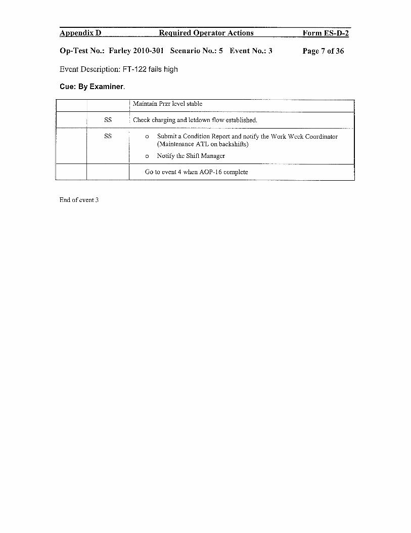
Appendix D Required Operator Actions Form ES-D-2
Op-Test No.: Farley 201 0-301 Scenario No.: 5 Event No.: 3 Page 7 of 36
Event Description: FT-122 fails high
Cue: By Examiner.
Maintain Przr level stable
SS Check charging and letdown flow established.
SS o Submit a Condition Report and notify the Work Week Coordinator(Maintenance ATL on backshifts)
o Notify the Shift Manager
Go to event 4 when AOP- 16 complete
End of event 3
Appendix D Required Operator Actions Form ES-D-2
Op-Test No.: Farley 2010-301 Scenario No.: 5 Event No.: 3 Page 7 of36
Event Description: FT-122 fails high
Cue: By Examiner.
Maintain Przr level stable
SS Check charging and letdown flow established.
SS 0 Submit a Condition Report and notify the Work Week Coordinator (Maintenance A TL on backshifts)
0 Notify the Shift Manager
Go to event 4 when AOP-16 complete
End of event 3

Appendix B Required Operator Actions Form ES-D-2
Op-Test No.: Farley 2010-301 Scenario No.: 5 Event No.: 4 Page 8 of 36
Event Description: 1A SG Tube leak — 25 gpm stabilizes in 5 minutes
Cue: By Examiner.
Time Position Applicant’s Action or Behavior
Annunciators: Recognize indications of SG TUBE LEAK
SG TUBE LEAK ABOVE SETPT (FG1) - R-15, 19 AND 23 IN ALARM
RMS HI RAD (FH1) - R-70A READING> 1000 GPD
SGBDPROCPNLTRBL(JB5)
FG1 and FH 1 actions
BOP Reference ARP and check R-70s to determine SG in alarm.
SS - Notify Chemistry of the alarm condition
- Direct entry into AOP-2
BOP Check ARP FH1 for actions as Rad monitors come into alarm.
- Do not allow personnel to enter the affected area without the approval ofthe Health Physics Department.
SS IF R-15 alarms AND remains above the alarm setpoint (not a momentaryspike), THEN perform the following:
- IF high effluent activity is possible, THEN implement EIP-9.0, ACTIONS.Call SM
- Notify the Counting Room to immediately sample the SGs per CCP-3 1 todetermine the leak rate.
- Notify the Operations Shift Manager.
j R-19 alarms refer to SOP-45.0 for guidance in sampling SGs with. R-19 inalarm.
IF R-23A OR R-23B alarms contact the RAD man to verify SGBD secured.
SS Direct entry and actions of AOP-2.0
RO Maintain pressurizer level stable at normal programmed value by:
- Control charging FK-122 adjusted as required
- Reduce letdown close one or more orifice isol. Valves
RO Maintain VCT level greater than 20%. by:
Verify RMW system in AUTO
OR
Manually control makeup as required by using SOP-2.3
Appendix D Required Operator Actions Form ES-D-2
Op-Test No.: Farley 2010-301 Scenario No.: 5 Event No.: 4 Page 8 of 36
Event Description: lA SG Tube leak - 25 gpm stabilizes in 5 minutes
Cue: By Examiner.
Time Position Applicant's Action or Behavior
Annunciators: Recognize indications of SG TUBE LEAK
- SG TUBE LEAK ABOVE SETPT (FG 1) - R-1S, 19 AND 23 IN ALARM
- RMS HI RAD (FH1) - R-70A READING> lOOO GPD
- SGBD PROC PNL TRBL (JBS)
FG 1 and FH 1 actions
BOP Reference ARP and check R-70s to determine SG in alarm.
SS - Notify Chemistry of the alarm condition
- Direct entry into AOP-2
BOP Check ARP FHI for actions as Rad monitors come into alarm.
- Do not allow personnel to enter the affected area without the approval of the Health Physics Department.
SS IF R-15 alarms AND remains above the alarm setpoint (not a momentary spike), THEN perfOlm the following:
- IF high effluent activity is possible, THEN implement EIP-9.0, ACTIONS. Call SM
- Notify the Counting Room to immediately sample the SGs per CCP-31 to determine the leak rate.
- Notify the Operations Shift Manager.
IF R-19 alarms refer to SOP-4S.0 for guidance in sampling SGs with R-19 in alarm.
IF R-23A OR R-23B alalms contact the RAD man to verify SGBD secured.
SS Direct entry and actions of AOP-2.0
RO Maintain pressurizer level stable at normal programmed value by:
- Control charging FK-122 adjusted as required
- Reduce letdown close one or more orifice isoI. Valves
RO Maintain VCT level greater than 20%. by:
Verify RMW system in AUTO
OR
Manually control makeup as required by using SOP-2.3

Appendix D Required Operator Actions Form ES-D-2
Op-Test No.: Farley 2010-301 Scenario No.: 5 Event No.: 4 Page 9 of 36
Event Description: 1A SG Tube leak — 25 gpm stabilizes in 5 minutes
Cue: By Examiner.
BOP Check that the Continuous Radiation Monitoring System is operable
Either R-15- OPERABLE
OR
R-70s- OPERABLE YES
SS Check reactor power conditions:
- Check NO power ascension in progress
- Check NO power reduction in progress
- Check reactor power greater than 20% YES to all
BOP Monitor primary to secondary leakage
Check R-70s or R-15 for increasing count rate YES
Begin trending R-70A and R- 15 using the plant computer and
Data sheet 1.
BOP Call TBSO to place SJAE filtration on service.
SS - Direct chemistry to perform grab samples and leak rate determinations.
CCP-201 Table 55
- Notify SM of leak rate
- Evaluate Step 10 table to determine appropriate response:
- ACTION LEVEL 4
30 gpdlhr rate of increase AND 75 gpd leak in any SG
Step 1 1 actions:
Check any two of the following rad monitors trending in the same direction:
- R-70s/R-15 OR R-70s/R-23A(B) OR R-15/R-23A(B)
- trending in the same direction with the same order of magnitude
SS - Direct reducing power to 50% rated thermal power within 1 hour
and place the Unit in Mode 3 within the next 2 hours. (3 hrs total)
- Identify the correct leaking SG 1A SG
Using R-70s, R-60s and level rise in any SG
Appendix D Required Operator Actions Form ES-D-2
Op-Test No.: Farley 2010-301 Scenario No.: 5 Event No.: 4 Page 9 of 36
Event Description: IA SG Tube leak - 25 gpm stabilizes in 5 minutes
Cue: By Examiner.
BOP Check that the Continuous Radiation Monitoring System is operable
Either R-15- OPERABLE
OR
R-70s- OPERABLE YES
SS Check reactor power conditions:
- Check NO power ascension in progress
- Check NO power reduction in progress
- Check reactor power greater than 20% YES to all
BOP Monitor primary to secondary leakage
Check R-70s or R-15 for increasing count rate YES
Begin trending R-70A and R-15 using the plant computer and
Data sheet 1.
BOP Call TBSO to place SJAE filtration on service.
SS - Direct chemistry to perform grab samples and leak rate determinations.
CCP-201 Table 55
- Notify SM of leak rate
- Evaluate Step 10 table to determine appropriate response:
- ACTION LEVEL 4
:2:30 gpdJhr rate of increase AND :2:75 gpd leak in any SG
Step 11 actions:
Check any two of the following rad monitors trending in the same direction:
- R-70s/R-15 OR R-70s/R-23A(B) OR R-15/R-23A(B)
- trending in the same direction with the same order of magnitude
SS - Direct reducing power to :::;50% rated thermal power within 1 hour
and place the Unit in Mode 3 within the next 2 hours. (3 hrs total)
- Identify the comct leaking SG lASG
Using R-70s, R-60s and level rise in any SG

Appendix D Required Operator Actions Form ES-D-2
Op-Test No.: Farley 2010-301 Scenario No.: 5 Event No.: 4 Page 10 of 36
Event Description: 1A SG Tube leak — 25 gpm stabilizes in 5 minutes
Cue: By Examiner.
BOP - Commence the ramp to <50% power in the next 1 hour
- Calculates ramp speed WILL be in TURB MAN for ramp
Approx. 6 MW per mm ramp rate to get below 50% in one hour.
Will borate lAW SOP-2.3 either continuous or multiple boration
For continuous: Set up FK-1 13 in auto and start boration or JAW sop-2.3multiple borations.
The Reactor Makeup Control system has been previously aligned for Boration.. Position the MKUP MODE CONT SWITCH to START.. Verify proper boration operation by observing the following:üOn service boric acid pump started.MKUP TO CHG PUMP SUCTION HDR FCV1 13B opens.1BORIC ACID TO BLENDER FCV1 13A opens.[Boric acid flow is displayed on Fl-i 13 MAKEUP FLOW TOCHG/VCTIf continuous then boration will continue, if not then the following will be done:Verify the boration automatically stops when the boric acid batch integratorreaches its setpoint as follows:fl Boric acid flow returns to zero as displayed on FI-113 MAKEUP FLOW TOCHG/VCT.LIFCV113B closes.LIFCV113A closes
Possible SS Call SM to evaluate emergency classificationso ow
AOP-2.0 does not have a step to evaluate Tech Specs but the ARP FG1updoes. If the candidate does not apply tech specs, make this a follow upquestion.
Evaluates Tech Specs 3.4.13 mandatory LCO Condition B- be in mode 3 in 6hours.
RCS operational LEAKAGE shall be limited to 150 gallons per day primary tosecondary LEAKAGE through any one steam generator (SG).
BOP - Direct Chemistry to monitor the turbine building sump for activity
- Verify affected SG(s) atmospheric relief valve-ALIGNED
- Check affected SG atmospheric relief valve — CLOSED
BOP - Verify SGBD isolated from the JA SG- 7614A closed
- Check AS supplied from Unit 2 NO
Call SSS to align AS
Go to next event when the ramp is sufficient or when the actions of AOP-2 complete.
END — Event 4
Appendix D Required Operator Actions Form ES-D-2
Op-Test No.: Farley 2010-301 Scenario No.: 5 Event No.: 4 Page 10 of 36
Event Description: lA SG Tube leak - 25 gpm stabilizes in 5 minutes
Cue: By Examiner.
BOP - Commence the ramp to <50% power in the next 1 hour
- Calculates ramp speed WILL be in TURB MAN for ramp
Approx. 6 MW per min ramp rate to get below 50% in one hour.
Will borate lAW SOP-2.3 either continuous or multiple boration
For continuous: Set u12 FK -113 in auto and start boration or lAW so12-2.3 multi12le borations.
The Reactor Makeup Control system has been previously aligned for Boration.
• Position the MKUP MODE CONT SWITCH to START .
• Verify proper boration operation by observing the following: [JOn service boric acid pump started. [JMKUP TO CHG PUMP SUCTION HDR FCVI13B opens. [JBORIC ACID TO BLENDER FCVl13A opens. [JBoric acid flow is displayed on FI-I13 MAKEUP FLOW TO CHGIVCT If continuous then boration will continue, if not then the following will be done: Verify the boration automatically stops when the boric acid batch integrator reaches its setpoint as follows: [JBoric acid flow retums to zero as displayed on FI-113 MAKEUP FLOW TO CHGIVCT. [JFCVI13B closes. [JFCVl13A closes
Possible SS Call SM to evaluate emergency classifications follow
AOP-2.0 does not have a steQ to evaluate Tech SQecs but the ARP FGl up
does. If the candidate does not aQQly tech sQecs l make this a follow uQ question.
Evaluates Tech SQecs 3.4.13 mandatory LCO Condition B- be in mode 3 in 6 hours.
RCS operational LEAKAGE shall be limited to 150 gallons per day primary to secondary LEAKAGE through anyone steam generator (SG).
BOP - Direct Chemistry to monitor the turbine building sump for activity
- Verify affected SG(s) atmospheric relief valve-ALIGNED
- Check affected SG atmospheric relief valve - CLOSED
BOP - Verify SGBD isolated from the 1A SG- 7614A closed
- Check AS supplied from Unit 2 NO
Call SSS to align AS
Go to next event when the ramp is sufficient or when the actions of AOP-2 complete.
END-Event4

Appendix D Required Operator Actions Form ES-D-2
Op-Test No.: Farley 2010-301 Scenario No.: 5 Event No.: 5 Page 11 of 36
Event Description: PK-444A fails LOW; PORV- 444B fails open; can be isolated
Cue: By Examiner.
Time Position Applicant’s Action or Behavior
Annunciators: Recognize indications of PK-444A FAILNG LOW
- PRZR PRESSURE HI-LO (HC1) - PORV-444B open
- PRZR SAFETY VLV TEMP HI (HA4) - Przr pressure decreasing
- PRZR PORV TEMP HI (HA5) - All heaters OFF
- PRZR CONT PRESS OUTOUT HI (HD3) - All spray valves open
- REL VLV 444B/445A OPEN (HE 1)
RCS pressure will be decreasing due to sprays open and PORV 444B open.
AOP-l0O, Section 1.1
SS Direct entry into AOP-100.
RO - Verify RCS pressure is stable. NO
- Take manual control of the PK-444A. will not be able to
OR
- Take manual control of the spray valves and heaters and PORVs
- Close spray valves and PORV 444B and turn on heaters
PORV will NOT close on handswitch Close Block valve
SS Check RCS pressure stable or rising YES
Set control band for RCS pressure. 2220-2250 psig
SS Refer to Tech Specs for LCO requirements that exist:
3.4.1 for DNBR limits
Pressure will have dropped below 2209 psig
Mandatory LCO restore pressure in 2 hours
3.4.11 PORVs- PORV is stuck open and is NOT capable of being opened andclosed manually.
Cond B — Close the block valve w/i 1 hour and remove power w/i 1 hour andrestore to operable status w/i 72 hours.
SS - Notify the Shift Manager
SS - Refer to SOP-0.0, GENERAL INSTRUCTIONS TO OPERATIONS
Appendix D Required Operator Actions Form ES-D-2
Op-Test No.: Farley 2010-301 Scenario No.: 5 Event No.: 5 Page 11 of 36
Event Description: PK-444A fails LOW; PORV- 444B fails open; can be isolated
Cue: By Examiner.
Time Position Applicant's Action or Behavior
Annunciators: Recognize indications ofPK-444A FAILING LOW
- PRZR PRESSURE HI-LO (HCI) - PORV-444B open
- PRZR SAFETY VL V TEMP HI (HA4) - Przr pressure decreasing
- PRZR PORV TEMP HI (HAS) - All heaters OFF
- PRZR CONT PRESS OUTOUT HI (HD3) - All spray valves open
- REL VLV 444Bi44SA OPEN (HEI)
RCS pressure will be decreasing due to sprays open and PORV 444B open.
AOP-lOO, Section 1.1
SS Direct entry into AOP-lOO.
RO - Verify RCS pressure is stable. NO
- Take manual control of the PK-444A. will not be able to
OR
- Take manual control of the spray valves and heaters and PORVs
- Close spray valves and PORV 444B and tum on heaters
PORV will NOT close on handswitch Close Block valve
SS Check RCS pressure stable or rising YES
Set control band for RCS pressure. 2220-2250 psig
SS Refer to Tech Specs for LCO requirements that exist:
3.4.1 for DNBR limits
Pressure will have dropped below 2209 psig
Mandatory LCO restore pressure in 2 hours
3.4.11 PORVs- PORV is stuck open and is NOT capable of being opened and closed manually.
Cond B - Close the block valve wii I hour and remove power wli I hour and restore to operable status wii 72 hours.
SS - Notify the Shift Manager
SS - Refer to SOP-O.O, GENERAL INSTRUCTIONS TO OPERATIONS

Appendix D Required Operator Actions Form ES-D-2
Op-Test No.: Farley 2010-301 Scenario No.: 5 Event No.: 5 Page 12 of 36
Event Description: PK-444A fails Low; PORV- 444B fails open; can be isolated
Cue: By Examiner.
PERSONNEL, for reporting requirements
Refer to FNP-1-SOP-l.2, REACTOR COOLANT PRESSURE RELIEFSYSTEM, for cooldown of the pressurizer relief tank.
Safety Valve. Relief Valve, and Reactor Vessel Head Vent Valve Failures amChallenges {CMTs 0007870, 0009924, 0005780, 0007544}
30.1 In order to comply with NRC reporting requirements, an LCOand condition report must be filled out each time one of thefollowing valves becomes inoperable or lifts
. Pressurizer power operated relief or safety valve
. Steam generator power operated relief or safety valve
30.2 Additionally due to pipe stress and hanger concerns anengineering evaluation is required if a reactor vessel head ventpath is established with RCS pressure greater than 400 psig.The condition report should contain at least the followinginformation:
• Which safety or power operated relief lifted or wasinoperable.
• Reactor power level.
. RCS temperature and pressure.
• Steam generator level and pressure.
. Approximately how long the valve was open.
SS Submit a Condition Report and notify the Work Week Coordinator(Maintenance ATL on backshifts
End event 5
Appendix D Required Operator Actions Form ES-D-2
Op-Test No.: Farley 2010-301 Scenario No.: 5 Event No.: 5 Page 12 of 36
Event Description: PK-444A fails LOW; PORV- 444B fails open; can be isolated
Cue: By Examiner.
PERSONNEL, for reporting requirements
Refer to FNP-1-S0P-1.2, REACTOR COOLANT PRESSURE RELIEF SYSTEM, for coo1down of the pressurizer relief tank.
Safety Valve Relief Valve and Reactor Vessel Head Vent Valve Failures and Challenges {CMTsOO07870,0009924,0005780,0007544}
30.1 In order to comply with NRC reporting requirements, an LCO and condition report must be filled out each time one of the following valves becomes inoperable or lifts
• Pressurizer power operated relief or safety valve
• Steam generator power operated relief or safety valve
30.2 Additionally due to pipe stress and hanger concems an engineering evaluation is required if a reactor vessel head vent path is established with RCS pressure greater than 400 psig. The condition report should contain at least the following information:
• Which safety or power operated relieflifted or was inoperable.
• Reactor power level.
• RCS temperature and pressure.
• Steam generator level and pressure.
• Approximately how long the valve was open .
SS Submit a Condition Report and notify the Work Week Coordinator (Maintenance A TL on backshifts
End event 5

Appendix B Required Operator Actions Form ES-B-2
Op-Test No.: Farley 2010-301 Scenario No.: 5 Event No.: 6 Page 13 of 36
Event Description: PT-486 fails LOW
Cue: By Examiner
Time Position Applicant’s Action or Behavior
Annunciators: Recognize indications of PT-486 failing:
SO LVL DEV (JF2) - lB SO water level decreasing
lB SO STM LiNE HI DP ALERT (JE2) - lB FRV going full closed
lB SO FEED FLOW> STM FLOW (102)
AOP-l00, section 1.5
SS Direct AOP-l00 entry and lOAs taken.
UO Immediate Actions for AOP- 100
. Take manual control of:
- FK-488 and raise controller to increase SOWL.
- Monitor SG Levels to recommend Reactor Trip if SO levels approach 28%
SS Establish Trip criteria if necessary
BOP Place ramp on HOLD
BOP Determine the instrument failure
BOP Select out the controlling channel by placing the following handswitches to theappropriate channel III OR IV position as required:
B SO STM FLOW SEL SW FS/488Z
B SO FW FLOW SEL SW .- FS/488Y
. Restore the FRV to automatic control
SS Refer to Tech Spec 3.3.2 function e (2) cond D; Place channel in trip in 72 hours or be in mode 3 in78 hours and mode 4 in 84 hours.
SF failing low based on PT-486 failing is NOT a TS action since the SF protection channel is notdensity compensated.
Tech Spec 3.3.3 cond A; ADMIN LCO
SS Notify the SM
SS Submit a condition report for the failed instrument, and notify the Notify theWork Week Coordinator (Maintenance ATL on backshifts)of the conditionreport
END — Event 6
Appendix D Required Operator Actions Form ES-D-2
Op-Test No.: Farley 2010-301 Scenario No.: 5 Event No.: 6 Page 13 of36
Event Description: PT -486 fails LOW
Cue: By Examiner
Time Position Applicant's Action or Behavior
Annunciators: Recognize indications ofPT-486 failing:
- SG LVL DEV (JF2) - IB SG water level decreasing
- 1B SG STM LINE HI DP ALERT (JE2) - 1B FRV going full closed
- 1B SG FEED FLOW> STM FLOW (JG2)
AOP-IOO, section 1.5
SS Direct AOP-lOO entry and IOAs taken.
UO Immediate Actions for AOP-IOO
• Take manual control of:
- FK-488 and raise controller to increase SGWL.
- Monitor SG Levels to recommend Reactor Trip ifSG levels approach 28%
SS Establish Trip criteria if necessary
BOP Place ramp on HOLD
BOP Determine the instrument failure
BOP Select out the controlling channel by placing the following handswitches to the appropriate channel III OR IV position as required:
B SG STM FLOW SEL SW - FS/488Z
B SG FW FLOW SEL SW - FS/488Y
• Restore the FRV to automatic control
SS Refer to Tech Spec 3.3.2 function e (2) cond D; Place channel in trip in 72 hOllrs or be in mode 3 in 78 hours and mode 4 in 84 hours.
SF failing low based on PT-486 failing is NOT a TS action since the SF protection channel is not density compensated.
Tech Spec 3.3.3 cond A; ADMIN LCO
SS Notify the SM
SS Submit a condition report for the failed instrument, and notify the Notify the Work Week Coordinator (Maintenance ATL on backshifts )of the condition report
END-Event 6

Appendix D Required Operator Actions Form ES-D-2
Op-Test No.: Fancy 2010-301 Scenario No.: 5 Event No.: 7/ 8 Page 14 of 36
Event Description: EH FLUID leak and subsequent trip of BOTH SGFPs; FRP-S. 1entered
Cue: By Examiner
Time Position Applicant’s Action or Behavior
Annunciators: Recognize indications of I a eh Fluid pump trip:
- EH FLUID SYS TRBL (KG1) - P1-4012, EH FLUID pressure decreasing
- DEH TRBL (LB 1) - Amber light on 1A EH Fluid pump handswitch
- EH FLUID LEVEL LO-LO (KG2) Recognize indications of ATWT event
- TURB TV CLOSED ALERT (KG4) - RTBs stifi closed
- iNTERCEPT OR REHT STOP VLV CLOSED - NIs indicate full power(KG5)
Conditions warrant a reactor trip and one is not- TURB AUTO-STOP OIL PRESS LO (KH5) received <28% SGWL NR
AOP-13 or ARP directs the reactor trip when a loss of Both SGFPs occur and the Main Turbine trips
When the crew tries to trip the reactor the reactor trip breakers will not open and the CRDM MG setbreakers will not open. 1A SG will rupture when 1A SG NR level drops to 20% or at step 5 of EEP-0.
SS Direct isolating leak and filling EH.
May direct a ramp to 55% power due to the leak.
BOP If directed, may decrease turbine load.
SS Establish Reactor trip criteria such as when SGWL NR is < 28% then trip thereactor.
When BOTH SGFPs trip, then direct the following:
SS Direct entry into EEP-0 — IOAs
RO/BOP Immediate Operator actions of EEP-0
Check reactor trip. NO
Check all reactor trip breakers and reactor trip bypass breakers - OPEN.
Check nuclear power - FALLING.
check rod bottom lights - LIT.
TRIP CRDM MG set supply breakers. NO
1A(1B)MGSETSUPPBKR
[] N1C11EOO5A
Appendix D Required Operator Actions Form ES-D-2
Op-Test No.: Farley 2010-301 Scenario No.: 5 Event No.: 7/8 Page 14 of36
Event Description: EH FLUID leak and subsequent trip of BOTH SGFPs; FRP-S.l entered
Cue: By Examiner
Time Position Applicant's Action or Behavior
Annunciators: Recognize indications of la eh Fluid pump trip:
- EH FLUID SYS TRBL (KG I) - PI-4012, EH FLUID pressure decreasing
- DEH TRBL (LBI) - Amber light on IA EH Fluid pump hands witch
- EH FLUID LEVEL LO-LO (KG2) Recognize indications of ATWT event
- TURB TV CLOSED ALERT (KG4) - RTBs still closed
- INTERCEPT OR REHT STOP VLV CLOSED - NIs indicate full power (KG5)
Conditions warrant a reactor trip and one is not - TURB AUTO-STOP OIL PRESS LO (KH5) received <28% SGWL NR
AOP-13 or ARP directs the reactor trip when a loss of Both SGFPs occur and the Main Turbine trips
When the crew tries to trip the reactor the reactor trip breakers will not open and the CRDM MG set breakers will not open. IA SG will rupture when IA SG NR level drops to 20% or at step 5 ofEEP-O.
SS Direct isolating leak and filling EH.
May direct a ramp to 55% power due to the leak.
BOP If directed, may decrease turbine load.
SS Establish Reactor trip criteria such as when SGWL NR is < 28% then trip the reactor.
When BOTH SGFPs trip, then direct the following:
SS Direct entry into EEP-O - IOAs
ROIBOP Immediate Operator actions ofEEP-O
Check reactor trip. NO
Check all reactor trip breakers and reactor trip bypass breakers - OPEN.
Check nuclear power - FALLING.
check rod bottom lights - LIT.
TRIP CRDM MG set supply breakers. NO
IA(IB) MG SET SUPP BKR
[] NICIIEOO5A

Appendix D Required Operator Actions Form ES-D-2
Op-Test No.: Farley 2010-301 Scenario No.: 5 Event No.: 7/ 8 Page 15 of 36
Event Description: EH FLUID leak and subsequent trip of BOTH SGFPs; FRP-S.1entered
Cue: By Examiner
[] N1C11E0O5B
Reactor is not tripped by RTBs or CRDM MG sets.
SS Direct entry into FRP S.1 and complete IOAs.
(Cl) RO Critical task
IF reactor still NOT tripped, THEN perform the following:
Insert control rods in manual control.
OR
Verify rods insert in AUTO at greater than 48 steps per minute.
Dispatch an operator to locally trip the reactor trip and bypass breakers.
3 minutes from this phone call RTBs will be opened from BOOTH
BOP Check Main Turbine tripped YES
Place MAIN TURB EMERG TRIP switch to TRIP for at least 5 seconds.
Then reduce GV position demand to zero from the DEH panel.
BOP Verify AFW pumps running
- Both MDAFWPs amps > 0
- TDAFWP speed> 3900 rpm
RO Initiate Emergency B oration of the RCS.
- Verify at least one CHG PUMP - RUNNING.
- Start a BAT pump
- OpenMOV 8104
- Establish normal letdwn flow — 8149A and either 8149B or C open
- Check RCS pressure less than 2335 psig
- Establish normal charging flow >40 gpm
- Verify adequate emergency boration flow of> 30 gpm on FT-lb
BOPVerify containment ventilation isolation.
Verify containment purge dampers - CLOSED.
[] 3197
[] 3198D
Appendix D Required Operator Actions Form ES-D-2
Op-Test No.: Farley 2010-301 Scenario No.: 5 Event No.: 7/8 Page 15 of36
Event Description: EH FLUID leak and subsequent trip of BOTH SGFPs; FRP-S.l entered
Cue: By Examiner
[] N1CllE005B
Reactor is not tripped by RTBs or CRDM MG sets.
SS Direct entry into FRP S.l and complete IOAs.
(CT) RO Critical task
IF reactor still NOT tripped, THEN perform the following:
Insert control rods in manual control.
OR
Verify rods insert in AUTO at greater than 48 steps per minute.
Dispatch an operator to locally trip the reactor trip and bypass breakers.
3 minutes from this phone call RTBs will be opened from BOOTH
BOP Check Main Turbine tripped YES
Place MAIN TURB EMERG TRIP switch to TRIP for at least 5 seconds.
Then reduce GV position demand to zero from the DEH panel.
BOP Verify AFW pumps running
- Both MDAFWPs amps> 0
- TDAFWP speed> 3900 rpm
RO Initiate Emergency Boration of the RCS.
- Verify at least one CHG PUMP - RUNNING.
- Start a BAT pump
- Open MOV 8104
- Establish normalletdwn flow - 8149A and either 8149B or Copen
- Check RCS pressure less than 2335 psig
- Establish normal charging flow> 40 gpm
- Verify adequate emergency boration flow of> 30 gpm on FI-II0
BOP Verify containment ventilation isolation.
Verify containment purge dampers - CLOSED.
[] 3197
[] 3198D

Appendix B Required Operator Actions Form ES-D-2
Op-Test No.: Farley 2010-301 Scenario No.: 5 Event No.: 7 / 8 Page 16 of 36
Event Description: ER FLUID leak and subsequent trip of BOTH SGFPs; FRP-S.1entered
Cue: By Examiner
[1 3198C
[] 3196
[] 3198A
[] 3198B
Verify containment mini purge dampers - CLOSED.
CTMT PURGE DMPRS
MINI-2866C & 2867C
FULL-3198A & 3198D
[] 2866C
[] 2867C
CTMT PURGE DMPRS
MINI-2866D & 2867D
FULL-3196 & 3197
BOTH-3198B & 3198C
[] 2866D
[] 2867D
Stop MINI PURGE SUPP/EXH FAN. Will place uS to STOP
BOP Check SI actuated — complete attachment 1
See attached sheets for Attachment 1 of FRP-S.1
RO - Check ALL RTBs open
- Check Main Turbine tripped
RO [CA] Check if reactor still critical.
If RTBs are open or power range indication is < 5% power OR JR SUR isnegative, then go to EEP-O step 1
SS Transition back to EEP-O
RO/BOP Immediate Operator actions of EEP-O
Check reactor trip.
Check all reactor trip breakers and reactor trip bypass breakers - OPEN.
Check nuclear power - FALLING.
Appendix D Required Operator Actions Form ES-D-2
Op-Test No.: Farley 2010-301 Scenario No.: 5 Event No.: 7/8 Page 16 of36
Event Description: EH FLUID leak and subsequent trip of BOTH SGFPs; FRP-S.l entered
Cue: By Examiner
[]3198C
[] 3196
[] 3198A
[] 3198B
Verify containment mini purge dampers - CLOSED.
CTMT PURGE DMPRS
MINI-2866C & 2867C
FULL-3198A & 3198D
[] 2866C
[] 2867C
CTMT PURGE DMPRS
MINI-2866D & 2867D
FULL-3196 & 3197
BOTH-3198B & 3198C
[] 2866D
[] 2867D
Stop MINI PURGE SUPP/EXH FAN. Will place HS to STOP
BOP Check SI actuated - complete attachment 1
See attached sheets for Attachment 1 of FRP-S.l
RO - Check ALL RTBs open
- Check Main Turbine tripped
RO [CA] Check ifreactor still critical.
If RTBs are open or power range indication is < 5% power OR IR SUR is negative, then go to EEP-O step 1
SS Transition back to EEP-O
ROIBOP Immediate Operator actions ofEEP-O
Check reactor trip.
Check all reactor trip breakers and reactor trip bypass breakers - OPEN.
Check nuclear power - FALLING.

Appendix D Required Operator Actions Form ES-D-2
Op-Test No.: Farley 2010-301 Scenario No.: 5 Event No.: 7 / 8 Page 17 of 36
Event Description: EH FLUID leak and subsequent trip of BOTH SGFPs; FRP-S.1entered
Cue: By Examiner
check rod bottom lights - LIT.
Check turbine - TRIPPED.
TSLB2 14-1 thru4 lit
Check power to 4160 V ESF busses.
4160 V ESF busses - AT LEAST ONE ENERGIZED
A Train (F & K) power available lights lit
OR
B Train (G & L) power available lights lit
Verify operating diesel generators are being supplied from at least one SWpump.
Check SI Status. YES
Check any SI actuated indication.
BYP & PERMISSIVE SAFETY INJECTION
{] ACTUATED status light lit
[J MLB-1 1-1 lit
{]IvILB—1 11—1 lit
If YES will continue IN EEP-0 step 5
IF NO then will go to ESP-0. 1
THE SGTR will be put in at this point if it is not already in by trigger 2
Directs continuing into EEP-0 at step 5.
Directs the BOP to do attachment 2.
See Tab at end of scenario Attaclm-ient 2 and 4 for actions
Appendix D Required Operator Actions Form ES-D-2
Op-Test No.: Farley 2010-301 Scenario No.: 5 Event No.: 7/8 Page 17 of36
Event Description: EH FLUID leak and subsequent trip of BOTH SGFPs; FRP-S.l entered
Cue: By Examiner
check rod bottom lights - LIT.
Check turbine - TRIPPED.
TSLB2 14-1 thru 4 lit
Check power to 4160 V ESF busses.
4160 V ESF busses - AT LEAST ONE ENERGIZED
A Train (F & K) power available lights lit
OR
B Train (G & L) power available lights lit
Verify operating diesel generators are being supplied from at least one SW pump.
Check SI Status. YES
Check any SI actuated indication.
BYP & PERMISSIVE SAFETY INJECTION
[] ACTUATED status light lit
[] MLB-l 1-1 lit
[] MLB-l 11-1 lit
If YES will continue IN EEP-O step 5
IF NO then will go to ESP-O.l
THE SGTR will be Qut in at this Qoint if it is not already in by trigger 2
SS Directs continuing into EEP-O at step 5.
Directs the BOP to do attachment 2.
See Tab at end of scenario Attachment 2 and 4 for actions

Appendix B Required Operator Actions Form ES-D-2
Op-Test No.: Farley 2010-301 Scenario No.: 5 Event No.: 7/ 8 Page 18 of 36
Event Description: EH FLUID leak and subsequent trip of BOTH SGFPs; FRP-S.1entered
Cue: By Examiner
RO[CA] Check containment pressure- HAS
REMAINED LESS THAN 27 psig YES
RO ,, . .
Announce Unit 1 reactor trip and safety injection”.
RCheck AFW status.
Check secondary heat sink Available
o Check total AFW flow> 395 gpm
[]FI 3229A
[]Fl 3229B
[]Fl 3229C
o Total Flow Fl 3229
OR
Check any SG NR level> 31% {48%}
WHEN all SG narrow range levels less than 3 1%{48%},
THEN maintain total AFW flow greater than 395 gpm.
WHEN at least two SG narrow range levels greater than 28%
AND TDAFWP NOT required, THEN stop TDAFWP.
[CA] WHEN SG narrow range level greater than 31% {48%},
THEN maintain SG narrow range level 31%-65%{48%-65%}.
Control MDAFWP flow.
MDAFWP FCV 3227 RESET
[]A TRN reset
[]B TRN reset
MDAFWP TO lA/lB/iC SG
B TRN
[]FCV 3227 in MOD
Appendix D Required Operator Actions Form ES-D-2
Op-Test No.: Farley 2010-301 Scenario No.: 5 Event No.: 7/8 Page 18 of36
Event Description: EH FLUID leak and subsequent trip of BOTH SGFPs; FRP-S.l entered
Cue: By Examiner
RO [CAl Check containment pressure- HAS
REMAINED LESS THAN 27 psig YES
RO Announce "Unit 1 reactor trip and safety injection".
RO Check AFW status.
Check secondary heat sink Available
0 Check total AFW flow> 395 gpm
[] FI 3229A
[] FI 3229B
[] FI 3229C
0 Total Flow FI 3229
OR
Check any SG NR level> 31 % {48%}
WHEN all SG narrow range levels less than 31 % {48%},
THEN maintain total AFW flow greater than 395 gpm.
WHEN at least two SG narrow range levels greater than 28%
AND TDAFWP NOT required, THEN stop TDAFWP.
[CA] WHEN SG narrow range level greater than 31 % {48%},
THEN maintain SG narrow range level 31 %-65% {48%-65%}.
Control MDAFWP flow.
MDAFWP FCV 3227 RESET
[] A TRN reset
[] B TRN reset
MDAFWP TO 1Ai1B/1C SG
BTRN
[] FCV 3227 in MOD

Appendix D Required Operator Actions Form ES-D-2
Op-Test No.: Fancy 2010-301 Scenario No.: 5 Event No.: 7 / 8 Page 19 of 36
Event Description: EH FLUID leak and subsequent trip of BOTH SGFPs; FRP-S.1entered
Cue: By Examiner
Control TDAFWP flow.
TDAFWP FCV 3228
[1 RESET reset
TDAFWP SPEED CONT
[] SIC 3405 adjusted
ROCheck RCS temperature.
IF any RCP running, THEN check RCS average temperature .. STABLE AT ORAPPROACHING 547°F.
TAVG 1A(1B,1C) RCS LOOP
[]T1412D
[]T1422D
[1 TI 432D
RORNO
IF RCS temperature less than 547°F and falling, THEN perform the following.
Verify steam dumps closed.
STM DUMP INTERLOCK
[]A TRN in OFF RESET
[J B TRN in OFF RESET
Verify atmospheric reliefs closed on MCB Demand at 0 andminimum red light LIT
Control total AFW flow to minimize RCS cooldown,
AFW FLOW TO 1A(1B,1C) SG
[]FI 3229A
[1 Fl 3229B
[]Fl 3229C
AFW TOTAL FLOW
[]Fl 3229
IF MSIVs are open, THEN isolate steam loads in the turbine building
Call TBSO to isolate steam loads
Appendix D Required Operator Actions Form ES-D-2
Op-Test No.: Farley 2010-301 Scenario No.: 5 Event No.: 7/8 Page 19 of 36
Event Description: EH FLUID leak and subsequent trip of BOTH SGFPs; FRP-S.l entered
Cue: By Examiner
Control TDAFWP flow.
TDAFWP FCV 3228
[] RESET reset
TDAFWP SPEED CONT
[] SIC 3405 adjusted
RO Check RCS temperature.
IF any RCP running, THEN check RCS average temperature - STABLE AT OR APPROACHING 547°F.
TAVG lA(lB,lC) RCS LOOP
[] TI412D
[] TI 422D
[] TI 432D
RO RNO
IF RCS temperature less than 547°F and falling, THEN perfoll1 the following.
Verify steam dumps closed.
STM DUMP INTERLOCK
[] A TRN in OFF RESET
[] B TRN in OFF RESET
Verify atmospheric reliefs closed on MCB Demand at 0 and minimum red light LIT
Control total AFW flow to minimize RCS cooldown,
AFW FLOW TO lA(lB,lC) SG
[] FI 3229A
[] FI 3229B
[] FI3229C
AFW TOTAL FLOW
[] FI 3229
IF MSIV s are open, THEN isolate steam loads in the turbine building
Call TBSO to isolate steam loads

Appendix D Required Operator Actions Form ES-D-2
Op-Test No.: Farley 2010-301 Scenario No.: 5 Event No.: 7/ 8 Page 20 of 36
Event Description: EH FLUID leak and subsequent trip of BOTH SGFPs; FRP-S. 1entered
Cue: By Examiner
IF cooldown continues, THEN close MSIVs and MSIV bypass valves.
Verify ALL MSIVs closed
IF main steam lines isolated AND gland steam supplied from Unit 1,
THEN break condenser vacuum.
Call TBSO to open COND VAC BKR MAN ISO
/ RO Check pressurizer PORVs and spray valves.
WHEN pressurizer pressure less than 2335 psig, THEN verify both PRZRPORV’s closed.
Verify both PRZR PORVs indicate CLOSED YESClose MOV8000A
10.1.2 Check PRZR PORV temperature STABLE OR FALLiNG.[] PORV Temp TI-463
10.1.3 Check PRT parameters STABLE or FALLING. YES[] PRT PRESS P1 472[] PRT LVL LI-470[] PRT TEMP TI-47 1
10.2 [CA] WHEN pressurizer pressure less than 2260 psig, THEN verify normalpressurizer spray valves closed OR in the process of closing.
1A(1B) LOOP SPRAY VLV YES[] PK 444C[] PK 444D
10.3 Check any PRZR PORV ISO — OPEN YES
RO 11 Check RCP criteria.11.1 Check SUB COOLED MARGIN 1 1.1 IF HHSI flow greater thanMONITOR indication - GREATER 0 gpm, THEN stopTHAN 16°F{45°F} SUBCOOLED IN all RCPs.CETC MODE
RO 12 Monitor charging pump miniflow criteria.12.1 Control charging pump miniflow valves based on RCS pressure.1C(1A) LOOP RCS WR PRESS
[] PT 402A[1 P1403A
Appendix D Required Operator Actions Form ES-D-2
Op-Test No.: Farley 2010-301 Scenario No.: 5 Event No.: 7/8 Page 20 of36
Event Description: EH FLUID leak and subsequent trip of BOTH SGFPs; FRP-S.l entered
Cue: By Examiner
IF cooldown continues, THEN close MSIVs and MSIV bypass valves.
Verify ALL MSIV s closed
IF main steam lines isolated AND gland steam supplied from Unit 1,
THEN break condenser vacuum.
Call TBSO to open COND V AC BKR MAN ISO
SS/RO Check pressurizer PORVs and spray valves.
WHEN pressurizer pressure less than 2335 psig, THEN verify both PRZR PORV's closed.
Verify both PRZR PORV s indicate CLOSED YES Close MOV8000A
10.1.2 CheckPRZR PORV temperature STABLE OR FALLING. [] PORV Temp TI-463
10.1.3 Check PRT parameters STABLE or FALLING. YES [] PRT PRESS PI 472 [] PRT LVL LI-470 [] PRT TEMP TI-471
10.2 [CA] WHEN pressurizer pressure less than 2260 psig, THEN verify normal pressurizer spray valves closed OR in the process of closing.
lA(lB) LOOP SPRAY VLV YES [] PK444C [] PK444D
10.3 Check any PRZR PORV ISO - OPEN YES
RO 11 Check RCP criteria. 11.1 Check SUB COOLED MARGIN 11.1 IF HHSI flow greater than MONITOR indication - GREATER o gpm, THEN stop THAN 16°F{45°F} SUB COOLED IN all RCPs. CETCMODE
RO 12 Monitor charging pump miniflow criteria. 12.1 Control charging pump miniflow valves based on RCS pressure. 1C(lA) LOOP RCS WR PRESS [] PI402A [] PI403A

Appendix D Required Operator Actions Form ES-D-2
Op-Test No.: Farley 2010-301 Scenario No.: 5 Event No.: 7 I 8 Page 21 of 36
Event Description: EH FLUID leak and subsequent trip of BOTH SGFPs; FRP-S.1entered
Cue: By Examiner
Based on RCS pressure, close miniflows < 1300 and open when> 1900psig.
SS 13 Check SGs not faulted. NO SG Faultedo Check no SG pressure - FALLING IN AN UNCONTROLLED
MANNER OR LESS THAN 50 psig.
SS 14 Check SGs not ruptured. YES lB SG Rupturedo Check secondary radiation indication - NORMAL.
Checks rad monitors R-15, 19, 23A and B, 15B and C, and 60 A, B, C, Do No SG level rising in an uncontrolled manner.
End of event 7/8
Appendix D Required Operator Actions Form ES-D-2
Op-Test No.: Farley 2010-301 Scenario No.: 5 Event No.: 7/8 Page 21 of 36
Event Description: EH FLUID leak and subsequent trip of BOTH SGFPs; FRP-S.l entered
Cue: By Examiner
Based on RCS pressure, close mini flows < 1300 and open when> 1900 pSlg.
SS 13 Check SGs not faulted. NO SG Faulted 0 Check no SG pressure - FALLING IN AN UNCONTROLLED
MANNER OR LESS THAN 50 psig.
SS 14 Check SGs not ruptured. YES 1B SG Ruptured 0 Check secondary radiation indication - NORMAL.
Checks rad monitors R-15, 19, 23A and B, 15B and C, and 60 A, B, C, D 0 No SG level rising in an uncontrolled manner.
End of event 7/8

Appendix D Required Operator Actions Form ES-D-2
Op-Test No.: Farley 2010-301 Scenario No.: 5 Event No.: 9 /10 Page 22 of 36
Event Description: lB SGTR 500 gpm
Cue: Preset or at step 5 of EEP-0
Time Position Applicant’s Action or Behavior
EEP-3, SGTR entered from EEP-O
RO Check RCP criteria.
Check SUB COOLED MARGIN MONITOR indication - GREATER THAN16°F{45°F} SUBCOOLED INCETC MODE YES
BOP [CAl Identify ruptured SG(s).
Check any SG level - RISING iN AN UNCONTROLLED MANNERYES- lB SG
SS/RO Critical task
[CAl WHEN ruptured SG(s) identified, THEN isolate flow from rupturedSG(s).
Verify ruptured SG(s) atmospheric relief valve - ALIGNED.
- PC3371B set 8.25 and in auto
- Verify 3371B is closed YES
Isolate steam supply from ruptured SG(s) to TDAFWP:
- Direct counting room to perform CCP-645, MAIN STEAM ABNORMALENVIRONMENTAL RELEASE.
- Check at least one MDAFWP running AND no TDAFWP auto
start signals present. YES one MDAFWP runningand no auto start signals in
- Stop the TDAFWP from the main control board.
TDAFWP STM SUPP FROM 1B(1C) SG
[]Q1N12HV3235A/26 stopped
[]Q1N12HV3235B stopped
TDAFW SPEED CONT
[]SIC 3405 at 0%
Check TDAFWP steam supply valves closed.
TDAFWP STM SUPP FROM 1B(1C) SG
Appendix D Required Operator Actions Form ES-D-2
Op-Test No.: Farley 2010-301 Scenario No.: 5 Event No.: 9 /10 Page 22 of36
Event Description: IB SGTR 500 gpm
Cue: Preset or at step 5 of EEP-O
Time Position Applicant's Action or Behavior
EEP-3, SGTR entered from EEP-O
RO Check RCP criteria.
BOP
SS/RO
Check SUB COOLED MARGIN MONITOR indication - GREATER THAN l6°F {45°F} SUB COOLED INCETC MODE YES
rCA) Identify ruptured SG(s).
Check any SG level - RISING IN AN UNCONTROLLED MANNER YES-lB SG
Critical task
rCA) WHEN ruptured SG(s) identified, THEN isolate flow from ruptured SG(s).
Verify ruptured SG(s) atmospheric relief valve - ALIGNED.
PC3371B set 8.25 and in auto
- Verify 3371B is closed YES
Isolate steam supply from ruptured SG(s) to TDAFWP:
- Direct counting room to perform CCP-645, MAIN STEAM ABNORMAL ENVIRONMENTAL RELEASE.
- Check at least one MDAFWP running AND no TDAFWP auto
start signals present. YES one MDAFWP running and no auto start signals in
- Stop the TDAFWP from the main control board.
TDAFWP STM SUPP FROM 1B(lC) SG
[] QlNl2HV3235A126 stopped
[] QlNl2HV3235B stopped
TDAFW SPEED CONT
[] SIC 3405 at 0%
Check TDAFWP steam supply valves closed.
TDAFWP STM SUPP FROM lB(lC) SG

Appendix D Required Operator Actions Form ES-D-2
Op-Test No.: Farley 2010-301 Scenario No.: 5 Event No.: 9 /10 Page 23 of 36
Event Description: lB SGTR 500 gpm
Cue: Preset or at step 5 of EEP-0
[]MLB-4 1-3 not lit
[]MLB-4 2-3 not lit
[]MLB-4 3-3 not lit
Verify blowdown from ruptured SG(s) - ISOLATED.
Closes 7614B
Verify at least one SG MSIV on lB SO closed
Closes MSIV 3369B or 3370B closed
(CT)and bypass valves closed
BOP [CA] WHEN ruptured SG(s) NR level greater than 31% THEN performthe following:
[CA] Isolate AFW flow to ruptured SG(s) using FCVs.
- FCV 3227B in MOD, and closed YES
- HV 3328B in MOD and closed YES
SS Check ruptured SG(s) pressure GREATER THAN 250 psig.YES
SS Evaluate performing an RCS cooldown.
Determine required CETCs for cooldown based on ruptured SO pressure.
Appendix D Required Operator Actions Form ES-D-2
Op-Test No.: Farley 2010-301 Scenario No.: 5 Event No.: 9 /10 Page 23 of 36
Event Description: IB SGTR 500 gpm
Cue: Preset or at step 5 of EEP-O
[] MLB-4 1-3 not lit
[] MLB-4 2-3 not lit
[] MLB-4 3-3 not lit
Verify blowdown from ruptured SG( s) - ISOLA TED.
Closes 7614B
Verify at least one SG MSIV on 1B SG closed
Closes MSIV 3369B or 3370B closed
(CT) and bypass valves closed
BOP [CAl WHEN ruptured SG(s) NR level greater than 31 % THEN perform the following:
rCA] Isolate AFW flow to ruptured SG(s) using FCVs.
- FCV 3227B in MOD, and closed YES
- HV 3328B in MOD and closed YES
SS Check ruptured SG(s) pressure GREATER THAN 250 psig. YES
SS Evaluate performing an RCS cooldown.
Determine required CETCs for cooldown based on ruptured SG pressure.

Appendix D Required Operator Actions Form ES-D-2
Op-Test No.: Farley 2010-301 Scenario No.: 5 Event No.: 9 / 10 Page 24 of 36
Event Description: lB SGTR 500 gpm
Cue: Preset or at step 5 of EEP-0
RUPTUREDSC
PRESSURE(pig)
1151 - 12001101 - 11501051 - 11001001 - 1050
951 - 1000901 - 950851 - 900801 - 850751 - 800701 - 750651 - 700601 - 650551 - 600501 - 550451 - 500401 - 450351 - 400301 - 350251 - 300
- 250
REQUIREDCOREEXIT
TEMPERATURE
536°F 1522°F)531°F 1516°F)525°F 1510°F)519F {504°F)513°F 1498°F)507°F 1491°F)500°F 1484°F)494°F {477°F)487°F {46g0F)
479°F 1461°F)471°F 1453°F)463°F {443°Fj454°F 1434°F)445°F t423°Fj434°F 1412°F)423°F (400°F)411°F (386°F)398°F (370°F)383°F {33°F)365°F {332°F)
SS Direct the STA to Display the hottest CETC page 1TC1 on plant computer.
This is normally selected by the STA and put on the control board display.
SRO Will direct the BOP to perform the steps below:The Steam Dumps are available.
Critical task
(CT) - Dump steam at the maximum attainable rate from INTACT SGs
WHEN P-12 light lit (543F), THEN perform the following.BOP Block low steam line pressure SI.
STM LINE PRESS SI BLOCK - RESET
[] A TRN to BLOCK
Appendix D Required Operator Actions Form ES-D-2
Op-TestNo.: Farley20l0-30l ScenarioNo.:5 EventNo.:9 110 Page24of36
Event Description: IB SGTR 500 gpm
Cue: Preset or at step 5 of EEP-O
(CT)
RUPTURED REQUIRED SG CORE
PRESSURE EXIT (psig) TEMPERATURE
1151 - 1200 5361)F {522°F) 1101 - 1150 531°F {516I)F) 1051 - 1100 52SI)F {S10°F) 1001 - 1050 519°F {S04°F}
951 - 1000 5131)F {498I)F} 901 - 950 507°F {491°F) 851 - 900 500l)F {484°F) 801 - 850 494°F {477°F) 751 - 800 48rF {469°F} 701 - 750 4791)F {46P~F}
451 - 500 434°F 412°F 401 - 450 4231)F {400°F} 351 - 400 411°F {386°F} 301 - 350 398°F {370°F) 251 - 300 3831)F {J53°P)
250 36SI)F {332°F}
SS Direct the STA to Display the hottest CETC page 1 TCl on plant computer.
This is normally selected by the STA and put on the control board display.
SRO Will direct the BOP to perform the steps below:
BOP
The Steam Dumps are available.
Critical task Dump steam at the maximum attainable rate from INTACT SGs
WHEN P-12 light lit (543F), THEN perform the following. Block low steam line pressure S1. STM LINE PRESS SI BLOCK - RESET [] A TRN to BLOCK

Appendix D Required Operator Actions Form ES-D-2
Op-Test No.: Farley 2010-301 Scenario No.: 5 Event No.: 9 /10 Page 25 of 36
Event Description: lB SGTR 500 gpm
Cue: Preset or at step 5 of EEP-0
[] B TRN to BLOCK
Verify blocked indication.BYP & PERMISSIVESTM LINE ISOL. SAFETY 1NJ.[]TRA1N A BLOCKED light lit[]TRAIN B BLOCKED light lit
Bypass the steam dump interlock.STM DUMP INTERLOCK
[j A TRN to BYP INTLK{] B TRN to BYP INTLK
Adjust steam header pressure controller to maximize cooldown rate.LI STM HDR PRESS PK 464 adjusted
BOP IF condenser available, THEN dump steam to condenser from intact SGsat maximum attainable rate.
BYP & PERMISSIVE COND AVAIL[] C—9 light lit
STM DUMP[]MODE SEL A-B TRN in STM PRESS
STM DUMP INTERLOCK
[1 A TRN in ON[]B TRN in ON
STM HDR PRESS{] PK 464 adjusted
Check hottest core exit T/Cs LESS THAN REQUIREDTEMPERATURE.
BOP Stop the cooldown when the hottest CETC temperature is less than therequired temperature and then maintain CETCs at the required Temp.
BOP Check intact SG levels.
Check any intact SG narrow range level — YES
GREATER THAN 31%{48%}.
[CA] WHEN SG narrow range level greater than 31% {48%},
Appendix D Required Operator Actions Form ES-D-2
Op-Test No.: Farley 2010-301 Scenario No.: 5 Event No.: 9 /10 Page 25 of 36
Event Description: IB SGTR 500 gpm
Cue: Preset or at step 5 of EEP-O
[] B TRN to BLOCK
Verify blocked indication. BYP & PERMISSIVE STM LINE ISOL. SAFETY INJ. [] TRAIN A BLOCKED light lit [] TRAIN B BLOCKED light lit
Bypass the steam dump interlock. STM DUMP INTERLOCK [] A TRN to BYP INTLK [] B TRN to BYP INTLK
Adjust steam header pressure controller to maximize cooldown rate. D STM HDR PRESS PK 464 adjusted
BOP IF condenser available, THEN dump steam to condenser from intact SGs at maximum attainable rate.
BYP & PERMISSIVE COND A VAIL [] C-9 light lit
STMDUMP [] MODE SEL A-B TRN in STM PRESS
STM DUMP INTERLOCK [] A TRN in ON [] B TRNin ON
STM HDR PRESS [] PK 464 adjusted
Check hottest core exit TICs LESS THAN REQUIRED TEMPERATURE.
BOP Stop the cooldown when the hottest CETC temperature is less than the required temperature and then maintain CETCs at the required Temp.
BOP Check intact SG levels.
Check any intact SG narrow range level - YES
GREATER THAN 31%{48%}.
[CAl WHEN SG narrow range level greater than 31 %{48%},

Appendix D Required Operator Actions Form ES-D-2
Op-Test No.: Farley 2010-301 Scenario No.: 5 Event No.: 9 /10 Page 26 of 36
Event Description: lB SGTR 500 gpm
Cue: Preset or at step 5 of EEP-0
THEN maintain SG narrow range level 31%-65%{48%-65%}.
Control MDAFWP flow.
MDAFWP FCV 3227 RESET
[IA TRN reset
[lB TRN reset
MDAFWP TO lA/lB/iC SO
B TRN
[]FCV 3227 in MOD
Control TDAFWP flow.
TDAFWP FCV 3228
[I RESET reset
TDAFWP SPEED CONT
[]SIC 3405 adjusted
RO Check pressurizer PORVsCheck any PRZR PORV ISO — power available[CA] WHEN pressurizer pressure less than 2335 psig, THEN verify
pressurizer PORVs closed with no leakage.
Verify both PRZR PORVs - CLOSED
Check PRZR PORV temperature STABLE OR FALLiNG.[]PORV Temp TI-463
Check PRT parameters STABLE or FALLING.[]PRT PRESS P1472[]PRT LVL LI-470[]PRT TEMP TI-471
Check at least one PRZR PORV ISO - OPEN
BOP Verify SI - RESET.MLB-i 1-1 not lit (A TRN) and MLB-1 1 1-1 not lit (B TRN)
Verify PHASE A CTMT ISO - RESET.MLB-2 1-1 not lit and MLB-2 11-1 not lit
Appendix D Required Operator Actions Form ES-D-2
Op-Test No.: Farley 2010-301 Scenario No.: 5 Event No.: 9 /10 Page 26 of 36
Event Description: IB SGTR 500 gpm
Cue: Preset or at step 5 of EEP-O
THEN maintain SG narrow range level 31 %-65% {48%-65%}.
Control MDAFWP flow.
MDAFWP FCY 3227 RESET
[] A TRN reset
[] B TRN reset
MDAFWP TO IA/IE/lC SG
BTRN
[] FCY 3227 in MOD
Control TDAFWP flow.
TDAFWP FCY 3228
[] RESET reset
TDAFWP SPEED CONT
[] SIC 3405 adjusted
RO Check pressurizer PORVs Check any PRZR PORV ISO - power available rCA] WHEN pressurizer pressure less than 2335 psig, THEN verify
pressurizer PORVs closed with no leakage.
Verify both PRZR PORV s - CLOSED
Check PRZR PORV temperature STABLE OR FALLING. [] PORV Temp TI-463
Check PRT parameters STABLE or FALLING. [] PRT PRESS PI 472 [] PRT LVL LI-470 [] PRT TEMP TI-471
Check at least one PRZR PORV ISO - OPEN
BOP Verify SI - RESET. MLB-l 1-1 not lit (A TRN) and MLB-l 11-1 not lit (B TRN)
Verify PHASE A CTMT ISO - RESET. MLB-2 1-1 not lit and MLB-2 11-1 not lit

Appendix D Required Operator Actions Form ES-D-2
Op-Test No.: Farley 2010-301 Scenario No.: 5 Event No.: 9 I 10 Page 27 of 36
Event Description: lB SGTR 500 gpm
Cue: Preset or at step 5 of EEP-0
BOP Check PHASE B CTMT ISO - RESET. - NO ctmt pressure increase
RO IF instrument air available, THEN establish instrument air tocontainment.
Verify at least one air compressor started.AIR COMPRESSOR[hA
[] lB
[] 1CCheck INST AIR PRESS PT 4004B greater than 85 psig.
Check instrument air to containment.IA TO CTMT
[j MLB-3 1-2 NOT litIA TO PENE RM PRESS LO
[] Annunciator KD1 clear YES
RO (CA] Check if LUSI Pumps should be stopped.Check RCS pressure — GREATER THAN 275 psig{435 psig} YESPT-402 AND 403Check RCS pressure - STABLE OR RISING YES
Verify the SI reset
Secure any running RHR pumps Take HS to stop.
SS Check if Cooldown should be stopped.
Check hottest core exit T/Cs - LESS THAN REQUIRED Temperature.
Stop RCS cooldownMaintain core exit T/Cs - LESS THAN REQUIRED TEMPERATURE.RNODo NOT proceed until hottest core exit T/Cs - LESS THAN REQUIREDTEMPERATURE.
SS o Check ruptured SG(s) pressure - STABLE OR RISING.
o Check SUB COOLED MARGIN MONITOR indication -
GREATER THAN 36°F{65°F} SUBCOOLED IN CETCMODE.
YES for BOTH(CT) RO Critical Task
Appendix D Required Operator Actions Form ES-D-2
Op-Test No.: Farley 2010-301 Scenario No.: 5 Event No.: 9 /10 Page 27 of 36
Event Description: IB SGTR 500 gpm
Cue: Preset or at step 5 of EEP-O
(CT)
BOP Check PHASE B CTMT ISO - RESET. - NO ctmt pressure increase
RO IF instrument air available, THEN establish instrument air to containment.
VerifY at least one air compressor started. AIR COMPRESSOR [] lA []1B [] lC Check INST AIR PRESS PI 4004B greater than 85 psig.
Check instrument air to containment. IA TOCTMT [] MLB-3 1-2 NOT lit IA TO PENE RM PRESS LO [] Annunciator KD 1 clear YES
RO [CA] Check if LHSI Pumps should be stopped. Check RCS pressure - GREATER THAN 275 psig{435 psig} YES PT-402 AND 403 Check RCS pressure - STABLE OR RISING YES
Verify the SI reset
Secure any running RHR pumps Take HS to stop.
SS Check if Cooldown should be stopped.
Check hottest core exit TICs - LESS THAN REQUIRED Temperature.
Stop RCS cooldown Maintain core exit TICs - LESS THAN REQUIRED TEMPERATURE. RNO Do NOT proceed until hottest core exit TICs - LESS THAN REQUIRED TEMPERATURE.
SS 0 Check ruptured SG(s) pressure - STABLE OR RISING.
RO
o Check SUB COOLED MARGIN MONITOR indication -GREATER THAN 36°F{65°F} SUBCOOLED IN CETC MODE.
YES for BOTH Critical Task

Appendix D Required Operator Actions Form ES-D-2
Op-Test No.: Farley 2010-301 Scenario No.: 5 Event No.: 9 /10 Page 28 of 36
Event Description: lB SGTR 500 gpm
Cue: Preset or at step 5 of EEP-0
Reduce RCS pressure to minimize break flow and refill pressurizer.Open all available normal pressurizer spray valves.1A(1B) LOOP SPRAY VLV
[]PK 444C will not open[1 PK 444D
Reduce RCS pressure using ONE pressurizer PORV to minimize breakflow and refill pressurizer.One PORV may be used to increase the pressure reduction and willprobably be the case.
SS Reduce RCS pressure until one of the following three conditions occurs,then stop RCS pressure reduction.RCS pressure less than ruptured SG pressureANDpressurizer level greater than 13% {43%}ORPressurizer level greater than 73% {66%}ORSCMM indication less than 16°F{45°F} subcooled in CETC mode.
Then verify the sprays and PORVs are closed.
RO Verify BOTH spray valves are closed YESVerify BOTH PORVs are closed NOClose the Block valve NO
RO Verify RCS pressure stable or rising NO
SS Go to FNP--ECP-3.l, SGTR WITH LOSS OF REACTOR COOLANTSUBCOOLED RECOVERY DESIRED.
Terminate scenario when transition to ECP-3.1 determined.
Suggested END OF SCENARIO
Appendix D Required Operator Actions Form ES-D-2
Op-Test No.: Farley 2010-301 Scenario No.: 5 Event No.: 9 /10 Page 28 of36
Event Description: IB SGTR 500 gpm
Cue: Preset or at step 5 of EEP-O
Reduce ReS pressure to minimize break flow and refill pressurizer. Open all available normal pressurizer spray valves. lA(lB) LOOP SPRAY VL V
[] PK444C will not open [] PK444D
Reduce RCS pressure using ONE pressurizer PORV to minimize break flow and refill pressurizer. One PORV may be used to increase the pressure reduction and will probably be the case.
SS Reduce RCS pressure until one of the following three conditions occurs, then stop RCS pressure reduction. RCS pressure less than ruptured SG pressure AND pressurizer level greater than 13% {43 %} OR Pressurizer level greater than 73 % {66%} OR SCMM indication less than 16°F {45°F} subcooled in CETC mode.
Then verify the s~rays and PORVs are closed.
RO Verify BOTH spray valves are closed YES Verify BOTH PORVs are closed NO Close the Block valve NO
RO Verify RCS pressure stable or rising NO
SS Go to FNP-I-ECP-3.1, SGTR WITH LOSS OF REACTOR COOLANT SUBCOOLED RECOVERY DESIRED.
Terminate scenario when transition to ECP-3.1 determined.
Suggested END OF SCENARIO

Appendix D Required Operator Actions Form ES-D-2
Op-Test No.: Farley 2010-301 Scenario No.: 5 Event No.: 7/8/9 Page 29 of 36
Event Description: Attachment 1 of FRP-S.1
Cue: as directed by rrocedure
Time Position [ Applicant’s Action or Behavior
Attachment 1 of FRP-S.1AUTOMATIC SAFETY INJECTION VERIFICATION
BOP Check power to 4160 V ESF busses.4160 V ESF busses - AT LEAST ONE ENERGIZED
A Train (F & K) power available lights litORB Train (G & L) power available lights lit
Verify operating diesel generators are being supplied fi-orn at least one SWpump.
Check SI Status. NOCheck any SI actuated indication.BYP & PERMISSIVE SAFETY INJECTION[] ACTUATED status light lit[J MLB-l 1-1 lit[]MLB-1 11-1 lit
BOP Verify MFW status- Verify main FRVs and bypass valves - valves CLOSED.lA(1B,1C) SG STOP VLVFW FLOW[J FCV 478[jFCV488[]FCV 498
- Verify both SGFPs - TRIPPED.- Verify SGBD isolated - HV 7614A, B C— closed- Verify SGBD sample valves closed by MLB-4 6-4, 7-4 and 8-4 LIT- Verify Phase A actuated — MLB-2 1-1 and 1 1-1 Lit- all MLB-2 lights LIT
BOP Verify one CHG PUMP in each train STARTED.
[] A train (1A or lB) amps > 0[] B train (1C or IB) amps> 0
BOP Verify RHR PUMPs - STARTED.RHR PUMP[] lAamps>0[] lB amps > 0Verify each train of CCW - STARTED.
BOP Verify one CCW PUMP in each train- STARTED.A train HX lC or lB CCW FLOW
Appendix D Required Operator Actions Form ES-D-2
Op-Test No.: Farley 2010-301 Scenario No.: 5 Event No.: 7/8/9 Page 29 of36
Event Description: Attachment 1 ofFRP-S.l
c ue: as d' lrecte db )y d proce ure
Time Position Applicant's Action or Behavior
Attachment 1 of FRP-S.1 AUTOMATIC SAFETY INJECTION VERIFICATION
BOP Check power to 4160 V ESF busses. 4160 V ESF busses - AT LEAST ONE ENERGIZED
A Train (F & K) power available lights lit OR B Train (0 & L) power available lights lit
Verify operating diesel generators are being supplied from at least one SW pump.
Check SI Status. NO Check any SI actuated indication. BYP & PERMISSIVE SAFETY INJECTION [] ACTUATED status light lit [] MLB-l 1-1 lit [] MLB-l 11-1 lit
BOP Verify MFW status - Verify main FRV s and bypass valves - valves CLOSED. lA(lB,lC) SO STOP VLVFW FLOW [] FCV 478 [] FCV 488 [] FCV 498
- Verify both SOFPs - TRIPPED. - Verify SOBD isolated - HV 7614A, B C - closed - Verify SOBD sample valves closed by MLB-4 6-4, 7-4 and 8-4 LIT - Verify Phase A actuated - MLB-2 1-1 and 11-1 Lit - all MLB-2 lights LIT
BOP Verify one CRG PUMP in each train - STARTED.
[] A train (IA or lB) amps> 0 [] B train (1 C or IB) amps> 0
BOP Verify RHR PUMPs - STARTED. RHRPUMP [] lA amps> 0 [] lB amps> 0 Verify each train ofCCW - STARTED.
BOP Verify one CCW PUMP in each train- STARTED. A train HX 1 C or lB CCW FLOW

Appendix B Required Operator Actions Form ES-D-2
Op-Test No.: Farley 2010-301 Scenario No.: 5 Event No.: 7/8/9 Page 30 of 36
Event Description: Attachment 1 of FRP-S.1
Cue: as directed by )rocedure[] FT 3043CA > 0 gpmOR
[] FT 3043BA > 0 gpmB train HX 1A or lBCCW FLOW[JF13043AA>OgpmOR
[] FT 3043BA > 0 gpm
Verify SW flow to associated CCW HX’sSW FROM 1A(1B, 1C) CCW HX
[] Q1P16FI3009AA> 0 gpm[] QTPT6FT3009BA> 0 gpm
[] Q1P16FI3009CA >0 gpm
Verify each SW train - HAS TWO SW PUMPs STARTED.[] A train (1A,1B or 1C)[] B train (1D,1E or 1C)
BOP Verify containment fan cooler alignment.Verify at least one containment fan cooler per train - STARTED IN SLOWSPEED.
CTMT CLR FAN SLOW SPEEDII A train[]1A
[] lB
D B train{] 1C[] 1D
Verify associated emergency service water outlet valves - OPEN.EMERG SW FROM 1A(1B,1C,1D) CTMT CLR[] Q1PT6MOV3O24A[] Q1P16MOV3O24B
[] Q1P16MOV3O24C
[] Q1P16MOV3O24D
BOP Check no main steam line isolation actuation signal present.
If a MSLI signal is present then close ALL MSIVs
BOP Check containment pressure -HAS REMAINED LESS THAN 27 psig.
End of attachment 1 of FRP-S.1
Appendix D Required Operator Actions Form ES-D-2
Op-Test No.: Farley 2010-301 Scenario No.: 5 Event No.: 7/8/9 Page 30 of36
Event Description: Attachment 1 ofFRP-S.l
c ue: as d· t db lrec e )y d proce ure [] FI 3043CA > 0 gpm OR [] FI 3043BA > 0 gpm B train HX IA or lB CCWFLOW [] FI 3043AA > 0 gpm OR [] FI 3043BA > 0 gpm
Verify SW flow to associated CCW HX's SW FROM IA(lB, Ie) CCW HX
[] QIPI6FI3009AA > 0 gpm [] QIPI6FI3009BA > 0 gpm [] QIPI6FI3009CA > 0 gpm
Verify each SW train - HAS TWO SW PUMPs STARTED. [] A train (lA, lB or Ie) [] B train (1D,lE or Ie)
BOP Verify containment fan cooler alignment. Verify at least one containment fan cooler per train - STARTED IN SLOW SPEED.
CTMT CLR FAN SLOW SPEED [J A train []1A [] lB
DB train []IC [] 1D
Verify associated emergency service water outlet valves - OPEN. EMERG SW FROM IA(lB,IC,1D) CTMT CLR [] QIPl6MOV3024A [] QIPl6MOV3024B [] QIPl6MOV3024C [] QIPl6MOV3024D
BOP Check no main steam line isolation actuation signal present.
If a MSLI signal is present then close ALL MSIV s
BOP Check containment pressure -HAS REMAINED LESS THAN 27 psig.
End of attachment I ofFRP-S.1

Appendix D Required Operator Actions Form ES-D-2
Op-Test No.: Farley 2010-301 Scenario No.: 5 Event No.: 9 Page 31 of 36
Event Description: Attachment 2 and 4 of EEP-O
Cue: BOP will accomplish when at step 5 of EEP-0
Time Position Applicant’s Action or Behavior
Attachment 2 of EEP-OAUTOMATIC ACTIONS VERIFICATION
1 Verify each SW train - HAS TWO SW PUMPs STARTED.BOP [] A train (1A,1B or 1C)
[1 B train (1D,1E or 1C)
2 Verify each train of CCW - STARTED.2.1 Verify one CCW PUMP in each train- STARTED.
A train HX 1C or lB CCW FLOW
[] FT 3043CA > 0 gpmOR
[] FT 3043BA > 0 gpmB train HX 1A or lBCCW FLOW[1 Fl 3043AA >0 gpmOR[] Fl 3043BA > 0 gpm
Verify SW flow to associated CCW HX’sSW FROM 1A(TB, 1C) CCW HX
[] Q1P16FT3009AA >0 gpm[1 Q1P16FI3009BA> 0 gpm[1 Q1P16FT3009CA >0 gpm
Verify one CHG PUMP in each train - STARTED.
BOP [] A train(1A or 1B) amps> 0[] B train (1C or 1B) amps > 0
BOP Verify RIIR PUMPs - STARTED.RHR PUMP[1 TA amps > 0[J lB amps > 0
BOP Verify Safety Injection Flow.Check HHSI flow - GREATER THAN 0 gpm.
[] Fl 943BOP Check RCS pressure - LESS THAN 5.2 Proceed to Step 6.
275 psig{435 psig}.
BOP 6 Verify containment ventilation isolation.
Appendix D Required Operator Actions Form ES-D-2
Op-Test No.: Farley 2010-301 Scenario No.: 5 Event No.: 9 Page 31 of36
Event Description: Attachment 2 and 4 ofEEP-O
Cue: BOP will accomplish when at step 5 of EEP-O
Time Position Applicant's Action or Behavior
Attachment 2 of EEP-O AUTOMATIC ACTIONS VERIFICATION
1 Verify each SW train - HAS TWO SW PUMPs STARTED. BOP [] A train (1 A, lB or 1 C)
[] B train (lD,IE or lC)
2 Verify each train of CCW - STARTED. 2.1 Verify one CCW PUMP in each train- STARTED.
A train HX IC or IB CCW FLOW
[] FI 3043CA > 0 gpm OR [] FI 3043BA > 0 gpm B train HX IA or lB CCWFLOW [] FI 3043AA > 0 gpm OR [] FI 3043BA > 0 gpm
Verify SW flow to associated CCW HX's SW FROM IA(IB, IC) CCW HX
[] QIPl6FI3009AA > 0 gpm [] QIPl6FI3009BA > 0 gpm [] QIPl6FI3009CA > 0 gpm
Verify one CHG PUMP in each train - STARTED.
BOP [] A train (IA or lB) amps> 0 [] B train (1 C or lB) amps> 0
BOP Verify RHR PUMPs - STARTED. RHRPUMP [] IA amps> 0 [] lB amps> 0
BOP Verify Safety Inj ection Flow. Check HHSI flow - GREATER THAN 0 gpm.
[] FI 943 BOP Check RCS pressure - LESS THAN 5.2 Proceed to Step 6.
275 psig{435 psig}.
BOP 6 Verify containment ventilation isolation.

Appendix D Required Operator Actions Form ES-D-2
Op-Test No.: Farley 2010-301 Scenario No.: 5 Event No.: 9 Page 32 of 36
Event Description: Attachment 2 and 4 of EEP-O
Cue: BOP will accomplish when at step 5 of EEP-0
6.1 Verify containment purge dampers .- CLOSED.[] 3197[j 3198D[] 3198C[] 3196[]3198A
[] 3198B
6.2 Verify containment mini purge dampers - CLOSED.CTMT PURGE DMPRSMINI-2866C & 2867CFULL-3198A & 3198D[]2866C[]2867CCTMT PURGE DMPRSMINI-2866D & 2867DFULL-3196 & 3197BOTH-3198B & 3198C[]2866D[]2867D
6.3 Stop MiNI PURGE SUPP/EXH FAN. Will place HS toSTOP
BOP 7 Verify containment fan cooler alignment.7.1 Verify at least one containment fan cooler per train - STARTED IN SLOWSPEED.
CTMT CLR FAN SLOW SPEEDLi A train[hA[]1B
Li B train[]IC[lID
7.2 Verify associated emergency service water outlet valves -
OPEN.EMERG SW FROM 1A(1B,1C,1D) CTMT CLR[]Q1P16MOV3O24A[]Q1P16MOV3O24B[]Q1P16MOV3O24C[]Q1P16MOV3O24D
BOP 8 Verify AFW Pumps - STARTED.8.1 Verify both MDAFW Pumps - STARTED[1 1A MDAFW Pump amps > 0
Appendix D Required Operator Actions Form ES-D-2
Op-Test No.: Farley 2010-301 Scenario No.: 5 Event No.: 9 Page 32 of36
Event Description: Attachment 2 and 4 ofEEP-O
Cue: BOP will accomplish when at step 5 ofEEP-O
6.1 Verify containment purge dampers - CLOSED. []3197 [] 3198D [] 3198C [] 3196 []3198A []3198B
6.2 Verify containment mini purge dampers - CLOSED. CTMT PURGE DMPRS MINI-2866C & 2867C FULL-3198A & 3198D [] 2866C [] 2867C CTMT PURGE DMPRS MINI-2866D & 2867D FULL-3196 & 3197 BOTH-3198B & 3198C [] 2866D [] 2867D
6.3 Stop MINI PURGE SUPP/EXH FAN. Will place HS to STOP
BOP 7 Verify containment fan cooler alignment. 7.1 Verify at least one containment fan cooler per train - STARTED IN SLOW SPEED.
CTMT CLR FAN SLOW SPEED o A train []IA [] lB
DB train []IC [] lD
7.2 Verify associated emergency service water outlet valves -OPEN. EMERG SW FROM 1A(lB,lC,lD) CTMT CLR [] Q1Pl6MOV3024A [] Q1P16MOV3024B [] Q1P16MOV3024C [] Q1P16MOV3024D
BOP 8 Verify AFW Pumps - STARTED. 8.1 Verify both MDAFW Pumps - STARTED [] 1A MDAFW Pump amps> 0

Appendix B Required Operator Actions Form ES-D-2
Op-Test No.: Farley 2010-301 Scenario No.: 5 Event No.: 9 Page 33 of 36
Event Description: Attachment 2 and 4 of EEP-O
Cue: BOP will accomplish when at step 5 of EEP-0
[] lB MDAFW Pump amps > 0AND
[] FI-3229A indicates > 0 gpm[] FI-3229B indicates > 0 gpm
[] FI-3229C indicates > 0 gpm
8.2 Check TDAFW Pump start required.D Condition DTSLB L Setpoint Li Coincidence LIRCP Bus TSLB2 1-1 L12680 V 1/2 DetectorsUndervoltage 1-2 1-3 on 2/3 BussesLow Low SG TSLB4 28% 2/3 DetectorsWater Level 4-1,4-2,4-3 on 2/3 SGsIn Any 5-1,5-2,5-32/3 SGs 6-1,6-2,6-3
BOP 8.3 Verify TDAFWP started.[] MLB-4 1-3 lit
[J MLB-4 2-3 lit
[] MLB-4 3-3 lit
TDAFWP SPEED[1ST 3411A> 3900 rpm
TDAFWP SPEED CONT
[] SIC 3405 adjusted to 100%
8.4 Verify TDAFW flow path to each SG.TDAFWP TO 1A(1B,1C) SG[] Q1N23HV3228A in MOD[] Q1N23HV3228B in MOD[] Q1N23HV3228C in MOD
TDAFWP TO 1A(1B,1C) SG FLOW CONT[] fTC 3228AA open
[J HIC 3228BA open[J HIC 3228CA open
BOP 9 Verify main feedwater status.9.1 Verify main feedwater flow control and bypass valves - CLOSED.lA(1B,1C) SG FW FLOW[1 FCV 478[1 FCV 488[] FCV 498
9.2 Verify both SGFPs - TRIPPED.
9.3 Verify SG blowdown - ISOLATED.1A(1B,1C) SGBD ISO
Appendix D Required Operator Actions Form ES-D-2
Op-Test No.: Farley 2010-301 Scenario No.: 5 Event No.: 9 Page 33 of36
Event Description: Attachment 2 and 4 ofEEP-O
Cue: BOP will accomplish when at step 5 of EEP-O
[] lB MDAFW Pump amps> 0 AND [] FI-3229A indicates> 0 gpm [] FI-3229B indicates> 0 gpm [] FI-3229C indicates> 0 gpm
8.2 Check TDAFW Pump start required. o Condition DTSLB DSemoint 11 Coincidence [J
RCP Bus TSLB21-1 02680 V 112 Detectors Undervoltage 1-2 1-3 on 2/3 Busses LowLowSG TSLB4 28% 2/3 Detectors Water Level 4-1,4-2,4-3 on 2/3 SGs In Any 5-1,5-2,5-3 2/3 SGs 6-1,6-2,6-3
BOP 8.3 Verify TDAFWP started. [] MLB-4 1-3 lit [] MLB-4 2-3 lit [] MLB-4 3-3 lit
TDAFWP SPEED [] SI 3411A > 3900 rpm
TDAFWP SPEED CONT [] SIC 3405 adjusted to 100%
8.4 Verify TDAFW flow path to each SG. TDAFWP TO lA(lB,lC) SG [] QIN23HV3228A in MOD [] QIN23HV3228B in MOD [] QIN23HV3228C in MOD
TDAFWP TO lA(lB,lC) SG FLOW CONT [] HIC 3228AA open [] HIC 3228BA open [] HIC 3228CA open
BOP 9 Verify main feedwater status. 9.1 Verify main feedwater flow control and bypass valves - CLOSED. lA(lB,lC) SG FW FLOW [] FCV 478 [] FCV 488 [] FCV 498
9.2 Verify both SGFPs - TRIPPED.
9.3 Verify SG blowdown - ISOLATED. lA(lB,lC) SGBD ISO

Appendix D Required Operator Actions Form ES-D-2
Op-Test No.: Farley 2010-301 Scenario No.: 5 Event No.: 9 Page 34 of 36
Event Description: Attachment 2 and 4 of EEP-O
Cue: BOP will accomplish when at step 5 of EEP-0
[]Q1G24HV7614A closed[j Q1G24HV7614B closed[]Q1G24HV7614C closed
9.4 Verify SG blowdown sample - ISOLATED MLB lights lit.1A(1B,1C) SGBD SAMPLE STEAM GEN ISO[JMLB1 19-2 lit Q1P15HV3328 closed[]MLB1 19-3 lit Q1P15HV3329 closed[]MLBI 19-4 lit Q1P15HV333O closed
BOP 10 Check no main steam line isolation actuation signal present.
Signal Setpoint coincidence TSLBLO SG PRESS < 585 psig 2/3 TSLB4 19-2,3,4
Hi stm flow >40% ‘/2 on 2/3TSLB4 16-3,4and and 17-3,4 18-3,4Lo-Lo Tavg <543°F 2/3 TSLB2 10-1,2,3
HI-HI ctmt press >16.2 psig 2/3 TSLB1 2-2,3,4
11 Verify PHASE A CTMT ISO.1 1.1 Verify PHASE A CTMT ISO - ACTUATED.[] MLB-2 1-1 lit
BOP [] MLB-2 1 1-1 lit1 1.2 Check all MLB-2 lights - LIT.
BOP 12 Check all reactor trip and 12 Perform the following.reactor trip bypass breakers - OPEN. 12.1 Open reactor trip
breaker(s) manually from MCBor locally.
Reactor trip breaker A 12.2 Record any breaker(s) Reactortrip breaker B manually opened.Reactor trip bypass breaker AReactor trip bypass breaker B
BOP 13 Trip CRDM MG set supply breakers.1A(1B)MGSETSUPPBKR[] N1C11EOO5A[]N1C11EOO5B
BOP 14 Secure secondary components.14.1 Stop both heater drain pumps.HDP[j1A[] lB
14.2 Check any condensate pump started.
Appendix D Required Operator Actions Form ES-D-2
Op-Test No.: Farley 2010-301 Scenario No.: 5 Event No.: 9 Page 34 of36
Event Description: Attachment 2 and 4 ofEEP-O
Cue: BOP will accomplish when at step 5 of EEP-O
[] QIG24HV7614A closed [] Q1G24HV7614B closed [] Q1G24HV7614C closed
9.4 Verify SG blowdown sample - ISOLATED MLB lights lit. 1A(lB,1C) SGBD SAMPLE STEAM GEN ISO [] MLB1 19-2 lit Q1P15HV3328 closed [] MLB1 19-3 lit Q1P15HV3329 closed [] MLB1 19-4 lit Q1P15HV3330 closed
BOP 10 Check no main steam line isolation actuation signal present.
Signal Setpoint LO SG PRESS < 585 psig
Hi stm flow and Lo-Lo Tavg
>40% and <543°F
HI-HI ctmt press >16.2 psig
11 Verify PHASE A CTMT ISO.
coincidence TSLB 2/3 TSLB4 19-2,3,4
Y2 on 2/3 TSLB4 16-3,4 17-3,418-3,4
2/3 TSLB2 10-1,2,3
2/3 TSLB 1 2-2,3,4
11.1 Verify PHASE A CTMT ISO - ACTUATED. [] MLB-2 1-1 lit
BOP [] MLB-2 11-1 lit 11.2 Check all MLB-2 lights - LIT.
BOP 12 Check all reactor trip and 12 Perform the following. reactor trip bypass breakers - OPEN. 12.1 Open reactor trip
breaker(s) manually from MCB or locally.
Reactor trip breaker A 12.2 Record any breaker(s) Reactor trip breaker B manually opened. Reactor trip bypass breaker A Reactor trip bypass breaker B
BOP 13 Trip CRDM MG set supply breakers. 1A(lB) MG SET SUPP BKR [] N1C11E005A [] N1C1IE005B
BOP 14 Secure secondary components. 14.1 Stop both heater drain pumps. HDP []1A [] lB
14.2 Check any condensate pump started.

Appendix D Required Operator Actions Form ES-D-2
Op-Test No.: Farley 2010-301 Scenario No.: 5 Event No.: 9 Page 35 of 36
Event Description: Attachment 2 and 4 of EEP-O
Cue: BOP will accomplish when at step 5 of EEP-0
14.2.1 IF started, THEN stop all but one condensate pump.[]1AU lB
If NO condensate pumps are started then place all HSs to STOP
14.3 IF condensate pump operating, THEN verify backup cooling aligned tocondensate pumps per SOP-O.O, APPENDIX B, TB SO ACTIONSFOLLOWING A REACTOR TRIP OR SAFETY INJECTION.
Will call TBSO to accomplish this.
BOP 15 Verify both CRACS mode selector switches in the ON position.CRACS Mode Selector Switch[] A TRAIN
[] B TRAINWill call BOOTH to have this accomplished since this is not in the simulator
BOP 16 WHEN at least 30 seconds have passed since turbine trip,THEN check main generator tripped.230 KVBKR[] 810- OPEN[] 914 - OPEN
BOP 17 Verify two trains of ECCS equipment aligned.17.1 Perform ATTACHMENT 4, TWO TRAIN ECCS ALIGNMENTVERIFICATION.
End of Attachment 2
Appendix D Required Operator Actions Form ES-D-2
Op-Test No.: Farley 2010-301 Scenario No.: 5 Event No.: 9 Page 35 of36
Event Description: Attachment 2 and 4 of EEP-O
Cue: BOP will accomplish when at step 5 ofEEP-O
14.2.1 IF stmted, THEN stop all but one condensate pump. []1A [] 1B
If NO condensate pumps are started then place all HSs to STOP
14.3 IF condensate pump operating, THEN verify backup cooling aligned to condensate pumps per SOP-O.O, APPENDIX B, TB SO ACTIONS FOLLOWING A REACTOR TRIP OR SAFETY INJECTION.
Will call TBSO to accomplish this.
BOP 15 Verify both CRACS mode selector switches in the ON position. CRACS Mode Selector Switch [] A TRAIN [] B TRAIN Will call BOOTH to have this accomplished since this is not in the simulator
BOP 16 WHEN at least 30 seconds have passed since turbine trip, THEN check main generator tripped. 230 KVBKR [] 810 - OPEN [] 914 - OPEN
BOP 17 Verify two trains of ECCS equipment aligned. 17.1 Perform ATTACHMENT 4, TWO TRAIN ECCS ALIGNMENT VERIFICATION.
End of Attachment 2

Appendix D Required Operator Actions Form ES-D-2
Op-Test No.: Farley 2010-301 Scenario No.: 5 Event No.: 9 Page 36 of 36
Event Description: Attachment 2 and 4 of EEP-O
Cue: BOP will accomplish when at step 5 of EEP-0
Attachment 4
_____
TWO TRAIN ECCS ALIGNMENT VERIFICATIONBOP 1 Verify two trains of ECCS equipment aligned.
Check DFO1 closedVerify DFO2 closedCheck DG15 closedVerfiy DGO2 closedVerify two trains of battery chargers — energized
- Arnps>O
1.6 Verify two trains of ESF equipment aligned.Check all MLB-l lights LITVerify charging pump suction and discharge valves - OPEN.CHG PUMP DISCH HDR ISO[]Q1E21MOV8132A[]Q1E21MOV8132B[]Q1E21MOV8133A[]Q1E21MOV8133BCHG PUMP SUCTION HDR ISO[]Q1E21MOV813OA[]Q1E21MOV813OB[]Q1E21MOV8131A
[1 Q1E21MOV8 13 lB
1.7 Verify all post accident containment air mixing systemfans - STARTED. (BOP)
POST ACCIDENT MIXING FAN[]1A[]1B[]1C[]1DRX CAV H2 DILUTION FAN[j1A[]1B
BOP call Radside SO to Verify Spent Fuel Pool Cooling in service per SOP-54.O,SPENT FUEL PIT COOLING AND PURIFICATION SYSTEM.
End of Attachment 4
Appendix D Required Operator Actions Form ES-D-2
Op-Test No.: Farley 2010-301 Scenario No.: 5 Event No.: 9 Page 36 of36
Event Description: Attachment 2 and 4 ofEEP-O
Cue: BOP will accomplish when at step 5 of EEP-O
Attachment 4 TWO TRAIN ECCS ALIGNMENT VERIFICATION
BOP 1 Verify two trains of ECCS equipment aligned. Check DFOI closed Verify DF02 closed Check DG 15 closed Verfiy DG02 closed Verify two trains of battery chargers - energized
- Amps> 0
1.6 Verify two trains ofESF equipment aligned. Check all MLB-l lights LIT Verify charging pump suction and discharge valves - OPEN. CHG PUMP DISCH HDR ISO [] QIE21MOV8132A [] QIE21MOV8132B [] QIE21MOV8133A [] QIE21MOV8133B CHG PUMP SUCTION HDR ISO [] QIE21MOV8130A [] QIE21MOV8130B [] QIE21MOV8131A [] QIE21MOV8131B
1.7 Verify all post accident containment air mixing system fans - STARTED. (BOP)
POST ACCIDENT MIXING FAN [] lA []1B []1C [] 1D RX CA V H2 DILUTION FAN [] lA [] IB
BOP .c:all Radside SO to Verify Spent Fuel Pool Cooling in service per SOP-54.0, SPENT FUEL PIT COOLING AND PURIFICATION SYSTEM.
End of Attachment 4

Appendix D Crew Briefing sheet Form ES-D-2
Op-Test No.: FA2O1O-301 Page 1 of 2
Brief
This simulator performance scenario is performed in the EVALUATION MODE. You
should not direct questions to the evaluators. Otherwise, you should perform as if you were
in the MCR.
Your ability to maintain a log is not being graded, but maintaining a rough log is
recommended to help during briefs.
If you need to communicate with the Unit 2 operator, verbally state, “Unit 2” and an
instructor will locate to the Unit 2 area and respond to you as quickly as possible.
In the unlikely event that the simulator fails such that illogical indications result, the session
will be terminated. In other words, respond to what you see. If there is a problem with the
simulation, the session will be temiinated or adjusted as appropriate based on the specific
problem.
Assign operating positions.
Ask for and answer questions.
Appendix D
Op-Test No.: FA2010-301
Brief
Crew Briefing sheet Form ES-D-2
Page 1 of2
This simulator performance scenario is performed in the EVALUATION MODE. You
should not direct questions to the evaluators. Otherwise, you should perform as if you were
in theMCR.
Your ability to maintain a log is not being graded, but maintaining a rough log IS
recommended to help during briefs.
If you need to communicate with the Unit 2 operator, verbally state, "Unit 2" and an
instructor will locate to the Unit 2 area and respond to you as quickly as possible.
In the unlikely event that the simulator fails such that illogical indications result, the session
will be terminated. In other words, respond to what you see. If there is a problem with the
simulation, the session will be terminated or adjusted as appropriate based on the specific
problem.
Assign operating positions.
Ask for and answer questions.

Appendix D Turnover sheet Form ES-D-2
FXlUnitl [ jUnit2 Shift: Date
A Train On-Service — A TrainProtected
I Off-going SS I Oncoming SS [ I N [ X] D Today
Part I — To be reviewed by the oncoming Supervisor prior to assuming the shift.
Security Keys A, S, D, SW, X on key ring. SS
Unit Mode 1, 100% RTP, MOL, 855 ppm Cb, 10,000 MWD/MTU, Eq Xe, (-2726)Status
TA RG1.f ZER.O
STPs!Evolutions: Fry AA, Liy JO) AAA
STP-27.1 due in 3hours1.0 1091 Noadi.; 63.7; FSP-20,0
Status of Specia’ Testing
General Information1. Current Risk Assessment is YELLOW and projected is YELLOW2. 1 B DG T/C for governor work (QOS 1 2 hours, ETR 4 hrs)3. 1 B MDAFW Pump T/O. (QOS 6 hrs, ETR 2 hrs)4. Severe thunderstorm warnings in effect for Southeast Alabama & Western Georgia.5.6.7.8.9.
luipment StatusB DG Tagged out Maintain VCT gas pressure 25-30 psig
1 B MDAFW pump is tagged out
Reactivity Plan Waste Management Status20 Gallon Dilutions as required to maintain #3 RHT — On Servicetemperature and power.
WGS — secured;
LCO StatusLCO 3.8.1 condition BLCO 3.7.5 condition BNight OrdersNo New Night OrdersPart II Review Shift Complement
LCOs Reviewed SS (initials) reviewed as early in shift as possiblePart III: STP-1 .0 Operator Logs Cond. Report Autolog ELDS & GEN Keys
Reviewed/Signed Reviewed Queue Reviewed Spreadsheet TurnedReviewed verified Over
[XJYes [X]Yes [XjYes [XjYes [X]Yes [X]Yes
FA2O1 0-301
Appendix D Turnover sheet Form ES-D-2
] Unit 2 Shift: Date Oncoming SS [ 1 N [X 1 0 Today
Part 1- To be reviewed by the oncoming Supervisor prior to assuming the shift.
Security Keys A, S, D, SW, X on key ring.~
Unit Status
Mode 1, 100% RTP, MOL, 855 ppm Cb, 10,000 MWD/MTU, Eq Xe, (-2726)
8 Tri3 in On-Service. -.8Trai.iJ Protected
1.0_; 109.1 Noadj.; 63.7 __ , FSP-20,0 __ ;
: S.tatu5 of.SpeCiaLTesting.
1. Current Risk Assessment is YELLOW and projected is YELLOW 2. 1 BOG T/O for governor work. (OOS 12 hours, ETR 4 hrs) 3. 1 B MDAFW Pump T/O. (OOS 6 hrs, ETR 2 hrs) 4. Severe thunderstorm warnings in effect for Southeast Alabama & Western Georgia. 5. 6. 7. 8. 9.
20 Gallon Dilutions as required to maintain tem erature and ower.
LCO 3.8.1 condition B LCO 3.7.5 condition B
Review Shift Complement
\ VYasie,Mana ··elllent.Status #3 RHT - On Service
WGS - secured;
LCOs Reviewed SS (initials) reviewed as early in shift as possible Part III: STP-1.0 Operator Logs Condo Report Autolog ELDS & GEN
Reviewed/Signed Reviewed Queue Reviewed Spreadsheet Reviewed verified
[ X ] Yes [ X ] Yes [ X ] Yes [ X ] Yes [ X ] Yes
FA2010-301
Keys Turned Over
[X] Yes