far-tech’s ecr charge breeder simulation toolset – … · 33 summary up to this point • beam...
TRANSCRIPT

FAR-TECH, Inc., 3550 General Atomics Court, MS 15-155, San Diego, CA 92121Tel: (858) 455-6655, Fax (858) 450-9741 www.far-tech.com
FAR-TECH’s ECR Charge BreederSimulation Toolset – MCBC, GEM, IonEx*
Jin-Soo Kim, Liangji Zhao, Brian Cluggish, I. Nick Bogatu, S. Galkin, L. GrubertFAR-TECH, Inc. and Richard Pardo, ANL
September 16, 2008Prepared to ECRIS08
* Supported by the DOE SBIR program

2
ECR Charge Breeder produces highly charged ions by
injecting low charge state ions into ECR heated plasma.
Vextract
Grounded tube
ECR Plasma
Groundedelectrode
1+ ion beamn+ ion beam
Microwaves
Magnetic field lines

3
FAR-TECH is developing an integrated suite of codes forECR CB modeling and optimization.
ECR CB involves three distinctive regions with different processes
FAR-TECH’s Suite of Codes for ECR Charge Breeder Modeling
MCBC GEM IonEx

4
ECR heated plasma region is modeled byGeneralized ECRIS Modeling (GEM).
GEM models fluid ions, Fokker-Plank electrons, andparticle balance neutrals.
FAR-TECH’s Suite of Codes for ECR Charge Breeder Modeling
MCBC GEM IonEx

5
For beam injection regionthe dynamics of injected ions into plasma is
modeled by a particle tracking code,Monte Carlo Beam Capture (MCBC).
FAR-TECH’s Suite of Codes for ECR Charge Breeder Modeling
MCBC GEM IonEx

6
In the beam extraction region,beam optics is modeled by IonEx.
IonEx uses an innovative algorithm“particle in cloud-of-points” (PICOP).
FAR-TECH’s Suite of Codes for ECR Charge Breeder Modeling
MCBC GEM IonEx

7
GEMGeneralized ECRIS Modeling Code

8
GEM models ECR plasmas, where electrons are ECR
heated and magnetic-mirror trapped.
Vextract
Grounded tube
ECR Plasma
Groundedelectrode
1+ ion beamn+ ion beam
Microwaves
Magnetic field lines
0.00 0.05 0.10 0.15 0.20 0.25 0.300.0
0.2
0.4
0.6
0.8
1.0
1.2
1.4
Bz (T)
Z (m)
Bres
9
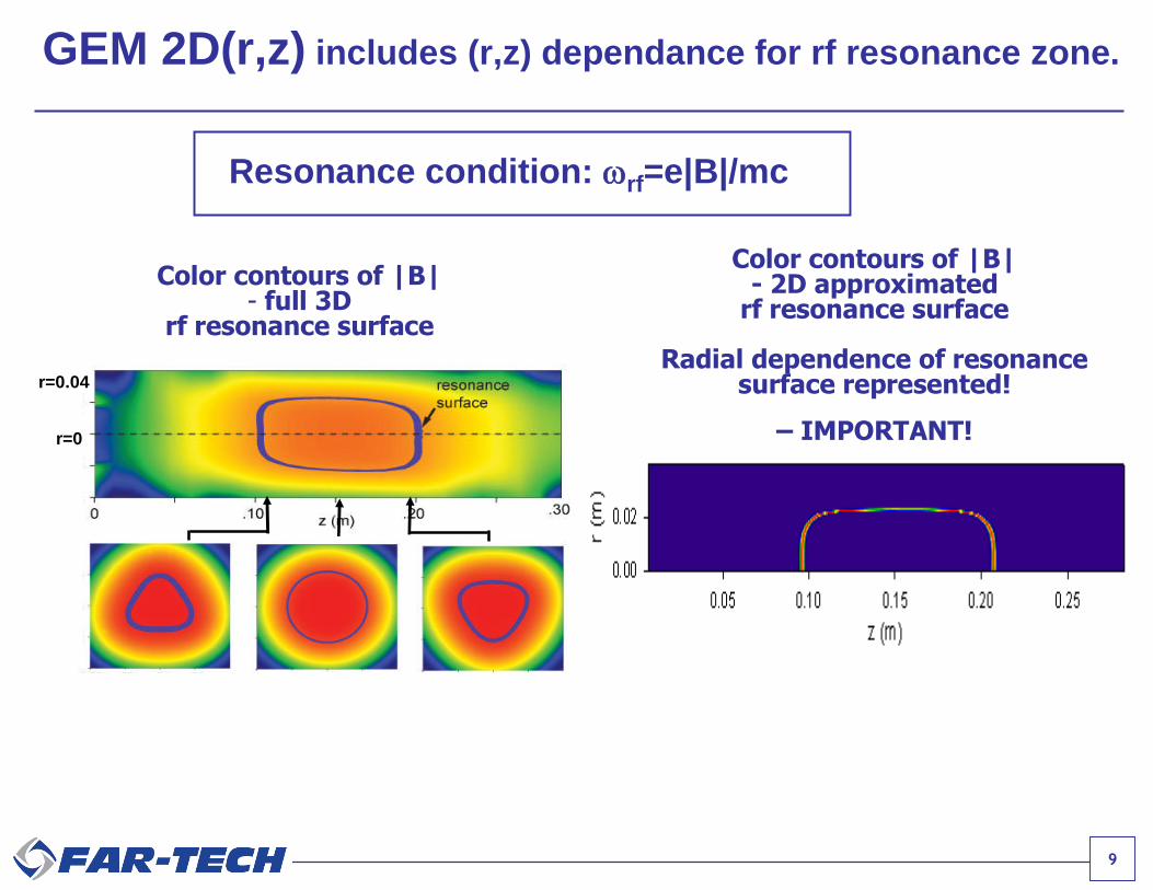
GEM 2D(r,z) includes (r,z) dependance for rf resonance zone.
Resonance condition: rf=e|B|/mc
Color contours of |B|- full 3D
rf resonance surface
Color contours of |B|- 2D approximated
rf resonance surface
Radial dependence of resonancesurface represented!
– IMPORTANT!r=0
r=0.04

10
GEM 2D(r,z) grids
r: radial position of, azimuthally averaged, B-field flux tubesz: axial coordinate
r=0
r= 2.4cmr= 2cm
The r values are on the midplane
Bres
Magneticfieldlines
Z
0.00 0.05 0.10 0.15 0.20 0.25 0.30
R
-0.04
-0.02
0.00
0.02
0.04

11
GEM models dynamics of
(1) Fokker-Plank electrons,
(2) fluid ions, and
(3) particle balanced neutrals.

12
Electron Modeling: Non-Maxwellian electrons are modeled by
Fokker-Planck, Bounce-averaged in the magnetic mirrors.
Mirror trappedelectrons in ECRISare collisionless.
Bz
z
ECR EDF is Non-Maxwellian
13
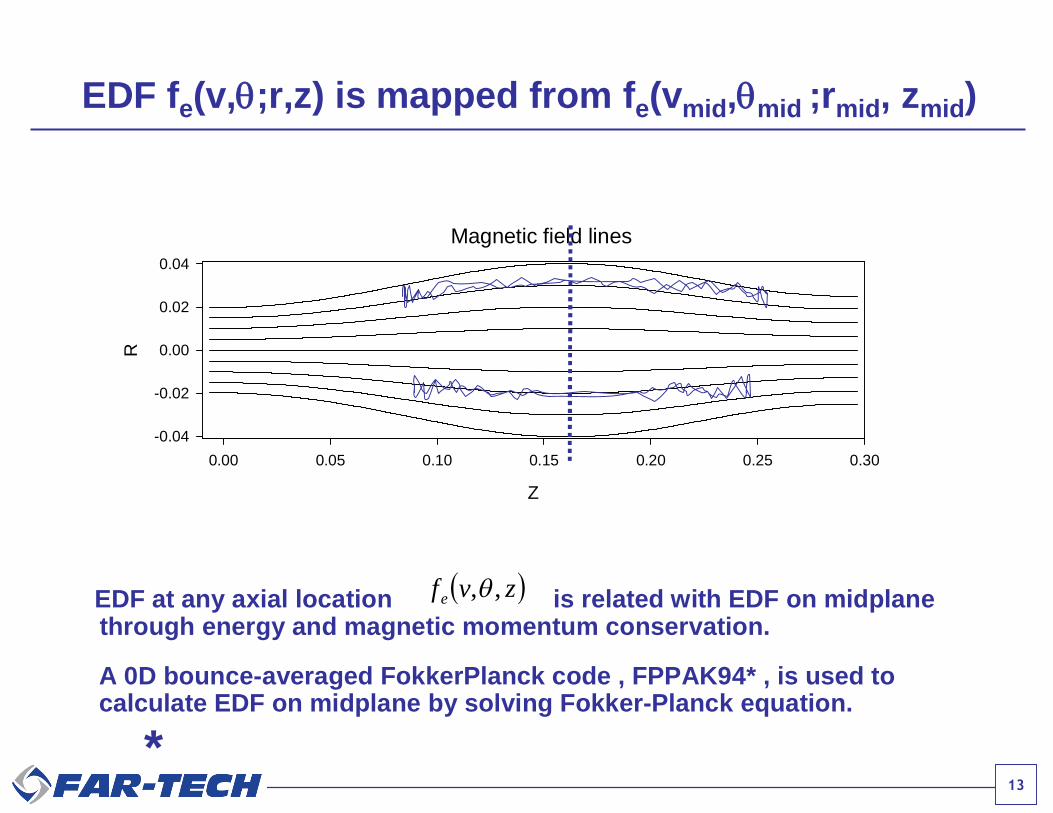
EDF fe(v,;r,z) is mapped from fe(vmid,mid ;rmid, zmid)
Magnetic field lines
Z
0.00 0.05 0.10 0.15 0.20 0.25 0.30
R
-0.04
-0.02
0.00
0.02
0.04
zvf e ,,EDF at any axial location is related with EDF on midplanethrough energy and magnetic momentum conservation.
A 0D bounce-averaged FokkerPlanck code , FPPAK94* , is used tocalculate EDF on midplane by solving Fokker-Planck equation.
*
14
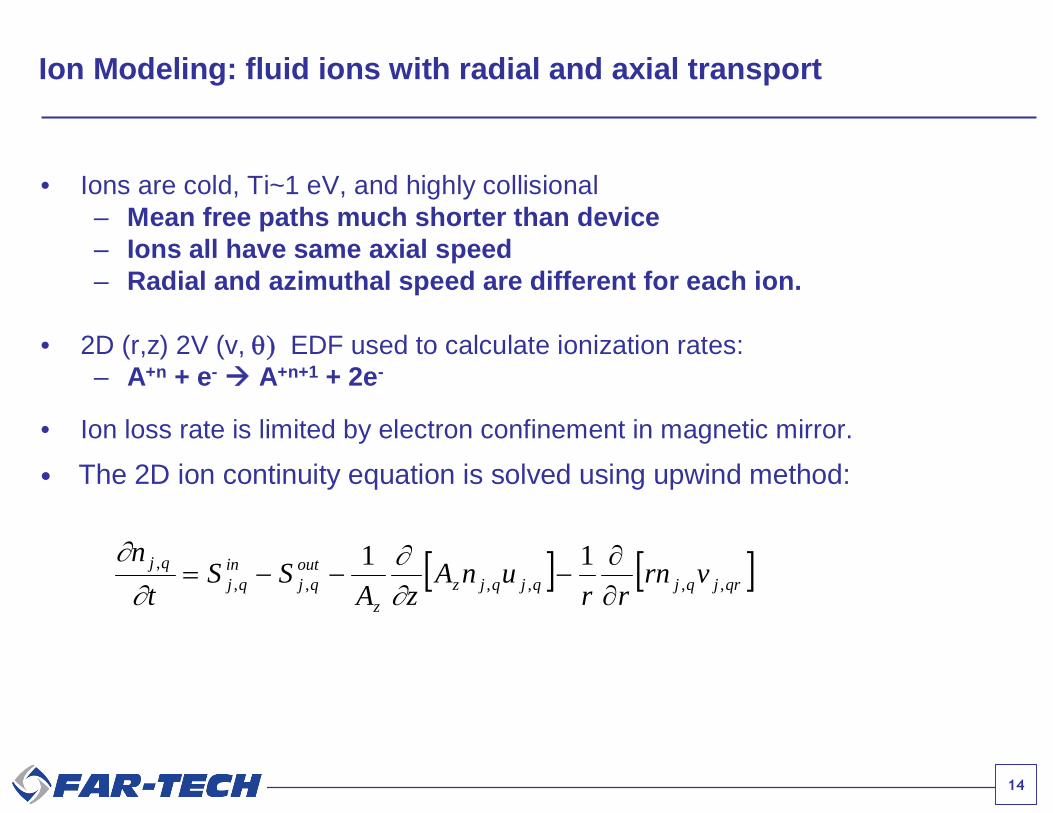
Ion Modeling: fluid ions with radial and axial transport
• The 2D ion continuity equation is solved using upwind method:
qrjqjqjqjzz
outqj
inqj
qj vrnrr
unAzA
SSt
n,,,,,,
, 11
• Ions are cold, Ti~1 eV, and highly collisional– Mean free paths much shorter than device– Ions all have same axial speed– Radial and azimuthal speed are different for each ion.
• 2D (r,z) 2V (v, EDF used to calculate ionization rates:– A+n + e- A+n+1 + 2e-
• Ion loss rate is limited by electron confinement in magnetic mirror.

15
IONS:Cold and highly collisional:Fluid ion model
ELECTRONS:bounce time << collision time:1D bounce-averaged for each flux surfaceFokker-Planck electron code fe(v,; r,z)
NEUTRALS:Unimpeded by magnetic fields:Density profile determined by particle balance
Summary of GEM model

16
Using experimental “knobs” as input, GEM predicts features observed in ECRIS.
Improved agreement with measured CSD by GEM 2D.
ANL ECR-I data
GEM 1D
GEM 2D
Charge State Distribution (CSD)ANL ECR-I Run input parameters
1.2·10-7 torrGas Pressure
oxygenIon Species
323 Wrf Power
10 GHzrf Frequency
4.5 & 3Mirror Ratios
3 cmPlasma Radius(mid plane)
4 cmRadius
29 cmLength
17
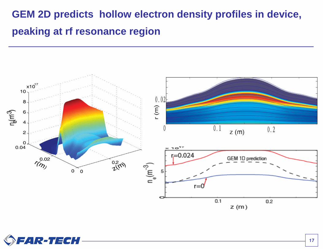
GEM 2D predicts hollow electron density profiles in device,
peaking at rf resonance region

18
GEM 2D predicts hollow electron temperature profiles of
plasma, peaking at rf resonance region

19
GEM 2D predicts hollow CSD of extracted ion sources,
similar to experimental observations.
ANL ECR-I data
r= 0
r= 2cm
r= 2.4cm
J
20
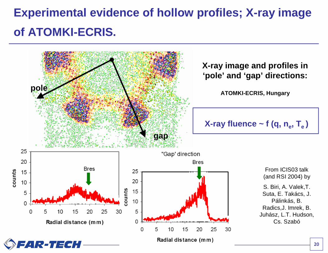
Experimental evidence of hollow profiles; X-ray image
of ATOMKI-ECRIS.
From ICIS03 talk(and RSI 2004) by
S. Biri, A. Valek,T.Suta, E. Takács, J.
Pálinkás, B.Radics,J. Imrek, B.
Juhász, L.T. Hudson,Cs. Szabó
X-ray image and profiles in‘pole’ and ‘gap’ directions:
ATOMKI-ECRIS, Hungary
X-ray fluence ~ f (q, ne, Te )
pole
gap

21
Experimental evidence of hollow profiles; X-ray image
of ATOMKI-ECRIS.
From ICIS03 talk(and RSI 2004) by
S. Biri, A. Valek,T.Suta, E. Takács, J.
Pálinkás, B.Radics,J. Imrek, B.
Juhász, L.T. Hudson,Cs. Szabó
X-ray image and profiles in‘pole’ and ‘gap’ directions:
ATOMKI-ECRIS, Hungary
X-ray fluence ~ f (q, ne, Te )
pole
gap

22
MCBCMonte Carlo Beam Capture Code

23
MCBC tracks injected beams until thermalized by plasma.
Vextract
Grounded tube
ECR Plasma
Groundedelectrode
1+ ion beamn+ ion beam
Microwaves
Magnetic field lines
24
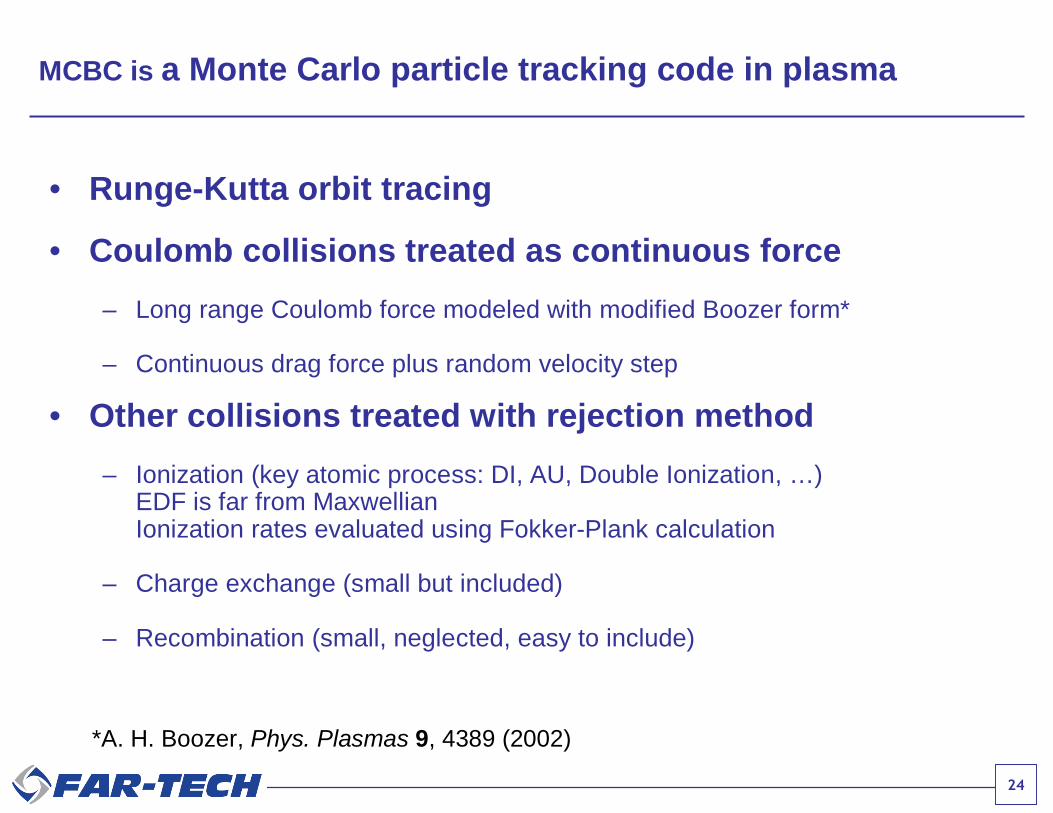
MCBC is a Monte Carlo particle tracking code in plasma
• Runge-Kutta orbit tracing
• Coulomb collisions treated as continuous force
– Long range Coulomb force modeled with modified Boozer form*
– Continuous drag force plus random velocity step
• Other collisions treated with rejection method
– Ionization (key atomic process: DI, AU, Double Ionization, …)EDF is far from MaxwellianIonization rates evaluated using Fokker-Plank calculation
– Charge exchange (small but included)
– Recombination (small, neglected, easy to include)
*A. H. Boozer, Phys. Plasmas 9, 4389 (2002)

25
ne=1.3 e11/cm3
Slowing down of beam ions by plasma
26
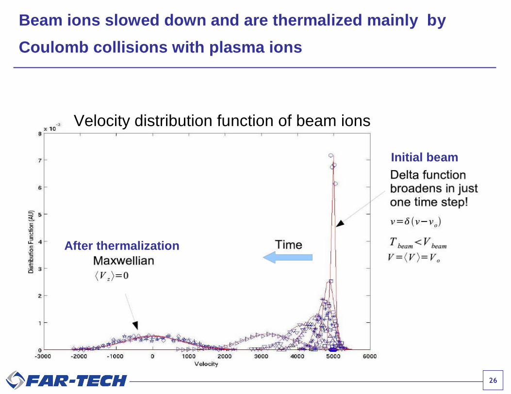
Velocity distribution function of beam ions
Initial beam
After thermalization
Beam ions slowed down and are thermalized mainly by
Coulomb collisions with plasma ions

27
Drag by the background plasma ions is mostly
due to ion-ion Coulomb collisions
• For our parameters,
1mm
TT
1/2
i
e3/2
i
e4
Zvv
ei
ii
Maximum drag due to ion-ion collision occurswhen vi,beam ≈ vth,i-plasma

28
ECR CB Optimization Example
Using MCBC and GEM 1D
Ar1+ ion beam injected intooxygen background plasmausing ANL ECR-I parameters
Goal: Optimize beam energyfor maximum Ar8+ production

29
• When a MCBC beam ion slows tothe ion thermal speed in theplasma, it is considered “captured”
• Distribution of captured ions usedas source profile in GEM
Distribution of captured ions
MCBC
x(m
)Beam ions are either captured, pass through, or lost
Input ionsources for
GEM

30
Beam energy 5eVabove sheath potential 15eV 30eV
Beam capture near the center of the plasma yields better CB
• Reduces backstreaming• Reduces pass through• Increases confinement time

31
<- best
CurrentBeamIonsCapturedofCurrentExtracted
efficiencybreedingCharge
CB efficiency optimization for Ar8+ wrt injected beam energy

32
n e(1
017 m
-3)
0
5
Te
(keV
)
0
5
10
z (m)0.2 0.3 0.4
Pot
entia
l(V
)
0.0
0.3
Plasma density
Avg. Electron Energy
Plasma potential
BzExp.
0.0 0.1 0.2 0.3 0.4 0.5
B(T
)
0.0
0.5
1.0
323 W
750 W
GEM 1D obtained plasma steady states for Prf = 323W and 750W

33
Summary up to this point
• Beam capture near the center for optimum beam extraction
• Higher rf power provide larger central potential dip– Modify beam capture locations (further towards extraction)
– Tends to increases optimum beam energy required
• Higher rf power provide larger electron density, moretemperature (large) – more peaked profiles – may producehigher flux
• Back flow is not small
34
IonExIon Extraction Modeling Code

35
IonEx models beam trajectories in the extraction region
ECR Plasma
1+ ion beamn+ ion beam
Microwaves
Extraction Regionmodeled by IonEx

36
IonEx uses innovative technique to model beam trajectories in
ion extraction region
• Ion beam trajectories depends sensitively on the shape of the “plasma meniscus”• Meniscus is much smaller than extraction optical region• Adaptive techniques are required for accurate modeling in reasonable run time
• IonEx uses innovative Particle-In-Cloud-Of-Points (PICOP) technique– Only points/nodes used in computation– No need to define cells– Easily adapts to complex geometries– Can handle strong anisotropy
• Potentially much faster than standard adaptive mesh techniques– 3D mesh generation can take days for complicated geometry– Point generation is simple– Adaption is easy as no need to redefine cells when points are added or
removed

37
IonEx models ion particles (kinetic) andBoltzmann electrons (fluid)
• Ions– Ions are tracked in self-consistent electrostatic fields and static B- fields– Charge densities are distributed over “neighborhood” of points– Electric fields are calculated from potentials at neighborhood points
• Electrons– Low mass electrons have the Boltzmann distribution
• Point/node locations adapted based on density and potentialgradients to obtain self-consistent, steady state solution,accurately and fast.
ee T
enn
)(exp 0
0

38
Sample IonEx ECRIS extraction region simulation with resolved
plasma sheath
Plasma and electrode parameters:
0650006506320+11202.24 x1017
Φ2(V)Φ1(V)0 (V)Ui (eV)Zimi (amu)Te (eV)n0 (m-3)
z
0
r
Electrode 1 Electrode 2
pla
sma
Short Debye length: cm2μm70 LD
Meniscus
Ion trajectories & equipotentials Point Locations
39
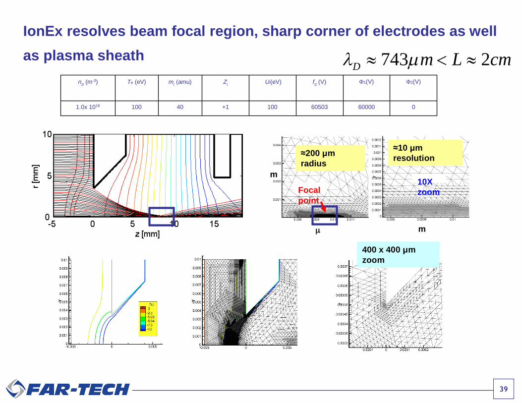
IonEx resolves beam focal region, sharp corner of electrodes as well
as plasma sheath
70 2D m L cm
06000060503100+1401001.0x 1016
Φ2(V)Φ1(V)f0 (V)Ui(eV)Zimi (amu)Te (eV)n0 (m-3)
m
m10Xzoom
743 2D m L cm
≈200 μmradius
≈10 μmresolution
400 x 400 μmzoom
Focalpoint

40
IonEx is benchmarked against IGUN[1]
0 40 80 120 160 200 240 280 320 360 400 440
IGUN-7.031(C)R.Becker - RUN 03/09/07*006, file=ecris2.in
0
40
80
120
160
0 V65000 V
0 40 80 120 160 200 240 280 320 360 400 440
IGUN-7.031(C)R.Becker - RUN 02/21/07*050, file=ecris3.in
0
40
80
120
160
0 V60000 V
[1]: R. Becker and W.B. Hermannsfeldt, “IGUN-A program for the simulation of positive ion extraction includingmagnetic fields,” Rev. Sci. Instrum., 63 (4), 2756 (1992)
← IonEx
94,000 rectangular grid
15,000 nodes 11,670 nodes
← IGUN
IonEx spatial resolution near the focal point was ~10 μm.
IonEx used 11,670 nodes. (cf. over 2M modes required in rectangular grid for thesame resolution.)

41
B-field is implemented in IonEx. IonEx conserves total
energy and the cannonical momentum.
0B
0B
42
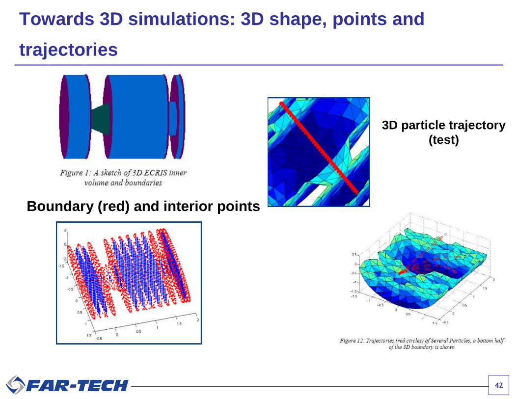
Towards 3D simulations: 3D shape, points and
trajectories
Boundary (red) and interior points
3D particle trajectory(test)

43
IonEx GUI implementation started
44
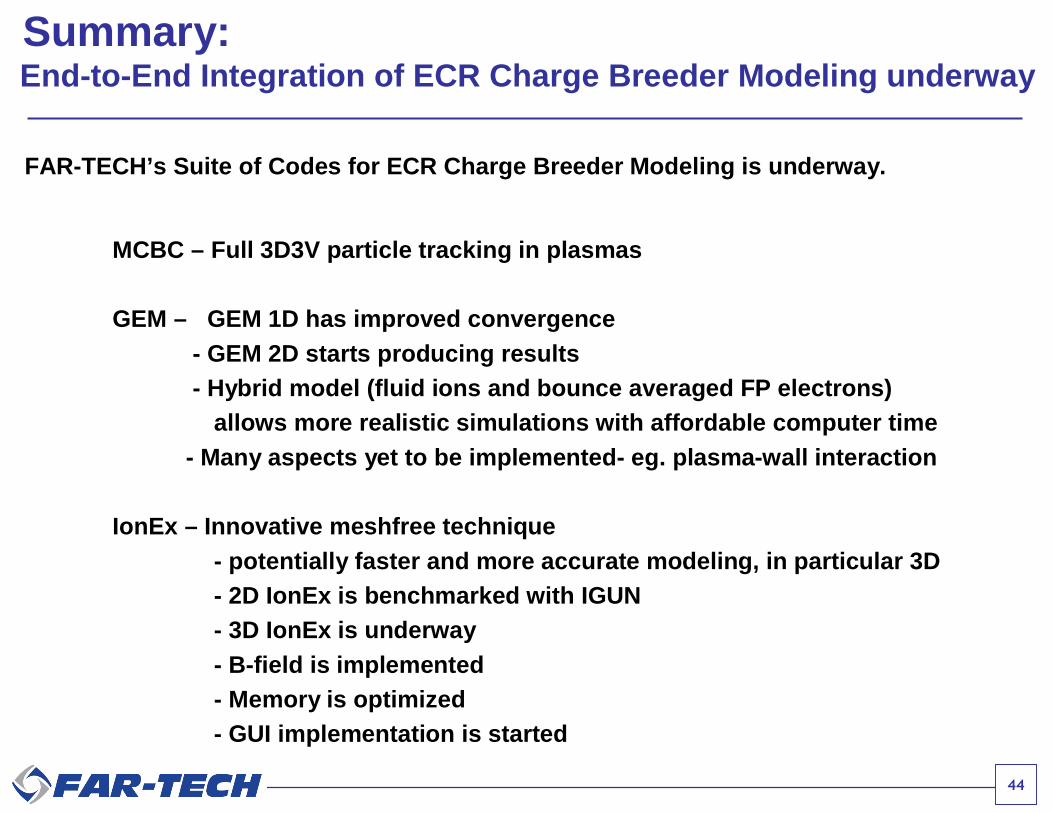
Summary:End-to-End Integration of ECR Charge Breeder Modeling underway
FAR-TECH’s Suite of Codes for ECR Charge Breeder Modeling is underway.
MCBC – Full 3D3V particle tracking in plasmas
GEM – GEM 1D has improved convergence- GEM 2D starts producing results- Hybrid model (fluid ions and bounce averaged FP electrons)
allows more realistic simulations with affordable computer time- Many aspects yet to be implemented- eg. plasma-wall interaction
IonEx – Innovative meshfree technique- potentially faster and more accurate modeling, in particular 3D- 2D IonEx is benchmarked with IGUN- 3D IonEx is underway- B-field is implemented- Memory is optimized- GUI implementation is started
45
Future Work
• Complete 2D extension of GEM
• Complete 3D IonEx
• Validate, validate, and validate!