fans and spares catalogue 2009 master4.indd
TRANSCRIPT

www.fansandspares.co.uk EII
THE OF
Stockist & Distributors of Ventilation products
“Your Job Winning Partner”
22
Roof Twin Fan
34 - 36
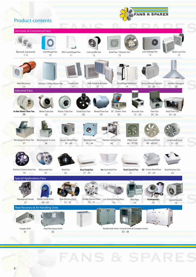
Product contents
Domestic & Commercial Fans
Industrial Fans
Heat Recovery & Air Handling Units
Special Applications Fans
Plastic Fume Fans
68 - 69Flue Dilution Fans
70 - 72Centrif Scrolls
79
Flameproof Axials
67Smoke Extract Fans
73 - 75Hydroponics
78Atex Fans
77Hydroponics
Supply AHU
81Heat Recovery Units
82Residential Units. Central Units & Compact Units.
83 - 88
Bifurcated Fan
55Roof Fan
56Roof Kitchen Fan
65Kitchen Contra Axial Fan
54EC - Green Roof Fans
62 - 64Roof Axial Fan
57 - 59Roof Centrif Fan
61Vertical Axial Fan
60
Rectangular In-Line
38Square Mixed Flow
39 - 40Long Cased Axial
51 - 53Rectangular Duct Fan
37Short Cased Axial
48 - 49/50Multibox Fan
41 - 44Plate Axial
46 - 47/50Kitchen Extract Fan
45
Multi-vent Fan
15
Heat Recovery
16Kitchen / Utility Room Fan
17T-series Fan
17Centrifugal Ventiltion
19Wall, Panel & Window
18
Big book, big brands
7 - 9Axial Fan / Shower Fan
13SELV centrifugal Fan
11Low Voltage Fan
14Centrifugal Fan
10
Metal Tube Fan
26Plastic Tube Fan
27Twin Fan
33 - 34In-line Mixed Flow Fan
25Acoustic Fan
31 - 32Small Duct Fan
28EC - Green Fans
30Mixed Flow Fan
29
Low profile Fan
12
Heat Recovery Centrifugal Ventiltion Central Extract System
20 - 22Kitchen Canopies
23
In-line Mixed Flow Fan
25
Roof Axial Fan Vertical Axial Fan EC - Green Roof Centrif Fan
Car Park & Tunnel Fans
76
33
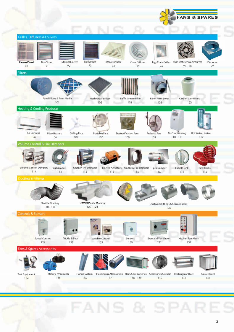
Grilles. Diffusers & Louvres
Filters
Heating & Cooling Products
Volume Control & Fire Dampers
Ducting & Fittings
Controls & Sensors
Fans & Spares Accessories
Motors, AV Mounts
135Flange System
136Flashings & Attenuation
137Heat/Cool Batteries
138 - 139Square Duct
141Rectangular Duct
141Accessories Circular
140
Speed Controls
127Trickle & Boost
128Variable Controls
129Sensors
130Kitchen Fan Alarm
132Demand Ventilation
131
Ductwork Fittings & Consumables
125
Flexible Ducting
118 - 119Domus Plastic Ducting
120 - 124
Iris Dampers
114Smoke/Fire Dampers
115Fire Blocks
116Volume Control Dampers
114Fusible Link
116Electric Actuators
115Tripro Damper
116Smoke & Fire Dampers
116
Ceiling Fans
107Air Curtains
105Air Conditioning
110 - 111Portable Fans
107Pedestal Fan
109Destratification Fans
108
Non Vision
91External Louvre
92Swirl Diffusers & Air Valves
97 - 98Pressed Steel
90Egg Crate Grilles
96Deflection
93Cone Diffuser
954 Way Diffuser
94Pressed Steel Plenums
99
Panel Filters & Filter Media
101Mesh Grease Filter
102Baffle Grease Filter
102Panel Filter Boxes
103Carbon Can-Filters
103
Frico Heaters
106Hot Water Heaters
112
Test Equipment
134
Domus Plastic Ducting

44
The Fans & Spares web site is packed full of useful data from product downloads, technical literature, operating & main-tenance instructions and of course our Web shop with on-line prices ready to purchase 24 hours a day, 7 days a week
To find out more why not visit us at:-
www.fansandspares.co.uk
• Site Visits
• Trade Counters
• Design Advice
• Deliveries Nationwide
• Availability from Warehouse Stocks
55
Fans & Spares Birmingham72 Cheston RoadBirminghamB7 5EJTel : 0121 322 0310Fax : 0121 322 0311 Fans & Spares London Unit1 Midas Business CentreWantz RoadDagenhamRM10 8PSTel : 0208 595 5226Fax : 0208 593 4257 Fans & Spares Scotland Unit 9 & 10 Port Dundas Trading EstateNorth Canal Bank StreetGlasgowG4 9XPTel : 0141 333 0202Fax : 0141 331 1672 Fans & Spares South East Unit 10 Northpoint Business EstEnterprise CloseMedway City EstateRochesterME2 4LXTel : 01634 295 724Fax : 01634 294 723
Fans & Spares are pleased to present the Bigger Book, which is a modest attempt to list some of the wide choice of ventilation equipment available from our nationwide network of branches. We hope you fi nd this a most comprehensive catalogue, packed full of information, with great choice, as you would expect from a leading ventilation distributor. At Fans & Spares we have a very simple mission statement :-
“We make it Easy”• Express-air - our own brand of job winning products• Availability of stocks, from our network of branches• Service & technical advice you can rely on• Your choice of products & manufacturers
If you can’t fi nd what you are looking for or you need some technical advice, then just ask. When it comes to Ventilation there is only one company you need to call.
From your job winning partner.
Neil RapleyManaging Director
Branch LocationsFans & Spares Leeds 10 Low Mills RoadLeedsLS12 4UYTel : 0113 279 0501Fax : 0113 231 0969 Fans & Spares Leicester Unit 10The Beaver CentreFreemens CommonLeicesterLE2 7TDTel : 0116 254 9898Fax : 0116 247 0590
Fans & Spares ManchesterUnit 1 Dakota SouthDakota AvenueSalfordManchesterM50 2PUTel : 0161 873 7212Fax : 0161 848 7293
Fans & Spares NottinghamUnit 25 Whitemoor CourtOff Nuthall RoadNottinghamNG8 5BYTel : 0115 929 4104Fax : 0115 929 2710
Fans & Spares SouthernRomsey Industrial EstateGreatbridge RoadRomseySO51 0HRTel : 01794 830399Fax : 01794 830336
Fans & Spares StokeUnit 2 Rosevale RoadParkhouse Ind Est WestNewcastle-under-LymeStaffordshireST5 7EFTel : 01782 579076Fax : 01782 563592
Fans & Spares High WycombeUnit 88 Cressex Enterprise CentreLincoln RoadHigh WycombeBuckinghamshireHP12 3RLTel : 01494 614566Fax : 01494 614665
Fans & Spares North EastThe Axis BuildingMaingateTeam Valley Trading EstateGatesheadNE11 0NQTel : 0191 4047037Fax : 0191 4046913
5
6
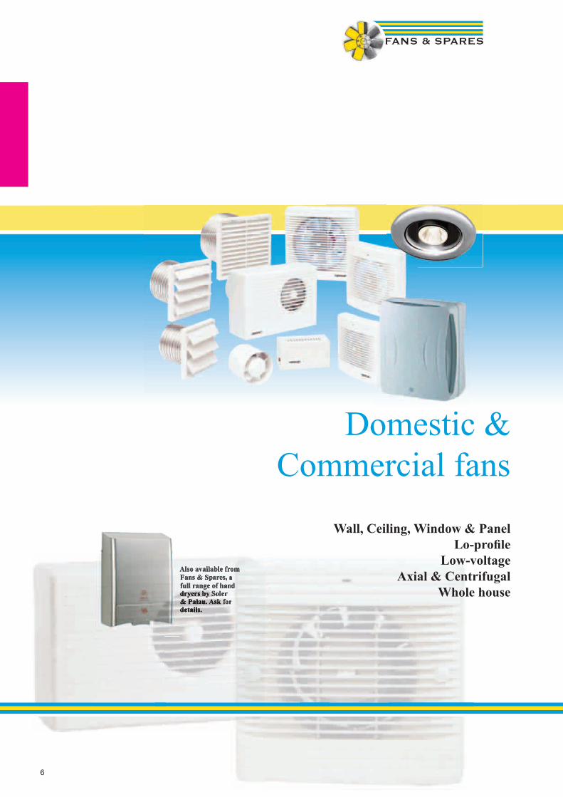
Domestic & Commercial fans
Wall, Ceiling, Window & Panel
Lo-profi leLow-voltage
Axial & CentrifugalWhole house
Also available from Fans & Spares, a full range of hand dryers by Soler & Palau. Ask for details.
Also available from Also available from Fans & Spares, a Fans & Spares, a full range of hand full range of hand dryers by Soler & Palau. Ask for & Palau. Ask for details.

7
Big Book, Big Brands
Xpelair Featured Product: PX RangeIntroducing a new addition to the Xpelair commercial range. The PX range introduces even greater flexibility into the design of commercial and largerdomestic ventilation systems. Based on the proven WX range, PX fans are perfect for ceiling and panel applications in kitchens, restaurants, pubs,offices, schools, shops and kiosks. They can be installed at any angle in ceilings, voids and wall panels of any thickness. The ceiling hugging, low profile white fascia is styled to blend into any ceiling type, whether smooth, tiled or textured. For safety, a finger guard is integrated into the ultra slim high gloss ABS fascia. An integral spigot allows the attachment of flexible ducting, such asXFlex. Installation in ceilings and wall panels is rapid thanks to the concealed fixing points provided. Both the PX9 &PX12 are reversible making them idealfor ducted input systems in the hospitality industry. On PX9 & PX12 units a positive plug and socket assembly provides a means of isolationfor service access without the safety risk of accidental disconnection. PX9 & PX12 models feature totally enclosed external rotor motorsproviding constant volume outputs, even in gusty external conditions. Pre-balanced sickle bladed impellers eliminate’ fan judder’ and ensure quiettrouble free operation. Sealed for life maintenance free bearings ensure suitability for running at any angle. Running costs are impressively low,and when not in use the silent electro-thermal shutter cassette closes silently against backdraughts. And cleaning has never been easier. The housing, shutter cassette and impeller are all removed in seconds.
Xpelair CentrX Range Xpelair CMF Range Xpelair PX Range Xpelair SL Range
Greenwood Airvac Featured Product: Unity Range
SAP Appendix Q eligible which will help reduce DER’s (dwelling emission rates) in SAP. Also suitable to help achieve level 3 and above of the code for sustain-able Homes.The one and only...decentralised MeV system with BBA certification available in the domestic market. Simple and easy to apply in existing designs with indi-vidual room fans.Just 2 watts....significantly low energy consumption makes Unity an energy savvy choice.All for one and one for all....one fan, any room, all installations, simply the only fan you need to design in and specify.Just one window vent....no need for loads of window vents now required with intermittent fans – just one per habitable room (2,500mm2 equivalent area).Shhhh…silent ventilation with no risk of noise and complete comfort for homeowners.It does what it says on the box....intelligent design features constant volume sensor which alters speed with any pressure changes – always guaranteeing building ventilation requirements.Hide and seek....stylish and discreet front fascia blends in with room décor.UK’s first carbon neutral fan....Just another one of our commitments to reducing carbon emissions.From inside to out....extremely low energy ec motor, patented technology, H&V domestic product of the year finalist 2007.
Greenwood Unity Range Greenwood AXSK RangeGreenwood Eco RangeGreenwood SF90 Range
New highly efficient product offering low power consumption thanks to the brushless motor and specially designed electronic control system. For the ventilation of medium-sized rooms in commercial premises plus bathrooms/showers and toilets in domestic situations. 4 models with or without timer. Surface mounting and built-in versions available. Backdraught shutter incorporated to avoid air back-flow when the unit is turned off. Timer models adjustable between 3 and 20 minutes. Reduced sound levels with superior certified performances on ducted applications. Two Speeds. All models feature two speed operation, including timer equipped models. Vort Quadro fans guarantee a low environmental impact. Recyclable materials have been used and the “Design for Disassembly” technique has been followed (2002/96/EC - WEEE).
Vortice Featured Product: Quadro ES RangeVortice Quadro ES RangeVortice Tiracamino RangeVortice Volt Press RangeVortice Punto Filo Range

8
Big Book, Big Brands
The choice of three fans in the iCON range means you can fit the perfect size of fan to suit the room and the application. The iCON 15 axial fan is sleek and slim. The iCON 30 and iCON 60 mixed centrifugal/axial fan flow technology makes them not only highly compact and efficient, but also extremely quiet in operation, and suitable for use with ducting. All fans are supplied with three years no quibble replacement product guarantee
iCON 15 is ideal for toilets, en-suites, shower rooms and bathrooms, recessed into the wall or ceiling, it is stylish and unobtrusive, even in the smallest space. iCON 30 is quiet, powerful and designed for recessed or surface mounting in walls or ceilings in larger toilets, bathrooms and utility rooms. iCON 60 is the largest fan in the range, suitable for recessed or surface mounting in walls or ceilings and is highly efficient in domestic kitchens and residents’ loungesiCON15S is ideal for toilets, en-suites, shower rooms and bathrooms. Recessed into the wall or ceiling, it is stylish and unobtrusive, even in the smallest space. Supplied with a 12V DC transformer it is extra safe too.iCON30S is ideal for toilets, en-suites, shower rooms, utility rooms and bathrooms. Recessed or surface mounted into the wall or ceiling, it is stylish andunobtrusive. Operating from 12V DC supply it is extra safe too.iCON fans complement modern day living by harmonising with virtually any interior design. Neat, unobtrusive and stylish, iCON fans provide quiet and reliable ventilation while blending into the background. Available from stock in Anthracite, Gold, Silver and Glacier white matt wipe clean finish, they add colour and co-ordination to your toilet, bathroom and kitchen - and at surprisingly low cost. iCON 15S and iCON 30S are energy saving and extra save - they comply with the latest IEE wiring regulations for installation in wet zones and are supplied with a 12V DC transformer.
ModulesBasic-Fan operates by remote switch (not supplied). No module requiredPCS-Pull Cord-On/Off by integral pull cordPCTS-Pull Cord with -Timer-adjustable 1 to 45 minutes.HTS-Humidity-adjustable 40% to 90% RH, adjustable timer and pull cord boostPRTS-Infrared Timer- Passive Infrared activation with adjustable run-on timerPRHTS-Infrared Humidity Timer- Passive infrared activation with adjustable humidity/adjustable timer
The QuietAir range from Airflow sets new standards for powerful, yet highly efficient ventilation in the home, and with a sound level of just 25 dB(A) you will hardly notice it is running.Quietair combines contemporary design with ultra low noise levels and outstanding energy efficiency.Quietair sets new standards for the reliable, low cost ventilation of toilets, en-suites and bathrooms; and at just 25dB(A) you will hardly hear the fan running, even at night!Low Energy, High Tech!• High efficiency impeller delivers up to 60m3/hr through 12m of rigid ducting, including 90° bends• Integral flow straightener and back draught flap• Low specific fan power for SAP assessments• Clip-on cover for ease of cleaning• Innovative room refresh option (interval timer) programmable for automatic long term routine ventilation• Complies with latest Building Regulations Approved Document F
Dimensions & Performance
QUIETAIR
8
The choice of three fans in the iCON range means you can fit the perfect size of fan to suit the room and the application. The choice of three fans in the iCON range means you can fit the perfect size of fan to suit the room and the application. The iCON 15 axial fan is sleek and slim. The iCON 30 and iCON 60 mixed centrifugal/axial fan flow technology makes The iCON 15 axial fan is sleek and slim. The iCON 30 and iCON 60 mixed centrifugal/axial fan flow technology makes them not only highly compact and efficient, but also extremely quiet in operation, and suitable for use with ducting. All fans are supplied with three years no quibble replacement product guarantee
iCON 15 is ideal for toilets, en-suites, shower rooms and bathrooms, recessed into the wall or ceiling, it is stylish and unobtrusive, even in the smallest space. iCON 30 is quiet, powerful and designed for recessed or surface mounting in walls or ceilings in larger toilets, bathrooms and utility rooms. iCON 60 is the largest fan in the range, suitable for recessed or surface mounting in walls or ceilings and is highly efficient in domestic kitchens and residents’ loungesiCON15S is ideal for toilets, en-suites, shower rooms and bathrooms. Recessed into the wall or ceiling, it is stylish and unobtrusive, even in the smallest space. Supplied with a 12V DC transformer it is extra safe too.iCON30S is ideal for toilets, en-suites, shower rooms, utility rooms and bathrooms. Recessed or surface mounted into the wall or ceiling, it is stylish andunobtrusive. Operating from 12V DC supply it is extra safe too.iCON fans complement modern day living by harmonising with virtually any interior design. Neat, unobtrusive and stylish, iCON fans provide quiet and reliable ventilation while blending into the background. Available from stock in Anthracite, Gold, Silver and Glacier white matt wipe clean finish, they add colour and co-ordination to your toilet, bathroom and kitchen - and at surprisingly low cost. iCON 15S and iCON 30S are energy saving and extra save - they comply with the latest IEE wiring regulations for installation in wet zones and are supplied with a 12V DC transformer.
ModulesBasic-Fan operates by remote switch (not supplied). No module requiredPCS-Pull Cord-On/Off by integral pull cordPCTS-Pull Cord with -Timer-adjustable 1 to 45 minutes.HTS-Humidity-adjustable 40% to 90% RH, adjustable timer and pull cord boostPRTS-Infrared Timer- Passive Infrared activation with adjustable run-on timerPRHTS-Infrared Humidity Timer- Passive infrared activation with adjustable humidity/adjustable timer
The QuietAir range from Airflow sets new standards for powerful, yet highly efficient ventilation in the home, and with a sound level of just 25 dB(A) you will hardly notice it is running.Quietair combines contemporary design with ultra low noise levels and outstanding energy efficiency.Quietair sets new standards for the reliable, low cost ventilation of toilets, en-suites and bathrooms; and at just 25dB(A) you will hardly hear the fan running, even at night!Low Energy, High Tech!• High efficiency impeller delivers up to 60m3/hr through 12m of rigid ducting, including 90° bends• Integral flow straightener and back draught flap• Low specific fan power for SAP assessments• Clip-on cover for ease of cleaning• Innovative room refresh option (interval timer) programmable for automatic long term routine ventilation• Complies with latest Building Regulations Approved Document F
Dimensions & Performance
QUIETAIR

9
Domestic Fansby Elta
The SA Axial Range is a stylish range of axial flow fans which provides powerful extract of air through windows, walls, ceilings and panels for a variety of domestic and commercial applications.
• 3 standard sizes from 100mm to 150mm.
• Air volume flow rates of up to 0.088 m³/s (317 m³/hr).
• Static pressures of up to 80 Pa.
• Axial impeller design for larger volumes.
• IPX4 – Splash proof.
• Shock proof, heat resistant plastic.
• Suitable for operating temperatures up to 40°C.
• Motors are double insulated with built-in thermal overload protection.
• CE Marked and BEAB approved.
• Sealed for life ball bearings to operate at any angle.
• Timer models adjustable from 3-15 minutes.
• Lower noise levels.The SA LV Axial Range is a stylish range of axial flow fans which have been specifically developed to ensure complete safety in the appropriately regulated “Safety Zones”, providing powerful extract of air through windows, walls, ceilings and panels for a variety of domestic and commercial applications.
Air volume flow rates of up to 0.088 m³/s (317 m³/hr).
Suitable for operating temperatures up to 40°C.
The SC Range is a range of centrifugal flow fans which offer excellent pressure developmentcharacteristics, designed specifically for use with rigid or flexible ductwork for a wide variety of residential and commercial applications.
• 1 standard size 100mm.
• Air volume flow rates of up to 0.03 m³/sec (108m³/h).
• Static pressures of up to 120 Pa.
• Greater pressure capability than axial fans.
• IPX4 – Splash proof.
• Shock proof, heat resistant plastic.
• Suitable for operating temperatures up to 40°C.
• Motors are double insulated with built-in thermal overload protection.
• CE Marked and BEAB approved.
• Sealed for life ball bearings to operate at any angle.
• Timer models adjustable from 3-15 minutes.
• Anti–vibration gasket between fan casing and wall for quiet operation.
• Supplied with back draught shutter and inlet cone for improved performance.The SC LV Centrifugal Range is a range of centrifugal flow fans which have been specificallydeveloped to ensure complete safety in the appropriately regulated “Safety Zones”, offering excellent pressure development characteristics, designed specifically for use with rigid or flexible ductwork for a wide variety of residential and commercial applications.
The SE “Executive” Axial Range is a stylish range of slim profile axial flow fans which provides powerful extract of air through windows, walls, ceilings and panels for a variety of domestic and commercial applications.
• 3 standard sizes from 100mm to 150mm.
• Air volume flow rates of up to 0.088 m³/s (317 m³/hr).
• Static pressures of up to 80 Pa.
• Axial impeller design for larger volumes.
• IPX4 – Splash proof.
• Shock proof, heat resistant plastic.
• Suitable for operating temperatures up to 40°C.
• Motors are double insulated with built-in thermal overload protection.
• CE Marked and BEAB approved.
• Sealed for life ball bearings to operate at any angle.
• Timer models adjustable from 3-15 minutes.
• Front plate fascia protrudes between 8mm and 15mm dependant on model, provid-ing one of the slimmest profile fans on the market
The SE LV “Executive” Axial Range is a stylish range of slim profile axial flow fans which have beenspecifically developed to ensure complete safety in the appropriately regulated “Safety Zones”,providing powerful extract of air through windows, walls, ceilings and panels for a variety of domestic and commercial applications.
Motors are double insulated with built-in thermal overload protection.
The SCE “Executive” Centrifugal Range is a stylish range of slim profile centrifugal flow fans which offer excellent pressure development characteristics, designed specifically for use with rigid or flexible ductwork for a wide variety of residential and commercial applications.
• 1 standard size 100mm.
• Air volume flow rates of up to 0.036 m³/s (130 m³/hr).
• Static pressures of up to 127 Pa.
• Greater pressure capability than axial fans.
• IPX4 – Splash proof.
• Shock proof, heat resistant plastic.
• Suitable for operating temperatures up to 40°C.
• Motors are double insulated with built-in thermal overload protection.
• CE Marked and BEAB approved.
• Sealed for life ball bearings to operate at any angle.
• Timer models adjustable from 3-15 minutes.
• Front plate fascia protrudes 19mm, providing one of the slimmest profile fans on the market.
• Supplied with backdraught shutter.
The SCE LV “Executive” Centrifugal Range is a range of slim profile centrifugal flow fans which have been specifically developed to ensure complete safety in the appropriately regulated “Safety Zones”, offering excellent pressure development characteristics, de-signed specifically for use with rigid or flexible ductwork for a wide variety of residential and commercial applications.
SAX Commercial Wall / Window FanThe SAX is a stylish, high performance range of axial flow fans which provides powerful extract of air through windows, walls, ceilings and panels for a variety of domestic and commercial applications
• Axial impeller design for larger volumes.
• Two standard sizes, 9” and 12”
• Automatic and reversible models.
• Air volume flow rates of up to 0.528 m³/s (1900 m³/hr).
• Static pressures of up to 80 Pa.
• Shock proof, heat resistant plastic.
• Motors are double insulated with built in thermal overload protec-tion.
• Sealed for life ball bearings to operate at any angle.
• Energy efficient with low power absorption.
DetailsProduct Code Description Voltage m³/hr /
l/secReversible Speed
Control option
Speed Control standard
SAX23/9A Basic unit, fan only 230 824 / 229 No Yes
SAX23/9A Run on timer unit 230 824 / 229 Yes Yes
SAX23/9A Includes telescopic steel wall liner
230 824 / 229 Yes Yes
SAX23/9A Basic unit, fan only 230 1900 / 528 No Yes
SAX23/9A Run on timer unit 230 824 / 229 Yes Yes
SAX23/9A Includes telescopic steel wall liner
230 824 / 229 Yes Yes
Mounting arrangements: All fans can be Ceiling, Wall, Window or Fan only.
10
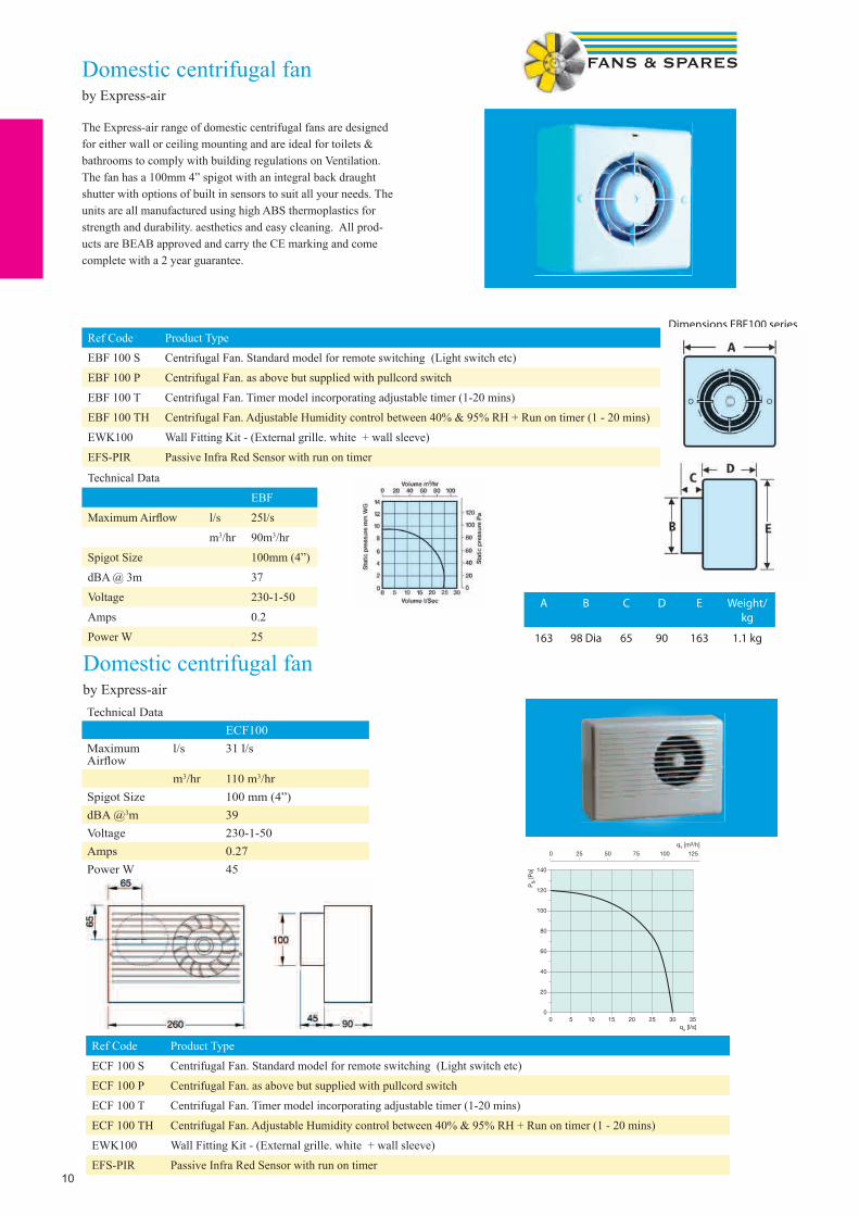
Domestic centrifugal fanby Express-air
The Express-air range of domestic centrifugal fans are designed for either wall or ceiling mounting and are ideal for toilets & bathrooms to comply with building regulations on Ventilation. The fan has a 100mm 4” spigot with an integral back draught shutter with options of built in sensors to suit all your needs. The units are all manufactured using high ABS thermoplastics for strength and durability. aesthetics and easy cleaning. All prod-ucts are BEAB approved and carry the CE marking and come complete with a 2 year guarantee.
Technical Data
EBF
Maximum Airfl ow l/s 25l/s
m3/hr 90m3/hr
Spigot Size 100mm (4”)
dBA @ 3m 37
Voltage 230-1-50
Amps 0.2
Power W 25
Ref Code Product Type
EBF 100 S Centrifugal Fan. Standard model for remote switching (Light switch etc)
EBF 100 P Centrifugal Fan. as above but supplied with pullcord switch
EBF 100 T Centrifugal Fan. Timer model incorporating adjustable timer (1-20 mins)
EBF 100 TH Centrifugal Fan. Adjustable Humidity control between 40% & 95% RH + Run on timer (1 - 20 mins)
EWK100 Wall Fitting Kit - (External grille. white + wall sleeve)
EFS-PIR Passive Infra Red Sensor with run on timer
A B C D E Weight/kg
163 98 Dia 65 90 163 1.1 kg
Dimensions EBF100 series
Domestic centrifugal fanby Express-airTechnical Data
ECF100Maximum Airfl ow
l/s 31 l/s
m3/hr 110 m3/hrSpigot Size 100 mm (4”)dBA @3m 39Voltage 230-1-50Amps 0.27Power W 45
Ref Code Product Type
ECF 100 S Centrifugal Fan. Standard model for remote switching (Light switch etc)
ECF 100 P Centrifugal Fan. as above but supplied with pullcord switch
ECF 100 T Centrifugal Fan. Timer model incorporating adjustable timer (1-20 mins)
ECF 100 TH Centrifugal Fan. Adjustable Humidity control between 40% & 95% RH + Run on timer (1 - 20 mins)
EWK100 Wall Fitting Kit - (External grille. white + wall sleeve)
EFS-PIR Passive Infra Red Sensor with run on timer

11
Premier UltraDCCentrifugal safety extra low voltage fan by Xpelair
Technical Data
Reference Number 92288AWIntegral pullcord boost override 15 l/s
Adjustable overrun timer 30 sec - 20 mins
Quick Visit delayed On 2 mins
Active response humidistat 70 - 90% RH. Factory set at 70% RH
Selectable installed performances 6, 8, 13, 15 l/s
Sound pressure level (dB(A)@3m) - 6l/s 29.6
Electrical power rating- 6l/s 3.5W
IP rating IPX5
Weight 4.25kg
Transformer Located outside of spray area Zone 3
The Xpelair Premier Selv with UltraDC technology, safe, energy efficient and long lasting.The Premier is designed with installer selectable settings to satisfy Document F1 installed performances for continuous ventilation in bathrooms and sanitary accommodation; continuous extract in kitchens, utility rooms, bathrooms and sanitary accommodation, all from one fan with whisper quiet operation.Premier offers centrifugal performance with an UltraDC motor. This ensures a constant pressure development and lower energy use than many axial ec fans and requires no filter.Versatile standard built-in options allow the installer to select any combination of advanced features: active response humidity control, adjustable overrun timer, ‘Quick visit’ delayed start and pullcord BOOST override.The unit can be surface or recess mounted at any angle.For complete peace of mind Premier LVCF20TDC is IPX5 Safety Extra Low Voltage rated for installation in splash zone 1 and zones 2 / 3 of a bath or shower. Premier features UltraDC offering an 80% reduction in energy use, a choice of installed performances and longer life, typically up to five times longer than a conventional AC motor.
• Selv UltraDC Centrifugal Wall fan with CF, condensation control,and overrun timer.• Application: Intermittent ventilation in Toilets & Bathrooms.• Continuous extract in kitchens, utility rooms, bathrooms or toilets.• Control options: Pullcord override. Quick visit 2min delay.• Adjustable timer overrun.• Adjustable humidistat.• Surface or recess mounting• Auto run status light• Pullcord boost override with status light
Premier Ultra LVCF20T
Hole Diameter 115mmDuct Size 100mm
Also Available shower fan & light systems
12
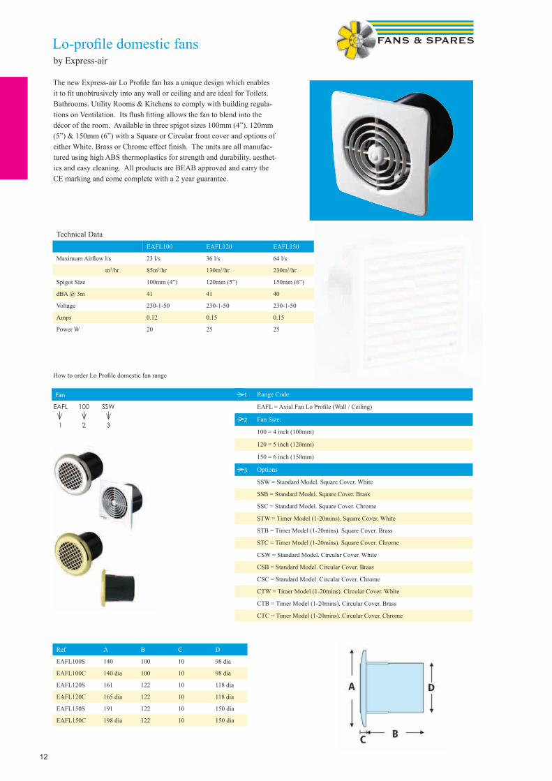
Lo-profi le domestic fansby Express-air
The new Express-air Lo Profi le fan has a unique design which enables it to fi t unobtrusively into any wall or ceiling and are ideal for Toilets. Bathrooms. Utility Rooms & Kitchens to comply with building regula-tions on Ventilation. Its fl ush fi tting allows the fan to blend into the décor of the room. Available in three spigot sizes 100mm (4”). 120mm (5”) & 150mm (6”) with a Square or Circular front cover and options of either White. Brass or Chrome effect fi nish. The units are all manufac-tured using high ABS thermoplastics for strength and durability. aesthet-ics and easy cleaning. All products are BEAB approved and carry the CE marking and come complete with a 2 year guarantee.
1 Range Code:
EAFL = Axial Fan Lo Profi le (Wall / Ceiling)
2 Fan Size:
100 = 4 inch (100mm)
120 = 5 inch (120mm)
150 = 6 inch (150mm)
3 Options
SSW = Standard Model. Square Cover. White
SSB = Standard Model. Square Cover. Brass
SSC = Standard Model. Square Cover. Chrome
STW = Timer Model (1-20mins). Square Cover. White
STB = Timer Model (1-20mins). Square Cover. Brass
STC = Timer Model (1-20mins). Square Cover. Chrome
CSW = Standard Model. Circular Cover. White
CSB = Standard Model. Circular Cover. Brass
CSC = Standard Model. Circular Cover. Chrome
CTW = Timer Model (1-20mins). Circular Cover. White
CTB = Timer Model (1-20mins). Circular Cover. Brass
CTC = Timer Model (1-20mins). Circular Cover. Chrome
Technical DataEAFL100 EAFL120 EAFL150
Maximum Airfl ow l/s 23 l/s 36 l/s 64 l/s
m3/hr 85m3/hr 130m3/hr 230m3/hr
Spigot Size 100mm (4”) 120mm (5”) 150mm (6”)
dBA @ 3m 41 41 40
Voltage 230-1-50 230-1-50 230-1-50
Amps 0.12 0.15 0.15
Power W 20 25 25
How to order Lo Profi le domestic fan range
Fan
Ref A B C D
EAFL100S 140 100 10 98 dia
EAFL100C 140 dia 100 10 98 dia
EAFL120S 161 122 10 118 dia
EAFL120C 165 dia 122 10 118 dia
EAFL150S 191 122 10 150 dia
EAFL150C 198 dia 122 10 150 dia
EAFL 100 SSW
1 2 3
13
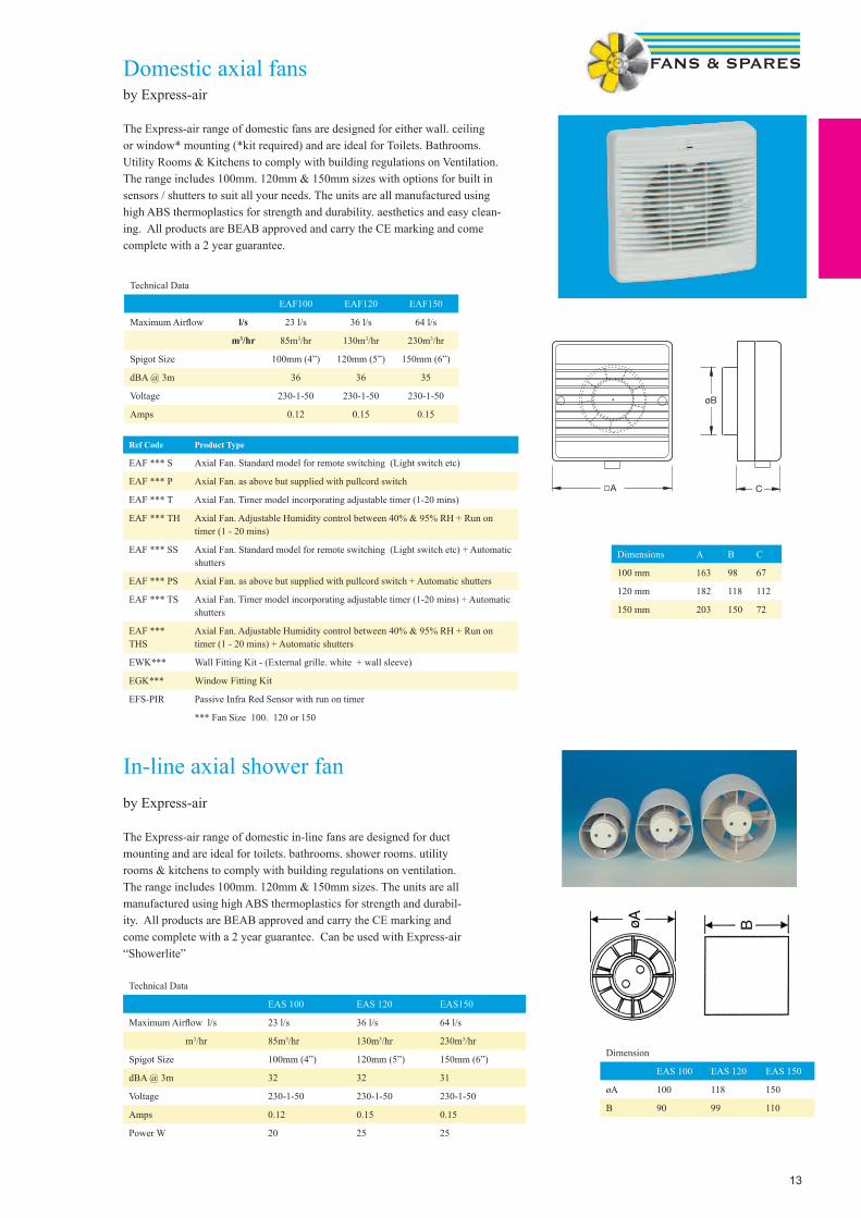
Domestic axial fansby Express-air
The Express-air range of domestic fans are designed for either wall. ceiling or window* mounting (*kit required) and are ideal for Toilets. Bathrooms. Utility Rooms & Kitchens to comply with building regulations on Ventilation. The range includes 100mm. 120mm & 150mm sizes with options for built in sensors / shutters to suit all your needs. The units are all manufactured using high ABS thermoplastics for strength and durability. aesthetics and easy clean-ing. All products are BEAB approved and carry the CE marking and come complete with a 2 year guarantee.
Technical Data
EAF100 EAF120 EAF150
Maximum Airflow l/s 23 l/s 36 l/s 64 l/s
m3/hr 85m3/hr 130m3/hr 230m3/hr
Spigot Size 100mm (4”) 120mm (5”) 150mm (6”)
dBA @ 3m 36 36 35
Voltage 230-1-50 230-1-50 230-1-50
Amps 0.12 0.15 0.15
Ref Code Product Type
EAF *** S Axial Fan. Standard model for remote switching (Light switch etc)
EAF *** P Axial Fan. as above but supplied with pullcord switch
EAF *** T Axial Fan. Timer model incorporating adjustable timer (1-20 mins)
EAF *** TH Axial Fan. Adjustable Humidity control between 40% & 95% RH + Run on timer (1 - 20 mins)
EAF *** SS Axial Fan. Standard model for remote switching (Light switch etc) + Automatic shutters
EAF *** PS Axial Fan. as above but supplied with pullcord switch + Automatic shutters
EAF *** TS Axial Fan. Timer model incorporating adjustable timer (1-20 mins) + Automatic shutters
EAF *** THS
Axial Fan. Adjustable Humidity control between 40% & 95% RH + Run on timer (1 - 20 mins) + Automatic shutters
EWK*** Wall Fitting Kit - (External grille. white + wall sleeve)
EGK*** Window Fitting Kit
EFS-PIR Passive Infra Red Sensor with run on timer
*** Fan Size 100. 120 or 150
Dimensions A B C
100 mm 163 98 67
120 mm 182 118 112
150 mm 203 150 72
In-line axial shower fanby Express-air
The Express-air range of domestic in-line fans are designed for duct mounting and are ideal for toilets. bathrooms. shower rooms. utility rooms & kitchens to comply with building regulations on ventilation. The range includes 100mm. 120mm & 150mm sizes. The units are all manufactured using high ABS thermoplastics for strength and durabil-ity. All products are BEAB approved and carry the CE marking and come complete with a 2 year guarantee. Can be used with Express-air “Showerlite”
Technical Data
EAS 100 EAS 120 EAS150
Maximum Airflow l/s 23 l/s 36 l/s 64 l/s
m3/hr 85m3/hr 130m3/hr 230m3/hr
Spigot Size 100mm (4”) 120mm (5”) 150mm (6”)
dBA @ 3m 32 32 31
Voltage 230-1-50 230-1-50 230-1-50
Amps 0.12 0.15 0.15
Power W 20 25 25
Dimension
EAS 100 EAS 120 EAS 150
øA 100 118 150
B 90 99 110
14
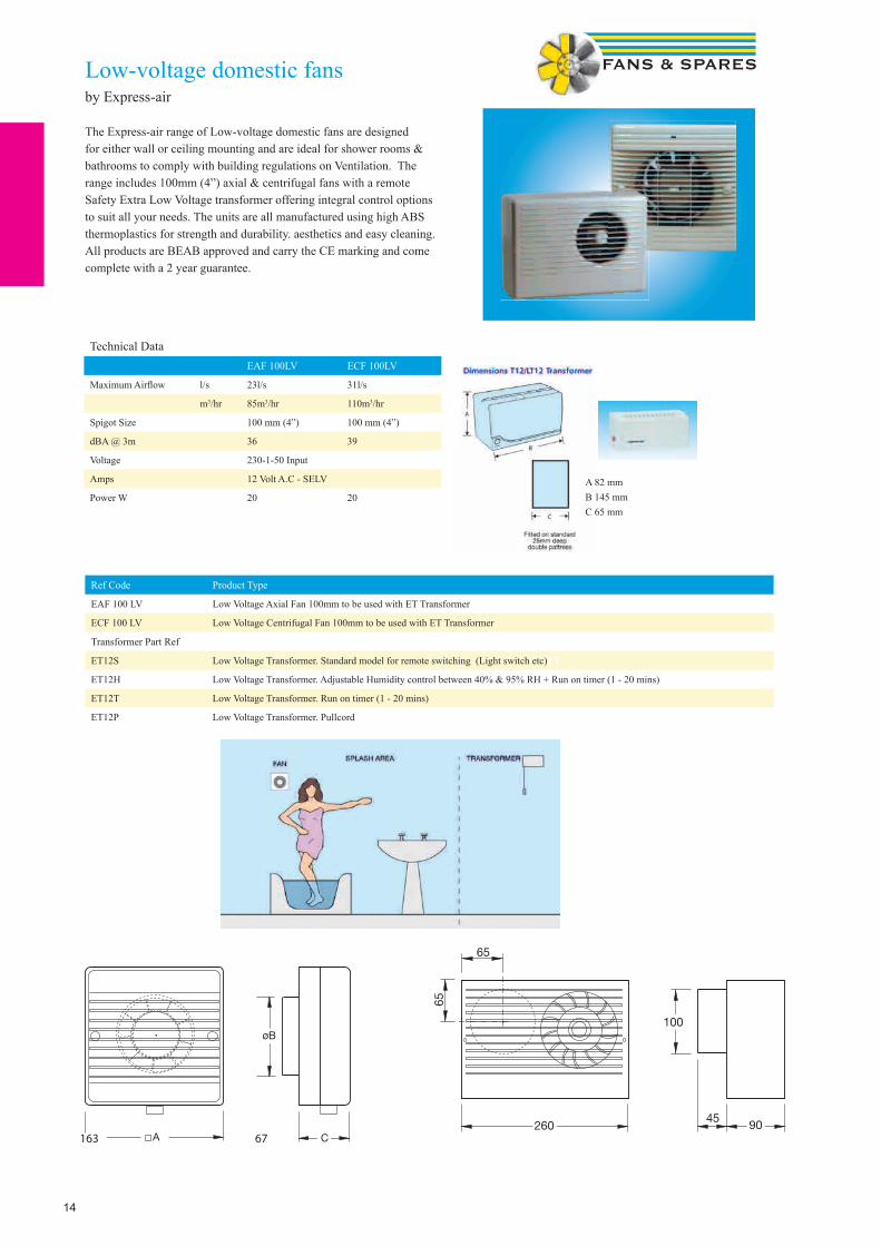
Low-voltage domestic fansby Express-air
The Express-air range of Low-voltage domestic fans are designed for either wall or ceiling mounting and are ideal for shower rooms & bathrooms to comply with building regulations on Ventilation. The range includes 100mm (4”) axial & centrifugal fans with a remote Safety Extra Low Voltage transformer offering integral control options to suit all your needs. The units are all manufactured using high ABS thermoplastics for strength and durability. aesthetics and easy cleaning. All products are BEAB approved and carry the CE marking and come complete with a 2 year guarantee.
Technical DataEAF 100LV ECF 100LV
Maximum Airfl ow l/s 23l/s 31l/s
m3/hr 85m3/hr 110m3/hr
Spigot Size 100 mm (4”) 100 mm (4”)
dBA @ 3m 36 39
Voltage 230-1-50 Input
Amps 12 Volt A.C - SELV
Power W 20 20
Ref Code Product Type
EAF 100 LV Low Voltage Axial Fan 100mm to be used with ET Transformer
ECF 100 LV Low Voltage Centrifugal Fan 100mm to be used with ET Transformer
Transformer Part Ref
ET12S Low Voltage Transformer. Standard model for remote switching (Light switch etc)ET
ET12H Low Voltage Transformer. Adjustable Humidity control between 40% & 95% RH + Run on timer (1 - 20 mins)
ET12T Low Voltage Transformer. Run on timer (1 - 20 mins)
ET12P Low Voltage Transformer. Pullcord
163 67
A 82 mmB 145 mmC 65 mm
15
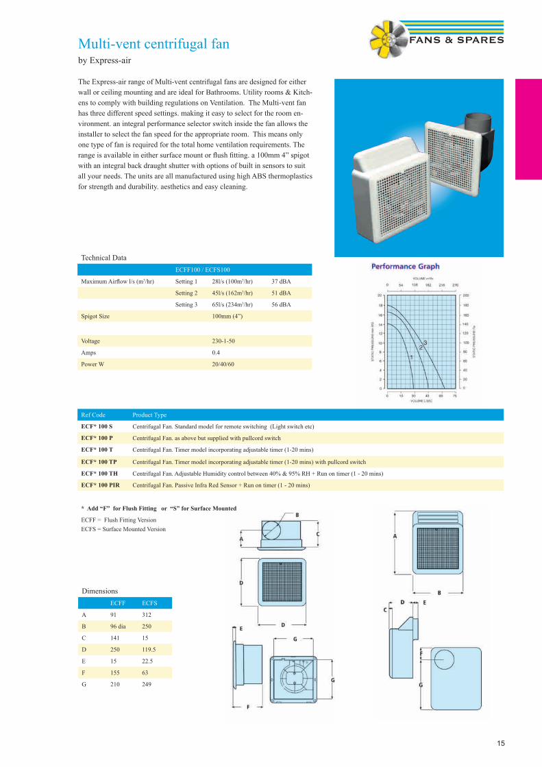
Multi-vent centrifugal fanby Express-air
The Express-air range of Multi-vent centrifugal fans are designed for either wall or ceiling mounting and are ideal for Bathrooms. Utility rooms & Kitch-ens to comply with building regulations on Ventilation. The Multi-vent fan has three different speed settings. making it easy to select for the room en-vironment. an integral performance selector switch inside the fan allows the installer to select the fan speed for the appropriate room. This means only one type of fan is required for the total home ventilation requirements. The range is available in either surface mount or flush fitting. a 100mm 4” spigot with an integral back draught shutter with options of built in sensors to suit all your needs. The units are all manufactured using high ABS thermoplastics for strength and durability. aesthetics and easy cleaning.
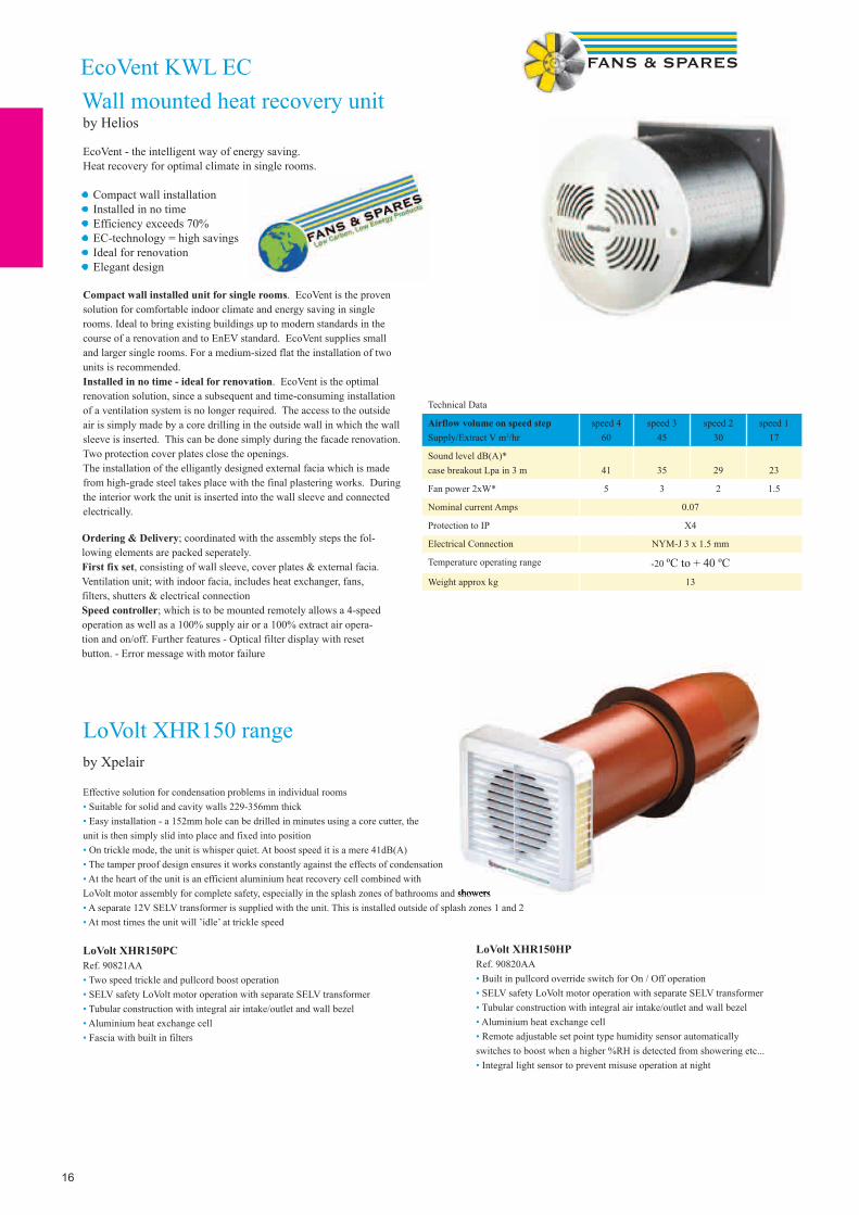
Technical DataECFF100 / ECFS100
Maximum Airflow l/s (m3/hr) Setting 1 28l/s (100m3/hr) 37 dBA
Setting 2 45l/s (162m3/hr) 51 dBA
Setting 3 65l/s (234m3/hr) 56 dBA
Spigot Size 100mm (4”)
Voltage 230-1-50
Amps 0.4
Power W 20/40/60
Ref Code Product Type
ECF* 100 S Centrifugal Fan. Standard model for remote switching (Light switch etc)
ECF* 100 P Centrifugal Fan. as above but supplied with pullcord switch
ECF* 100 T Centrifugal Fan. Timer model incorporating adjustable timer (1-20 mins)
ECF* 100 TP Centrifugal Fan. Timer model incorporating adjustable timer (1-20 mins) with pullcord switch
ECF* 100 TH Centrifugal Fan. Adjustable Humidity control between 40% & 95% RH + Run on timer (1 - 20 mins)
ECF* 100 PIR Centrifugal Fan. Passive Infra Red Sensor + Run on timer (1 - 20 mins)
* Add “F” for Flush Fitting or “S” for Surface Mounted
ECFF = Flush Fitting VersionECFS = Surface Mounted Version
DimensionsECFF ECFS
A 91 312
B 96 dia 250
C 141 15
D 250 119.5
E 15 22.5
F 155 63
G 210 249
16
Technical Data
Airflow volume on speed stepSupply/Extract V m3/hr
speed 460
speed 345
speed 230
speed 117
Sound level dB(A)*case breakout Lpa in 3 m 41 35 29 23
Fan power 2xW* 5 3 2 1.5
Nominal current Amps 0.07
Protection to IP X4
Electrical Connection NYM-J 3 x 1.5 mm
Temperature operating range -20 ºC to + 40 ºCWeight approx kg 13
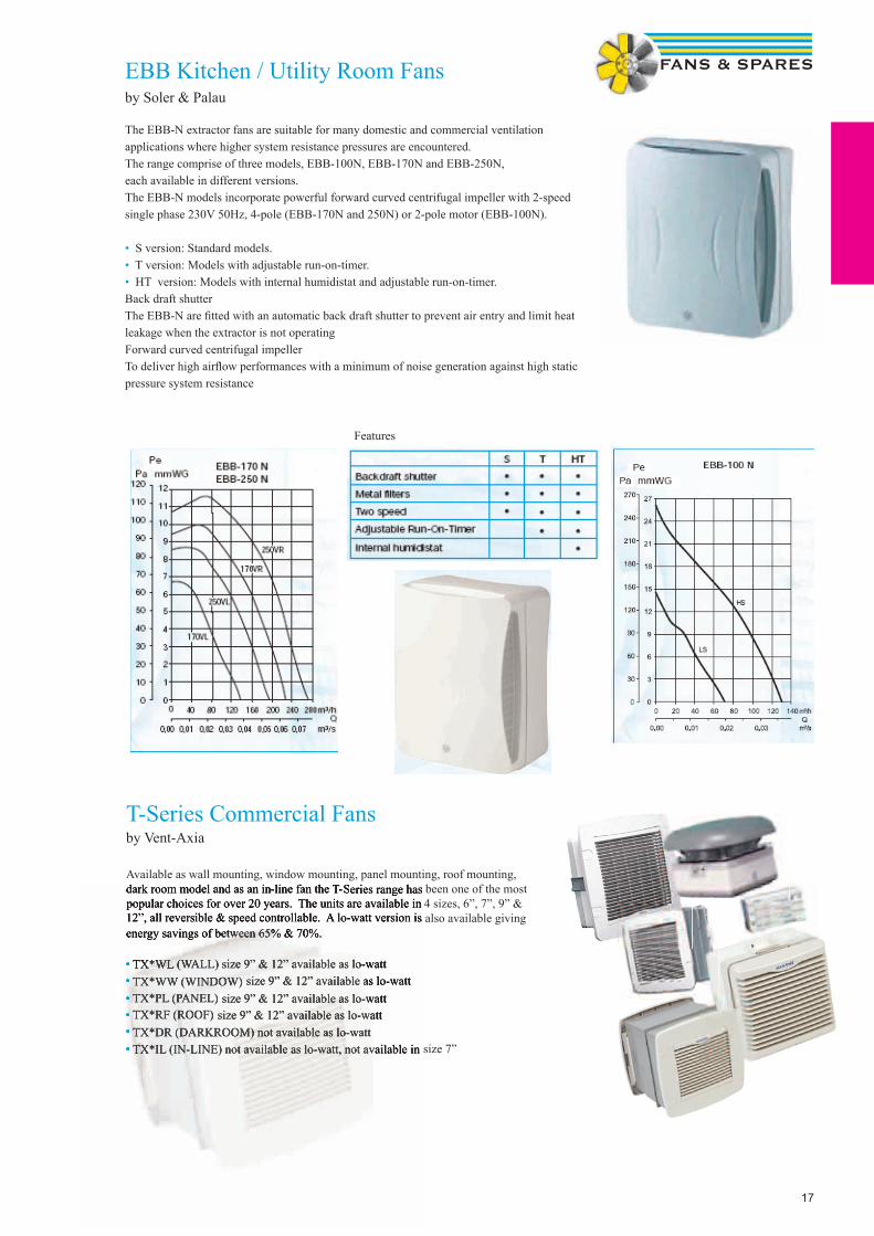
EcoVent KWL EC Wall mounted heat recovery unitby Helios
EcoVent - the intelligent way of energy saving.Heat recovery for optimal climate in single rooms.
• Compact wall installation• Installed in no time• Efficiency exceeds 70%• EC-technology = high savings• Ideal for renovation• Elegant design
Ordering & Delivery; coordinated with the assembly steps the fol-lowing elements are packed seperately.First fix set, consisting of wall sleeve, cover plates & external facia.Ventilation unit; with indoor facia, includes heat exchanger, fans, filters, shutters & electrical connectionSpeed controller; which is to be mounted remotely allows a 4-speed operation as well as a 100% supply air or a 100% extract air opera-tion and on/off. Further features - Optical filter display with reset button. - Error message with motor failure
Compact wall installed unit for single rooms. EcoVent is the proven solution for comfortable indoor climate and energy saving in single rooms. Ideal to bring existing buildings up to modern standards in the course of a renovation and to EnEV standard. EcoVent supplies small and larger single rooms. For a medium-sized flat the installation of two units is recommended.Installed in no time - ideal for renovation. EcoVent is the optimal renovation solution, since a subsequent and time-consuming installation of a ventilation system is no longer required. The access to the outside air is simply made by a core drilling in the outside wall in which the wall sleeve is inserted. This can be done simply during the facade renovation. Two protection cover plates close the openings.The installation of the elligantly designed external facia which is made from high-grade steel takes place with the final plastering works. During the interior work the unit is inserted into the wall sleeve and connected electrically.
LoVolt XHR150 rangeby Xpelair
Effective solution for condensation problems in individual rooms• Suitable for solid and cavity walls 229-356mm thick• Easy installation - a 152mm hole can be drilled in minutes using a core cutter, theunit is then simply slid into place and fixed into position• On trickle mode, the unit is whisper quiet. At boost speed it is a mere 41dB(A)• The tamper proof design ensures it works constantly against the effects of condensation• At the heart of the unit is an efficient aluminium heat recovery cell combined withLoVolt motor assembly for complete safety, especially in the splash zones of bathrooms and showers• A separate 12V SELV transformer is supplied with the unit. This is installed outside of splash zones 1 and 2• At most times the unit will ’idle’ at trickle speed
LoVolt XHR150PCRef. 90821AA• Two speed trickle and pullcord boost operation• SELV safety LoVolt motor operation with separate SELV transformer• Tubular construction with integral air intake/outlet and wall bezel• Aluminium heat exchange cell• Fascia with built in filters
LoVolt XHR150HPRef. 90820AA• Built in pullcord override switch for On / Off operation• SELV safety LoVolt motor operation with separate SELV transformer• Tubular construction with integral air intake/outlet and wall bezel• Aluminium heat exchange cell• Remote adjustable set point type humidity sensor automatically switches to boost when a higher %RH is detected from showering etc...• Integral light sensor to prevent misuse operation at night
LoVolt motor assembly for complete safety, especially in the splash zones of bathrooms and showers
Heat recovery for optimal climate in single rooms.
17
EBB Kitchen / Utility Room Fansby Soler & Palau
The EBB-N extractor fans are suitable for many domestic and commercial ventilationapplications where higher system resistance pressures are encountered. The range comprise of three models, EBB-100N, EBB-170N and EBB-250N,each available in different versions. The EBB-N models incorporate powerful forward curved centrifugal impeller with 2-speed single phase 230V 50Hz, 4-pole (EBB-170N and 250N) or 2-pole motor (EBB-100N). • S version: Standard models. • T version: Models with adjustable run-on-timer. • HT version: Models with internal humidistat and adjustable run-on-timer.Back draft shutter The EBB-N are fi tted with an automatic back draft shutter to prevent air entry and limit heat leakage when the extractor is not operating Forward curved centrifugal impeller To deliver high airfl ow performances with a minimum of noise generation against high static pressure system resistance
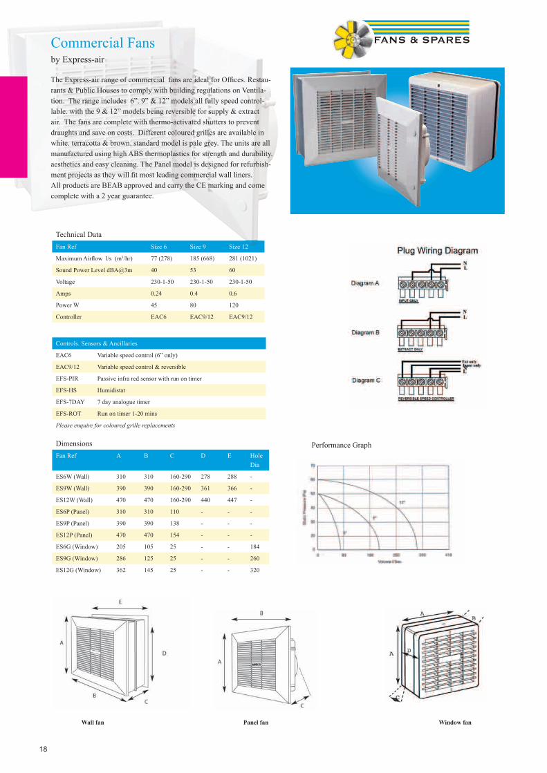
T-Series Commercial Fansby Vent-Axia
Available as wall mounting, window mounting, panel mounting, roof mounting, dark room model and as an in-line fan the T-Series range has been one of the most popular choices for over 20 years. The units are available in 4 sizes, 6”, 7”, 9” & 12”, all reversible & speed controllable. A lo-watt version is also available giving energy savings of between 65% & 70%.
• TX*WL (WALL) size 9” & 12” available as lo-watt• TX*WW (WINDOW) size 9” & 12” available as lo-watt• TX*PL (PANEL) size 9” & 12” available as lo-watt• TX*RF (ROOF) size 9” & 12” available as lo-watt• TX*DR (DARKROOM) not available as lo-watt• TX*IL (IN-LINE) not available as lo-watt, not available in size 7”
dark room model and as an in-line fan the T-Series range has been one of the most popular choices for over 20 years. The units are available in 4 sizes, 6”, 7”12”, all reversible & speed controllable. A lo-watt version is also available giving energy savings of between 65% & 70%.
• TX*WL (WALL) size 9” & 12” available as lo-watt• TX*WW (WINDOW) size 9” & 12” available as lo-watt• TX*PL (PANEL) size 9” & 12” available as lo-watt• TX*RF (ROOF) size 9” & 12” available as lo-watt• TX*DR (DARKROOM) not available as lo-watt• TX*IL (IN-LINE) not available as lo-watt, not available in size
Features
18
Technical DataFan Ref Size 6 Size 9 Size 12
Maximum Airfl ow l/s (m3/hr) 77 (278) 185 (668) 281 (1021)
Sound Power Level dBA@3m 40 53 60
Voltage 230-1-50 230-1-50 230-1-50
Amps 0.24 0.4 0.6
Power W 45 80 120
Controller EAC6 EAC9/12 EAC9/12
Controls. Sensors & Ancillaries
EAC6 Variable speed control (6” only)
EAC9/12 Variable speed control & reversible
EFS-PIR Passive infra red sensor with run on timer
EFS-HS Humidistat
EFS-7DAY 7 day analogue timer
EFS-ROT Run on timer 1-20 mins
Please enquire for coloured grille replacements
Performance GraphDimensionsFan Ref A B C D E Hole
Dia
ES6W (Wall) 310 310 160-290 278 288 -
ES9W (Wall) 390 390 160-290 361 366 -
ES12W (Wall) 470 470 160-290 440 447 -
ES6P (Panel) 310 310 110 - - -
ES9P (Panel) 390 390 138 - - -
ES12P (Panel) 470 470 154 - - -
ES6G (Window) 205 105 25 - - 184
ES9G (Window) 286 125 25 - - 260
ES12G (Window) 362 145 25 - - 320
Wall fan Panel fan Window fan
Commercial Fansby Express-air
The Express-air range of commercial fans are ideal for Offi ces. Restau-rants & Public Houses to comply with building regulations on Ventila-tion. The range includes 6”. 9” & 12” models all fully speed control-lable. with the 9 & 12” models being reversible for supply & extract air. The fans are complete with thermo-activated shutters to prevent draughts and save on costs. Different coloured grilles are available in white. terracotta & brown. standard model is pale grey. The units are all manufactured using high ABS thermoplastics for strength and durability. aesthetics and easy cleaning. The Panel model is designed for refurbish-ment projects as they will fi t most leading commercial wall liners. All products are BEAB approved and carry the CE marking and come complete with a 2 year guarantee.
19
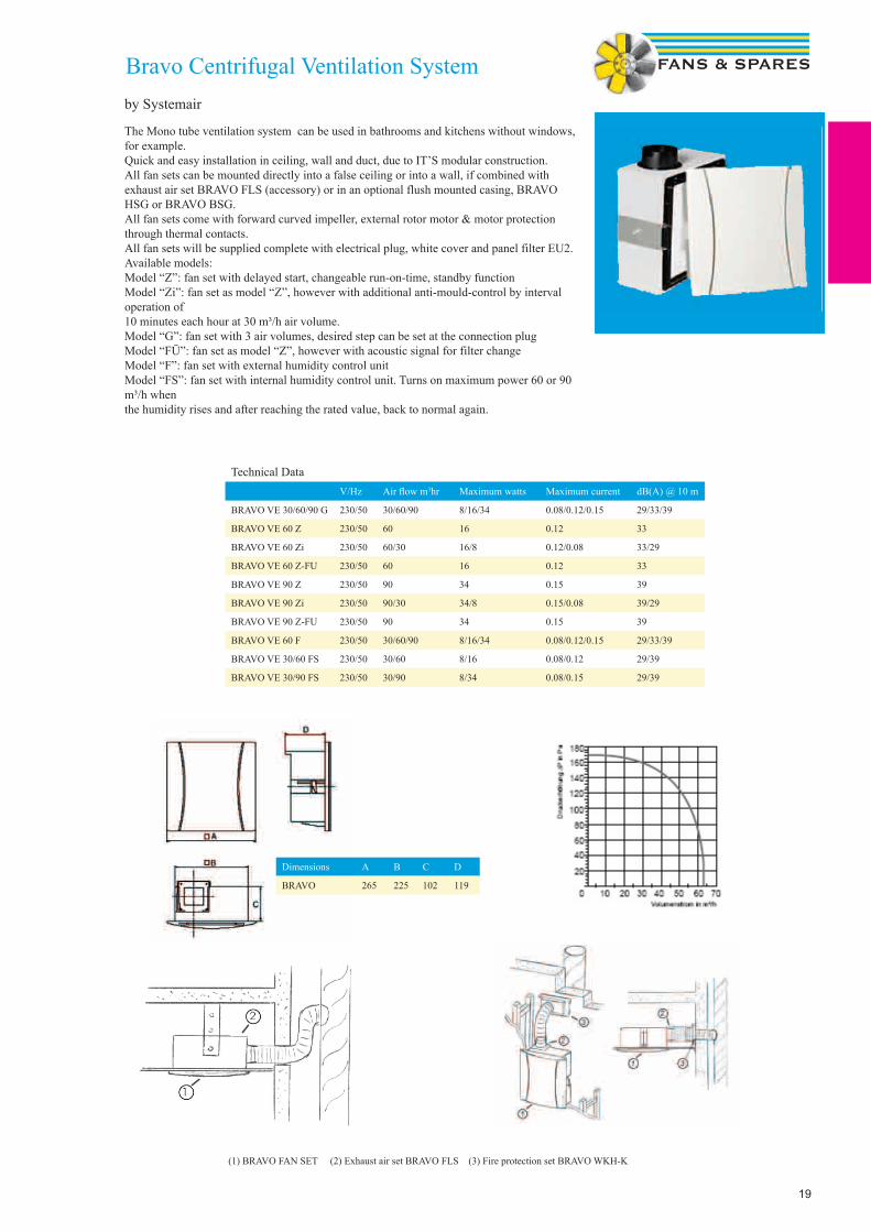
The Mono tube ventilation system can be used in bathrooms and kitchens without windows, for example.Quick and easy installation in ceiling, wall and duct, due to IT’S modular construction. All fan sets can be mounted directly into a false ceiling or into a wall, if combined with exhaust air set BRAVO FLS (accessory) or in an optional flush mounted casing, BRAVO HSG or BRAVO BSG. All fan sets come with forward curved impeller, external rotor motor & motor protection through thermal contacts.All fan sets will be supplied complete with electrical plug, white cover and panel filter EU2.Available models:Model “Z”: fan set with delayed start, changeable run-on-time, standby functionModel “Zi”: fan set as model “Z”, however with additional anti-mould-control by interval operation of10 minutes each hour at 30 m³/h air volume.Model “G”: fan set with 3 air volumes, desired step can be set at the connection plugModel “FÜ”: fan set as model “Z”, however with acoustic signal for filter changeModel “F”: fan set with external humidity control unitModel “FS”: fan set with internal humidity control unit. Turns on maximum power 60 or 90 m³/h whenthe humidity rises and after reaching the rated value, back to normal again.
Technical DataV/Hz Air fl ow m3hr Maximum watts Maximum current dB(A) @ 10 m
BRAVO VE 30/60/90 G 230/50 30/60/90 8/16/34 0.08/0.12/0.15 29/33/39
BRAVO VE 60 Z 230/50 60 16 0.12 33
BRAVO VE 60 Zi 230/50 60/30 16/8 0.12/0.08 33/29
BRAVO VE 60 Z-FU 230/50 60 16 0.12 33
BRAVO VE 90 Z 230/50 90 34 0.15 39
BRAVO VE 90 Zi 230/50 90/30 34/8 0.15/0.08 39/29
BRAVO VE 90 Z-FU 230/50 90 34 0.15 39
BRAVO VE 60 F 230/50 30/60/90 8/16/34 0.08/0.12/0.15 29/33/39
BRAVO VE 30/60 FS 230/50 30/60 8/16 0.08/0.12 29/39
BRAVO VE 30/90 FS 230/50 30/90 8/34 0.08/0.15 29/39
Bravo Centrifugal Ventilation Systemby Systemair
(1) BRAVO FAN SET (2) Exhaust air set BRAVO FLS (3) Fire protection set BRAVO WKH-K
Dimensions A B C D
BRAVO 265 225 102 119

20
Centralised ducting systemby S&P
The Soler & Palau Centralised Ducting System (EACE-5) provides con-tinuous mechanical ventilation throughout the entire house from a single extraction unit and can be used in up to fi ve individual rooms. Made from strong reinforced plastic it is very lightweight. making it easy to install in a loft or ceiling void. A two speed motor is fi tted as standard to enable trickle & boost operation via a switch (Available separately). The range offers a standard model & a Humidity model. which switches the fan on at high speed when the humidity reaches a set point. The fan unit is supplied with three extraction inlets. two 80mm inlets. one with a fl ow regulator at 15m3/hr for toilets and the other at 30m3/hr for bathrooms. There is a 125mm spigot also for Kitchens with tabs to regulate the air fl ow from 45 - 135m3/hr. plus two further plugged 80mm inlets for larger applications. all discharging from one 125mm extract duct through either a wall or roof terminal.
Air valves. Flexible ducting. Two speed switches & Flow regula-tors are all available as separate items.
Electrical data: 220-240V -A.C. 50 Hz. consuming 24 watts on minimum speed & 65 watts on maximum speed. A double pole isolating switch. having a contact separation of at least 3mm in all poles. must be used with a 3 amp fuse fi tted. to comply with current IEE regulations. The fan unit must not be accessible to a person using either the shower or bath.
Top of the energy classThe best SAP Appendix Q eligible product with an incredible 0.16w/l/s* performance which will help reduce DER’s in SAP and contribute to achieving Level 3 and above of the Code for Sustainable Homes. Complete controlA continuously running ventilation system for the whole house that actively contributes to indoor air quality, controlled via a wired in remote switch to control trickle and boost speeds. Not seen and not heardA completely discreet system, centrally mounted in a cupboard means no more nuisance running noise. Space saving5th extract point can be located at bottom of unit (requires cut out on site) for easier connection to ducting in applications with limited space. A perfect fitCompact design (one of the smallest on the market) makes it ideal for apartments and small properties that usually don’t have the window space for all of the trickle vents required with traditional ‘on and off’ extract fans (System 1). No fuss installation and commissioningOne of the fastest units to connect and commission on site. 100% variable motor speed options for trickle and boost speeds adjusted through speed pots located on fan body. (medium speed will be based on mid-point between selected trickle and boost speeds). From inside to outEnergy efficient EC motor, 5 extract spigots, clever motor assembly design which can be easily removed once isolated, allowing for cleaning and maintenance if necessary.
Centralised ducting system CMEV.4eby Greenwood Airvac
/hr. plus two further plugged 80mm inlets for larger applications. all discharging from one 125mm extract duct through either a wall or roof terminal.
Air valves. Flexible ducting. Two speed switches & Flow regula-tors are all available as separate items.
strong reinforced plastic it is very lightweight. making it easy to install in a loft or ceiling void. A two speed motor is fi tted as standard to enable trickle & boost operation via a switch (Available separately). The range offers a standard model & a Humidity model. which switches the fan on at high speed when the humidity reaches a set point. The fan unit is supplied with three extraction inlets. two 80mm inlets. one with a fl ow regulator at 15m3/hr for toilets and the other at 30m3/hr for bathrooms. There is a 125mm spigot also for Kitchens with tabs to regulate the air fl ow from 45 - 135m3

21
EACE-3 Central Extract Systemby Express-air
The Express-air Centralised Ducting System (EACE-3) provides continuous mechanical ventilation throughout the entire house from a single extraction unit and can be used in up to three individual rooms. Made from strong ABS plastic it is very lightweight. making it easy to install in a loft or ceiling void. A three speed fan offers trickle. medium & boost operation via a switch (available separate-ly). The fan unit is supplied with three extraction inlets. all 125mm which discharge from one 125mm extract duct through either a wall or roof terminal. A slimline version is also available to suit applica-tions where space is at a premium. the unit is only 185mm high and is manufactured with three extract points suitable for use with 110mm x 54mm or 204mm x 60mm fl at duct or a mixture of both.
Technical Data Model EACE-3S EACE-3T EACE-3DC
Static Pa @ 225m3/hr 151 Pa 400 Pa 400 Pa
Output High 41 W 73 W 24.4 W
Medium 22 W 40 W 9.9 W
Low 12 W 13 W 5.1 W
Max amperage 0.18 amps 0.23 amps 0.18 amps
Voltage 230-1-51 230-1-50 230-1-50
Weight 3.4kg 3.5kg 3.5kg
Dimensions
EACE-3 S EACE-3 T EACE-3 DC
22
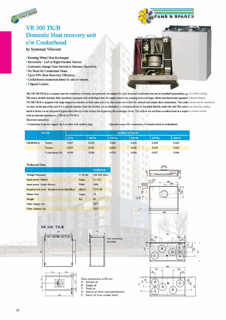
VR 300 TK/BDomestic Heat recovery unit c/w Cookerhood by Systemair Villavent
• Rotating Wheel Heat Exchanger. • Reversible - Left or Right Handed Version.• Automatic change from Normal to Summer Operation.• No Need for Condensate Drain.• Up to 84% Heat Recovery Effi ciency.• Cookerhood connection direct to unit or remote.• 3 Speed Control.
VR Unit Air fl ow m3/s @ Pa
50 Pa 100 Pa 150 Pa 200 Pa 250 Pa 300 Pa
VR300TK/B Supply 0.057 0.050 0.044 0.036 0.028 0.020
Extract 0.057 0.051 0.044 0.036 0.029 0.020
Cookerhood Ext 0.090 0.084 0.076 0.068 0.057 0.044
Technical Data VR300TK/B
Voltage Frequency V/ 50 Hz 230-240 50Hz
Input power. Motors Watts 2 x 120
Input power. Heater Battery Watts 1000
Sound power level - Breakout (Low/Min/Max) dB(A) 35/41/44
Mains Fuse Amps 10
Weight Kg 45
Filter. Supply Air EU7
Filter. Exhaust Air EU5
The VR 300 TK/B is a compact unit for ventilation of homes and primarily developed for wall mounted installation but can be installed horizontally e.g. in a false ceiling.
The unit is double skinned, fully insulated, equipped with centrifugal fans for supply/extract air, rotating heat exchanger, fi lters and thermostat operated re-heater battery.
VR 300 TK/B is quipped with large inspection hatches on both sides and is by that means reversible for optimal and simple duct connections. The cooker hood can be connected
via duct on the top of the unit if it is placed separate from the kitchen. As an alternative, a cookerhood can be installed directly under the unit.The extract air from the cooker-
hood is drawn via an integrated bypass duct directly to the extract fan bypassing the exchanger block. The airfl ow are set from a cooker hood or a separate control switch
with an internal transformer, CTK/B ot CTK/B-S.
Electrical connection
• Connection to power supply via 1 m cable with earthed plug • Special contact for connection of control switch or cookerhood
23
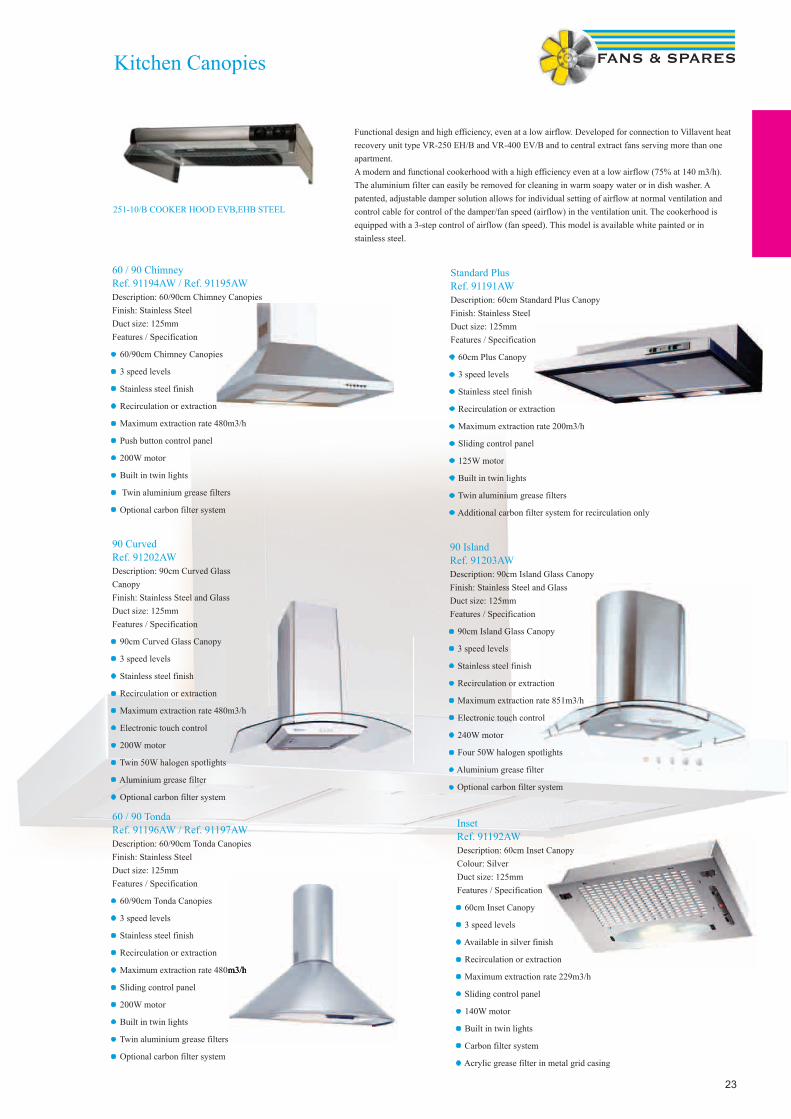
Functional design and high efficiency, even at a low airflow. Developed for connection to Villavent heat recovery unit type VR-250 EH/B and VR-400 EV/B and to central extract fans serving more than one apartment.A modern and functional cookerhood with a high efficiency even at a low airflow (75% at 140 m3/h). The aluminium filter can easily be removed for cleaning in warm soapy water or in dish washer. A patented, adjustable damper solution allows for individual setting of airflow at normal ventilation and control cable for control of the damper/fan speed (airflow) in the ventilation unit. The cookerhood is equipped with a 3-step control of airflow (fan speed). This model is available white painted or in stainless steel.
Kitchen Canopies
251-10/B COOKER HOOD EVB,EHB STEEL
90 CurvedRef. 91202AWDescription: 90cm Curved Glass CanopyFinish: Stainless Steel and GlassDuct size: 125mmFeatures / Specification
• 90cm Curved Glass Canopy
• 3 speed levels
• Stainless steel finish
• Recirculation or extraction
• Maximum extraction rate 480m3/h
• Electronic touch control
• 200W motor
• Twin 50W halogen spotlights
• Aluminium grease filter
• Optional carbon filter system
90 IslandRef. 91203AWDescription: 90cm Island Glass CanopyFinish: Stainless Steel and GlassDuct size: 125mmFeatures / Specification
• 90cm Island Glass Canopy
• 3 speed levels
• Stainless steel finish
• Recirculation or extraction
• Maximum extraction rate 851m3/h
• Electronic touch control
• 240W motor
• Four 50W halogen spotlights
• Aluminium grease filter
• Optional carbon filter system
60 / 90 ChimneyRef. 91194AW / Ref. 91195AWDescription: 60/90cm Chimney CanopiesFinish: Stainless SteelDuct size: 125mmFeatures / Specification
• 60/90cm Chimney Canopies
• 3 speed levels
• Stainless steel finish
• Recirculation or extraction
• Maximum extraction rate 480m3/h
• Push button control panel
• 200W motor
• Built in twin lights
• Twin aluminium grease filters
• Optional carbon filter system
InsetRef. 91192AWDescription: 60cm Inset CanopyColour: SilverDuct size: 125mmFeatures / Specification
• 60cm Inset Canopy
• 3 speed levels
• Available in silver finish
• Recirculation or extraction
• Maximum extraction rate 229m3/h
• Sliding control panel
• 140W motor
• Built in twin lights
• Carbon filter system
• Acrylic grease filter in metal grid casing
Standard PlusRef. 91191AWDescription: 60cm Standard Plus CanopyFinish: Stainless SteelDuct size: 125mmFeatures / Specification
• 60cm Plus Canopy
• 3 speed levels
• Stainless steel finish
• Recirculation or extraction
• Maximum extraction rate 200m3/h
• Sliding control panel
• 125W motor
• Built in twin lights
• Twin aluminium grease filters
• Additional carbon filter system for recirculation only
60 / 90 TondaRef. 91196AW / Ref. 91197AWDescription: 60/90cm Tonda CanopiesFinish: Stainless SteelDuct size: 125mmFeatures / Specification
• 60/90cm Tonda Canopies
• 3 speed levels
• Stainless steel finish
• Recirculation or extraction
• Maximum extraction rate 480m3/h
• Sliding control panel
• 200W motor
• Built in twin lights
• Twin aluminium grease filters
• Optional carbon filter system
Maximum extraction rate 480m3/h

24
Industrial fans

25
TD-MIXVENT in-line mixed fl ow fanby Soler &Palau
• Silent running and certifi ed. guaranteed performance• Compact overall dimensions• Protection rating IPX4• Two speeds (except TD 4000 & 6000)• Adjustable Run on Timer (These models are not speed controllable)• Models 160 - 800 have polypropylene casing, while models 1000 - 6000 have steel casings• Self-extinguishing V0 plastic• Eco-friendly• Speed controllable• Low Carbon - Ecowatt version availableThe Soler & Palau range of in-line mixed fl ow duct fans are manufactured in tough reinforced plastic (from 160 to 800 models) or with metal casing steel fi nished in a tough epoxy-polyester paint coating (from 1000 to 6000 models). The unique design of the support bracket allows the motor and impeller assembly to be fi tted or removed without dismantling the adjacent ducting.
Fan TD-MIXVENT
DuctDiameter
Voltage Speed Airfl ow m3/sec@Static Pressure Pa. Power Current SoundPressureLevel *
Ref mm RPM 0 Pa 50 Pa 100 Pa 150 Pa 200 Pa 250 Pa Watts Amps dBA
TD-160/100 N SILENT 100 230-1-50 Min 2200 0.039 0.013 - - - - 12 0.10 21Max 2500 0.05 0.0286 0.002 - - - 20 0.16 24
TD-250/100 100 230-1-50 Min 1850 0.047 0.025 0.001 - - - 18 0.10 26Max 2200 0.066 0.052 0.015 - - - 24 0.11 31
TD-350/125 125 230-1-50 Min 1900 0.075 0.045 0.01 - - - 22 0.10 28Max 2250 0.099 0.08 0.032 0.001 - 30 0.13 33
TD-500/150 150 230-1-50 Min 1950 0.122 0.1 0.081 0.05 0.02 - 44 0.19 29Max 2500 0.159 0.15 0.14 0.125 0.04 0.02 50 0.22 33
TD-500/160 160 230-1-50 Min 1950 0.122 0.1 0.081 0.05 0.02 44 0.19 29Max 2500 0.159 0.15 0.14 0.125 0.04 0.02 50 0.22 33
TD-800/200 200 230-1-50 Min 2000 0.22 0.19 0.165 0.145 0.075 0.04 100 0.45 33Max 2500 0.28 0.26 0.25 0.23 0.2 0.09 120 0.50 39
TD-1300/250 250 230-1-50 Min 2000 0.294 0.25 0.22 0.17 0.14 0.1 140 0.60 39Max 2520 0.355 0.33 0.31 0.275 0.25 0.22 180 0.80 43
TD-2000/315 315 230-1-50 Min 2000 0.31 0.26 0.23 0.155 0.12 0.09 160 0.80 42Max 2700 0.4 0.37 0.35 0.325 0.3 0.27 225 1.20 47
TD-4000/355 355 230-1-50 Max 1400 1.027 0.98 0.9 0.79 0.65 0.09 345 1.53 44TD-6000/400 400 230-1-50 Max 1400 1.527 1.4 1.35 1.25 1.1 0.85 665 2.97 44*Sound pressure level radiated at 3 m @ free air conditions with rigid ducts at the inlet & outlet
DimensionsA B C D E F G H kg
TD-160/100 N SILENT 232 135.5 95.5 97 82 96 47.5 5 1.4
TD-250/100 303 176 115 123 100 90 80 60 2.0
TD-350/125 258 176 115 123 100 90 80 60 2.0
TD-500/150 295 200 127 147 112 130 80 60 2.7
TD-500/160 275 200 127 157 112 130 80 60 2.7
TD-800/200 302 217 141 198 124 140 100 94 4.9
TD-1300/250 386 272 192 248 155 168 145 140 9.4
TD-2000/315 450 336 224 312 188 210 182 178 14.0
TD-4000/355 377 238 451 224 426 354 150 368 19.0
TD-6000/400 450 249 492 267 487 399 160 425 26.0
TD160/100 N SILENTTD250 - TD2000TD4000 & TD6000
26
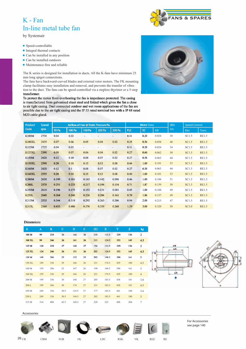
K - FanIn-line metal tube fanby Systemair
K A B C D E (F) X Y Z kg
100 M 99 218 26 166 26 218 112.5 329 136 2
100 XL 99 246 26 161 26 213 124.5 353 145 4.5
125 M 124 218 27 142 27 196 112.5 329 136 2
125 XL 124 246 26 151 26 203 124.5 353 145 4.5
150 M 149 286 25 152 25 202 148.5 390 161 3
150 XL 149 336 29 166 26 221 174.5 429 180 4.5
160 M 159 286 25 147 26 198 148.5 390 161 3
160 XL 159 336 29 166 26 221 174.5 429 180 4
200 M 199 336 30 148 27 205 183.5 438 181 3.8
200 L 199 366 30 174 27 231 183.5 438 181 4.5
250 M 249 336 30.5 119.5 27 177 183.5 441 180 3.6
250 L 249 336 30.5 144.5 27 202 183.5 441 180 5
315 M 314 408 42.5 160.5 27 220 222 498 204 7
Dimensions
Accessories
Product
Code
Speed
rpm
Airfl ow m3/sec @ Static Pressure Pa. Motor Data dBA
3m
Speed Control
50 Pa 100 Pa 150 Pa 200 Pa 300 Pa FLC SC kW Elec Trans
K100M 2730 0.04 0.02 - - - 0.11 0.28 0.024 38 SC1.5 RE1.5
K100XL 2435 0.07 0.06 0.05 0.04 0.02 0.25 0.56 0.058 48 SC1.5 RE1.5
K125M 2725 0.04 0.03 - - - 0.11 0.28 0.024 34 SC1.5 RE1.5
K125XL 2390 0.08 0.07 0.06 0.04 0.02 0.27 0.60 0.062 50 SC1.5 RE1.5
K150M 2420 0.12 0.10 0.08 0.07 0.02 0.27 0.58 0.063 44 SC1.5 RE1.5
K150XL 2590 0.20 0.18 0.15 0.13 0.08 0.44 1.00 0.101 53 SC1.5 RE1.5
K160M 2420 0.12 0.1 0.08 0.07 0.02 0.27 0.58 0.063 44 SC1.5 RE1.5
K160XL 2555 0.20 0.18 0.15 0.13 0.08 0.44 1.00 0.101 53 SC1.5 RE1.5
K200M 2630 0.199 0.181 0.163 0.142 0.096 0.46 1.00 0.106 51 SC1.5 RE1.5
K200L 2570 0.251 0.233 0.217 0.196 0.154 0.71 1.87 0.159 50 SC1.5 RE1.5
K250M 2610 0.196 0.175 0.153 0.131 0.081 0.45 1.00 0.104 49 SC1.5 RE1.5
K250L 2640 0.264 0.246 0.226 0.206 0.161 0.70 1.86 0.157 49 SC1.5 RE1.5
K315M 2535 0.344 0.318 0.292 0.263 0.206 0.94 2.00 0.215 47 SC1.5 RE1.5
K315L 2360 0.433 0.406 0.376 0.339 0.268 1.39 3.00 0.320 50 SC3.0 RE1.5
For Accessoriessee page 140
• Speed-controllable• Integral thermal contacts• Can be installed in any position• Can be installed outdoors• Maintenance-free and reliable
The K series is designed for installation in ducts. All the K-fans have minimum 25 mm long spigot connections.The fans have backward-curved blades and external rotor motors. The FK mounting clamp facilitates easy installation and removal, and prevents the transfer of vibra-tion to the duct. The fans can be speed-controlled via a stepless thyristor or a 5-step transformer.To protect the motor from overheating the fan is impedance protected. The casing is manufactured from galvanised sheet steel and folded which gives the fan a close to air tight casing. Duct connected outdoor and wet room applications of the fan are possible due to the air tight casing and the IP 55 rated terminal box with a IP 68 rated M20 cable gland.
CB CBM FGR FK LDC RSK VK REE RE
K A B C D E (F) X Y Z kg
100 M 99 218 26 166 26 218 112.5 329 136 2
100 XL 99 246 26 161 26 213 124.5 353 145 4.5
125 M 124 218 27 142 27 196 112.5 329 136 2
125 XL 124 246 26 151 26 203 124.5 353 145 4.5
150 M 149 286 25 152 25 202 148.5 390 161 3
Dimensions
Product
Code
Speed
rpm
Airfl ow m3/sec @ Static Pressure Pa. Motor Data
50 Pa 100 Pa 150 Pa 200 Pa 300 Pa FLC SC
K100M 2730 0.04 0.02 - - - 0.11 0.28
K100XL 2435 0.07 0.06 0.05 0.04 0.02 0.25 0.56
K125M 2725 0.04 0.03 - - - 0.11 0.28
K125XL 2390 0.08 0.07 0.06 0.04 0.02 0.27 0.60
K150M 2420 0.12 0.10 0.08 0.07 0.02 0.27 0.58
K150XL 2590 0.20 0.18 0.15 0.13 0.08 0.44 1.00
K160M 2420 0.12 0.1 0.08 0.07 0.02 0.27 0.58
K160XL 2555 0.20 0.18 0.15 0.13 0.08 0.44 1.00
K200M 2630 0.199 0.181 0.163 0.142 0.096 0.46 1.00
K200L 2570 0.251 0.233 0.217 0.196 0.154 0.71 1.87
K250M 2610 0.196 0.175 0.153 0.131 0.081 0.45 1.00
K250L 2640 0.264 0.246 0.226 0.206 0.161 0.70 1.86
K315M 2535 0.344 0.318 0.292 0.263 0.206 0.94 2.00
K315L 2360 0.433 0.406 0.376 0.339 0.268 1.39 3.00
tion to the duct. The fans can be speed-controlled via a stepless thyristor or a 5-step transformer.To protect the motor from overheating the fan is impedance protected. The casing is manufactured from galvanised sheet steel and folded which gives the fan a close to air tight casing. Duct connected outdoor and wet room applications of the fan are possible due to the air tight casing and the IP 55 rated terminal box with a IP 68 rated M20 cable gland.

27
RVKPlastic in-line centrifugal tube fanby Systemair
Dimensions
Product
Code
Speed
rpm
Airfl ow m3/sec @ Static Pressure Pa. Motor Data dBA @
3m
Speed Control
50 Pa 100 Pa 150 Pa 200 Pa 300 Pa FLC SC kW Elec Trans
RVK 100E2-A1 2480 0.038 0.024 - - - 0.17 0.35 0.029 34 SC 1.5 RE 1.5
RVK 125E2-A1 2468 0.049 0.028 - - - 0.17 0.35 0.029 38 SC 1.5 RE 1.5
RVK 125E2-L2 2436 0.08 0.067 0.054 0.043 0.015 0.26 0.83 0.061 43 SC 1.5 RE 1.5
RVK 150E2-A1 2430 0.106 0.093 0.079 0.062 0.015 0.26 0.83 0.058 43 SC 1.5 RE 1.5
RVK 150E2-L2 2430 0.171 0.155 0.139 0.122 0.083 0.5 1.50 0.112 43 SC 1.5 RE 1.5
RVK 160E2-A1 2530 0.11 0.097 0.082 0.064 0.013 0.26 0.83 0.058 48 SC 1.5 RE 1.5
RVK 160E2-L2 2530 0.186 0.168 0.15 0.13 0.087 0.50 1.50 0.112 48 SC 1.5 RE 1.5
RVK 200E2-A1 2550 0.2 0.181 0.161 0.14 0.09 0.47 1.45 0.107 45 SC 1.5 RE 1.5
RVK 200E2-L2 2580 0.25 0.23 0.21 0.19 0.15 0.71 2.00 0.16 46 SC 1.5 RE 1.5
RVK 250E2-A1 2546 0.21 0.2 0.178 0.154 0.096 0.47 1.45 0.109 48 SC 1.5 RE 1.5
RVK 250E2-L2 2595 0.283 0.264 0.244 0.221 0.173 0.70 2.00 0.159 44 SC 1.5 RE 1.5
RVK 315E2-A1 2387 0.345 0.319 0.292 0.263 0.202 0.77 2.40 0.176 40 SC 1.5 RE 1.5
RVK 315E2-L2 2433 0.48 0.45 0.43 0.4 0.328 1.39 3.20 0.318 45 SC 3.0 RE 1.5
Accessories
RVK A B C D E F G H I J kg
RVK100 99 99 251 30 230 30 271.5 265 60 200 2
RVK125 124 124 251 30 230 30 271.5 265 60 200 2
RVK150 149 149 340.5 30 230 30 271.5 360 60 200 4.7
RVK160 159 159 340.5 30 230 30 271.5 360 60 200 4.7
RVK200E2-A1 199 199 340.5 30 230 30 271.5 360 60 200 4
RVK200E2-L1 199 199 340.5 30 250 30 271.5 360 60 200 4.5
RVK250E2-A1 249 249 340.5 30 230 30 271.5 360 60 200 5
RVK250E2-L1 249 249 340.5 30 250 30 271.5 360 60 200 5.2
RVK315 315 315 405 30 275 30 271.5 430 60 200 7.5
For Accessoriessee page 140
• Speed-controllable• Integral thermal contacts• Can be installed in any position• Inclusive mounting bracket• Maintenance-free and reliable• Suitable for Hydroponics use
The RVK series is designed for installation in ducts.The fans have backward-curved blades and external rotor motors. The FK mounting clamp facilitates easy installation and removal, and prevents the transfer of vibration to the duct. The fans can be speed-controlled via a stepless thyristor or a 5-step transformer. The RVK fans have integral thermal contacts with automatic reset. The casing is manufactured from fibreglass reinforced plastic.
CB CBM FGR FK LDC RSK VK REE RE
28
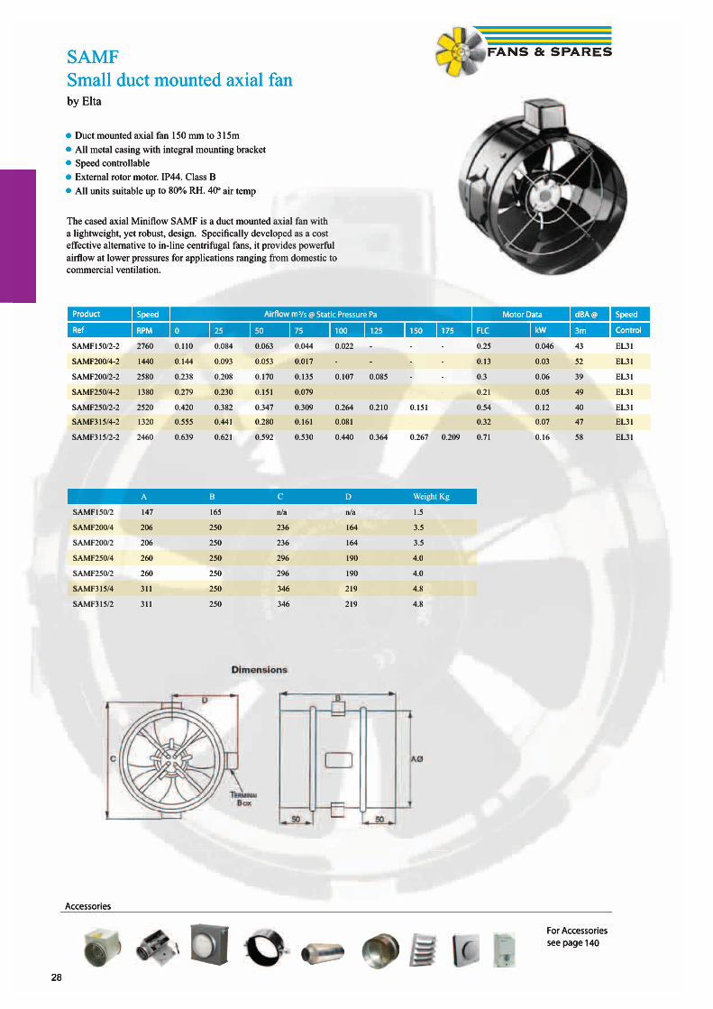
SAMFSmall duct mounted axial fanby Elta
• Duct mounted axial fan 150 mm to 315m • All metal casing with integral mounting bracket• Speed controllable• External rotor motor. IP44. Class B• All units suitable up to 80% RH. 40º air temp
The cased axial Minifl ow SAMF is a duct mounted axial fan with a lightweight, yet robust, design. Specifi cally developed as a cost effective alternative to in-line centrifugal fans, it provides powerful airfl ow at lower pressures for applications ranging from domestic to commercial ventilation.
Product Speed Airfl ow m3/s @ Static Pressure Pa Motor Data dBA @ Speed
Ref RPM 0 25 50 75 100 125 150 175 FLC kW 3m Control
SAMF150/2-2 2760 0.110 0.084 0.063 0.044 0.022 - - - 0.25 0.046 43 EL31
SAMF200/4-2 1440 0.144 0.093 0.053 0.017 - - - - 0.13 0.03 52 EL31
SAMF200/2-2 2580 0.238 0.208 0.170 0.135 0.107 0.085 - - 0.3 0.06 39 EL31
SAMF250/4-2 1380 0.279 0.230 0.151 0.079 - - - - 0.21 0.05 49 EL31
SAMF250/2-2 2520 0.420 0.382 0.347 0.309 0.264 0.210 0.151 - 0.54 0.12 40 EL31
SAMF315/4-2 1320 0.555 0.441 0.280 0.161 0.081 - - - 0.32 0.07 47 EL31
SAMF315/2-2 2460 0.639 0.621 0.592 0.530 0.440 0.364 0.267 0.209 0.71 0.16 58 EL31
A B C D Weight Kg
SAMF150/2 147 165 n/a n/a 1.5
SAMF200/4 206 250 236 164 3.5
SAMF200/2 206 250 236 164 3.5
SAMF250/4 260 250 296 190 4.0
SAMF250/2 260 250 296 190 4.0
SAMF315/4 311 250 346 219 4.8
SAMF315/2 311 250 346 219 4.8
Accessories
For Accessoriessee page 140
28
SAMFSmall duct mounted axial fanby Elta
•• Duct mounted axial fan 150 mm to 315mDuct mounted axial fan 150 mm to 315mDuct•• All metal casing with integral mounting bracket•• Speed controllable•• External rotor motor. IP44. Class B•• All units suitable up to 80% RH. 40º air temp
The cased axial Minifl ow SAMF is a duct mounted axial fan with a lightweight, yet robust, design. Specifi cally developed as a cost effective alternative to in-line centrifugal fans, it provides powerful airfl ow at lower pressures for applications ranging from domestic to commercial ventilation.
Product Speed Airfl ow m3/s @ Static Pressure Pa Motor Data dBA @ Speed
Ref RPM 0 25 50 75 100 125 150 175 FLC kW 3m Control
SAMF150/2-2 2760 0.110 0.084 0.063 0.044 0.022 - - - 0.25 0.046 43 EL31
SAMF200/4-2 1440 0.144 0.093 0.053 0.017 - - - - 0.13 0.03 52 EL31
SAMF200/2-2 2580 0.238 0.208 0.170 0.135 0.107 0.085 - - 0.3 0.06 39 EL31
SAMF250/4-2 1380 0.279 0.230 0.151 0.079 - - - - 0.21 0.05 49 EL31
SAMF250/2-2 2520 0.420 0.382 0.347 0.309 0.264 0.210 0.151 - 0.54 0.12 40 EL31
SAMF315/4-2 1320 0.555 0.441 0.280 0.161 0.081 - - - 0.32 0.07 47 EL31
SAMF315/2-2 2460 0.639 0.621 0.592 0.530 0.440 0.364 0.267 0.209 0.71 0.16 58 EL31
A B C D Weight Kg
SAMF150/2 147 165 n/a n/a 1.5
SAMF200/4 206 250 236 164 3.5
SAMF200/2 206 250 236 164 3.5
SAMF250/4 260 250 296 190 4.0
SAMF250/2 260 250 296 190 4.0
SAMF315/4 311 250 346 219 4.8
SAMF315/2 311 250 346 219 4.8
Accessories
For Accessoriessee page 140

29
ProductCode
Voltage
Speedrpm
Airfl ow m3/sec @ Static Pressure Pa. Motor Data dBA3m
Speed Control
50 Pa 100 Pa 150 Pa 200 Pa 300 Pa FLC SC kW Elec Trans
KD200L 230 2562 0.340 0.315 0.275 0.245 0.150 1.14 4.7 0.257 53 SC1.5 RE1.5
KD250M 230 2572 0.370 0.330 0.315 0.275 0.175 1.13 4.7 0.254 54 SC1.5 RE1.5
KD250L 230 2604 0.525 0.495 0.455 0.420 0.330 1.61 7.0 0.370 55 SC3.0 RE3.0
KD315M 230 2573 0.365 0.345 0.315 0.275 0.190 1.12 4.5 0.252 59 SC1.5 RE1.5
KD315L 230 2595 0.565 0.542 0.505 0.465 0.370 1.62 7.2 0.372 54 SC3.0 RE3.0
KD355S 230 2597 0.570 0.535 0.500 0.460 0.362 1.61 7.2 0.371 53 SC3.0 RE3.0
KD315XL1 230 1375 0.685 0.585 0.450 0.225 - 1.29 5.0 0.276 52 SC3.0 RTRE3
KD355M1 230 1375 0.760 0.640 0.490 0.265 - 1.30 5.0 0.275 50 SC3.0 RTRE3
KD355XL1 230 1309 1.020 0.900 0.770 0.600 0.120 1.90 7.5 0.431 56 SC3.0 RTRE3
KD400M1 230 1307 1.030 0.915 0.780 0.600 0.120 1.90 7.5 0.432 53 SC3.0 RTRE3
KD400XL1 230 1298 1.590 1.465 1.310 1.155 0.785 4.24 11.0 0.855 61 SC5.0 RTRE5
KD450M1 230 1308 1.700 1.570 1.410 1.225 1.020 4.21 11.0 0.857 61 - RTRE5
KD450XL1 230 1290 2.235 2.095 1.940 1.790 1.435 6.16 15.0 1.392 61 - RTRE7
KD500M1 230 1290 2.250 2.110 1.975 1.815 1.470 6.10 15.0 1.386 64 - RTRE7
KD355XL3 400 1399 1.110 1.010 0.890 0.735 0.265 0.96 4.5 0.451 58 - RTRD2
KD400M3 400 1397 1.135 1.020 0.905 0.735 0.230 0.95 4.5 0.456 57 - RTRD2
KD400XL3 400 1304 1.650 1.535 1.400 1.235 0.800 1.53 4.5 0.792 61 - RTRD2
KD450M3 400 1307 1.735 1.600 1.450 1.285 0.830 1.53 4.5 0.778 63 - RTRD2
KD450XL3 400 1325 2.135 2.035 1.910 1.770 1.435 2.22 11.0 1.246 61 - RTRD4
KD500M3 400 1315 2.210 2.100 1.970 1.830 1.485 2.23 11.0 1.243 64 - RTRD4
KDCircular mixed fl ow fanby Systemair
• Duct mounted mixed fl ow fan. 200 mm to 500 mm• High effi ciency - low noise• Speed-controllable• Integral thermal contacts• Can be installed in any position• Maintenance-free and reliable
The KD series have external rotor motors with a new type of mixed fl ow impeller which reduces the external dimensions of the fans. These fans have a high capacity in relation to their compact design. Brackets are supplied with the fans to make installation easier. The FK mounting clamp facilitates easy installation and removal and prevents the transfer of vibrations to the duct. To protect the motor from overheating the fan has integral thermal contacts with electrical reset. The casing is manufactured from galvanised sheet steel.
KD ød L øD c/cH
315XL1 312 484 455 518
400M1/M3 400 480 503 568
400XL1/XL3 400 602 560 625
500MI/M3 500 643 663 721
30
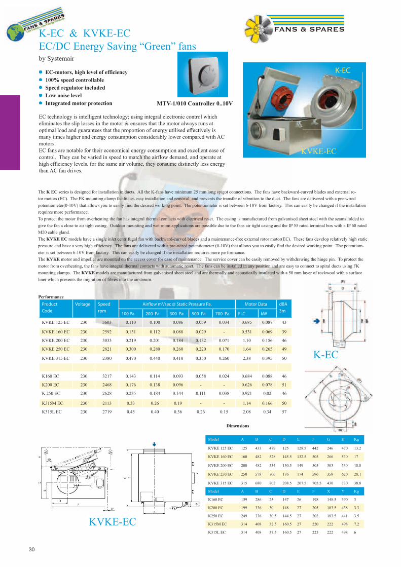
K-EC & KVKE-ECEC/DC Energy Saving “Green” fansby Systemair
• EC-motors, high level of efficiency• 100% speed controllable• Speed regulator included • Low noise level• Integrated motor protection
EC technology is intelligent technology; using integral electronic control which eliminates the slip losses in the motor & ensures that the motor always runs at optimal load and guarantees that the proportion of energy utilised effectively is many times higher and energy consumption considerably lower compared with AC motors.EC fans are notable for their economical energy consumption and excellent ease of control. They can be varied in speed to match the airflow demand, and operate at high efficiency levels. for the same air volume, they consume distinctly less energy than AC fan drives.
The K EC series is designed for installation in ducts. All the K-fans have minimum 25 mm long spigot connections. The fans have backward-curved blades and external ro-tor motors (EC). The FK mounting clamp facilitates easy installation and removal, and prevents the transfer of vibration to the duct. The fans are delivered with a pre-wired potentiometer(0-10V) that allows you to easily find the desired working point. The potentiometer is set between 6-10V from factory. This can easily be changed if the installation requires more performance.To protect the motor from overheating the fan has integral thermal contacts with electrical reset. The casing is manufactured from galvanised sheet steel with the seams folded to give the fan a close to air tight casing. Outdoor mounting and wet room applications are possible due to the fans air tight casing and the IP 55 rated terminal box with a IP 68 rated M20 cable gland.The KVKE EC models have a single inlet centrifugal fan with backward-curved blades and a maintenance-free external rotor motor(EC). These fans develop relatively high static pressure and have a very high efficiency. The fans are delivered with a pre-wired potentiometer (0-10V) that allows you to easily find the desired working point. The potentiom-eter is set between 6-10V from factory. This can easily be changed if the installation requires more performance.The KVKE motor and impeller are mounted on the access cover for ease of maintenance. The service cover can be easily removed by withdrawing the hinge pin. To protect the motor from overheating, the fans have integral thermal contacts with automatic reset. The fans can be installed in any position and are easy to connect to spiral ducts using FK mounting clamps. The KVKE models are manufactured from galvanised sheet steel and are thermally and acoustically insulated with a 50 mm layer of rockwool with a surface liner which prevents the migration of fibres into the airstream.
Product
Code
Voltage
Speed
rpm
Airfl ow m3/sec @ Static Pressure Pa. Motor Data dBA
3m100 Pa 200 Pa 300 Pa 500 Pa 700 Pa FLC kW
KVKE 125 EC 230 3603 0.110 0.100 0.086 0.059 0.034 0.685 0.087 43
KVKE 160 EC 230 2592 0.131 0.112 0.088 0.029 - 0.531 0.069 39
KVKE 200 EC 230 3033 0.219 0.201 0.184 0.132 0.071 1.10 0.156 46
KVKE 250 EC 230 2821 0.300 0.280 0.260 0.220 0.170 1.64 0.265 49
KVKE 315 EC 230 2380 0.470 0.440 0.410 0.350 0.260 2.38 0.395 50
K160 EC 230 3217 0.143 0.114 0.093 0.058 0.024 0.684 0.088 46
K200 EC 230 2468 0.176 0.138 0.096 - - 0.626 0.078 51
K 250 EC 230 2628 0.235 0.184 0.144 0.111 0.038 0.921 0.02 46
K315M EC 230 2113 0.33 0.26 0.19 - - 1.14 0.166 50
K315L EC 230 2719 0.45 0.40 0.36 0.26 0.15 2.08 0.34 57
Model A B C D E F G H Kg
KVKE 125 EC 125 433 479 125 128.5 442 246 470 13.2
KVKE 160 EC 160 482 528 145.5 132.5 505 266 530 17
KVKE 200 EC 200 482 534 150.5 149 505 303 530 18.8
KVKE 250 EC 250 578 700 176 174 596 359 620 28.1
KVKE 315 EC 315 680 802 208.5 207.5 705.5 430 730 38.8
Model A B C D E F X Y Kg
K160 EC 159 286 25 147 26 198 148.5 390 3
K200 EC 199 336 30 148 27 205 183.5 438 3.3
K250 EC 249 336 30.5 144.5 27 202 183.5 441 3.5
K315M EC 314 408 32.5 160.5 27 220 222 498 7.2
K315L EC 314 408 37.5 160.5 27 225 222 498 6
Dimensions
KVKE-EC
K-EC
K-EC
KVKE-EC
Performance
MTV-1/010 Controller 0..10V
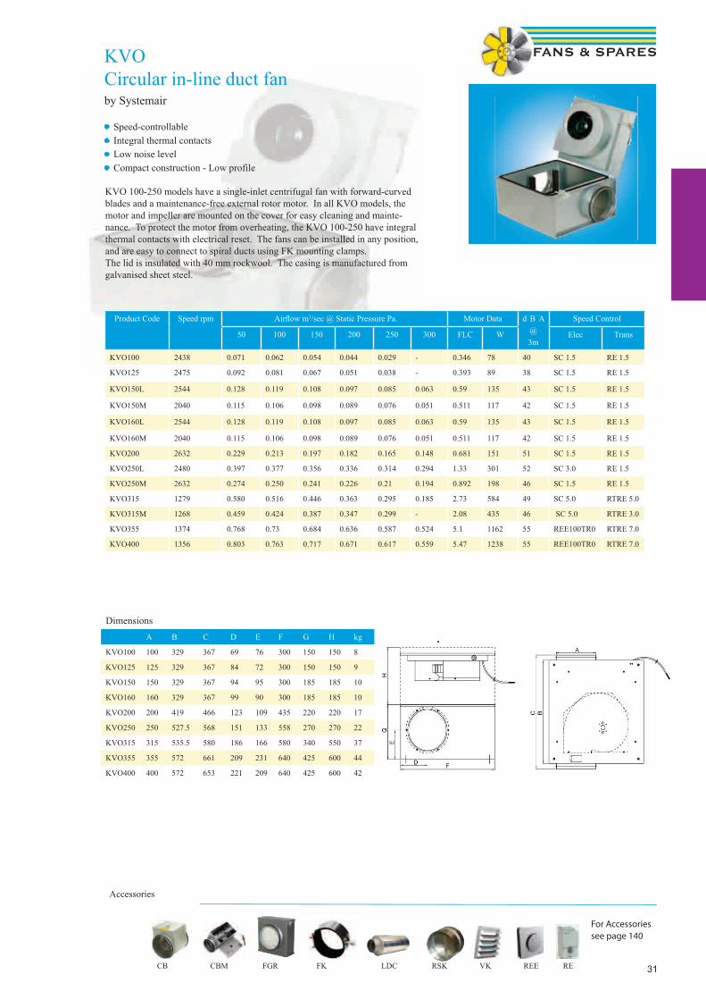
31
KVOCircular in-line duct fanby Systemair
Product Code Speed rpm Airfl ow m3/sec @ Static Pressure Pa. Motor Data d B A @3m
Speed Control
50 100 150 200 250 300 FLC W Elec Trans
KVO100 2438 0.071 0.062 0.054 0.044 0.029 - 0.346 78 40 SC 1.5 RE 1.5
KVO125 2475 0.092 0.081 0.067 0.051 0.038 - 0.393 89 38 SC 1.5 RE 1.5
KVO150L 2544 0.128 0.119 0.108 0.097 0.085 0.063 0.59 135 43 SC 1.5 RE 1.5
KVO150M 2040 0.115 0.106 0.098 0.089 0.076 0.051 0.511 117 42 SC 1.5 RE 1.5
KVO160L 2544 0.128 0.119 0.108 0.097 0.085 0.063 0.59 135 43 SC 1.5 RE 1.5
KVO160M 2040 0.115 0.106 0.098 0.089 0.076 0.051 0.511 117 42 SC 1.5 RE 1.5
KVO200 2632 0.229 0.213 0.197 0.182 0.165 0.148 0.681 151 51 SC 1.5 RE 1.5
KVO250L 2480 0.397 0.377 0.356 0.336 0.314 0.294 1.33 301 52 SC 3.0 RE 1.5
KVO250M 2632 0.274 0.250 0.241 0.226 0.21 0.194 0.892 198 46 SC 1.5 RE 1.5
KVO315 1279 0.580 0.516 0.446 0.363 0.295 0.185 2.73 584 49 SC 5.0 RTRE 5.0
KVO315M 1268 0.459 0.424 0.387 0.347 0.299 - 2.08 435 46 SC 5.0 RTRE 3.0
KVO355 1374 0.768 0.73 0.684 0.636 0.587 0.524 5.1 1162 55 REE100TR0 RTRE 7.0
KVO400 1356 0.803 0.763 0.717 0.671 0.617 0.559 5.47 1238 55 REE100TR0 RTRE 7.0
DimensionsA B C D E F G H kg
KVO100 100 329 367 69 76 300 150 150 8
KVO125 125 329 367 84 72 300 150 150 9
KVO150 150 329 367 94 95 300 185 185 10
KVO160 160 329 367 99 90 300 185 185 10
KVO200 200 419 466 123 109 435 220 220 17
KVO250 250 527.5 568 151 133 558 270 270 22
KVO315 315 535.5 580 186 166 580 340 550 37
KVO355 355 572 661 209 231 640 425 600 44
KVO400 400 572 653 221 209 640 425 600 42
Accessories
• Speed-controllable• Integral thermal contacts• Low noise level• Compact construction - Low profile
KVO 100-250 models have a single-inlet centrifugal fan with forward-curved blades and a maintenance-free external rotor motor. In all KVO models, the motor and impeller are mounted on the cover for easy cleaning and mainte-nance. To protect the motor from overheating, the KVO 100-250 have integral thermal contacts with electrical reset. The fans can be installed in any position, and are easy to connect to spiral ducts using FK mounting clamps.The lid is insulated with 40 mm rockwool. The casing is manufactured from galvanised sheet steel.
For Accessoriessee page 140
CB CBM FGR FK LDC RSK VK REE RE
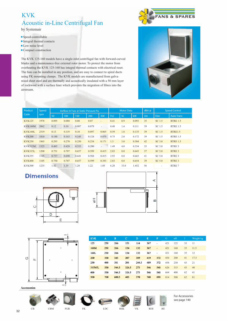
32
KVK FanAcoustic in-line centrifugal fan
Product
Code
Speed
rpm Airfl ow m3/sec @ Static Pressure Pa. Motor Data dBA @ Speed Control
50 100 150 200 300 FLC SC kW 3m Elec Auto Trans
KVK125 1978 0.095 0.088 0.08 0.07 - 0.41 0.9 0.093 35 SC 1.5 RTRE 1.5
KVK160M 2062 0.12 0.10 0.087 0.079 - 0.48 1.4 0.111 39 SC 1.5 RTRE 1.5
KVK160L 2519 0.13 0.119 0.10 0.097 0.065 0.59 1.8 0.135 39 SC 1.5 RTRE1.5
KVK200 1810 0.180 0.163 0.145 0.124 0.070 0.75 2.0 0.172 39 SC 1.5 RTRE 1.5
KVK250 1965 0.293 0.270 0.250 0.234 0.171 1.3 3.0 0.304 42 SC 3.0 RTRE 1.5
KVK315M 1325 0.485 0.428 0.353 0.200 - 1.49 4.0 0.334 35 SC 3.0 RTRE 3
KVK315L 1200 0.751 0.707 0.657 0.599 0.415 2.83 8.0 0.643 37 SC 5.0 RTRE 3
KVK355 1165 0.737 0.690 0.641 0.584 0.415 2.93 8.0 0.665 41 SC 5.0 RTRE 3
KVK400 1105 0.750 0.707 0.657 0.599 0.393 2.83 8.0 0.654 39 SC 5.0 RTRE 3
KVK500 1235 1.42 1.35 1.28 1.22 1.05 6.28 33.0 1.452 56 - RTRE 7
Accessories
KVK A B C D E F G øH I Weight kg
125 250 266 151 114 367 - 421 125 35 11
160M 250 266 134 132 367 - 421 160 35 11.5
160L 250 266 134 132 367 - 421 160 35 12
200 350 345 207 309 419 372 454 200 41 17.5
250 400 381 201 244.5 489 372 458 250 43 21
315M/L 550 544.5 326.5 273 546 540 626 315 43 40
400 550 544.5 326.5 273 546 540 664 400 62 41
500 700 680.5 403 370 740 690 814 500 62 81
For Accessoriessee page 140
by Systemair
• Speed-controllable• Integral thermal contacts• Low noise level• Compact construction
The KVK 125-160 models have a single-inlet centrifugal fan with forward-curved blades and a maintenance-free external rotor motor. To protect the motor from overheating the KVK 125-160 has integral thermal contacts with electrical reset. The fans can be installed in any position, and are easy to connect to spiral ducts using FK mounting clamps. The KVK models are manufactured from galva-nised sheet steel and are thermally and acoustically insulated with a 50 mm layer of rockwool with a surface liner which prevents the migration of fi bres into the airstream.
KVK Acoustic in-Line Centrifugal Fan
Accessories
KVK A B C D E F
125 250 266 151 114 367 -
160M 250 266 134 132 367 -
160L 250 266 134 132 367 -
200 350 345 207 309 419 372
250 400 381 201 244.5 489 372
315M/L 550 544.5 326.5 273 546 540
400 550 544.5 326.5 273 546 540
500 700 680.5 403 370 740 690
CB CBM FGR FK LDC RSK VK REE RE

33
KVK DUO Acoustic in-Line Twin Fan by Systemair
• Speed-controllable• Integral thermal contacts• Low noise level• Twin fan• Can be installed for bottom access
Product
Code
Speed
rpm
Airfl ow m3/sec @ Static Pressure Pa. Motor Data dBA @
3m
Speed control
50 100 150 200 250 300 FLC SC kW Elec Trans ACO Panel
KVK DUO125 1720 0.046 0.035 0.012 0.17 0.5 0.041 28 SC 1.5 RTRE 1.5 ACO 8A
KVK DUO160 2010 0.097 0.084 0.063 0.031 0.35 0.85 0.081 35 SC 1.5 RTRE 1.5 ACO 8A
KVK DUO200 1750 0.183 0.168 0.151 0.133 0.104 0.056 0.77 2.0 0.177 39 SC 1.5 RTRE 1.5 ACO 8A
KVK DUO250 1965 0.295 0.272 0.250 0.228 0.202 0.175 1.3 3.0 0.304 42 SC 3.0 RTRE 3.0 ACO 8A
KVK DUO315M 1325 0.495 0.435 0.350 0.201 1.49 4.0 0.334 35 SC 3.0 RTRE 3.0 ACO 8A
KVK DUO315L 1220 0.734 0.698 0.645 0.586 0.501 0.387 2.61 8.0 0.593 37 SC 5.0 RTRE 3.0 ACO 8A
KVK DUO355 1170 0.734 0.698 0.645 0.586 0.501 0.387 2.78 8.0 0.632 37 SC 5.0 RTRE 3.0 ACO 8A
KVK DUO400 1190 0.734 0.698 0.645 0.586 0.501 0.387 2.78 8.0 0.638 39 SC 5.0 RTRE 3.0 ACO 8A
Accessories
Dimensions KVK DUO
REF A B C D E F kg
125 514 351 337 125 300 35 19
160 514 351 337 160 300 35 22
200 604 401 390 200 350 39 32
250 724 501 461 250 400 41 36
315-400 952 567 510 315/355/400 550 41/64/65 72
For Accessoriessee page 140
KVK DUO models have double inlet centrifugal fans with forward-curved impellers and maintenance-free external rotor motors. To protect the motors from overheating the fans have integral thermal contacts with leads for connection to a motor protection device. The fans are easy to connect to spiral ducts using FK mounting clamps. The KVK DUO models are manufactured from galvanised sheet steel and are thermally and acoustically insulated with a 50 mm layer of mineral wool. Internal surfaces are protected with perforated galva-nised sheet steel.
CB CBM FGR FK LDC RSK VK REE RE
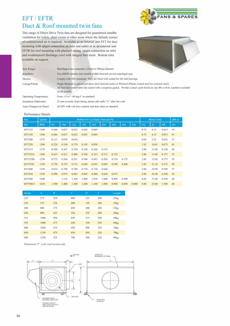
34
EFT / EFTRDuct & Roof mounted twin fansThis range of Direct Drive Twin fans are designed for guaranteed standby ventilation for toilets, plant rooms or other areas where the failsafe extract of contaminated air is required. Available as an Internal unit EFT for duct mounting with spigot connection on inlet and outlet or as an external unit EFTR for roof mounting with plastisol casing. spigot connection on inlet and weatherproof discharge cowl with integral bird mesh. Bottom inlet available on request.
Size Range:. Duct/Spigot size connection 125mm to 500mm diameter
Impellers: Two DIDW (double inlet double width) forward curved centrifugal type
Motors: Comply with ISO standards. They are fi tted with sealed for life ball bearings
Casing/Finish: Single Skinned in galvanised sheet steel (internal units) or Plastisol (Plastic coated steel for external units). All fans have removable lids sealed with a neoprene gasket. Powder coated paint fi nish (to any BS or RAL number) available on all models.
Operating Temperature: From -15 to + 40 deg C as standard.
Insulation (Optional): 25 mm acoustic foam lining. please add suffi x “L” after fan code
Auto Changeover Panel: ACOP1 with volt free contacts and duty share as standard
Performance DetailsFan Speed Airfl ow m3/s @ Static Pressure Pa Motor Data dBA @
Ref RPM 50 100 125 150 200 250 300 350 550 FLC SC kW 3m
EFT125 1340 0.460 0.037 0.032 0.025 0.005 0.75 4.13 0.015 39
EFT150 1340 0.046 0.037 0.032 0.025 0.005 0.75 4.13 0.015 41
EFT200 1375 0.113 0.070 0.036 0.64 3.52 0.022 37
EFT250 1360 0.228 0.190 0.170 0.145 0.050 1.82 10.01 0.073 43
EFT315 1370 0.398 0.367 0.350 0.320 0.268 0.153 2.00 11.00 0.150 50
EFT355A 1100 0.425 0.412 0.400 0.388 0.353 0.313 0.125 2.00 11.00 0.373 55
EFT355B 1250 0.575 0.560 0.551 0.540 0.491 0.450 0.376 0.175 2.85 15.68 0.373 55
EFT355C 1350 0.750 0.725 0.712 0.690 0.655 0.605 0.540 0.400 3.85 21.18 0.373 58
EFT400 1350 0.810 0.790 0.780 0.770 0.730 0.660 3.80 20.90 0.550 57
EFT450 1350 0.990 0.975 0.965 0.945 0.900 0.820 0.675 4.90 26.40 0.550 59
EFT500 1300 - 1.110 1.100 1.090 1.070 1.040 0.996 0.890 6.85 37.68 0.550 60
EFT500/3 1410 1.500 1.400 1.300 1.200 1.100 1.000 0.900 0.850 0.800 5.00 25.00 1.500 60
Model A B C D F weight
125 575 238 400 125 200 25kg
150 575 238 400 150 200 25kg
200 800 275 450 200 200 32kg
250 800 425 550 250 200 38kg
315 1000 450 650 315 200 44kg
355 1000 475 650 350 250 64kg
400 1050 475 650 400 250 70kg
450 1150 475 650 450 250 70kg
500 1250 525 700 500 250 98kg
Dimensiom“F” is for roof version only.

35
EFTB / EFTBRBelt driven twin fans This range of Belt Driven Twin fans are designed for guaranteed standby ventilation for toilets, plant rooms or other areas where the failsafe extract of contaminated air is required. Available as an Internal unit EFTB for duct mounting with 20mm “mez” fl ange connection on inlet and outlet or as an external unit EFTRB for roof mounting with plastisol casing. 20mm “mez” fl ange connection on inlet and weatherproof discharge cowl with integral bird mesh. Bottom inlet available on request.
Size Range: Four standard case sizes with different combinations of motors and pulleys giving an extensive range of fan duties.
Impellers: Two DIDW (double inlet double width) forward curved centrifugal type
Motors: Comply with BS5000 & IEC34-1. Foot mounted type TEFV IP55 Class F insulation. They are fi tted with sealed for life ball bearings
Casing/Finish: Double Skinned in galvanised sheet steel (internal units) or Plastisol single skinned (Plastic coated steel for external units). All fans have sealed removable access panels. Powder coated paint fi nish (to any BS or RAL number) available on all models.
Operating Temperature: . From -15 to + 40 deg C as standard
Insulation : (Optional) 25mm acoustic foam lining. please add suffi x “L” after fan code
Auto Changeover Panel: ACOP3/DS with volt free contacts and duty share as standard
Fan Airfl ow m3/s @ Static Pressure Pa Motor Data
Ref 50 100 150 200 250 300 350 400 450 500 FLC SC kW
EFTB 7/1 Airfl ow m3/s 0.790 0.750 0.700 0.650 0.600 2.00 11.00 0.75
dB(A) 79 78 76 75 74
EFTB 7/2 Airfl ow m3/s 0.95 0.9 0.85 0.8 0.75 0.7 2.90 16.00 1.10
dB(A) 79 78 77 76 76 75
EFTB 7/3 Airfl ow m3/s 1.0 0.95 0.9 0.85 0.8 2.90 16.00 1.10
dB(A) 80 79 78 77 77
EFTB 7/4 Airfl ow m3/s 1.0 0.9 0.8 0.7 3.90 21.50 1.50
dB(A) 80 79 77 76
EFTB 8/1 Airfl ow m3/s 1.07 1.02 0.95 0.9 2.00 11.00 0.75
dB(A) 77 76 75 74
EFTB 8/2 Airfl ow m3/s 1.21 1.15 1.1 1.05 1.0 2.90 16.00 1.10
dB(A) 80 79 78 77 77
EFTB 8/3 Airfl ow m3/s 1.25 1.2 1.15 1.1 1.05 3.90 21.50 1.50
dB(A) 81 80 79 79 78
EFTB 8/4 Airfl ow m3/s 1.3 1.25 1.2 1.15 1.1 5.30 29.20 2.20
dB(A) 82 81 80 80 80
EFTB 9/1 Airfl ow m3/s 1.42 1.33 1.28 1.21 2.90 16.00 1.10
dB(A) 80 78 78 77
EFTB 9/2 Airfl ow m3/s 1.7 1.65 1.6 1.55 1.5 3.90 21.50 1.50
dB(A) 79 79 78 78 78
EFTB 9/3 Airfl ow m3/s 1.85 1.8 1.75 1.7 1.65 5.30 29.20 2.20
dB(A) 81 81 81 80 80
EFTB 9/4 Airfl ow m3/s 2.0 1.95 1.9 1.85 1.8 7.10 39.10 3.00
dB(A) 83 82 82 82 82
EFTB 10/1 Airfl ow m3/s 2.14 2.09 2.0 1.9 1.8 3.90 21.50 1.50
dB(A) 80 79 79 78 78
EFTB 10/2 Airfl ow m3/s 2.4 2.35 2.3 2.25 2.16 2.05 5.30 29.20 2.20
dB(A) 82 82 82 81 81 80
EFTB 10/3 Airfl ow m3/s 2.52 2.47 2.42 2.37 2.32 2.28 7.10 39.10 3.00
dB(A) 83 83 83 83 83 83
EFTB 10/4 Airfl ow m3/s 2.53 2.4 2.35 2.3 2.2 7.10 39.10 3.00
dB(A) 84 83 83 83 82
Performance Details

36
Belt driven twin fans
Model A B C D E F Weight kg
7 1000 500 950 600 450 250 190
8 1150 550 1000 750 450 275 240
9 1200 650 1150 900 500 300 275
10 1450 700 1200 900 600 300 300
Run & Standby Axial Fans
• Run & Standby Axial fans for large air volumes, where back up is needed.• Sizes up to 1250mm Dia• Duties up to 20m3/s• Can be installed in any position• Idle losses taken into account• Auto Changeover panels with Duty Share available• Emergency Smoke Extract versions avail-able• For all selections, please enquire
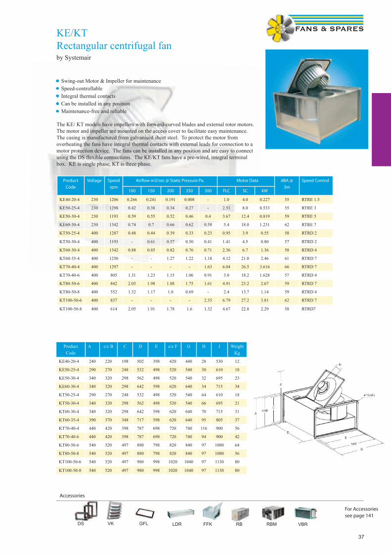
37
DS VK GFL LDR FFK RB RBM VBR
Accessories
For Accessoriessee page 141
KE/KTRectangular centrifugal fanby Systemair
• Swing-out Motor & Impeller for maintenance• Speed-controllable• Integral thermal contacts• Can be installed in any position• Maintenance-free and reliable
The KE/ KT models have impellers with forward-curved blades and external rotor motors. The motor and impeller are mounted on the access cover to facilitate easy maintenance. The casing is manufactured from galvanised sheet steel. To protect the motor from overheating the fans have integral thermal contacts with external leads for connection to a motor protection device. The fans can be installed in any position and are easy to connect using the DS flexible connections. The KE/KT fans have a pre-wired, integral terminal box. KE is single phase, KT is three phase.
Product
Code
Voltage Speed
rpm
Airfl ow m3/sec @ Static Pressure Pa. Motor Data dBA @
3m
Speed Control
100 150 200 250 300 FLC SC kW
KE40-20-4 230 1206 0.266 0.241 0.191 0.008 - 1.0 4.0 0.227 55 RTRE 1.5
KE50-25-4 230 1298 0.42 0.38 0.34 0.27 - 2.51 8.0 0.533 55 RTRE 3
KE50-30-4 230 1193 0.59 0.55 0.52 0.46 0.4 3.67 12.4 0.819 59 RTRE 5
KE60-30-4 230 1342 0.74 0.7 0.66 0.62 0.58 5.4 18.0 1.231 62 RTRE 7
KT50-25-4 400 1287 0.48 0.44 0.39 0.33 0.23 0.95 3.9 0.55 58 RTRD 2
KT50-30-4 400 1193 - 0.61 0.57 0.50 0.41 1.41 4.5 0.80 57 RTRD 2
KT60-30-4 400 1342 0.88 0.85 0.82 0.76 0.71 2.36 6.7 1.36 58 RTRD 4
KT60-35-4 400 1250 - - 1.27 1.22 1.18 4.12 21.0 2.46 61 RTRD 7
KT70-40-4 400 1297 - - - - 1.63 6.04 26.5 3.616 66 RTRD 7
KT70-40-6 400 805 1.31 1.23 1.15 1.06 0.91 3.0 18.2 1.628 57 RTRD 4
KT80-50-6 400 842 2.03 1.98 1.88 1.75 1.61 4.91 23.2 2.67 59 RTRD 7
KT80-50-8 400 552 1.32 1.17 1.0 0.69 - 2.4 13.7 1.14 59 RTRD 4
KT100-50-6 400 837 - - - - 2.35 6.79 27.2 3.81 62 RTRD 7
KT100-50-8 400 614 2.05 1.91 1.78 1.6 1.32 4.67 22.8 2.29 58 RTRD7
ProductCode
A c/c B C D E c/c F G H J WeightKg
KE40-20-4 240 220 198 502 398 420 440 28 530 12
KE50-25-4 290 270 248 532 498 520 540 30 610 18
KE50-30-4 340 320 298 562 498 520 540 32 695 23
KE60-30-4 340 320 298 642 598 620 640 34 715 34
KT50-25-4 290 270 248 532 498 520 540 64 610 18
KT50-30-4 340 320 298 562 498 520 540 66 695 21
KT60-30-4 340 320 298 642 598 620 640 70 715 31
KT60-35-4 390 370 348 717 598 620 640 95 805 37
KT70-40-4 440 420 398 787 698 720 740 116 900 56
KT70-40-6 440 420 398 787 698 720 740 94 900 42
KT80-50-6 540 520 497 880 798 820 840 97 1080 64
KT80-50-8 540 520 497 880 798 820 840 97 1080 56
KT100-50-6 540 520 497 980 998 1020 1040 97 1130 80
KT100-50-8 540 520 497 980 998 1020 1040 97 1130 80
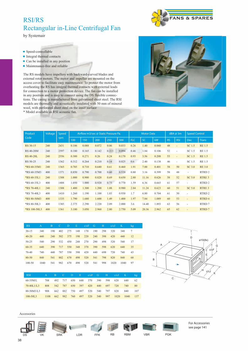
38
RSI/RSRectangular in-Line Centrifugal Fanby Systemair
RSI A B C D E c/cF G H c/cJ K kg
60-35M/L 708 492 717 650 648 370 390 598 620 640 62
70-40L1/L3 808 542 787 650 397 420 440 697 720 740 80
80-50M3/L3 908 662 882 750 497 520 540 797 820 840 107
100-50L3 1108 662 982 760 497 520 540 997 1020 1040 137
C
A
B
D
E
c/cFG
H c/cJK
ø10(8x)
DS VK SRK LDR FFK RB RBM VBR PGK
Accessories
For Accessoriessee page 141
Product
Code
Voltage Speed
rpm
Airfl ow m3/sec @ Static Pressure Pa. Motor Data dBA @ 3m Speed Control
100 150 200 250 300 FLC SC kW RS RSI Elec Trans
RS 30-15 240 2431 0.106 0.088 0.072 0.06 0.033 0.26 1.40 0.060 48 - SC 1.5 RE 1.5
RS 40-20M 240 2597 0.180 0.165 0.142 0.113 0.094 0.46 1.84 0.106 52 - SC 1.5 RE 1.5
RS 40-20L 240 2556 0.300 0.271 0.26 0.24 0.170 0.93 3.56 0.208 53 - SC 1.5 RE 1.5
RS 50-25 240 1362 0.312 0.264 0.210 0.14 0.025 0.6 2.40 0.138 46 - SC 1.5 RE 1.5
*RS 60-35M1 240 1365 0.785 0.710 0.640 0.61 0.460 1.91 7.00 0.401 58 50 SC 3.0 RE 3.0
*RS 60-35M3 400 1371 0.850 0.790 0.700 0.60 0.520 0.80 3.16 0.399 58 48 - RTRD 2
*RS 60-35L1 240 1308 1.000 0.900 0.820 0.69 0.650 2.80 11.16 0.626 58 52 SC 5.0 RTRE 3
*RS 60-35L3 400 1408 1.050 1.000 0.920 0.75 0.770 1.59 6.36 0.665 61 57 - RTRD 2
*RS 70-40L1 240 1308 1.400 1.300 1.200 1.08 0.980 2.84 11.24 0.623 60 51 SC 5.0 RTRE 3
*RS 70-40L3 400 1410 1.260 1.190 1.100 1.03 0.930 1.7 6.80 0.704 61 50 - RTRD 2
*RS 80-50M3 400 1335 1.790 1.680 1.600 1.49 1.400 1.97 7.84 1.089 60 53 - RTRD 4
*RS 80-50L3 400 1385 2.375 2.290 2.220 2.09 2.000 3.6 14.40 1.893 63 56 - RTRD 7
*RS 100-50L3 400 1361 3.180 3.050 2.960 2.80 2.750 5.09 20.36 2.962 65 62 - RTRD 7
• Speed-controllable• Integral thermal contacts• Can be installed in any position• Maintenance-free and reliable
The RS models have impellers with backward-curved blades and external rotor motors. The motor and impeller are mounted on the access cover to facilitate easy maintenance. To protect the motor from overheating the RS has integral thermal contacts with external leads for connection to a motor protection device. The fan can be installed in any position and is easy to connect using the DS flexible connec-tions. The casing is manufactured from galvanised sheet steel. The RSI models are thermally and acoustically insulated with 50 mm of mineral wool, with perforated sheet steel on the inner surface* Model available as RSI acoustic fan.
RS A B C D E c/cF G H c/cJ K kg
30-15 340 190 402 275 148 170 190 298 320 340 7
40-20 440 240 502 375 198 220 240 398 420 440 12
50-25 540 290 532 450 248 270 290 498 520 540 17
60-35 640 390 717 550 348 370 390 598 620 640 35
70-40 740 440 787 550 398 420 440 698 720 740 43
80-50 840 541 882 670 498 520 541 798 820 840 68
100-50 1040 541 982 670 498 520 541 998 1020 1040 97
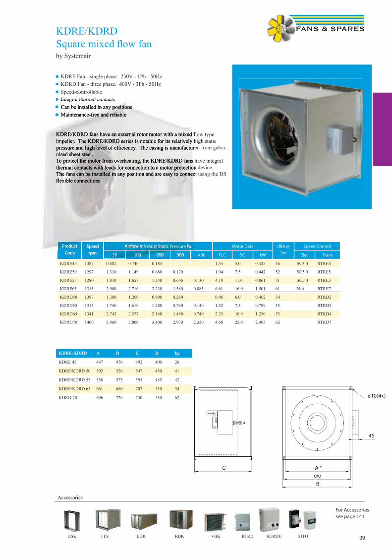
39
KDRE/KDRDSquare mixed fl ow fan by Systemair
• KDRE Fan - single phase. 230V - 1Ph - 50Hz• KDRD Fan - three phase. 400V - 3Ph - 50Hz
Product
Code
Speed
rpm
Airfl ow m3/sec @ Static Pressure Pa. Motor Data dBA @
3m
Speed Control
50 100 200 300 400 FLC SC kW Elec Trans
KDRE45 1387 0.882 0.740 0.185 1.55 5.0 0.325 46 SC3.0 RTRE3
KDRE50 1297 1.310 1.149 0.680 0.120 1.94 7.5 0.442 52 SC5.0 RTRE5
KDRE55 1280 1.810 1.657 1.240 0.666 0.130 4.10 11.0 0.861 51 SC5.0 RTRE5
KDRE65 1315 2.900 2.710 2.230 1.580 0.885 6.61 16.0 1.501 61 N/A RTRE7
KDRD50 1397 1.380 1.260 0.890 0.260 0.96 6.0 0.462 54 RTRD2
KDRD55 1315 1.746 1.610 1.280 0.760 0.140 1.52 7.5 0.789 55 RTRD2
KDRD65 1341 2.743 2.577 2.140 1.480 0.740 2.23 10.0 1.250 53 RTRD4
KDRD70 1400 3.960 3.800 3.400 2.930 2.320 4.68 25.0 2.493 62 RTRD7
KDRE/KDRD A B C D kg
KDRE 45 447 470 492 400 26
KDRE/KDRD 50 502 520 547 450 41
KDRE/KDRD 55 550 573 595 485 42
KDRE/KDRD 65 661 680 707 510 54
KDRD 70 696 720 740 530 62
Accessories
For Accessoriessee page 141
• Speed-controllable• Integral thermal contacts• Can be installed in any positions• Maintenance-free and reliable
KDRE/KDRD fans have an external rotor motor with a mixed flow type impeller. The KDRE/KDRD series is notable for its relatively high static pressure and high level of efficiency. The casing is manufactured from galva-nised sheet steel. To protect the motor from overheating, the KDRE/KDRD fans have integral thermal contacts with leads for connection to a motor protection device. The fans can be installed in any position and are easy to connect using the DS flexible connections.
Product
Code
Speed
rpm
Airfl ow m3/sec @ Static Pressure Pa.
50 100 200 300
• • Integral thermal contacts• • Can be installed in any positions•• Maintenance-free and reliable Maintenance-free and reliable
KDRE/KDRD fans have an external rotor motor with a mixed flow type impeller. The KDRE/KDRD series is notable for its relatively high static pressure and high level of efficiency. The casing is manufactured from galva-nised sheet steel. To protect the motor from overheating, the KDRE/KDRD fans have integral thermal contacts with leads for connection to a motor protection device. The fans can be installed in any position and are easy to connect using the DS flexible connections.
DSK FFS LDK RBK VBK RTRD RTRDU STDT

40
Multiflow SMB Square cased mixed flow fanby Elta
• Unique adjustable pitch mixed flow impeller.
• 9 standard case sizes from 350mm to 1000mm.
• Air volume flow rates of up to 7.88 m3/sec.
• Static pressures of up to 600 Pa.
• Wide operating range.
• Greater pressure capability than axial fans.
• Greater airflow capability than centrifugal fans.
• Non overloading power curve.
• Non-stall characteristic.
• Suitable for operating temperatures of up to 50° C.
• Motors are foot mounted totally enclosed metric type.
• Sealed for life ball bearings to operate at any angle.
• Motors weatherproofed to IP55 with Class ‘F’ insulation to EN 60034-5.
Multiflow SMB is a range of square cased mixed flow fans with a unique adjustable pitch mixed flow
impeller, ideally suited for installation within ductwork and suitable for extract or supply for a broad
range of industrial, commercial and residential applications.
Type A B C D E kg
SMB350 350 400 420 9 375 22
SMB400 400 450 480 9 425 30
SMB450 450 500 470 9 475 26
SMB500 500 550 500 9 525 30
SMB550 550 620 550 11 585 44
SMB650 650 720 600 11 685 58
SMB700 700 770 650 11 735 63
SMB800 800 870 700 11 835 79
SMB1000 1000 1070 800 11 1035 118
Product
Code
Voltage Speed
rpm
Airflow m3/sec @ Static Pressure Pa. Motor Data dBA @
4m
Speed control
Trans or Inv50 100 200 300 400 FLC SC kW
SMB350/4-5-2 230 1300 0.28 0.14 - - - 1.09 2.30 0.12 43 TC12
SMB350/2-4-2 230 2750 0.63 0.60 9.54 0.46 0.36 2.55 7.00 0.37 60 TC14
SMB400/4-5-2 230 1300 0.64 0.53 0.12 - - 1.51 3.69 0.18 50 TC12
SMB400/2-3-2 230 2750 1.16 1.14 1.07 1.00 0.90 6.15 22.7 1.0 68 TC112
SMB450/4-5-2 230 1350 1.09 0.97 0.57 0.10 - 2.56 5.93 0.37 54 TC14
SMB500/4-4-2 230 1350 1.48 1.36 1.08 0.60 0.05 3.70 11.9 0.55 58 TC18
SMB550/4-4-2 230 1350 2.30 2.15 1.76 1.25 0.38 6.28 16.4 1.0 62 TC110
SMB650/4-4-2 230 1350 2.81 2.72 2.46 2.11 1.60 10.1 25.9 1.5 68 TC112
SMB500/4-5-3 400 1410 1.73 1.60 1.32 0.87 - 2.0 11.4 0.75 58 TC33
SMB550/4-5-3 400 1410 2.43 2.33 2.03 1.60 0.84 2.90 15.4 1.1 62 TC33
SMB650/4-4-3 400 1420 2.97 2.84 2.59 2.29 1.85 3.70 20.4 1.5 67 EVFD/150
SMB700/6-4-3 400 920 2.65 2.38 1.73 0.65 - 2.12 8.70 0.75 59 TC35
SMB700/4-5-3 400 1415 4.51 4.40 4.10 3.73 3.34 6.78 47.5 3.0 68 EVFD/300
SMB800/8-5-3 400 700 3.26 2.92 1.42 - - 2.33 10.7 0.75 58 EVFD/150
SMB800/6-4-3 400 940 4.17 3.98 3.47 2.64 0.87 4.30 22.3 1.5 64 EVFD/220
SMB1000/8-4-3 400 710 6.53 6.20 5.35 3.98 0.93 5.31 32.9 2.2 61 EVFD/220
SMB1000/6-3-3 400 940 7.68 7.46 6.99 6.43 5.74 8.95 47.5 4.0 67 EVFD/400
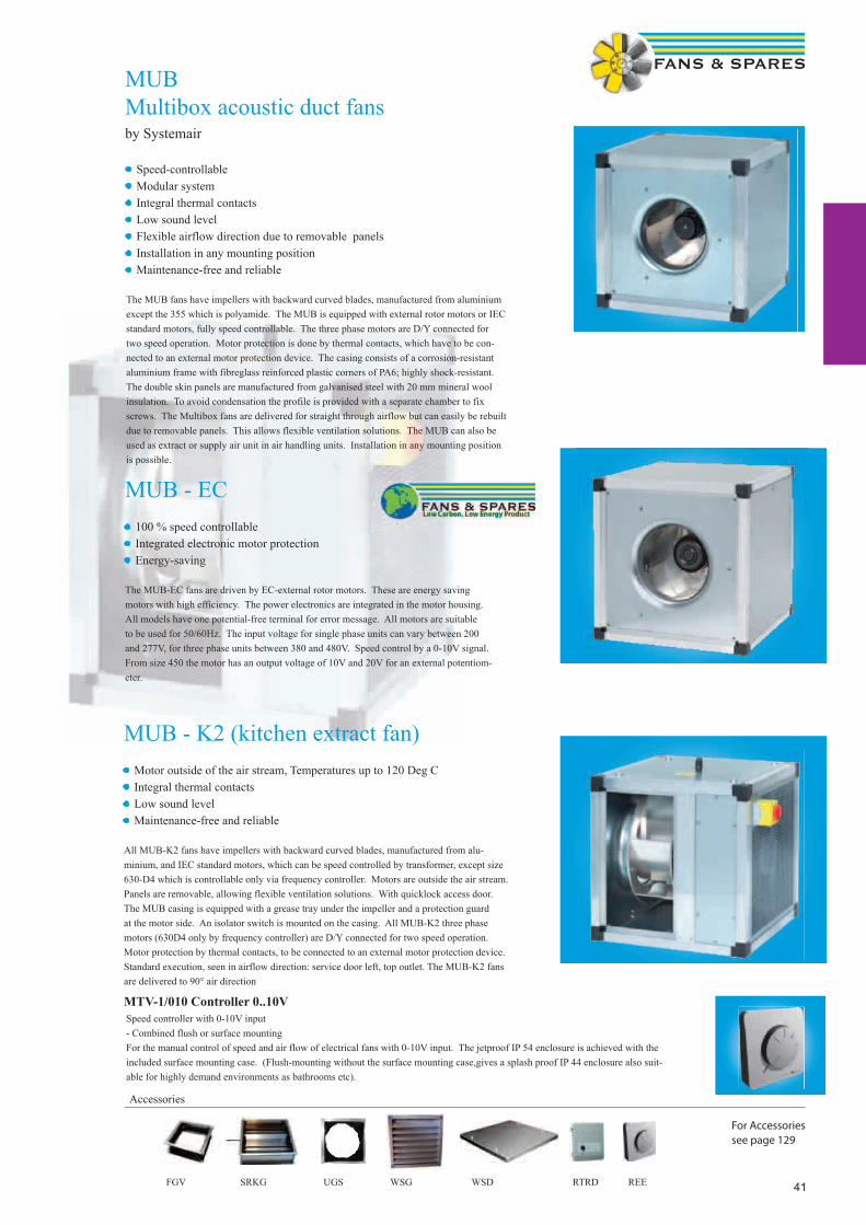
41
MUBMultibox acoustic duct fansby Systemair
Accessories
For Accessoriessee page 129
• Speed-controllable• Modular system• Integral thermal contacts• Low sound level• Flexible airflow direction due to removable panels • Installation in any mounting position• Maintenance-free and reliable
The MUB fans have impellers with backward curved blades, manufactured from aluminium except the 355 which is polyamide. The MUB is equipped with external rotor motors or IEC standard motors, fully speed controllable. The three phase motors are D/Y connected for two speed operation. Motor protection is done by thermal contacts, which have to be con-nected to an external motor protection device. The casing consists of a corrosion-resistant aluminium frame with fibreglass reinforced plastic corners of PA6; highly shock-resistant. The double skin panels are manufactured from galvanised steel with 20 mm mineral wool insulation. To avoid condensation the profile is provided with a separate chamber to fix screws. The Multibox fans are delivered for straight through airflow but can easily be rebuilt due to removable panels. This allows flexible ventilation solutions. The MUB can also be used as extract or supply air unit in air handling units. Installation in any mounting position is possible.
MUB - EC• 100 % speed controllable• Integrated electronic motor protection• Energy-saving
The MUB-EC fans are driven by EC-external rotor motors. These are energy saving motors with high efficiency. The power electronics are integrated in the motor housing. All models have one potential-free terminal for error message. All motors are suitable to be used for 50/60Hz. The input voltage for single phase units can vary between 200 and 277V, for three phase units between 380 and 480V. Speed control by a 0-10V signal. From size 450 the motor has an output voltage of 10V and 20V for an external potentiom-eter.
MUB - K2 (kitchen extract fan)• Motor outside of the air stream, Temperatures up to 120 Deg C• Integral thermal contacts• Low sound level• Maintenance-free and reliable
All MUB-K2 fans have impellers with backward curved blades, manufactured from alu-minium, and IEC standard motors, which can be speed controlled by transformer, except size 630-D4 which is controllable only via frequency controller. Motors are outside the air stream. Panels are removable, allowing flexible ventilation solutions. With quicklock access door. The MUB casing is equipped with a grease tray under the impeller and a protection guard at the motor side. An isolator switch is mounted on the casing. All MUB-K2 three phase motors (630D4 only by frequency controller) are D/Y connected for two speed operation. Motor protection by thermal contacts, to be connected to an external motor protection device. Standard execution, seen in airflow direction: service door left, top outlet. The MUB-K2 fans are delivered to 90° air direction
Speed controller with 0-10V input- Combined flush or surface mountingFor the manual control of speed and air flow of electrical fans with 0-10V input. The jetproof IP 54 enclosure is achieved with the included surface mounting case. (Flush-mounting without the surface mounting case,gives a splash proof IP 44 enclosure also suit-able for highly demand environments as bathrooms etc).
MTV-1/010 Controller 0..10V
FGV SRKG UGS WSG WSD RTRD REE

42
Product Code Airfl ow-
Straight
Speed
RPM
Airfl ow m3/sec @ Static Pressure Pa. Motor Data dBA
@
3m
Speed Control
Airfl ow 90º100 200 300 400 500 FLC kW Elec Trans
Single Phase Standard
MUB 025 355E4-A2 Straight 1260 0.551 0.43 0.096 - - 1.05 0.25 55 SC 1.5 RTRE 1.5
90º 0.636 0.50 0.288
MUB 042 400E4-A2 Straight 1360 0.96 0.85 0.65 0.20 - 2.2 0.373 49 SC 3.0 RTRE 3
90º 0.89 0.77 0.62 0.35
MUB 042 450E4-A2 Straight 1280 1.236 1.05 0.852 0.56 - 2.8 0.640 52 SC 5.0 RTRE 5
90º 1.317 1.10 0.912 0.67 -
MUB 042 499E4-A2 Straight 1320 1.50 1.306 1.09 0.85 0.482 4.95 1.10 48 N/A RTRE 5
90º 1.653 1.446 1.235 1.04 0.712
MUB 042 500E4-A2 Straight 1340 1.73 1.57 1.38 1.16 0.83 4.80 1.080 56 REE100TR0 RTRE 7
90º 1.958 1.748 1.54 1.32 1.107
Kitchen Version Single Phase
MUB 042 400E4-K2 90º 1370 0.97 0.83 0.64 0.35 5.1 0.75 49 N/A RTRE 7
MUB 042 450E4-K2 90º 1430 1.52 1.37 0.98 0.69 0.56 5.3 0.75 52 N/A RTRE 7
Three Phase Standard
MUB 025 355DV-A2 Straight 1300 0.524 0.386 0.262 - - 0.58 0.207 55 RTRD2
90º 0.606 0.469 0.378 0.10 -
MUB 042 400DV-A2 Straight 1340 0.906 0.771 0.59 0.09 - 0.7 0.305 49 RTRD2
90º 1.01 0.84 0.605 0.125 -
MUB 042 450DV-A2 Straight 1230 1.246 1.085 0.893 0.595 0.059 1.3 0.69 52 RTRD2
90º 1.375 1.178 0.973 0.753 0.184
MUB 042 499DV-A2 Straight 1200 1.408 1.216 0.998 0.694 0.199 1.8 0.9 48 RTRD2
90º 1.548 1.316 1.084 0.812 0.453
MUB 042 500DV-A2 Straight 1330 1.843 1.686 1.529 1.329 1.054 4.3 1.5* 56 RTRD7
90º 1.983 1.779 1.585 1.415 1.219
MUB 062 560DV-A2 Straight 1420 2.763 2.571 2.38 2.197 2.02 5.8 2.2* 57 RTRD7
90º 3.048 2.8 2.51 2.28 2.048
MUB 062 630DV-B2 Straight 1340 3.514 3.341 3.172 2.987 2.776 9.2 3.42 69 RTRD14
90º 3.958 3.764 3.563 3.368 3.177
MUB 062 630D4-A2 Straight 1400 3.781 3.632 3.48 3.312 3.129 9.5 4.0* 69 Inverter
90º 4.316 4.137 3.961 3.772 3.584
MUB 100 630D4-L Straight 1435 5.420 5.246 5.000 4.827 4.598 9.5 5.5 75 Inverter
MUB 100 710D6-A2 Straight 954 4.136 3.776 3.413 3.055 3.000 5.16 2.46 60 RTRD7
Kitchen Version Three Phase
MUB 042 400DV-K2 90º 1340 0.945 0.804 0.619 0.209 - 1.4 0.37 49 RTRD2
MUB 042 450DV-K2 90º 1230 1.372 1.163 0.965 0.749 - 2.5 0.75 52 RTRD4
MUB 042 500DV-K2 90º 1330 1.977 1.785 1.582 1.421 1.226 4.3 1.5 56 RTRD7
MUB 062 560DV-K2 90º 1400 3.037 2.808 2.529 2.265 2.046 5.8 2.2 57 RTRD7
MUB 062 630D4-K2 90º 1400 4.35 4.191 3.992 3.774 3.544 9.5 4.0 69 Inverter
EC Version Single Phase
MUB 025 315EC-A2 Straight 1870 0.49 0.37 0.25 0.12 - 1.4 0.18 44 MTV-1/010
MUB 025 355EC-A2 Straight 1660 0.77 0.69 0.58 0.47 0.24 2.7 0.43 48 MTV-1/010
MUB 042 400EC-A2 Straight 1339 0.92 0.78 0.62 0.39 - 2.26 0.378 48 MTV-1/010
MUB 042 450EC-A2-K Straight 1250 1.26 1.14 0.97 0.78 - 2.4 0.58 52 MTV-1/010
EC Version Three Phase
MUB 042 450EC-A2 Straight 1560 1.74 1.53 1.42 1.32 1.11 1.95 1.17 56 MTV-1/010
MUB 042 500EC-A2 Straight 1340 1.78 1.66 1.46 1.25 1.07 2.18 1.1 56 MTV-1/010
MUB 062 560EC-A2 Straight 1360 2.78 2.63 2.39 2.17 1.95 3.1 2.0 57 MTV-1/010
MUB 062 630EC-A2 Straight 1210 3.5 3.2 2.9 2.7 2.5 3.9 2.56 67 MTV-1/010
* Power @ shaft
MUB, MUB-EC, MUB-KTechnical Data
0.37
2.5 0.75
1.421 1.226 4.3 1.5
2.808 2.529 2.265 2.046 5.8 2.2
4.35 4.191 3.992 3.774 3.544 9.5 4.0
1870 0.49 0.37 0.25 0.12 - 1.4 0.18 44
1660 0.77 0.69 0.58 0.47 0.24 2.7 0.43 48
1339 0.92 0.78 0.62 0.39 - 2.26 0.378 48
1250 1.26 1.14 0.97 0.78 - 2.4 0.58 52
1560 1.74 1.53 1.42 1.32 1.11 1.95 1.17 56
1340 1.78 1.66 1.46 1.25 1.07 2.18 1.1 56
1360 2.78 2.63 2.39 2.17 1.95 3.1
1210 3.5 3.2 2.9 2.7 2.5
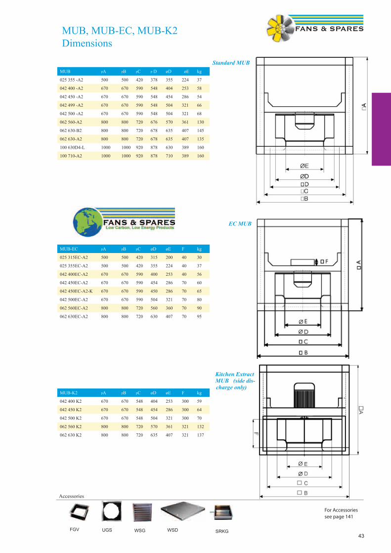
43FGV
Accessories
UGS WSG WSD SRKG
For Accessoriessee page 141
MUB pA pB pC p D øD øE kg
025 355 -A2 500 500 420 378 355 224 37
042 400 -A2 670 670 590 548 404 253 58
042 450 -A2 670 670 590 548 454 286 54
042 499 -A2 670 670 590 548 504 321 66
042 500 -A2 670 670 590 548 504 321 68
062 560-A2 800 800 720 676 570 361 130
062 630-B2 800 800 720 678 635 407 145
062 630-A2 800 800 720 678 635 407 135
100 630D4-L 1000 1000 920 878 630 389 160
100 710-A2 1000 1000 920 878 710 389 160
MUB-EC pA pB pC øD øE F kg
025 315EC-A2 500 500 420 315 200 40 30
025 355EC-A2 500 500 420 355 224 40 37
042 400EC-A2 670 670 590 400 253 40 56
042 450EC-A2 670 670 590 454 286 70 60
042 450EC-A2-K 670 670 590 450 286 70 65
042 500EC-A2 670 670 590 504 321 70 80
062 560EC-A2 800 800 720 560 360 70 90
062 630EC-A2 800 800 720 630 407 70 95
MUB
MUB-K2 pA pB pC øD øE F kg
042 400 K2 670 670 548 404 253 300 59
042 450 K2 670 670 548 454 286 300 64
042 500 K2 670 670 548 504 321 300 70
062 560 K2 800 800 720 570 361 321 132
062 630 K2 800 800 720 635 407 321 137
MUB, MUB-EC, MUB-K2Dimensions
Standard MUB
EC MUB
Kitchen Extract MUB (side dis-charge only)
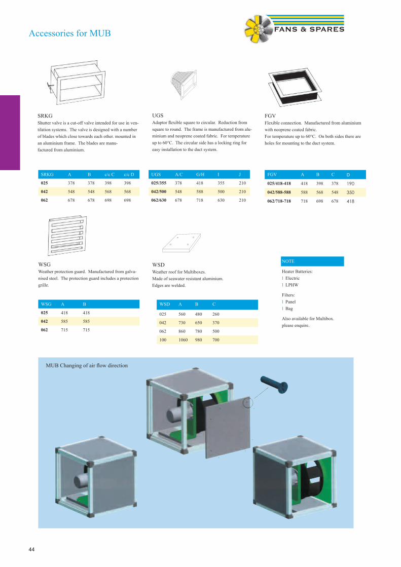
44
Accessories for MUB
UGSAdaptor flexible square to circular. Reduction from square to round. The frame is manufactured from alu-minium and neoprene coated fabric. For temperature up to 60°C. The circular side has a locking ring for easy installation to the duct system.
FGVFlexible connection. Manufactured from aluminium with neoprene coated fabric. For temperature up to 60°C. On both sides there are holes for mounting to the duct system.
WSGWeather protection guard. Manufactured from galva-nised steel. The protection guard includes a protection grille.
WSDWeather roof for Multiboxes. Made of seawater resistant aluminium. Edges are welded.
SRKGShutter valve is a cut-off valve intended for use in ven-tilation systems. The valve is designed with a number of blades which close towards each other. mounted in an aluminium frame. The blades are manu- factured from aluminium.
SRKG A B c/c C c/c D
025 378 378 398 398
042 548 548 568 568
062 678 678 698 698
UGS A/C G/H I J
025/355 378 418 355 210
042/500 548 588 500 210
062/630 678 718 630 210
FGV A B C D
025/418-418 418 398 378 190
042/588-588 588 568 548 350
062/718-718 718 698 678 418
WSG A B
025 418 418
042 585 585
062 715 715
WSD A B C
025 560 480 260
042 730 650 370
062 860 780 500
100 1060 980 700
MUB Changing of air flow direction
NOTE
Heater Batteries:l Electricl LPHW
Filters:l Panell Bag
Also available for Multibox.please enquire.
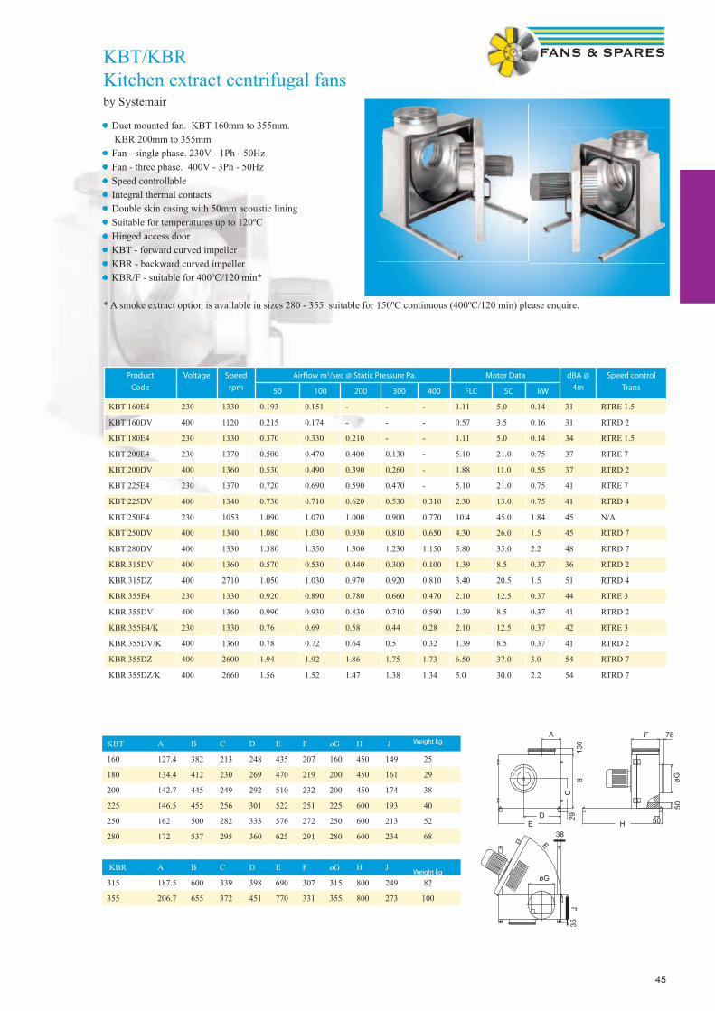
45
KBT/KBRKitchen extract centrifugal fansby Systemair
• Duct mounted fan. KBT 160mm to 355mm. KBR 200mm to 355mm • Fan - single phase. 230V - 1Ph - 50Hz• Fan - three phase. 400V - 3Ph - 50Hz • Speed controllable• Integral thermal contacts• Double skin casing with 50mm acoustic lining• Suitable for temperatures up to 120ºC• Hinged access door• KBT - forward curved impeller• KBR - backward curved impeller• KBR/F - suitable for 400ºC/120 min*
* A smoke extract option is available in sizes 280 - 355. suitable for 150ºC continuous (400ºC/120 min) please enquire.
Product
Code
Voltage Speed
rpm
Airfl ow m3/sec @ Static Pressure Pa. Motor Data dBA @
4m
Speed control
Trans50 100 200 300 400 FLC SC kW
KBT 160E4 230 1330 0.193 0.151 - - - 1.11 5.0 0.14 31 RTRE 1.5
KBT 160DV 400 1120 0.215 0.174 - - - 0.57 3.5 0.16 31 RTRD 2
KBT 180E4 230 1330 0.370 0.330 0.210 - - 1.11 5.0 0.14 34 RTRE 1.5
KBT 200E4 230 1370 0.500 0.470 0.400 0.130 - 5.10 21.0 0.75 37 RTRE 7
KBT 200DV 400 1360 0.530 0.490 0.390 0.260 - 1.88 11.0 0.55 37 RTRD 2
KBT 225E4 230 1370 0.720 0.690 0.590 0.470 - 5.10 21.0 0.75 41 RTRE 7
KBT 225DV 400 1340 0.730 0.710 0.620 0.530 0.310 2.30 13.0 0.75 41 RTRD 4
KBT 250E4 230 1053 1.090 1.070 1.000 0.900 0.770 10.4 45.0 1.84 45 N/A
KBT 250DV 400 1340 1.080 1.030 0.930 0.810 0.650 4.30 26.0 1.5 45 RTRD 7
KBT 280DV 400 1330 1.380 1.350 1.300 1.230 1.150 5.80 35.0 2.2 48 RTRD 7
KBR 315DV 400 1360 0.570 0.530 0.440 0.300 0.100 1.39 8.5 0.37 36 RTRD 2
KBR 315DZ 400 2710 1.050 1.030 0.970 0.920 0.810 3.40 20.5 1.5 51 RTRD 4
KBR 355E4 230 1330 0.920 0.890 0.780 0.660 0.470 2.10 12.5 0.37 44 RTRE 3
KBR 355DV 400 1360 0.990 0.930 0.830 0.710 0.590 1.39 8.5 0.37 41 RTRD 2
KBR 355E4/K 230 1330 0.76 0.69 0.58 0.44 0.28 2.10 12.5 0.37 42 RTRE 3
KBR 355DV/K 400 1360 0.78 0.72 0.64 0.5 0.32 1.39 8.5 0.37 41 RTRD 2
KBR 355DZ 400 2600 1.94 1.92 1.86 1.75 1.73 6.50 37.0 3.0 54 RTRD 7
KBR 355DZ/K 400 2660 1.56 1.52 1.47 1.38 1.34 5.0 30.0 2.2 54 RTRD 7
KBT A B C D E F øG H J
160 127.4 382 213 248 435 207 160 450 149 25
180 134.4 412 230 269 470 219 200 450 161 29
200 142.7 445 249 292 510 232 200 450 174 38
225 146.5 455 256 301 522 251 225 600 193 40
250 162 500 282 333 576 272 250 600 213 52
280 172 537 295 360 625 291 280 600 234 68
KBR A B C D E F øG H J
315 187.5 600 339 398 690 307 315 800 249 82
355 206.7 655 372 451 770 331 355 800 273 100
Weight kg
Weight kg

46
ZAP/ZSP/AWPlate mounted axial fansby Ziehl Abegg
• Sickle & aerofoil bladed fans. 200 mm to 710 mm• Fan - single phase. 230 V. 1 Ph. 50 Hz• Die cast aluminium impellers• (AW type pressed steel blades)• Insulation class ‘F’ IP54 (AW type IP44)• Operating range -40ºC to 70ºC• Thermal protection ‘TK’• Galv steel wall plate with bellmouth• Corrosion resistant paint pebble grey (AW type black)• Inlet guard• IP54 terminal box• Maintenance free. sealed for life bearings
Single Phase
Product Code
Speed
rpm
Airfl ow m3/sec @ Static Pressure Pa Motor Data dBA @
3m
Speed Control
0 Pa 50 Pa 100 Pa 125 Pa FLC SC kW Elec Trans
AW200-E2-K 2600 0.253 0.214 0.097 0.076 0.32 1.28 0.071 55 SC 1.5 RE 1.5
AW200-E4-K 1400 0.117 0.013 - 0.062 0.248 0.016 38 SC 1.5 RE 1.5
AW250-E2-K 2500 0.504 0.43 0.241 0.6 2.4 0.14 60 SC 1.5 RE 1.5
AW250-E4-K 1400 0.268 0.1 - 0.21 0.84 0.047 44 SC 1.5 RE 1.5
AW300-E2-K 2700 0.97 0.85 0.75 1.1 2.7 0.23 61 SC 1.5 RE 1.5
AW300-E4-K 1390 0.51 0.36 - 0.32 1.1 0.07 45 SC 1.5 RE 1.5
ZAP315-21 2650 1.056 0.985 0.92 0.881 2.1 6.0 0.47 61 N/A RTRE 3
ZSP315-41 1400 0.611 0.5 - 0.59 1.5 0.13 46 SC 1.5 RTRE 1.5
ZAP315-61 880 0.375 - - 0.37 0.7 0.07 40 SC 1.5 RTRE 1.5
ZSP350-41 1400 0.872 0.739 0.52 0.9 2.5 0.2 49 SC 1.5 RTRE 1.5
ZAP350-61 910 0.722 - - 0.5 1.0 0.1 44 SC 1.5 RTRE 1.5
ZSP400-41 1320 1.306 1.143 0.888 0.626 1.35 2.9 0.31 51 SC 3.0 RTRE 3
ZAP400-61 940 0.986 - - 0.6 1.4 0.13 48 SC 1.5 RTRE 1.5
ZSP450-41 1310 2.01 1.805 1.509 1.310 2.8 7.0 0.61 55 SC 3.0 RTRE 3
ZSP450-61 910 1.368 0.98 - 0.91 2.1 0.21 48 SC 1.5 RTRE 1.5
ZSP500-41 1210 2.517 2.248 1.876 1.610 3.4 5.0 0.77 53 SC 5.0 RTRE 5
ZSP500-61 890 1.787 1.354 - 1.25 2.4 0.29 47 SC 3.0 RTRE 1.5
ZAP560-41 1300 3.61 3.338 3.027 2.875 7.5 15.0 1.6 68 REE100 RTRE 7
ZAP560-61 880 2.474 1.923 - 1.95 4.6 0.43 55 SC 3.0 RTRE 3
ZAP630-61 880 3.345 2.77 - 2.7 5.3 0.6 59 SC 3.0 RTRE 3
ZAP630-81 650 2.472 - - 1.45 3.1 0.32 55 SC 3.0 RTRE 3
ZAP710-61 850 4.573 3.91 - 4.1 8.0 0.89 61 SC 5.0 RTRE 5

47
Three Phase
Product Code
Speed
rpm
Airfl ow m3/sec @ Static Pressure Pa Motor Data dBA @
3m
Speed Control
Trans0 Pa 50 Pa 100 Pa 125 Pa FLC SC kW
ZSP315-43 1410 0.611 0.504 - 0.29 1.0 0.12 46 RTRD2
ZAP315-63 900 0.368 - - 0.14 0.45 0.05 40 RTRD2
ZSP350-43 1360 0.861 0.71 0.472 0.35 1.0 0.18 48 RTRD2
ZAP350-63 910 0.736 - - 0.25 0.75 0.09 44 RTRD2
ZSP400-43* 1300 1.292 1.11 0.842 0.515 0.48 1.35 0.27 50 RTRD2
ZSP400-63* 970 1.057 0.716 - 0.29 0.78 0.18 46 RTRD2
ZSP450-43* 1340 2.042 1.867 1.577 1.400 1.15 3.7 0.61 56 RTRD2
ZSP450-63* 1000 1.663 1.318 - 0.72 1.25 0.41 50 RTRD2
ZSP500-43* 1340 2.694 2.46 2.164 1.976 1.35 4.7 0.78 56 RTRD2
ZSP500-63* 1000 2.173 1.75 - 0.94 1.6 0.55 49 RTRD2
ZAP560-43 1300 3.426 3.10 2.66 2.405 1.8 7.0 1.0 63 RTRD4
ZAP560-63 860 2.40 1.838 - 0.81 1.75 0.39 55 RTRD2
ZAP630-43 1360 5.22 4.85 4.49 4.270 3.2 14.0 1.9 70 RTRD4
ZAP630-63 880 3.39 2.826 - 1.5 3.6 0.7 60 RTRD2
ZAP630-83 630 2.472 - - 0.65 2.0 0.31 55 RTRD2
ZAP710-43 1350 6.81 6.53 6.18 5.99 4.9 23.0 2.9 70 RTRD7
ZAP710-63 890 4.71 4.11 3.29 1.8 6.4 0.89 62 RTRD2
ZAP710-83 640 3.39 2.33 - 1.1 3.3 0.42 55 RTRD2
ZAP800-63 900 6.40 5.75 4.85 4.10 2.7 9.8 1.4 62 RTRD4
ZAP800-83 680 4.87 3.82 - 1.8 5.5 0.72 55 RTRD2
ZAP1000-63 935 13.89 13.33 12.71 12.35 10.5 67.0 5.5 78 Inverter
ZAP1000-83 670 9.60 8.72 7.62 4.2 13.0 2.2 66 RTRD7
ZAP1000-103 530 8.06 6.79 - 2.7 9.5 1.25 60 RTRD4
* 4 Pole fan with two speed motor. Pre-wired Delta for high speed (4 pole). Change to Star confi guration for 6 pole speed.
Plate axial dimensionsSize A B ØC ØD ØE F G H J kg
200 312 260 7 203 215 46 73 6 46 2.7
250 370 320 7 257 265 49 73 6 49 3.9
300 430 380 9 324 330 62 78 11 62 5
315 430 380 9 320 328 84 81 11 70 6.1
350 485 435 9 367 372 97 87 12 75 7.2
400 540 490 9 412 420 104 87 12 88 10.2
450 575 535 11 463 480 143 75 14 96 15.1
500 655 615 11 517 528 141 77 16 104 19.2
560 725 675 11 568 589 160 62 16 119 25
630 805 750 11 643 670 175 66 20 130 32.5
710 850 810 14.5 720 763 242 66 20 150 43
800 970 910 14.5 807 870 202 51 20 150 38
1000 1170 1135 14.5 1009 1067 286 80 20 200 92
ZAP/ZSP/AWPlate mounted axial fansby Ziehl Abegg
• Air operated louvre shutters available for all sizes. please quote VK size. e.g. VK400• Motor side guards available

48
ZAC/ZSC/ARShort cased axial fansby Ziehl Abegg
• Sickle & aerofoil bladed fans. 200mm to 630mm• Fan - single phase. 230V - 1Ph - 50Hz • Die cast aluminium impellers (AR type Steel)• Insulation class ‘F’ IP54 (AR type IP44)• Operating range -40ºC to 70ºC• Thermal protection ‘TK’• Galv steel casing with fl anges• Corrosion resistant paint ZAC/ZSC pebble Grey. (AR type Black)• Inlet guard• IP54 terminal box• Maintenance free. sealed for life bearings
Single Phase
Product Code
Speed
rpm
Airfl ow m3/sec @ Static Pressure Pa Motor Data Weight dBA @ Speed Control
50 Pa 100 Pa 125 Pa 150 Pa FLC SC kW Kg 3m Elec Trans
AR200-E2-K 2600 0.216 0.109 0.06 0.3 0.9 0.06 2.7 45 SC 1.5 RE 1.5
AR200-E4-K 1370 0.018 - - 0.21 0.6 0.03 2.5 41 SC 1.5 RE 1.5
AR250-E2-K 2500 0.42 0.28 0.07 0.53 1.5 0.15 3.9 60 SC 1.5 RE 1.5
AR250-E4-K 1400 0.073 - - 0.21 0.6 0.04 3.5 44 SC 1.5 RE 1.5
AR300-E2-K 2700 0.83 0.75 0.70 0.63 1.1 3.5 0.23 5.0 63 SC 1.5 RE 1.5
AR300-E4-K 1390 0.36 - - 0.32 1.0 0.07 4.9 49 SC 1.5 RE 1.5
ZAC315-21 2650 0.985 0.92 0.881 0.84 2.1 6.0 0.47 10.2 61 N/A RTRE 3
ZSC315-41 1400 0.5 - - 0.59 1.5 0.13 6.5 46 SC 1.5 RTRE 1.5
ZSC350-41 1400 0.739 0.52 - 0.9 2.5 0.2 7.5 49 SC 1.5 RTRE 1.5
ZAC350-21 2800 1.336 1.264 1.225 1.180 4.45 12.0 1.05 7.4 72 N/A N/A
ZSC400-41 1320 1.143 0.888 0.626 1.35 2.9 0.31 10.3 51 SC 3.0 RTRE 3
ZSC450-41 1310 1.805 1.509 1.31 2.8 5.0 0.61 15.8 55 SC 3.0 RTRE 3
ZSC450-61 910 0.98 - - 0.91 2.1 0.21 14.0 48 SC 1.5 RTRE 1.5
ZSC500-41 1210 2.248 1.876 1.61 3.4 5.0 0.77 16.6 53 SC 5.0 RTRE 5
ZSC500-61 890 1.354 - - 1.25 2.4 0.29 14.4 47 SC 1.5 RTRE 1.5
ZAC560-41 1300 3.338 3.027 2.875 2.680 7.5 15.0 1.6 25.0 68 N/A RTRE 7
ZAC560-61 880 1.923 - - 1.95 4.6 0.43 16.5 55 SC 3.0 RTRE 3
ZAC630-61 880 2.77 - - 2.7 5.3 0.6 19.8 59 SC 3.0 RTRE 3
Take AR drawing from Systemari Big book
with A. B. C
Matching Flange Flexible Connection Flange & Flex Combo Mounting Feet Anti-vibration mount Silencer

49
ZAC/ZSCShort cased axial fansby Ziehl Abegg
• Sickle & aerofoil bladed fans 315mm to 1000mm• Fan - three phase. 400V - 3Ph - 50Hz• Diecast aluminium impellers • Insulation class ‘F’ IP54 • Operating range -40ºC to 70ºC• Thermal protection ‘TK’• Galv steel casing with fl anges• Corrosion resistant paint ZSC/ZAC pebble grey • Inlet guard• IP54 terminal box• Maintenance free. sealed for life bearings
Three Phase
Product Code
Speed Airfl ow m3/sec @ Static Pressure Pa Motor Data dBA @
3m
Speed Control
Transrpm 50 Pa 100 Pa 125 Pa 150 Pa FLC SC kW
ZAC315-23 2690 0.990 0.930 0.893 0.850 0.79 2.4 0.51 64 RTRD 2
ZSC315-43 1410 0.504 - - 0.29 1.0 0.12 46 RTRD 2
ZAC350-23 2700 1.336 1.264 1.225 1.180 2.2 8.0 1.05 72 RTRD 4
ZSC350-43 1360 0.71 0.472 - 0.35 1.0 0.18 48 RTRD 2
ZAC400-23 2850 1.915 1.837 1.790 1.747 2.7 19.0 1.4 78 RTRD 4
ZSC400-43* 1300 1.11 0.842 0.515 0.48 1.35 0.27 50 RTRD 2
ZSC400-63* 970 0.716 - - 0.29 0.78 0.18 46 RTRD 2
ZSC450-43* 1340 1.867 1.577 1.4 1.154 1.15 3.7 0.61 56 RTRD 2
ZSC450-63* 1000 1.318 - - 0.72 1.25 0.41 50 RTRD 2
ZSC500-43* 1340 2.46 2.164 1.976 1.752 1.35 4.7 0.78 56 RTRD 2
ZSC500-63* 1000 1.75 - - 0.94 1.6 0.55 49 RTRD 2
ZAC560-43 1300 3.1 2.66 2.405 2.08 1.8 7.0 1.0 63 RTRD 4
ZAC560-63 860 1.838 - - 0.81 1.75 0.39 55 RTRD 2
ZAC630-43 1360 4.85 4.49 4.27 4.03 3.2 14.0 1.9 70 RTRD 4
ZAC630-63 880 2.826 - - 1.5 3.6 0.7 60 RTRD 2
ZAC710-43 1350 6.53 6.18 5.99 5.77 4.9 23.0 2.9 70 RTRD 7
ZAC710-63 890 4.11 3.29 - 1.8 6.4 0.89 62 RTRD 2
ZAC800-63 900 5.75 4.85 4.1 2.7 9.8 1.4 62 RTRD 4
ZAC800-83 680 3.82 - - 1.8 5.5 0.72 55 RTRD 2
ZAC1000-63 935 13.33 12.71 12.35 11.94 10.5 67.0 5.5 78 Inverter
ZAC1000-83 670 8.72 7.62 6.72 4.2 13.0 2.2 66 RTRD 7
* 4 Pole fan with two speed motor. Pre-wired Delta for high speed (4 pole). Change to Star confi guration for 6 pole speed.
Cased axial dimensionsSize ØA ØB ØC ØD E ØF G kg
200 255 204 7 235 85 8 6 2.7
250 306 252 7 286 95 8 6 3.9
300 382 317 7 356 130 8 6 5
315 382 317 9.5 356 135 8 6 6.5
350 421 356 9.5 395 135 8 6 7.5
400 466 400 9.5 438 155 12 6 10.3
450 515 451 9.5 487 160 12 6 15.8
500 567 503 9.5 541 165 12 6 16.6
560 635 559 11.5 605 210 16 8 25
630 707 634 11.5 674 220 16 8 29
710 785 711 11.5 751 260 16 10 45
800 875 797 11.5 837 280 24 10 39
1000 1080 1001 11.5 1043 330 24 5 92
NOTE
Ancillary Packs available including:2x Mounting feet2x Flex conns2x Flanges4x Anti Vib Mounts4x Clips
Order Code:AR (“Size”) PKe.g. AR 250 PK
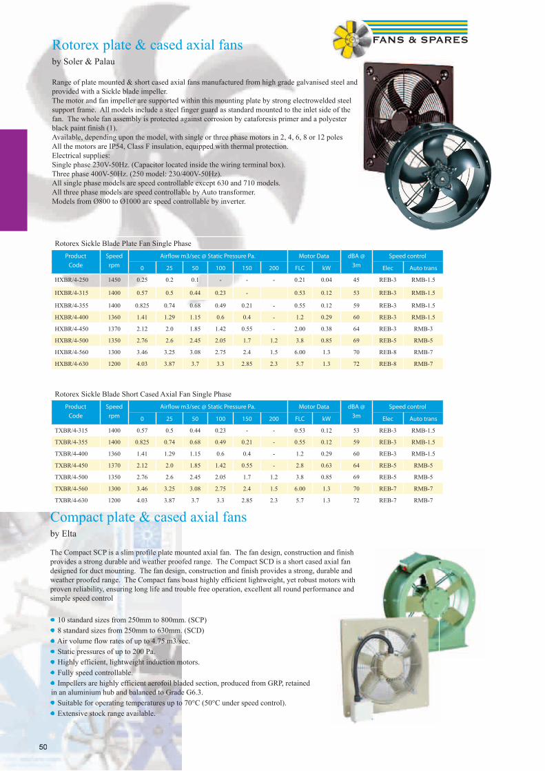
50
Rotorex Sickle Blade Plate Fan Single PhaseProduct
Code
Speed
rpm
Airfl ow m3/sec @ Static Pressure Pa. Motor Data dBA @
3m
Speed control
0 25 50 100 150 200 FLC kW Elec Auto trans
HXBR/4-250 1450 0.25 0.2 0.1 - - - 0.21 0.04 45 REB-3 RMB-1.5
HXBR/4-315 1400 0.57 0.5 0.44 0.23 - 0.53 0.12 53 REB-3 RMB-1.5
HXBR/4-355 1400 0.825 0.74 0.68 0.49 0.21 - 0.55 0.12 59 REB-3 RMB-1.5
HXBR/4-400 1360 1.41 1.29 1.15 0.6 0.4 - 1.2 0.29 60 REB-3 RMB-1.5
HXBR/4-450 1370 2.12 2.0 1.85 1.42 0.55 - 2.00 0.38 64 REB-3 RMB-3
HXBR/4-500 1350 2.76 2.6 2.45 2.05 1.7 1.2 3.8 0.85 69 REB-5 RMB-5
HXBR/4-560 1300 3.46 3.25 3.08 2.75 2.4 1.5 6.00 1.3 70 REB-8 RMB-7
HXBR/4-630 1200 4.03 3.87 3.7 3.3 2.85 2.3 5.7 1.3 72 REB-8 RMB-7
Rotorex Sickle Blade Short Cased Axial Fan Single PhaseProduct
Code
Speed
rpm
Airfl ow m3/sec @ Static Pressure Pa. Motor Data dBA @
3m
Speed control
0 25 50 100 150 200 FLC kW Elec Auto trans
TXBR/4-315 1400 0.57 0.5 0.44 0.23 - - 0.53 0.12 53 REB-3 RMB-1.5
TXBR/4-355 1400 0.825 0.74 0.68 0.49 0.21 - 0.55 0.12 59 REB-3 RMB-1.5
TXBR/4-400 1360 1.41 1.29 1.15 0.6 0.4 - 1.2 0.29 60 REB-3 RMB-1.5
TXBR/4-450 1370 2.12 2.0 1.85 1.42 0.55 - 2.8 0.63 64 REB-5 RMB-5
TXBR/4-500 1350 2.76 2.6 2.45 2.05 1.7 1.2 3.8 0.85 69 REB-5 RMB-5
TXBR/4-560 1300 3.46 3.25 3.08 2.75 2.4 1.5 6.00 1.3 70 REB-7 RMB-7
TXBR/4-630 1200 4.03 3.87 3.7 3.3 2.85 2.3 5.7 1.3 72 REB-7 RMB-7
Range of plate mounted & short cased axial fans manufactured from high grade galvanised steel and provided with a Sickle blade impeller. The motor and fan impeller are supported within this mounting plate by strong electrowelded steel support frame. All models include a steel finger guard as standard mounted to the inlet side of the fan. The whole fan assembly is protected against corrosion by cataforesis primer and a polyester black paint finish (1). Available, depending upon the model, with single or three phase motors in 2, 4, 6, 8 or 12 poles All the motors are IP54, Class F insulation, equipped with thermal protection. Electrical supplies:Single phase 230V-50Hz. (Capacitor located inside the wiring terminal box). Three phase 400V-50Hz. (250 model: 230/400V-50Hz).All single phase models are speed controllable except 630 and 710 models.All three phase models are speed controllable by Auto transformer. Models from Ø800 to Ø1000 are speed controllable by inverter.
Rotorex plate & cased axial fansby Soler & Palau
50
Compact plate & cased axial fansby Elta
The Compact SCP is a slim profile plate mounted axial fan. The fan design, construction and finish provides a strong durable and weather proofed range. The Compact SCD is a short cased axial fan designed for duct mounting. The fan design, construction and finish provides a strong, durable and weather proofed range. The Compact fans boast highly efficient lightweight, yet robust motors with proven reliability, ensuring long life and trouble free operation, excellent all round performance and simple speed control
• 10 standard sizes from 250mm to 800mm. (SCP)• 8 standard sizes from 250mm to 630mm. (SCD)• Air volume flow rates of up to 4.75 m3/sec.• Static pressures of up to 200 Pa.• Highly efficient, lightweight induction motors.• Fully speed controllable.• Impellers are highly efficient aerofoil bladed section, produced from GRP, retained in an aluminium hub and balanced to Grade G6.3.• Suitable for operating temperatures up to 70°C (50°C under speed control).• Extensive stock range available.

51
SLCAdjustable pitch longcased axial fansby Elta
• Long cased axial fan. 315mm to 630mm• Fan - single Phase. 240V - 1Ph - 50Hz (1-fi xed 2-variable) • Adjustable pitch aerofoil impellers• IP55 motors• Suitable for temperatures up to 54ºC• Tested to ISO5801• Emergency smoke fan available. please enquire
Single PhaseProduct
Code
Speed
rpm
Airfl ow m3/sec @ Static Pressure Pa. Motor Data dBA @
3m
Speed control
0 50 100 150 200 250 FLC SC kW Elec Auto trans
SLC315/4-2 1300 0.63 0.55 0.38 - - 1.09 2.3 0.12 45 EL31 TC12
SLC315/2-1 2750 1.26 1.20 1.13 1.06 0.98 0.87 3.20 9.77 0.55 54
SLC355/4-2 1300 0.85 0.76 0.63 - - 1.51 3.69 0.18 48 EL31 TC12
SLC355/2-1 2820 1.42 1.39 1.36 1.32 1.30 1.26 6.30 20.0 1.1 64
SLC400/4-2 1350 1.44 1.32 1.15 - - 2.56 5.93 0.37 52 EL31 TC14
SLC400/2/1 2780 2.07 2.03 1.98 1.92 1.88 1.84 8.10 30.1 1.5 66
SLC450/4-2A 1350 1.68 1.56 1.40 1.12 - 2.56 5.93 0.37 55 EL31 TC14
SLC450/4-2B 1350 2.07 1.89 1.67 1.38 - 3.7 11.9 0.55 55 EL61 TC18
SLC450/2-1 2780 3.03 2.93 2.84 2.73 2.62 2.51 8.10 30.1 1.5 68
SLC500/4-2A 1350 1.81 1.70 1.57 1.36 1.00 2.56 5.93 0.37 58 EL31 TC14
SLC500/4-2B 1380 2.58 2.42 2.22 2.00 1.64 4.52 11.3 0.75 58 EL61 TC18
SLC560/4-2A 1380 2.90 2.78 2.62 2.42 2.10 4.52 11.3 0.75 59 EL61 TC18
SLC560/4-2B 1350 3.35 3.15 2.96 2.71 2.35 6.28 16.4 1.0 59 EL101 TC18
SLC630/6-1A 950 2.54 2.28 1.86 - - 2.3 5.25 0.37 58
SLC630/6-1B 950 3.31 2.95 2.48 - - 3.92 9.75 0.55 58
SLC630/4-2 1350 3.72 3.56 3.36 3.12 2.78 2.22 6.28 16.4 1.0 64 EL101 TC18
DimensionsSLC A B C D E F G K Weight/kg
315 315 375 300 225 8 10 355 20 17
355 350 425 375 245 8 10 395 20 26
400 400 475 400 265 8 12 450 20 31
450 450 530 375 290 8 12 500 20 30
450/2-3B 450 530 450 290 8 12 500 25 45
500 500 585 400 315 12 12 560 20 33
500/2-3 500 585 450 315 12 12 560 25 52
560 560 645 400 345 12 12 620 20 40
560/2-3 560 645 570 345 12 12 620 20 96
630 630 715 400 380 12 12 690 20 50
630/4-3B 630 715 450 380 12 12 690 20 58
710 710 795 450 420 16 12 770 20 70
800 800 885 450 465 16 12 860 25 75
900/4-3A 900 1000 570 515 16 15 970 25 135
900/4-3B 900 1000 710 515 16 15 970 32 183
1000/4-3A 1000 1110 590 565 16 15 1070 25 143
1000/4-3B 1000 1110 790 565 16 15 1070 32 222
1000/4-3C 1000 1110 790 565 16 15 1070 32 239
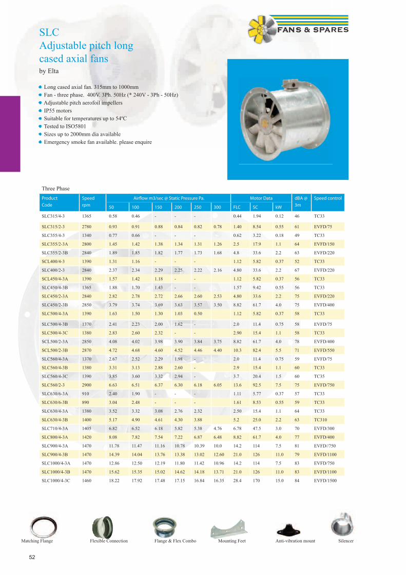
52
SLCAdjustable pitch long cased axial fansby Elta
• Long cased axial fan. 315mm to 1000mm• Fan - three phase. 400V. 3Ph. 50Hz (* 240V - 3Ph - 50Hz)• Adjustable pitch aerofoil impellers• IP55 motors• Suitable for temperatures up to 54ºC• Tested to ISO5801• Sizes up to 2000mm dia available• Emergency smoke fan available. please enquire
Three Phase
Product
Code
Speed
rpm
Airfl ow m3/sec @ Static Pressure Pa. Motor Data dBA @
3m
Speed control
50 100 150 200 250 300 FLC SC kW
SLC315/4-3 1365 0.58 0.46 - - - 0.44 1.94 0.12 46 TC33
SLC315/2-3 2780 0.93 0.91 0.88 0.84 0.82 0.78 1.40 8.54 0.55 61 EVFD/75
SLC355/4-3 1340 0.77 0.66 - - - 0.62 3.22 0.18 49 TC33
SLC355/2-3A 2800 1.45 1.42 1.38 1.34 1.31 1.26 2.5 17.9 1.1 64 EVFD/150
SLC355/2-3B 2840 1.89 1.85 1.82 1.77 1.73 1.68 4.8 33.6 2.2 63 EVFD/220
SCL400/4-3 1390 1.31 1.16 - - - 1.12 5.82 0.37 52 TC33
SLC400/2-3 2840 2.37 2.34 2.29 2.25 2.22 2.16 4.80 33.6 2.2 67 EVFD/220
SCL450/4-3A 1390 1.57 1.42 1.18 - - 1.12 5.82 0.37 56 TC33
SLC450/4-3B 1365 1.88 1.70 1.43 - - 1.57 9.42 0.55 56 TC33
SLC450/2-3A 2840 2.82 2.78 2.72 2.66 2.60 2.53 4.80 33.6 2.2 75 EVFD/220
SLC450/2-3B 2850 3.79 3.74 3.69 3.63 3.57 3.50 8.82 61.7 4.0 75 EVFD/400
SLC500/4-3A 1390 1.63 1.50 1.30 1.03 0.50 1.12 5.82 0.37 58 TC33
SLC500/4-3B 1370 2.41 2.23 2.00 1.62 - 2.0 11.4 0.75 58 EVFD/75
SLC500/4-3C 1380 2.83 2.60 2.32 - - 2.90 15.4 1.1 58 TC33
SCL500/2-3A 2850 4.08 4.02 3.98 3.90 3.84 3.75 8.82 61.7 4.0 78 EVFD/400
SCL500/2-3B 2870 4.72 4.68 4.60 4.52 4.46 4.40 10.3 82.4 5.5 71 EVFD/550
SLC560/4-3A 1370 2.67 2.52 2.29 1.98 - 2.0 11.4 0.75 59 EVFD/75
SLC560/4-3B 1380 3.31 3.13 2.88 2.60 - 2.9 15.4 1.1 60 TC33
SLC560/4-3C 1390 3.85 3.60 3.32 2.94 - 3.7 20.4 1.5 60 TC35
SLC560/2-3 2900 6.63 6.51 6.37 6.30 6.18 6.05 13.6 92.5 7.5 75 EVFD/750
SLC630/6-3A 910 2.40 1.90 - - - 1.11 5.77 0.37 57 TC33
SLC630/6-3B 890 3.04 2.48 - - - 1.61 8.53 0.55 59 TC33
SLC630/4-3A 1380 3.52 3.32 3.08 2.76 2.32 2.50 15.4 1.1 64 TC33
SLC630/4-3B 1400 5.17 4.90 4.61 4.30 3.88 5.2 25.0 2.2 63 TC310
SLC710/4-3A 1405 6.82 6.52 6.18 5.82 5.38 4.76 6.78 47.5 3.0 70 EVFD/300
SLC800/4-3A 1420 8.08 7.82 7.54 7.22 6.87 6.48 8.82 61.7 4.0 77 EVFD/400
SLC900/4-3A 1470 11.78 11.47 11.16 10.78 10.39 10.0 14.2 114 7.5 81 EVFD//750
SLC900/4-3B 1470 14.39 14.04 13.76 13.38 13.02 12.60 21.0 126 11.0 79 EVFD/1100
SLC1000/4-3A 1470 12.86 12.50 12.19 11.80 11.42 10.96 14.2 114 7.5 83 EVFD/750
SLC1000/4-3B 1470 15.62 15.35 15.02 14.62 14.18 13.71 21.0 126 11.0 83 EVFD/1100
SLC1000/4-3C 1460 18.22 17.92 17.48 17.15 16.84 16.35 28.4 170 15.0 84 EVFD/1500
Matching Flange Flexible Connection Flange & Flex Combo Mounting Feet Anti-vibration mount Silencer
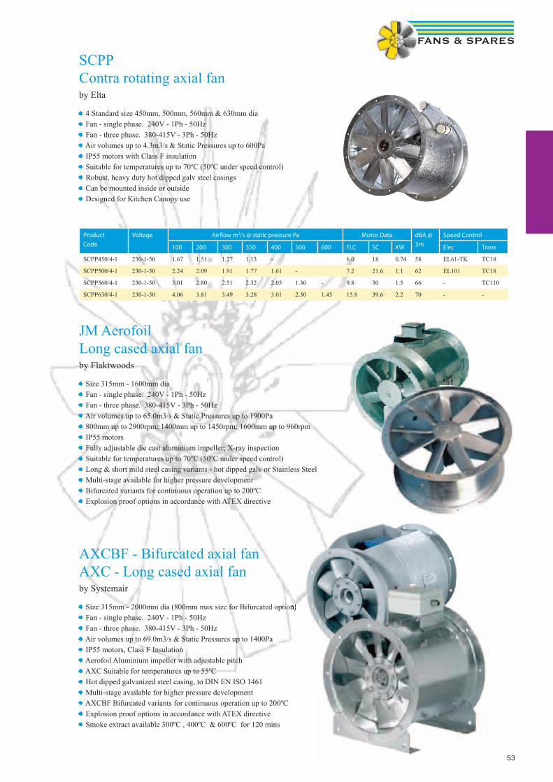
53
SCPPContra rotating axial fanby Elta
• 4 Standard size 450mm, 500mm, 560mm & 630mm dia• Fan - single phase. 240V - 1Ph - 50Hz • Fan - three phase. 380-415V - 3Ph - 50Hz • Air volumes up to 4.3m3/s & Static Pressures up to 600Pa• IP55 motors with Class F insulation• Suitable for temperatures up to 70ºC (50ºC under speed control)• Robust, heavy duty hot dipped galv steel casings• Can be mounted inside or outside• Designed for Kitchen Canopy use
JM AerofoilLong cased axial fanby Flaktwoods
• Size 315mm - 1600mm dia• Fan - single phase. 240V - 1Ph - 50Hz • Fan - three phase. 380-415V - 3Ph - 50Hz • Air volumes up to 65.0m3/s & Static Pressures up to 1900Pa• 800mm up to 2900rpm; 1400mm up to 1450rpm; 1600mm up to 960rpm• IP55 motors • Fully adjustable die cast aluminium impeller; X-ray inspection• Suitable for temperatures up to 70ºC (50ºC under speed control)• Long & short mild steel casing variants - hot dipped galv or Stainless Steel• Multi-stage available for higher pressure development• Bifurcated variants for continuous operation up to 200ºC• Explosion proof options in accordance with ATEX directive
AXCBF - Bifurcated axial fanAXC - Long cased axial fanby Systemair
• Size 315mm - 2000mm dia (800mm max size for Bifurcated option)• Fan - single phase. 240V - 1Ph - 50Hz • Fan - three phase. 380-415V - 3Ph - 50Hz • Air volumes up to 69.0m3/s & Static Pressures up to 1400Pa• IP55 motors, Class F Insulation• Aerofoil Aluminium impeller with adjustable pitch• AXC Suitable for temperatures up to 55ºC • Hot dipped galvanized steel casing, to DIN EN ISO 1461• Multi-stage available for higher pressure development• AXCBF Bifurcated variants for continuous operation up to 200ºC• Explosion proof options in accordance with ATEX directive• Smoke extract available 300ºC , 400ºC & 600ºC for 120 mins
Size 315mm - 2000mm dia (800mm max size for Bifurcated option)
Product
Code
Voltage Airfl ow m3/s @ static pressure Pa Motor Data dBA @
3m
Speed Control
100 200 300 350 400 500 600 FLC SC KW Elec Trans
SCPP450/4-1 230-1-50 1.67 1.51 1.27 1.13 - 6.0 18 0.74 58 EL61-TK TC18
SCPP500/4-1 230-1-50 2.24 2.09 1.91 1.77 1.61 - 7.2 21.6 1.1 62 EL101 TC18
SCPP560/4-1 230-1-50 3.01 2.80 2.51 2.32 2.05 1.30 - 9.8 30 1.5 66 - TC110
SCPP630/4-1 230-1-50 4.06 3.81 3.49 3.28 3.01 2.30 1.45 15.8 39.6 2.2 70 - -

54
TCBBx2 / TCBTx2 Contra rotating axial fan(formally badged as Turboprop)by Soler & Palau
• Contra rotating system with two fans and two complementary impellers allowing the duplication of the pressure with the same air volume.• Rolled steel casings and motor support protected bycataforesis primer and black polyester paint fi nish. Stainless steel screws• Impellers are dynamically balanced, according to ISO 1940 standard, giving vibration free operation• All the motors are IP65, Class F insulation (1), equipped with thermal protection. • All motors are speed controllable (by voltage). Three phase motors suitable for inverter control.• Ideal for Kitchen Extract Canopies
Product
Code
Voltage Airfl ow m3/s @ static pressure Pa Motor Data dBA @
3m
Speed Control
100 150 200 300 400 500 600 FLC SC KW Elec Trans
TCBBx2/4-450 230-1-50 1.74 1.67 1.6 1.43 1.19 - - 5.4 21.6 1.24 74 REB-6 RTRE 7
TCBBx2/4-500 230-1-50 2.33 2.25 2.14 1.85 1.47 - - 7.3 28.0 1.7 76 REB-8 RTRE 7
TCBBx2/4-560 230-1-50 3.67 3.57 3.45 3.19 2.89 2.56 - 15.5 56.0 3.25 78 N/A N/A
TCBBx2/4-630 230-1-50 4.5 4.35 4.19 3.8 3.29 2.66 1.79 19.0 76.0 3.0 79 N/A N/A
TCBTx2/4-450 400-3-50 1.73 1.68 1.62 1.47 1.2 - - 3.4 20.4 1.25 74 - RMT-5
TCBTx2/4-500 400-3-50 2.38 2.31 2.23 2.04 1.8 - - 3.6 21.6 1.75 76 - RMT-7
TCBTx2/4-560 400-3-50 3.63 3.54 3.44 3.2 2.9 2.66 - 5.8 34.8 3.12 78 - Inv
TCBTx2/4-630 400-3-50 4.7 4.58 4.48 4.2 3.9 3.68 3.33 8.0 48.0 4.2 79 - Inv
Dimensions
REF A B C D E N Weight/kg
TCBBx2 450 537 375 500 450 12 8 36
TCBBx2 500 595 375 560 500 12 12 38
TCBBx2 560 655 520 620 560 12 12 56
TCBBx2 630 725 520 690 630 12 12 63
Range of cylindrical cased axial fans fitted with aluminium impellers and manufactured from high grade rolled galvanised steel and protected against corrosion by cataforesis primer and black polyester paint finish. Fitted with 2 contra-rotating complementary impellers manufactured from die-cast aluminium. All models are supplied with pre-wired wiring junction box located on the outside of the fan casing for easy wiring access. Available with single or three phase 4 poles motors.
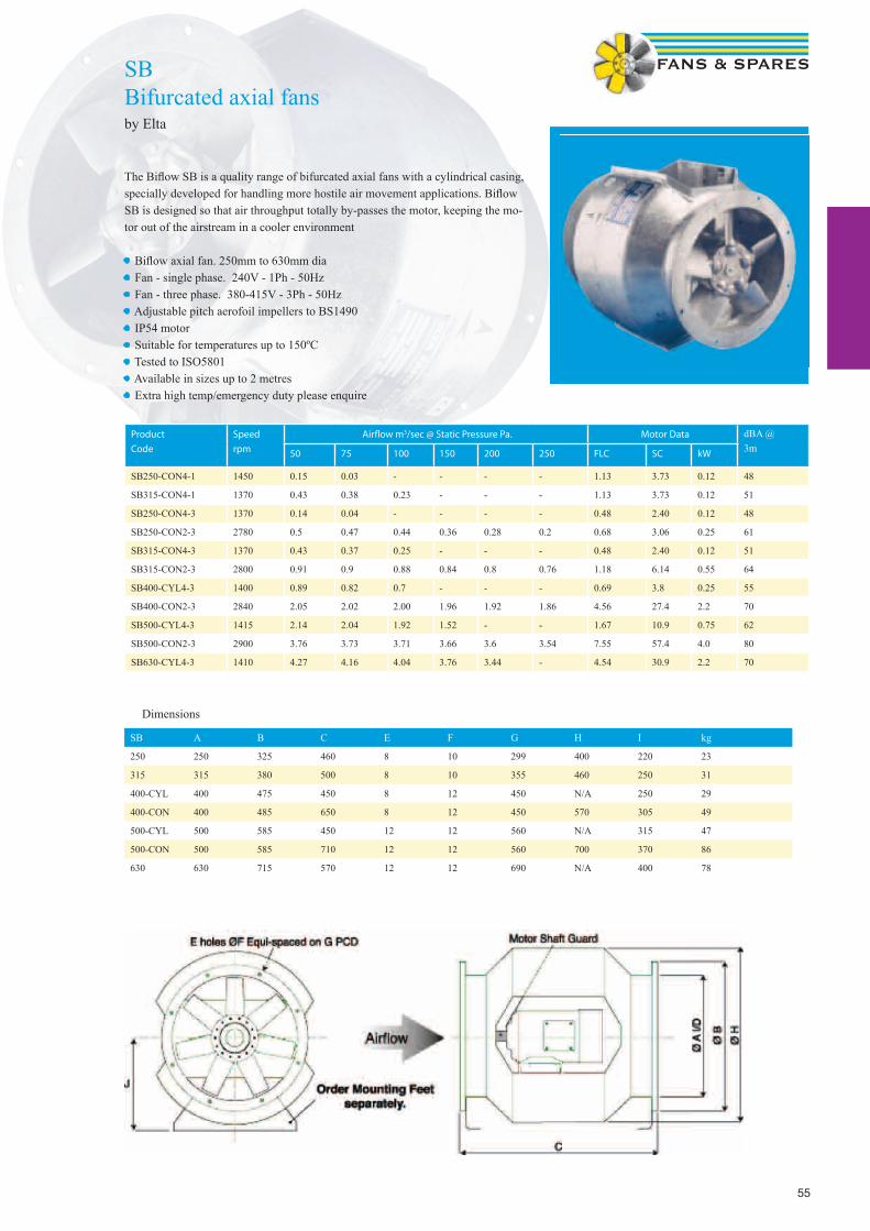
55
SBBifurcated axial fansby Elta
The Bifl ow SB is a quality range of bifurcated axial fans with a cylindrical casing, specially developed for handling more hostile air movement applications. Bifl ow SB is designed so that air throughput totally by-passes the motor, keeping the mo-tor out of the airstream in a cooler environment
• Bifl ow axial fan. 250mm to 630mm dia• Fan - single phase. 240V - 1Ph - 50Hz • Fan - three phase. 380-415V - 3Ph - 50Hz • Adjustable pitch aerofoil impellers to BS1490• IP54 motor• Suitable for temperatures up to 150ºC• Tested to ISO5801• Available in sizes up to 2 metres• Extra high temp/emergency duty please enquire
Product
Code
Speed
rpm
Airfl ow m3/sec @ Static Pressure Pa. Motor Data dBA @3m50 75 100 150 200 250 FLC SC kW
SB250-CON4-1 1450 0.15 0.03 - - - - 1.13 3.73 0.12 48
SB315-CON4-1 1370 0.43 0.38 0.23 - - - 1.13 3.73 0.12 51
SB250-CON4-3 1370 0.14 0.04 - - - - 0.48 2.40 0.12 48
SB250-CON2-3 2780 0.5 0.47 0.44 0.36 0.28 0.2 0.68 3.06 0.25 61
SB315-CON4-3 1370 0.43 0.37 0.25 - - - 0.48 2.40 0.12 51
SB315-CON2-3 2800 0.91 0.9 0.88 0.84 0.8 0.76 1.18 6.14 0.55 64
SB400-CYL4-3 1400 0.89 0.82 0.7 - - - 0.69 3.8 0.25 55
SB400-CON2-3 2840 2.05 2.02 2.00 1.96 1.92 1.86 4.56 27.4 2.2 70
SB500-CYL4-3 1415 2.14 2.04 1.92 1.52 - - 1.67 10.9 0.75 62
SB500-CON2-3 2900 3.76 3.73 3.71 3.66 3.6 3.54 7.55 57.4 4.0 80
SB630-CYL4-3 1410 4.27 4.16 4.04 3.76 3.44 - 4.54 30.9 2.2 70
SB A B C E F G H I kg
250 250 325 460 8 10 299 400 220 23
315 315 380 500 8 10 355 460 250 31
400-CYL 400 475 450 8 12 450 N/A 250 29
400-CON 400 485 650 8 12 450 570 305 49
500-CYL 500 585 450 12 12 560 N/A 315 47
500-CON 500 585 710 12 12 560 700 370 86
630 630 715 570 12 12 690 N/A 400 78
Dimensions

56
TFSKRoof mounted centrifugal fanby Systemair
• Backward curved fan. 125mm to 315mm• Fan - single phase. 230V - 1Ph - 50Hz• 100% speed controllable• Maintenance free and reliable• Integral thermal contacts• Available in black & brick red• Supplied with cable & plug• Backward curved impeller with external rotor motor
Product
Code
Speed
rpm
Airfl ow m3/sec @ Static Pressure Pa. Motor Data dBA @ Speed control
50 100 150 200 300 FLC SC kW 4m Elec Trans
TFSK 125M 1965 0.037 0.022 - - - 0.13 0.5 0.025 31 SC1.5 RE1.5
TFSK 125XL 2530 0.074 0.063 0.049 0.035 0.001 0.26 0.7 0.054 41 SC1.5 RE1.5
TFSK 160 2461 0.095 0.081 0.067 0.052 0.011 0.26 0.7 0.058 44 SC1.5 RE1.5
TFSK 200 2537 0.160 0.145 0.126 0.110 0.069 0.47 1.25 0.108 48 SC1.5 RE1.5
TFSK 315M 2575 0.290 0.270 0.250 0.220 0.170 0.90 2.3 0.207 51 SC1.5 RE1.5
TFSK 315L 2341 0.350 0.330 0.300 0.270 0.230 1.35 3.5 0.307 55 SC3.0 RE1.5
TFSK A B øC E c/c F øG Weight
125M 119 144 284 321 245 9 2.5
125XL 119 144 284 321 245 9 2.5
160 120 145 334 421 330 9 3.3
200 123 160 364 421 330 9 4.2
315M/L 160 206 404 521 450 11 7
These fans are suitable for exhaust-air ventilation systems, e.g. single and multiple dwellings, offices and day nurseries. To protect the motors from overheating, all motors have an integral thermal contact with automatic reset. The fans are manufactured in powder-coated, galvanized sheet steel and are delivered in the standard colours of black or brick red.
TFSR Roof Fansby Systemair• Swing-out Access to Motor & Impeller• Speed-controllable• Easy to install• Full range of accessories
The TFSR range consists of roof fans with circular connection and are fitted with a single-inlet centrifugal fan with backward-curved blades and external rotor motors. The motors can be tilted outwards to facilitate inspection and service. They have in-tegral on/off switch and are supplied with 1 m cable for fast connection to the mains e.g. via the connection box on the roof curb TOB or TOS.These fans are suitable for exhaust-air ventilation systems, e.g. single and multiple dwellings, offices and day nurseries. To protect the motors from overheating, all motors have an integral thermal contact with automatic reset. The fans are manu-factured in powder-coated, galvanized sheet steel and are delivered in the standard colours of black or brick red.TFSR is delivered with a spigot connection if the installation requires direct duct connection. TFSR 125-160 are delivered with a Ø 160 spigot and TFSR 200-315 with a Ø 200. The spigot is not pre-assembled to the fan.
The TFSR range consists of roof fans with circular connection and are fitted with a single-inlet centrifugal fan with backward-curved blades and external rotor motors. The motors can be tilted outwards to facilitate inspection and service. They have in-tegral on/off switch and are supplied with 1 m cable for fast connection to the mains
TFSR A B øC øD HC Weight
125M/XL 119 144 284 315 205 2.5
160 120 145 334 380 205 3.3
200 123 160 364 439 250 4.2
315M/L 160 206 404 485 250 7
The TFSK range consists of roof fans with square connection and are fitted with a single-inlet centrifugal fan with backward-curved blades and external rotor motors. The motors can be tilted outwards to facilitate inspection and service. They have integral on/off switch and are supplied with 1 m cable and are easy connected to our standard roof curbs TG, FDS and SSD.
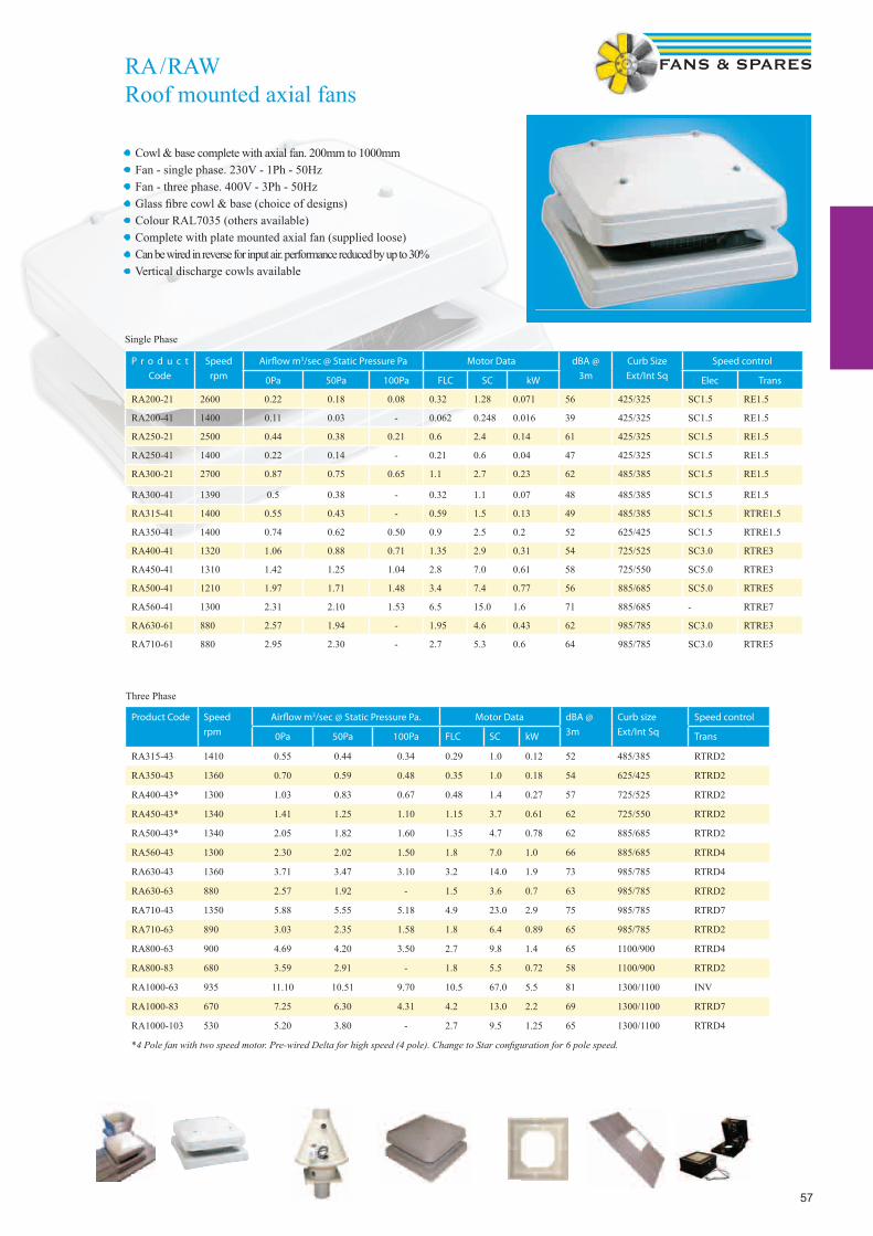
57
RA / RAWRoof mounted axial fans
• Cowl & base complete with axial fan. 200mm to 1000mm• Fan - single phase. 230V - 1Ph - 50Hz• Fan - three phase. 400V - 3Ph - 50Hz• Glass fi bre cowl & base (choice of designs)• Colour RAL7035 (others available)• Complete with plate mounted axial fan (supplied loose)• Can be wired in reverse for input air. performance reduced by up to 30%• Vertical discharge cowls available
P r o d u c t
Code
Speed
rpm
Airfl ow m3/sec @ Static Pressure Pa Motor Data dBA @
3m
Curb Size
Ext/Int Sq
Speed control
0Pa 50Pa 100Pa FLC SC kW Elec Trans
RA200-21 2600 0.22 0.18 0.08 0.32 1.28 0.071 56 425/325 SC1.5 RE1.5
RA200-41 1400 0.11 0.03 - 0.062 0.248 0.016 39 425/325 SC1.5 RE1.5
RA250-21 2500 0.44 0.38 0.21 0.6 2.4 0.14 61 425/325 SC1.5 RE1.5
RA250-41 1400 0.22 0.14 - 0.21 0.6 0.04 47 425/325 SC1.5 RE1.5
RA300-21 2700 0.87 0.75 0.65 1.1 2.7 0.23 62 485/385 SC1.5 RE1.5
RA300-41 1390 0.5 0.38 - 0.32 1.1 0.07 48 485/385 SC1.5 RE1.5
RA315-41 1400 0.55 0.43 - 0.59 1.5 0.13 49 485/385 SC1.5 RTRE1.5
RA350-41 1400 0.74 0.62 0.50 0.9 2.5 0.2 52 625/425 SC1.5 RTRE1.5
RA400-41 1320 1.06 0.88 0.71 1.35 2.9 0.31 54 725/525 SC3.0 RTRE3
RA450-41 1310 1.42 1.25 1.04 2.8 7.0 0.61 58 725/550 SC5.0 RTRE3
RA500-41 1210 1.97 1.71 1.48 3.4 7.4 0.77 56 885/685 SC5.0 RTRE5
RA560-41 1300 2.31 2.10 1.53 6.5 15.0 1.6 71 885/685 - RTRE7
RA630-61 880 2.57 1.94 - 1.95 4.6 0.43 62 985/785 SC3.0 RTRE3
RA710-61 880 2.95 2.30 - 2.7 5.3 0.6 64 985/785 SC3.0 RTRE5
Single Phase
Product Code Speed
rpm
Airfl ow m3/sec @ Static Pressure Pa. Motor Data dBA @
3m
Curb size
Ext/Int Sq
Speed control
0Pa 50Pa 100Pa FLC SC kW Trans
RA315-43 1410 0.55 0.44 0.34 0.29 1.0 0.12 52 485/385 RTRD2
RA350-43 1360 0.70 0.59 0.48 0.35 1.0 0.18 54 625/425 RTRD2
RA400-43* 1300 1.03 0.83 0.67 0.48 1.4 0.27 57 725/525 RTRD2
RA450-43* 1340 1.41 1.25 1.10 1.15 3.7 0.61 62 725/550 RTRD2
RA500-43* 1340 2.05 1.82 1.60 1.35 4.7 0.78 62 885/685 RTRD2
RA560-43 1300 2.30 2.02 1.50 1.8 7.0 1.0 66 885/685 RTRD4
RA630-43 1360 3.71 3.47 3.10 3.2 14.0 1.9 73 985/785 RTRD4
RA630-63 880 2.57 1.92 - 1.5 3.6 0.7 63 985/785 RTRD2
RA710-43 1350 5.88 5.55 5.18 4.9 23.0 2.9 75 985/785 RTRD7
RA710-63 890 3.03 2.35 1.58 1.8 6.4 0.89 65 985/785 RTRD2
RA800-63 900 4.69 4.20 3.50 2.7 9.8 1.4 65 1100/900 RTRD4
RA800-83 680 3.59 2.91 - 1.8 5.5 0.72 58 1100/900 RTRD2
RA1000-63 935 11.10 10.51 9.70 10.5 67.0 5.5 81 1300/1100 INV
RA1000-83 670 7.25 6.30 4.31 4.2 13.0 2.2 69 1300/1100 RTRD7
RA1000-103 530 5.20 3.80 - 2.7 9.5 1.25 65 1300/1100 RTRD4
*4 Pole fan with two speed motor. Pre-wired Delta for high speed (4 pole). Change to Star confi guration for 6 pole speed.
Three Phase

58
RARoof Cowl DimensionsRA horizontal discharge roof cowls from Systemair are manufactured from glass reinforced plastic. with an ultra violet stabilis-er and are precision moulded to provide a durable unit for the severest weather conditions without deterioration of fi nish. The standard colour fi nish is RAL 7035. but any B.S. or RAL colour can be provided if required.
A full range of ancillary items are available. including: bird guards. back draught shutters. purlin boxes and soaker sheets. RA roof fans are suitable for extract and supply air.
* Weight of RA shown in the chart includes an AW1 plate fan.
Model ref. A sq. B sq. C D sq. E Weight kg*
RA200 325 450 90 490 310 18
RA250 325 450 90 490 310 18
RA300 400 510 90 555 340 20
RA315 400 510 90 555 340 20
RA350 400 650 90 675 380 22
RA400 500 750 90 765 460 26
RA450 550 750 90 765 460 29
RA500 650 910 120 995 550 44
RA560 650 910 120 995 550 47
RA630 790 1010 120 1115 650 70
RA710 790 1010 120 1115 650 73
RA800 900 1165 100 1410 750 65
RA1000 1100 1360 80 1650 750 100 - 140
N
* Bird guard fi tted as standard* Air operated shutter available - Ref BDS(“size of cowl”)
See page 130 for RAL colour chart options
C
D
A
B
C
D
A
B
E
Other Roof Cowls available(Coloured / Metal - please enquire)
LGV - Vertical DischargeLGH - Low Profile DischargeMetal Roof Cowls availableSizes 225 - 900
Coloured Cowls to anyRAL or BS colour
EFS-RCK 5-in-1 Roof Cowl with flashing. Cut off Spigot (100mm, 110mm, 125mm, 150mm &160mm Dia)
Metal Roof Cowls complete with flashing and duct connector (Sizes 125mm - 400mm Dia ) Brick Red or Slate Grey Colour Options
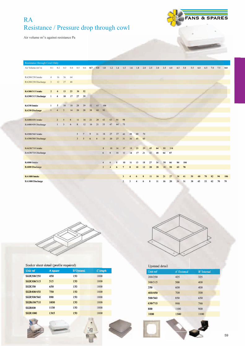
59
RAResistance / Pressure drop through cowlAir volume m3/s against resistance Pa
Resistance through Cowl Only
Air Volume (m3/s) 0.1 0.2 0.3 0.4 0.5 0.6 0.7 0.8 1.0 1.2 1.4 1.5 1.6 1.8 2.0 2.5 3.0 3.5 4.0 4.5 5.0 5.5 6.0 6.5 7.0 7.5 8.0
RA200/250 Intake 4 16 36 64
RA200/250 Discharge 3 12 27 48
RA300/315 Intake 2 6 13 23 36 52
RA300/315 Discharge 1 4 10 17 27 39
RA350 Intake 1 5 10 18 28 39 52 65 106
RA350 Discharge 1 4 7 14 20 28 38 60 90
RA400/450 Intake 2 5 8 11 16 21 28 43 63 86 98
RA400/450 Discharge 1 3 6 8 12 16 21 33 47 64 73
RA500/560 Intake 5 7 9 11 18 27 37 42 46 60 74
RA500/560 Discharge 3 5 6 8 13 20 27 31 36 45 65
RA630/710 Intake 8 10 14 17 18 23 29 45 64 88 114
RA630/710 Discharge 6 8 10 12 14 17 21 32 48 64 87
RA800 Intake 4 6 8 10 11 13 18 27 36 50 66 84 104
RA800 Discharge 2 4 6 7 8 10 12 20 28 38 50 63 78
RA1000 Intake 3 4 6 8 11 16 21 27 34 41 50 60 70 82 94 106
RA1000 Discharge 2 3 4 6 8 11 16 20 26 31 38 45 53 62 70 79
Soaker sheet detail (profi le required)Unit ref A square B Upstand C length
SKR200/250 450 150 1800
SKR300/315 515 150 1800
SKR350 650 150 1800
SKR400/450 750 150 1800
SKR500/560 890 150 1800
SKR630/710 1000 150 1800
SKR800 1130 150 1800
SKR1000 1365 150 1800
Upstand detailUnit ref A’ External B’ Internal
200/250 425 325
300/315 500 400
350 600 400
400/450 700 500
500/560 850 650
630/710 990 790
800 1100 900
1000 1300 1100
0.7 0.8 1.0 1.2 1.4 1.5 1.6 1.8 2.0 2.5 3.0 3.5 4.0 4.5 5.0 5.5 6.0 6.5 7.0 7.5 8.0
RA300/315 Intake 2 6 13 23 36 52
RA300/315 Discharge 1 4 10 17 27 39
RA350 Intake 1 5 10 18 28 39
RA350 Discharge 1 4 7 14 20 28
RA400/450 Intake 2 5 8 11 16
RA400/450 Discharge 1 3 6 8 12
RA500/560 Intake 5 7
RA500/560 Discharge 3 5
RA630/710 Intake
RA630/710 Discharge 6 8 10 12 14 17 21 32 48 64 87
RA800 Intake 4 6 8 10 11 13 18 27 36 50 66 84 104
RA800 Discharge 2 4 6 7 8 10 12 20 28 38 50 63 78
RA1000 Intake 3 4 6 8 11 16 21 27 34 41 50 60 70 82 94 106
RA1000 Discharge 2 3 4 6 8 11 16 20 26 31 38 45 53 62 70 79
C length
1800
1800
1800
1800
1800
1800
1800
1800
Unit ref A’ External B’ Internal
200/250 425 325
300/315 500 400
350 600 400
400/450 700 500
500/560 850 650
630/710 990 790
800 1100 900
1000 1300 1100
C lengthUpstand detailUnit ref A’ External B’ Internal
52 65 106
38 60 90
21 28 43 63 86 98
16 21 33 47 64 73
9 11 18 27 37 42 46 60 74
6 8 13 20 27 31 36 45 65
8 10 14 17 18 23 29 45 64 88 114
6 8 10 12 14 17 21 32 48 64 87
Soaker sheet detail (profi le required)Unit ref A square B Upstand C length
SKR200/250 450 150 1800
SKR300/315 515 150 1800
SKR350 650 150 1800
SKR400/450 750 150 1800
SKR500/560 890 150 1800
SKR630/710 1000 150 1800
SKR800 1130 150 1800
SKR1000 1365 150 1800
Soaker sheet detail (profi le required)Unit ref A square B Upstand C length
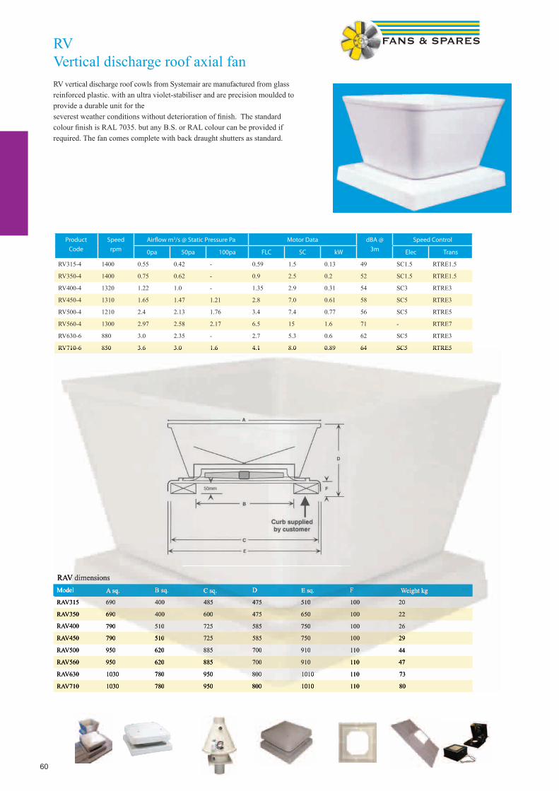
60
RVVertical discharge roof axial fanRV vertical discharge roof cowls from Systemair are manufactured from glass reinforced plastic. with an ultra violet-stabiliser and are precision moulded to provide a durable unit for the severest weather conditions without deterioration of fi nish. The standard colour fi nish is RAL 7035. but any B.S. or RAL colour can be provided if required. The fan comes complete with back draught shutters as standard.
RAV dimensions
Model A sq. B sq. C sq. D E sq. F Weight kg
RAV315 690 400 485 475 510 100 20
RAV350 690 400 600 475 650 100 22
RAV400 790 510 725 585 750 100 26
RAV450 790 510 725 585 750 100 29
RAV500 950 620 885 700 910 110 44
RAV560 950 620 885 700 910 110 47
RAV630 1030 780 950 800 1010 110 73
RAV710 1030 780 950 800 1010 110 80
Product
Code
Speed
rpm
Airfl ow m3/s @ Static Pressure Pa Motor Data dBA @
3m
Speed Control
0pa 50pa 100pa FLC SC kW Elec Trans
RV315-4 1400 0.55 0.42 - 0.59 1.5 0.13 49 SC1.5 RTRE1.5
RV350-4 1400 0.75 0.62 - 0.9 2.5 0.2 52 SC1.5 RTRE1.5
RV400-4 1320 1.22 1.0 - 1.35 2.9 0.31 54 SC3 RTRE3
RV450-4 1310 1.65 1.47 1.21 2.8 7.0 0.61 58 SC5 RTRE3
RV500-4 1210 2.4 2.13 1.76 3.4 7.4 0.77 56 SC5 RTRE5
RV560-4 1300 2.97 2.58 2.17 6.5 15 1.6 71 - RTRE7
RV630-6 880 3.0 2.35 - 2.7 5.3 0.6 62 SC5 RTRE3
RV710-6 850 3.6 3.0 1.6 4.1 8.0 0.89 64 SC5 RTRE5
RAV dimensionsModel A sq. B sq. C sq. D E sq. F Weight kg
RAV315 690 400 485 475 510 100 20
RAV350 690 400 600 475 650 100 22
RAV400 790 510 725 585 750 100 26
RAV450 790 510 725 585 750 100 29
RAV500 950 620 885 700 910 110 44
RAV560 950 620 885 700 910 110 47
RAV630 1030 780 950 800 1010 110 73
RAV710 1030 780 950 800 1010 110 80
RV710-6 850 3.6 3.0 1.6 4.1 8.0 0.89 64 SC5 RTRE5
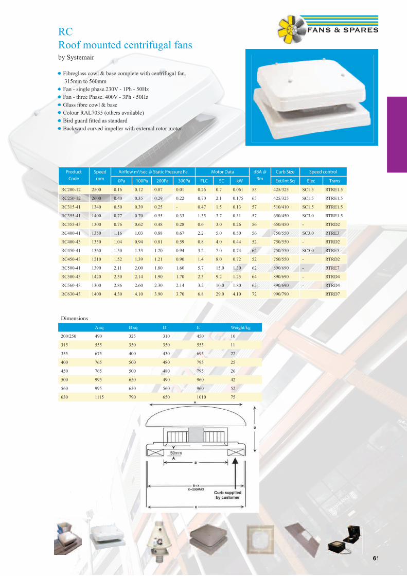
6161
RCRoof mounted centrifugal fansby Systemair
• Fibreglass cowl & base complete with centrifugal fan. 315mm to 560mm• Fan - single phase.230V - 1Ph - 50Hz• Fan - three Phase. 400V - 3Ph - 50Hz• Glass fi bre cowl & base• Colour RAL7035 (others available)• Bird guard fi tted as standard• Backward curved impeller with external rotor motor
Product
Code
Speed
rpm
Airfl ow m3/sec @ Static Pressure Pa. Motor Data dBA @
3m
Curb Size Speed control
0Pa 100Pa 200Pa 300Pa FLC SC kW Ext/Int Sq Elec Trans
RC200-12 2500 0.16 0.12 0.07 0.01 0.26 0.7 0.061 53 425/325 SC1.5 RTRE1.5
RC250-12 2600 0.40 0.35 0.29 0.22 0.70 2.1 0.175 65 425/325 SC1.5 RTRE1.5
RC315-41 1340 0.50 0.39 0.25 - 0.47 1.5 0.13 57 510/410 SC1.5 RTRE1.5
RC355-41 1400 0.77 0.70 0.55 0.33 1.35 3.7 0.31 57 650/450 SC3.0 RTRE1.5
RC355-43 1300 0.76 0.62 0.48 0.28 0.6 3.0 0.26 56 650/450 - RTRD2
RC400-41 1350 1.16 1.03 0.88 0.67 2.2 5.0 0.50 56 750/550 SC3.0 RTRE3
RC400-43 1350 1.04 0.94 0.81 0.59 0.8 4.0 0.44 52 750/550 - RTRD2
RC450-41 1360 1.50 1.33 1.20 0.94 3.2 7.0 0.74 62 750/550 SC5.0 RTRE5
RC450-43 1210 1.52 1.39 1.21 0.90 1.4 8.0 0.72 52 750/550 - RTRD2
RC500-41 1390 2.11 2.00 1.80 1.60 5.7 15.0 1.30 62 890/690 - RTRE7
RC500-43 1420 2.30 2.14 1.90 1.70 2.3 9.2 1.25 64 890/690 - RTRD4
RC560-43 1300 2.86 2.60 2.30 2.14 3.5 10.0 1.80 65 890/690 - RTRD4
RC630-43 1400 4.30 4.10 3.90 3.70 6.8 29.0 4.10 72 990/790 RTRD7
DimensionsA sq B sq D E Weight/kg
200/250 490 325 310 450 10
315 555 350 350 555 11
355 675 400 430 695 22
400 765 500 480 795 25
450 765 500 480 795 26
500 995 650 490 960 42
560 995 650 560 960 52
630 1115 790 650 1010 75
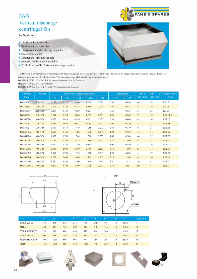
62
DVSVertical discharge centrifugal fanby Systemair
• Metal cowl construction• Roof mounted extract fan• Backward curved centrifugal impeller• Speed controllable• Maintenance free and reliable• Acoustic DVSI version available• DHS - Low profi le Horizontal discharge version
Product
Code
Voltage Airfl ow m3/s @ static pressure Pa Motor Data dBA @
10m DVS
dBA @
10m DVSI
Speed Control
Trans0 50 100 200 300 FLC kW
DVS190EZ 230-1-50 0.133 0.113 0.100 0.064 0.020 0.36 0.080 40 36 RE1.5
DVS225EZ 230-1-50 0.272 0.250 0.225 0.169 0.094 0.50 0.113 41 36 RE1.5
DVS311EV 230-1-50 0.488 0.438 0.380 0.211 - 0.60 0.135 37 28 RE1.5
DVS355E4 230-1-50 0.791 0.730 0.680 0.519 0.238 1.20 0.260 39 30 RTRE1.5
DVS400DV 400-3-50 1.055 1.019 0.950 0.811 0.650 0.80 0.440 43 34 RTRD2
DVS400E4 230-1-50 1.055 0.988 0.938 0.788 0.600 2.00 0.420 43 34 RTRE3
DVS450E4 230-1-50 1.583 1.519 1.419 1.258 1.000 3.40 0.770 45 36 RTRE5
DVS450DV 400-3-50 1.527 1.469 1.388 1.230 1.000 1.40 0.750 45 36 RTRD2
DVS499DV 400-3-50 1.833 1.769 1.700 1.500 1.250 1.80 0.900 46 37 RTRD2
DVS500DV 400-3-50 2.194 2.100 2.038 1.880 1.700 2.10 1.190 48 39 RTRD4
DVS500DS 400-3-50 1.500 1.350 1.250 0.838 - 1.00 0.440 38 29 RTRD2
DVS560DV 400-3-50 2.916 2.800 2.700 2.419 2.230 3.50 1.900 56 47 RTRD4
DVS560DS 400-3-50 2.097 1.900 1.750 1.300 0.500 1.50 0.680 41 32 RTRD2
DVS630DS 400-3-50 2.777 2.650 2.480 2.169 1.700 2.10 1.100 45 36 RTRD4
DVS710DS 400-3-50 3.850 3.700 3.500 3.100 2.650 3.5 2.475 50 41 RTRD7
DVS710DS-L 400-3-50 4.460 4.440 4.300 3.900 3.600 6.50 2.95 50 41 RTRD7
�A
�B
C
øD
�E
�F
G M20x1,5
G
øH(4x)
J
øD
�A
�B
C
øD
�E
�F
G M20x1,5
G
øH(4x)
J
øD
DVS oA oB C øD oE oF G øH J Weight Kg
190EZ. 225EZ 370 295 170 213 335 245 105 10 6xM6 7
311EV 560 470 330 282 435 330 146 10 6xM6 11
355E4. 400E4/DV 720 618 400 438 595 450 200 12 6xM8 25
450E4-500DS 900 748 440 438 665 535 237 12 6xM8 40
560DV/DS. 630DS 1050 1010 560 605 939 750 293 14 8xM8 58
710DS 1350 1176 660 674 1035 840 320 14 8xM8 88
The DVS/DHS/DVSI models have impellers with backward curved blades and external rotor motors. All motors are speed controllable over the voltage. Frequency inverters must have an all pole sine filter. The motors are suspended on effective vibration dampers. DVS/DHS/DVSI ...EZ / EV / ES: 1~ motor with connection for 2-speedsDVS/DHS/DVSI ...E4: 1-speed motorDVS/DHS/DVSI ...DV / DS: 3~ with Y/D-connection for 2-speeds

63
DVC-S / -P / -POC+FTG / -PK / -SKRoof Mounted Extract FanWith EC - Motorsby Systemair
• 100 % speed controllable• Integrated motor protection• Low noise level• Safe and maintenance free operation• Energy-saving
The DVC roof fans are driven by EC- external rotor motors, so called energy saving motors with high efficiency. The input voltage for single phase units can vary between 200 and 277V, for three phase units between 380 and 480V. All motors are suitable for 50Hz and 60Hz and from size 355 up to 630 suspended on effective vibration dampers .Motor protection is integrated in the electronics of the motor, no additional external motor protection device is needed. Casing from seawa-ter-resistant aluminium, base frame powder coated. Backward curved impellers manufactured from polyamide PA 6 for size 190 and 315. From 355 up to 630 impellers manufactured from seawater resistant aluminium.The DVC-POC versions have integrated pressure sensors and temperature sensor for outdoor temperature compensation. The electronics could be programmed for a pressure constant operation or pressure constant operation with outdoor temperature compensation. The factory setting is pressure constant operation with outdoor temperature compensation. All set point adjustments over the keyboard and all values were shown on the LC display. The DVC-P versions have integrated pressure sensors and the electronics are programmed for a pressure constant operation. Two potenti-ometers in the electronics allow for 2 set values (day/night), one additional contact for an external setting.
Product
Code
Voltage Airfl ow m3/s @ static pressure Pa RPM Motor dBA Weight
100 200 300 400 500 600 kW Amps @ 4m Kg
DVC190-S 230 / 1PH 0.174 1.45 0.109 0.072 0.28 - 3114 0.087 0.65 58 7
DVC225-P 230 / 1PH 0.237 0.215 0.18 0.152 0.113 0.071 3278 0.166 1.2 58 8
DVC225-S 230 / 1PH 0.237 0.215 0.18 0.152 0.113 0.071 3278 0.166 1.2 58 8
DVC315-P 230 / 1PH 0.44 0.33 0.19 0.09 - - 1867 0.173 1.2 47 11
DVC315-POC + FTG 230 / 1PH 0.44 0.33 0.19 0.09 - - 1867 0.173 1.2 47 11
DVC315-S 230 / 1PH 0.44 0.33 0.19 0.09 - - 1867 0.173 1.2 47 11
DVC355-P 230 / 1PH 0.81 0.73 0.62 0.51 0.28 - 1657 0.378 2.31 50 25
DVC355-POC + FTG 230 / 1PH 0.81 0.73 0.62 0.51 0.28 - 1657 0.378 2.31 50 25
DVC355-S 230 / 1PH 0.81 0.73 0.62 0.51 0.28 - 1657 0.378 2.31 50 25
DVC400-P 230 / 1PH 0.88 0.74 0.60 0.37 0.02 - 1348 0.381 2.3 49 29
DVC400-POC + FTG 230 / 1PH 0.88 0.74 0.60 0.37 0.02 - 1348 0.381 2.3 49 29
DVC400-S 230 / 1PH 0.88 0.74 0.60 0.37 0.02 - 1348 0.381 2.3 49 29
DVC450-P 400 / 3PH 1.59 1.47 1.38 1.26 1.13 0.92 1558 1.05 1.8 56 45
DVC450-PK 230 / 1PH 1.28 1.17 1.02 0.82 - - 1300 0.614 2.8 53 45
DVC450-POC + FTG 400 / 3PH 1.59 1.47 1.38 1.26 1.13 0.92 1558 1.05 1.8 56 45
DVC450-S 400 / 3PH 1.59 1.47 1.38 1.26 1.13 0.92 1558 1.05 1.8 56 43
DVC450-SK 230 / 1PH 1.28 1.17 1.02 0.82 - - 1300 0.614 2.8 53 43
DVC500-P 400 / 3PH 1.66 1.55 1.41 1.22 0.99 0.05 1339 0.984 1.66 55 49
DVC500-POC + FTG 400 / 3PH 1.66 1.55 1.41 1.22 0.99 0.05 1339 0.984 1.66 55 49
DVC500-S 400 / 3PH 1.66 1.55 1.41 1.22 0.99 0.05 1340 0.984 1.66 55 49
DVC560-P 400 / 3PH 2.78 2.61 2.39 2.19 1.97 1.74 1359 1.87 2.88 58 63
DVC560-POC 400 / 3PH 2.78 2.61 2.39 2.19 1.97 1.74 1359 1.87 2.88 58 63
DVC560-S 400 / 3PH 2.78 2.61 2.39 2.19 1.97 1.74 1359 1.87 2.88 58 63
DVC630-P 400 / 3PH 3.4 3.2 3.0 2.8 2.6 2.3 1209 2.45 3.72 64 65
DVC630-POC 400 / 3PH 3.4 3.2 3.0 2.8 2.6 2.3 1209 2.45 3.72 64 65
DVC630-S 400 / 3PH 3.4 3.2 3.0 2.8 2.6 2.3 1209 2.45 3.72 64 65
Performance & Motor details

64
DVC-S / -P / -POC+FTG / -PK / -SKRoof Mounted Extract Fan Dimensions
DVC Asq Bsq C D E sq F sq G H I K L190 370 295 170 213 335 245 105 6xM6 10(4X) 213 -225 370 295 170 213 335 245 105 6xM6 10(4X) 213 -315 370 295 330 285 435 330 146 6xM6 10(4X) 285 -315-POC 560 470 330 393 435 330 146 6xM6 10(4X) 285 443355 720 618 390 438 595 450 200 6xM8 12(4X) 438 -355-POC 720 618 390 454 595 450 200 6xM8 12(4X) 438 504400 720 618 390 438 595 450 200 6xM8 12(4X) 438 -400-POC 720 618 390 475 595 450 200 6xM8 12(4X) 438 525450 900 730 465 438 665 535 237 6xM8 12(4X) 438 -450-POC 900 730 465 530 665 535 237 6xM8 12(4X) 438 580500 900 730 465 438 665 535 237 6xM8 12(4X) 438 -500-POC 900 730 465 530 665 535 237 6xM8 12(4X) 438 580560 1150 - 560 605 939 750 293 8xM8 14(4X) 605 -560-POC 1150 955 560 - 939 750 293 8xM8 14(4X) 605 600630 1150 - 560 605 939 750 293 8xM8 14(4X) 605 -630-POC 1150 955 560 - 939 750 293 8xM8 14(4X) 605 600
DVC-OC+FTG DVC-S / -P / -PK / -SK DVC-S / -P / -POC+FTG / -PK / -SK
AFS Inlet flangeCounterflange for connection to a duct system. Manufac-
tured from galvanized steel. Suitable for DVS/DVSI, DHS,
DVN/DVNI up to 120°C.
ASK inflow chamberFor mounting on SSD socket silencers to fix inlet accessories
and duct system. Made of seawater resistant aluminium.
For DVS/DHS, DVSI, DVNI, DVN, DVC, TOE, TOV.
ASS flexible connection Manufactured from galvanised sheet steel, with neoprene
coated fabric. For temperature up to 70°C.
FDS flat roof socketManufactured from seawater resistant aluminium and
is supplied ready for assembly with insulation up to 100°C.
Suitable for DVS/DHS, DVSI, DVN, DVNI, DVC, DVEX.
SSD socket silencer For special requirements at the inlet side. The sound absorp-
tion at 250 Hz is in average 8 dB. The SSD is manufactured
from seawater resistant aluminium. The sound absorbing
material is abrasion resistant up to a velocity of 20 m/s. The
crank is extendable for service options.
Suitable for DVS/DHS, DVSI, DVN, DVNI, DVC and
DVEX.
TDA adapter framework for mounting of accessories. Adapter framework for mount-
ing into roof socket. The adapter framework consists of
galvanized steel.
TG roof curbThe brackets make it easy to fit the roof curb to the roof pitch,
and also function as a silencer. Manufactured from galvanised
sheet steel and insulated with a 50 mm rockwool sheet and
a perforated inner plate. The roof curb is fitted with plastic
piping and conduits for electric cables. A roof curb with 100
mm insulation (corresponding to A60 insulation) is available
on request.
VKS automatic shutterConsists of flanges manufactured from galvanized steel,
and of shutter blades manufactured from seawater resistant
aluminium.Suitable for DVS/DHS,DVC, DVSI, DVN.
VKM motor driven shutterConsists of flanges manufactured from galvanized steel, and of shutter
blades manufactured from seawater resistant aluminium.
Is equipped with a servo motor (230V/50Hz/25W), which can be oper-
ated manually as well as through the automatic controllers of the air
conditioning unit. While the motor is energized the shutter stays open.
When separated from the supply the shutter will close automatically.
Suitable for DVS/DHS, DVSI, DVN.
Roof Fan Ancillaries
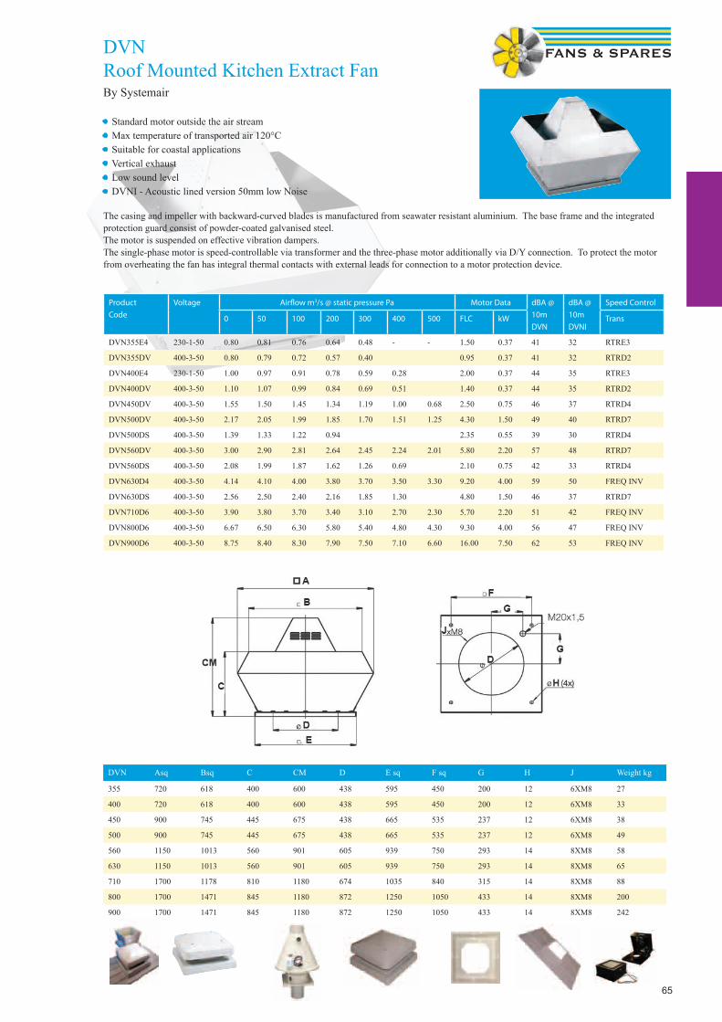
65
DVNRoof Mounted Kitchen Extract FanBy Systemair
Product
Code
Voltage Airfl ow m3/s @ static pressure Pa Motor Data dBA @
10m
DVN
dBA @
10m
DVNI
Speed Control
0 50 100 200 300 400 500 FLC kW Trans
DVN355E4 230-1-50 0.80 0.81 0.76 0.64 0.48 - - 1.50 0.37 41 32 RTRE3
DVN355DV 400-3-50 0.80 0.79 0.72 0.57 0.40 0.95 0.37 41 32 RTRD2
DVN400E4 230-1-50 1.00 0.97 0.91 0.78 0.59 0.28 2.00 0.37 44 35 RTRE3
DVN400DV 400-3-50 1.10 1.07 0.99 0.84 0.69 0.51 1.40 0.37 44 35 RTRD2
DVN450DV 400-3-50 1.55 1.50 1.45 1.34 1.19 1.00 0.68 2.50 0.75 46 37 RTRD4
DVN500DV 400-3-50 2.17 2.05 1.99 1.85 1.70 1.51 1.25 4.30 1.50 49 40 RTRD7
DVN500DS 400-3-50 1.39 1.33 1.22 0.94 2.35 0.55 39 30 RTRD4
DVN560DV 400-3-50 3.00 2.90 2.81 2.64 2.45 2.24 2.01 5.80 2.20 57 48 RTRD7
DVN560DS 400-3-50 2.08 1.99 1.87 1.62 1.26 0.69 2.10 0.75 42 33 RTRD4
DVN630D4 400-3-50 4.14 4.10 4.00 3.80 3.70 3.50 3.30 9.20 4.00 59 50 FREQ INV
DVN630DS 400-3-50 2.56 2.50 2.40 2.16 1.85 1.30 4.80 1.50 46 37 RTRD7
DVN710D6 400-3-50 3.90 3.80 3.70 3.40 3.10 2.70 2.30 5.70 2.20 51 42 FREQ INV
DVN800D6 400-3-50 6.67 6.50 6.30 5.80 5.40 4.80 4.30 9.30 4.00 56 47 FREQ INV
DVN900D6 400-3-50 8.75 8.40 8.30 7.90 7.50 7.10 6.60 16.00 7.50 62 53 FREQ INV
DVN Asq Bsq C CM D E sq F sq G H J Weight kg
355 720 618 400 600 438 595 450 200 12 6XM8 27
400 720 618 400 600 438 595 450 200 12 6XM8 33
450 900 745 445 675 438 665 535 237 12 6XM8 38
500 900 745 445 675 438 665 535 237 12 6XM8 49
560 1150 1013 560 901 605 939 750 293 14 8XM8 58
630 1150 1013 560 901 605 939 750 293 14 8XM8 65
710 1700 1178 810 1180 674 1035 840 315 14 8XM8 88
800 1700 1471 845 1180 872 1250 1050 433 14 8XM8 200
900 1700 1471 845 1180 872 1250 1050 433 14 8XM8 242
• Standard motor outside the air stream• Max temperature of transported air 120°C • Suitable for coastal applications• Vertical exhaust• Low sound level• DVNI - Acoustic lined version 50mm low Noise
The casing and impeller with backward-curved blades is manufactured from seawater resistant aluminium. The base frame and the integrated protection guard consist of powder-coated galvanised steel. The motor is suspended on effective vibration dampers.The single-phase motor is speed-controllable via transformer and the three-phase motor additionally via D/Y connection. To protect the motor from overheating the fan has integral thermal contacts with external leads for connection to a motor protection device.

66
Special Application FansSpecial Application Fanspplication Fanspplication Fans

67
FLPFlameproof axial fansby The London Fan Company
For use in hazardous areas where fl ammable gas or dust is present ATEX II 2G D [EExd Zone 1]
• Sizes from 190mm to 760mm impeller diameter• All units are fi tted with Breezax anti static blades.• Stainless steel or mild steel plates are available with non-sparking track.• Available in 110V 1Phase version. please enquire• All fans are suitable for internal or external operations at any installed angle.• Airfl ow direction is A form (B form can be supplied if required)• Operating temperatures from -20 C to 50 C
Ancillaries include : Wire safety guards & louvre shutters
Performance DataFan Ref Speed
RPM
Airfl ow m3/s @ Static Pressure Pa dBA @
3m
Motor Data 240-1-50 Motor Data 415-3-50
0 Pa 12.5 25 37.5 50 62.5 75 kW FLC SC kW FLC SC
7.5FLP 4Pole 1400 0.12 0.01 - - - - - 40 0.04 0.5 1.21 0.1 0.6 1.29
7.5FLP 2Pole 2800 0.2 0.19 0.18 0.17 0.15 0.11 0.01 54 0.15 1.1 3.29 0.15 0.8 2.84
9FLP 6Pole 900 0.14 0.12 35 0.035 0.6 0.78 0.45 0.71
9FLP 4Pole 1400 0.24 0.21 0.18 44 0.04 0.5 1.21 0.1 0.6 1.29
9FLP 2Pole 2800 0.46 0.42 0.39 0.35 0.32 0.31 0.28 58 0.15 1.1 3.29 0.15 0.8 2.84
10.5FLP 6Pole 900 0.17 0.13 38 0.035 0.6 0.78 0.45 0.71
10.5FLP 4Pole 1400 0.36 0.34 0.24 48 0.04 0.5 1.21 0.1 0.6 1.29
10.5FLP 2Pole 2700 0.61 0.59 0.57 0.54 0.48 0.45 0.41 62 0.3 2.1 8.14 0.3 0.7 2.53
12FLP 6Pole 900 0.36 0.3 0.25 42 0.035 0.6 0.78 0.45 0.71
12FLP 4Pole 1400 0.54 0.5 0.47 0.39 0.34 52 0.04 0.5 1.21 0.1 0.6 1.29
15FLP 6Pole 900 0.68 0.64 0.53 0.45 48 0.035 0.6 0.78 0.45 0.71
15FLP 4Pole 1400 1.01 0.99 0.94 0.88 0.78 0.71 0.61 57 0.1 1.2 1.31 0.1 0.6 1.29
18FLP 6Pole 900 1.15 1.12 1.09 0.92 0.73 51 0.37 2.3 7.08 0.37 1.1 3.46
18FLP 4Pole 1400 1.74 1.72 1.67 1.61 1.53 1.44 1.2 61 0.37 2.3 7.07 0.37 1.1 4.19
24FLP 8Pole 700 2.12 1.95 1.76 1.49 1.1 54 Please enquire
24FLP 6Pole 900 2.77 2.72 2.66 2.59 2.54 2.47 2.3 60 0.37 2.3 7.08 0.37 1.1 3.46
Dimensions in mmFan size
ins mm A B C F h i k Weight/kg
7.5 190 203 260 26 235 8 323 239 6
9 229 241 330 26 235 10 414 280 7
10.5 267 279 355 26 235 10 450 315 7
12 315 323 394 26 235 12 503 372 8
15 381 392 470 35 235 12 611 447 9
18 457 473 560 35 335 16 728 530 26
24 610 630 718 35 335 19 938 702 37
30 762 800 914 35 335 20 1207 864 -
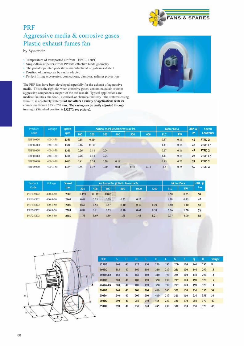
68
PRFAggressive media & corrosive gasesPlastic exhaust fumes fanby Systemair
• Temperature of transported air from –15°C - +70°C• Single-fl ow impellers from PP with effective blade geometry• The powder painted pedestal is manufactured of galvanised steel• Position of casing can be easily adapted• Perfect fi tting accessories: connections, dampers, splinter protection
The PRF fans have been developed especially for the exhaust of aggressive media. This is the right fan when corrosive gases, contaminated air or other aggressive components are part of the exhaust air. Typical applications are medical facilities, the food-, electrical-or chemical industry. The sintered casing from PE is absolutely waterproof and offers a variety of applications with its connectors from ø 125 – 250 mm. The casing can be easily adjusted through turning it (Standard position is LG270, see picture).
Product
Code
Voltage Speed
rpm
Airfl ow m3/s @ Static Pressure Pa. Motor Data dBA @
1m
Speed
Controller100 200 300 400 500 600 FLC kW
PRF160D4 400-3-50 1350 0.18 0.114 0.57 0.16 46 RTRD 2
PRF160E4 230-1-50 1330 0.16 0.101 1.11 0.14 46 RTRE 1.5
PRF180D4 400-3-50 1360 0.26 0.18 0.04 0.57 0.16 49 RTRD 2
PRF180E4 230-1-50 1365 0.26 0.18 0.04 1.11 0.14 49 RTRE 1.5
PRF200D4 400-3-50 1413 0.41 0.35 0.29 0.19 0.95 0.25 59 RTRD 2
PRF250D4 400-3-50 1374 0.85 0.77 0.70 0.61 0.47 0.33 2.5 0.75 66 RTRD 4
PFR A C øD E H L N P Q R Weight
125D2 140 40 125 150 250 195 200 100 140 235 9
160D2 183 40 160 180 310 210 255 100 140 290 13
160D4/E4 183 40 160 180 310 190 255 100 140 290 14
180D2 208 40 180 190 350 230 277 120 190 320 19
180D4/E4 208 40 180 190 350 190 277 120 190 320 14
200D2 240 40 200 200 410 245 320 150 230 355 34
200D4 240 40 200 200 410 210 320 150 230 355 34
250D2 290 40 250 240 495 230 330 170 250 370 49
250D4 290 40 250 240 495 230 330 170 250 370 46
Product
Code
Voltage Speed
rpm
Airfl ow m3/s @ Static Pressure Pa. Motor Data dBA @
1m200 400 600 800 1000 1200 FLC kW
PRF125D2 400-3-50 2806 0.159 0.117 0.067 0.58 0.25 59
PRF160D2 400-3-50 2869 0.41 0.35 0.29 0.22 0.13 1.79 0.75 67
PRF180D2 400-3-50 2700 0.60 0.54 0.47 0.40 0.32 0.20 2.60 1.10 69
PRF200D2 400-3-50 2784 0.88 0.81 0.75 0.70 0.67 0.58 3.26 1.50 74
PRF250D2 400-3-50 2880 1.73 1,69 1.59 1.55 1.45 1.21 7.77 4.00 86
from PE is absolutely waterproof and offers a variety of applications with its connectors from ø 125 – 250 mm. The casing can be easily adjusted through turning it (Standard position is LG270, see picture).
Speed
rpm
Airfl ow m3/s @ Static Pressure Pa. Motor Data dBA @
1m
Speed
Controller100 200 300 400 500 600 FLC kW
1350 0.18 0.114 0.57 0.16 46 RTRD 2
1330 0.16 0.101 1.11 0.14 46 RTRE 1.5
1360 0.26 0.18 0.04 0.57 0.16 49 RTRD 2
1365 0.26 0.18 0.04 1.11 0.14 49 RTRE 1.5
1413 0.41 0.35 0.29 0.19 0.95 0.25 59 RTRD 2
1374 0.85 0.77 0.70 0.61 0.47 0.33 2.5 0.75 66 RTRD 4
PFR A C øD E H L N P Q R Weight
125D2 140 40 125 150 250 195 200 100 140 235 9
160D2 183 40 160 180 310 210 255 100 140 290 13
160D4/E4 183 40 160 180 310 190 255 100 140 290 14
180D2 208 40 180 190 350 230 277 120 190 320 19
180D4/E4 208 40 180 190 350 190 277 120 190 320 14
200D2 240 40 200 200 410 245 320 150 230 355 34
200D4 240 40 200 200 410 210 320 150 230 355 34
250D2 290 40 250 240 495 230 330 170 250 370 49
250D4 290 40 250 240 495 230 330 170 250 370 46
Speed
rpm
Airfl ow m3/s @ Static Pressure Pa. Motor Data dBA @
1m200 400 600 800 1000 1200 FLC kW
2806 0.159 0.117 0.067 0.58 0.25 59
2869 0.41 0.35 0.29 0.22 0.13 1.79 0.75 67
2700 0.60 0.54 0.47 0.40 0.32 0.20 2.60 1.10 69
2784 0.88 0.81 0.75 0.70 0.67 0.58 3.26 1.50 74
2880 1.73 1,69 1.59 1.55 1.45 1.21 7.77 4.00 86

69
DVP Roof plastic fan for aggressive mediaby Systemair
• Temperature of transported air from -15°C to +60°C • Single-fl ow impellers from PP with effective blade geometry• Weather-resistant, sturdy casing made from PP• Motor and terminal box in IP55• Encapsulated motor, outside the airstream
The DVP fans have been developed especially for the exhaust of aggressive media. This is the right fan when corrosive gases, contaminated air or other aggressive components are part of the exhaust air. Typical applications are medical facilities, the food-, electrical-or chemical industry. The casing from PP offers a variety of applications with its connectors from ø 200 - 400 mm. The motor is speed control-lable via frequency converter. Motor protection with protective motor switch to be done on site.
DVP A B C øD E F G H K L M Weight
200D2-4 435 330 200 355 662 200 119 1065 146 30 4x10 25 kg
250D2-4 595 450 250 400 768 250 - 981 181 30 4x12 35 kg
315D4-8 665 535 315 560 810 315 218 1161 200 30 4x12 45 kg
400D4-8L 939 750 400 601 976 400 - 1134 235 30 4x14 55 kg
400D4-8 939 750 400 601 976 400 - 1134 235 30 4x14 55 kg
ProductCode
Voltage Speedrpm
Airfl ow m3/s @ Static Pressure Pa. Motor Data dBA @
4M100 200 300 500 750 1000 1250 FLC kW
DVP200D2-4 400-3-50 2885 0.59 0.56 0.53 0.47 0.36 0.06 2.88 1.714 61.5
DVP250D2-4 400-3-50 2874 1.24 1.19 1.15 1.08 0.91 0.69 0.49 8.56 5.32 69.2
DVP315D4-8 400-3-50 1494 1.14 0.98 0.72 0.33 3.27 0.487 54.6
DVP400D4-8 400-3-50 1445 1.2 1.11 0.98 0.48 0.07 4.12 2.02 59.8
DVP400D4-8-L 400-3-50 1447 1.89 1.62 1.38 0.75 0.53 7.65 4.1 60.5
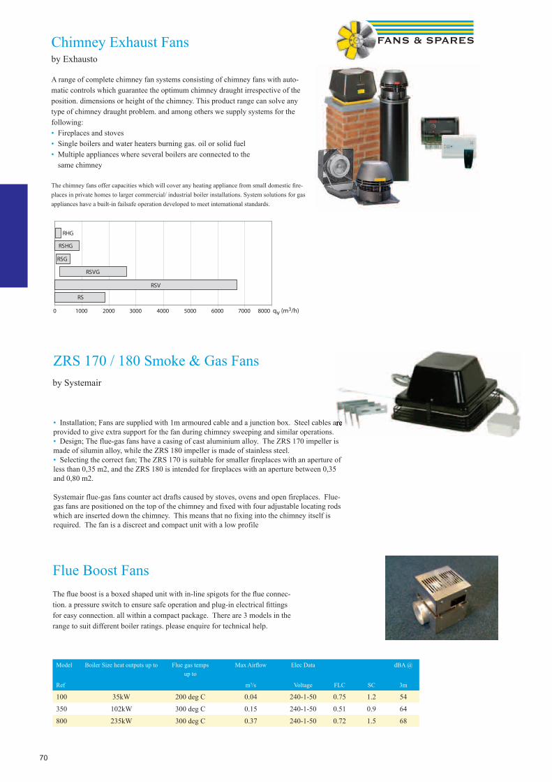
70
Chimney Exhaust Fansby Exhausto
A range of complete chimney fan systems consisting of chimney fans with auto-matic controls which guarantee the optimum chimney draught irrespective of the position. dimensions or height of the chimney. This product range can solve any type of chimney draught problem. and among others we supply systems for the following:• Fireplaces and stoves• Single boilers and water heaters burning gas. oil or solid fuel• Multiple appliances where several boilers are connected to the same chimney
The chimney fans offer capacities which will cover any heating appliance from small domestic fi re-places in private homes to larger commercial/ industrial boiler installations. System solutions for gas appliances have a built-in failsafe operation developed to meet international standards.
qv (m3/h)
Flue Boost FansThe fl ue boost is a boxed shaped unit with in-line spigots for the fl ue connec-tion. a pressure switch to ensure safe operation and plug-in electrical fi ttings for easy connection. all within a compact package. There are 3 models in the range to suit different boiler ratings. please enquire for technical help.
Model Boiler Size heat outputs up to Flue gas temps up to
Max Airfl ow Elec Data dBA @
Ref m3/s Voltage FLC SC 3m
100 35kW 200 deg C 0.04 240-1-50 0.75 1.2 54
350 102kW 300 deg C 0.15 240-1-50 0.51 0.9 64
800 235kW 300 deg C 0.37 240-1-50 0.72 1.5 68
ZRS 170 / 180 Smoke & Gas Fans
• Installation; Fans are supplied with 1m armoured cable and a junction box. Steel cables are provided to give extra support for the fan during chimney sweeping and similar operations.• Design; The flue-gas fans have a casing of cast aluminium alloy. The ZRS 170 impeller is made of silumin alloy, while the ZRS 180 impeller is made of stainless steel.• Selecting the correct fan; The ZRS 170 is suitable for smaller fireplaces with an aperture of less than 0,35 m2, and the ZRS 180 is intended for fireplaces with an aperture between 0,35 and 0,80 m2.
Systemair flue-gas fans counter act drafts caused by stoves, ovens and open fireplaces. Flue-gas fans are positioned on the top of the chimney and fixed with four adjustable locating rods which are inserted down the chimney. This means that no fixing into the chimney itself is required. The fan is a discreet and compact unit with a low profile
Installation; Fans are supplied with 1m armoured cable and a junction box. Steel cables are
by Systemair

71
GBDF / SSDFFlue dilution fansby Airfl ow
A new range of dilution fans including stainless steel versions for enhanced corrosion resistance, which allow fl exible siting of gas boilers rated between 30 kW and 650 kW input upgraded to include a pressure switch fail safe system and an easy to connect mains fl ying lead with snap-in plug and socket, the airfl ow range of fl ue dilution fans is available in 5 sizes to satisfy the dilution needs of industrial and commercial boilers. Each size is available in standard form (GBDF series) for atmospheric boilers and water heaters of circa 75% effi ciency. Enhanced corrosion resistance versions (SSDF series) with stainless steel fan cases are also available for installation where regulations or the specifi cation calls for stainless steel ducting, and, when higher effi ciency boilers such as modular designs are likely to produce condensa-tion. Condensation should not be allowed to collect in the fan casing.
Performance table at 20°CFan Size Airfl ow Litres / Sec @ Pascals Pa Volt FLC
amps
Motor
W
RPM
0 30 60 100 120 160 200 250 275 300 350 375
GBDF2 / SSDF 2 300 260 230 80 0 230 0.64 75 900
GBDF3 / SSDF3 600 550 510 440 380 120 0 230 1.45 120 880
GBDF4 / SSDF4 1000 950 900 815 760 640 340 80 0 230 2.8 335 930
GBDF5 / SSDF5 Not suitable below 90Pa 1370 1324 1200 1075 850 450 200 0 415 2.6 900 940
GBDF6 / SSDF6 Not suitable below 180Pa 1675 1420 1280 1085 625 460 415 2.9 900 900
Typical performance table at 20°CFan Size Units GBDF2 GBDF3 GBDF4 GBDF5 GBDF6
SSDF2 SSDF3 SSDF4 SSDF5 SSDF6
Maximum boiler input rating kW 80 160 270 425 650
Minimum inlet duct diameter mm 254 305 305 457 457
Minimum inlet louvre size mm 300x300 400x400 400x400 600x600 600x600
Minimum discharge duct diameter mm 225 275 345 370 457
Minimum discharge grille size mm 300x300 400x400 450x450 500x500 600x600
Diluted fl ue gas volume l/s 215 430 730 1145 1750
Total static pressure loss in system pa 70 93 130 160 180
Maximum fl ue velocity m/s 5.5 7.3 7.9 10.7 10.7
Fan Size A B C D E F G H I J K L M N P R S
2 218 238 179 200 9.5 402 251 265 78 106 304 335 140 191 260 222 101
3 250 270 236 257 9.5 440 302 302 78 109 359 394 175 222 294 281 109
4 352 384 263 295 9.5 578 302 340 78 141 408 445 194 256 409 321 121
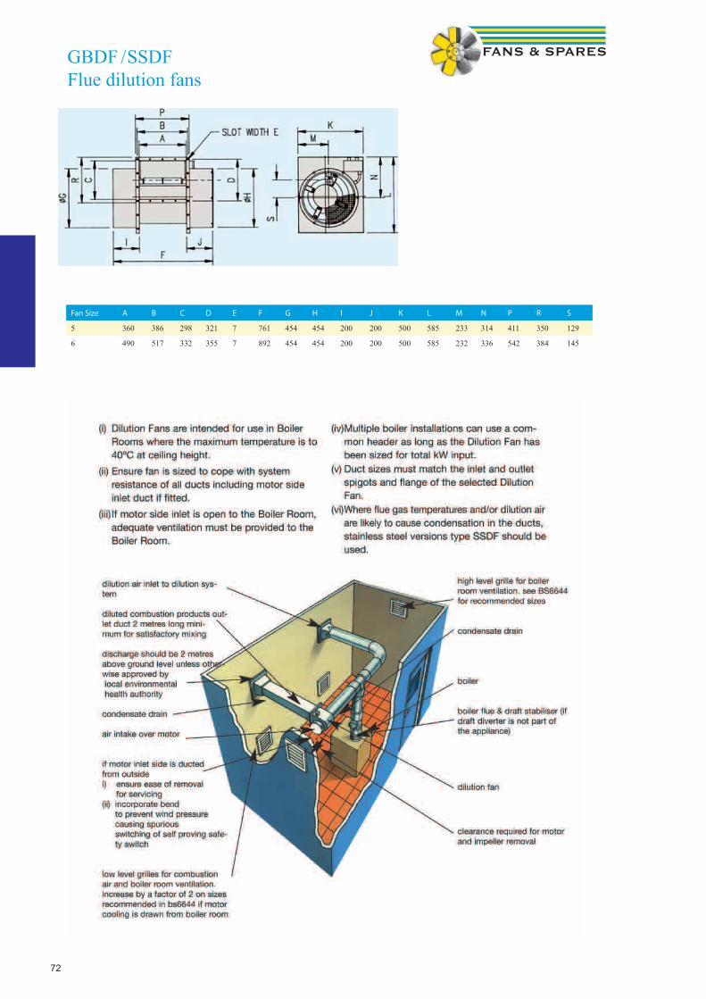
72
Fan Size A B C D E F G H I J K L M N P R S
5 360 386 298 321 7 761 454 454 200 200 500 585 233 314 411 350 129
6 490 517 332 355 7 892 454 454 200 200 500 585 232 336 542 384 145
GBDF / SSDFFlue dilution fans
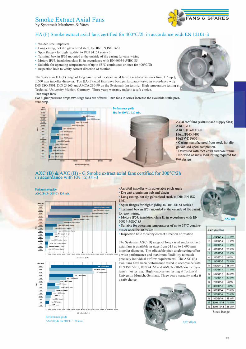
73
AXC (B) & AXC (B) - G Smoke extract axial fans certified for 300°C/2h in accordance with EN 12101-3
• Aerofoil impeller with adjustable pitch angle• Die cast aluminium hub and blades• Long casing, hot dip galvanized steel, to DIN EN ISO 1461• Spun flanges for high rigidity, to DIN 24154 series 3• Terminal box in IP65 mounted at the outside of the casing for easy wiring• Motors IP54, insulation class H, in accordance with EN 60034-5/IEC 85• Suitable for operating temperatures of up to 55°C continu-ous or once for 300°C/2h• Inspection hole to verify correct direction of rotation
The Systemair AXC (B) range of long cased smoke extract axial fans is available in sizes from 315 up to 1.600 mm impeller diameter. The adjustable pitch angle setting offers a wide performance and maximum flexibility to match precisely individual airflow requirements. The AXC (B) axial fans have been performance tested in accordance with DIN ISO 5801, DIN 24163 and AMCA 210-99 on the Sys-temair fan test rig. High temperature testing at Technical University Munich, Germany. Three years warranty make it a safe choice.
AXC (B)-G
AXC (B)
Stock Range
HA (F) Smoke extract axial fans certified for 400°C/2h in accordance with EN 12101-3
• Welded steel impellers• Long casing, hot dip galvanized steel, to DIN EN ISO 1461• Spun flanges for high rigidity, to DIN 24154 series 3• Terminal box in IP65 mounted at the outside of the casing for easy wiring• Motors IP55, insulation class H, in accordance with EN 60034-5/IEC 85• Suitable for operating temperatures of up to 55°C continuous or once for 400°C/2h• Inspection hole to verify correct direction of rotation
The Systemair HA (F) range of long cased smoke extract axial fans is available in sizes from 315 up to1.600 mm impeller diameter. The HA (F) axial fans have been performance tested in accordance withDIN ISO 5801, DIN 24163 and AMCA 210-99 on the Systemair fan test rig. High temperature testing atTechnical University Munich, Germany. Three years warranty make it a safe choice.Two stage fansFor higher pressure drops two stage fans are offered. Two fans in series increase the available static pres-sure drop.
Performance guideHA for 400°C / 120 min.
Performance guideAXC (B) for 300°C / 120 min.
Performance guideAXC (B)-G for 300°C / 120 min.
Axial roof fans (exhaust and supply fans)AXC...-DAXC...(B)-D F300HA...(F)-D F400HABV-D F600• Casing manufactured from steel, hot dip galvanised upon completion.• Delivered with roof cowl and base frame.• No wind or snow load testing required for this design.
Smoke Extract Axial Fansby Systemair Matthews & Yates
HA (F) Smoke extract axial fans certified for 400°C/2h in accordance with EN 12101-3
The Systemair HA (F) range of long cased smoke extract axial fans is available in sizes from 315 up to1.600 mm impeller diameter. The HA (F) axial fans have been performance tested in accordance withDIN ISO 5801, DIN 24163 and AMCA 210-99 on the Systemair fan test rig. High temperature testing at
AXC (B) & AXC (B) - G Smoke extract axial fans certified for 300°C/2h in accordance with EN 12101-3AXC (B) & AXC (B) - G Smoke extract axial fans certified for 300°C/2h in accordance with EN 12101-3AXC (B) & AXC (B) - G Smoke extract axial fans certified for 300°C/2h
• Aerofoil impeller with adjustable pitch angle• Die cast aluminium hub and blades• Long casing, hot dip galvanized steel, to DIN EN ISO 1461• Spun flanges for high rigidity, to DIN 24154 series 3• Terminal box in IP65 mounted at the outside of the casing for easy wiring• Motors IP54, insulation class H, in accordance with EN 60034-5/IEC 85• Suitable for operating temperatures of up to 55°C continu-ous or once for 300°C/2h
Terminal box in IP65 mounted at the outside of the casing
AXC (B)
Technical University Munich, Germany. Three years warranty make it a safe choice.Two stage fansFor higher pressure drops two stage fans are offered. Two fans in series increase the available static pres-sure drop.
Performance guideHA for 400°C / 120 min.
Performance guideAXC (B) for 300°C / 120 min.
Axial roof fans (exhaust and supply fans)Axial roof fans (exhaust and supply fans)AXC...-DAXC...-DAXC...(B)-D F300AXC...(B)-D F300HA...(F)-D F400HA...(F)-D F400HABV-D F600HABV-D F600• Casing manufactured from steel, hot dip • Casing manufactured from steel, hot dip galvanised upon completion.galvanised upon completion.• Delivered with roof cowl and base frame.• Delivered with roof cowl and base frame.• No wind or snow load testing required for • No wind or snow load testing required for this this design.

74
HABV Smoke extract axial fans certified for 600°C/2h in accordance with EN 12101-3
• Welded steel impellers• Long casing, hot dip galvanized steel, to DIN EN ISO 1461, with integrated guide vane• Spun flanges for high rigidity, to DIN 24154 series 3• Terminal box in IP65 mounted at the outside of the casing for easy wiring• Motors IP55, insulation class H, in accordance with EN 60034-5/IEC 85• Motor encapsulated, with cooling duct• Suitable for operating temperatures of up to 55°C continuous or once for 600°C/2h
by Systemair
The Systemair HABV range of long cased smoke extract axial fans is available in sizes from 450 up to 1800 mm impeller diameter. The pitch angle can be individually set before manufacturing and offers a wide performance and flexibility range to precisely match airflow requirements. The HABV axial fans have been performance tested in accordance with DIN ISO 5801, DIN 24163 and AMCA 210-99 on the Systemair fan test rig. High temperature testing at Technical University Munich, Germany. Three years warranty make it a safe choice. HABV axial fan casings are heavy gauge, hot dip galvanized upon completion, with spun flanges for high rigidity. Integrated inlet guide vane. Insulated motor enclosurewith cooling duct for motor cooling.
Performance guideHABV for 600°C 120 min.
Fans & Spares of-fer a full range of smoke extract, car park extract as well as tunnel fans from Systemair as shown. We can also offer similar systems from other manufactur-ers including Soler & Palau, Elta Fans, London Fans & Victoria Fans
High temperature range
Smoke Extract Axial Fans
HABV-GTwo high temperature smoke extract fans mounted in series, same rotational direction. In the case of one fan being switched off or stops running the other fan will supply approx 65% of the total air volume. Resistance figures of up to 2700 pascals can be achieved

75
DVV F400/600 Roof Mounted Smoke Extract Fan
• Smoke extract unit• 400°C / 120 min• Vertical exhaust• Suitable for coastal applications• Wide range of accessories• Certified acc. to EN 12101-3 at TU Munich• CE-certified acc. to EN 12101-3, 2002-06 at TÜV Süd
The DVV smoke extract fans are used in case of fire to extract smoke gases from rooms, and also during normal working conditions for standard ventilation. Smoke-free escape ways increase the chances to rescue people in case of a fire. For installation only over heated rooms.The octagonal casing is manufactured from seawater resistant aluminium. The base frame consist of galvanised steel. The impeller with backward-curved blades is manufactured from galvanised steel. Motor cooling with fresh air via air duct. Thermal motor protection on request. In case of fire all protective devices must be bridged to guarantee functional capability.Available in 6 sizes (400, 450, 560, 630, 800, 1000) over 70 models with duties up to 52,500 m3/h
WVA F400/600 Wall Mounted Smoke Extract Fan
• Smoke extract unit for wall mounting• 400°C / 120 min • Wide range of accessories• Certified acc. to EN 12101-3 at TU Munich• CE-certified acc. to EN 12101-3, 2002-06 at TÜV Süd
The WVA smoke extract fans are used in case of fire to extract smoke gases from rooms, and also for daily ventilation (dual purpose fans). Smoke-free escape ways increase the chances to rescue people in case of fire. For installation only outside the building. Fans are certified for horizontal installation on a wall, mo-tor pointing downwards.The casing is manufactured from steel, powder coated RAL 7032. The base frame consists of galva-nised steel. The impeller with backward-curved blades is manufactured from galvanised steel. Thermal motor protection on request (PTC or thermal contact). In case of fire all protective devices must be bridged to guarantee functional capability.Available in 6 sizes (400, 450, 560, 630, 800, 1000) over 50 models with duties up to 40,000 m3/h
High Temperature Smoke Ventilation Fansby Systemair
75
DVV F400/600 Roof Mounted Smoke Extract FanDVV F400/600 Roof Mounted Smoke Extract FanDVV
• Smoke extract unit• 400°C / 120 min• Vertical exhaust• Suitable for coastal applications• Wide range of accessories• Certified acc. to EN 12101-3 at TU Munich• CE-certified acc. to EN 12101-3, 2002-06 at TÜV Süd
The DVV smoke extract fans are used in case of fire to extract smoke gases from rooms, and also during normal working conditions for standard ventilation. Smoke-free escape ways increase the chances to rescue people in case of a fire. For installation only over heated rooms.The octagonal casing is manufactured from seawater resistant aluminium. The base frame consist of galvanised steel. The impeller with backward-curved blades is manufactured from galvanised steel. Motor cooling with fresh air via air duct. Thermal motor protection on request. In case of fire all protective devices must be bridged to guarantee functional capability.Available in 6 sizes (400, 450, 560, 630, 800, 1000) over 70 models with duties up to 52,500 m3/h
The DVV smoke extract fans are used in case of fire to extract smoke gases from rooms, and also
Smoke-free escape ways increase the chances to rescue people in case of a fire. For installation
The octagonal casing is manufactured from seawater resistant aluminium. The base frame consist
WVA F400/600 Wall Mounted Smoke Extract Fan
• Smoke extract unit for wall mounting• 400°C / 120 min • Wide range of accessories• Certified acc. to EN 12101-3 at TU Munich• CE-certified acc. to EN 12101-3, 2002-06 at TÜV Süd
The WVA smoke extract fans are used in case of fire to extract smoke gases from rooms, and also for The WVA smoke extract fans are used in case of fire to extract smoke gases from rooms, and also for daily ventilation (dual purpose fans). Smoke-free escape ways increase the chances to rescue people daily ventilation (dual purpose fans). Smoke-free escape ways increase the chances to rescue people in case of fire. For installation only outside the building. Fans are certified for horizontal installation on a wall, mo-For installation only outside the building. Fans are certified for horizontal installation on a wall, mo-tor pointing downwards.The casing is manufactured from steel, powder coated RAL 7032. The base frame consists of galva-nised steel. The impeller with backward-curved blades is manufactured from galvanised steel. Thermal motor protection on request (PTC or thermal contact). In case of fire all protective devices must be bridged to guarantee functional capability.Available in 6 sizes (400, 450, 560, 630, 800, 1000) over 50 models with duties up to 40,000 m3/h
High Temperature Smoke Ventilation Fansby Systemair
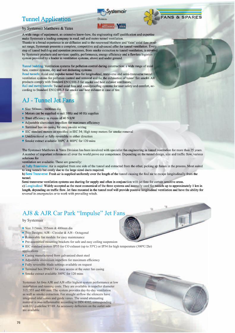
7676
A wide range of equipment, an extensive know-how, the engineering staff qualifi cation and expertise make Systemair a leading company in road, rail and metro tunnel ventilation.Thanks to a broad experience in air diffusion and to the renowned Matthew and Yates’ axial fans prod-uct range, Systemair presents a complete, competitive and advanced offer for tunnel ventilation. Every step of tunnel building and operation processes, from smoke extraction to tunnel ventilation, is covered by Systemair products and services: quality, performance, energy effi ciency and a fl awless logistics system provided by a leader in ventilation systems, above and under ground.
Tunnel building: Ventilation systems for pollution control during construction: a wide range of axial fans, control systems, dry and wet dedusting systems.Road tunnels: Axial and impulse tunnel fans for longitudinal, transverse and semi-transverse tunnel ventilation systems for pollution control and removal and for the exhaustion of tunnel fi re smoke. All products comply with Standard EN12101-3 for smoke and heat exhaust ventilators.Rail and metro tunnels: Tunnel axial fans and soundproofi ng systems for user safety and comfort, ac-cording to Standard EN12101-3 for smoke and heat exhaust in case of fi re.
Tunnel Applicationby Systemair Matthews & Yates
AJ8 & AJR Car Park “Impulse” Jet Fansby Systemair
• Size 315mm, 355mm & 400mm dia• Two Designs; AJR - Circular & AJ8 - Octagonal • Removable fan module for easy maintenance• Pre-assembled mounting brackets for safe and easy ceiling suspension• IEC standard motors IP55 for CO exhaust (up to 55ºC) or IP54 for high temperature (300ºC/2hr) applications• Casing manufactured from galvanized sheet steel• Adjustable aluminium impellers for maximum effi ciency• Fully reversible blade settings available on request• Terminal box IP66/67 for easy access at the outer fan casing• Smoke extract available 300ºC for 120 mins
AJ - Tunnel Jet Fans• Size 500mm - 1600mm dia• Motors can be supplied to suit 50Hz and 60 Hz supplies • Trust effi ciency in excess of 40 N/kW• Adjustable aluminium impellers for maximum effi ciency• Terminal box on casing for easy on-site wiring• IEC standard motors as specifi ed in IEC 34; High temp motors for smoke removal • Unidirectional or fully reversible in either direction• Smoke extract available 300ºC & 400ºC for 120 mins
Systemair Jet fans AJR and AJ8 offer highest system performance at lowinstallation and running costs. They are available in impeller diameter315, 355 and 400 mm. The system provides day-by-day ventilationas well as smoke extraction. For straight airflow the silencers haveintegrated inlet cones and guide vanes. The sound attenuatingmaterial is non-inflammable according to DIN 4102, correspondingwith EU guideline 97/69. As accessory deflectors on the outlet sideare available.
The Systemair Matthews & Yates Division has been involved with specialist fan engineering in tunnel ventilation for more than 25 years.A number of important references all over the world prove our competence. Depending on the tunnel design, size and traffic flow, various solutions forventilation are available. These are generally: a) Fully Transverse: Air is supplied from one side of the tunnel and extracted from the other, picking up fumes in the process. Most suited to long tunnels but costly due to the large sized ducts required.b) Semi Transverse: Fresh air is supplied uniformly over the length of the tunnel causing the foul air to escape longitudinally from the tunnel.Semi transverse ventilation systems use ducting for supply and often in conjunction with jet fans for certain sensitive areas. c) Longitudinal: Widely accepted as the most economical of the three systems and normally used for tunnels up to approximately 1 km in length, depending on traffic flow. Jet fans mounted in the tunnel roof will provide positive longitudinal ventilation and have the ability for reversal in emergencies or to work with prevailing winds.
A wide range of equipment, an extensive know-how, the engineering staff qualifi cation and expertise make Systemair a leading company in road, rail and metro tunnel ventilation.Thanks to a broad experience in air diffusion and to the renowned Matthew and Yates’ axial fans prod-Thanks to a broad experience in air diffusion and to the renowned Matthew and Yates’ axial fans prod-uct range, Systemair presents a complete, competitive and advanced offer for tunnel ventilation. Every uct range, Systemair presents a complete, competitive and advanced offer for tunnel ventilation. Every step of tunnel building and operation processes, from smoke extraction to tunnel ventilation, is covered step of tunnel building and operation processes, from smoke extraction to tunnel ventilation, is covered by Systemair products and services: quality, performance, energy effi ciency and a fl awless logistics by Systemair products and services: quality, performance, energy effi ciency and a fl awless logistics system provided by a leader in ventilation systems, above and under ground.
Tunnel building: Ventilation systems for pollution control during construction: a wide range of axial Ventilation systems for pollution control during construction: a wide range of axial fans, control systems, dry and wet dedusting systems.Road tunnels: Axial and impulse tunnel fans for longitudinal, transverse and semi-transverse tunnel Axial and impulse tunnel fans for longitudinal, transverse and semi-transverse tunnel ventilation systems for pollution control and removal and for the exhaustion of tunnel fi re smoke.ventilation systems for pollution control and removal and for the exhaustion of tunnel fi re smoke. All products comply with Standard EN12101-3 for smoke and heat exhaust ventilators.Rail and metro tunnels: Tunnel axial fans and soundproofi ng systems for user safety and comfort, ac-Tunnel axial fans and soundproofi ng systems for user safety and comfort, ac-cording to Standard EN12101-3 for smoke and heat exhaust in case of fi re.
Tunnel Applicationby Systemair Matthews & Yates
AJ - Tunnel Jet Fans•• Size 500mm - 1600mm dia Size 500mm - 1600mm dia•• Motors can be supplied to suit 50Hz and 60 Hz supplies Motors can be supplied to suit 50Hz and 60 Hz supplies •• Trust effi ciency in excess of 40 N/kW Trust effi ciency in excess of 40 N/kW•• Adjustable aluminium impellers for maximum effi ciency Adjustable aluminium impellers for maximum effi ciency•• Terminal box on casing for easy on-site wiring Terminal box on casing for easy on-site wiring•• IEC standard motors as specifi ed in IEC 34; High temp motors for smoke removal IEC standard motors as specifi ed in IEC 34; High temp motors for smoke removal •• Unidirectional or fully reversible in either direction Unidirectional or fully reversible in either direction•• Smoke extract available 300ºC & 400ºC for 120 mins
The Systemair Matthews & Yates Division has been involved with specialist fan engineering in tunnel ventilation for more than 25 years.A number of important references all over the world prove our competence. Depending on the tunnel design, size and traffic flow, various solutions forventilation are available. These are generally: a) Fully Transverse: Air is supplied from one side of the tunnel and extracted from the other, picking up fumes in the process. Most suited to long tunnels but costly due to the large sized ducts required.b) Semi Transverse: Fresh air is supplied uniformly over the length of the tunnel causing the foul air to escape longitudinally from the tunnel.Semi transverse ventilation systems use ducting for supply and often in conjunction with jet fans for certain sensitive areas. c) Longitudinal: Widely accepted as the most economical of the three systems and normally used for tunnels up to approximately 1 km in length, depending on traffic flow. Jet fans mounted in the tunnel roof will provide positive longitudinal ventilation and have the ability for reversal in emergencies or to work with prevailing winds.

77
On 1st July 2003, the new ATEX directive 94/9/EC (ATEX = Atmospheres Explosibles) became effective. This directive is valid in all EC countries for operational installations in explosion hazardous zones. Examples are petrol stations, battery rooms, painting cabins and the chemical industry. Systemair provides you with helpful information for the selection of a suitable fan. Please bear in mind that manufacturers are responsible only for the appearance and workmanship of the fan. The system user is responsible for the correct system design for a proper operation. Pre-selection depends on the medium to be transported. Each medium has an individual ignition temperature. Systemair explo-sion proof fans comply with temperature classification T3, some units can also be used in T4. The following table shows possible ignition protection classes.
In contrast to standard fans there are special guidelines for explosion proof fans: • Usage of non sparking materials • Motor temperature must not exceed temperature classification T3 • Traceability of the manufacturing process • Overall considerably higher quality demands
Temperature Classifi ca-tion
Ignition temp of different gas mixtures
Maximum surface temperature of electricalequipment
T1 > 450 °C 450 °C
T2 > 300...> 450 °C 300 °C
T3 > 200...> 300 °C 200 °C
T4 > 135...> 200 °C 135 °C
T5 > 100...> 135 °C 100 °C
T6 > 85...> 100 °C 85 °C
EXCentrifugal fan with casing manufacturedfrom silumin. Ex e increased safety. Compactdesign. Available in 230 V and 400 Vexecution. Air volume up to 1180 m³/h.
RVK-EXCircular duct fan with casing manufacturedfrom conducting plastic. Ex e increasedsafety. Speed controllable. Air volume up to 1020 m³/h.
DKEXCentrifugal fan with casing manufacturedfrom galvanised sheet steel with a brassinlet cone. Ex e increased safety. Speed controllable.Air volume up to 5000 m³/h.
KTEXRectangular duct fan with casing manufacturedfrom galvanised sheet steel witha brass inlet cone. Ex e increased safety.Speed controllable. Air volume up to 5000 m³/h.
AW-EXAxial fan with a square plate for wall mounting and an impeller manufactured from galvanised power-coated sheet steel. Size 355 and 420 are approved for temper-ature classification T4. Speed controllable. Air volume up to 11,500 m³/h.
DVEXRoof fan with casing manufactured from sea water resistant aluminium. Ex e increased safety. Speed controllable. Air volume up to 8600 m³/h.
DVV-EXRoof fan with casing manufactured from sea water re-sistant aluminium. Ex e increased safety. Speed control-lable by frequency converter. Delivery with mountedterminal box. Air volume up to 44,000 m³/h.
AXC-EXAxial fan with casing manufactured from hot dip galva-nised steel. Ex e increased safety. Speed controllable by frequency converter. Air volume up to 190,000 m³/h.
AXCBF-EXAxial fan with casing manufactured from hot dip galva-nised steel. Ex e increased safety. Speed controllable by frequency converter.Air volume up to 20,000 m³/h.
Axial fan with a square plate for wall mounting and an
sheet steel. Size 355 and 420 are approved for temper-
In the industry explosion hazardous areas are classified in zones. ATEX classifies the fans in categories, corresponding to the zones. Categories are independent from the substance causing the explosion hazard. The classification in categories (or zones) is related to the temporal appearance (frequency of occurrence) of explosion hazardous atmosphere. Basically the correct zone or category can only be given by the user of the system, after having conducted an analyse regarding the occurrence of explosion hazardous gases or mixtures in the project. The categories or zones do not define the concentration!Category 1 (zone 0) covers areas, where there is a permanent or long lasting occurrence of explosion hazardous atmosphere (more than 1.000 h/year). Example: Inside a fuel tank.Category 2 (zone 1) covers areas, where there is a regular occurrence of explosion hazardous atmosphere (10 – 1.000 h/ year). Example: Filling machine. Category 3 (zone 2) covers areas, where there is a non-regular or short time appearance of explosion hazardous atmosphere (up to 10 h/year). Example: defective gas pipe, accidents.All Systemair explosion proof fans correspond with category II, allowing an application in zone I and zone 2. The last decision has to be made regarding the ignition protection class. All Systemair explosion proof fans correspond to ignition protection class Ex e = increased safety. The following ignition protection classes may be requested. i intrinsic safety, d pressure resistant capsulation, e increased safety, p over pressure capsulation, o oil capsulation, m cast capsulation, q sand capsulation (Ex e IIA T4)The ignition temperature of the medium but also the classification in explosion groups is important. Both classifications have to be considered (II A or II B) when selecting a suitable fan. A good example is hydrogen. Hydrogen is classified in temperature class T1, but in explosion group II C. Hydrogen can not be extracted with a Systemair explosion proof fan.
Atex Fans (Explosive Atmospheres)

7878
Hydroponicsby Fans & Spares
What is Hydroponics?, by its most simple defi nition, is the growing of plants without soil. The plants are supported in an inert media such as clay pebbles or rockwool and are fed nutrient solution. This means that the plants do not have to develop a large root system in order to feed. Soil-based plants divide their energy evenly between growing upwards and growing downwards (root-ing). A hydroponically grown plant expends a greater proportion of its effort growing upwards because all the nutrients it requires are readily available.
Why ventilate your growing area?
Fans & Spares offer the complete ventilation solution from:-
• Supply Fresh Air Fans - HVK’s 100mm dia to 315mm dia see page 27 (as RVK)
• Extract Air Fans - HVK’s 100mm dia to 315mm dia
• Odour Control - Carbon Filters 100mm to 315mm see page 103
• Speed controllers & temperature stats see page 129/130
• Flexible ducting (Acoustic & Standard) 10m lengths see page 118/119
• Ductwork Components - Tee Pieces / Bends / Reducers etc see page 125
• Clips & Clamps see page 137
• Silencers - Flexible & Rigid see page 125
• Air Circulators - Floor or wall mounted see page 107/108/109
Ventilation is one of the most important parts of your growroom setup. It provides your plants with the ideal growing environment and removes stale air that contains moisture from plant transpiration which can cause disease and decay. Correctly ventilating your growing area also removes any unwanted odours from the water tanks etc, excess heat and provides a continuous supply of fresh CO2 - invaluable for your plant development.
The World renown HVK plastic duct fan, manufactured by Systemair Germany (formerly known as Lti Fans). This fan has been developed especially for the hydroponic market and is considered the best money can buy, these low wattage, high output fans are designed to handle both low air volume hobby use and high air volume commercial use. All HVK fans are tested to run 24hours, 7 days, 365 days a year without problems.
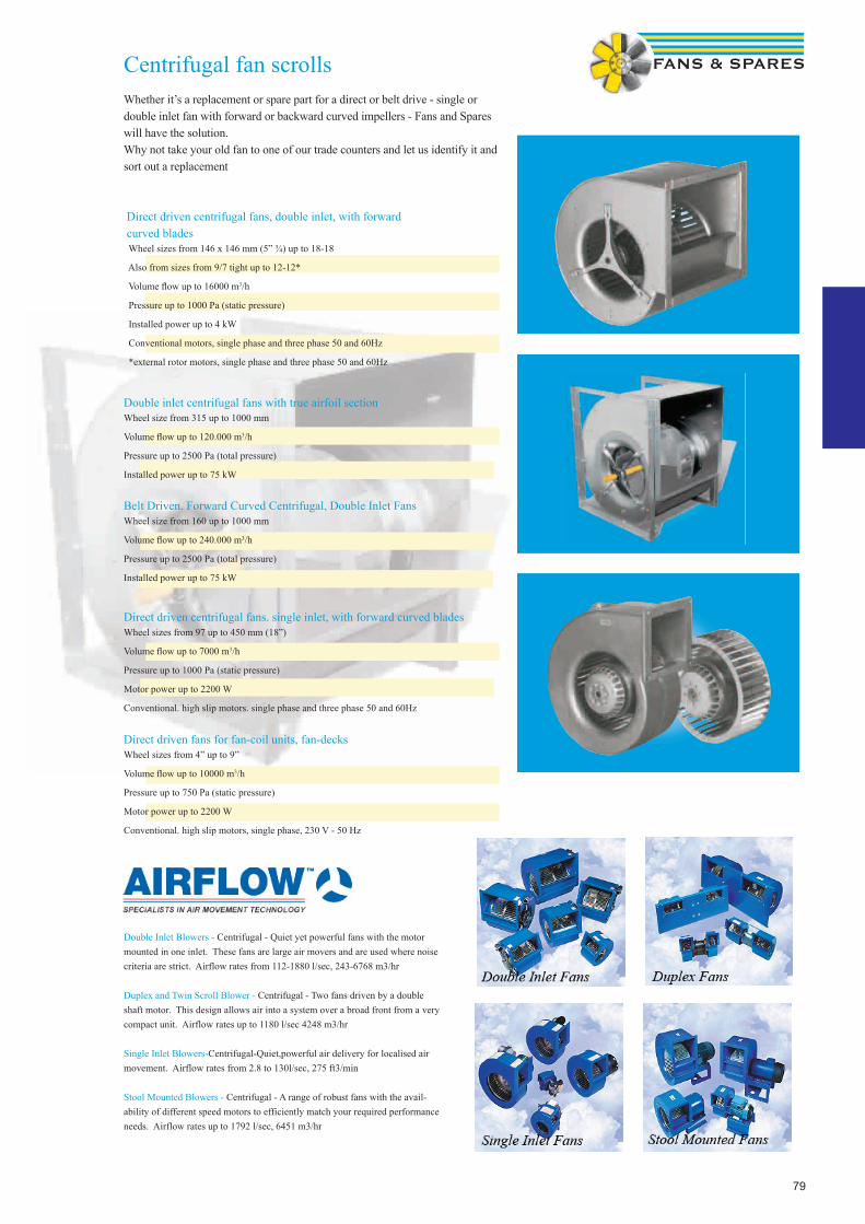
79
Centrifugal fan scrollsWhether it’s a replacement or spare part for a direct or belt drive - single or double inlet fan with forward or backward curved impellers - Fans and Spares will have the solution.Why not take your old fan to one of our trade counters and let us identify it and sort out a replacement
Direct driven centrifugal fans, double inlet, with forward curved blades Wheel sizes from 146 x 146 mm (5” ¾) up to 18-18
Also from sizes from 9/7 tight up to 12-12*
Volume fl ow up to 16000 m3/h
Pressure up to 1000 Pa (static pressure)
Installed power up to 4 kW
Conventional motors, single phase and three phase 50 and 60Hz
*external rotor motors, single phase and three phase 50 and 60Hz
Double inlet centrifugal fans with true airfoil section Wheel size from 315 up to 1000 mm
Volume fl ow up to 120.000 m3/h
Pressure up to 2500 Pa (total pressure)
Installed power up to 75 kW
Belt Driven. Forward Curved Centrifugal, Double Inlet FansWheel size from 160 up to 1000 mm
Volume fl ow up to 240.000 m³/h
Pressure up to 2500 Pa (total pressure)
Installed power up to 75 kW
Direct driven centrifugal fans. single inlet, with forward curved bladesWheel sizes from 97 up to 450 mm (18”)
Volume fl ow up to 7000 m3/h
Pressure up to 1000 Pa (static pressure)
Motor power up to 2200 W
Conventional. high slip motors. single phase and three phase 50 and 60Hz
Direct driven fans for fan-coil units, fan-decksWheel sizes from 4” up to 9”
Volume fl ow up to 10000 m3/h
Pressure up to 750 Pa (static pressure)
Motor power up to 2200 W
Conventional. high slip motors, single phase, 230 V - 50 Hz
Double Inlet Blowers - Centrifugal - Quiet yet powerful fans with the motor mounted in one inlet. These fans are large air movers and are used where noise criteria are strict. Airflow rates from 112-1880 l/sec, 243-6768 m3/hr
Duplex and Twin Scroll Blower - Centrifugal - Two fans driven by a double shaft motor. This design allows air into a system over a broad front from a very compact unit. Airflow rates up to 1180 l/sec 4248 m3/hr
Single Inlet Blowers-Centrifugal-Quiet,powerful air delivery for localised air movement. Airflow rates from 2.8 to 130l/sec, 275 ft3/min
Stool Mounted Blowers - Centrifugal - A range of robust fans with the avail-ability of different speed motors to efficiently match your required performance needs. Airflow rates up to 1792 l/sec, 6451 m3/hr

80
Heat Recovery &Air Handling Units
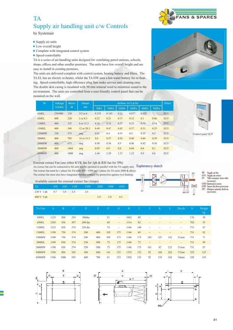
81
TASupply air handling unit c/w Controlsby Systemair
• Supply air units• Low overall height• Complete with integrated control system• Speed-controllableTA is a series of air-handling units designed for ventilating petrol stations, schools, shops, offi ces and other smaller premises. The units have low overall height and are easy to install in existing premises.The units are delivered complete with control system, heating battery and fi lters. The TA EL has an electric re-heater, whilst the TA HW uses a hot-water battery for re-heat-ing. Speed-controllable, high effi ciency plug fans make service and cleaning easy.The double skin casing is insulated with 50 mm mineral wool to minimize sound to the environment. The units are controlled from a user-friendly control panel that can be mounted on the wall.
TA Voltage
V/50Hz
Motor
W
Heater
kW
Airfl ow m3/s @ Pa Filters
50Pa 100Pa 200Pa 300Pa 400Pa 500Pa
450EL 230/400 130 3/3 or 6 0.155 0.143 0.11 0.077 0.025 - EU5
650EL 400 220 5 or 8.3 0.22 0.21 0.17 0.15 0.1 0.06 EU5
1100EL 400 325 8 or 13.3 0.34 0.32 0.27 0.23 0.19 0.14 EU5
1500EL 400 548 12 or 20.3 0.49 0.47 0.42 0.37 0.31 0.25 EU5
1500HW 230 573 enq 0.41 0.4 0.35 0.3 0.25 0.2 EU5
2000EL 400 705 16 or 33.3 0.6 0.57 0.54 0.49 0.44 0.39 EU5
2000HW 400 673 enq 0.56 0.54 0.5 0.46 0.42 0.36 EU5
3000HW 400 1084 enq 0.95 0.9 0.8 0.64 0.4 0.1 EU5
4500HW 400 1880 enq 1.44 1.39 1.27 1.12 0.9 0.6 EU5
External extract Fan (use either KVK fan for 1ph & RSI fan for 3Ph)An extract fan can be connected to the unit and be operated in parallel with the TA supply unit. The extract fan must be 1-phase for TA units 450 - 1500 and 3-phase for TA units 2000 & above. The extract fan must also have integrated thermal contacts for protection against over heating.
Available current for external extract fan (Amps)TA 450 650 1100 1500 2000 3000 4500
230 V 1 ph 0.7 1.0 3.5 2.6
400 V 3 ph 2.8 2.0 4.3
TA Unit A B C D E F G H I J K L Dia dy N Weight kg
450EL 1125 500 354 200dia - 51 - 1042 89 - - - - 176 50
650EL 1203 556 307 200 dia 69 - 1116 82 - - - - 702 55
1100EL 1233 620 374 250 dia 75 - 1146 140 - - - - 731 67
1500EL 1190 750 374 200 400 105 175 1146 69 - - - - 731 82
1500HW 1190 750 374 200 400 105 175 1146 175 102 125 162 21mm 731 71
2000EL 1190 850 374 250 500 73 175 1146 73 - - - - 731 99
2000HW 1190 850 374 250 500 73 175 1146 175 101 92 212 21mm 731 87
3000HW 1296 904 545 300 600 141 152 1252 152 92 160 262 27mm 325 125
4500HW 1346 1006 545 400 700 91 153 1302 153 92 110 362 34mm 320 145
Control panel SCP

82
VXHeat recovery unit c/w Controlsby Systemair
• User friendly controlling by one or several control panels. • Automatic de-frosting for all operating conditions.• Integral filter monitor• EU7 fine filter for supply-air• Cross flow heat exchanger• Inspection covers on both sides• Demand control
VX Unit Air flow m3/s @ Pa
50 Pa 100 Pa 150 Pa 200 Pa 250 Pa 300 Pa
VX400E Supply 0.104 0.1 0.086 0.073 0.058 0.034
Extract 0.123 0.115 0.104 0.093 0.08 0.06
VX700E Supply 0.185 0.173 0.154 0.14 0.12 0.1
Extract 0.235 0.22 0.2 0.185 0.17 0.15
Technical Data VX400E VX700E
Voltage Frequency V/ 50 Hz 230-240 230-240
Input power. Motors Watts 2 x 138 2 x 315
Input power. Heater Battery Watts 1670 2670
Sound power level - Breakout dB(A) 53 59
Mains Fuse Amps 10 16
Weight Kg 47 72
Filter. Supply Air EU7 EU7
Filter. Exhaust Air Aluminium Aluminium
VX400EVX700E
CE Control Panel with plug & play connections that enable control of the fan speed and heater battery temperatures.
The VX-400 E is a complete ventilation unit designed for smaller offices, shops and similar premises. VX 400 E and 700 E are designed to ventilate homes, offices and smaller
commercial buildings.
Fans for supply and extract air, control system, cross flow heat exchanger, thermostat operated pre- and re-heater battery and filters are standard.
Summer block is available as an accessory when heat recovery is not required.
Air flow, supply air temperature and filter change interval are set from one (or several) external mounted control panels type CE. Lamp indicators on the CE panel shows chosen
fans and temperature settings, whether the heating battery is in operation and if filters need to be replaced. The lamps also help to show if any faults would occur.

83
• Duties from 0.05m3/s - 1.9m3/s• Plug and play• Integrated control system • Pre-configured• Very easy to operate• Menu based controller• Factory tested• Low energy use• Ready for demand controlling• Step-less fan speed settings• Step-less differentiation of the fans • Easy maintenance• Manufactured in Aluzinc• Low noise
Topvex TX is an air handling unit with a modern design intended for ventilating offices, day-care centres or used as zone ventilation in larger buildings e.g. schools. To meet the new restricted energy requirements with low SFP (Specific Fan Power) Topvex TX is equipped with EC fan motors. EC-motors consume an average of 30 % less energy than standard alternating current motors. In some applications, the saving can be 50 % or more. Topvex TX with its crossflow heat exchanger is normally used where it is a requirement that the supply and exhaust air must be kept separated. The units have an efficient de-icing function.Ice accretion of the heat exchanger is depending on the outdoor temperature and the humidity in the extract air. The humidity in the extract air is varying a lot depending on what activities it is in the building e.g. an industry premises is normally producing much less humidity than a day-care centre. Therefore has the de-icing function been made settable so that it can be optimized to different applications.The housing is made of insulated panels and has bevelled cast aluminium corners to avoid sharp edges. Doors and panels are made of double-skinned 0.9mm aluzinc with 50mm of internal mineral insulation. Main components are removable with quick release connections for the electrical cables and the large inspection doors facilitate inspection and servicing.Topvex TX is delivered complete with control system, supply and extract filter, cross flow heat exchanger, by-pass damper and Electrical or Hot water heater.The unit is ready configured and therefore very easy to set up, set the Time and date, desired air temperature, fan speed (0-100%) and then program the operating time and the unit is up-and-running.The units have energy saving functions like:- Cool recovering to recover the chilliness in the extract air, when using an external cooling unit. - Demand controlled airflow by using a digital CO2/ humidity sensor or a movement detector.- Sum alarm output that makes it possible for central supervision of many units.-Central supervision secures that incorrect operating, like dirty filters, detects early.
Compact Air handling UnitsTopvex TX / SX (Plate Heat Exc)
Topvex TR / SR (Thermal Wheel)
• Duties from 0.05m3/s - 1.9m3/s• Space saving top connection• Rotating heat exchanger• Integrated control system• Electric or hot water heating coil
Topvex are designed for ventilating schools, day care centres, offices and other smaller premises. The unit is also suitable for zone ventilation in larger buildings. Topvex is delivered complete with control system, rotating wheel, re-heater battery, electric wiring and filters.It is easy to set up the unit. All functions are controlled from a control panel, to be placed on a wall. The unit switches automatically to cool recovery if indoor temperature becomes lower than outside temp.With the rotating heat exchanger, problems with condensation and need for defrost cycles are eliminated.Topvex is tested according to Eurovent EN 1886.
Compact Air handling Units
The Maxi Comfort 800 is controlled by a prepro-grammedcontrol unit with flash memory.It can be used to control up to five units (1master, 4 slaves) automatically or manually.A separate electricity consumption optimisationfunction is integrated, as well as a run time anderror message protocol display.
All information and queries concerning the required mode can be displayed and modified using the cableremote control with LCD display and external keys.Case dimensions: (W x H x D) 156 x 82 x 31 mmThe control panel consists of a control andindicator display with input keys and a real-timeclock. There is also an interface to the motherboard.The standard values and operationalstatus are displayed in cleartext on a four-lineLCD display.The unit can be switched on and off directly onthe control unit.
The Systemair Maxi Comfort 800 is an all-year heat pump including controller. The unit ventilates, cools, heats, regulates supply and exhaust air flows, mixes, filters and savesenergy thanks to its intelligent electronics. Its compact design means that no further installation work is necessary on the unit. It only requires a mains power connection and a connection for thecondensate drain. This allows rapid installation and simple commissioning of the unit, which is tested and ready for service, and only needs to be plugged in.It is also possible to interconnect and operate up to five units in order to cover larger capacity ranges.The typical areas of application of the Maxi Comfort 800 include: Bank branches, petrol stations, offices, boutiques, bakeries, doctors‘ surgeries, residential buildings, and it is also ideal for server rooms.
Maxi Comfort 800

84
VR 400-700DC HEAT RECOVERY UNIT• User friendly controlling by one or several control panels.• Automatic de-frosting for all operating conditions.• Integral filter monitor• EU7 fine filter for supply-air• Thermal Wheel heat recovery• Inspection covers on both sides• Demand control
The VR-400DC & VR-700DC is a complete ventilation unit designed for smaller offices, shops and similar premises, with DC motors for low energy use.Fans for supply and extract air, control system, Thermal Wheel heat exchanger, thermostat operated pre- and re-heater battery and filters are standard.Air flow, supply air temperature and filter change interval are set from one (or several) external mounted control panels type CE.Lamp indicators on the CE panel shows chosen fans and temperature settings, whether the heating battery is in operation and if filters need to be replaced.The lamps also help to show if any faults would occur. A separate timer can be connected for programming day and night operation. A CO2 or presence sensor (potential free contact) can be connected for demand control.
• Rotating heat exchanger• Automatic change normal/summer operation• Rotating heat exchanger• Automatic change normal/summer operation
• Flexible installation without condensate drain• Automatic bypass-function when using a cooker hood
The VR unit is suitable for ventilation of smaller apartments. It is painted white and designed for installation on the wall or ceiling. it is delivered double skinned, fully insulated and with complete control functions, centrifugal fans for supply and extract air, rotating heat exchanger, reheater battery and filter.A duct from the cooker hood can be connected to a separate “bypass-duct” so that the air from the cooker hood leads direct to the exhaust fan and not through the unit.Anti-vibration ceiling mounting brackets and inspection doors on both sides makes the unit easy to place and clean. The unit will automatically alternate between normal operation with heat recovery and summer operation without heat recovery.
Electrical connection• Connection to mains supply via 1 m cable and plug for earthed connection • 4-core (12V) for signal from remote control panel, if installed. Connection via external plug or alternatively on terminal block in the junc-tion box. Use twin plugs for installation of several control panels.• 2-core for potential free signal from separate timer, if installed
VX-700 EV HEAT RECOVERY UNIT
• User friendly controlling by the integrated and/or separate control panel• Automatic de-frosting for all operating conditions• Integral filter monitor• EU7 fine filter for supply-air• Cross flow heat exchanger• Demand control
The VX-700 EV is a complete ventilation unit designed for dwellings, smaller offices, shops and similar premises. It is coated in white enamel and intended for wall mounting in laundry rooms, sculleries or similar locations. Fans for supply and extract air, control system, cross flow heat exchanger, thermostat operated pre- and re-heater battery and filters are standard.Summer block is available as an accessory when heat recovery is not required.Air flow, supply air temperature and filter change interval are set on the integrated control panel and/or from one (or several) external control panels type CE.Lamp indicators on the CE panel shows chosen fans and temperature settings, whether the heating battery is in operation and if filters need to be replaced. The lamps also help to show if any faults would occur. A separate timer can be connected for programming day and night operation. A CO2 or presence sensor (potential free contact) can be connected for demand control. The casing is manufactured from galvanised sheet steel, double skinned with 30 mm of insulation. The VX-700 EV is available in both right-hand (H) and left-hand (V) versions. E.g. for right-hand version (H), the supply air connection is on the top of the unit to the right hand side.
VX 400 EV L HEAT RECOVERY UNITThe VX-400 EV is a complete ventilation unit designed for dwellings, smaller offices, shops and similar premises• User friendly controlling by the integrated and/or separate control panel• Automatic de-frosting for all operating conditions• Integral filter monitor• EU7 fine filter for supply-air• Cross flow heat exchanger• Demand control
VX 250 TV/P HEAT RECOVERY UNITA heat recovery unit equipped with centrifugal fans for supply and extract air, cross flow heat exchanger, thermostat operated re-heater battery and filters.VX 250 TV/P is very easy to install in both new and old dwellings. The unit is designed for in stallation on the wall in laundry room or similar.
VR 250 EH/B HEAT RECOVERY UNIT
Air Handling Units with Heat Recovery(A very small selection of the units available, please enquire for more extensive selections)
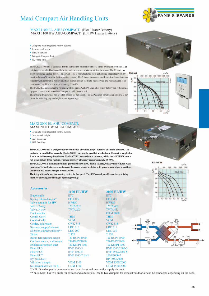
85
• Complete with integrated control system• Low overall height• Easy to service• Integrated bypass duct• EU7 fine filter
The MAXI 1100 unit is designed for the ventilation of smaller offices, shops or similar premises. The unit is to be installed horizontally in the attic, above a corridor or similar locations. The EL unit can also be installed upside down. The MAXI 1100 is manufactured from galvanised sheet steel with 50 mm insulation (30 mm for the inspection covers.) The 2 inspection covers with quick-release fasteners together with removable motors and heat exchange unit facilitate easy service and maintenance. The heat recovery efficiency is approximately 55-65 %.The MAXI EL has an electric re-heater, whilst the MAXI HW uses a hot-water battery for re-heating. A by-pass channel with motorized damper is built into the unit.The integral transformer has a 7-step choice for fan speed. The SCP control panel has an integral 7-day timer for selecting day and night operating settings.
• Complete with integrated control system• Low overall height• Easy to service• EU7 fine filter
The MAXI 2000 unit is designed for the ventilation of offices, shops, nurseries or similar premises. The unit is to be installed horizontally. The MAXI EL can also be installed upside down. The unit is supplied in 2 parts to facilitate easy installation. The MAXI EL has an electric re-heater, whilst the MAXI HW uses a hot-water battery for re-heating. The heat recovery efficiency is approximately 55-65%. The MAXI 2000 is manufactured from galvanised sheet steel, double skinned, with 50 mm of Rock-Wool insulation. To facilitate easy maintenance, the access covers are fitted with quick release clips. In addition, the motors and heat exchanger are removable.The integral transformer has a 4-step choice for fan speed. The SCP control panel has an integral 7-day timer for selecting day and night operating settings.
MAXI 1100 EL AHU-COMPACT, (Elec Heater Battery)MAXI 1100 HW AHU-COMPACT, (LPHW Heater Battery)
MAXI 2000 EL AHU-COMPACT, MAXI 2000 HW AHU-COMPACT
The MAXI 1100 unit is designed for the ventilation of smaller offices, shops or similar premises. The unit is to be installed horizontally in the attic, above a corridor or similar locations. The EL unit can
Maxi Compact Air Handling Units
The MAXI 2000 unit is designed for the ventilation of offices, shops, nurseries or similar premises. The unit is to be installed horizontally. The MAXI EL can also be installed upside down. The unit is supplied in 2 parts to facilitate easy installation. The MAXI EL has an electric re-heater, whilst the MAXI HW uses a hot-water battery for re-heating. The heat recovery efficiency is approximately 55-65%. The MAXI 2000 is manufactured from galvanised sheet steel, double skinned, with 50 mm of Rock-Wool insulation. To facilitate easy maintenance, the access covers are fitted with quick release clips. In addition, the motors and heat exchanger are removable.The integral transformer has a 4-step choice for fan speed. The SCP control panel has an integral 7-day timer for selecting day and night operating settings.
Accessories 1100 EL/HW 2000 EL/HW E-tool cable ETC ETC Spring return damper* EFD 315 EFD 315 Valve actuator for HW HWRO HWRO Valve, 2-way TVTA 202 TVTA 452 Valve, 3-way TVTA 203 TVTA 453 Duct adapter – OKM 2000 Combi-Cowl THM THM Combi-Grille VGM VGM Cooler, cold water CWK 315 CWK 315 Silencer, supply/exhaust LDC 315 LDC 315 Silencer, extract/outdoor** LDC 200 LDC 250 Timer T 120 T 120 Room temperature sensor TG-R5/PT1000 TG-R5/PT1000 Outdoor sensor, wall mount TG-R6/PT1000 TG-R6/PT1000 Exhaust air sensor, duct TG-KH/PT1000 TG-KH/PT1000 Filter EU3 BVF 1100-3 BVF 1500/2000-3 Filter EU5 BVF 1100-5 BVF 1500/2000-5 Filter EU7 BVF 1100-7 BVF 1500/2000-7 By-pass duct – BP 1500/2000 Vibration damper VDM 1100 VDM 1500/2000 Suspension device for EL UDM 1100 UDM 1500/2000 * N.B. One damper to be mounted on the exhaust and one on the supply air duct. ** N.B. Maxi has two ducts for extract and outdoor air. One to two dampers for exhaust/outdoor air can be connected depending on the need.

86
CharacteristicsDV is a range of air handling units, built in modules which gives many design possibilities. It can be built as separate supply air and exhaust air units or as a complete system including heat recovery.The fans are directly driven and the motors are prepared for frequency converters (frequency converters are not included). The DV units in sizes 10-150 are avail-able with centrifugal fans too.The panels are insulated with 50 mm mineral wool that is totally encapsulated between two steel sheet. The selected heavy mineral wool helps to further mini-mize break out of noise from the unit and to good heat insulation.The DV units comes without control system.
Danvent DV Modular Air Handling Units
By Systemair
Sizes and air volumesThe DV Air Handling Unit (AHU) comes in a range of 12different sizes, with air volume capacities from 0,4 -15 m3/sor 1.500 - 54.000 m3/h, making it possible to always findthe unit suitable for any given requirement.FunctionsThe DV AHU features a number of well-dimensioned functions, presenting a choice between different heat exchanger systems, a range of fans, filters, heating and cooling coils and much more. This means the DV AHU can be configured for many different applications, from individual fan units to advanced air handling systems.DampersDV is fitted with contra - rotating dampers in tightness class 3 . The product range consists of shut off - and mixing dampers . Filters Compact filters in class G4 are short pleated filters . Bag filters are available in 5 classes from G3 to F9. Locking rails ensure tightness and easy change of filters . Heat exchangersRotary heat exchangers with a high efficiency level . Possibility for transferring of moisture . Plate heat exchangers for separation of air-flows, and with possibility for corrosion protection . Run - around coil heat exchangers for airflows that are separated from each other.Heating coilsFor heating of air with hot water, steam or electricity. Cooling coilsFor cooling of air with cold water or direct evaporation. FansBelt - driven centrifugal fans with different types of high efficiency fan impellers. Plug fans are direct driven and features low sound levels in the lower frequencies
AHU CasingDV Air Handling Units are built to last.To ensure that the quality of the casing lives up to thehigh standards of its functions, we use panels and frameswhich are protected against corrosion using alu-zinc ofthe highest quality AZ185. Steel sheets which are protected with alu-zinc AZ185, ensure a corrosion protection in class C4 according to EN ISO 12944-2.Frame profiles and cornersDanvent AHUs are constructed using a closed framingprofile with cast aluminium corner pieces. The frame profilesare made of steel with alu-zinc corrosion protection.The result is a strong and robust construction able toresist twisting and lateral movement, making themextremely stable and strong.PanelsThe panels of the DV AHU are built using a sandwichconstruction with 50 mm mineral wool for sound and heatinsulation. The mineral wool is completely encapsulatedbetween two steel sheets. The panels with alu-zinc surface is not only highly corrosion-resistant, but presents an attractive, uniform appear-ance that can last for many years.Disc-LockAn AHU consisting of several sections can be quickly and efficiently assembled using Disc-Lock, our unique assembly system. The sections can be assembled externally or internally as required.
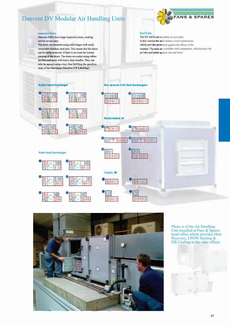
87
Rotary Heat Exchanger
Plate Heat Exchanger
Run-around Coil Heat Exchangers
Recirculated air
Supply air
Inspection DoorsDanvent AHUs have large inspection doors, makingservice access easy.The doors are mounted using solid hinges with easilyremovable stainless steel pins. This means that the doors can be easily removed, if there is no room for normal opening of the doors. The doors are sealed using rubber profiles and locks with heavy-duty handles. They can only be opened using a key, thus fulfilling the specifica-tions of the Machinery Directive (CE Labelling).
Roof UnitsThe DV AHUs are available as roof units.In this version the units feature a roof construction,which provides protection against the effects of theweather. The units are available with components, which protect the air inlet and outlet against rain and snow.
Supply air
Rotary Heat Exchanger Run-around Coil Heat Exchangers
Recirculated air
Inspection DoorsDanvent AHUs have large inspection doors, makingservice access easy.The doors are mounted using solid hinges with easilyremovable stainless steel pins. This means that the doors can be easily removed, if there is no room for normal opening of the doors. The doors are sealed using rubber profiles and locks with heavy-duty handles. They can only be opened using a key, thus fulfilling the specifica-tions of the Machinery Directive (CE Labelling).
Roof UnitsThe DV AHUs are available as roof units.In this version the units feature a roof construction,which provides protection against the effects of theweather. The units are available with components, which protect the air inlet and outlet against rain and snow.
Recirculated air
Danvent DV Modular Air Handling Units
Photo is of the Air Handling Unit installed at Fans & Spares head office which provides Heat Recovery, LPHW Heating & DX Cooling to the sales offices
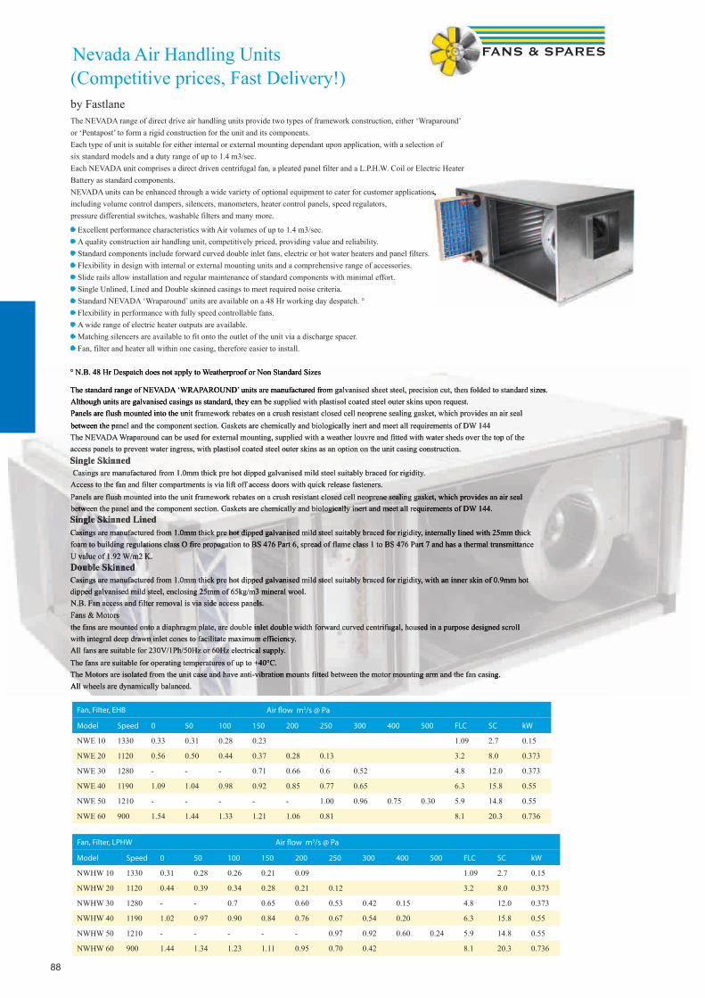
88
The NEVADA range of direct drive air handling units provide two types of framework construction, either ‘Wraparound’or ‘Pentapost’ to form a rigid construction for the unit and its components.Each type of unit is suitable for either internal or external mounting dependant upon application, with a selection ofsix standard models and a duty range of up to 1.4 m3/sec.Each NEVADA unit comprises a direct driven centrifugal fan, a pleated panel filter and a L.P.H.W. Coil or Electric HeaterBattery as standard components.NEVADA units can be enhanced through a wide variety of optional equipment to cater for customer applications, including volume control dampers, silencers, manometers, heater control panels, speed regulators, pressure differential switches, washable filters and many more.
• Excellent performance characteristics with Air volumes of up to 1.4 m3/sec.• A quality construction air handling unit, competitively priced, providing value and reliability.• Standard components include forward curved double inlet fans, electric or hot water heaters and panel filters.• Flexibility in design with internal or external mounting units and a comprehensive range of accessories.• Slide rails allow installation and regular maintenance of standard components with minimal effort.• Single Unlined, Lined and Double skinned casings to meet required noise criteria.• Standard NEVADA ‘Wraparound’ units are available on a 48 Hr working day despatch. °• Flexibility in performance with fully speed controllable fans.• A wide range of electric heater outputs are available.• Matching silencers are available to fit onto the outlet of the unit via a discharge spacer.• Fan, filter and heater all within one casing, therefore easier to install.
° N.B. 48 Hr Despatch does not apply to Weatherproof or Non Standard Sizes
Nevada Air Handling Units (Competitive prices, Fast Delivery!)by Fastlane
The standard range of NEVADA ‘WRAPAROUND’ units are manufactured from galvanised sheet steel, precision cut, then folded to standard sizes.Although units are galvanised casings as standard, they can be supplied with plastisol coated steel outer skins upon request.Panels are flush mounted into the unit framework rebates on a crush resistant closed cell neoprene sealing gasket, which provides an air sealbetween the panel and the component section. Gaskets are chemically and biologically inert and meet all requirements of DW 144The NEVADA Wraparound can be used for external mounting, supplied with a weather louvre and fitted with water sheds over the top of theaccess panels to prevent water ingress, with plastisol coated steel outer skins as an option on the unit casing construction.Single Skinned Casings are manufactured from 1.0mm thick pre hot dipped galvanised mild steel suitably braced for rigidity.Access to the fan and filter compartments is via lift off access doors with quick release fasteners.Panels are flush mounted into the unit framework rebates on a crush resistant closed cell neoprene sealing gasket, which provides an air sealbetween the panel and the component section. Gaskets are chemically and biologically inert and meet all requirements of DW 144.Single Skinned LinedCasings are manufactured from 1.0mm thick pre hot dipped galvanised mild steel suitably braced for rigidity, internally lined with 25mm thickfoam to building regulations class O fire propagation to BS 476 Part 6, spread of flame class 1 to BS 476 Part 7 and has a thermal transmittanceU value of 1.92 W/m2 K.Double SkinnedCasings are manufactured from 1.0mm thick pre hot dipped galvanised mild steel suitably braced for rigidity, with an inner skin of 0.9mm hotdipped galvanised mild steel, enclosing 25mm of 65kg/m3 mineral wool.N.B. Fan access and filter removal is via side access panels.Fans & Motorsthe fans are mounted onto a diaphragm plate, are double inlet double width forward curved centrifugal, housed in a purpose designed scrollwith integral deep drawn inlet cones to facilitate maximum efficiency.All fans are suitable for 230V/1Ph/50Hz or 60Hz electrical supply.The fans are suitable for operating temperatures of up to +40°C.The Motors are isolated from the unit case and have anti-vibration mounts fitted between the motor mounting arm and the fan casing.All wheels are dynamically balanced.
Fan, Filter, EHB Air fl ow m3/s @ Pa
Model Speed 0 50 100 150 200 250 300 400 500 FLC SC kW
NWE 10 1330 0.33 0.31 0.28 0.23 1.09 2.7 0.15
NWE 20 1120 0.56 0.50 0.44 0.37 0.28 0.13 3.2 8.0 0.373
NWE 30 1280 - - - 0.71 0.66 0.6 0.52 4.8 12.0 0.373
NWE 40 1190 1.09 1.04 0.98 0.92 0.85 0.77 0.65 6.3 15.8 0.55
NWE 50 1210 - - - - - 1.00 0.96 0.75 0.30 5.9 14.8 0.55
NWE 60 900 1.54 1.44 1.33 1.21 1.06 0.81 8.1 20.3 0.736
Fan, Filter, LPHW Air fl ow m3/s @ Pa
Model Speed 0 50 100 150 200 250 300 400 500 FLC SC kW
NWHW 10 1330 0.31 0.28 0.26 0.21 0.09 1.09 2.7 0.15
NWHW 20 1120 0.44 0.39 0.34 0.28 0.21 0.12 3.2 8.0 0.373
NWHW 30 1280 - - 0.7 0.65 0.60 0.53 0.42 0.15 4.8 12.0 0.373
NWHW 40 1190 1.02 0.97 0.90 0.84 0.76 0.67 0.54 0.20 6.3 15.8 0.55
NWHW 50 1210 - - - - - 0.97 0.92 0.60 0.24 5.9 14.8 0.55
NWHW 60 900 1.44 1.34 1.23 1.11 0.95 0.70 0.42 8.1 20.3 0.736
NEVADA units can be enhanced through a wide variety of optional equipment to cater for customer applications,
° N.B. 48 Hr Despatch does not apply to Weatherproof or Non Standard Sizes
The standard range of NEVADA ‘WRAPAROUND’ units are manufactured from galvanised sheet steel, precision cut, then folded to standard sizes.Although units are galvanised casings as standard, they can be supplied with plastisol coated steel outer skins upon request.Panels are flush mounted into the unit framework rebates on a crush resistant closed cell neoprene sealing gasket, which provides an air sealbetween the panel and the component section. Gaskets are chemically and biologically inert and meet all requirements of DW 144The NEVADA Wraparound can be used for external mounting, supplied with a weather louvre and fitted with water sheds over the top of theaccess panels to prevent water ingress, with plastisol coated steel outer skins as an option on the unit casing construction.Single Skinned Casings are manufactured from 1.0mm thick pre hot dipped galvanised mild steel suitably braced for rigidity.Access to the fan and filter compartments is via lift off access doors with quick release fasteners.Panels are flush mounted into the unit framework rebates on a crush resistant closed cell neoprene sealing gasket, which provides an air sealbetween the panel and the component section. Gaskets are chemically and biologically inert and meet all requirements of DW 144.Single Skinned LinedCasings are manufactured from 1.0mm thick pre hot dipped galvanised mild steel suitably braced for rigidity, internally lined with 25mm thickfoam to building regulations class O fire propagation to BS 476 Part 6, spread of flame class 1 to BS 476 Part 7 and has a thermal transmittanceU value of 1.92 W/m2 K.Double SkinnedCasings are manufactured from 1.0mm thick pre hot dipped galvanised mild steel suitably braced for rigidity, with an inner skin of 0.9mm hotdipped galvanised mild steel, enclosing 25mm of 65kg/m3 mineral wool.N.B. Fan access and filter removal is via side access panels.Fans & Motorsthe fans are mounted onto a diaphragm plate, are double inlet double width forward curved centrifugal, housed in a purpose designed scrollwith integral deep drawn inlet cones to facilitate maximum efficiency.All fans are suitable for 230V/1Ph/50Hz or 60Hz electrical supply.The fans are suitable for operating temperatures of up to +40°C.The Motors are isolated from the unit case and have anti-vibration mounts fitted between the motor mounting arm and the fan casing.All wheels are dynamically balanced.

89
Grilles. Diffusers& Louvres
Also available, please enquire for the following:
Swirl DiffusersLinear Bar Grilles
Curved Blade GrillesFloor Grilles
Linear Slot DiffusersJet Nozzle DiffusersPerforated Diffusers
Security GrillesFire Rated Air Valves

9090
Pressed steel grillesBy Express-Air
A range of fl ush mounted, non vision grilles and registers pressed out of sheet steel for doors, partitions or wall mounted. Designed for air replace-ment with intumescent fi re blocks or warm air ventilation systems. Sizes available from 100mm to 600mm with 50mm increments on length or height. Standard fi nish is either White RAL 9010 or Silver, with other colour options available on request i.e Black. Free area approx 78%.
Free AreaM2
NominalSize mm
Vel m/sPa
1 1.5 2 2.5 3
3 7 10 15 20
0.017 150 x 150 m3/s 0.02 0.032 0.040 0.051 0.062
200 x 100 NR - - - - 19
0.031 200 x 200 m3/s 0.042 0.060 0.076 0.099 0.150
250 x 150 NR - - - - 19
0.049 250 x 250 m3/s 0.065 0.100 0.127 0.160 0.190
300 x 200 NR - - - - 19
0.07 300 x 300 m3/s 0.09 0.140 0.184 0.225 0.280
450 x 200 NR - - - - 22
0.096 350 x 350 m3/s 0.125 0.180 0.250 0.310 0.380
500 x 250 NR - - - 17 23
0.125 400 x 400 m3/s 0.16 0.250 0.325 0.410 0.500
450 x 300 NR - - - 17 25
0.16 450 x 450 m3/s 0.2 0.310 0.410 0.520 0.620
600 x 350 NR - - 17 21 27
0.2 500 x 500 m3/s 0.25 0.385 0.510 0.650 0.775
600 x 400 NR - 16 21 25 30
0.236 550 x 550 m3/s 0.236 0.354 0.472 0.590 0.708
600 x 500 NR - 18 23 26 35
0.281 600 x 600 m3/s 0.281 0.4215 0.562 0.7025 0.843
700 x 550 NR - 22 26 32 37
How to Order PSG300300S PSR450300W
Type PSG = Pressed Steel Grille PSR = Pressed Steel Register
Size 300300 = 300 x 300 450300 = 450 x 300
Finish S = Satin Anodised W = White (or state RAL code)
For intumescent fi re blocks see page 116
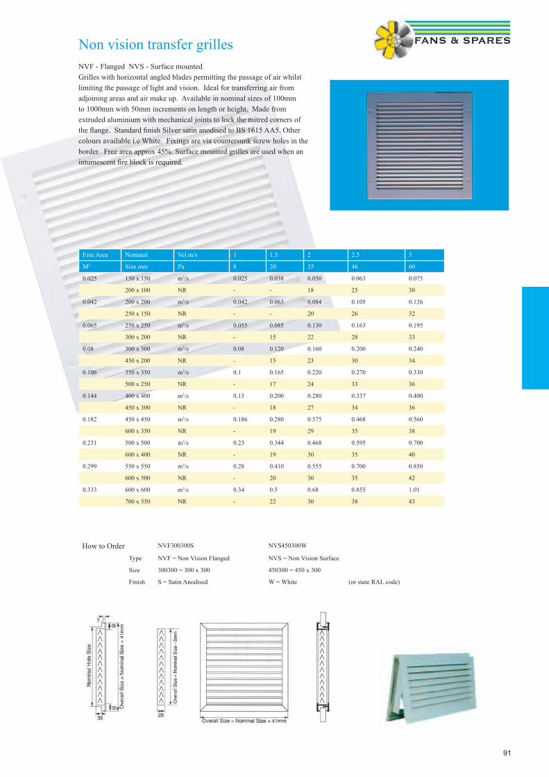
91
Non vision transfer grillesNVF - Flanged NVS - Surface mountedGrilles with horizontal angled blades permitting the passage of air whilst limiting the passage of light and vision. Ideal for transferring air from adjoining areas and air make up. Available in nominal sizes of 100mm to 1000mm with 50mm increments on length or height. Made from extruded aluminium with mechanical joints to lock the mitred corners of the fl ange. Standard fi nish Silver satin anodised to BS 1615 AA5. Other colours available i.e White. Fixings are via countersunk screw holes in the border. Free area approx 45%. Surface mounted grilles are used when an intumescent fi re block is required.
Free Area Nominal Vel m/s 1 1.5 2 2.5 3
M2 Size mm Pa 8 20 35 46 60
0.025 150 x 150 m3/s 0.025 0.038 0.050 0.063 0.075
200 x 100 NR - - 18 25 30
0.042 200 x 200 m3/s 0.042 0.063 0.084 0.105 0.126
250 x 150 NR - - 20 26 32
0.065 250 x 250 m3/s 0.055 0.085 0.130 0.163 0.195
300 x 200 NR - 15 22 28 33
0.08 300 x 300 m3/s 0.08 0.120 0.160 0.200 0.240
450 x 200 NR - 15 23 30 34
0.106 350 x 350 m3/s 0.1 0.165 0.220 0.270 0.330
500 x 250 NR - 17 24 33 36
0.144 400 x 400 m3/s 0.13 0.200 0.280 0.337 0.400
450 x 300 NR - 18 27 34 36
0.182 450 x 450 m3/s 0.186 0.280 0.375 0.468 0.560
600 x 350 NR - 19 29 35 38
0.231 500 x 500 m3/s 0.23 0.344 0.468 0.595 0.700
600 x 400 NR - 19 30 35 40
0.299 550 x 550 m3/s 0.28 0.410 0.555 0.700 0.850
600 x 500 NR - 20 30 35 42
0.333 600 x 600 m3/s 0.34 0.5 0.68 0.855 1.01
700 x 550 NR - 22 30 38 43
How to Order NVF300300S NVS450300W
Type NVF = Non Vision Flanged NVS = Non Vision Surface
Size 300300 = 300 x 300 450300 = 450 x 300
Finish S = Satin Anodised W = White (or state RAL code)
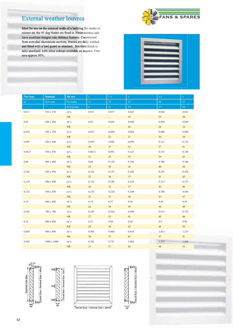
92
External weather louvresIdeal for use on the external walls of a building for intake or extract air, the 45 deg blades are fi xed at 50mm centres and have excellent integral rain defence features. Constructed from extruded aluminium sections, frames are fully welded and fi tted with a bird guard as standard. Standard fi nish is satin anodised. with other colours available on request. Free area approx 50%.
Free Area Nominal Vel m/s 1 1.5 2 2.5 3
m2 Size mm Pa Intake 11 18 34 48 67
Pa Exhaust 6 13 24 37 50
0.011 150 x 150 m3/s 0.011 0.017 0.022 0.028 0.033
NR - - 18 25 30
0.02 200 x 200 m3/s 0.02 0.030 0.040 0.050 0.060
NR - - 20 26 32
0.032 250 x 250 m3/s 0.032 0.048 0.064 0.080 0.096
NR - 25 31 36 38
0.045 300 x 300 m3/s 0.045 0.068 0.090 0.113 0.135
NR 20 27 33 37 41
0.0613 350 x 350 m3/s 0.0613 0.092 0.123 0.153 0.184
NR 21 29 35 39 43
0.08 400 x 400 m3/s 0.08 0.120 0.160 0.200 0.240
NR 22 30 36 40 44
0.102 450 x 450 m3/s 0.102 0.153 0.204 0.255 0.306
NR 22 30 37 41 45
0.125 500 x 500 m3/s 0.125 0.188 0.250 0.313 0.375
NR 24 32 37 42 46
0.152 550 x 550 m3/s 0.152 0.228 0.304 0.380 0.456
NR 25 33 38 43 47
0.18 600 x 600 m3/s 0.18 0.27 0.36 0.45 0.54
NR 26 34 39 44 48
0.245 700 x 700 m3/s 0.245 0.368 0.490 0.613 0.735
NR 27 35 41 45 48
0.32 800 x 800 m3/s 0.32 0.48 0.64 0.8 0.96
NR 28 36 42 46 50
0.405 900 x 900 m3/s 0.405 0.608 0.810 1.013 1.215
NR 30 37 43 47 51
0.502 1000 x 1000 m3/s 0.502 0.753 1.004 1.255 1.506
NR 31 37 44 48 52
External weather louvresIdeal for use on the external walls of a building for intake or extract air, the 45 deg blades are fi xed at 50mm centres and have excellent integral rain defence features. Constructed from extruded aluminium sections, frames are fully welded and fi tted with a bird guard as standard. Standard fi nish is satin anodised. with other colours available on request. Free area approx 50%.
Free Area Nominal Vel m/s

9393
Single & Double Defl ection GrillesBy Express-Air
Part Codes: SDG or DDG
Grilles with either single row or double row of individually adjustable tear-drop section blades and fl anged borders. Supplied with or without an opposed blade damper. Available in nominal sizes of 100mm to 1200mm with 50mm increments on length or height. Made from extruded aluminium with mechani-cal joints to lock the mitred corners of the fl ange. Standard fi nish Silver satin anodised to BS 1615 AA5. Other colours available i.e White. Fixings are via countersunk screw holes in the border. Free area approx 80%. Heavy duty ver-sion and Fixed Blade grilles are available on request.
Free Area Nominal Vel m/s 1.5 2 2.5 3 3.5 4 5
M2 Size mm Pa 5 8 10 15 21 26 38
0.015 150 x 150 m3/s 0.023 0.030 0.038 0.045 0.053 0.060 0.075
Throw M 3.0 4.4 5.4 6.7 7.8 8.8 10.4
NR - - - - 22 25 31
0.034 200 x 200 m3/s 0.051 0.068 0.085 0.102 0.119 0.136 0.170
Throw M 3.6 5.2 6.4 7.7 8.8 9.3 11.0
NR - - 14 21 25 28 35
0.052 250 x 250 m3/s 0.078 0.104 0.130 0.156 0.182 0.208 0.260
Throw M 4.0 5.5 7.0 8.4 9.0 9.9 11.0
NR - - 18 22 27 31 37
0.077 300 x 300 m3/s 0.116 0.154 0.193 0.231 0.270 0.308 0.385
Throw M 4.3 5.6 7.0 8.7 9.7 10.8 12.5
NR - - 18 25 28 32 37
0.105 350 x 350 m3/s 0.158 0.210 0.263 0.315 0.368 0.420 0.525
Throw M 4.5 6.0 7.8 9.5 10.2 11.8 14.0
NR - - 21 26 30 34 41
0.146 400 x 400 m3/s 0.219 0.292 0.365 0.438 0.511 0.584 0.730
Throw M 5.0 6.8 8.6 9.8 11.4 12.7 15.0
NR - 16 23 29 32 36 42
0.18 450 x 450 m3/s 0.270 0.360 0.450 0.540 0.630 0.720 0.900
Throw M 5.5 7.5 9.0 10.6 12.0 14.2 16.7
NR - 18 24 31 35 39 44
0.23 500 x 500 m3/s 0.345 0.460 0.575 0.690 0.805 0.920 1.150
Throw M 6.0 7.9 9.8 11.4 13.2 15.0 18.2
NR - 20 27 31 35 40 46
0.32 600 x 600 m3/s 0.480 0.640 0.800 0.960 1.120 1.280 1.600
Throw M 6.5 9.0 10.3 12.6 14.7 16.7 20.0
NR - 22 29 33 38 42 49
How to Order SDG300300S DDG450350W Type SDG = Single Defl ection DDG = Double Defl ection Size 300300 = 300 x 300 450350 = 450 x 350 Finish S = Satin Anodised W = White (or state RAL code)
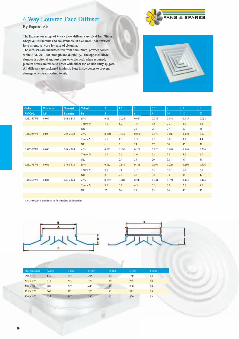
9494
4 Way Louvred Face DiffuserBy Express-Air
The Express-air range of 4 way blow diffusers are ideal for Offi ces, Shops & Restaurants and are available in fi ve sizes. All diffusers have a removal core for ease of cleaning. The diffusers are manufactured from aluminium, powder coated white RAL 9010 for strength and durability. The opposed blade damper is optional and just clips onto the neck when required, plenum boxes are made to order with either top or side entry spigots. All diffusers are packaged in plastic bags inside boxes to prevent damage when transporting to site.
Order Free Area Nominal Vel m/s 2 2.5 3 3.5 4 5 6
Ref Code M2 Size mm Pa 3 4 6 8 10 15 22
EAD150WF 0.009 148 x 148 m3/s 0.018 0.023 0.027 0.032 0.036 0.045 0.054
Throw M 1.0 1.2 1.6 1.8 2.2 2.7 3.2
NR - - 22 25 27 32 36
EAD225WF 0.02 223 x 223 m3/s 0.040 0.050 0.060 0.070 0.080 0.100 0.12
Throw M 1.5 1.9 2.3 2.7 3.0 3.7 4.4
NR - 21 24 27 30 35 38
EAD300WF 0.036 298 x 298 m3/s 0.072 0.090 0.108 0.126 0.144 0.180 0.216
Throw M 2.0 2.5 3.0 3.4 3.9 5.0 6.0
NR - 23 26 29 32 37 41
EAD375WF 0.056 373 x 373 m3/s 0.112 0.140 0.168 0.196 0.224 0.280 0.336
Throw M 2.5 3.1 3.7 4.3 4.9 6.2 7.5
NR 20 24 28 32 34 38 42
EAD450WF 0.081 448 x 448 m3/s 0.162 0.203 0.243 0.284 0.324 0.405 0.486
Throw M 3.0 3.7 4.5 5.3 6.0 7.5 9.0
NR 22 26 29 33 36 40 43
EAD450WF is designed to fi t standard ceiling tiles
Std. Size mm A mm B mm C mm D mm E mm F mm
150 X 150 135 147 295 42 150 83
225 X 225 210 223 370 42 225 83
300 X 300 285 297 445 42 300 83
375 X 375 360 372 520 42 375 83
450 X 450 435 447 595 42 450 83
4 Way Louvred Face DiffuserBy Express-Air
The Express-air range of 4 way blow diffusers are ideal for Offi ces, Shops & Restaurants and are available in fi ve sizes. All diffusers have a removal core for ease of cleaning. The diffusers are manufactured from aluminium, powder coated white RAL 9010 for strength and durability. The opposed blade damper is optional and just clips onto the neck when required, plenum boxes are made to order with either top or side entry spigots. All diffusers are packaged in plastic bags inside boxes to prevent damage when transporting to site.
Order Free Area Nominal Vel m/s 2 2.5 3
Ref Code M2 Size mm Pa 3 4 6

95
Circular Multi Cone Diffuser
Horizontal Air Pattern Vertical Air Pattern
Konika-A-160 m3/s 0.075 0.094 0.112 Konika-A-160 m3/s 0.060 0.075 0.090
dB(A) 25 33 40 dB(A) 25 33 40
Throw m 4.5 5.5 6 Throw m 7 9 10.5
Pa 17.0 27.0 37 Pa 20 34 45.0
Konika-A-200 m3/s 0.128 0.165 0.190 Konika-A-200 m3/s 0.100 0.120 0.145
dB(A) 25 33 40 dB(A) 25 33 40
Throw m 6 7 8 Throw m 8 11 13.5
Pa 14 23 30 Pa 19 30 41
Konika-A-250 m3/s 0.190 0.240 0.275 Konika-A-250 m3/s 0.150 0.190 0.230
dB(A) 25 33 40 dB(A) 25 33 40
Throw m 7 9 10 Throw m 10 12.5 14.5
Pa 12 19 25 Pa 14 23 32
Konika-A-315 m3/s 0.255 0.320 0.375 Konika-A-315 m3/s 0.210 0.275 0.325
dB(A) 25 33 40 dB(A) 25 33 40
Throw m 8 9.5 11 Throw m 11 14 16
Pa 12 18 25 Pa 13 23 30
Konika-A-400 m3/s 0.440 0.560 0.650 Konika-A-400 m3/s 0.370 0.475 0.550
dB(A) 25 33 40 dB(A) 25 33 40
Throw m 11 14 16 Throw m 15 18 21
Pa 11 18 24 Pa 12 21 27
Konika-A-500 m3/s 0.680 0.840 0.980 Konika-A-500 m3/s 0.530 0.660 0.780
dB(A) 25 33 40 dB(A) 25 33 40
Throw m 12.5 16 19 Throw m 17 20 23
Pa 10 15 21 Pa 10 16 22
A Dia B Dia C D Dia E F G H
Konika-A-160 279 323 12 160 22 85 46 35
Konika-A-200 375 428 10 200 26 101 55 51
Konika-A-250 467 538 14 250 33 117 68 67
Konika-A-315 557 635 10 315 42 135 80 85
Konika-A-400 740 856 14 400 49 166 92 116
Konika-A-500 924 1081 17 500 72 199 116 149
Vertical distribution patternHorizontal distribution pattern
Systemair Konika circular ceiling diffuser, with PER plenum box as an acces-sory.
The Konika is a supply and exhaust air diffuser for ceiling assembly. The Konika is suitable for offices, shops or similar premises. The Konika can be connected directly to a circular duct by the use of Konika bar. The Konika is suitable both for cool and warm air. The Konika has high induction which allows a maximum air temperature difference of dT 12 K.The Konika is manufactured from steel with a white powder-coated finish (RAL 9010) and is available in the following sizes: ø 160, ø 200, ø 250 and ø 315. This device can be used for exhaust air.Correct adjustment requires a length of straight duct, 4 times the duct diameter in front of the PER plenum box. Between the PER plenum box and the Konika diffuser there need to be a length of straight duct, 1 times the duct diameter.
95
D Dia E F G H
160 22 85 46 35
200 26 101 55 51
250 33 117 68 67
315 42 135 80 85
400 49 166 92 116
500 72 199 116 149
Vertical distribution pattern

96
Egg Crate Grillesby Express-air
Egg Crate Grilles are the latest addition to the Express-air Product Range. Egg Crate Grilles are designed for use in exhaust or return air situations and may be mounted in walls or ceilings. Made fully out of Alu-minium, the Grille has outer frame manufactured from heavy extrusion which can accommodate the egg crate core. Grilles upto 600 mm x 600 mm are available, which can be mounted effi ciently in the ceilings. The Grille core has a standard ½” x ½” x ½” Egg Crate Size. The free area of the grille is >90% of the nominal area. providing maximum air fl ow and very low noise levels. Egg Crate Grilles can also be supplied as plain cores according to customer’s needs. Standard fi n-ish is Egg Shell White colour – RAL 9010. Can be supplied in other colours as per the requirement of the customers.
OrderRef Code
Free AreaM2
NeckSize mm
Vel m/s 1.5 2 2.5 3 3.5 4 5
Pa 4 6 9 13 18 23 34
ECG100WF 0.009 100 x 100 m3/s 0.014 0.018 0.023 0.027 0.032 0.036 0.045
NR - - - - 22 25 31
ECG150WF 0.019 150 x 150 m3/s 0.029 0.038 0.048 0.057 0.067 0.076 0.095
NR - - - - 22 25 31
ECG200WF 0.034 200 x 200 m3/s 0.051 0.068 0.085 0.102 0.119 0.136 0.170
NR - - - 18 25 28 35
ECG250WF 0.054 250 x 250 m3/s 0.081 0.108 0.135 0.162 0.189 0.216 0.270
NR - - - 19 26 28 37
ECG300WF 0.078 300 x 300 m3/s 0.117 0.156 0.195 0.234 0.273 0.312 0.390
NR - - 16 20 28 32 40
ECG350WF 0.106 350 x 350 m3/s 0.159 0.212 0.265 0.318 0.371 0.424 0.530
NR - - 17 23 30 32 42
ECG400WF 0.144 400 x 400 m3/s 0.216 0.288 0.360 0.432 0.504 0.576 0.720
NR - - 19 24 29 33 43
ECG450WF 0.182 450 x 450 m3/s 0.273 0.364 0.455 0.546 0.637 0.728 0.910
NR - - 20 25 33 35 45
ECG500WF 0.231 500 x 500 m3/s 0.347 0.462 0.578 0.693 0.809 0.924 1.155
NR - - 21 26 33 36 46
ECG595WF 0.299 550 x 550 m3/s 0.449 0.598 0.748 0.897 1.047 1.196 1.495
NR - - 22 28 34 38 50
Opposed blade dampers are available for all sizes of Egg crate grilles, please quote ref EAOBD*** (*** neck size)Plenum boxes with either side or top entry made to order - please specify duct diameter
GAR Egg Crate GrillesBy Systemair
The GAR is an exhaust air grille with fixed deflectors. The GAR is used to evacuate large amounts of air with a minimum pressure drop and has a low sound level.The GAR can be mounted into a wall, a duct sleeve coupling or PRG plenumbox. Available in nine sizes from 200x100 to 600x200.Manufactured from powder-coated aluminium (white RAL 9010) and fitted with friction springs for easy installation.The grille is installed in the duct or wall with the GSF mounting frame. It can also be easily mounted onto the PRG plenumbox.
GSF Mounting Frame GSS Damper PRG Plenum
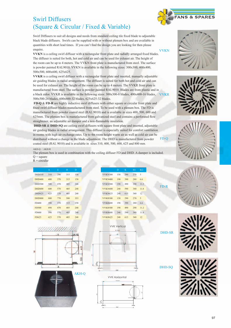
97
Swirl Diffusers(Square & Circular / Fixed & Variable)Swirl Diffusers to suit all designs and needs from standard ceiling tile fi xed blade to adjustable black blade diffusers. Swirls can be supplied with or without plenum box and are available in quantities with short lead times. If you can’t fi nd the design you are looking for then please enquire.VVKN is a ceiling swirl diffuser with a rectangular front plate and radially arranged fi xed blades. The diffuser is suited for both, hot and cold air and can be used for exhaust air. The height of the room can be up to 4 meters. The VVKN front plate is manufactured from steel. The surface is powder painted RAL9010. VVKN is available in the following sizes: 300x300, 400x400, 500x500, 600x600, 625x625.VVKR is a ceiling swirl diffuser with a rectangular front plate and inserted, manually adjustable air guiding blades in radial arrangement. The diffuser is suited for both hot and cold air and can be used for exhaust air. The height of the room can be up to 4 meters. The VVKR front plate is manufactured from steel. The surface is powder painted RAL9010. Blades are from plastic and in a black color. VVKR is available in the following sizes: 300x300-8 blades, 400x400-16 blades, 500x500-24 blades, 600x600-32 blades, 625x625-32 blades. FD-Q & FD-R are highly inductive swirl diffusers with either square or circular front plate and fi xed swirl diffuser blades manufactured from steel. To be used with a plenum box. The FD is manufactured from powder coated steel (RAL 9010) and is available in sizes 400, 500, 600 and 625mm. The plenum box is manufactured from galvanized steel and contains a perforated fl ow straightener, an adjustable air damper and a non-fl ammable insulation. DHD-SR & DHD-SQ are ceiling swirl diffusers with square front plate and inserted, adjustable air guiding blades in radial arrangement. This diffuser is especially suited for comfort ventilation in rooms with high air exchange rates. Up to 4m room height warm air as well as cold air can be distributed without a change in the blade adjustment. The DHD is manufactured from powder coated steel (RAL 9010) and is available in sizes 310, 400, 500, 600, 625 and 800 mm.
VVKN
VVKR
FD-Q
FD-R
DHD-SR
DHD-SQ
AKH-Q / AKH-R
The plenum box is used in combination with the ceiling diffuser FD and DHD. A damper is included. Q = squareR = circular
A E H D
DHD310 310 290 315 158
DHD400 400 370 315 158
DHD500 500 470 405 248
DHD600 600 570 405 248
DHD625 625 570 405 248
DHD800 800 770 500 353
FD400 398 370 315 158
FD500 498 470 405 248
FD600 598 570 405 248
FD625 623 570 405 248
AKH-Q
VVK Vertical
VVK Horizontal
D K H1 KG
VVKN300 158 290 270 5
VVKN400 198 390 280 6.6
VVKN500 198 490 290 11.2
VVKN600 248 590 340 11.8
VVKN625 248 615 340 12
VVKR300 158 290 270 5
VVKR400 198 390 280 6.6
VVKR500 198 490 290 11.2
VVKR600 248 590 340 11.8
VVKR625 248 615 340 12
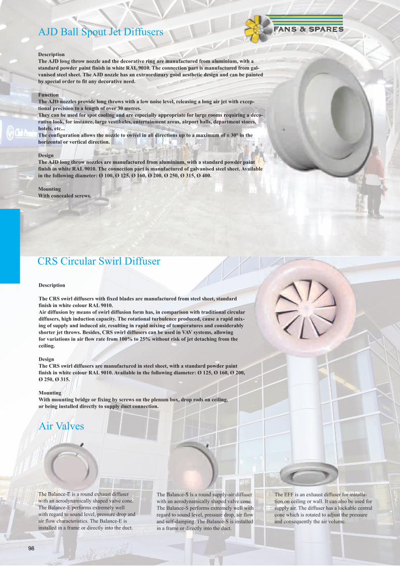
9898
DescriptionThe AJD long throw nozzle and the decorative ring are manufactured from aluminium, with a standard powder paint finish in white RAL 9010. The connection part is manufactured from gal-vanised steel sheet. The AJD nozzle has an extraordinary good aesthetic design and can be painted by special order to fit any decorative need.
FunctionThe AJD nozzles provide long throws with a low noise level, releasing a long air jet with excep-tional precision to a length of over 30 metres.They can be used for spot cooling and are especially appropriate for large rooms requiring a deco-rative look, for instance, large vestibules, entertainment areas, airport halls, department stores, hotels, etc...The configuration allows the nozzle to swivel in all directions up to a maximum of ± 30° in the horizontal or vertical direction.
DesignThe AJD long throw nozzles are manufactured from aluminium, with a standard powder paint finish in white RAL 9010. The connection part is manufactured of galvanised steel sheet. Available in the following diameter: Ø 100, Ø 125, Ø 160, Ø 200, Ø 250, Ø 315, Ø 400.
MountingWith concealed screws.
AJD Ball Spout Jet Diffusers
CRS Circular Swirl Diffuser
Description
The CRS swirl diffusers with fixed blades are manufactured from steel sheet, standard finish in white colour RAL 9010. Air diffusion by means of swirl diffusion form has, in comparison with traditional circular diffusers, high induction capacity. The rotational turbulence produced, cause a rapid mix-ing of supply and induced air, resulting in rapid mixing of temperatures and considerably shorter jet throws. Besides, CRS swirl diffusers can be used in VAV systems, allowing for variations in air flow rate from 100% to 25% without risk of jet detaching from the ceiling.
DesignThe CRS swirl diffusers are manufactured in steel sheet, with a standard powder paint finish in white colour RAL 9010. Available in the following diameter: Ø 125, Ø 160, Ø 200, Ø 250, Ø 315.
MountingWith mounting bridge or fixing by screws on the plenum box, drop rods on ceiling,or being installed directly to supply duct connection.
The Balance-E is a round exhaust diffuser with an aerodynamically shaped valve cone. The Balance-E performs extremely well with regard to sound level, pressure drop and air flow characteristics. The Balance-E is installed in a frame or directly into the duct.
The Balance-S is a round supply-air diffuser with an aerodynamically shaped valve cone. The Balance-S performs extremely well with regard to sound level, pressure drop, air flow and self-damping. The Balance-S is installed in a frame or directly into the duct.
The EFF is an exhaust diffuser for installa-tion on ceiling or wall. It can also be used for supply air. The diffuser has a lockable central cone which is rotated to adjust the pressure and consequently the air volume.
The Balance-E is a round exhaust diffuser The Balance-S is a round supply-air diffuser
Air Valves

99
Spigot / Plenum Boxes
Spigot boxes are made to order from Fans & Spares to suit all grilles, diffusers and Louvre neck sizes. Top entry or Side entry, return edge or shallow pan adapters, the choice is yours. Stan-dard sizes are available from stock, with all others usually 3 to 5 days delivery.
Order Ref:- SBX450450250TE
SBX - Spigot Box (Metal)450450 - Neck Size250 - Duct Connection DiameterTE - Top Entry or SE - Side Entry
Plastic Spigot Boxes are also available, please enquire.
Please enquire for the following Air Distribution Products, also available
from Fans & Spares
Linear Slot Diffusers Fixed Blade Grilles
Floor Grilles Drum Jet DiffusersExposed Duct Diffusers Sinus Nozzle Diffusers
Perforated DiffusersBathroom PIR Damper Plastic Grilles & Diffusers Fire Rated Air Valves
Linear Slot Diffusers
Floor Grilles
Fabricated Ducting Made to Order
Need something out of the ordinary, if it’s to do with air then let Fans & Spares sort it out for you. It’s not just plenum boxes we do, transformation pieces for ducting, kitchen hoods, filter frames, whatever the need just give your local branch a call.
“We make it easy”
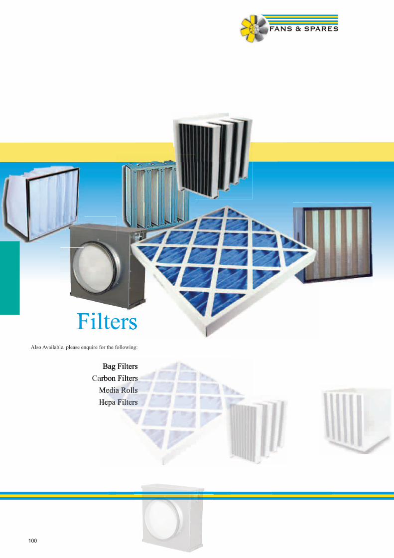
100
FiltersAlso Available, please enquire for the following:
Bag FiltersCarbon Filters
Media RollsHepa Filters
FiltersFiltersFilters
Bag FiltersCarbon Filters
Media RollsHepa Filters
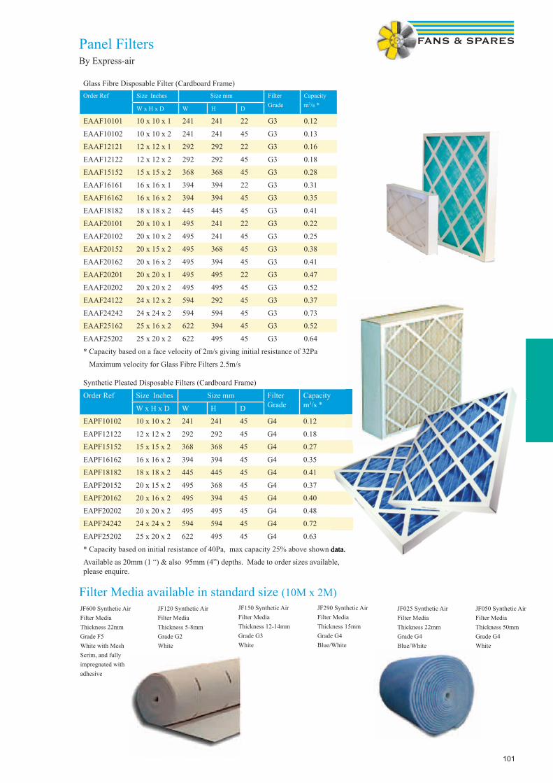
101
Panel FiltersBy Express-air
Glass Fibre Disposable Filter (Cardboard Frame)Order Ref Size Inches Size mm Filter
GradeCapacitym3/s *W x H x D W H D
EAAF10101 10 x 10 x 1 241 241 22 G3 0.12
EAAF10102 10 x 10 x 2 241 241 45 G3 0.13
EAAF12121 12 x 12 x 1 292 292 22 G3 0.16
EAAF12122 12 x 12 x 2 292 292 45 G3 0.18
EAAF15152 15 x 15 x 2 368 368 45 G3 0.28
EAAF16161 16 x 16 x 1 394 394 22 G3 0.31
EAAF16162 16 x 16 x 2 394 394 45 G3 0.35
EAAF18182 18 x 18 x 2 445 445 45 G3 0.41
EAAF20101 20 x 10 x 1 495 241 22 G3 0.22
EAAF20102 20 x 10 x 2 495 241 45 G3 0.25
EAAF20152 20 x 15 x 2 495 368 45 G3 0.38
EAAF20162 20 x 16 x 2 495 394 45 G3 0.41
EAAF20201 20 x 20 x 1 495 495 22 G3 0.47
EAAF20202 20 x 20 x 2 495 495 45 G3 0.52
EAAF24122 24 x 12 x 2 594 292 45 G3 0.37
EAAF24242 24 x 24 x 2 594 594 45 G3 0.73
EAAF25162 25 x 16 x 2 622 394 45 G3 0.52
EAAF25202 25 x 20 x 2 622 495 45 G3 0.64
* Capacity based on a face velocity of 2m/s giving initial resistance of 32Pa
Maximum velocity for Glass Fibre Filters 2.5m/s
Synthetic Pleated Disposable Filters (Cardboard Frame)
Order Ref Size Inches Size mm FilterGrade
Capacitym3/s *W x H x D W H D
EAPF10102 10 x 10 x 2 241 241 45 G4 0.12
EAPF12122 12 x 12 x 2 292 292 45 G4 0.18
EAPF15152 15 x 15 x 2 368 368 45 G4 0.27
EAPF16162 16 x 16 x 2 394 394 45 G4 0.35
EAPF18182 18 x 18 x 2 445 445 45 G4 0.41
EAPF20152 20 x 15 x 2 495 368 45 G4 0.37
EAPF20162 20 x 16 x 2 495 394 45 G4 0.40
EAPF20202 20 x 20 x 2 495 495 45 G4 0.48
EAPF24242 24 x 24 x 2 594 594 45 G4 0.72
EAPF25202 25 x 20 x 2 622 495 45 G4 0.63
* Capacity based on initial resistance of 40Pa, max capacity 25% above shown data.
Available as 20mm (1 “) & also 95mm (4”) depths. Made to order sizes available, please enquire.
JF600 Synthetic Air Filter MediaThickness 22mmGrade F5White with Mesh Scrim, and fully impregnated with adhesive
JF120 Synthetic Air Filter MediaThickness 5-8mmGrade G2White
JF150 Synthetic Air Filter MediaThickness 12-14mmGrade G3White
JF290 Synthetic Air Filter MediaThickness 15mmGrade G4Blue/White
JF025 Synthetic Air Filter MediaThickness 22mmGrade G4Blue/White
JF050 Synthetic Air Filter MediaThickness 50mmGrade G4White
Filter Media available in standard size (10M x 2M)
* Capacity based on initial resistance of 40Pa, max capacity 25% above shown data.
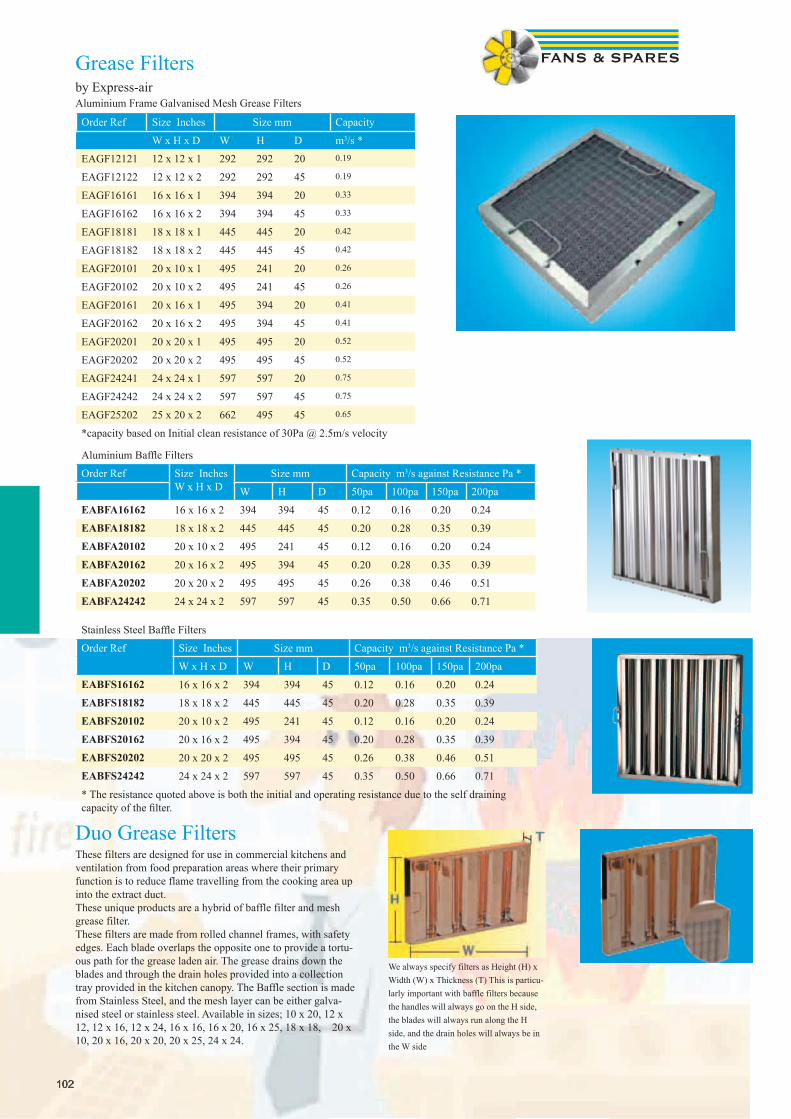
102102
Grease Filtersby Express-airAluminium Frame Galvanised Mesh Grease Filters
Order Ref Size Inches Size mm Capacity
W x H x D W H D m3/s *
EAGF12121 12 x 12 x 1 292 292 20 0.19
EAGF12122 12 x 12 x 2 292 292 45 0.19
EAGF16161 16 x 16 x 1 394 394 20 0.33
EAGF16162 16 x 16 x 2 394 394 45 0.33
EAGF18181 18 x 18 x 1 445 445 20 0.42
EAGF18182 18 x 18 x 2 445 445 45 0.42
EAGF20101 20 x 10 x 1 495 241 20 0.26
EAGF20102 20 x 10 x 2 495 241 45 0.26
EAGF20161 20 x 16 x 1 495 394 20 0.41
EAGF20162 20 x 16 x 2 495 394 45 0.41
EAGF20201 20 x 20 x 1 495 495 20 0.52
EAGF20202 20 x 20 x 2 495 495 45 0.52
EAGF24241 24 x 24 x 1 597 597 20 0.75
EAGF24242 24 x 24 x 2 597 597 45 0.75
EAGF25202 25 x 20 x 2 662 495 45 0.65
*capacity based on Initial clean resistance of 30Pa @ 2.5m/s velocity
Aluminium Baffl e Filters
Order Ref Size InchesW x H x D
Size mm Capacity m3/s against Resistance Pa *
W H D 50pa 100pa 150pa 200paEABFA16162 16 x 16 x 2 394 394 45 0.12 0.16 0.20 0.24EABFA18182 18 x 18 x 2 445 445 45 0.20 0.28 0.35 0.39EABFA20102 20 x 10 x 2 495 241 45 0.12 0.16 0.20 0.24EABFA20162 20 x 16 x 2 495 394 45 0.20 0.28 0.35 0.39EABFA20202 20 x 20 x 2 495 495 45 0.26 0.38 0.46 0.51EABFA24242 24 x 24 x 2 597 597 45 0.35 0.50 0.66 0.71
Stainless Steel Baffl e Filters
Order Ref Size Inches Size mm Capacity m3/s against Resistance Pa *
W x H x D W H D 50pa 100pa 150pa 200paEABFS16162 16 x 16 x 2 394 394 45 0.12 0.16 0.20 0.24EABFS18182 18 x 18 x 2 445 445 45 0.20 0.28 0.35 0.39EABFS20102 20 x 10 x 2 495 241 45 0.12 0.16 0.20 0.24EABFS20162 20 x 16 x 2 495 394 45 0.20 0.28 0.35 0.39EABFS20202 20 x 20 x 2 495 495 45 0.26 0.38 0.46 0.51EABFS24242 24 x 24 x 2 597 597 45 0.35 0.50 0.66 0.71
* The resistance quoted above is both the initial and operating resistance due to the self draining capacity of the fi lter.
Duo Grease Filters These filters are designed for use in commercial kitchens and ventilation from food preparation areas where their primary function is to reduce flame travelling from the cooking area up into the extract duct. These unique products are a hybrid of baffle filter and mesh grease filter.These filters are made from rolled channel frames, with safety edges. Each blade overlaps the opposite one to provide a tortu-ous path for the grease laden air. The grease drains down the blades and through the drain holes provided into a collection tray provided in the kitchen canopy. The Baffle section is made from Stainless Steel, and the mesh layer can be either galva-nised steel or stainless steel. Available in sizes; 10 x 20, 12 x 12, 12 x 16, 12 x 24, 16 x 16, 16 x 20, 16 x 25, 18 x 18, 20 x 10, 20 x 16, 20 x 20, 20 x 25, 24 x 24.
We always specify filters as Height (H) x Width (W) x Thickness (T) This is particu-larly important with baffle filters becausethe handles will always go on the H side, the blades will always run along the H side, and the drain holes will always be in the W side
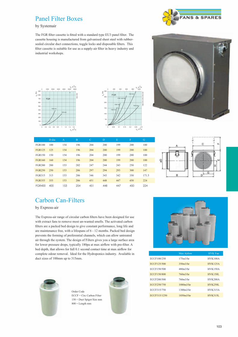
103
Panel Filter Boxesby Systemair
The FGR fi lter cassette is fi tted with a standard type EU3 panel fi lter. The cassette housing is manufactured from galvanised sheet steel with rubber- sealed circular duct connections, toggle locks and disposable fi lters. This fi lter cassette is suitable for use as a supply-air fi lter in heavy industry and industrial workshops.
D dia A B C D E F G
FGR100 100 154 196 204 200 199 200 100
FGR125 125 154 196 204 200 199 200 100
FGR150 150 154 196 204 200 199 200 100
FGR160 160 154 196 204 200 199 200 100
FGR200 200 153 202 247 244 243 250 122
FGR250 250 153 206 297 294 293 300 147
FGR315 315 153 206 346 343 342 350 171.5
FGR355 355 153 206 451 448 447 450 224
FGR400 400 153 254 451 448 447 450 224
Carbon Can-Filtersby Express-air
The Express-air range of circular carbon fi lters have been designed for use with extract fans to remove most un-wanted smells. The activated carbon fi lters are a packed bed design to give constant performance, long life and are maintenance free, with a lifespans of 6 - 12 months. Packed bed design prevents the forming of preferential channels, which can allow untreated air through the system. The design of Filters gives you a large surface area for lower pressure drops, typically 180pa at max airfl ow with pre-fi lter. A bed depth, that allows for full 0.1 second contact time at max airfl ow for complete odour removal. Ideal for the Hydroponics industry. Available in duct sizes of 100mm up to 315mm.
�
Max Airlow HVK Fan
ECCF100/250 175m3/hr HVK100A
ECCF125/500 350m3/hr HVK125A
ECCF150/500 480m3/hr HVK150A
ECCF150/800 760m3/hr HVK150L
ECCF200/500 760m3/hr HVK200A
ECCF250/750 1080m3/hr HVK250L
ECCF315/750 1300m3/hr HVK315A
ECCF315/1250 1850m3/hr HVK315L
Order CodeECCF = Circ Carbon Filter150 = Duct Spigot Size mm800 = Length mm

104
Heating & Cooling ProductsCooling PrCooling Pr

105105
With 75 years of experience behind us we create the energy efficient solutions for comfortable indoor climates of today. Our products are ef-ficient, energy saving and have an attractive design which means that they blend in to different types of sites.
Air curtains; Separating different climate zones by an invisible curtain of air gives large energy savings and a comfortable indoor climate. Our three different brands gives us a complete product selection: Frico stands for the energy efficient and well designed standard solutions, Gelu creates tailormade products and Shearflow gives us powerful solutions at an attractive price. Radiant heaters; Radiant heaters heat people, not the surrounding air. The radiated heat “naturally” migrates to where it is most needed, which facilitates the creation of a comfortable indoor climate. Fan heaters; Fan heaters provide effective heating at a low cost. Our fan heaters are robust and reliable, have low noise levels andextremely long service lives.Ceiling fans; Ceiling fans force over-heated air from the ceiling down to the occupation zone and in this way save energy and increase the heatcomfort. The savings in premises with high ceilings are very large. Convectors; Convectors provide good heat distribution and the warm air flow directed upwards can be used to counter-act cold drafts from the windows. Regulators; The regulation system is the brain of a heating system and is decisive for comfort level and energy consumption. Frico offer a wide range of regulators to give the selection options depending on how advanced a solution one is looking for and what environment it is to be used in.
With 75 years of experience behind us we create the energy efficient solutions for comfortable indoor climates of today. Our products are ef-ficient, energy saving and have an attractive design which means that they blend in to different types of sites.
Air curtains; Separating different climate zones by an invisible curtain of air gives large energy savings and a comfortable indoor climate. Our three different brands gives us a complete product selection: Frico stands for the energy efficient and well designed standard solutions, Gelu creates tailormade products and Shearflow gives us powerful solutions at an attractive price. Radiant heaters; Radiant heaters heat people, not the surrounding air. The radiated heat “naturally” migrates to where it is most needed, which facilitates the creation of a comfortable indoor climate. Fan heaters; Fan heaters provide effective heating at a low cost. Our fan heaters are robust and reliable, have low noise levels andextremely long service lives.Ceiling fans; Ceiling fans force over-heated air from the ceiling down to the occupation zone and in this way save energy and increase the heatcomfort. The savings in premises with high ceilings are very large. Convectors; Convectors provide good heat distribution and the warm air flow directed upwards can be used to counter-act cold drafts from the windows. Regulators; The regulation system is the brain of a heating system and is decisive for comfort level and energy consumption. Frico offer a wide range of regulators to give the selection options depending on how advanced a solution one is looking for and what environme
Thermozone TechnologyThirty years of air curtain development in the demanding Scandinavian climate has given us a unique platform to create air curtains with optimal door protection.Thermozone air curtains are optimized in:Airflow geometry Performance Sound levelFrico co-operate with leading architects and product designers to create today’s aesthetic products.Frico offers a wide range of options with or without heat and for all openings from service hatches to aircraft hangers.
Thermozone SF is an ideal solution for any environment with revolving doors. The air cur-tain is mounted vertically and its curved design integrates neatly with the door. Thermozone SF efficiently protects the exposed area just above
Portier is an exclusive air curtain in brushed stainless steel. Installed above entrance doors and smaller doors of up to 2.5 meters in height.
AR300 is especially suited for environments with high demands in respect of design. The recessed installation is very discrete and the built-in control contributes further to the concealed appearance.
The Thermozone AC/WAC 300/400 range consists of both heated and ambient versions and hot water heated WAC models.AC/WAC300/400 are designed for perma-nent horizontal installation above doorways with heights between 2,5 and 4,0 metres or positioned vertically beside the doorway when overdoor space is limited. They can be surface mounted or recessed into a false
* Designed for floor-standing mounting in larger entrances and doors. * Clean, stylish and simple design ideal for both shop entrances and industrial doors.* An adjustable air oulet grille makes it pos-sible to direct the air for an optimal air curtain effect.
AGI is a robust air curtain for industrial doors that can be mounted horizontally or vertically. It is avail-able in four module lengths which can easily be com-bined to cover the individual needs of every door.The air flow is regulated using a 5-step transformer or continuously variable 3-phase control.
The Thermozone PA1000 Range comprises of 4 door heaters. The range starts with the PA1006E03, a 3kW, 650mm long single phase door heater. The range extends further with the PA1008 which is available in 3 versions depending upon the heat output required. The PA1008 has three models all 860mm in length supplying 2kW, 3kW and 5kW of heat respectively. The com-plete PA1008 range is single phase. BUDGET PRICED!
Air Curtains

106
Radiant heatingEfficient heatingThe heat from radiant heaters is emitted as soon as the rays hit a surface and there are no losses on the way. The heat is then transmitted to the air which means that the temperature can be lowered with a maintained comfort level. Radiant heaters also give instant heat.Zone and spot heatingWith radiant heating systems, different zones within the same room can have different temperatures. This means energy can be saved and comfort increased. Radiant heaters also provide efficient and economical protection against cold draughts. The radiated heat “naturally” migrates to where it is most needed, which means that cold surfaces such as windows will attract the radiant heating. Discrete heatingRadiant heaters heat without being seen or heard. They have a discrete design that blend in well in all environments and the heating cause no air movements.
Radiant heater for ceiling heights between 4 and 15 metres.
efficient and economical protection against cold draughts. The
metres.
IR is suitable for total or supplementary heating of premises with large volume and high ceilings. It can also be used outdoors for example on sports arena stands or to keep loading bays dry and frostless.
Water heated radiant heater for recessed mounting in false ceilings.
Fan heaters (Electric & LPHW)Tiger is a range of fan heaters for portable use. The compact and robust design makes them suitable for use in workshops, garages and retail areas. Tiger can easily be wall mounted.The built-in thermostat regulates fan speed and heat, or just the heat.
Fan heater SW is designed for heating of industrial premises, work shops, storage rooms, supermarkets, etc. Modern fan technology optimises the air flow through the heater battery, achieving sound levels as low as 35 dB(A). The balanced motor and axial fan combination supplies a smooth flow of heat from the water coil. Provided with air directors. The fan heater can be wall or ceiling mounted with water connec-tion on either side. Regulation of air flow in three stagesRegulators / Controls
The control system is the “heart” and the “brain” of a heating system and often decisive for both comfort level and energy consumption. The temperature of an electric heating system can be quickly, easily, and exactly regulated more than in any other heating system.
The heat balance in a building is a dynamic interplay of several factors that can be divided into three main groups:* Heat losses* Heat contribution* Heat storageThe purpose of heating (the heat contribution) is to cover the differences between the various posts so that the desired temperature can be maintained in the building. In practice, both the climatic stresses (outside temperature, sunshine, wind) and the heat contribution to a building vary over time. The vari-ations can be long-term, such as with the seasons, or shorter, such as when the sun is hidden by clouds, a room is filled with people, or when a door is opened. The ability of the sections of the building to store heat is of great significance for the shorter variations. One of the greatest advantages of an electric heating system is that temperature can be regulated simply, quickly, and more exact than in any other heating system. It is however vital to choose the right control and regulation system, as it determines the comfort level and energy consumption of the building.
The air curtain control box CK02EC/CK02WC, level 2, makes it easier to install air curtains.All accessories are collected in a practical box
ADEA is an advanced and user friendly regulator for air curtains. ADEA is ready to run directly after installation on account of the pre-programmed parameters. An outdoor sensor, room sensor and door contact govern the regulator, which adapts the heat and fan speed, according to the preset parameters, to the prevailing conditions.
CIRT is a variable output regulator with a timer, primarily intended for infrared heaters and other radiant heaters.The built-in timer can be set for 0,5 to 4 or 4 to 24 hours. IP44.
Exceptionally silentOne of the most important moments in our product develop-ment, is the construction of silent fan heaters. At our plant in Skinnskatteberg, Sweden, you will find one of the most sophisticated air and sound laboratories in Europe.Lots of power, small investmentCompared to other heating systems, the investment cost for a fan heater is low. Frico fan heaters give you lots of power for the money.Compact and robustFrico fan heaters are compact and light. Therefore they are easy to carry around or can easily be mounted on the wall. The heaters are also very robust and withstand heavy handling in aggressive environments.Heating and ventilationA great advantage of a fan heater is the option of combining heating and ventilation. Mixing cabinets for a stationary fan heaters create economic heating and ventilation, by mixing the return air with fresh air.
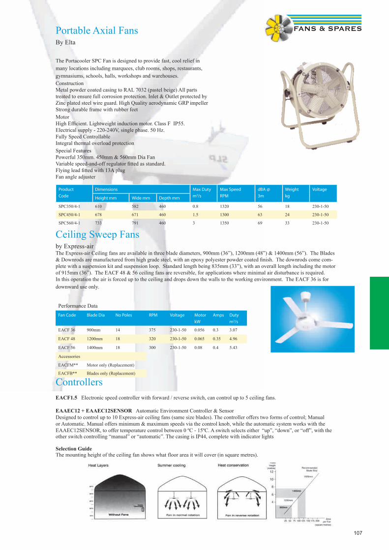
107
Ceiling Sweep Fansby Express-airThe Express-air Ceiling fans are available in three blade diameters, 900mm (36”), 1200mm (48”) & 1400mm (56”). The Blades & Downrods are manufactured from high grade steel, with an epoxy polyester powder coated fi nish. The downrods come com-plete with a suspension kit and suspension loop. Standard length being 835mm (33”), with an overall length including the motor of 915mm (36”). The EACF 48 & 56 ceiling fans are reversible, for applications where minimal air disturbance is required. In this operation the air is forced up to the ceiling and drops down the walls to the working environment. The EACF 36 is for downward use only.
Performance Data
Fan Code Blade Dia No Poles RPM Voltage Motor
kW
Amps Duty
m3/s
EACF 36 900mm 14 375 230-1-50 0.056 0.3 3.07
EACF 48 1200mm 18 320 230-1-50 0.065 0.35 4.96
EACF 56 1400mm 18 300 230-1-50 0.08 0.4 5.43
Accessories
EACFM** Motor only (Replacement)
EACFB** Blades only (Replacement)
ControllersEACF1.5 Electronic speed controller with forward / reverse switch, can control up to 5 ceiling fans.
EAAEC12 + EAAEC12SENSOR Automatic Environment Controller & SensorDesigned to control up to 10 Express-air ceiling fans (same size blades). The controller offers two forms of control; Manual or Automatic. Manual offers minimum & maximum speeds via the control knob, while the automatic system works with the EAAEC12SENSOR, to offer temperature control between 0 ºC - 15ºC. A switch selects either “up”, “down”, or “off”, with the other switch controlling “manual” or “automatic”. The casing is IP44, complete with indicator lights
Selection GuideThe mounting height of the ceiling fan shows what floor area it will cover (in square metres).
Portable Axial FansBy Elta
The Portacooler SPC Fan is designed to provide fast, cool relief in many locations including marquees, club rooms, shops, restaurants, gymnasiums, schools, halls, workshops and warehouses.ConstructionMetal powder coated casing to RAL 7032 (pastel beige) All parts treated to ensure full corrosion protection. Inlet & Outlet protected by Zinc plated steel wire guard. High Quality aerodynamic GRP impellerStrong durable frame with rubber feetMotorHigh Effi cient. Lightweight induction motor. Class F IP55. Electrical supply - 220-240V, single phase. 50 Hz.Fully Speed ControllableIntegral thermal overload protectionSpecial FeaturesPowerful 350mm. 450mm & 560mm Dia FanVariable speed-and-off regulator fi tted as standard.Flying lead fi tted with 13A plugFan angle adjuster
Product
Code
Dimensions Max Duty
m3/s
Max Speed
RPM
dBA @
3m
Weight
kg
Voltage
Height mm Wide mm Depth mm
SPC350/4-1 610 582 460 0.8 1320 56 18 230-1-50
SPC450/4-1 678 671 460 1.5 1300 63 24 230-1-50
SPC560/4-1 733 791 460 3 1350 69 33 230-1-50
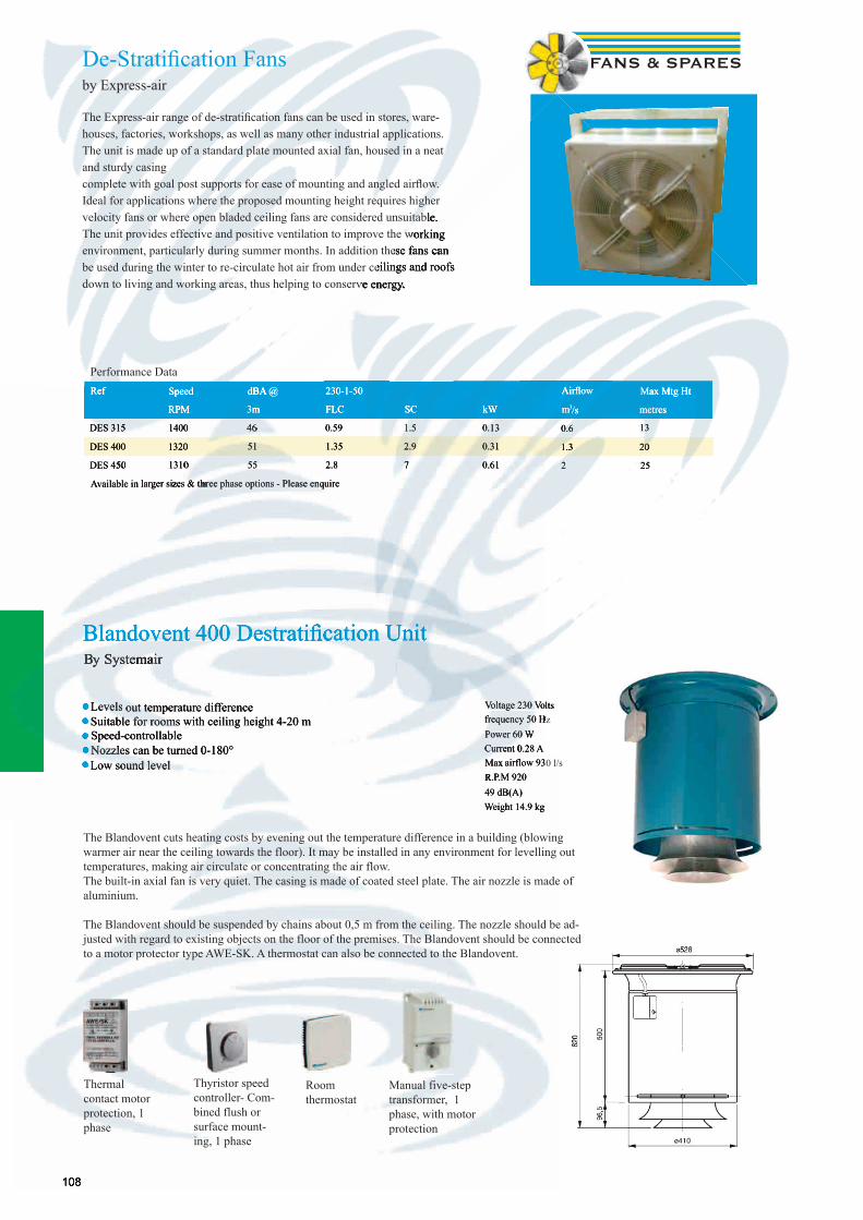
108108
• Levels out temperature difference• Suitable for rooms with ceiling height 4-20 m• Speed-controllable• Nozzles can be turned 0-180°• Low sound level
The Blandovent cuts heating costs by evening out the temperature difference in a building (blowing warmer air near the ceiling towards the floor). It may be installed in any environment for levelling out temperatures, making air circulate or concentrating the air flow. The built-in axial fan is very quiet. The casing is made of coated steel plate. The air nozzle is made of aluminium.
The Blandovent should be suspended by chains about 0,5 m from the ceiling. The nozzle should be ad-justed with regard to existing objects on the floor of the premises. The Blandovent should be connected to a motor protector type AWE-SK. A thermostat can also be connected to the Blandovent.
Blandovent 400 Destratifi cation UnitBy Systemair
Thermal contact motor protection, 1 phase
Thyristor speed controller- Com-bined flush or surface mount-ing, 1 phase
Room thermostat
Manual five-step transformer, 1 phase, with motor protection
Voltage 230 Voltsfrequency 50 HzPower 60 WCurrent 0.28 AMax airflow 930 l/sR.P.M 92049 dB(A)Weight 14.9 kg
De-Stratifi cation Fansby Express-air
The Express-air range of de-stratifi cation fans can be used in stores, ware-houses, factories, workshops, as well as many other industrial applications. The unit is made up of a standard plate mounted axial fan, housed in a neat and sturdy casing complete with goal post supports for ease of mounting and angled airfl ow. Ideal for applications where the proposed mounting height requires higher velocity fans or where open bladed ceiling fans are considered unsuitable. The unit provides effective and positive ventilation to improve the working environment, particularly during summer months. In addition these fans can be used during the winter to re-circulate hot air from under ceilings and roofs down to living and working areas, thus helping to conserve energy.
Performance DataRef Speed dBA @ 230-1-50 Airfl ow Max Mtg Ht
RPM 3m FLC SC kW m3/s metres
DES 315 1400 46 0.59 1.5 0.13 0.6 13
DES 400 1320 51 1.35 2.9 0.31 1.3 20
DES 450 1310 55 2.8 7 0.61 2 25
Available in larger sizes & three phase options - Please enquire
Voltage 230 Voltsfrequency 50 Hz
velocity fans or where open bladed ceiling fans are considered unsuitable. The unit provides effective and positive ventilation to improve the working environment, particularly during summer months. In addition these fans can environment, particularly during summer months. In addition these fans can be used during the winter to re-circulate hot air from under ceilings and roofs be used during the winter to re-circulate hot air from under ceilings and roofs down to living and working areas, thus helping to conserve energy.down to living and working areas, thus helping to conserve energy.
Airfl ow Max Mtg Ht
m3/s metres
0.6 13
1.3 20
2 25
•• Levels out temperature difference•• Suitable for rooms with ceiling height 4-20 m Suitable for rooms with ceiling height 4-20 m•• Speed-controllable Speed-controllable•• Nozzles can be turned 0-180°Nozzles can be turned 0-180°•• Low sound level Low sound level
Blandovent 400 Destratifi cation UnitBy Systemair
frequency 50 HzPower 60 WCurrent 0.28 AMax airflow 930 l/sR.P.M 92049 dB(A)Weight 14.9 kg
Ref Speed dBA @
RPM
DES 315 1400
DES 400 1320
DES 450DES 450 1310
Available in larger sizes & three phase options - Please enquireAvailable in larger sizes & three phase options - Please enquire
Blandovent 400 Destratifi cation Unit
Voltage 230 Voltsfrequency 50 HzPower 60 WCurrent 0.28 AMax airflow 930 l/sR.P.M 920
dBA @ 230-1-50
3m FLC SC kW
4646 0.59 1.5 0.13
51 1.35 2.9 0.31
1310 55 2.8 7 0.61
Available in larger sizes & three phase options - Please enquireAvailable in larger sizes & three phase options - Please enquire
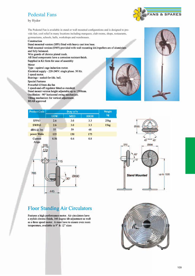
109
Pedestal Fansby Hydor
The Pedestal Fan is available in stand or wall mounted confi gurations and is designed to pro-vide fast, cool relief in many locations including marquees, club rooms, shops, restaurants, gymnasiums, schools, halls, workshops and warehouses.ConstructionStand mounted version (SPF) fi tted with heavy cast iron base.Wall mounted version (SWF) provided with wall mounting kit.Impellers are of aluminium and fully balanced.Wire guards of chrome plated mesh.All Steel components have a corrosion resistant fi nish.Supplied in Kit form for ease of assemblyMotorType - squirrel cage induction motor.Electrical supply - 220-240V. single phase. 50 Hz.3 speed motor.Bearings - sealed-for-life. ball.Special FeaturesPowerful 635mm dia fan3 speed-and-off regulator fi tted as standard.Stand mount version height adjustable up to 1500mm.Oscillation - 90° horizontal swing mechanism.Tilting mechanism for vertical adjustment.BEAB approved
Product Code Duty m3/s Weight kgLOW MED HIGH
SPF63 2.6 3.0 3.3 25kg
SWF63 2.6 3.0 3.3 15kg
dBA @ 3m 55 59 68
power Watts 135 150 175
Current Amps
0.56 0.6 0.8
Floor Standing Air CirculatorsFeatures a high performance motor. Air circulators have a stylish chrome finish, 360 degree tilt adjustment as well as a three speed motor. A must have to ensure even room temperature, available in 9” & 12” sizes
ConstructionStand mounted version (SPF) fi tted with heavy cast iron base.Wall mounted version (SWF) provided with wall mounting kit.Impellers are of aluminium and fully balanced.Wire guards of chrome plated mesh.All Steel components have a corrosion resistant fi nish.Supplied in Kit form for ease of assemblyMotorType - squirrel cage induction motor.Electrical supply - 220-240V. single phase. 50 Hz.3 speed motor.Bearings - sealed-for-life. ball.Special FeaturesPowerful 635mm dia fan3 speed-and-off regulator fi tted as standard.Stand mount version height adjustable up to 1500mm.Oscillation - 90° horizontal swing mechanism.Tilting mechanism for vertical adjustment.BEAB approved
Product Code Duty m3/s Weight kgLOW MED HIGH
SPF63 2.6 3.0 3.3 25kg
SWF63 2.6 3.0 3.3 15kg
dBA @ 3m 55 59 68
power Watts 135 150 175
Current Amps
0.56 0.6 0.8
Floor Standing Air CirculatorsFeatures a high performance motor. Air circulators have a stylish chrome finish, 360 degree tilt adjustment as well as a three speed motor. A must have to ensure even room temperature, available in 9” & 12” sizes

110110
Portable Air Conditioning Unitsby VorticePolar M10 EA
A B C Kg Duct dia
410 753 392 29 120mm
Product Code Power
Btu/h
Operating
temperature
kW V A M3/h Recommended
room size
Cooling
W
Compressor
Polar M10 EA 65098 8150 18ºC - 32ºC .834 230 2.5 350 60m3 2390 Rotary
• New generation all in one air conditioner with all the advantages of the electronic Polar range. High quality construction, easy to use and to install.The new design together with the use of R410A cooling gas makes this one of the leaders in it’s category for performance and effi cient use of energy and environmental respect.Performance EER and yearly consumption (according to EN14511) are TUV certifi ed.The automatic water drainage system collects the dampness from the environment, evaporates it and fi nally expels the vapour through the hot air extraction duct.
Standard accessoriesWashable anti-dustfi lter which traps the impurities present in the air drawn through the unit, preventing their circulation in the air-conditioned room.Activated carbon fi lter.Three washable anti-dust fi lters to protect the heat exchanger of the condensing unit.The supplied remote control can be used up to 10 metres from the unit.An exhaust vent for expelling warm air through window or door is included.A two speed function and timer are included.
Self Contained Wall Mounted Air Conditioning Units by Xpelair
Digitemp series; WA210, WA245, WHP210, WHP245
Digitemp, from low carbon ventilation specialist Xpelair, gives summer cooling and winter warmth from its stylish wall mounted units. Quickly and simply installed from inside the room, even at multiple stories, to a patented external folding grille system. This eliminates the need for awkward and sometimes impossible external access.Xpelair’s Digitemp comfort cooling technology is designed specifically for domestic and spe-cific small commercial use, to give year round economical heating and cooling comfort; as an advanced ‘air to air’ heat-pump Digitemp is part of Xpelair’s carbon saving CarbonLite range. Despite this impressive low carbon performance, the whole thing fits into a modern, stylish case. With no outdoor condensing unit to install and no gas connection necessary, the unit can be fitted at high or low level for optimum flexibility without specialist skills. The integral refrigerant system is factory sealed, so installation does not require the opening of the entire system or any connection to hoses. Cooling, heating and dehumidification are regulated by the convenient hand-held remote con-trol and all operational modes are programmable using the infrared handset – allowing total control and adjustment from distance.Digitemp uses a three-speed fan including night mode for extra quiet operation. Economic and efficient, Digitemp combines low carbon, low power consumption when cooling, with a high efficiency heating capacity. Two of the models, the WA210N and WA245N provide cooling only, whilst the WHP210N and WHP245N deliver the convenience of heating and cooling in one advanced unit.
Wall Mounted Air Conditioning Units
Compressor
Rotary

111
Wall Mounted Air Conditioning Unitsby Airwell
Performance, aesthetics and comfort are all advantages that characterise the FLORIDA N wall-mounted unit range. With its refi ned design, tried and tested technology and reliable components, the Florida wall-mounted range can also offer unrivalled heat comfort and air quality, which means that it can be incorporated into all residential and commercial buildings. With extremely low noise levels, a broad operating range, the eco-friendly fl uid R410A and energy label A (depending on model), the FLORIDA A wall-mounted unit range has been designed to provide a very high comfort level and to be very easy to fi t for install-ers.
• Cooling Only Models 2.23kW – 8.8kW• Heat Pump Models 2.28kW – 9.09kW• Infrared remote control
• Night-Time slow running• Three levels of fi ltration• Energy Effi cient
FLO N Cooling Only FLO 7 N FLO 9 N FLO 12 N FLO 14 N FLO 18 N FLO 24 N FLO 30 N
FLO N Heat Pump FLO 7 N RC FLO 9 N RC FLO 12 N RC FLO 14 N RC FLO 18 N RC FLO 24 N RC FLO 30 N RC
Heating Capacity (1) kW 2.28 3 4 4.48 5.56 7.37 9.09
Power input kW 0.66 0.85 1.14 1.39 1.6 2.4 3.06
COP / Energy Label 3.45 / B 3.52 / B 3.51 / B 3.22 / C 3.46 / B 3.07 / D 2.97 / D
Cooling Capacity (2) kW 2.23 2.72 3.63 4 5.5 6.81 8.8
Power input kW 0.68 0.82 1.1 1.33 1.69 2.26 3.01
EER / Energy Label 3.23 / A 3.31 / A 3.3 / A 3.03 / B 3.22 / A 3.01 / B 2.92 / C
INDOOR UNITS
Dehumidifi cation l/h 0.7 0.9 1.3 1.5 1.8 2.66 3.2
Airfl ow (LS/NS/HS) m3/hr 280/320/380 330/380/450 450/550/635 475/550/660 750/840/930 840/930/990 830/1040/1250
Acoustic pressure to 1m (LS/NS/HS) (3)
dB(A) 25/27/30 28/31/35 35/39/43 36/41/46 37/40/43 40/42/45 47/51/55
Net Weight kg 11 11 11.5 11.5 14 15 17
Dimensions (WxDxH) mm 810x190x285 810x190x285 810x190x285 810x190x285 1060x210x295 1060x210x295 1200x236x340
GC 7 N GC 9 N GC 12 N GC 14 N GC 18 N GC 24 N GC 30 N
OUTDOOR UNITS GC 7 NRC GC 9 NRC GC 12 NRC GC 14 NRC GC 18 NRC GC 24 NRC GC 30 NRC
Compressor Type Rotary Rotary Rotary Rotary Rotary Rotary Scroll
Operating Limits Winter/Summer (4)
-10 ºC / + 43 C76
Airfl ow m3/hr 1660 1780 1850 2160 2480 2480 3110
Acoustic pressure to 1m dB(A) 47 49 53 54 57 58 60
Weight kg 32 35 35 38 56 56 82
Dimensions (WxDxH) 795x290x610 795x290x610 795x290x610 795x290x610 846x302x690 846x302x690 900x340x970
LINKING SPECIFICATION BETWEEN INDOOR AND OUTDOOR UNITS
1-230V Power Supply
Power Supply Side Indoor Indoor Indoor Indoor Ind. or Out. Ind. or Out. Outdoor
Power cable section mm² 3x1.5 3x1.5 3x1.5 3x1.5 3x1.5 3x2.5 3x2.5
Fuse amp A 10 10 15 15 15 20 32
Electrical connection Ind./Out.
mm² 5x1.5 5x1.5 5x1.5 5x1.5 6x1.5 6x1.5 6x1.5
3N-400V Power Supply
Power Supply Side - - - - Outdoor Outdoor Outdoor
Power cable section mm² - - - - 5x1.5 5x1.5 5x1.5
Fuse amp A - - - - - 6 6
Electrical connection Ind./Out.
mm² - - - - 6x1.5 6x1.5 6x1.5
LINKING PIPES
Max. Length m 15 15 15 15 25 25 25
Max. Height m 7 7 7 7 15 15 15
Suction pipe Diameter inches 3/8” 3/8” 3/8” 1/2” 1/2” 3/8” 3/8”
Liquid pipe Diameter inches 1/4” 1/4” 1/4” 1/4” 1/4” 5/8” 5/8”
(1) Nominal heating capacity: international conditions 20ºC/12ºC damp - External air: 7ºC/6ºC damp. (2) Nominal cooling capacity: international conditions (Standards NF EN 255.2 / 814.2) - 27ºC/19ºC damp - External air: 35ºC/24ºC damp. (3) Overall acoustic pressure in dB(A) (1m) under nominal conditions: outdoor unit in a free fi eld over arefl ecting plane - indoor unit: installed in an average sized room. (4) Operating limit with all-seasons kit.
Wall Mounted Air Conditioning Unitsby Airwell
Performance, aesthetics and comfort are all advantages that characterise the FLORIDA N wall-mounted unit range. With its refi ned design, tried and tested technology and reliable components, the Florida wall-mounted range can also offer unrivalled heat comfort and air quality, which means that it can be incorporated into all residential and commercial buildings. With extremely low noise levels, a broad operating range, the eco-friendly fl uid R410A and energy label A (depending on model), the FLORIDA A wall-mounted unit range has been designed to provide a very high comfort level and to be very easy to fi t for install-ers.
• Cooling Only Models 2.23kW – 8.8kW• Heat Pump Models 2.28kW – 9.09kW• Infrared remote control
• Night-Time slow running• Three levels of fi ltration• Energy Effi cient
FLO N Cooling Only FLO 7 N FLO 9 N FLO 12 N FLO 14 N FLO 18 N FLO 24 N
FLO N Heat Pump FLO 7 N RC FLO 9 N RC FLO 12 N RC FLO 14 N RC FLO 18 N RC FLO 24 N RC
Heating Capacity (1) kW 2.28 3 4 4.48 5.56 7.37
Power input kW 0.66 0.85 1.14 1.39 1.6 2.4
COP / Energy Label 3.45 / B 3.52 / B 3.51 / B 3.22 / C 3.46 / B 3.07 / D
Cooling Capacity (2) kW 2.23 2.72 3.63 4 5.5 6.81
3.01
3.01 / B 2.92 / C
3.2
840/930/990 830/1040/1250
40/42/45 47/51/55
17
1060x210x295 1200x236x340
GC 24 N GC 30 N
OUTDOOR UNITS GC 7 NRC GC 9 NRC GC 12 NRC GC 14 NRC GC 18 NRC GC 24 NRC GC 30 NRC
Compressor Type Rotary Rotary Rotary Rotary Rotary Rotary Scroll
Operating Limits Winter/Summer (4)
-10 ºC / + 43 C76
Airfl ow m3/hr 1660 1780 1850 2160 2480 2480 3110
Acoustic pressure to 1m dB(A) 47 49 53 54 57 58 60
Weight kg 32 35 35 38 56 56 82
Dimensions (WxDxH) 795x290x610 795x290x610 795x290x610 795x290x610 846x302x690 846x302x690 900x340x970
LINKING SPECIFICATION BETWEEN INDOOR AND OUTDOOR UNITS
1-230V Power Supply
Power Supply Side Indoor Indoor Indoor Indoor Ind. or Out. Ind. or Out. Outdoor
Power cable section mm² 3x1.5 3x1.5 3x1.5 3x1.5 3x1.5 3x2.5 3x2.5
Fuse amp A 10 10 15 15 15 20 32
Electrical connection Ind./Out.
mm² 5x1.5 5x1.5 5x1.5 5x1.5 6x1.5 6x1.5 6x1.5
3N-400V Power Supply
Power Supply Side - - - - Outdoor Outdoor Outdoor
Power cable section mm² - - - - 5x1.5 5x1.5 5x1.5
Fuse amp A - - - - - 6 6
Electrical connection Ind./Out.
mm² - - - - 6x1.5 6x1.5 6x1.5
LINKING PIPES
Max. Length m 15 15 15 15 25 25 25
Max. Height m 7 7 7 7 15 15 15
Suction pipe Diameter inches 3/8” 3/8” 3/8” 1/2” 1/2” 3/8” 3/8”
Liquid pipe Diameter inches 1/4” 1/4” 1/4” 1/4” 1/4” 5/8” 5/8”
(1) Nominal heating capacity: international conditions 20ºC/12ºC damp - External air: 7ºC/6ºC damp. (2) Nominal cooling capacity: international conditions (Standards NF EN 255.2 / 814.2) - 27ºC/19ºC damp - External air: 35ºC/24ºC damp. (3) Overall acoustic pressure in dB(A) (1m) under nominal conditions: outdoor unit in a free fi eld over arefl ecting plane - indoor unit: installed in an average sized room. (4) Operating limit with all-seasons kit.conditions: outdoor unit in a free fi eld over arefl ecting plane - indoor unit: installed in an average sized room. (4) Operating limit with all-seasons kit.conditions: outdoor unit in a free fi eld over arefl ecting plane - indoor unit: installed in an average sized room. (4) Operating limit with all-seasons kit.conditions: outdoor unit in a free fi eld over arefl ecting plane - indoor unit: installed in an average sized room. (4) Operating limit with all-seasons kit.conditions: outdoor unit in a free fi eld over arefl ecting plane - indoor unit: installed in an average sized room. (4) Operating limit with all-seasons kit.conditions: outdoor unit in a free fi eld over arefl ecting plane - indoor unit: installed in an average sized room. (4) Operating limit with all-seasons kit.conditions: outdoor unit in a free fi eld over arefl ecting plane - indoor unit: installed in an average sized room. (4) Operating limit with all-seasons kit.conditions: outdoor unit in a free fi eld over arefl ecting plane - indoor unit: installed in an average sized room. (4) Operating limit with all-seasons kit.
Power input kW 0.68 0.82 1.1 1.33 1.69 2.26
EER / Energy Label 3.23 / A 3.31 / A 3.3 / A 3.03 / B 3.22 / A 3.01 / B
INDOOR UNITS
Dehumidifi cation l/h 0.7 0.9 1.3 1.5 1.8 2.66
Airfl ow (LS/NS/HS) m3/hr 280/320/380 330/380/450 450/550/635 475/550/660 750/840/930 840/930/990
Acoustic pressure to 1m (LS/NS/HS) (3)
dB(A) 25/27/30 28/31/35 35/39/43 36/41/46 37/40/43 40/42/45
Net Weight kg 11 11 11.5 11.5 14 15
Dimensions (WxDxH) mm 810x190x285 810x190x285 810x190x285 810x190x285 1060x210x295 1060x210x295
GC 7 N GC 9 N GC 12 N GC 14 N GC 18 N GC 24 N
OUTDOOR UNITS GC 7 NRC GC 9 NRC GC 12 NRC GC 14 NRC GC 18 NRC GC 24 NRC
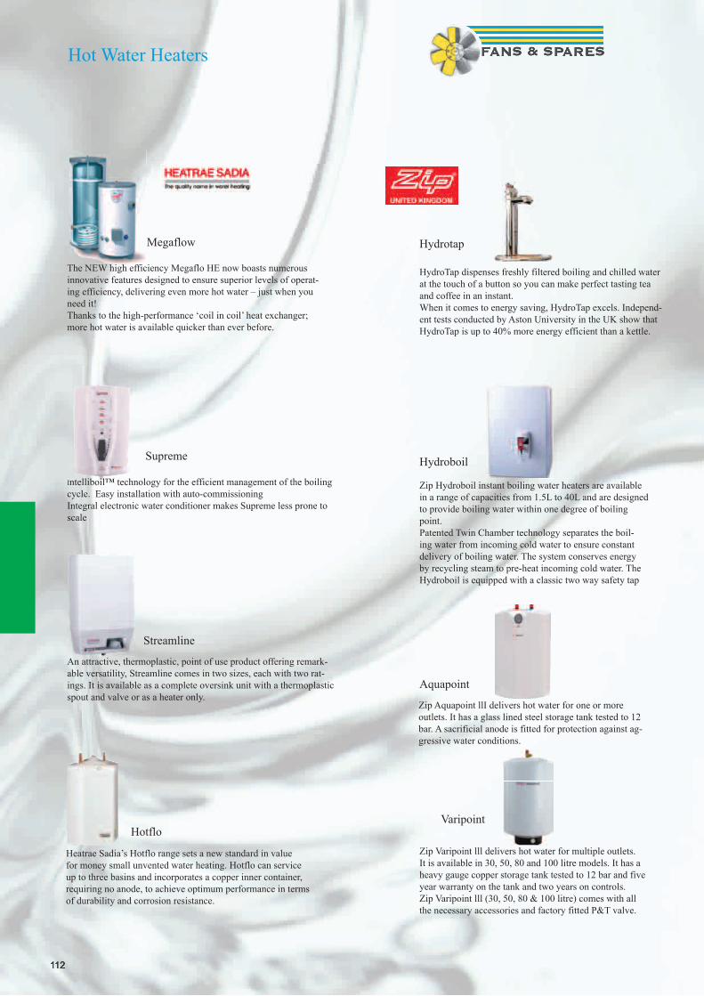
112112
The NEW high efficiency Megaflo HE now boasts numerous innovative features designed to ensure superior levels of operat-ing efficiency, delivering even more hot water – just when you need it!Thanks to the high-performance ‘coil in coil’ heat exchanger; more hot water is available quicker than ever before.
Intelliboil™ technology for the efficient management of the boiling cycle. Easy installation with auto-commissioning Integral electronic water conditioner makes Supreme less prone to scale
An attractive, thermoplastic, point of use product offering remark-able versatility, Streamline comes in two sizes, each with two rat-ings. It is available as a complete oversink unit with a thermoplastic spout and valve or as a heater only.
Megaflow
Supreme
Streamline
Heatrae Sadia’s Hotflo range sets a new standard in value for money small unvented water heating. Hotflo can service up to three basins and incorporates a copper inner container, requiring no anode, to achieve optimum performance in terms of durability and corrosion resistance.
Hotflo
HydroTap dispenses freshly filtered boiling and chilled water at the touch of a button so you can make perfect tasting tea and coffee in an instant. When it comes to energy saving, HydroTap excels. Independ-ent tests conducted by Aston University in the UK show that HydroTap is up to 40% more energy efficient than a kettle.
Hydrotap
Zip Hydroboil instant boiling water heaters are available in a range of capacities from 1.5L to 40L and are designed to provide boiling water within one degree of boiling point. Patented Twin Chamber technology separates the boil-ing water from incoming cold water to ensure constant delivery of boiling water. The system conserves energy by recycling steam to pre-heat incoming cold water. The Hydroboil is equipped with a classic two way safety tap
Hydroboil
Zip Aquapoint llI delivers hot water for one or more outlets. It has a glass lined steel storage tank tested to 12 bar. A sacrificial anode is fitted for protection against ag-gressive water conditions.
Aquapoint
Zip Varipoint lll delivers hot water for multiple outlets. It is available in 30, 50, 80 and 100 litre models. It has a heavy gauge copper storage tank tested to 12 bar and five year warranty on the tank and two years on controls.Zip Varipoint lll (30, 50, 80 & 100 litre) comes with all the necessary accessories and factory fitted P&T valve.
Varipoint
Hot Water Heaters

113
Volume Control, Smoke & Fire DampersDampers
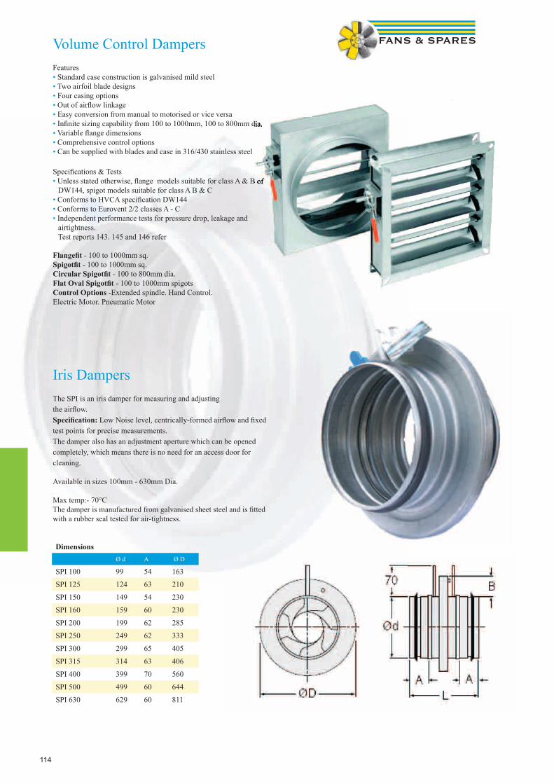
114
Volume Control DampersFeatures • Standard case construction is galvanised mild steel• Two airfoil blade designs• Four casing options• Out of airfl ow linkage• Easy conversion from manual to motorised or vice versa• Infi nite sizing capability from 100 to 1000mm, 100 to 800mm dia.• Variable fl ange dimensions• Comprehensive control options• Can be supplied with blades and case in 316/430 stainless steel
Specifi cations & Tests• Unless stated otherwise, fl ange models suitable for class A & B of DW144, spigot models suitable for class A B & C• Conforms to HVCA specifi cation DW144• Conforms to Eurovent 2/2 classes A - C• Independent performance tests for pressure drop, leakage and airtightness. Test reports 143. 145 and 146 refer
Flangefi t - 100 to 1000mm sq.Spigotfi t - 100 to 1000mm sq.Circular Spigotfi t - 100 to 800mm dia.Flat Oval Spigotfi t - 100 to 1000mm spigotsControl Options -Extended spindle. Hand Control. Electric Motor. Pneumatic Motor
Iris Dampers The SPI is an iris damper for measuring and adjusting the airfl ow. Specifi cation: Low Noise level, centrically-formed airfl ow and fi xed test points for precise measurements. The damper also has an adjustment aperture which can be opened completely, which means there is no need for an access door for cleaning. Available in sizes 100mm - 630mm Dia.
Max temp:- 70°C The damper is manufactured from galvanised sheet steel and is fi tted with a rubber seal tested for air-tightness.
DimensionsØ d A Ø D
SPI 100 99 54 163
SPI 125 124 63 210
SPI 150 149 54 230
SPI 160 159 60 230
SPI 200 199 62 285
SPI 250 249 62 333
SPI 300 299 65 405
SPI 315 314 63 406
SPI 400 399 70 560
SPI 500 499 60 644
SPI 630 629 60 811
Infi nite sizing capability from 100 to 1000mm, 100 to 800mm dia.
Unless stated otherwise, fl ange models suitable for class A & B of

115115
Smoke dampersFeatures• Standard blade and case construction is galvanised mild steel, with grade 302S stainless steel side seals• Unique one piece double-skin interlocking airfoil blades• Four casing options• Linkage out of airfl ow• Optional blades and case in grades 316 or 430 stainless steel• Grade 316 stainless steel side seals available to order• Infi nite sizing capability from 100sq.mm, to 1200sq.mm• Variable fl ange dimensions and casing widths
Specifi cations & Tests• Unless stated otherwise, fl ange models suitable for class A & B of DW144, spigot models suit-able for class A B & C• Conforms to HVCA specifi cation DW144• Conforms to Eurovent 2/2 classes A - C• Blade construction fi re tested to BS476 part20; 1987 for integrity and leakage• Elevated temperature tests, reports 231297, 234486 and 127438 refer• Resistance tested by BSRIA, report 15633/1 refers• Leakage tested by BSRIA, report 15633/1 refers• 28 day salt corrosion tested Chatfi eld report RLR3 refers
Electric Actuators
Air Control Dampers
Model Torque Operations
Nm
NM 24 A 10 Open/Close
NM 230 A 10 Open/Close
NM 24A - SR 10 Open/Close
SM 24 A 20 Open/Close
SM 230A-S 20 Open/Close
SM 24A-S 20 Open/Close
SM 240 A 20 Open/Close
SM 24A - SR 20 Modulating
SM 230A -SR 15 Modulating
GM 24A 40 Open/Close
GM230A 40 Open/Close
GM24A-SR 40 Modulating
Fire / Smoke Dampers
Model Torque Operations
Nm
AF 24 11 Spring Return
AF 24 - S 11 Spring Return
AF 230 11 Spring Return
AF 230 - S 11 Spring Return
AF 24 - SR 11 Modulating
BF24 12 Spring Return
BF24-T 12 Spring Return
BF230 12 Spring Return
BF230-T 12 Spring Return
BAE 72 Replacement Thermal Fuse
BAE 72 - S Replacement Thermal Fuse with Test Switch
ZTPC600-B Thermal Enclosure
NOTE Other models available. Please enquire for price & availability
Control Options Extended spindleHand ControlElectric MotorPneumatic Motor
Flangefi t100mm to 1200mmSpigotfi t100mm to 1200mmCircular100mm to 1200mmFlat Oval 100mm to 1200mm
Fire dampersFeatures• Low/medium and high velocity models• Galvanised or stainless steel blades and casings• Factory fi tted HEVAC approved installation frame, or other approved method• Fully welded construction• Infi nite sizing capability• Comprehensive status and Control options• Tested for four hour duration
Specifi cations & Tests Fire tested to: • European standard EN1366 -2:1999• ISO 10294 -1:1996(E) • Horizontal test report for 4hr duration TE 201814• Vertical test report for 4hr duration TE 201633• BS 476 part 20:1987 for 4hr duration: Warrington report WFRC C43264 stainless steel bladesWarrington report WFRC C43265 galvanised blades• 28 day Salt corrosion test Chatfi eld reports C7217/8• Conforms to DW144 and Eurovent 2/2 as relevant
Type ASquare/rectangular spigotBlades partially in air-streamType B Square/rectangular spigotBlades out of airstreamType I “Induct”Square/rectangular caseBlades partially in air-stream
Type C Circular spigotBlades out of airstreamType OFlat Oval spigotBlades out of airstream Control Options SolenoidElectro-magnet
Actuators
Fire / Smoke Dampers
Model
• Conforms to DW144 and Eurovent 2/2 as relevant
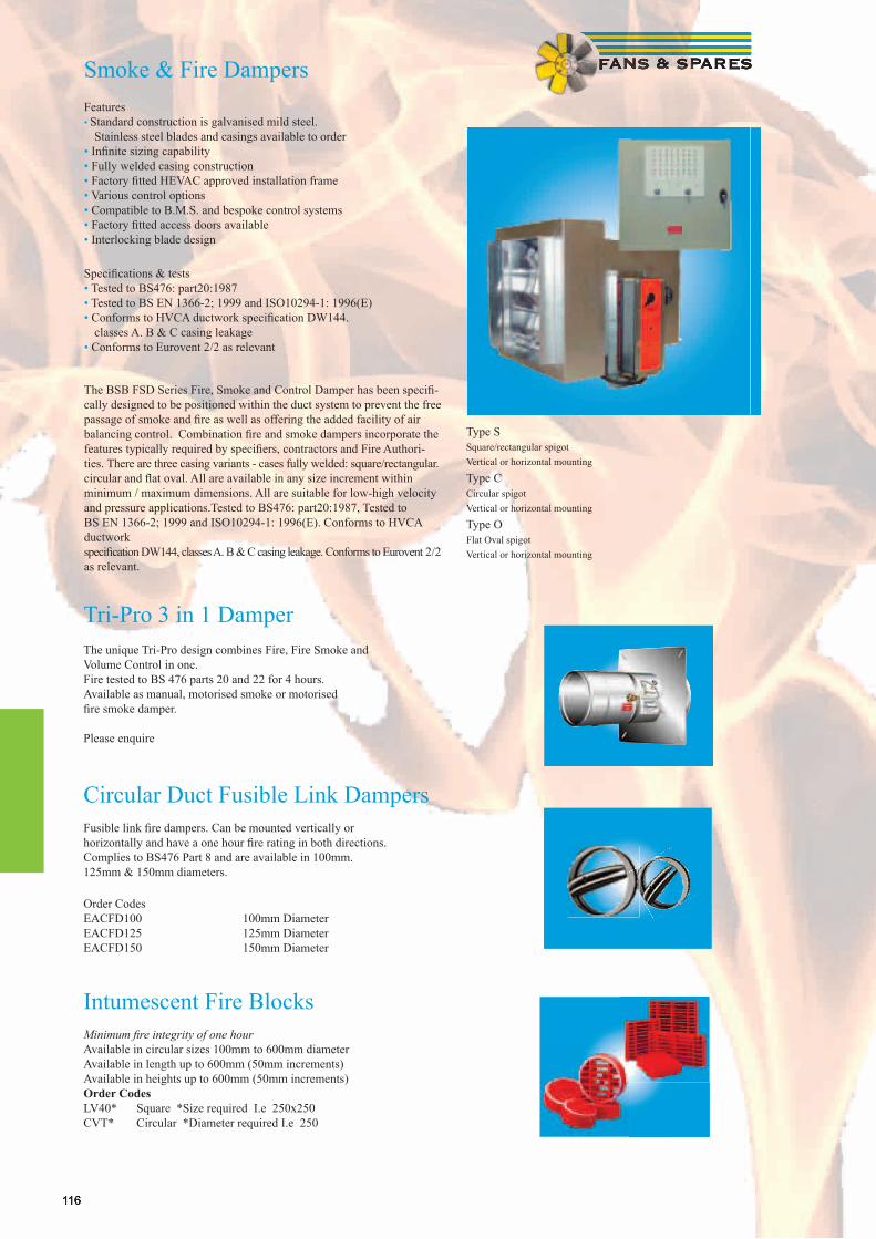
116116
Smoke & Fire DampersFeatures• Standard construction is galvanised mild steel. Stainless steel blades and casings available to order• Infi nite sizing capability• Fully welded casing construction• Factory fi tted HEVAC approved installation frame• Various control options• Compatible to B.M.S. and bespoke control systems• Factory fi tted access doors available• Interlocking blade design
Specifi cations & tests• Tested to BS476: part20:1987• Tested to BS EN 1366-2; 1999 and ISO10294-1: 1996(E)• Conforms to HVCA ductwork specifi cation DW144. classes A. B & C casing leakage• Conforms to Eurovent 2/2 as relevant
The BSB FSD Series Fire, Smoke and Control Damper has been specifi -cally designed to be positioned within the duct system to prevent the free passage of smoke and fi re as well as offering the added facility of air balancing control. Combination fi re and smoke dampers incorporate the features typically required by specifi ers, contractors and Fire Authori-ties. There are three casing variants - cases fully welded: square/rectangular. circular and fl at oval. All are available in any size increment within minimum / maximum dimensions. All are suitable for low-high velocity and pressure applications.Tested to BS476: part20:1987, Tested to BS EN 1366-2; 1999 and ISO10294-1: 1996(E). Conforms to HVCA ductwork specifi cation DW144, classes A. B & C casing leakage. Conforms to Eurovent 2/2 as relevant.
Type S Square/rectangular spigot Vertical or horizontal mounting
Type C Circular spigot Vertical or horizontal mounting
Type O Flat Oval spigot Vertical or horizontal mounting
Tri-Pro 3 in 1 Damper The unique Tri-Pro design combines Fire, Fire Smoke and Volume Control in one. Fire tested to BS 476 parts 20 and 22 for 4 hours. Available as manual, motorised smoke or motorised fi re smoke damper. Please enquire
Circular Duct Fusible Link Dampers Fusible link fi re dampers. Can be mounted vertically or horizontally and have a one hour fi re rating in both directions. Complies to BS476 Part 8 and are available in 100mm. 125mm & 150mm diameters. Order Codes EACFD100 100mm Diameter EACFD125 125mm Diameter EACFD150 150mm Diameter
Intumescent Fire Blocks Minimum fi re integrity of one hour Available in circular sizes 100mm to 600mm diameter Available in length up to 600mm (50mm increments) Available in heights up to 600mm (50mm increments) Order Codes LV40* Square *Size required I.e 250x250 CVT* Circular *Diameter required I.e 250
117
Ducting & Fittings
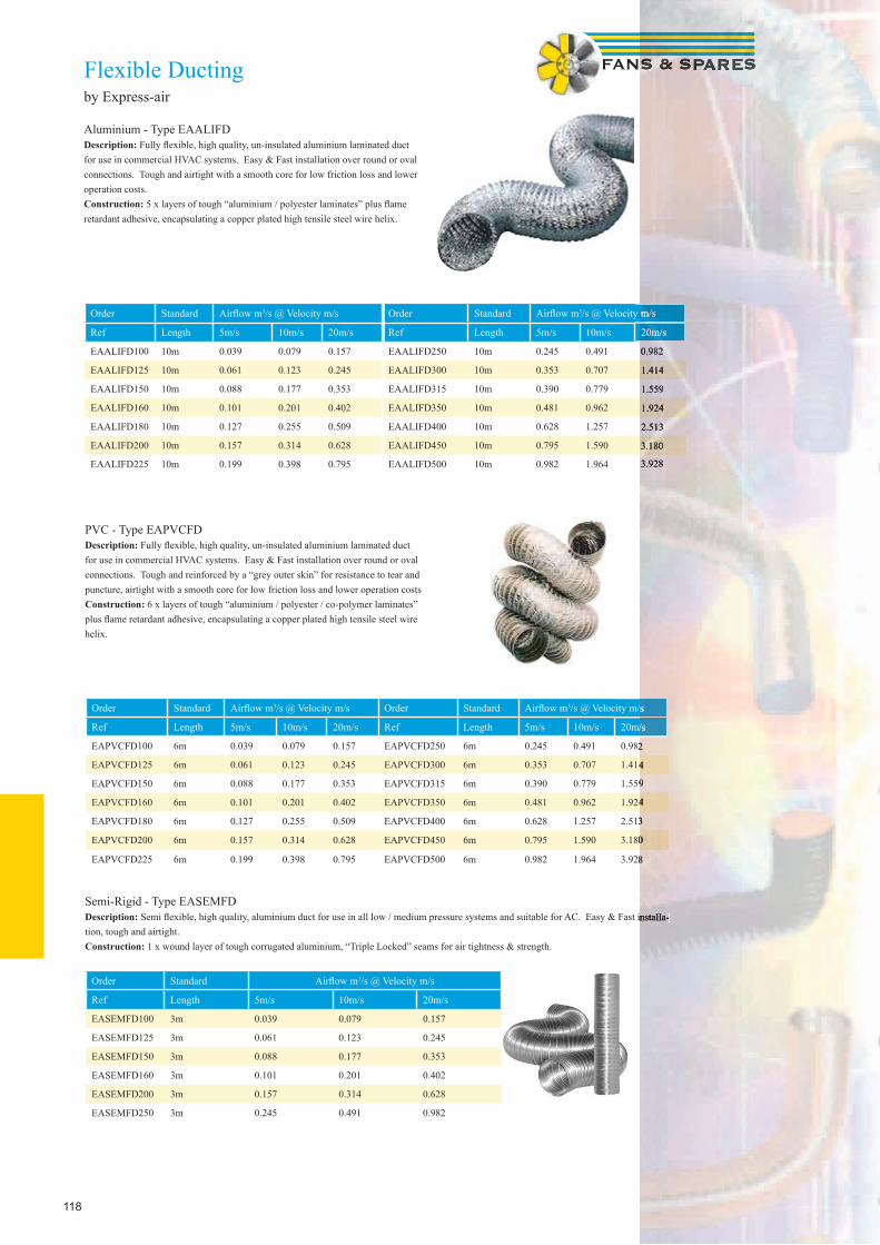
118
Flexible Ductingby Express-air
Aluminium - Type EAALIFDDescription: Fully fl exible, high quality, un-insulated aluminium laminated duct for use in commercial HVAC systems. Easy & Fast installation over round or oval connections. Tough and airtight with a smooth core for low friction loss and lower operation costs.Construction: 5 x layers of tough “aluminium / polyester laminates” plus fl ame retardant adhesive, encapsulating a copper plated high tensile steel wire helix.
Order Standard Airfl ow m3/s @ Velocity m/s Order Standard Airfl ow m3/s @ Velocity m/s
Ref Length 5m/s 10m/s 20m/s Ref Length 5m/s 10m/s 20m/s
EAPVCFD100 6m 0.039 0.079 0.157 EAPVCFD250 6m 0.245 0.491 0.982
EAPVCFD125 6m 0.061 0.123 0.245 EAPVCFD300 6m 0.353 0.707 1.414
EAPVCFD150 6m 0.088 0.177 0.353 EAPVCFD315 6m 0.390 0.779 1.559
EAPVCFD160 6m 0.101 0.201 0.402 EAPVCFD350 6m 0.481 0.962 1.924
EAPVCFD180 6m 0.127 0.255 0.509 EAPVCFD400 6m 0.628 1.257 2.513
EAPVCFD200 6m 0.157 0.314 0.628 EAPVCFD450 6m 0.795 1.590 3.180
EAPVCFD225 6m 0.199 0.398 0.795 EAPVCFD500 6m 0.982 1.964 3.928
Semi-Rigid - Type EASEMFDDescription: Semi fl exible, high quality, aluminium duct for use in all low / medium pressure systems and suitable for AC. Easy & Fast installa-tion, tough and airtight.Construction: 1 x wound layer of tough corrugated aluminium, “Triple Locked” seams for air tightness & strength.
Order Standard Airfl ow m3/s @ Velocity m/s
Ref Length 5m/s 10m/s 20m/s
EASEMFD100 3m 0.039 0.079 0.157
EASEMFD125 3m 0.061 0.123 0.245
EASEMFD150 3m 0.088 0.177 0.353
EASEMFD160 3m 0.101 0.201 0.402
EASEMFD200 3m 0.157 0.314 0.628
EASEMFD250 3m 0.245 0.491 0.982
PVC - Type EAPVCFDDescription: Fully fl exible, high quality, un-insulated aluminium laminated duct for use in commercial HVAC systems. Easy & Fast installation over round or oval connections. Tough and reinforced by a “grey outer skin” for resistance to tear and puncture, airtight with a smooth core for low friction loss and lower operation costsConstruction: 6 x layers of tough “aluminium / polyester / co-polymer laminates” plus fl ame retardant adhesive, encapsulating a copper plated high tensile steel wire helix.
Order Standard Airfl ow m3/s @ Velocity m/s Order Standard Airfl ow m3/s @ Velocity m/s
Ref Length 5m/s 10m/s 20m/s Ref Length 5m/s 10m/s 20m/s
EAALIFD100 10m 0.039 0.079 0.157 EAALIFD250 10m 0.245 0.491 0.982
EAALIFD125 10m 0.061 0.123 0.245 EAALIFD300 10m 0.353 0.707 1.414
EAALIFD150 10m 0.088 0.177 0.353 EAALIFD315 10m 0.390 0.779 1.559
EAALIFD160 10m 0.101 0.201 0.402 EAALIFD350 10m 0.481 0.962 1.924
EAALIFD180 10m 0.127 0.255 0.509 EAALIFD400 10m 0.628 1.257 2.513
EAALIFD200 10m 0.157 0.314 0.628 EAALIFD450 10m 0.795 1.590 3.180
EAALIFD225 10m 0.199 0.398 0.795 EAALIFD500 10m 0.982 1.964 3.928
/s @ Velocity m/s
20m/s
0.982
1.414
1.559
1.924
2.513
3.180
3.928
Semi fl exible, high quality, aluminium duct for use in all low / medium pressure systems and suitable for AC. Easy & Fast installa-
/s @ Velocity m/s
20m/s
0.982
1.414
1.559
1.924
2.513
3.180
3.928
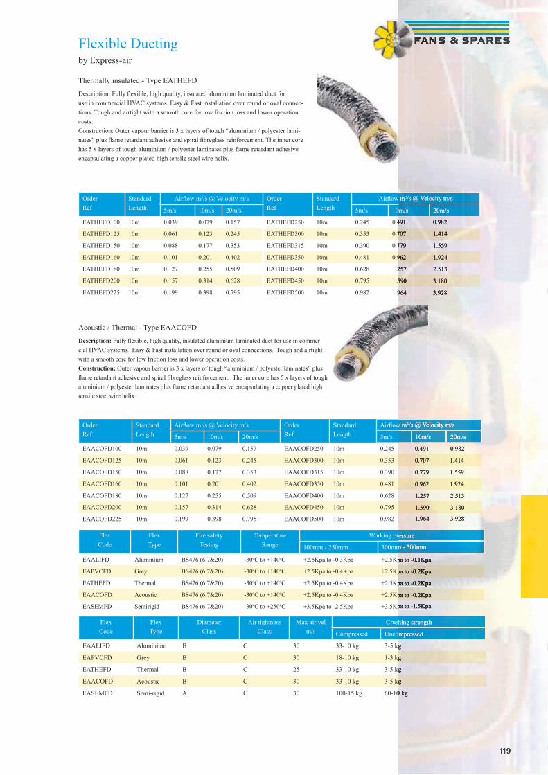
119
Order Ref
StandardLength
Airfl ow m3/s @ Velocity m/s Order Ref
StandardLength
Airfl ow m3/s @ Velocity m/s
5m/s 10m/s 20m/s 5m/s 10m/s 20m/s
EATHEFD100 10m 0.039 0.079 0.157 EATHEFD250 10m 0.245 0.491 0.982
EATHEFD125 10m 0.061 0.123 0.245 EATHEFD300 10m 0.353 0.707 1.414
EATHEFD150 10m 0.088 0.177 0.353 EATHEFD315 10m 0.390 0.779 1.559
EATHEFD160 10m 0.101 0.201 0.402 EATHEFD350 10m 0.481 0.962 1.924
EATHEFD180 10m 0.127 0.255 0.509 EATHEFD400 10m 0.628 1.257 2.513
EATHEFD200 10m 0.157 0.314 0.628 EATHEFD450 10m 0.795 1.590 3.180
EATHEFD225 10m 0.199 0.398 0.795 EATHEFD500 10m 0.982 1.964 3.928
Order Ref
StandardLength
Airfl ow m3/s @ Velocity m/s Order Ref
StandardLength
Airfl ow m3/s @ Velocity m/s
5m/s 10m/s 20m/s 5m/s 10m/s 20m/s
EAACOFD100 10m 0.039 0.079 0.157 EAACOFD250 10m 0.245 0.491 0.982
EAACOFD125 10m 0.061 0.123 0.245 EAACOFD300 10m 0.353 0.707 1.414
EAACOFD150 10m 0.088 0.177 0.353 EAACOFD315 10m 0.390 0.779 1.559
EAACOFD160 10m 0.101 0.201 0.402 EAACOFD350 10m 0.481 0.962 1.924
EAACOFD180 10m 0.127 0.255 0.509 EAACOFD400 10m 0.628 1.257 2.513
EAACOFD200 10m 0.157 0.314 0.628 EAACOFD450 10m 0.795 1.590 3.180
EAACOFD225 10m 0.199 0.398 0.795 EAACOFD500 10m 0.982 1.964 3.928
FlexCode
FlexType
Fire safetyTesting
TemperatureRange
Working pressure
100mm - 250mm 300mm - 500mm
EAALIFD Aluminium BS476 (6.7&20) -30ºC to +140ºC +2.5Kpa to -0.3Kpa +2.5Kpa to -0.1Kpa
EAPVCFD Grey BS476 (6.7&20) -30ºC to +140ºC +2.5Kpa to -0.4Kpa +2.5Kpa to -0.2Kpa
EATHEFD Thermal BS476 (6.7&20) -30ºC to +140ºC +2.5Kpa to -0.4Kpa +2.5Kpa to -0.2Kpa
EAACOFD Acoustic BS476 (6.7&20) -30ºC to +140ºC +2.5Kpa to -0.4Kpa +2.5Kpa to -0.2Kpa
EASEMFD Semirigid BS476 (6.7&20) -30ºC to +250ºC +3.5Kpa to -2.5Kpa +3.5Kpa to -1.5Kpa
FlexCode
FlexType
DiameterClass
Air tightnessClass
Max air velm/s
Crushing strength
Compressed Uncompressed
EAALIFD Aluminium B C 30 33-10 kg 3-5 kg
EAPVCFD Grey B C 30 18-10 kg 1-3 kg
EATHEFD Thermal B C 25 33-10 kg 3-5 kg
EAACOFD Acoustic B C 30 33-10 kg 3-5 kg
EASEMFD Semi-rigid A C 30 100-15 kg 60-10 kg
Acoustic / Thermal - Type EAACOFD
Description: Fully fl exible, high quality, insulated aluminium laminated duct for use in commer-cial HVAC systems. Easy & Fast installation over round or oval connections. Tough and airtight with a smooth core for low friction loss and lower operation costs.Construction: Outer vapour barrier is 3 x layers of tough “aluminium / polyester laminates” plus fl ame retardant adhesive and spiral fi breglass reinforcement. The inner core has 5 x layers of tough aluminium / polyester laminates plus fl ame retardant adhesive encapsulating a copper plated high tensile steel wire helix.
Flexible Ductingby Express-air
Thermally insulated - Type EATHEFD
Description: Fully fl exible, high quality, insulated aluminium laminated duct for use in commercial HVAC systems. Easy & Fast installation over round or oval connec-tions. Tough and airtight with a smooth core for low friction loss and lower operation costs.Construction: Outer vapour barrier is 3 x layers of tough “aluminium / polyester lami-nates” plus fl ame retardant adhesive and spiral fi breglass reinforcement. The inner core has 5 x layers of tough aluminium / polyester laminates plus fl ame retardant adhesive encapsulating a copper plated high tensile steel wire helix.
119
Airfl ow m3/s @ Velocity m/s
10m/s 20m/s
0.491 0.982
0.707 1.414
0.779 1.559
0.962 1.924
1.257 2.513
1.590 3.180
1.964 3.928
Airfl ow m3/s @ Velocity m/s
10m/s 20m/s
0.491 0.982
0.707 1.414
0.779 1.559
0.962 1.924
1.257 2.513
1.590 3.180
1.964 3.928
Working pressure
300mm - 500mm
+2.5Kpa to -0.1Kpa
+2.5Kpa to -0.2Kpa
+2.5Kpa to -0.2Kpa
+2.5Kpa to -0.2Kpa
+3.5Kpa to -1.5Kpa
Crushing strength
Uncompressed
3-5 kg
1-3 kg
3-5 kg
3-5 kg
60-10 kg
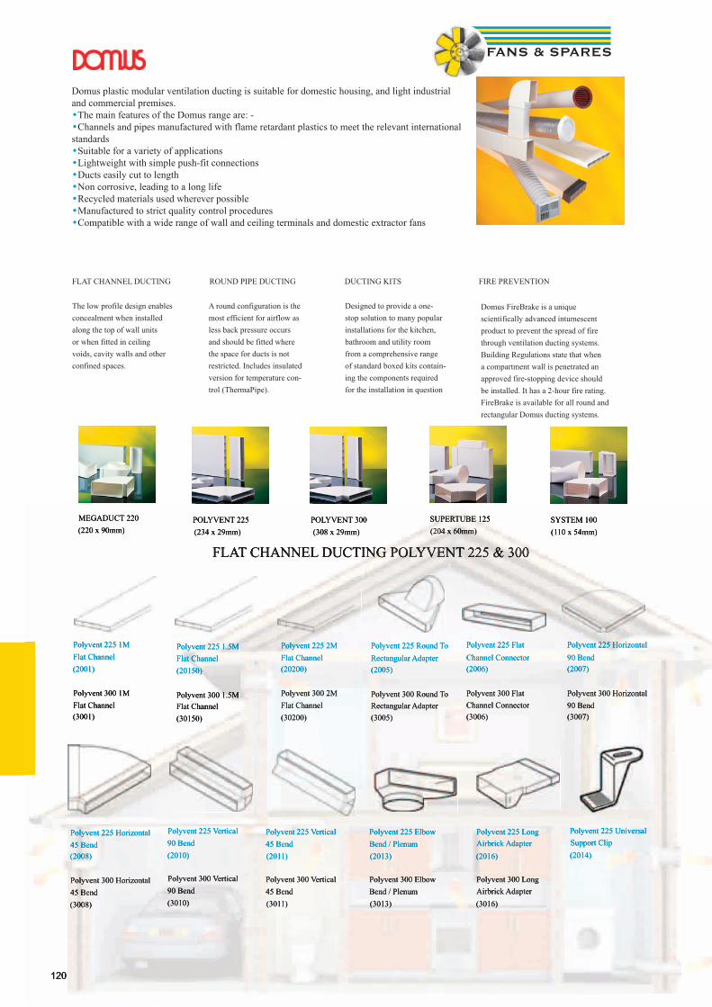
120
Domus plastic modular ventilation ducting is suitable for domestic housing, and light industrial and commercial premises.•The main features of the Domus range are: - •Channels and pipes manufactured with flame retardant plastics to meet the relevant international standards •Suitable for a variety of applications •Lightweight with simple push-fit connections •Ducts easily cut to length •Non corrosive, leading to a long life •Recycled materials used wherever possible •Manufactured to strict quality control procedures •Compatible with a wide range of wall and ceiling terminals and domestic extractor fans
The low profile design enables concealment when installed along the top of wall units or when fitted in ceiling voids, cavity walls and other confined spaces.
A round configuration is the most efficient for airflow as less back pressure occurs and should be fitted where the space for ducts is not restricted. Includes insulated version for temperature con-trol (ThermaPipe).
Designed to provide a one-stop solution to many popular installations for the kitchen, bathroom and utility room from a comprehensive range of standard boxed kits contain-ing the components required for the installation in question
Domus FireBrake is a unique scientifically advanced intumescent product to prevent the spread of fire through ventilation ducting systems. Building Regulations state that when a compartment wall is penetrated an approved fire-stopping device should be installed. It has a 2-hour fire rating. FireBrake is available for all round and rectangular Domus ducting systems.
FLAT CHANNEL DUCTING POLYVENT 225 & 300
MEGADUCT 220 (220 x 90mm)
POLYVENT 225 (234 x 29mm)
POLYVENT 300 (308 x 29mm)
SUPERTUBE 125 (204 x 60mm)
SYSTEM 100 (110 x 54mm)
FLAT CHANNEL DUCTING ROUND PIPE DUCTING DUCTING KITS FIRE PREVENTION
Polyvent 225 1M Flat Channel(2001)
Polyvent 300 1M Flat Channel(3001)
Polyvent 225 1.5M Flat Channel(20150)
Polyvent 300 1.5M Flat Channel(30150)
Polyvent 225 2M Flat Channel(20200)
Polyvent 300 2M Flat Channel(30200)
Polyvent 225 Round To Rectangular Adapter(2005)
Polyvent 300 Round To Rectangular Adapter(3005)
Polyvent 225 Flat Channel Connector(2006)
Polyvent 300 Flat Channel Connector(3006)
Polyvent 225 Horizontal 90 Bend(2007)
Polyvent 300 Horizontal 90 Bend(3007)
Polyvent 225 Horizontal 45 Bend(2008)
Polyvent 300 Horizontal 45 Bend(3008)
Polyvent 225 Vertical 90 Bend(2010)
Polyvent 300 Vertical 90 Bend(3010)
Polyvent 225 Vertical 45 Bend(2011)
Polyvent 300 Vertical 45 Bend(3011)
Polyvent 225 Elbow Bend / Plenum(2013)
Polyvent 300 Elbow Bend / Plenum(3013)
Polyvent 225 Long Airbrick Adapter(2016)
Polyvent 300 Long Airbrick Adapter(3016)
Polyvent 225 Universal Support Clip(2014)
120
FLAT CHANNEL DUCTING POLYVENT 225 & 300
MEGADUCT 220 (220 x 90mm)
POLYVENT 225 (234 x 29mm)
POLYVENT 300 (308 x 29mm)
SUPERTUBE 125 (204 x 60mm)
SYSTEM 100 (110 x 54mm)
Polyvent 225 1M Flat Channel(2001)
Polyvent 300 1M Flat Channel(3001)
Polyvent 225 1.5M Flat Channel(20150)
Polyvent 300 1.5M Flat Channel(30150)
Polyvent 225 2M Flat Channel(20200)
Polyvent 300 2M Flat Channel(30200)
Polyvent 225 Round To Rectangular Adapter(2005)
Polyvent 300 Round To Rectangular Adapter(3005)
Polyvent 225 Flat Channel Connector(2006)
Polyvent 300 Flat Channel Connector(3006)
Polyvent 225 Horizontal 90 Bend(2007)
Polyvent 300 Horizontal 90 Bend(3007)
Polyvent 225 Horizontal 45 Bend(2008)
Polyvent 300 Horizontal 45 Bend(3008)
Polyvent 225 Vertical 90 Bend(2010)
Polyvent 300 Vertical 90 Bend(3010)
Polyvent 225 Vertical 45 Bend(2011)
Polyvent 300 Vertical 45 Bend(3011)
Polyvent 225 Elbow Bend / Plenum(2013)
Polyvent 300 Elbow Bend / Plenum(3013)
Polyvent 225 Long Airbrick Adapter(2016)
Polyvent 300 Long Airbrick Adapter(3016)
Polyvent 225 Universal Support Clip(2014)

121
FLAT CHANNEL DUCTING MEGADUCT 220 (220 x 90mm)
MegaDuct 220 Flat Channel 1 metre 220 x 90mm(910)
MegaDuct 220 Flat Channel 1.5 metre 220 x 90mm(915)
MegaDuct 220 Flat Channel Connector(920)
MegaDuct Flat Channel Clip(922)
MegaDuct 220 Elbow Bend with rotating offset spigot 100mm Connection(941)
MegaDuct 220 Horizontal 90 deg Bend(950)
MegaDuct 220 Elbow Bend with rotating offset spigot 125mm Connection(951)
MegaDuct 220 Horizontal 45 deg Bend(955)
Supertube to MegaDuct Adapter(957)
MegaDuct 220 Vertical 90 deg Bend(960)
MegaDuct 220 Elbow Bend with rotating offset spigot 150mm Connection(961)
MegaDuct 220 Straight Round to Rectangular Adapter(970)
MegaDuct 220 Vertical 45 deg Bend(975)
Double Airbrick Adapter to MegaDuct 220(977)
010 System100 Flat Channel 1 metre
030 System100 Elbow Bend
070 System100 Round to Rectangu-lar Adapter
080 System100 Horizontal T Piece
015 System100 Flat Channel 1.5 metre
018 System100 Flat Channel End Cap
020 System100 Flat Channel Con-nector
027 System100 Flat Channel Con-nector with Damper
040 System100 Elbow Bend with Spigot
050 System100 Horizontal 90 deg Bend
055 System100 Horizontal 45 deg Bend
060 System100 Vertical 90 deg Bend
071 System100 Short Round to Rectangular Adapter
073 100mm Round to single Air-brick Adapter
075 System100 Vertical 45 deg Bend
077 Airbrick Adapter to System100
107 System100 Damper Valve with Wall Plate
115-4 System 100 Rectangular Wall Plate
122-4 System100 Flat Channel Clip
D1-2000 System100 Flat Channel 2metre
FLAT CHANNEL DUCTING SYSTEM 100 (110 x 54mm)
MegaDuct 220 Horizontal 90 deg Bend(950)
MegaDuct 220 Elbow Bend with rotating offset spigot 125mm Connection(951)
MegaDuct 220 Horizontal 45 deg Bend(955)
Supertube to MegaDuct Adapter(957)
MegaDuct 220 Vertical 90 deg Bend(960)
MegaDuct 220 Elbow Bend with rotating offset spigot 150mm Connection(961)
MegaDuct 220 Straight Round to Rectangular Adapter(970)
MegaDuct 220 Vertical 45 deg Bend(975)
Double Airbrick Adapter to MegaDuct 220(977)
010 System100 Flat Channel 1 metre
030 System100 Elbow Bend
070 System100 Round to Rectangu-lar Adapter
080 System100 Horizontal T Piece
015 System100 Flat Channel 1.5 metre
018 System100 Flat Channel End Cap
020 System100 Flat Channel Con-nector
040 System100 Elbow Bend with Spigot
050 System100 Horizontal 90 deg Bend
055 System100 Horizontal 45 deg Bend
071 System100 Short Round to Rectangular Adapter
073 100mm Round to single Air-brick Adapter
075 System100 Vertical 45 deg Bend
107 System100 Damper Valve with
115-4 System 100 Rectangular Wall
122-4 System100 Flat Channel Clip
FLAT CHANNEL DUCTING SYSTEM 100 (110 x 54mm)
087 System 100 FireBrake Duct Con-nector
2087 PolyVent 225 FireBrake Duct Con-nector
3087 PolyVent 300 FireBrake Duct Con-nector
488 EasiPipe 100 FireBrake Duct Con-nector
587 Supertube 125 FireBrake Duct Con-nector
987 MegaDuct 220 FireBrake Duct Con-nector
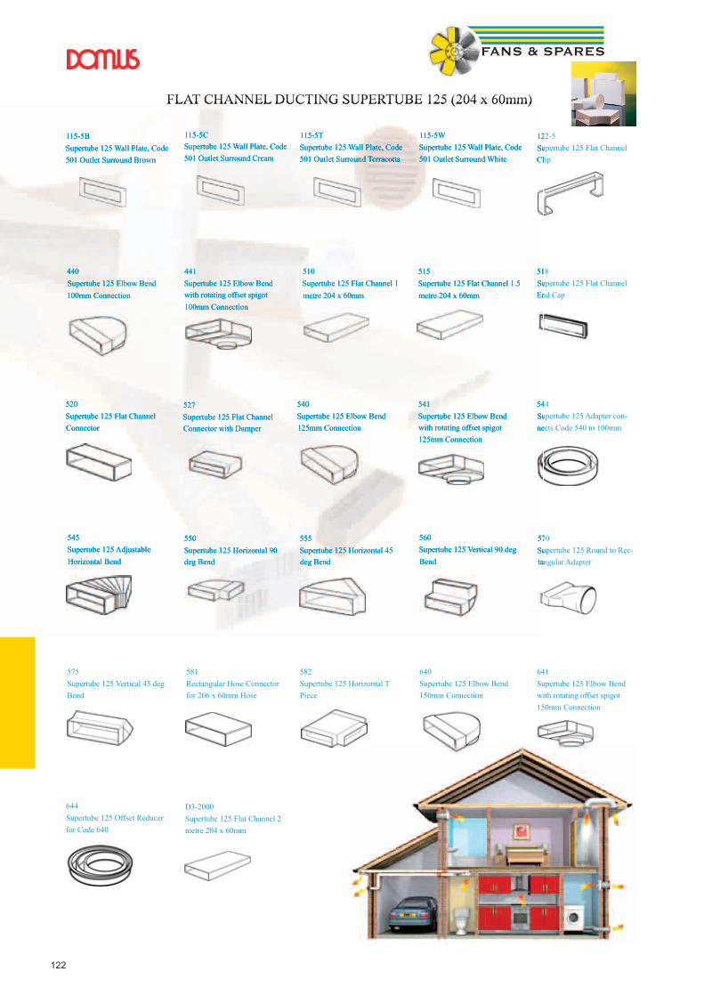
122
FLAT CHANNEL DUCTING SUPERTUBE 125 (204 x 60mm)
115-5B Supertube 125 Wall Plate, Code 501 Outlet Surround Brown
115-5C Supertube 125 Wall Plate, Code 501 Outlet Surround Cream
115-5T Supertube 125 Wall Plate, Code 501 Outlet Surround Terracotta
115-5W Supertube 125 Wall Plate, Code 501 Outlet Surround White
122-5 Supertube 125 Flat Channel Clip
440 Supertube 125 Elbow Bend 100mm Connection
441 Supertube 125 Elbow Bend with rotating offset spigot 100mm Connection
510 Supertube 125 Flat Channel 1 metre 204 x 60mm
515 Supertube 125 Flat Channel 1.5 metre 204 x 60mm
518 Supertube 125 Flat Channel End Cap
520 Supertube 125 Flat Channel Connector
527 Supertube 125 Flat Channel Connector with Damper
540 Supertube 125 Elbow Bend 125mm Connection
541 Supertube 125 Elbow Bend with rotating offset spigot 125mm Connection
544 Supertube 125 Adapter con-nects Code 540 to 100mm
545 Supertube 125 Adjustable Horizontal Bend
550 Supertube 125 Horizontal 90 deg Bend
555 Supertube 125 Horizontal 45 deg Bend
560 Supertube 125 Vertical 90 deg Bend
570 Supertube 125 Round to Rec-tangular Adapter
575 Supertube 125 Vertical 45 deg Bend
581 Rectangular Hose Connector for 206 x 60mm Hose
582 Supertube 125 Horizontal T Piece
640 Supertube 125 Elbow Bend 150mm Connection
641 Supertube 125 Elbow Bend with rotating offset spigot 150mm Connection
644 Supertube 125 Offset Reducer for Code 640
D3-2000 Supertube 125 Flat Channel 2 metre 204 x 60mm
FLAT CHANNEL DUCTING SUPERTUBE 125 (204 x 60mm)
115-5B Supertube 125 Wall Plate, Code 501 Outlet Surround Brown
115-5C Supertube 125 Wall Plate, Code 501 Outlet Surround Cream
115-5T Supertube 125 Wall Plate, Code 501 Outlet Surround Terracotta
115-5W Supertube 125 Wall Plate, Code 501 Outlet Surround White
122-5 Supertube 125 Flat Channel Clip
440 Supertube 125 Elbow Bend 100mm Connection
441 Supertube 125 Elbow Bend with rotating offset spigot 100mm Connection
510 Supertube 125 Flat Channel 1 metre 204 x 60mm
515 Supertube 125 Flat Channel 1.5 metre 204 x 60mm
518 Supertube 125 Flat Channel End Cap
520 Supertube 125 Flat Channel Connector
527 Supertube 125 Flat Channel Connector with Damper
540 Supertube 125 Elbow Bend 125mm Connection
541 Supertube 125 Elbow Bend with rotating offset spigot 125mm Connection
544 Supertube 125 Adapter con-nects Code 540 to 100mm
545 Supertube 125 Adjustable Horizontal Bend
550 Supertube 125 Horizontal 90 deg Bend
555 Supertube 125 Horizontal 45 deg Bend
560 Supertube 125 Vertical 90 deg Bend
570 Supertube 125 Round to Rec-tangular Adapter

123
019 Circular Adapter 80/100mm119 Circular Adapter 100/125mm118 Circular Adapter 125/150mm
1100-4 EasiPipe 100 Round Pipe 1M - 100mm dia1100-5 EasiPipe 125 Round Pipe 1M - 125mm dia1100-6 EasiPipe 150 Round Pipe 1M - 150mm dia
114-4 Round Wall Plate for 100mm Hose or Pipe114-5 Round Wall Plate for 125mm Hose or Pipe114-6 Round Wall Plate for 150mm Hose or Pipe
120 Aluminium Reducing Piece 110mm to 100mm
1200-4 EasiPipe 100 Round Pipe 2M - 100mm dia1200-5 EasiPipe 125 Round Pipe 2M - 125mm dia1200-6 EasiPipe 150 Round Pipe 2M150mm dia
130-4 Telescopic Pipe 100mm dia 250 to 450mm long130-5 Telescopic Pipe 125mm dia 250 to 450mm130-6 Telescopic Pipe 150mm dia 250 to 450mm
135-4 Round Pipe Inner dia 100mm 350mm long135-5 Round Pipe Inner dia 125mm 350mm135-6 Round Pipe Inner dia 150mm 350mm
2100-4 Outer Sleeve for 100mm Round Pipe 1M2100-5 Inner Pipe for 125mm Round Pipe 1M2100-6 Inner Pipe for 150mm Round Pipe 1M
490 EasiPipe100 Right Angle Bend590 EasiPipe 125 Round 90 Degree Bend690 EasiPipe 150 Round 90 Degree Bend
491 EasiPipe100 45 Degree Bend591 Easipipe 125 45 Bend
150mm Dia not available
492 Equal T Piece 100mm592 EasiPipe 125 Equal ‘T’ Piece692M 150mm Equal ‘T’ Piece - White metal
493 100mm EasiPipe 100 Straight Pipe Connector593 EasiPipe 125 Straight Pipe Connector693 EasiPipe 150 Straight Pipe Connector
494 100mm EasiPipe 100 Straight Pipe Connector c/w Damper594 EasiPipe 125 Straight Pipe Connector c/w Damper694 EasiPipe 150 Straight Pipe Connector c/w Damper
495 100mm EasiPipe Straight Pipe Connector c/w Damper & Wall Plate595 EasiPipe 125 Straight Pipe Connector c/w Damper & Wall Plate695 EasiPipe 150 Connector with Valve and Wall Plate
496 EasiPipe100 Fixing Clip596 EasiPipe125 Fixing Clip696 EasiPipe150 Fixing Clip
497 Condensation Trap 100-110mm with Overflow Connection
498 Condensation Trap 100-110mm
499M EasiPipe 100 Equal ‘Y’ Piece - White metal599M EasiPipe 125 125mm Equal ‘Y’ Piece - White metal699M 150mm Equal ‘Y’ Piece - White metal
ROUND PIPE DUCTING EASIPIPE 100 (100mm) / EASIPIPE 125 (125mm) / EASIPIPE 150 (150mm)
123
EasiPipe 125 125mm Equal ‘Y’ Piece - White metal
150mm Equal ‘Y’ Piece - White metal
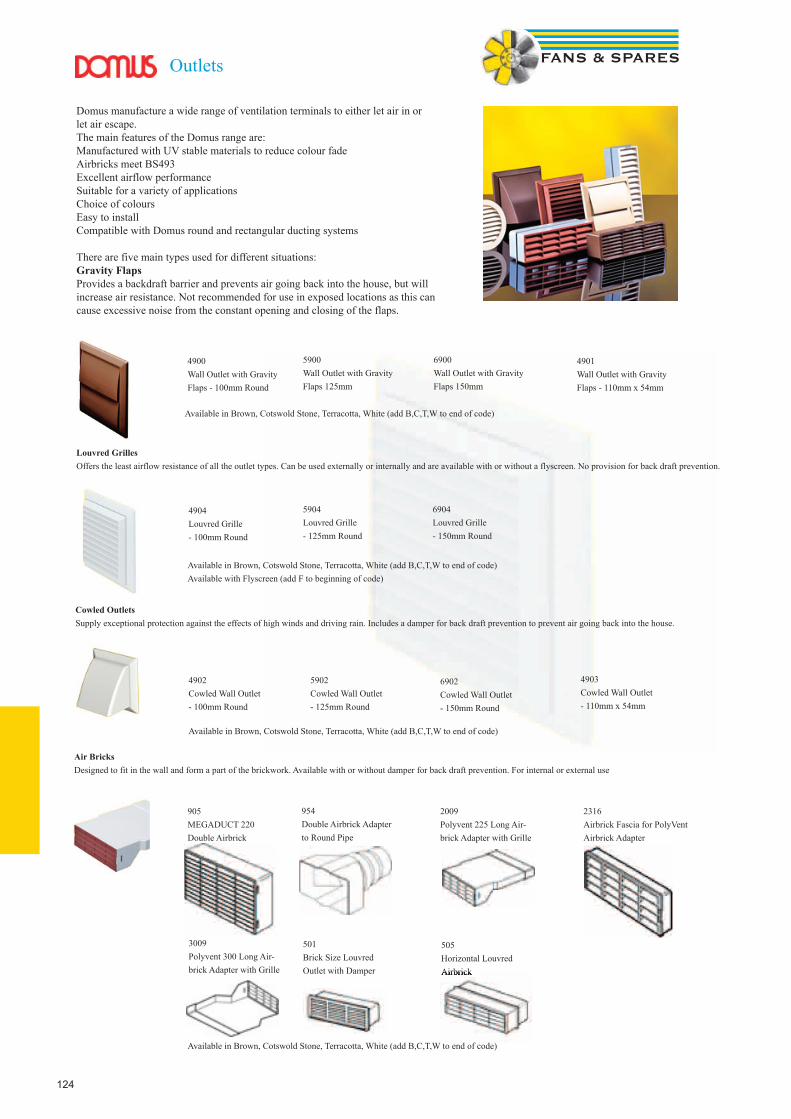
124
Domus manufacture a wide range of ventilation terminals to either let air in or let air escape.The main features of the Domus range are: Manufactured with UV stable materials to reduce colour fade Airbricks meet BS493 Excellent airflow performance Suitable for a variety of applications Choice of colours Easy to install Compatible with Domus round and rectangular ducting systems
There are five main types used for different situations:Gravity FlapsProvides a backdraft barrier and prevents air going back into the house, but will increase air resistance. Not recommended for use in exposed locations as this can cause excessive noise from the constant opening and closing of the flaps.
Outlets
4900 Wall Outlet with Gravity Flaps - 100mm Round
5900 Wall Outlet with Gravity Flaps 125mm
6900 Wall Outlet with Gravity Flaps 150mm
4901 Wall Outlet with Gravity Flaps - 110mm x 54mm
Available in Brown, Cotswold Stone, Terracotta, White (add B,C,T,W to end of code)
4904 Louvred Grille- 100mm Round
5904 Louvred Grille- 125mm Round
6904 Louvred Grille- 150mm Round
Available in Brown, Cotswold Stone, Terracotta, White (add B,C,T,W to end of code)Available with Flyscreen (add F to beginning of code)
Louvred GrillesOffers the least airflow resistance of all the outlet types. Can be used externally or internally and are available with or without a flyscreen. No provision for back draft prevention.
Cowled OutletsSupply exceptional protection against the effects of high winds and driving rain. Includes a damper for back draft prevention to prevent air going back into the house.
Air BricksDesigned to fit in the wall and form a part of the brickwork. Available with or without damper for back draft prevention. For internal or external use
4903Cowled Wall Outlet - 110mm x 54mm
4902Cowled Wall Outlet - 100mm Round
5902Cowled Wall Outlet - 125mm Round
6902Cowled Wall Outlet - 150mm Round
Available in Brown, Cotswold Stone, Terracotta, White (add B,C,T,W to end of code)
905MEGADUCT 220Double Airbrick
954Double Airbrick Adapter to Round Pipe
2009Polyvent 225 Long Air-brick Adapter with Grille
2316Airbrick Fascia for PolyVent Airbrick Adapter
3009Polyvent 300 Long Air-brick Adapter with Grille
501Brick Size Louvred Outlet with Damper
505Horizontal Louvred AirbrickAirbrick
Available in Brown, Cotswold Stone, Terracotta, White (add B,C,T,W to end of code)
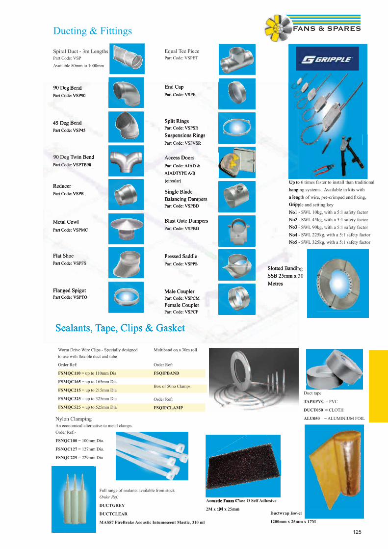
125
Ducting & Fittings
Spiral Duct - 3m LengthsPart Code: VSP
Available 80mm to 1000mm
90 Deg BendPart Code: VSP90
45 Deg BendPart Code: VSP45
90 Deg Twin BendPart Code: VSPTB90
ReducerPart Code: VSPR
Metal CowlPart Code: VSPMC
Flat ShoePart Code: VSPFS
Flanged SpigotPart Code: VSPTO
Equal Tee PiecePart Code: VSPET
End CapPart Code: VSPE
Split RingsPart Code: VSPSR
Suspensions RingsPart Code: VSPVSR
Access DoorsPart Code: AJAD &
AJADTYPE A/B
(circular)
Single Blade Balancing DampersPart Code: VSPBD
Blast Gate DampersPart Code: VSPBG
Pressed SaddlePart Code: VSPPS
Male CouplerPart Code: VSPCM
Female CouplerPart Code: VSPCF
Up to 6 times faster to install than traditional hanging systems. Available in kits with a length of wire, pre-crimped end fi xing, Gripple and setting key No1 - SWL 10kg, with a 5:1 safety factor No2 - SWL 45kg, with a 5:1 safety factor No3 - SWL 90kg, with a 5:1 safety factor No4 - SWL 225kg, with a 5:1 safety factor No5 - SWL 325kg, with a 5:1 safety factor
Slotted BandingSSB 25mm x 30 Metres
Sealants, Tape, Clips & Gasket
Worm Drive Wire Clips - Specially designed to use with fl exible duct and tube
Multiband on a 30m roll
Order Ref:
FSMQC110 = up to 110mm Dia
FSMQC165 = up to 165mm Dia
FSMQC215 = up to 215mm Dia
FSMQC325 = up to 325mm Dia
FSMQC525 = up to 525mm Dia
Order Ref:
FSQIPBAND
Box of 50no Clamps
Order Ref:
FSQIPCLAMP
Duct tape
TAPEPVC = PVC
DUCT050 = CLOTH
ALU050 = ALUMINIUM FOILNylon ClampingAn economical alternative to metal clamps. Order Ref:-
FSNQC100 = 100mm Dia.
FSNQC127 = 127mm Dia.
FSNQC229 = 229mm Dia
Full range of sealants available from stockOrder Ref:
DUCTGREY
DUCTCLEAR
MAS87 FireBrake Acoustic Intumescent Mastic, 310 ml
Ductwrap Isover
1200mm x 25mm x 17M
Acoustic Foam Class O Self Adhesive
2M x 1M x 25mm
Acoustic Foam Class O Self Adhesive
2M x 1M x 25mm
90 Deg BendPart Code: VSP90Part Code: VSP90Part
45 Deg BendPart Code: VSP45Part Code: VSP45Part
90 Deg Twin BendPart Code: VSPTB90Part Code: VSPTB90Part
ReducerPart Code: VSPRPart Code: VSPRPart
Metal CowlPart Code: VSPMCPart Code: VSPMCPart
Flat ShoePart Code: Part Code: Part VSPFS
Flanged SpigotPart Code: Part Code: Part VSPTO
End CapPart Code: VSPEPart Code: VSPEPart
Split RingsPart Code: VSPSRPart Code: VSPSRPart
Suspensions RingsPart Code: VSPPart Code: VSPPart VSR
Access DoorsPart Code: AJAD &Part Code: AJAD &Part
AJADTYPE A/B
(circular)
Single Blade Balancing DampersPart Code: VSPBDPart Code: VSPBDPart
Blast Gate DampersPart Code: VSPBGPart Code: VSPBGPart
Pressed SaddlePart Code: Part Code: Part VSPPS
Male CouplerPart Code: Part Code: Part VSPCM
Female CouplerPart Code: VSPPart Code: VSPPart CF
Up to 6 times faster to install than traditional hanging systems. Available in kits with a length of wire, pre-crimped end fi xing, Gripple and setting key No1 - SWL 10kg, with a 5:1 safety factor No2 - SWL 45kg, with a 5:1 safety factor No3 - SWL 90kg, with a 5:1 safety factor No4 - SWL 225kg, with a 5:1 safety factor No5 - SWL 325kg, with a 5:1 safety factor
Slotted BandingSSB 25mm x 30 Metres
Sealants, Tape, Clips & Gasket

126
Controls & SensorsSensors

127
Auto transformer 5 step speed controlsRE - Single Phase Auto Transformer
Amps Fuse H x W x D mm kg
RE 1.5 1.5A 1.8A 200x105x105 1.5
RE 3 3A 3.5A 200x105x105 2.5
RE 5 5A 6A 200x105x105 4.1
RE 7 7A 8A 275x105x145 7.5
RTRE - Single Phase Auto Transformer with TK’sFuse H x W x D mm kg
RTRE 1.5 1.5A 1.8A 200x105x105 1.6
RTRE 3 3A 3.5A 200x105x105 2.6
RTRE 5 5A 6A 200x105x105 4.2
RTRE 7 7A 8A 275x105x145 7.6
RTRE 12 12A 12A 256x147x140 10.5
RTRD - Three Phase Auto Transformer with TK’sAmps Fuse H x W x D mm kg
RTRD 2 2A - 255x190x135 7.5
RTRD 4 4A - 309x262x160
RTRD 7 7A - 309x262x160 18
RTRD 14 14A - 290x400x166 30
Output voltages for each of the 5 steps
Steps 1 2 3 4 5
Voltage V 95 145 190 240 400
Output voltages for each of the 5 steps
Steps 1 2 3 4 5
Voltage V 80 105 130 160 230
Multi-Unit Speed ControlIf multiple fans are to be run off one Auto transformer speed control, then the total combined full load currents (FLC) of the fans, plus a 20% margin must not exceed the Amperage of the controller. All TK’s must be wired in series or Fans without TK’s will each require a motor protection device. STET 10B. Example 4 no KDRD50 Fan off 1 no RTRD Full load current of fan 0.98amps multiplied by 4 = 3.92amps Plus 20% = 4.7ampsTherefore speed controller required is RTRD 7 (7amps)
Output voltages for each of the 5 steps
Steps 1 2 3 4 5
Voltage V 80 105 130 160 230
A single-phase transformer which controls the fan speed by alter-ing the supply voltage in five fixed steps. The steps are adjusted manually, using the control knob on the front of the unit. The transformer has 230V terminals for operating dampers, electric heater batteries or other external equipment. When the transform-er knob is in position 0, the outlet has no current. The indicator lamp on the front shows that the transformer is in operation. The fuse may be reset from outside. The RE has a self extinguishing thermoplastic casing.
A single-phase transformer which controls the fan speed by alter-ing the supply voltage in five fixed steps. The steps are adjusted manually, using the control knob on the front of the unit. An integral motor protection device is included which cuts the supply voltage to the fan if the thermal contact in the fan motor is acti-vated. The unit is reset by turning the knob to “0” for 10 seconds, after which the unit restarts.The unit has input terminals for room thermostat RT, which stops the supply voltage to the fan when the circuit is broken. These terminals are linked before delivery. The transformer has 230V terminals for operating dampers, electric water-heater batteries or other external equipment.
A three-phase transformer which controls the fan speed by altering the supply voltage in five fixed steps. The steps are adjusted manually, us-ing the control knob on the front of the unit.An integral motor protection device is included which cuts the supply voltage to the fan if the thermal contact in the fan motor is activated. The unit is reset by turning the knob to “0” for 10 seconds, after which the unit restarts. Input terminals for room thermostat RT and frost protection thermostat FS cut supply voltage to the fan when the circuit is broken. When the frost protection thermostat FS breaks the circuit, it is reset in the same way as when the TK is triggered. Terminals are linked before delivery. The indicator lamp on the front shows that the transformer is in opera-tion. The transformer has 230V terminals for operating dampers, electric heater batteries or other external equipment. These terminals have no current when the transformer knob is in position 0, or when the TK or RT input is open. Supply voltage: 400V 50/60Hz.
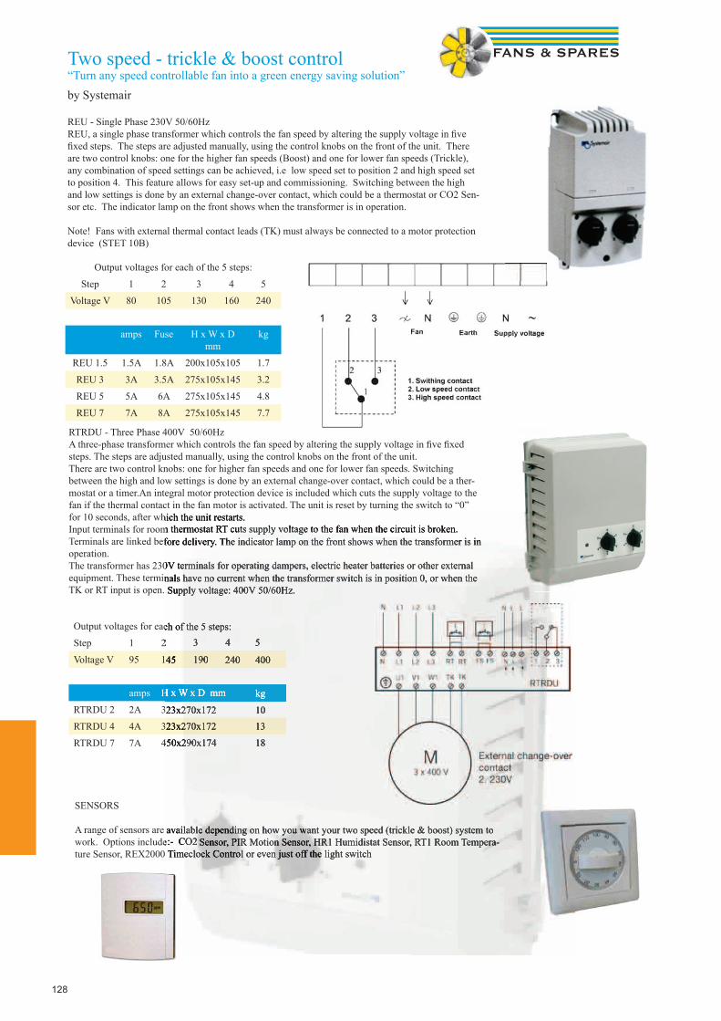
128
Two speed - trickle & boost control“Turn any speed controllable fan into a green energy saving solution”by Systemair
REU - Single Phase 230V 50/60HzREU, a single phase transformer which controls the fan speed by altering the supply voltage in fi ve fi xed steps. The steps are adjusted manually, using the control knobs on the front of the unit. There are two control knobs: one for the higher fan speeds (Boost) and one for lower fan speeds (Trickle), any combination of speed settings can be achieved, i.e low speed set to position 2 and high speed set to position 4. This feature allows for easy set-up and commissioning. Switching between the high and low settings is done by an external change-over contact, which could be a thermostat or CO2 Sen-sor etc. The indicator lamp on the front shows when the transformer is in operation.
Note! Fans with external thermal contact leads (TK) must always be connected to a motor protection device (STET 10B)
Output voltages for each of the 5 steps:
Step 1 2 3 4 5
Voltage V 80 105 130 160 240
amps Fuse H x W x D mm
kg
REU 1.5 1.5A 1.8A 200x105x105 1.7
REU 3 3A 3.5A 275x105x145 3.2
REU 5 5A 6A 275x105x145 4.8
REU 7 7A 8A 275x105x145 7.7
RTRDU - Three Phase 400V 50/60HzA three-phase transformer which controls the fan speed by altering the supply voltage in fi ve fi xed steps. The steps are adjusted manually, using the control knobs on the front of the unit.There are two control knobs: one for higher fan speeds and one for lower fan speeds. Switching between the high and low settings is done by an external change-over contact, which could be a ther-mostat or a timer.An integral motor protection device is included which cuts the supply voltage to the fan if the thermal contact in the fan motor is activated. The unit is reset by turning the switch to “0” for 10 seconds, after which the unit restarts.Input terminals for room thermostat RT cuts supply voltage to the fan when the circuit is broken. Terminals are linked before delivery. The indicator lamp on the front shows when the transformer is in operation.The transformer has 230V terminals for operating dampers, electric heater batteries or other external equipment. These terminals have no current when the transformer switch is in position 0, or when the TK or RT input is open. Supply voltage: 400V 50/60Hz.
Output voltages for each of the 5 steps:
Step 1 2 3 4 5
Voltage V 95 145 190 240 400
amps H x W x D mm kg
RTRDU 2 2A 323x270x172 10
RTRDU 4 4A 323x270x172 13
RTRDU 7 7A 450x290x174 18
SENSORS
A range of sensors are available depending on how you want your two speed (trickle & boost) system to work. Options include:- CO2 Sensor, PIR Motion Sensor, HR1 Humidistat Sensor, RT1 Room Tempera-ture Sensor, REX2000 Timeclock Control or even just off the light switch
for 10 seconds, after which the unit restarts.Input terminals for room thermostat RT cuts supply voltage to the fan when the circuit is broken. Terminals are linked before delivery. The indicator lamp on the front shows when the transformer is in
The transformer has 230V terminals for operating dampers, electric heater batteries or other external equipment. These terminals have no current when the transformer switch is in position 0, or when the TK or RT input is open. Supply voltage: 400V 50/60Hz.
Output voltages for each of the 5 steps:
2 3 4 5
145 190 240 400
H x W x D mm kg
323x270x172 10
323x270x172 13
450x290x174 18
A range of sensors are available depending on how you want your two speed (trickle & boost) system to Options include:- CO2 Sensor, PIR Motion Sensor, HR1 Humidistat Sensor, RT1 Room Tempera-
REX2000 Timeclock Control or even just off the light switch
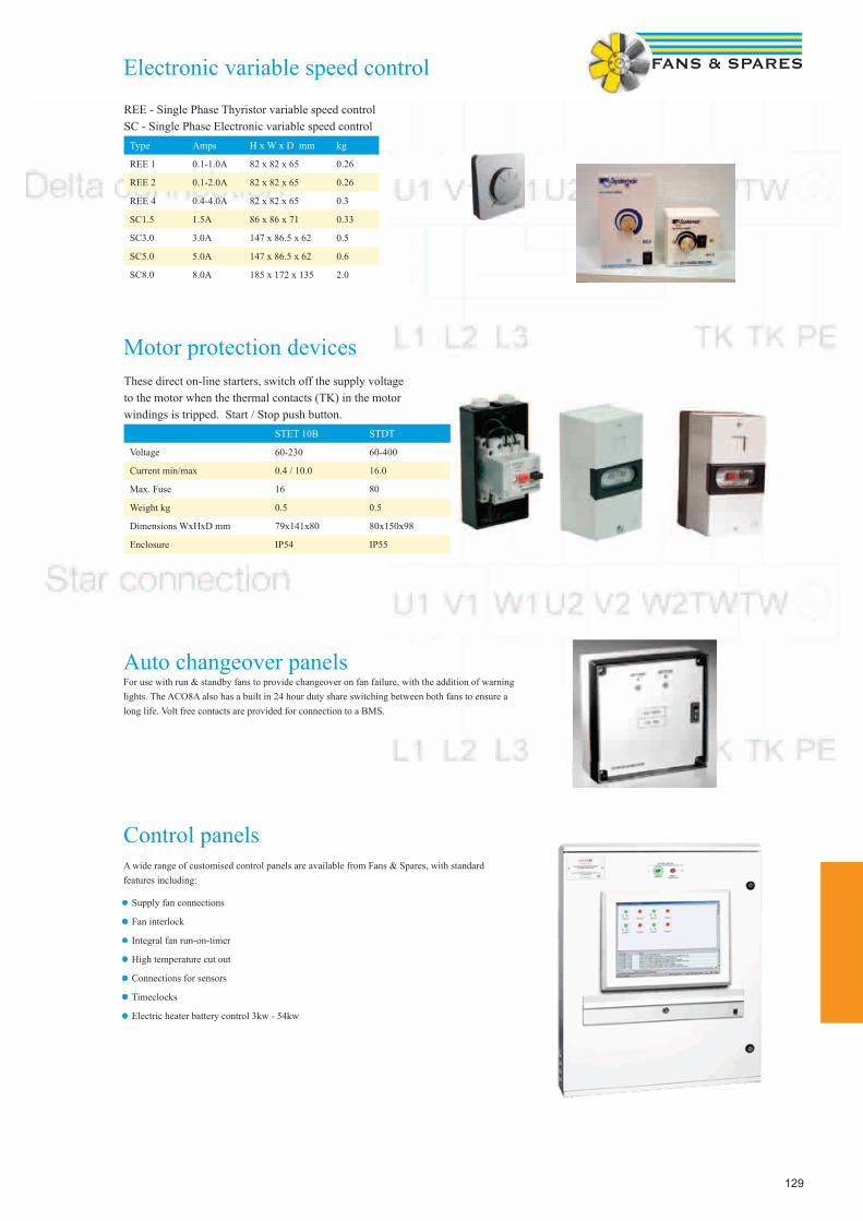
129
Electronic variable speed control
Motor protection devices
Auto changeover panelsFor use with run & standby fans to provide changeover on fan failure, with the addition of warning lights. The ACO8A also has a built in 24 hour duty share switching between both fans to ensure a long life. Volt free contacts are provided for connection to a BMS.
Control panelsA wide range of customised control panels are available from Fans & Spares, with standard features including:
• Supply fan connections
• Fan interlock
• Integral fan run-on-timer
• High temperature cut out
• Connections for sensors
• Timeclocks
• Electric heater battery control 3kw - 54kw
REE - Single Phase Thyristor variable speed controlSC - Single Phase Electronic variable speed control
Type Amps H x W x D mm kg
REE 1 0.1-1.0A 82 x 82 x 65 0.26
REE 2 0.1-2.0A 82 x 82 x 65 0.26
REE 4 0.4-4.0A 82 x 82 x 65 0.3
SC1.5 1.5A 86 x 86 x 71 0.33
SC3.0 3.0A 147 x 86.5 x 62 0.5
SC5.0 5.0A 147 x 86.5 x 62 0.6
SC8.0 8.0A 185 x 172 x 135 2.0
These direct on-line starters, switch off the supply voltage to the motor when the thermal contacts (TK) in the motor windings is tripped. Start / Stop push button.
STET 10B STDT
Voltage 60-230 60-400
Current min/max 0.4 / 10.0 16.0
Max. Fuse 16 80
Weight kg 0.5 0.5
Dimensions WxHxD mm 79x141x80 80x150x98
Enclosure IP54 IP55

130
Sensors & Controlsby Express-air
EAC6:Variable speed control suitable for all “size 6”Express-air commercial fans
EAC9/12:Variable speed control with reversible switchsuitable for all “size 9 & 12” Express-aircommercial fans
EFS-PIR:Remote Passive Infra Red motion detector360 deg vision. with built in Run on Timer
EFS-ROT:Remote Run on Timer 1-20 mins
EFS-7DAY:Remote Analogue 7 Day Timeswitch
EFS-HS:Remote Humidistat 40% - 95% RH
Other Sensors & Controls availablePlease enquire
Air Quality SensorsCO2 SensorsIsolator SwitchDifferential Pressure SwitchDigital Time Clocks
RT 0-30:Remote Room Thermostat 0 - 30 degC
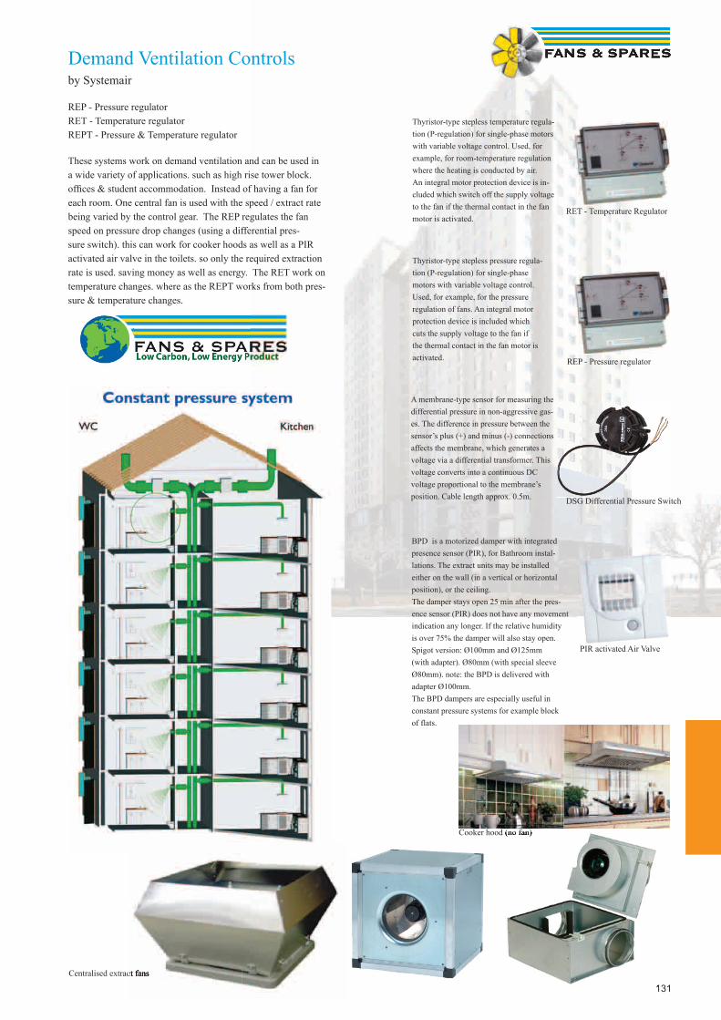
131
Demand Ventilation Controlsby Systemair
REP - Pressure regulatorRET - Temperature regulatorREPT - Pressure & Temperature regulator
These systems work on demand ventilation and can be used in a wide variety of applications. such as high rise tower block. offi ces & student accommodation. Instead of having a fan for each room. One central fan is used with the speed / extract rate being varied by the control gear. The REP regulates the fan speed on pressure drop changes (using a differential pres-sure switch). this can work for cooker hoods as well as a PIR activated air valve in the toilets. so only the required extraction rate is used. saving money as well as energy. The RET work on temperature changes. where as the REPT works from both pres-sure & temperature changes.
Centralised extract fans
REP - Pressure regulator
RET - Temperature Regulator
DSG Differential Pressure Switch
Cooker hood (no fan)
PIR activated Air Valve
A membrane-type sensor for measuring the differential pressure in non-aggressive gas-es. The difference in pressure between the sensor’s plus (+) and minus (-) connections affects the membrane, which generates a voltage via a differential transformer. This voltage converts into a continuous DC voltage proportional to the membrane’s position. Cable length approx. 0.5m.
Thyristor-type stepless pressure regula-tion (P-regulation) for single-phase motors with variable voltage control. Used, for example, for the pressure regulation of fans. An integral motor protection device is included which cuts the supply voltage to the fan if the thermal contact in the fan motor is activated.
Thyristor-type stepless temperature regula-tion (P-regulation) for single-phase motors with variable voltage control. Used, for example, for room-temperature regulation where the heating is conducted by air. An integral motor protection device is in-cluded which switch off the supply voltage to the fan if the thermal contact in the fan motor is activated.
BPD is a motorized damper with integrated presence sensor (PIR), for Bathroom instal-lations. The extract units may be installed either on the wall (in a vertical or horizontal position), or the ceiling.The damper stays open 25 min after the pres-ence sensor (PIR) does not have any movement indication any longer. If the relative humidity is over 75% the damper will also stay open. Spigot version: Ø100mm and Ø125mm (with adapter). Ø80mm (with special sleeve Ø80mm). note: the BPD is delivered with adapter Ø100mm.The BPD dampers are especially useful in constant pressure systems for example block of flats.
131
Cooker hood (no fan)
Centralised extract fansCentralised extract fans

132
ALS2Kitchen Fan Alarm UnitBS 6173 2001 calls for commercial kitchen supply and extract fans to be interlocked with the gas supply to prevent gas cooking equip-ment being used without suitable ventilation.
The ALS2 Panel has been designed to meet this new requirement by monitoring the fan running currents and offers a reliable and easy to install solution. The unit also acts as a fan starter for single phase fans and can be fi tted with integral speed controllers.
Functions Provided
(1) Lamps to monitor status of Fans. Gas Valve & Override.(2) Start / Stop Button.(3) Audible Alarm and Mute Button.(4) Key Switch with 6HR Override.(5) Emergency Stop Switch.(6) Optional Airfl ow Switch input (to moni tor for blocked ductwork).(7) Connections for Fire Alarm Shut Off (low voltage).(8) Dual channel monitoring of upper and lower fan current.(9) Short circuit fusing.(10) 40 seconds delay before Gas Valve is shut off.
Three Type of ALS2 are available:-
ALS2/P Without Speed ControllersALS2/P1 With One Single Phase Speed Controller Max. 6.5AALS2/P2 With Two Single Phase Speed Controllers Max. 6.5A
6hr OverrideThis key switch has been provided so that in the event of a failure the Manager can decide whether to continue cooking while a repairer can be located. This feature has been requested by users to avoid loosing cooking time. The override lasts for 6 hours before shutting off the gas valve. It must be turned off and on to re-use.
Fire Alarm ContactsTwo terminals are provided for linking into the Fire Alarm system. These should be wired normally closed in a healthy state and break on alarm.The alarm relay contacts should be VOLT FREE as the ALS2 gives out a 24V signal and should not be supplied with any voltage. If no Fire Alarm system is used these terminals should be left linked.If the Fire Alarm should operate the fans and gas solenoid valve are shut down.
Emergency StopThe Emergency Stop Button when pushed will shut down the fans and turn off the gas supply.
Various permutations of fan type can be accommodated.Three phase fans will need a separate starter and a link to the current sensor.
Single phase fans with a running current greater than 6.5 Amps will need a separate speed controller. Several small fans can be paralleled from one current sensor providing the total current is less than 10 Amps. See fan connection drawings.

133
Fans & Spares Accessories
Fans & Spares
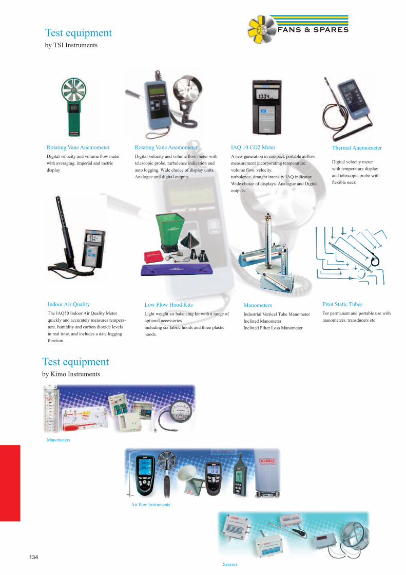
134
Test equipmentby TSI Instruments
Indoor Air QualityThe IAQ50 Indoor Air Quality Meter quickly and accurately measures tempera-ture. humidity and carbon dioxide levels in real time. and includes a data logging function.
Low Flow Hood KitsLight weight air balancing kit with a range of optional accessories including six fabric hoods and three plastic hoods.
Pitot Static TubesFor permanent and portable use with manometers. transducers etc
ManometersIndustrial Vertical Tube ManometerInclined ManometerInclined Filter Loss Manometer
Rotating Vane AnemometerDigital velocity and volume fl ow meter with averaging. imperial and metric display
Rotating Vane AnemometerDigital velocity and volume fl ow meter with telescopic probe. turbulence indication and auto logging. Wide choice of display units. Analogue and digital outputs
IAQ 10 CO2 MeterA new generation in compact. portable airfl ow measurement incorporating temperature. volume fl ow. velocity. turbulence. draught intensity IAQ indicator. Wide choice of displays. Analogue and Digital outputs.
Thermal Anemometer
Digital velocity meter with temperature display and telescopic probe with fl exible neck
Test equipmentby Kimo Instruments
Manometers
Sensors
Air flow Instruments
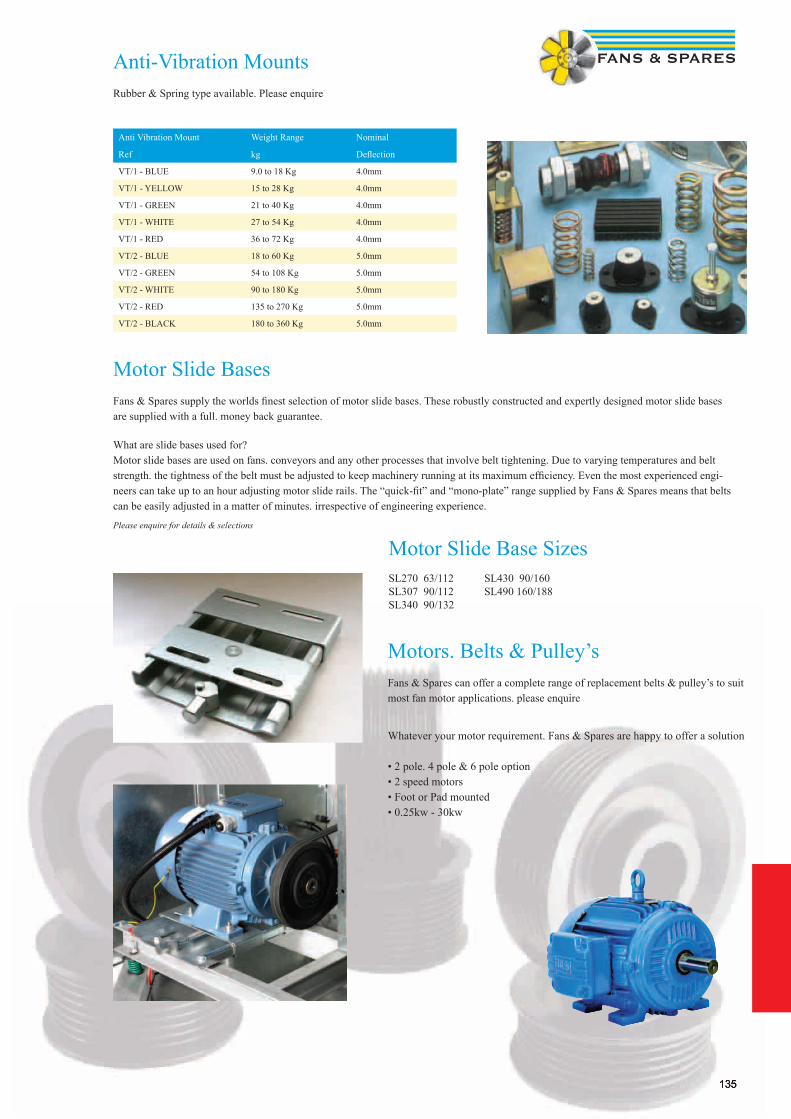
135135
Pitot Static TubesFor permanent and portable use with manometers. transducers etc
Motor Slide Bases
Fans & Spares supply the worlds fi nest selection of motor slide bases. These robustly constructed and expertly designed motor slide bases are supplied with a full. money back guarantee.
What are slide bases used for?Motor slide bases are used on fans. conveyors and any other processes that involve belt tightening. Due to varying temperatures and belt strength. the tightness of the belt must be adjusted to keep machinery running at its maximum effi ciency. Even the most experienced engi-neers can take up to an hour adjusting motor slide rails. The “quick-fi t” and “mono-plate” range supplied by Fans & Spares means that belts can be easily adjusted in a matter of minutes. irrespective of engineering experience.
Please enquire for details & selections
Motors. Belts & Pulley’sFans & Spares can offer a complete range of replacement belts & pulley’s to suit most fan motor applications. please enquire
Whatever your motor requirement. Fans & Spares are happy to offer a solution
• 2 pole. 4 pole & 6 pole option• 2 speed motors• Foot or Pad mounted• 0.25kw - 30kw
Anti-Vibration MountsRubber & Spring type available. Please enquire
Anti Vibration Mount Weight Range Nominal
Ref kg Defl ection
VT/1 - BLUE 9.0 to 18 Kg 4.0mm
VT/1 - YELLOW 15 to 28 Kg 4.0mm
VT/1 - GREEN 21 to 40 Kg 4.0mm
VT/1 - WHITE 27 to 54 Kg 4.0mm
VT/1 - RED 36 to 72 Kg 4.0mm
VT/2 - BLUE 18 to 60 Kg 5.0mm
VT/2 - GREEN 54 to 108 Kg 5.0mm
VT/2 - WHITE 90 to 180 Kg 5.0mm
VT/2 - RED 135 to 270 Kg 5.0mm
VT/2 - BLACK 180 to 360 Kg 5.0mm
Motor Slide Base SizesSL270 63/112 SL430 90/160SL307 90/112 SL490 160/188SL340 90/132
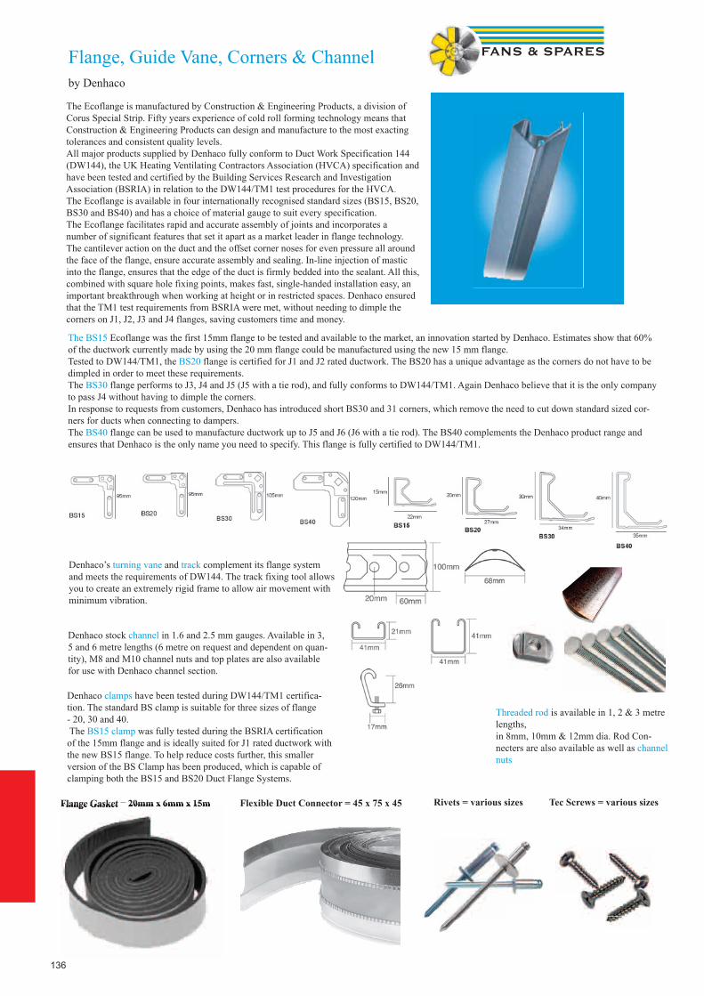
136
Flange, Guide Vane, Corners & Channelby Denhaco
Flange Gasket = 20mm x 6mm x 15m
The Ecoflange is manufactured by Construction & Engineering Products, a division of Corus Special Strip. Fifty years experience of cold roll forming technology means that Construction & Engineering Products can design and manufacture to the most exacting tolerances and consistent quality levels. All major products supplied by Denhaco fully conform to Duct Work Specification 144 (DW144), the UK Heating Ventilating Contractors Association (HVCA) specification and have been tested and certified by the Building Services Research and InvestigationAssociation (BSRIA) in relation to the DW144/TM1 test procedures for the HVCA. The Ecoflange is available in four internationally recognised standard sizes (BS15, BS20, BS30 and BS40) and has a choice of material gauge to suit every specification. The Ecoflange facilitates rapid and accurate assembly of joints and incorporates a number of significant features that set it apart as a market leader in flange technology. The cantilever action on the duct and the offset corner noses for even pressure all around the face of the flange, ensure accurate assembly and sealing. In-line injection of mastic into the flange, ensures that the edge of the duct is firmly bedded into the sealant. All this, combined with square hole fixing points, makes fast, single-handed installation easy, an important breakthrough when working at height or in restricted spaces. Denhaco ensured that the TM1 test requirements from BSRIA were met, without needing to dimple thecorners on J1, J2, J3 and J4 flanges, saving customers time and money.
The BS15 Ecoflange was the first 15mm flange to be tested and available to the market, an innovation started by Denhaco. Estimates show that 60% of the ductwork currently made by using the 20 mm flange could be manufactured using the new 15 mm flange.Tested to DW144/TM1, the BS20 flange is certified for J1 and J2 rated ductwork. The BS20 has a unique advantage as the corners do not have to be dimpled in order to meet these requirements. The BS30 flange performs to J3, J4 and J5 (J5 with a tie rod), and fully conforms to DW144/TM1. Again Denhaco believe that it is the only company to pass J4 without having to dimple the corners. In response to requests from customers, Denhaco has introduced short BS30 and 31 corners, which remove the need to cut down standard sized cor-ners for ducts when connecting to dampers. The BS40 flange can be used to manufacture ductwork up to J5 and J6 (J6 with a tie rod). The BS40 complements the Denhaco product range and ensures that Denhaco is the only name you need to specify. This flange is fully certified to DW144/TM1.
Denhaco’s turning vane and track complement its flange system and meets the requirements of DW144. The track fixing tool allows you to create an extremely rigid frame to allow air movement with minimum vibration.
Denhaco stock channel in 1.6 and 2.5 mm gauges. Available in 3, 5 and 6 metre lengths (6 metre on request and dependent on quan-tity), M8 and M10 channel nuts and top plates are also available for use with Denhaco channel section.
Denhaco clamps have been tested during DW144/TM1 certifica-tion. The standard BS clamp is suitable for three sizes of flange - 20, 30 and 40. The BS15 clamp was fully tested during the BSRIA certification of the 15mm flange and is ideally suited for J1 rated ductwork with the new BS15 flange. To help reduce costs further, this smaller version of the BS Clamp has been produced, which is capable of clamping both the BS15 and BS20 Duct Flange Systems.
Threaded rod is available in 1, 2 & 3 metre lengths,in 8mm, 10mm & 12mm dia. Rod Con-necters are also available as well as channel nuts
Flange Gasket =lange Gasket =lange Gasket 20mm x 6mm x 15m = 20mm x 6mm x 15m = Flexible Duct Connector = 45 x 75 x 45 Rivets = various sizes Tec Screws = various sizes
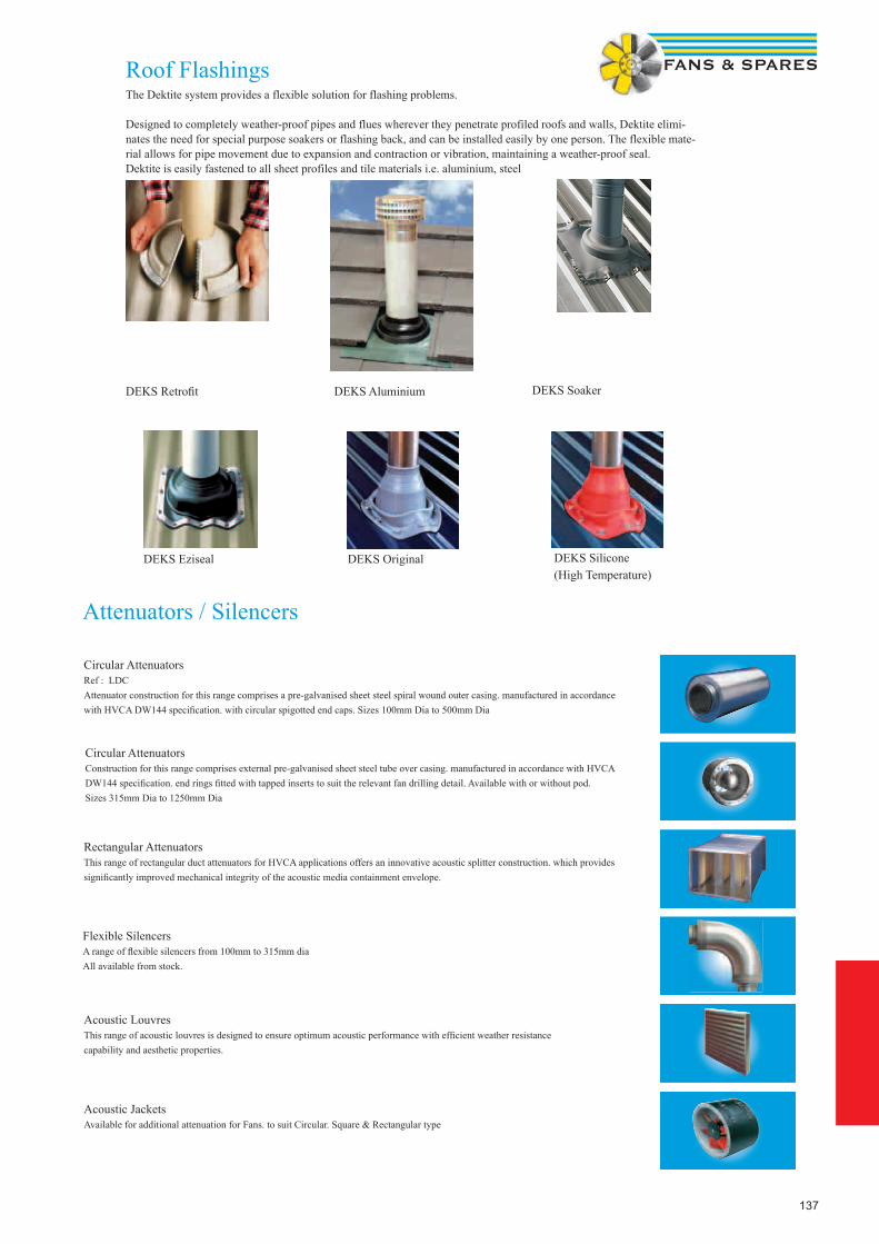
137
Acoustic JacketsAvailable for additional attenuation for Fans. to suit Circular. Square & Rectangular type
Acoustic LouvresThis range of acoustic louvres is designed to ensure optimum acoustic performance with effi cient weather resistance capability and aesthetic properties.
Flexible Silencers A range of fl exible silencers from 100mm to 315mm diaAll available from stock.
Rectangular Attenuators This range of rectangular duct attenuators for HVCA applications offers an innovative acoustic splitter construction. which provides signifi cantly improved mechanical integrity of the acoustic media containment envelope.
Circular Attenuators Construction for this range comprises external pre-galvanised sheet steel tube over casing. manufactured in accordance with HVCA DW144 specifi cation. end rings fi tted with tapped inserts to suit the relevant fan drilling detail. Available with or without pod.Sizes 315mm Dia to 1250mm Dia
Circular Attenuators Ref : LDC Attenuator construction for this range comprises a pre-galvanised sheet steel spiral wound outer casing. manufactured in accordance with HVCA DW144 specifi cation. with circular spigotted end caps. Sizes 100mm Dia to 500mm Dia
Attenuators / Silencers
Roof Flashings
DEKS Retrofi t DEKS Aluminium DEKS Soaker
DEKS Eziseal DEKS Original DEKS Silicone(High Temperature)
The Dektite system provides a flexible solution for flashing problems.
Designed to completely weather-proof pipes and flues wherever they penetrate profiled roofs and walls, Dektite elimi-nates the need for special purpose soakers or flashing back, and can be installed easily by one person. The flexible mate-rial allows for pipe movement due to expansion and contraction or vibration, maintaining a weather-proof seal.Dektite is easily fastened to all sheet profiles and tile materials i.e. aluminium, steel
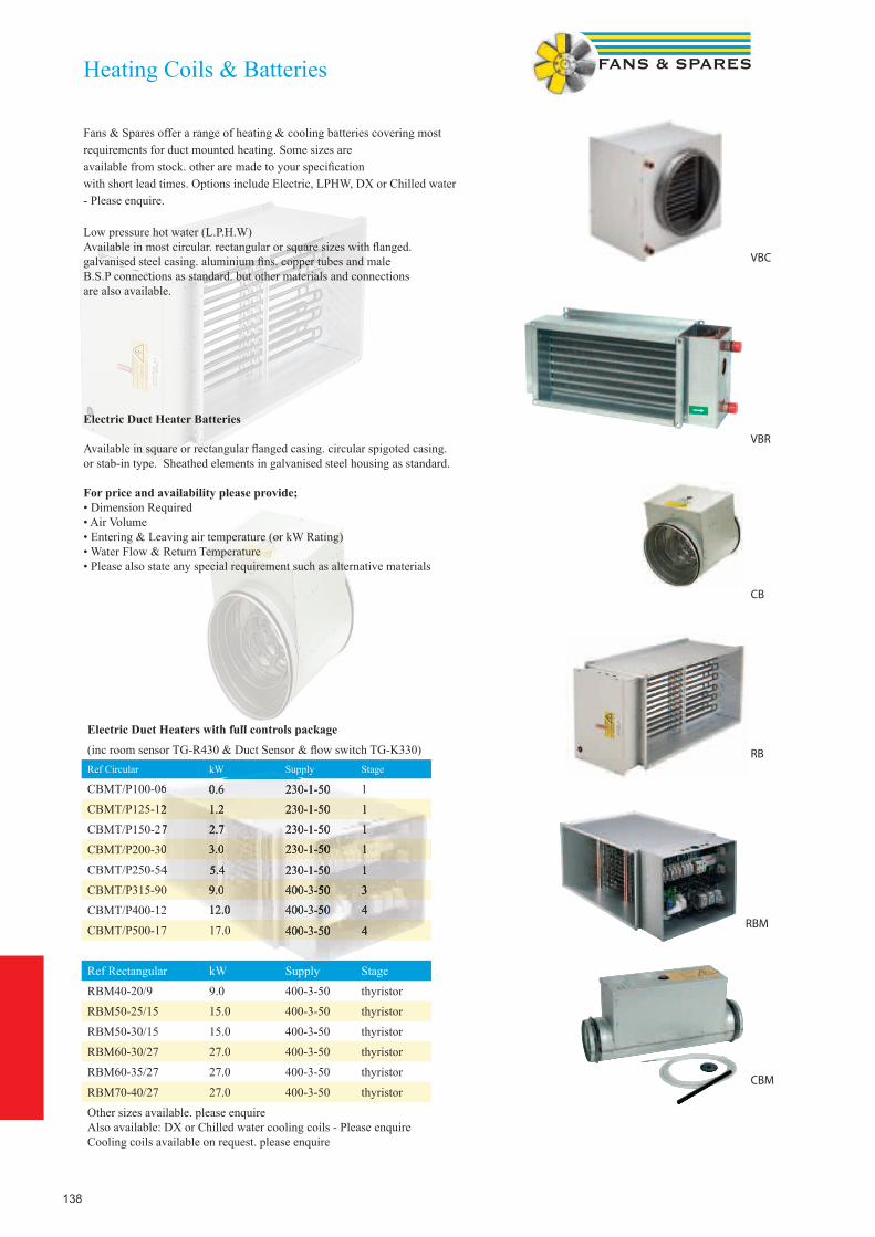
138
Electric Duct Heaters with full controls package(inc room sensor TG-R430 & Duct Sensor & fl ow switch TG-K330)Ref Circular kW Supply Stage
CBMT/P100-06 0.6 230-1-50 1
CBMT/P125-12 1.2 230-1-50 1
CBMT/P150-27 2.7 230-1-50 1
CBMT/P200-30 3.0 230-1-50 1
CBMT/P250-54 5.4 230-1-50 1
CBMT/P315-90 9.0 400-3-50 3
CBMT/P400-12 12.0 400-3-50 4
CBMT/P500-17 17.0 400-3-50 4
Ref Rectangular kW Supply Stage
RBM40-20/9 9.0 400-3-50 thyristor
RBM50-25/15 15.0 400-3-50 thyristor
RBM50-30/15 15.0 400-3-50 thyristor
RBM60-30/27 27.0 400-3-50 thyristor
RBM60-35/27 27.0 400-3-50 thyristor
RBM70-40/27 27.0 400-3-50 thyristor
Other sizes available. please enquireAlso available: DX or Chilled water cooling coils - Please enquireCooling coils available on request. please enquire
Electric Duct Heaters with full controls package
Supply
CBMT/P100-06 0.6 230-1-50
CBMT/P125-12 1.2 230-1-50 1
CBMT/P150-27 2.7 230-1-50 1
CBMT/P200-30 3.0 230-1-50 1
CBMT/P250-54 5.4 230-1-50 1
9.0 400-3-50 3
12.0 400-3-50 4
400-3-50 4
Supply
CBMT/P100-06
Heating Coils & Batteries
Fans & Spares offer a range of heating & cooling batteries covering most requirements for duct mounted heating. Some sizes are available from stock. other are made to your specifi cation with short lead times. Options include Electric, LPHW, DX or Chilled water - Please enquire.
Low pressure hot water (L.P.H.W)Available in most circular. rectangular or square sizes with fl anged.galvanised steel casing. aluminium fi ns. copper tubes and male B.S.P connections as standard. but other materials and connections are also available.
Electric Duct Heater Batteries
Available in square or rectangular fl anged casing. circular spigoted casing. or stab-in type. Sheathed elements in galvanised steel housing as standard.
For price and availability please provide; • Dimension Required• Air Volume • Entering & Leaving air temperature (or kW Rating)• Water Flow & Return Temperature• Please also state any special requirement such as alternative materials
CB
RB
VBR
VBC
RBM
CBM

139
DXRERectangular Duct Mounted DX Cooling Coilby Systemair
• Same model for left-hand or right-hand installation (reversible coil)Stainless steel condensate drip tray. A droplet eliminator can be fi tted regardless of the direction of air fl owEasily removable drip tray to simplify cleaning and inspection
• DXRE are mostly used for central cooling of the ventilation air but can also be used for individual cooling of the air supplied to individual rooms (zones).
• The DXRE is intended for installation in a horizontal duct, with the air fl ow in either direction (reversible coil).
• We recommend that a DE droplet eliminator (accessory) should be installed on the outlet side of the coil if the air velocity is in excess of 2.5 m/s. This prevents water droplets being entrained by the air fl ow out into the duct system
Available in Duct Sizes: 400 x 200 600 x 350500 x 250 700 x 400500 x 300 800 x 500600 x 300 1000 x 500
CWKCircular Duct Mounted WaterCooling Coilby Systemair
• Casing of galvanised sheet steel with copper tubes and aluminium fi ns. Inspection covers for easy cleaning and maintenance.
• Connection sleeves with rubber seal.• Max operating temperature 150 °C• Max operating pressure 1,6 MPa (16Bar)• Available in duct sizes: 100mm, 125mm, 160mm, 200mm, 250mm 315mm & 400mm Dia
PGKRectangular Duct Mounted Water Cooling Coilby Systemair
• Casing of galvanised sheet steel with copper tubes and aluminium fi ns. Inspection covers for easy cleaning and maintenance.
• Cold water-cooling battery for rectangular ducts.
• Casing from galvanised sheet steel. Water-battery from copper tubes and aluminium fi ns. Air vent and drain valve included. Drip pan from stainless steel and condensate connection (R½”). Max working pressure 1.6 MPa (16 bar). For water connection left or right. Two inspection covers for cleaning and maintenance. Droplet separator DE as an accessory regardless of air direction. Recommended for air velocities from 3m/s.
Available in Duct Sizes: 400 x 200 600 x 350500 x 250 700 x 400500 x 300 800 x 500600 x 300 1000 x 500
Cooling Coils, DX & Chilled Water

140
Circular duct accessories
Duct Size Fast Clamps
Back DraughtShutter
PanelFilter Box
BagFilter Box
IrisDamper
SpigotGuard
Circ wallLouvre
MetalQuick Clamp
100 FK100 RSK100 FGR100 FFR100 SPI 100 SG100 IGC100 FSMQC110
125 FK125 RSK125 FGR125 FFR125 SPI 125 SG125 IGC125 FSMQC165
150 FK150 RSK150 FGR150 FFR150 SPI 150 SG150 - FSMQC165
160 FK160 RSK160 FGR160 FFR160 SPI 160 SG160 IGC160 FSMQC165
200 FK200 RSK200 FGR200 FFR200 SPI 200 SG200 IGC200 FSMQC215
250 FK250 RSK250 FGR250 FFR250 SPI 250 SG250 IGC250 FSMQC315
315 FK315 RSK315 FGR315 FFR315 SPI 315 SG315 IGC315 FSMQC315
355 FK355 RSK355 FGR355 FFR355 SPI 355 SG355 - FSMQC525
400 FK400 RSK400 FGR400 FFR400 SPI 400 SG400 - FSMQC525
Duct Size Silencers Water Htr Elec Htr Elec Htr Water Cool
300mm Long 600mm Long 900mm Long 1200mm Long Battery Battery Battery + Battery
100 LDC100-300 LDC100-600 LDC100-900 LDC100-1200 VBC100 CB100 CBMT100 CWK100
125 LDC125-300 LDC125-600 LDC125-900 LDC125-1200 VBC125 CB125 CBMT125 CWK125
150 LDC150-300 LDC150-600 LDC150-900 LDC150-1200 - CB150 CBMT150 -
160 LDC160-300 LDC160-600 LDC160-900 LDC160-1200 VBC160 CB160 CBMT160 CWK160
200 LDC200-300 LDC200-600 LDC200-900 LDC200-1200 VBC200 CB200 CBMT200 CWK200
250 LDC250-300 LDC250-600 LDC250-900 LDC250-1200 VBC250 CB250 CBMT250 CWK250
315 LDC315-300 LDC315-600 LDC315-900 LDC315-1200 VBC315 CB315 CBMT315 CWK315
355 LDC355-300 LDC355-600 LDC355-900 LDC355-1200 - CB355 CBMT355 -
400 LDC400-300 LDC400-600 LDC400-900 LDC400-1200 VBC400 CB400 CBMT400 CWK400
Duct Size Flexible Duct PVC
ALI Acoustic /thermal Semi Rigid CircVCD
CircFire Damper
Circ Intume-scent Fire block
Fusible LinkFire Damper
100 EAPVCFD100 EAALIFD100 EAACOFD100 EASEMFD100 BVCA100 BFCG100 CVT100 EACFD100
125 EAPVCFD125 EAALIFD125 EAACOFD125 EASEMFD125 BVCA125 BFCG125 - EACFD125
150 EAPVCFD150 EAALIFD150 EAACOFD150 EASEMFD150 BVCA150 BFCG150 CVT150 EACFD150
160 EAPVCFD160 EAALIFD160 EAACOFD160 EASEMFD160 BVCA160 BFCG160 -
200 EAPVCFD200 EAALIFD200 EAACOFD200 EASEMFD200 BVCA200 BFCG200 CVT200
250 EAPVCFD250 EAALIFD250 EAACOFD250 EASEMFD250 BVCA250 BFCG250 CVT250
315 EAPVCFD315 EAALIFD315 EAACOFD315 EASEMFD315 BVCA315 BFCG315
355 EAPVCFD355 EAALIFD355 EAACOFD355 BVCA355 BFCG355
400 EAPVCFD400 EAALIFD400 EAACOFD400 BVCA400 BFCG400
External Roof Cowl
Air ValvesDuct Size
Plastic Extract
PlasticSupply
MetalSup/Ext
Fire RatedSup/Ext
StainlessSup/Ext
MountingRing
Wall Grille Kit5-in-1 Size
100 BE100 BS100 EFF100 FSVHD100 FSSSVLF100 RFU100 IGK100 EFS-RCK
125 BE125 BS125 EFF125 FSVHD125 RFU125 IGK125 EFS-RCK
150 BE160 BS160 EFF160 FSVHD150 FSSSVLF150 RFU150 - EFS-RCK
160 BE160 BS160 EFF160 FSVHD160 RFU160 IGK160 EFS-RCK
200 BE200 EFF200 FSVHD200 RFU200 IGK200
Roof Cowl
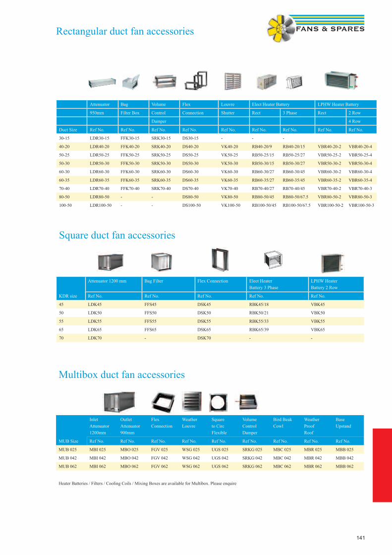
141
Multibox duct fan accessories
MUB Size
InletAttenuator1200mm
OutletAttenuator900mm
Flex Connection
WeatherLouvre
Squareto CircFlexible
VolumeControlDamper
Bird BeakCowl
WeatherProofRoof
BaseUpstand
Ref No. Ref No. Ref No. Ref No. Ref No. Ref No. Ref No. Ref No. Ref No.
MUB 025 MBI 025 MBO 025 FGV 025 WSG 025 UGS 025 SRKG 025 MBC 025 MBR 025 MBB 025
MUB 042 MBI 042 MBO 042 FGV 042 WSG 042 UGS 042 SRKG 042 MBC 042 MBR 042 MBB 042
MUB 062 MBI 062 MBO 062 FGV 062 WSG 062 UGS 062 SRKG 062 MBC 062 MBR 062 MBB 062
Heater Batteries / Filters / Cooling Coils / Mixing Boxes are available for Multibox. Please enquire
Square duct fan accessories
KDR size
Attenuator 1200 mm Bag Filter Flex Connection Elect Heater Battery 3 Phase
LPHW Heater Battery 2 Row
Ref No. Ref No. Ref No. Ref No. Ref No.
45 LDK45 FFS45 DSK45 RBK45/18 VBK45
50 LDK50 FFS50 DSK50 RBK50/21 VBK50
55 LDK55 FFS55 DSK55 RBK55/33 VBK55
65 LDK65 FFS65 DSK65 RBK65/39 VBK65
70 LDK70 - DSK70 - -
Attenuator Bag Volume Flex Louvre Elect Heater Battery LPHW Heater Battery
950mm Filter Box Control Connection Shutter Rect 3 Phase Rect 2 Row
Damper 4 Row
Duct Size Ref No. Ref No. Ref No. Ref No. Ref No. Ref No. Ref No. Ref No. Ref No.
30-15 LDR30-15 FFK30-15 SRK30-15 DS30-15 - - -
40-20 LDR40-20 FFK40-20 SRK40-20 DS40-20 VK40-20 RB40-20/9 RB40-20/15 VBR40-20-2 VBR40-20-4
50-25 LDR50-25 FFK50-25 SRK50-25 DS50-25 VK50-25 RB50-25/15 RB50-25/27 VBR50-25-2 VBR50-25-4
50-30 LDR50-30 FFK50-30 SRK50-30 DS50-30 VK50-30 RB50-30/15 RB50-30/27 VBR50-30-2 VBR50-30-4
60-30 LDR60-30 FFK60-30 SRK60-30 DS60-30 VK60-30 RB60-30/27 RB60-30/45 VBR60-30-2 VBR60-30-4
60-35 LDR60-35 FFK60-35 SRK60-35 DS60-35 VK60-35 RB60-35/27 RB60-35/45 VBR60-35-2 VBR60-35-4
70-40 LDR70-40 FFK70-40 SRK70-40 DS70-40 VK70-40 RB70-40/27 RB70-40/45 VBR70-40-2 VBR70-40-3
80-50 LDR80-50 - - DS80-50 VK80-50 RB80-50/45 RB80-50/67.5 VBR80-50-2 VBR80-50-3
100-50 LDR100-50 - - DS100-50 VK100-50 RB100-50/45 RB100-50/67.5 VBR100-50-2 VBR100-50-3
Rectangular duct fan accessories
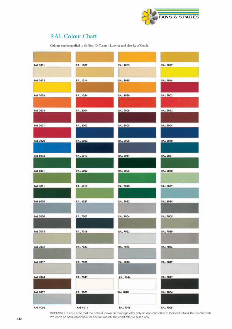
142
RAL Colour ChartColours can be applied to Grilles / Diffusers / Louvres and also Roof Cowls.
DISCLAIMER: Please note that the colours shown on this page offer only an approximation of their actual real-life counterparts. We can’t be held responsible for any mis-match. this chart offers a guide only.
RAL 1001 RAL 1002 RAL 1003 RAL 1012
RAL 1013 RAL 1014 RAL 1015 RAL 1016
RAL 1018 RAL 1024 RAL 1028 RAL 2002
RAL 2003 RAL 2004 RAL 2008 RAL 2012
RAL 3001 RAL 3003 RAL 3005 RAL 3009
RAL 3020 RAL 5002 RAL 5005 RAL 5010
RAL 5012 RAL 5013 RAL 5014 RAL 5021
RAL 6001 RAL 6002 RAL 6005 RAL 6010
RAL 6011 RAL 6017 RAL 6018 RAL 6019
RAL 6020 RAL 6021 RAL 6032 RAL 6034
RAL 7000 RAL 7001 RAL 7004 RAL 7005
RAL 7015 RAL 7016 RAL 7023 RAL 7030
RAL 7032 RAL 7033 RAL 7035 RAL 7036
RAL 7037 RAL 7038 RAL 7040 RAL 7042
RAL 7044 RAL 7045 RAL 7046 RAL 7047
RAL 8017 RAL 9001 RAL 9010 RAL 9004
RAL 9006 RAL 9011 RAL 9016 RAL 9005

143
RAL Colour ChartColours can be applied to Grilles / Diffusers / Louvres and also Roof Cowls.
DISCLAIMER: Please note that the colours shown on this page offer only an approximation of their actual real-life counterparts. We can’t be held responsible for any mis-match. this chart offers a guide only.
Recommended SFP level
2.0 refurbishment and maintenance work
1.5 new installations
Useful Technical DataArea Multiply by
Metres² → Feet² 10.7636
Feet² → Metres² 0.0929
Volume Multiply by
Feet³ → Metres³ 0.0283
Metres³ → Feet³ 35.3134
Flow Rate Multiply by
C.F.M → m³/sec 0.00047
C.F.M → Litres/Sec 0.472
m³/sec → C.F.M 2119
Litres/Sec → C.F.M 2.12
1 m³/s = 1000l/s = 2119 CFM = 3600 m³/h
1000 m³/h =0.278 m³/Sec = 277.8 l/s = 588 CFM
1000 CFM = 0.472 m³/Sec = 472 l/s = 1699m³/h
Pressure Multiply by
Inches W.G → Pascals 249
Inches W.G → Millimetres 25.4
Inches W.G → Kilopascals 0.249
Pascals → Inches W.G 0.004
Millimetres → Inches W.G 0.0393
Velocity Multiply by
Ft/min → m/s 0.0051
m/s → Ft/min 196.85
Formulae
Velocity (m/s) = air flow m³/s
duct area m²
Velocity Pressure Pa = velocity² x 0.6
Heat input kW = m³/s x 1.2 x Δt
∆t (temperature difference -4 to 21ºC) would give a ∆t of 25
Fume Removal (recommended min. velocities across face of extract hood)
Equipment Velocity
Sand Blast Booths (openings) 2.5 m/s
Sand Blast Booths (downwards through booth) 0.4 m/s
Electro-Plating 0.75 - 1. 0 m/s
Electro-Welding 0.5 - 1.0 m/s
Paint Spray Booths (breathing zone) 0.75 m/s
Kitchen Equipment 0.35 - 0.5 m/s
Specific Fan Power
SFP = Total power for Supply & Exhaust Fans (kW)
Air flow m³/s
Mass Multiply by
Tons → Kilograms 1016.05
Tons → Tonnes 1.016
Length Multiply by
Miles → Kilometres 1.609
Yards → Metres 0.914
Feet → Metres 0.305
Inches → Millimetres 25.4
Inches → Centimetres 2.54
Duct diameter Free Area m²
100mm → 0.00785m²
125mm → 0.01227m²
150mm → 0.01767m²
200mm → 0.03142m²
250mm → 0.04909m²
315mm → 0.07794m²
355mm → 0.09898m²
400mm → 0.12566m²
450mm → 0.1590m²
500mm → 0.1964m²
560mm → 0.2463m²
630mm → 0.3118m²
Recommended Air change Rates
Residences. Churches. Storage areas 1-2
Libraries. Banks. Classrooms 2-3
Offices. Assembley Halls. Laboratories 4-6
Hospital Wards. Treatment Rooms. Toilets. Bathrooms. Public Houses
6-8
Cinemas. Theatres. Garages 6-10
Cafes. Canteens. Dance Halls 8-12
Restaurants. Domestic kitchens. Laundries 10-15
Commercial Kitchens. Bakeries. Boiler Houses. Swimming Pools
15-30
Paint Shops. Foundries. Furnace Rooms 30-60
General ventilation rates per person
8 litres per person
144
1. InterpretationIn these conditions:1.1 the following expressions shall have the mean-ings set opposite them unless the context otherwise requires: “Acknowledgement of Order” the written acknowledgement given by the Seller to the Buyer in response to an Order; “the Buyer” the person. firm or company with whom the Contract is made; “the Contract” the contract between the Seller and the Buyer for the sale of the Goods into which these conditions are incorporated; “Goods” the goods (including any instalment of the goods or any parts of them) which the Seller is to supply in accordance with these conditions; “Order” the written or oral order placed by the Buyer; “Quotation” the written or oral quotation given by the Seller to the Buyer or to others on the Buyer’s behalf; “the Seller” the company referred to overleaf as the Seller; “writing” and “written” shall include telex and facsimile transmission;1.2 any reference in these conditions to any provision of a statute shall be construed as a reference to that provision as amended. re-enacted or extended at the relevant time;1.3 any reference to the singular includes the plural and reference to a gender includes every gender;1.4 the headings are inserted for convenience only and shall not affect the interpretation of these conditions.2. Formation of Contract2.1 All Quotations and Acknowledgements of Order given by the Seller shall be deemed to include these conditions except (subject to the provisions of clause 2.6) insofar as they are inconsistent with any special terms or conditions contained in the Quotation or the Acknowledgement of Order (as the case may be).2.2 The Quotation does not form an offer capable of acceptance by the Buyer but merely an invitation to the Buyer to make an offer in accordance with its terms.2.3 No Order shall be deemed to be accepted by the Seller unless and until acknowledged and confirmed in writing by the Seller’s authorised representative.2.4 Any terms or conditions contained in the Order or any other document delivered or sent by the Buyer which are inconsistent with these conditions shall not form part of the Contract unless (subject to the provisions of clause 2.6) accepted by the Seller in writing in the Acknowledgement of Order2.5 If subsequent to any contract between the Seller and the Buyer into which these conditions are incor-porated any contract for the supply of goods similar to the Goods is made between the Seller and the Buyer whether the same is in writing. orally or otherwise. with-out express reference to any conditions. such contract shall be deemed to be subject to these conditions.2.6 No variation to these conditions shall be effective unless agreed in writing between the authorised representatives of the Buyer and the Seller.3. Basis of the Sale3.1 The Seller’s employees or agents are not authorised to make any representations concerning the Goods unless confirmed by the Seller in writing. In entering into the Contract the Buyer acknowledges that it does not rely on any such representations which are not so confirmed and that it shall not have any right of action against the Seller arising out of or in connection with any such representation except in the case of fraud.3.2 Any advice or recommendation given by the Seller or its employees or agents to the Buyer or its employees or agents as to the storage. Application or use of the Goods which is not confirmed in writing by the Seller is followed or acted upon entirely at the Buyer’s own risk and accordingly the Seller shall not be liable for any such advice or recommendation which is not so confirmed.3.3 In entering into this Contract the Buyer assumes responsibility for the Goods being sufficient for its purpose. As the Seller is not responsible for system design and as the Buyer has greater knowledge of his own requirements the Seller shall not accept any responsibility for the performance or suitability of the Goods in their final operating environment whether or not details of the final
operating environment have been made available to the Seller.3.4 Any typographical. clerical or other error or omission in any sales literature. Quotation. price list. Acknowl-edgement of Order. invoice or other document or information issued by the Seller shall be subject to cor-rection without any liability on the part of the Seller.3.5 The Buyer shall be responsible to the Seller for ensuring the accuracy of the terms of any Order (including any applicable specification) and for giving the Seller any necessary information relating to the Goods within a sufficient time to enable the Seller to perform the Contract in accordance with its terms.3.6 If the Goods are to be manufactured or any process is to be applied to the Goods by the Seller in accordance with a specification submitted by the Buyer. the Buyer shall indemnify the Seller against all loss. damages. costs and expenses awarded against or incurred by the Seller in settlement of any claim for infringement of any patent. copyright. design. trade mark or other industrial or intellectual property rights of any other person which results from the Seller’s use of the Buyer’s specification.3.7 The Seller reserves the right at any time to change the design. construction and/or specification of the Goods if such change is required to conform with any applicable statutory or EC requirements or if such change will not in the opinion of the Seller at the time that such change is made adversely affect the quality or performance of such Goods.3.8 No order which has been accepted by the Seller may be cancelled by the Buyer except with the agreement in writing of the Seller and on terms that the Buyer shall indemnify the Seller in full against all loss (including loss of profit). costs (including the cost of all labour and ma-terials used). damages. charges and expenses incurred by the Seller as a result of cancellation.4. Delivery4.1 Delivery of the Goods shall be made by the Buyer collecting the Goods at the Seller’s premises at any time after the Seller has notified the Buyer that the Goods are ready for collection or. if some other place for delivery is agreed by the Seller. by the Seller delivering the Goods to that place.4.2 Any dates quoted for the delivery of the Goods are ap-proximate only and the Seller shall not be liable for any delay in delivery of the Goods howsoever caused. Time for delivery shall not be of the essence of the Contract unless previously agreed by the Seller in writing.4.3 The Seller may make delivery by instalments. Where Goods are to be delivered in instalments each delivery shall constitute a separate contract and failure by the Seller to deliver any one or more of the instalments in accordance with these conditions or any claim by the Buyer in respect of any one or more instalments shall not entitle the Buyer to treat the Contract as a whole as repudiated.4.4 If the Buyer fails to take delivery of the Goods or fails to give the Seller adequate delivery instructions at the time stated for delivery. then without prejudice to any other right or remedy available to the Seller. the Seller may:4.4.1 store the Goods until actual delivery and charge the Buyer for the reasonable costs (including insurance) of storage; or4.4.2 sell the Goods at the best price readily obtainable and (after deducting all reasonable storage and selling expenses) charge the Buyer for any shortfall below the price under the Contract.4.5 No claim for damage to any Goods or for any short-ages in the Goods delivered will be considered by the Seller unless it is advised of such claim in writing within 7 days of the date of delivery of the Goods or such part thereof as are actually delivered. In the absence of such advice. the Buyer will be deemed to have accepted the Goods. No claim for non delivery will be considered by the Seller unless it is advised in writing within 14 days of the date of the Seller’s invoice. Any claim for damage. shortages or non delivery shall also be notified by the Buyer to the carrier (if any) in the manner and within the appropriate time limit prescribed by the carrier’s terms
and conditions. as advised by the Seller to the Buyer. In the event of a failure by the Buyer to give the appropri-ate notices then any claim which the Buyer may other-wise have pursuant to this condition will be deemed to have been waived and will be absolutely barred.5. Guarantee5.1 The Seller will endeavour to transfer to the Buyer the benefit of any warranty or guarantee given by the manufacturer of the Goods to the Seller.5.2 The Seller will free of charge within a period of 3 months from the date of delivery or such longer period as may be referred to in the Seller’s sales literature repair or at its option replace any Goods which are proved to the reasonable satisfaction of the Seller to be defective in design. materials or workmanship unless. in the Seller’s reasonable opinion:5.2.1 the Goods have been altered in any way whatsoever or repaired without the Seller’s approval or have been subjected to wilful damage negligence abnormal working conditions or misuse; or5.2.2 the Goods have been improperly installed or connected; or5.2.3 the Buyer has failed to observe any operational or mainte-nance requirements relating to the Goods; or5.2.4 the Buyer has failed to notify the Seller in writing of any defect or suspected defect within 14 days of the same coming to the knowledge of the Buyer; or.5.2.5 the Buyer is in breach of this or any other contract made with the Seller; or5.2.6 the defect in the Goods arises from any drawing. design or specification supplied or approved by or on behalf of the Buyer. Notwithstanding the provisions of this condition. the Seller shall not be obliged to repair or replace any defective Goods unless and until the Buyer returns such Goods to the Seller (without any charge or cost to the Seller) if reasonably requested by the Seller so to do. In the case of any defective Goods which it would be unreasonable for the Seller to require the Buyer to return to the Seller (e.g. because of their size or because following installation or connection they form an integral part of a larger system or structure which it would be unreasonable to require the Buyer to dismantle) notwithstanding the provisions of this condi-tion. the Seller shall not be obliged to repair or replace such Goods unless the Seller is easily able to obtain access to the same for repair or replacement. Any Goods replaced by the Seller will belong to the Seller. Any repaired or replacement Goods will be guaranteed on these terms for the unexpired portion of the 3 month or longer guarantee period.6. Seller’s Liability6.1 Save as provided in conditions 5.1 and 5.2 and sub-ject to condition 6.2 the Seller will be under no liability under the Contract. in tort or otherwise for any personal injury. death. loss or damage of any kind whatsoever whether direct or indirect and whether consequential or otherwise (including but not limited to loss of profits. loss of business or contracts. loss of operating time or loss of use whether foreseeable or not) resulting from any defect in the Goods or from any work done in connection therewith or as a result thereof and the Seller hereby excludes all conditions. warranties and stipulations express or implied. statutory. customary or otherwise to the fullest extent permitted by law which but for such exclusion would or might subsist in favour of the Buyer.6.2 The Seller. does not exclude liability for:6.2.1 any breach of the implied condition that the Seller has or will have the right to sell the Goods when property therein is to pass;6.2.2 when the Buyer deals as a consumer (as defined in section 12 of the Unfair Contract Terms Act 1977). any breach of the implied terms relating to the conformity of the goods with their description or sample. as to their quality or fitness for a particular purpose;6.2.3 death or personal injury resulting from its negligence or that
Terms & Conditions of Sale

145
of its employees;6.2.4 direct physical damage to or physical loss of the property of the Buyer resulting from the Seller’s. its employee’s or agents’ negligent acts or omissions and which arise out of the performance of its obligations under the Contract provided that:6.2.4.1 the Seller shall only accept liability for any such damage or loss if and to the extent that such liability is covered by the public/product liability policy taken out by the Seller and operative at the time of the damage or loss. Details of such insurance policy will be made available to the Buyer upon request. If the Buyer requests in writing additional insurance the Seller will take all rea-sonable steps to obtain it on the Buyers behalf and any premium or additional premium and any other expenses incurred in obtain-ing such insurance shall be payable by the Buyer to the Seller.6.2.4.2 the Seller’s liability under this condition 6.2.4 shall not exceed £1 million in aggregate in respect of any one event or series of events.7. Risk7.1 Risk of damage to or loss of the Goods shall pass to the Buyer:7.1.1 in the case of Goods to be delivered at the Sellers premises. at the time when the Seller notifies the Buyer that the Goods are available for collection; or7.1.2 in the case of Goods to be delivered otherwise than at the Seller’s premises. at the time of delivery or. if the Buyer wrongfully fails to take delivery of the Goods. the time when the Seller has tendered delivery of the Goods.8. Property in the Goods8.1 Notwithstanding delivery and the passing of risk in the Goods the property in the Goods shall not pass to the Buyer until:8.1.1 the price of the Goods has been paid in full; and8.1.2 payment has been made to the Seller of all sums due or owing from the Buyer to the Seller on any account whatsoever.8.2 Until such time as property in the Goods passes to the Buyer in accordance with condition 8.1:8.2.1 the Buyer shall hold the Goods as the Seller’s fiduciary agent and bailee. shall not obliterate any identifying mark on the Goods or their packaging and shall keep the Goods separate from any other goods of the Buyer or third parties properly stored. protected and insured and identified as the Seller’s property; and8.2.2 the Buyer shall be entitled to use or (subject to condition 8.3) sell the Goods in the ordinary course of to its business.8.3 The Buyer shall not be entitled to pledge or in any way charge by way of security for any indebtedness any of the Goods which remain the property of the Seller but if the Buyer does so all monies owing by the Buyer to the Seller shall (without prejudice to any other right or remedy of the Seller) forthwith become due and payable.8.4 Where the Seller is unable to determine whether any goods are the Goods the Buyer shall be deemed to have sold all goods of the kind sold by the Seller to the Buyer in the order in which they were invoiced to the Buyer.8.5 The Seller may at any time after payment for the Goods has become due take possession of the Goods (which for the avoidance of doubt shall include the right to stop the Goods in transit) and remove them and the Buyer shall be deemed to have granted irrevocable authority to the Seller to enter upon the Buyer’s prem-ises or other premises where the Goods may be and. by the Seller’s employees or agents. take possession of the Goods and (if necessary) dismantle the Goods from anything to which they are attached.8.6 The Seller shall have the right to maintain an action against the Buyer for the price of the Goods notwithstanding that property in the Goods has not passed.8.7 Nothing in the Contract shall constitute the Buyer the agent of the Seller in respect of any re-sale of the Goods by the Buyer so as to confer upon a third party any rights against the Seller9. Price9.1 Except as otherwise stated in any Quotation and un-less otherwise agreed in writing between the Buyer and the Seller all prices quoted are the price of the Goods
(excluding VAT) ex-works and where the Seller agrees to deliver the Goods otherwise than at the Seller’s prem-ises the Buyer shall be liable to pay the Seller’s charges for transport. packaging and insurance.9.2 The Seller reserves the right. by giving notice to the Buyer at any time before delivery. to increase the price of the Goods to reflect any increase in the cost to the Seller which is due to any factor beyond the control of the Seller (such as. without limitation. any foreign exchange fluctuation. currency regulation. alteration of duties. significant increase in the costs of labour. materials or other costs of manufacture). any change in delivery dates. quantities or specifications for the Goods which is requested by the Buyer or any delay caused by any instructions of the Buyer or failure of the Buyer to give the Seller adequate information or instructions.9.3 The cost of pallets and returnable containers will be charged to the Buyer in addition to the price of the Goods but full credit will be given to the Buyer provided they are returned undamaged to the Seller before the due payment date.10. Payment10.1 Where no account has been opened in advance by the Seller in respect of the Buyer. the Seller will not be obliged to deliver the Goods until the Buyer has paid the amount shown on the pro-forma invoice relating to the Goods.10.2 Where an account has been opened for the Buyer. the Seller may in its absolute discretion set and on 3 days prior written notice to the Buyer alter the Buyer’s credit limit and the Seller reserves the right not to de-liver the Goods if the price thereof increases the amount owed by the Buyer to the Seller beyond the Buyer’s credit limit from time to time.10.3 Where an account has been opened for the Buyer and the price of the Goods together with all other indebtedness of the Buyer to the Seller does not exceed the Buyer’s credit limit from time to time. the price of the Goods will be paid by the Buyer within 30 days from the end of the month in which the Seller’s invoice is issued or within such other period as the Buyer and the Seller may agree in writing. The time of payment shall be of the essence of the Contract.10.4 If the Buyer fails to make any payment on the due date then. without prejudice to any other right or remedy available to the Seller. the Seller may without liability;10.4.1 suspend any further deliveries to the Buyer or cancel the Contract or any other contract between the Seller and the Buyer;10.4.2 charge the Buyer interest (both before and after any judge-ment) on the amount unpaid at the rate of 5% per annum above the base rate from time to time of Barclays Bank Plc until payment in full is made; and10.4.3 appropriate any payment made by the Buyer to such of the Goods (or the goods supplied under any other contract between the Buyer. and the Seller) as the Seller may in its absolute discretion think fit (notwith-standing any purported appropriation by the Buyer).10.5 The Seller shall be entitled to payment for all instalments of Goods delivered to the Buyer notwithstanding that the remainder of the Goods shall not have been delivered.10.6 The Buyer shall not be entitled to withhold payment of any amount payable under the Contract because of any disputed claim of the Buyer. in respect of faulty goods or any other alleged breach of contract whether in respect of the Contract or any other contract between the Buyer and the Seller not shall the Buyer be entitled to set off against any amount payable under the Contract to the Seller any monies owed by the Seller to the Buyer on any account whatsoever. whether such a right is conferred on the Buyer by statute or otherwise.11. Force MajeureThe Seller shall not be liable to the Buyer or be deemed to be in breach of the Contract by reason of any delay in performing or any failure to perform any of the Seller’s obligations in relation to the Goods if the delay or
failure is due to any cause beyond the Seller’s reason-able control. Without prejudice to the generality of the foregoing. the following shall be regarded as causes beyond the Seller’s reasonable control: act of God. explosion. lighting. flood. tempest. fire or accident; war or threat of war. sabotage. insurrection. civil disturbance or requisition; acts. restrictions. regulations. by-laws. prohibitions. or measures of any kind on the part of any governmental. parliamentary or local authority; import or export regulations or embargoes; strikes. lockouts or other industrial actions or trade disputes (whether involving employees of the Seller or any third party); dif-ficulties in obtaining raw materials. labour. fuel. parts or machinery; power failure or breakdown in machinery.12. Cancellation and Suspension of the Contract12.1 This condition applies if:12.1.1 the Buyer is in breach of any of its obligations under the Contract or any other contract between the Buyer and the Seller; or12.1.2 unforeseen events including (without prejudice to the gen-erality of the foregoing) those referred to in condition 11 materially affect the commercial effect of the Contract; or12.1.3 the Buyer makes any voluntary arrangement with its credi-tors or (being an individual or firm) becomes bankrupt or (being a company) becomes subject to an administration order or goes into liquidation (otherwise than for the purposes of amalgamation or reconstruction); or12.1.4 an encumbrancer takes possession. or a receiver is appointed. of any of the property or assets of the Buyer; or12.1.5 the Buyer ceases or threatens to cease to carry on business; or12.1.6 the Seller reasonably apprehends that any of the events mentioned in conditions 12.1.3. 12.1.4 or 12.1.5 is about to occur in relation to the Buyer and notifies the Buyer accordingly; or12.1.7 the Seller receives notice of any claim alleging that the Goods or any part thereof or any process applied to the Goods infringe any patent. copyright. design right. trademark or other industrial or intellectual property rights of any other person.12.2 If this condition 12 applies then. without prejudice to any other right or remedy available to the Seller. the Seller shall be entitled to cancel the Contract or suspend any further deliveries under the Contract by notice to the Buyer without any liability to the Buyer and if the Goods have been delivered but not paid for then the price shall become immediately due and payable not-withstanding any previous agreement or arrangement to the contrary.13. Export Terms13.1 In these conditions “Incoterms” means the international rules for the interpretation of trade terms of the International Chamber of Commerce as in force at the date when the Contract is made. Unless the context otherwise requires. any term or expression which is defined in or given a particular meaning by the provisions of Incoterms shall have the same meaning in these conditions. but if there is any conflict between the provisions of Incoterms and these conditions. the latter shall prevail.13.2 Where the Goods are supplied for export from the United Kingdom. the provisions of this condition 13 shall (subject to any special terms agreed in writing between the Buyer and the Seller) apply notwithstand-ing any other provision of these conditions13.3 The Buyer shall be responsible for complying with any legislation or regulations governing the importation of the Goods into the country of destination and for the payment of any duties on them.13.4 Unless otherwise agreed in writing between the Buyer and the Seller. the Goods shall be delivered fob the air or sea port of shipment and the Seller shall be under no obligation to give notice under section 32(3) of the Sale of Goods Act 1979.
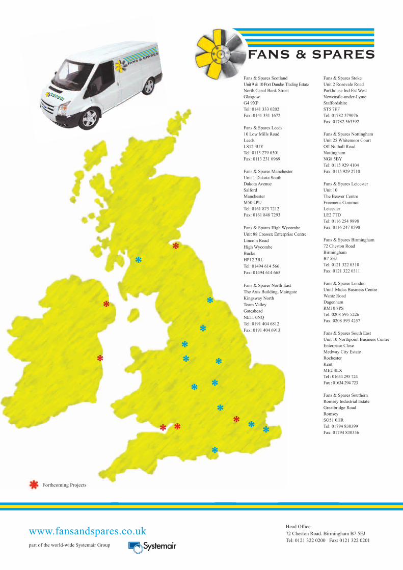
Fans & Spares Scotland Unit 9 & 10 Port Dundas Trading EstateNorth Canal Bank StreetGlasgowG4 9XPTel: 0141 333 0202Fax: 0141 331 1672
Fans & Spares Leeds10 Low Mills RoadLeedsLS12 4UYTel: 0113 279 0501Fax: 0113 231 0969
Fans & Spares ManchesterUnit 1 Dakota SouthDakota AvenueSalfordManchesterM50 2PUTel: 0161 873 7212Fax: 0161 848 7293
Fans & Spares High WycombeUnit 88 Cressex Enterprise CentreLincoln RoadHigh WycombeBucksHP12 3RLTel: 01494 614 566Fax: 01494 614 665
Fans & Spares North EastThe Axis Building, MaingateKingsway NorthTeam ValleyGatesheadNE11 0NQTel: 0191 404 6812Fax: 0191 404 6913
Fans & Spares StokeUnit 2 Rosevale RoadParkhouse Ind Est WestNewcastle-under-LymeStaffordshireST5 7EFTel: 01782 579076Fax: 01782 563592
Fans & Spares NottinghamUnit 25 Whitemoor CourtOff Nuthall RoadNottinghamNG8 5BYTel: 0115 929 4104Fax: 0115 929 2710
Fans & Spares LeicesterUnit 10The Beaver CentreFreemens CommonLeicesterLE2 7TDTel: 0116 254 9898Fax: 0116 247 0590
Fans & Spares Birmingham72 Cheston RoadBirminghamB7 5EJTel: 0121 322 0310Fax: 0121 322 0311
Fans & Spares LondonUnit1 Midas Business CentreWantz RoadDagenhamRM10 8PSTel: 0208 595 5226Fax: 0208 593 4257
Fans & Spares South EastUnit 10 Northpoint Business CentreEnterprise CloseMedway City EstateRochesterKentME2 4LXTel : 01634 295 724Fax : 01634 294 723
Fans & Spares SouthernRomsey Industrial EstateGreatbridge RoadRomseySO51 0HRTel: 01794 830399Fax: 01794 830336
www.fansandspares.co.uk Head Offi ce72 Cheston Road. Birmingham B7 5EJTel: 0121 322 0200 Fax: 0121 322 0201
part of the world-wide Systemair Group
Forthcoming Projects
*
*
*
** *
**
**
***
**
* **