fan coil unit · air cooled water chiller floor standing cabinet (dx/cw) universal type split ac...
TRANSCRIPT

Fan Coil UnitChilled Water / Direct Expansion
Universal Type
Duct Type Unit
Special Exposed
Decorative and Innovative
Ceiling Suspended
Floor Standing
Provides Turnkey Projects
t o C o m m i s s i o n i n g o f P r o j e c t sH V A C R
Conceptual PlanningConceptual Planning

Equipment is manufactured on latestCNC machines with prompt deliveries
Clients are welcome to visit our facilities &to discuss technical details
Provides Turnkey Projects, Starting fromconceptual planning till the commissioningof HVACR projects
Heat Load Calculation
HVAC System Concept & Design
Supply of HVAC Equipment
Installation
Testing & Commissioning
Operation & Maintenance
Package Mobile AC Plant
Package Type Unit
Floor Standing Split AC
Double Skinned AHU Concealed Type AHU
Vertical Type AHUAir Cooled Water Chiller Floor Standing Cabinet (DX/CW)
Cassette Type Split ACUniversal Type Split AC
Tube Size 3/8”OD, 1/2”OC, 5/8”ODAir Handling Units Duct Type Split AC UnitCold Rooms & Reefer Containers
COOL POINT (Pvt.) Ltd. Introduces new phenomenon of Water Cooled Air Conditioning Systemin small capacity units (1-Ton, 1.5-Ton, 2-Ton and 2.5-Ton
THE LARGEST MANUFACTURER OF AIR CONDITIONING EQUIPMENT

Fan Coil Unit
Contents
Legend
IntroductionLegendNomenclatureGeneral FeaturesComponent FeaturesOptionsApplication FlexibilityPhysical DataNominal Capacity Ratings & Correction FactorsElectric HeatersElectrical DataMotor Technical DataSound Power LevelsNoise CriteriaWater Pressure DropAir DeliverySelection ProcedureValves & ControlsDX Connection SizesMachine WeightsDimensional DataGuide Specifications
The following legends are used throughout this manual:
AFR Air Flow RateBEP Baked Enamel PaintCfm Cubic feet per minutedB DecibelsEADB EnteringAir Dry BulbEAWB EnteringAir Wet BulbET Evaporating TemperatureEWT Entering Water TemperatureESP External Static PressureFt Total Capacity FactorFtwg Feet fo Water GaugeFs Sensible Capacity FactorGPM Gallons per minuteHz Hertzinwg Inch of Water GaugekW Kilowattskg KilogramskPa Kilo PascalsLADB LeavingAir Dry BulbLAWB LeavingAir Wet Bulblbs Pounds weight (British units)l/s Liters per secondMBh 1000 BtuhNC Noise CriteriaOD Outside DiameterPh PhasePa PascalsSC Sensible CapacitySCCF Sensible Capacity Correction FactorSPL Sound Pressure LevelTC Total CapacityTCCF Total Capacity Correction FactorTR Tons of refrigeration = 12 MBHUSgpm US Gallons per minuteV VoltsWFR Water Flow RateWTR Water Temperature RiseWPD Water Pressure Drop
General Features
COOL POINT fan coil units have been designed with therequirement of the Pakistani market foremost inconsideration.
Fan coil units are ideally suited for installation in chilled wateror DX applications to meet air conditioning requirements ofindividual rooms throughout the year. Increasingly, architectsrequire a hidden indoor unit with custom enclosure to matchthe aesthetic requirements of the space. The cooling mediumcan be refrigerant for DX applications in :
small residences
apartment houses
small commercial establishments
mosques
For individual room temperature control inchilled water applications, Hi - Static fan coils can be an idealsolution on major projects involving :
Apartment Complexes
Office Blocks
Hospitals & Clinics
Shopping Malls & Centers
Airports
Hi-rise Buildings
Hotels & Motels
Commercial Developments
Schools & Colleges
Libraries
••••
••••••••••
1

Fan coil units provide flexibility of architectural design,economy of operation and space usage, individual roomcontrol with privacy, quietness, versatility of location andinstallation, and multiplicity of control system. All thesereasons make the fan coils the first choice as Fan Coil unitsfrom COOLPOINT are: Built in the Gulf...for the world.
High efficiency coil with high efficiency wavy
corrugated fins.
Hi-efficiency, low power consumption PSC electric
motor.
Hi-efficiency forward curved fan for quiet
operation.
Manual air vent.
Heavy gauge galvanised casing & fan housing. Hot
dip is standard.
Insulated heavy gauge drain pan.
Isolating grommet for additional vibration isolation.
Quick electrical connections.
Cooling & heating coils are manufactured from 3/8" (9.5mm)OD seamless copper tubes mechanically bonded to highefficiency wavy corrugated aluminium fins. Copper fins areavailable as an option.
Coils are factory leak tested by air pressure at 300 psig (2068kPa) under water. Air vent is standard. Chilled water coolingcoils are available in 3, 4 and 6 rows. Heating coils areavailable in 1, 2, 3, 4 & 6 rows. DX coils are available in 3, 4 &6 rows. Coil connections are plain tube extensions suppliedLH or RH as required for chilled water and DX units.
Distributor for DX type fan coils is provided as standard withcorrect sizes and quantity of outlet pipes. Coils are rated inaccordance with ARI - 410/2001. fan coil units can besupplied with a maximum total of 6 rows/coil as follows :
Cooling and heating with 4 and 2 pipe system
combination upto a total of 6 rows only.
Maximum 6 row cooling coil and electric heater
battery.
Maximum 6 row DX cooling coil and electric heater
battery.
Features:
•
•
•
••
•••
•
•
•
Component Features
Coils
Fan / Motor
Hi - Static fan coil units use centrifugal double inlet doublewidth low noise fans direct driven by single phase, 3-speedpermanent split capacitor motor. These motors have integralthermal protection, low temperature rise, are highly efficient,have high power factor and operate almost noiselessly withpermanent lubricated sleeve bearings.
Fan/Blower Selection Software
2
Fan Coil Unit

Casing
Drain Pan
Options
Units are constructed from high gauge galvanised steel sheetcomplying with ASTM-A525 and JSIG-3302 for maximumprotection against corrosion. On request, as option,electrostatic polyster powder coating on zinc coatedgalvanized and phosphatised sheets are available. Othercolors available as a further option, on request, at additionalcharge.
Fabricated from heavy gauge zinc coated steel sheets, paintedirrespective of the type of finish for unit casing and insulatedfrom outside by 4 mm thick polyethylene foam insulation formaximum protection against sweating and corrosion. Drainpan is extended to include coil, headers and U - bends. Drainconnection 3/4" (19mm) O.D. is provided for removal ofcondensation.
The standard options available for Hi - Static Fan Coil Unitsinclude:
(specify optionAAV)
(specify option FEH) :
For heating during cooler months.Available for DX or chilledwater on all Hi - Static fan coil unit models. Order shouldspecify FEH1 for Variant 1 and FEH2 for Variant 2.Thermostat must be ordered separately.
(wall mounted decorative type)
Cooling only or Cooling/Heating thermostats available withsub-bases. Details on pages 20 - 22.
(specify option DSU)
Recommended for all units installed in locations having ahigh temperature difference between supply air temperatureand surrounding environment of the Hi - Static fan coil units.
AutomaticAir Vent
Electric Heater Battery
Thermostats
Double Skin Units
This option is available for DDP models only. Additionalsound attenuation is achieved with double skinning. Coldbridges are avoided fully in the sandwich construction.
Various options on valve packages and control systems areavailable. 8 different valve packages are available factoryinstalled or loose for field mounting along with 3 options oncontrol packages. Full details of options available see fullwrite-up on pages 20 - 22.
Available for models DDC and DDP only to provide extendedand additional protection against condensation below valvepackages.
1. Auxiliary drip lip. supplied loose to be fitted on theedge of the drain pan under the valves. SpecifyoptionADP.
2. Double skin drain pan with heavy gauge galvanisedsteel internal & external skin. The inner and outerskins are filled with fibre glass insulation. Internalskin additionally protected with painted finish.Specify option PDI.
3. Stainless steel drain pan insulated from outside with4mm thick polyethylene foam insulation. Specifyoption PSD.
4. Double skin drain pan with stainless steel internalskin and heavy gauge galvanized steel outer skinsandwiched between a fibre glass insulation.Specify option PSID.
(specify option BEP)
Available for models DDF only where required for exposedinstallation. Model DDE comes standard with this option.Colors available ivory white (RAL 7032) or light grey (RAL8019). Specify with option code BEP. Optionally other RALcolors may be available. Specify color with code BEP.
Controls
Auxillary and / or Double Insulated Drain Pans
Powder Coated Decorative Finish
Options available:
Variant 1 Variant 2
6 1 x 1.0 2 x 1.0
8 1 x 1.5 2 x 1.5
10 1 x 1.0+1 x 1.5 3 x 1.5
12 1 x 3.0 2 x 3.0
15 1 x 3.0 2 x 3.0
18 1 x 4.0 2 x 4.0
21 1 x 4.0 2 x 4.0
24 1 x 4.0 2 x 4.0
Unit Size
Number of heater element
3
Fan Coil Unit

Supply and ReturnAir Grille
Discharge Plenum
Powder coated discharge grille and/or return grille availablefor DDE & DDF. Double deflection discharge grille availableunder option code GDD. Single deflection discharge or returngrille available under option code RAG.
Grills are powder coated to match color of unit, if option BEPordered or in standard aluminium finish if option BEP notrequired or ordered.
(Specify option GDP)
A discharge plenum for free standing DDF models only isavailable. Option BEP must be ordered with this option.Option GDP includes, in addition, a double deflection supplygrille and a single deflection return air grille, powder coated inmatching color. Colors available ivory white (RAL 7032) orlight grey (RAL8019). Specify with option code.
Hi - Static fan coil units are available in a capacity range of600 - 2400 cfm (283-1133 l/s), in various models having 8sizes each. Configurations available include ceilingsuspended horizontal or vertical floor mounted.
Ceiling suspended, concealed application with DX or chilledwater coils.
Ceiling suspended for concealed applications, includes afactory installed plenum. The plenum is lined with 1/2" glassfibre insulation. Units are supplied with 1" cleanable filter asstandard.
Ceiling suspended, exposed type includes basic DDC, plus acabinet with removable access panels lined with 1/2" fibreglass insulation. Units are supplied with 1" cleanable filter.Units are with electrostatically applied polyster powder coatand can be supplied with supply and return air grilles onrequest.
Floor mounted, vertical supply with 1" cleanable filter. Unitscan be supplied with supply and return grill on request withelectrostatic polyster powder coat, oven-baked. Units have aremovable access panel to provide complete access to coil andmotor blower section. All units can be supplied for either freeor ducted air delivery.
Application Flexibility
1. T1
2. T2
3. T3
4. T4
4
Fan Coil Unit

Notes
Chilledwatercapacity ratingsarebasedonnominalair flowrate;airentering temperatureDB/WB80/67oF(26.5/19.4oC),45oF(7.2oC)enteringchilled
water temperature and 10oF (5.5oC) water temperature rise.
NominalCapacityRatings(forFCUofAllTypes)
Total
Capacity
Sensible
Capcaity
Water
Flow
Rate
Water
Pressure
Drop
Total
Capacity
Sensible
Capcaity
Water
Flow
Rate
Water
Pressure
Drop
Total
Capacity
Sensible
Capcaity
Water
Flow
Rate
Water
Pressure
Drop
cfm MBh MBh Usgpm ftwg MBh MBh USGpm ftwg MBh MBh USGpm ftwg
l/s kW kW l/s kPa kW kW l/s kPa kW kW l/s kPa
600 12.8 10.1 2.6 0.9 17.5 12.6 3.5 1.9 23.8 15.9 4.8 4.2
283 3.8 3.0 0.2 2.8 5.1 3.7 0.2 5.7 7.0 4.7 0.3 12.7
800 18.0 13.6 3.6 1.8 23.3 16.6 4.7 3.4 31.6 21.1 6.3 7.6
378 5.3 4.0 0.2 5.5 6.8 4.9 0.3 10.3 9.2 6.2 0.4 22.8
1000 23.2 17.4 4.6 1.7 29.9 21.2 6.0 3.2 40.3 26.8 8.1 7.1
472 6.8 5.1 0.3 5.2 8.8 6.2 0.4 9.6 11.8 7.9 0.5 21.1
1200 30.0 21.5 6.0 5.5 38.0 26.1 7.6 9.9 44.9 30.7 9.0 3.2
566 8.8 6.3 0.4 16.3 11.1 7.6 0.5 29.5 13.1 9.0 0.6 9.5
1500 37.5 26.6 7.5 8.7 41.0 30.0 8.2 2.3 56.5 38.4 11.3 5.2
708 11.0 7.8 0.5 26.1 12.0 8.8 0.5 6.9 16.6 11.2 0.7 15.5
1800 47.4 33.2 9.5 7.9 51.5 37.2 10.3 2.1 70.4 47.3 14.1 4.6
849 13.9 9.7 0.6 23.7 15.1 10.9 0.7 6.2 20.6 13.9 0.9 13.7
2100 51.5 37.3 10.3 3.7 61.5 43.9 12.3 3.0 83.3 55.6 16.7 6.6
991 15.1 10.9 0.6 11.1 18.0 12.9 0.8 9.1 24.4 16.3 1.1 19.7
2400 60.0 42.9 12.0 5.2 72.1 50.7 14.4 4.3 96.4 64.0 19.3 9.1
1133 17.6 12.6 0.8 15.5 21.1 14.9 0.9 12.7 28.3 18.8 1.2 27.2
6 Rows
06
08
10
Size
3 Rows 4 RowsNominal
Airflow
Rate
24
12
15
18
21
PhysicalData
06 08 10 12 15 18 21 24
cfm 600 800 1000 1200 1500 1800 2100 2400
l/s 283 378 472 566 708 849 991 1133
Type -
inch 12 12 16 12 12 16 16 16
mm 305 305 406 305 305 406 406 406
inch 20 24 24 36 42 42 48 54
mm 508 610 610 914 1067 1067 1219 1372
ft² 1.7 2.0 2.7 3.0 3.5 4.7 5.3 6.0
m² 0.15 0.19 0.25 0.28 0.33 0.43 0.50 0.56
Type -
Code - 7-7 7-7 9-7 7-7 7-7 9-7 9-7 9-7
Quantity # 1 1 1 2 2 2 2 2
Type -
Size Watts 147 147 147 147 147 147 245 245
Quantity # 1 1 1 2 2 2 2 2
Total Power Input Watts 346 346 396 692 692 792 1100 1100
Copper tubes mechanically bonded to Hi-Efficiency w avy corrugated Aluminium Fins
Double Inlet Double Width Centrifugal Forw ard Curve Direct Drive
220-240V/1Ph/50-60Hz, 3 Speed Electric Motor w ith Permanent Split Capacitor
Fin Height
Fin Length
Face Area
Coil
Fan
Motor
Unit Size
Nominal Airflow Rate
5
Fan Coil Unit

NominalCapacityRatings(forAllTypeofFCU)
Notes:
1. Direct expansion capacity ratings based on nominal air flow rate, air entering temperature, 80/67 oF (26.5/19.4oC) DB/WB, 40oF (4.4oC)
evaporating temperature.
2. For different entering air conditions and/or evaporating temperature, use correction factors as in Charts 2 & 3.
Direct Expansion Coil
Total CapacitySensible
CapacityTotal Capacity
Sensible
CapacityTotal Capacity
Sensible
Capacity
cfm MBh MBh MBh MBh MBh MBh
l/s kW kW kW kW kW kW
600 21.2 13.2 24.9 15.5 29.3 18.2
283 6.2 3.9 7.3 4.5 8.6 5.3
800 26.7 16.8 31.8 19.9 37.8 23.7
378 7.8 4.9 9.3 5.8 11.1 6.9
1000 34.6 21.6 40.8 25.4 48.2 30.1
472 10.1 6.3 12.0 7.5 14.1 8.8
1200 40.1 25.2 47.7 29.9 56.7 35.5
566 11.8 7.4 14.0 8.8 16.6 10.4
1500 48.3 30.6 57.9 36.4 69.4 43.6
708 14.2 9.0 17.0 10.7 20.3 12.8
1800 61.3 38.4 72.7 45.3 86.1 53.7
849 18.0 11.3 21.3 13.3 25.2 15.7
2100 70.8 44.4 84.1 52.5 99.8 62.3
991 20.8 13.0 24.6 15.4 29.2 18.3
2400 80.2 50.4 95.5 59.7 113.4 71.0
1133 23.5 14.8 28.0 17.5 33.3 20.8
6 Rows
06
08
10
Size
3 Rows 4 RowsNominal
Airflow Rate
24
12
15
18
21
Notes
Table7databasedonNominalAirFlow,70 oF (21.1oC)entering air temperature,180/160oF (82.2/71.1oC)entering/leavinghotwater temperature.
For other conditions refer to correction factor Chart 4.
Air temp. rise = Capacity (Btuh)
[oF] 1.1 x cfm
or Capacity (kW)
[oC] 1.232 x l/s
NominalCapacityRating(ForallTypesofFCU) HotWater Coils
Total
Capacity
Water Flow
Rate
Water
Pressure
Drop
Total
Capacity
Water Flow
Rate
Water
Pressure
Drop
Total
Capacity
Water Flow
Rate
Water
Pressure
Drop
cfm MBh USGpm ftwg MBh USGpm ftwg MBh USGpm ftwg
l/s kW l/s kPa kW l/s kPa kW l/s kPa
600 16.5 1.7 1.1 33.3 3.3 5.5 44.4 4.4 11.3
283 4.8 0.1 3.4 9.8 0.2 16.4 13.0 0.3 33.8
800 22.1 2.2 2.0 43.3 4.3 9.4 53.6 5.4 3.4
378 6.5 0.1 6.1 12.7 0.3 28.1 15.7 0.3 10.1
1000 28.6 2.9 1.9 55.6 5.6 8.8 68.6 6.9 3.1
472 8.4 0.2 5.8 16.3 0.4 26.2 20.1 0.4 9.4
1200 36.7 3.7 5.9 62.2 6.2 4.3 84.9 8.5 9.0
566 10.8 0.2 17.6 18.2 0.4 12.8 24.9 0.5 26.9
1500 38.5 3.8 1.4 77.3 7.7 6.7 100.3 10.0 5.1
708 11.3 0.2 4.3 22.7 0.5 20.1 29.4 0.6 15.2
1800 48.9 4.9 1.3 97.5 9.8 6.1 125.2 12.5 4.5
849 14.3 0.3 3.9 28.6 0.6 18.1 36.7 0.8 13.5
2100 58.5 5.8 1.9 114.4 11.4 8.5 147.8 14.8 6.4
991 17.1 0.4 5.7 33.5 0.7 25.4 43.3 0.9 19.1
2400 68.7 6.9 2.7 132.0 13.2 11.6 169.8 17.0 8.6
1133 20.1 0.4 7.9 38.7 0.8 34.5 49.8 1.1 25.8
3 Rows
06
08
10
Size
Nominal
Airflow Rate
1 Row 2 Rows
24
12
15
18
21
6
Fan Coil Unit
Electric Heaters
Application
Capacity
Contactors and Controls
Heater Elements
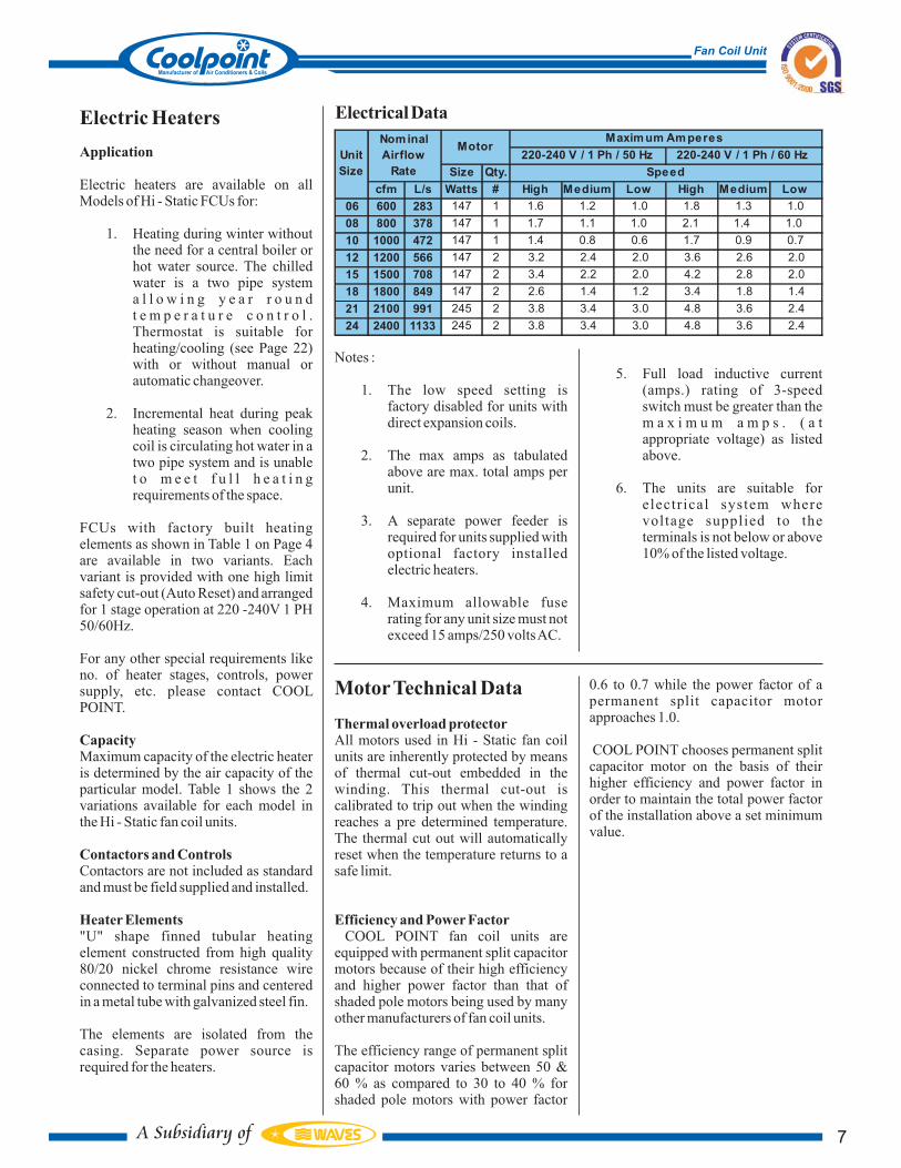
Electric heaters are available on allModels of Hi - Static FCUs for:
1. Heating during winter withoutthe need for a central boiler orhot water source. The chilledwater is a two pipe systema l l o w i n g y e a r r o u n dt e m p e r a t u r e c o n t r o l .Thermostat is suitable forheating/cooling (see Page 22)with or without manual orautomatic changeover.
2. Incremental heat during peakheating season when coolingcoil is circulating hot water in atwo pipe system and is unablet o m e e t f u l l h e a t i n grequirements of the space.
FCUs with factory built heatingelements as shown in Table 1 on Page 4are available in two variants. Eachvariant is provided with one high limitsafety cut-out (Auto Reset) and arrangedfor 1 stage operation at 220 -240V 1 PH50/60Hz.
For any other special requirements likeno. of heater stages, controls, powersupply, etc. please contact COOLPOINT.
Maximum capacity of the electric heateris determined by the air capacity of theparticular model. Table 1 shows the 2variations available for each model inthe Hi - Static fan coil units.
Contactors are not included as standardand must be field supplied and installed.
"U" shape finned tubular heatingelement constructed from high quality80/20 nickel chrome resistance wireconnected to terminal pins and centeredin a metal tube with galvanized steel fin.
The elements are isolated from thecasing. Separate power source isrequired for the heaters.
Notes :
1. The low speed setting isfactory disabled for units withdirect expansion coils.
2. The max amps as tabulatedabove are max. total amps perunit.
3. A separate power feeder isrequired for units supplied withoptional factory installedelectric heaters.
4. Maximum allowable fuserating for any unit size must notexceed 15 amps/250 voltsAC.
5. Full load inductive current(amps.) rating of 3-speedswitch must be greater than them a x i m u m a m p s . ( a tappropriate voltage) as listedabove.
6. The units are suitable forelectrical system wherevoltage supplied to theterminals is not below or above10% of the listed voltage.
MotorTechnical Data
Thermal overload protector
Efficiency and Power Factor
All motors used in Hi - Static fan coilunits are inherently protected by meansof thermal cut-out embedded in thewinding. This thermal cut-out iscalibrated to trip out when the windingreaches a pre determined temperature.The thermal cut out will automaticallyreset when the temperature returns to asafe limit.
COOL POINT fan coil units areequipped with permanent split capacitormotors because of their high efficiencyand higher power factor than that ofshaded pole motors being used by manyother manufacturers of fan coil units.
The efficiency range of permanent splitcapacitor motors varies between 50 &60 % as compared to 30 to 40 % forshaded pole motors with power factor
0.6 to 0.7 while the power factor of apermanent split capacitor motorapproaches 1.0.
COOL POINT chooses permanent splitcapacitor motor on the basis of theirhigher efficiency and power factor inorder to maintain the total power factorof the installation above a set minimumvalue.
ElectricalData
Size Qty.
cfm L/s Watts # High Medium Low High Medium Low
06 600 283 147 1 1.6 1.2 1.0 1.8 1.3 1.0
08 800 378 147 1 1.7 1.1 1.0 2.1 1.4 1.0
10 1000 472 147 1 1.4 0.8 0.6 1.7 0.9 0.7
12 1200 566 147 2 3.2 2.4 2.0 3.6 2.6 2.0
15 1500 708 147 2 3.4 2.2 2.0 4.2 2.8 2.0
18 1800 849 147 2 2.6 1.4 1.2 3.4 1.8 1.4
21 2100 991 245 2 3.8 3.4 3.0 4.8 3.6 2.4
24 2400 1133 245 2 3.8 3.4 3.0 4.8 3.6 2.4
Unit
Size
Maxim um Am peresNominal
Airflow
Rate
Motor
Speed
220-240 V / 1 Ph / 50 Hz 220-240 V / 1 Ph / 60 Hz
7
Fan Coil Unit
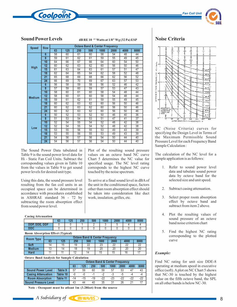
The Sound Power Data tabulated inTable 9 is the sound power level data forHi - Static Fan Coil Units. Subtract thecorresponding values given in Table 10from the values in Table 9 to get soundpower levels for desired unit type.
Using this data, the sound pressure levelresulting from the fan coil units in anoccupied space can be determined inaccordance with procedures establishedin ASHRAE standard 36 - 72 bysubtracting the room absorption effectfrom sound power level.
Plot of the resulting sound pressurevalues on an octave band NC curveChart 5 determines the NC value forspecified usage. The NC level ratingcorresponds to the highest NC curvetouched by the noise spectrum.
To arrive at a final sound level in dBA ofthe unit in the conditioned space, factorsother than room absorption effect shouldbe taken into consideration like ductwork, insulation, grilles, etc.
NC (Noise Criteria) curves forspecifying the Design Level in Terms ofthe Maximum Permissible SoundPressure Level for each Frequency BandSample Calculation :
The calculation of the NC level for asample application is as follows:
1. Refer to sound power leveldata and tabulate sound powerdata by octave band for theselected size and unit speed.
2. Subtract casing attenuation.
3. Select proper room absorptioneffect by octave band andsubtract from item 2 above.
4. Plot the resulting values ofsound pressure of an octaveband noise criterion chart
5. Find the highest NC ratingcorresponding to the plottedcurve
Find NC rating for unit size DDE-8operating at medium speed in executiveoffice (soft).Aplot on NC Chart 5 showsthat NC-30 is touched by the highestvalue on the fifth octave band, the SPLon all other bands is below NC-30.
Example:
Noise CriteriaSoundPowerLevels
63 125 250 500 1000 2000 4000 8000
6 58 60 61 60 58 54 48 44
8 59 61 62 61 59 55 49 45
10 64 66 67 66 64 60 54 50
12 60 62 63 62 60 56 50 46
15 61 63 64 63 61 57 51 47
18 62 64 65 64 62 58 52 48
21 65 68 69 68 66 62 56 52
24 66 69 70 69 67 63 57 53
6 56 58 59 58 56 52 46 42
8 57 59 60 59 57 53 47 43
10 58 60 61 60 58 54 48 44
12 58 60 61 60 58 54 48 44
15 59 61 62 61 59 55 49 45
18 60 62 63 62 60 56 50 46
21 60 62 63 62 60 56 50 46
24 60 62 63 62 60 56 50 46
6 50 52 53 52 50 46 40 36
8 51 53 54 53 51 47 41 37
10 52 54 55 54 52 48 42 38
12 52 54 55 54 52 48 42 38
15 53 55 56 55 53 49 43 39
18 53 55 56 55 53 49 43 39
21 54 56 57 56 54 50 44 40
24 54 56 57 56 54 50 44 40
Low
SizeOctave Band & Center Frequency
Speed
High
Medium
dB RE 10 -12 Watts at 1/8" Wg (32 Pa) ESP
63 125 250 500 1000 2000 4000 8000
Soft 14 15 19 22 23 22 22 22
Medium 13 14 18 19 20 20 20 20
Hard 11 11 12 14 15 15 16 17
Room Absorption Effect (Typical)
Octave Band & Center FrequencyRoom Type
63 125 250 500 1000 2000 4000 8000
DDP, DDE, DDF 0 0 1 2 3 5 4 4
DDC 0 0 0 0 0 0 0 0
Casing Attenuation
63 125 250 500 1000 2000 4000 8000
Sound Power Level Table 9 57 59 60 59 57 53 47 43
Casing Attenuation Table 10 -0 -0 -1 -2 -3 -5 -4 -4
Room Absorption Table 11 -14 -15 -19 -22 -23 -22 -22 -22
Sound Pressure Level 43 44 40 35 31 26 21 17
Octave Band Analysis for Sample Calculation
Octave Band & Center Frequency
Note : Occupant must be atleast 1m (3.28feet) from the source
8
Fan Coil Unit
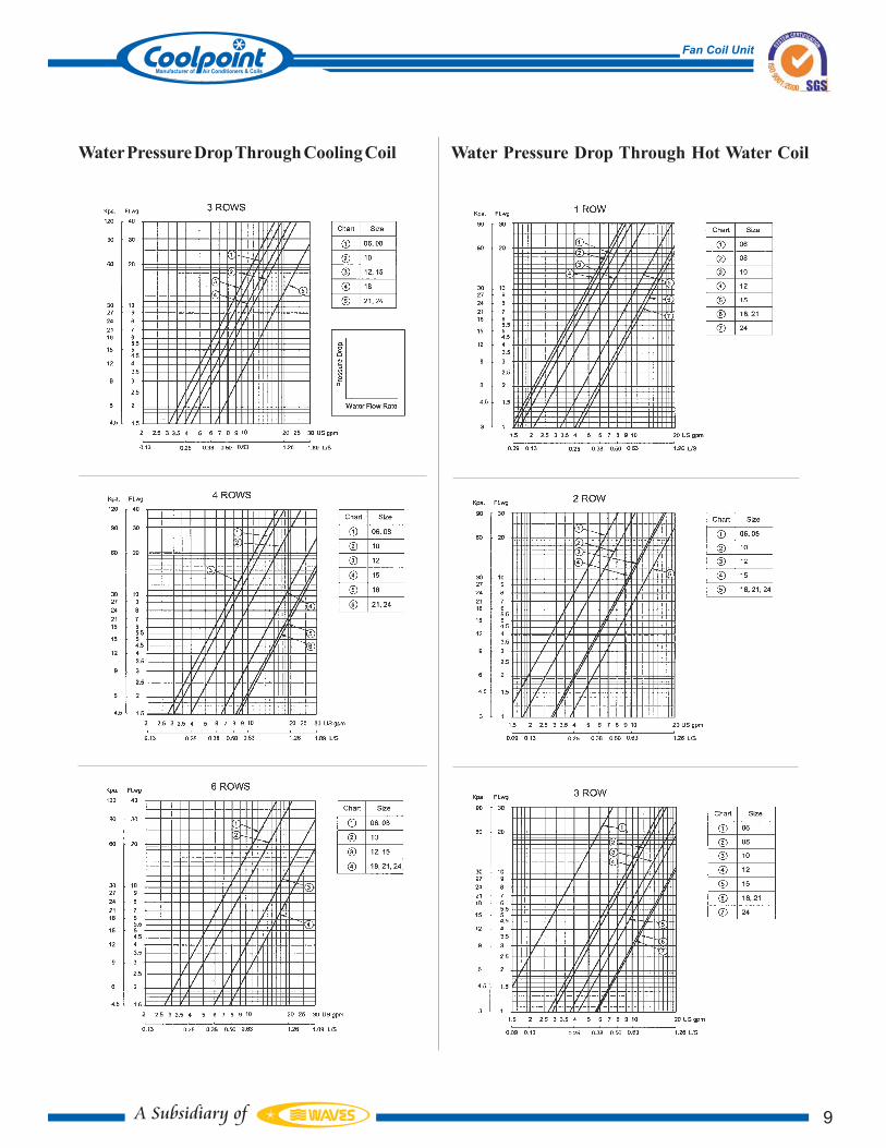
Water Pressure Drop Through Hot Water CoilWaterPressureDropThroughCoolingCoil
9
Fan Coil Unit

Air Delivery (50 Hz)
inw g 0.1 0.2 0.3 0.4 0.1 0.2 0.3 0.4 0.1 0.2 0.3 0.4
Pa 25 50 75 100 25 50 75 100 25 50 75 100
cfm 666 648 629 604 658 640 619 592 642 624 599 567
l/s 314 306 297 285 310 302 292 279 303 294 283 267
cfm 829 803 781 756 817 793 771 744 795 774 749 717
l/s 391 379 369 357 385 374 364 351 375 365 354 339
cfm 1019 970 901 816 1002 946 875 791 961 899 826 745
l/s 481 458 425 385 473 447 413 373 454 424 390 352
cfm 1301 1269 1231 1181 1285 1251 1210 1155 1252 1213 1163 1099
l/s 614 599 581 558 606 590 571 545 591 572 549 519
cfm 1588 1553 1513 1464 1568 1532 1490 1436 1529 1489 1438 1373
l/s 749 733 714 691 740 723 703 677 722 703 679 648
cfm 1959 1836 1687 1517 1904 1776 1628 1463 1796 1667 1523 1367
l/s 924 867 796 716 898 838 768 690 847 787 719 645
cfm 2408 2230 2027 1801 2317 2139 1941 1725 2152 1981 1796 1598
l/s 1136 1052 956 850 1093 1009 916 814 1016 935 848 754
cfm 2540 2376 2175 1944 2466 2295 2094 1870 2320 2146 1954 1742
l/s 1199 1121 1026 917 1164 1083 988 882 1095 1013 922 822
cfm 483 467 448 419 479 463 442 412 471 454 431 397
l/s 228 220 211 198 226 218 209 194 222 214 203 188
cfm 657 641 623 597 652 636 616 589 642 625 602 571
l/s 310 303 294 282 308 300 291 278 303 295 284 269
cfm 691 703 689 650 696 702 683 640 702 697 668 620
l/s 326 332 325 307 328 331 322 302 331 329 315 293
cfm 963 931 891 832 953 921 878 814 934 899 849 778
l/s 454 439 421 392 450 434 414 384 441 424 401 367
cfm 1304 1273 1236 1184 1292 1260 1219 1163 1268 1231 1183 1118
l/s 615 601 583 559 610 595 575 549 598 581 558 527
cfm 1401 1398 1344 1249 1406 1388 1324 1223 1402 1359 1280 1173
l/s 661 660 634 589 663 655 625 577 662 641 604 553
cfm 2177 2066 1908 1716 2133 2005 1843 1654 2028 1887 1726 1546
l/s 1027 975 900 810 1006 946 870 781 957 891 815 730
cfm 2222 2150 2015 1830 2202 2108 1961 1773 2137 2013 1855 1669
l/s 1048 1015 951 864 1039 995 925 837 1008 950 875 788
cfm 380 362 332 296 378 358 327 292 373 349 319 283
l/s 179 171 157 140 178 169 155 138 176 165 150 134
cfm 503 481 457 429 499 477 452 424 490 468 443 415
l/s 237 227 216 203 235 225 214 200 231 221 209 196
cfm 454 459 464 432 453 460 463 427 452 463 459 415
l/s 214 216 219 204 214 217 218 201 213 219 216 196
cfm 757 718 655 580 752 707 644 570 737 687 623 551
l/s 357 339 309 274 355 334 304 269 348 324 294 260
cfm 1001 957 906 849 990 946 895 837 969 924 872 814
l/s 472 451 428 401 467 446 422 395 457 436 412 384
cfm 905 925 919 835 905 928 912 821 909 931 895 793
l/s 427 437 434 394 427 438 431 387 429 439 422 374
cfm 1853 1828 1758 1649 1849 1809 1727 1612 1825 1760 1662 1539
l/s 874 862 830 778 872 854 815 761 861 830 785 726
cfm 1851 1848 1803 1711 1853 1840 1782 1682 1850 1813 1735 1622
l/s 873 872 851 808 874 868 841 794 873 856 819 765
Low
06
08
10
12
15
18
21
24
24
Medium
06
08
10
12
15
18
21
24
6 Rows
External Static Pressure
High
06
08
10
12
15
18
21
Speed FCU
3 Rows 4 Row s
Size 06 08 10 12 15 18 21 24
c f m 600 800 1000 1200 1500 1800 2100 2400
L/s 283 378 472 566 708 849 991 1133
Nom
AFR
10
Fan Coil Unit
also space limitations, psychrometricfeasibility, circulation and ventilation,room acoustical effect, control system,piping accesses including overall chilledwater circuits and effect of diversity onsame.
1. Select unit that deliversapproximate ly a i r f lowrequired at desired speed andexternal static pressure fromair flow rate tables. Select unitwith air flow equal or morethan that required.
2. Apply correction factors toselected unit and find out theactual total and sensiblecooling capacity.
3. Repeat step 1 if requiredparameter is not met withactual values obtained frominitially selected unit.
Selection Procedure
•
•
Control sys tem desi red
especially if winter heating isrequired.
Economy of layout
Once a particular model or models in theHi -Static series is selected afterconsideration of the above factors, it isnecessary to select the unit and coil sizeto match. It is possible to obtain differentunit size with or without different coildepths to meet given design parameters.
The correct unit with correct coil size isobtained only when required cfm atdefined speed; i.e. High, Medium orLow to meet sensible load of the space ismatched to the correct coil providing therequired sensible cooling or outlettemperature at given flow rate anddesign temperature rise with the unitoperating at functional sound levels.Toachieve this the engineer or designermust not only check aesthetic needs but
Selection
Selection Considerations
In selecting Hi - Static Fan Coil units fora specific application the factors to beconsidered should include:
Available space for the unit
including floor to ceilingheight
Presence of high sensible or
peripheral loads in space
Functionality of intended
space usage.
Availability of access for pipes,
drains & power.
Compatibility with intended
space finish.
Fresh air and ventilation
requirements
Noise level desired at peak or
part load operations
•
•
•
•
•
•
•
Selection for Specified Total Cooling Capacity
Specified Performance
Example 1
Air flow 680 cfm,0.2inwg ESP, medium speedTotal capacity 18.8 MBh,Sensible Capacity 14.4 MBhEntering air temp. deg. F 86/69 DB/WBEntering water temp. deg. F 44Power supply 220V/1PH/50Hz
Unit to be installed concealed for a small shop. Unit required with plenum andsuitable for ducted return connection.
1. From Table 13, unit model FCU - DDC - 10/3R gives 703 cfm at0.2inwg and medium speed.
2. The air flow correction factor from Table 5 on page 9 using actualair flow/nom.air flow = 703/1000 = 70.3%Ft = 0.78 Fs = 0.76
3. Find nominal capacity for selected unit at 80/67 oF DB/WB EWT= 45 oF and 10 oF WTR from Table 3 and applying correctionfactor obtained from Step 2.Total capacity = 23.2 MBh x 0.78 = 18.1 MBhSensible capacity = 17.4 MBh x 0.76 = 13.2 MBh
4. Find TCCF by dividing specified capacity by total capacity inStep 3; 18.8/18.1 = 1.04
5. Enter chart 1 on Page 7 at TCCF = 1.04 and draw a horizontal lineuntil the intersection with entering air wet bulb temperature andthen draw a vertical line. From the point of intersection withentering water temperature read WTR = 13°F and from the pointof intersection with entering air dry bulb temperature read SCCF= 1.18.
6. Multiply sensible cooling capacity in Step 3 by SCCF (step 5)13.2 x 1.18 = 15.6 MBh
7. Find water flow rate (GPM)GPM =
0.5 x WTR=
0.5 x 13.0
Actual total cooling capacity (MBh)
18.8 .
= 2.89 USgpm
Refer to water pressure drop and read water pressure drop through coil = 1.5ft. wg.
Using Tables 9 & 10 with Chart 5 find NC is the highest value in the octaveband.
Air flow 543 l/s, 75Pa ESP, high speedSensible Capacity 7 kWEntering air temp. deg. C 25.56 / 17.22 DB/WBEntering water temp. deg. C 6.11 °CPower supply 220V/1PH/50Hz
Unit to be installed concealed for a small shop. Unit required with plenum andsuitable for ducted return connection.
1. From air delivery Table 14 select model size DDP-12/4R givingair flow 556 l/s at 75Pa ESP.
2. The air flow correction factor = 556/566 = 98% using Table 5 onpage 9.Ft = 0.99 Fs = 0.99
3. Find nominal capacity for model size 12/4R from Table 3 andapply correction factor obtained from Step 2.Total capacity = 11.14 x 0.99 = 11.03 kWSensible capacity = 7.65 x 0.99 = 7.57 kW
4. Find SCCF by dividing the specified sensible capacity bysensible capacity in Step 3; 7/7.57 = 0.93
5. Enter Chart 1 at SCCF = 0.93 and draw a horizontal line and fromthe point of intersection with entering air dry bulb temperature,draw a vertical line. From the point of intersection with enteringwater temperature read WTR = 6.7°C. The point of intersectionwith entering air wet bulb read TCCF = 0.72.
6. Find the actual total cooling capacity0.72 x 11.03 = 7.94 kW
7. Calculate the actual water flow rate WFR(l/s) = 7.94 x 0.239 / 6.7= 0.283 from the water pressure drop Chart at 0.283 l/s read waterpressure drop 12 kPa.
Selection for Specified Sensible Capacity
Specified Performance
Example 2 (SI System)
11
Fan Coil Unit

Unit Capacity Rating at Specified WaterTemperature Rise
Specified Performance
Selection Procedure for Chilled Water Coil
Example 3
Example 4
Unit Model DDP10/6R 0.2inwg ESPhigh speedEntering air temp. deg. F 88/71 DB/WBEntering water temp. deg. F 8Water temperature rise deg. F 8Power Supply 220V / 1Ph / 50Hz
1. From air flow rate Table 14 specified model gives 866 cfm866/1000 = 86.6% air flow correction factor. (Table 5)Ft = 0.92 Fs = 0.91
2. Enter the chart at specified WTR and draw a horizontal line.3. From the point of intersection with entering water temp. draw a
vertical line till the intersection with entering air wet bulb tempreads TCCF = 1.23 and from the point of intersection with airentering dry bulb read SCCF = 1.26
4. Apply factors from Step 1 and Step 3 and multiply by nominaltotal and sensible cooling capacities.Actual total capacity = 40.3 x 0.92 x 1.23 = 45.6 MBhActual sensible capacity = 26.8 x 0.91 x 1.26 = 30.7 MBh
5. Calculate actual water flow and read WPD from chart.WFR = 45.6/0.5 x 8 = 11.4 USgpmWPD = 13.0 ft. wg.
Select FCU suitable for ceiling suspension and for duct connection to havethe following duty:
1. Air flow rate cfm 920 (at high speed)2. Sensible capacity Btuh 19,5003. Total capacity Btuh 25,000
4. EnteringAir temp F db/wb 82 / 66
5. Entering water temp F 43
6. Water Entering temp. F 87. External Static Pressure wg 0.18. Power Supply V/Ph/Hz 220/1/50
1. Selection from Table 14 air delivery select unit size. FCU-DDP-10/3R air delivery for the same at 0.2 in. wg. external staticpressure and 3 rows cooling coil is 993 cfm.
2. Air flow correction factor (993/1000) = 99.3% (Ft = 1.00, Fs =1.00)
3. Tabulated nom. cooling capacity for selected unit at 10.0o watertemperature rise is from chilled water capacity ratings.
a. Total cooling capacity (TC) .................... 23.2 MBhb. Sensible cooling (SC) ............................ 17.4 MBh
Applying correction factors from chilled water chart:Actual total cooling capacity = 23.2 x 1.12 x 1.00 = 25.98 MBhActual sensible capacity = 17.4 x 1.17 x 1.00 = 20.35 MBh
In case the capacities for the selected unit are not meeting the requiredcapacity, select unit with next number of rows (note that air flow rate will beless).
Required WaterFlow Rate (gpm) =
0.5 x WTR ( F)
= = 6.5 USgpm0.5x8
Refer to WPD chart and find water pressure drop at 6.5 gpm, 3 rows and read3.25 ft.wg. Calculate LeavingAir Temperature.
Leaving air dry bulb =
o
o
o
o
Actual Total cooling capacity (MBH)
25.98
EDB – SC (Btuh)
1.085 x cfm
= = 63.1 F85 – 20350o
12
Fan Coil Unit

(eg. Type C1) if to be suppliedonly by COOL POINT for fieldinstallation.
3. Select desired control packageCode CP1 to CP3.
4. Select thermostat and fanswitch from options listed.
5. Complete ordering code option3CP2RTH3 shall provide afactory installed valve packagewith a 2 way electric motorizedvalve plus a stop valve or thesupply and return lines asshown in Type 3, Figure 3.
The control system is for a 2pipe installation total electricheating (option FEH1 or FEH2should have been ordered asfrom Table 1 Page 4).
The control system is completewi th a coo l ing /hea t ingthermostat with sub-base formanual switchover for heatingto cooling plus an auto-offswitch.
The control system can be:
2-pipe with valve cycled
2-pipe with total electric heat
4-pipe with valve cycled
Control valves in the control system areavailable in 2-way and 3-way motorizedversions with compression ends for easyfield installation and replacement.
The location of the Thermostat and/orfan speed regulating switch determinesthe need for a remote or unit mountedcontrol.
For remote mounting the optionsavailable are:
1. Combination wall mountingCooling thermostat with 3-speed switch.
2. Combination wall mountingCooling/ Heating thermostatwith 3-speed switch andManual H/C change-overswitch.
3. Cooling/Heating wall mountedthermostat with sub base forManual switchingAuto-Off.
4. Heating/Cooling wall mountedthermostat with sub base forManual switching Heat-Off-Cool.
5. 3-speed Fan switch formounting in a std. 2 x 4junction box (Off-Hi-Med-Lo)plus an additional aux. circuitfor energizing electric valve.
For unit mounting the options availableare:
1. 3-speed Fan switch (Off-Hi-Med-Lo) plus an additionalaux. circuit for energizingelectric valve.
2. Cooling thermostat only.3. Cooling/Heating thermostat
without manual change-overswitch.
To correctly order the desired valvepackage and/or control package as acomplete integrated control system, thefollowing procedure should be adopted.
1. Select desired valve package.Type 1 to Type 8.
2. Decide to have same factoryinstalled. Add prefix C to Type
•••
Ordering & Selection Procedure
Valves & Controls
Valve Packages
Control Packages
COOL POINT offers a wide variety ofoptional valve packages (Type 1 to Type8 shown on Page21) that can suit practically anyapplication. Any one of the followingoptions may be chosen, consideringapplication requirements:
1. Factory furnished and installedas a complete package. SpecifyType number
2. Furnished by the factory andfield installed by the customer.Add prefix C to the valvepackage type; eg. Type C1.
S p e c i f y y o u r v a l v e p a c k a g erequirements from the full line ofaccessories as follows:
Gate or stop valve
Globe or balancing valve
3-way motorized valve,
electric
2-way motorized valve,
electric
The type nos. are as corresponding tothose shown in Fig.3. Combinationsavailable can be selected as standard.
Combinations and/or requirements notcovered in Figure 3, Types 1 to 8 may beavailable and should be referred tofactory for selection.
COOL POINT provides a variety ofcontrol options, a few of which arementioned below. Please consult factorysales department for other controlapplications. Aquastat for Heat-Coolauto changeover must be field suppliedand field installed by others, ifnecessary.
The control systems for COOL POINTHi - Static FCUs can be selectedprovided the application is identifiedfor:
Cooling/Heating
Cooling or Heating
•••
•
••
Control System
13
Fan Coil Unit

inch mm inch mm inch mm inch mm inch mm inch mm
06 3/8 10 3/8 10 3/8 10 5/8 16 5/8 16 5/8 16
08 3/8 10 3/8 10 3/8 10 5/8 16 5/8 16 5/8 16
10 3/8 10 3/8 10 1/2 13 5/8 16 5/8 16 7/8 22
12 3/8 10 3/8 10 1/2 13 5/8 16 7/8 22 7/8 22
15 1/2 13 1/2 13 1/2 13 7/8 22 7/8 22 1 1/8 29
18 1/2 13 1/2 13 5/8 16 1 1/8 29 1 1/8 29 1 1/8 29
21 1/2 13 1/2 13 5/8 16 1 1/8 29 1 1/8 29 1 1/8 29
24 1/2 13 1/2 13 5/8 16 1 1/8 29 1 1/8 29 1 1/8 29
Unit Size
Liquid ø Suction ø
3R 4R 6R 3R 4R 6R
Connection Sizes for DX Coils
14
Fan Coil Unit

DimensionalData
DDC
UNITSIZE
06
A B C D F
INCH MMINCH MMINCH MMINCH MMMMINCH
20 508 33 838 21.5 546 12 305 15 381
381153051264825.56102408
64825.56102410
381153051295237.59143612
381153051243.510674215
43817.2538115110543.510674218
43817.2538115125749.512194821
15 381 17.25 438
ALL DIMENSIONS ARE IN INCHES
1105
INCH
12
INCH
305
MM
P
9.6 244
MM
Q
9.612 305 244
11.2513.5 343 286
9.612 305 244
9.612 305 244
11.2513.5 343 286
11.2513.5 343 286
137224 54 55.5 11.2517.251410 15 381 13.5438 343 286
37 940
49 1245
55 1397
61 1549
55 1397
67 1702
INCH
26.75
L
679
MM
26.75 679
26.75 679
26.75 679
29 737
29 737
29 737
29 737
[MM]
37 940
DRAIN
3/4 Ø
TERMINAL
CONNECTION
4x5/8 Ø
MTG.HOLES
1 2
34
3
21CONNECTION
TERMINAL
AIR VENT
UNIT SIZE 06 - 10 UNIT SIZE 12 - 24
COIL IN/OUT 0.59 ØLEFT HAND UNIT SHOWN
RIGHT HAND UNIT OPPOSITE
E = 1.73"
2.60"
4.33"
LEGEND
1 SUPPLY FAN
FAN MOTOR2
COOLING COIL3
DRAIN PAN4
LIQUID
SUCTION
DX COIL
FOR CONNS.SIZES
REFER TABLE 16PAGE 23
0.87 Ø
GROMMETS
WITH RUBBER
4
*
*
ADD 1.75*
*
DRAIN
D
1
[25]
9
[229]
0.7
5
[19]
A
B
C
3
[76]
0.75
[19]
9
[229]
1
[25]
0.75
[19]
2
[51]
10
[254]
F
B
A
L
P
Q
1
[25]
1.54
[39]E
11.25
[286]
3
[76]
10
[254]
2
[51]
[19]
[16]
3/4 Ø [19]
FOR SIZES 06-10
FOR SIZES 12-24[22]
[15]
[66]
[44]
[110]
FOR 4R
FOR 3R
FOR 6R
[45] FOR 6 ROW
15
Fan Coil Unit

DimensionalData
TERMINALCONNECTION
MTG.HOLES2 3
4 4
CONNECTION
TERMINAL
AIR VENT
UNIT SIZE 06 - 10 UNIT SIZE 12 - 24
COIL IN/OUTLEFT HAND UNIT SHOWN
RIGHT HAND UNIT OPPOSITE
DDP
UNITSIZE
06
A B C D1 F
INCH MMINCH MMINCH MMMMINCH
20 508 21.5 546 12 305 15 381
381153051264825.56102408
64825.56102410
381153051295237.59143612
3811530512110543.510674215
38115110543.510674218
38115125749.512194821
15 381 17.25 438
ALL DIMENSIONS ARE IN INCHES
LEGEND
1 INSULATED R.A.PLENUM
SUPPLY FAN2
FAN MOTOR3
COOLING COIL4
1 1 32
6
5
6 FILTER
5 ACCESS PANEL
(DUCTED)
5
6
BOTTOM RETURN-OPTIONAL
18.75 476
41916.5
MMINCH
G L
INCH MM
27.75 705
76230
K
INCH MM
22 559
26.10 663
DX COIL
SUCTION
LIQUID
FOR CONNS.SIZES
REFER TABLE 16
PAGE 23
GROMMETSWITH RUBBER
FILTERREMOVAL
FREE RETURN-STANDARD
FILTERREMOVAL
41916.5 55922 27.75 705
41916.5 55922 27.75 705
41916.5 55922 27.75 705
47618.75 30 762
47618.75 30 762
FILTERREMOVAL
5
6
REAR RETURN-OPTIONAL
(DUCTED)
12
12
12
14.5
305
305
305
368
D
INCH
12
MM
305
14.5 368 17.25 438
14.5 368 17.25 438
DRAIN
2.62
INCH
0.79 20
M
67
MM
0.79 20
0.79 20
2.62 67
2.62 67
2.62 67
26.10 663
26.10 663
*
* *
DRAIN
**
24 54 1372 55.5 1410 14.5 368 15 381 17.25 438 18.75 26.10476 663 30 0.79762 20
12
INCH
305
MM
P
INCH
9.6
MM
244
Q
12 305 9.6 244
13.5 343 11.25 286
12 305 9.6 244
12 305 9.6 244
13.5 343 11.25 286
13.5 343 11.25 286
13.5 343 11.25 286
INCH MM
D1
0.7
5
[19
]
D x A 2.5
[63
]
F
C
A
B
KL
0.75
[19]
3
[76]
M
10
[254]
0.75
[19]
2
[51]
Dx
A
F
1.5
[38
]1
[25]
F
B
A
L K
1
[25]
1.54
[39]
P
QE
11.25
[286]
3
[76]
M
G
10
[254]
2
[51]
[MM]
4x5/8 Ø [16]
[19]3/4 Ø [19]3/4 Ø
* FOR 6 ROWADD 1.75 [45]
E = 1.73"
FOR 4R
FOR 6R
FOR 3R
[110]
[66]
[44]
4.33"
2.60"
FOR SIZES 06-10
FOR SIZES 12-24
0.59 Ø
0.87 Ø
[15]
[22]
67
61
55
55
49
37
1702
1549
1397
1397
1245
940
33
37
838
940
16
Fan Coil Unit

MTG.HOLES
3
COIL IN/OUT
LEFT HAND UNIT SHOWN
RIGHT HAND UNIT OPPOSITE
DDE
UNITSIZE
06
A B C D F
INCH MMINCH MMINCH MMINCH MMMMINCH
20 508 36 914 24.5 622 12 305 15 381
3051272428.51016406102408
72428.51016406102410
30512102940.51321529143612
30512118146.514735810674215
38115118146.514735810674218
38115133352.516266412194821
15 381 18.5 470
LEGEND
1 SUPPLY FAN
2 FAN MOTOR
3 COOLING COIL
4
5
4
FILTER5
ACCESS PANEL
63525
49 1245
43 1092
MMINCH
G
16 406
MMINCH
J L
INCH MM
28.75 730
78731
K
INCH MM
31.75 806
34 864
DRAIN
124
5
HOLES 1 1/4 Ø
FOR COIL OUT, COIL INAND DRAIN
16 406
16 406
730
730
730
31 787
31 787
MMINCH
E
80631.75
806
806
86434
86434
190 25 635
21 533
109243
37 940
12 305
30512
30512
30512
LIQUID
SUCTION
DRAIN
DX COIL
FOR CONNS.SIZESREFER TABLE 16
PAGE 23
(DUCTED)
REAR RETURN-OPTIONAL
FREE RETURN-STANDARD
CONNECTION
TERMINAL
GROMMETS
WITH RUBBER
ENTRYCABLE
FILTERREMOVAL
7.5
190
190
190
190
190
190
47018.5
47018.5
38115
38115
38115
AIR VENT
7.5
7.5
7.5
7.5
7.5
7.5
31.75
31.75
28.75
28.75
28.75
5
REMOVALFILTER
*
*
* *MM
24412
INCH
9.6305
INCHMM
P Q
30512 9.6 244
30512 9.6 244
28611.2513.5 343
2449.630512
13.5 11.25 286
13.5 11.25 286
5424 14861372 70 1778 58.5 38115 7.5 190 7875518.5 470 1397 16 406 34 864 31 13.5 11.25 286
343
343
343
1.5
[38]
P
3
[76]
F D
1
[25]
1.7
5
[44]
K
L
8
[203
]
B
8
[20
3]
[19
]
0.7
5
A
5.7
5
[14
6]
3
[76]
C
3
[76]
J1
[25]
2.5
[64]
Q
3
[76]
1
[25]
EGE
1
[25]
Jx
GFOR SIZES 06-10
FOR SIZES 12-24
0.59 Ø
0.87 Ø
[15]
[22]
* FOR 6 ROWADD 1.75 [45]
[19]3/4 Ø
[32]
4x5/8 Ø [16]
ALL DIMENSIONS ARE IN INCHES [MM]
DimensionalData
17
Fan Coil Unit

DimensionalData
LEFT HAND UNIT SHOWN
RIGHT HAND UNIT OPPOSITE
DDF
UNITSIZE
06
A B C D F
INCH MMINCH MMINCH MMINCH MMMMINCH
30 762 23.5 597 6 152
69827.58643408
69827.58643410
100339.511684612
115645.513215215
115645.513215218
130851.514735821
21 533
LEGEND
1 SUPPLY FAN
2 FAN MOTOR
3 COOLING COIL
4
FILTER5
ACCESS PANEL
76230
54 1372
48 1219
MMINCH
G
MMINCH
H
TERMINALBOX
[171]
COIL IN/OUT
OPTIONFLANGE
OPTION PLENUM
WITH SUPPLY GRILL
38.5 978
978
978
18 457 26 660
30 762
121948
42 1067
30 762
30 762
30 762
30 762
40616
49519.5
J
INCH MM
16 406
16 406
16 406
495
495
LIQUID
HOLES
DX COIL
FOR CONNS.SIZES
REFER TABLE 16
PAGE 23
18 457
18 457
18 457
21 533
21 533
DRAIN
FOR LIQ. & SUC.
SUCTIONDRAIN
FOR COIL
1 1/4 Ø
HOLES
CABLE ENTRY
HOLES FORPIPES
CABLEENTRY
IN & OUT
54
48
48
42
30
1372
1219
1219
1067
762
30
26
762
660
REMOVAL
FILTER
1526
1526
1526
1526
1526
1526
AIR VENT
NOTE
FOR BUILT-IN PACKAGED VALVES ADD 4
DIMENSIONS 'B', 'C' & 2
38.5
38.5
19.5
19.5
MMINCH
2 51
K
2 51
2 51
2 51
2 51
2 51
2 51
2124 60 1524 64 1626 146057.5 1526 238.560533 1524 19.5978 495 51
H
=
C =
21
0
[51]
1
[25]
[25
4]
K
K
[76]
3
A
B
K
G K
[51]
2
8
[152]6
[203]
[76]
3
J
3
[76]
F
D
6.7
5E
[102]
4
8
[20
3]
[19]3/4 Ø3/4 Ø [19]
[32]
1 1/4 Ø [32]
FOR SIZES 06-10
FOR SIZES 12-24
0.59 Ø
0.87 Ø
[15]
[22]
ALL DIMENSIONS ARE IN INCHES [MM]
E = 5"
FOR 4R
FOR 6R
FOR 3R
[89]
[114]
[127]
3.5"
4.5"
[102] IN
[51] IN DIMENSION 'K'.
18
Fan Coil Unit

thermal protection (thermal cut-outembedded in the winding). Motor shall havehigh power factor. Motor shall be withpermanent lubricated sleeve bearings.
Coil shall be constructed of 3/8” O.D.seamless copper tubes arranged in astaggered form mechanically bonded to highefficiency wavy corrugated aluminum fins.Copper fins or Pre-Coated Aluminum finsshall be provided if so specified.
Fins spacing shall be 10 fpi. Chilled water,Hot water & DX coils shall be provided asindicated on the equipment schedule. Allwater coils shall be provided with manual airvent, automatic air vent shall be provided ifso specified. DX coils shall be provided withdistributor. Expansion valve shall beprovided if so specified. Coil circuiting shallbe counter flow. (Direction of coil water /refrigerant flow shall be counter to directionof unit airflow).Coil connections shall besweat type. Optional MPT or FPTconnections shall be provided if so specified.Coil shall be rated in accordance with ARI -410 and tested by compressed air underwater to the pressure of 300 psig. Unit shallbe equipped with a maximum total 6 - rowcoil as follows
1. Cooling and heating with 4 and 2pipe system combination up to atotal of 6 row only.
2. Maximum 6-row cooling coil(chilled water or DX) and electricheater battery.
Drain pan shall be constructed from 1 mmthick zinc coated steel sheets, shall bepainted, irrespective of the type of finish forunit casing, and insulated from outside with 4mm thick polyethylene foam insulation.Drain pan shall be constructed from Stainlesssteel if so specified. Drain pan shall beextended to include coil, headers and U -bends. The bottom of drain pan shall be planeand drain connection shall be ¾” O.D. sweatcopper pipe. Auxiliary drip lip shall besupplied loose for field installation if sospecified.
Air filter shall be 1” thick washablealuminum media with Average dustarrestance 62 % based on ASHRAE test #52/76. 1” thick washable or disposablesynthetic media shall be provided if sospecified. Air filter is standard for all COOLPOINT Hi Static Fan Coil Units withexception of the DDC units. Filter removalshall be as shown on attached drawings.
Coil
Drain Pan
Filter
Options
Following shall be provided if so specified :
Single deflection return air grill
and double deflection supply airgrill for exposed units.
Discharge plenum for free
standing units (Floor mountedunits).
Double skin drain pan.
Double skin casing for locations
having a high temperaturedifference between supply airtemperature and surroundingenvironment of the unit.
Electric heater capacity shall be as indicatedon the equipment schedule. Electric heaterelement shall be constructed from 80/20nickel chrome resistance wire, which isconnected to terminal pins and centered instainless steel grade 304L sheath metal tubesby compressed magnesium oxide. Theterminal pins shall be insulated from metaltube by ceramic bushes. Helical fins mildsteel galvanized shall be tightly woundedaround tabular heater elements. Stainlesssteel helical fins shall be provided if sospecified. Electric heater batteries shall beprovided with one safety cut-out (AutoReset) and arranged for one stage operationat 220-240V /1 ph / 50/60 Hz.
Valve Packages shall be factory installed orfield installed by customer if so specified. Asindicated on the equipment schedule, ValvePackages shall consist of variouscombinations of gate or stop valves, globe orbalancing valves, 2-way motorized valvesand 3-way motorized valves.
Thermostat shall be field installed bycustomer, wall mounted and decorative type.Cooling and / or heating thermostat with 3-speed switch, with or without manual H/Cchange over switch shall be provided asindicated on the equipment schedule
•
•
••
Electric Heater Battery :
Valve Packages:
Thermostat
Guide Specifications
Fan Coil Units type and size shall be asindicated on the equipment schedule. Unitsshall be blow-thru arrangement. Unitsconfigurations shall be horizontal (suitablefor ceiling suspended) or vertical (floormounted) , suitable for concealed or exposedapplications with or without inlet plenum .Units shall be able to handle external staticpressure up to 0.4 in W.G. .Units shall beinstalled at site as per Installation, Operation& Maintenance Manual.
Fan Coil Units shall include casing, fan/s,motor/s, coil, drain pan, inlet plenum and airfilter (with exception of DDC units for inletplenum and air filter ). Units casing shall bein galvanized or painted finish as indicatedon the equipment schedule. Galvanizedfinish is standard for all models withexception of exposed units which are withpainted finish as standard.
Galvanized casing shall be made of hot-dipgalvanized steel sheets. Painted casing shallbe made of hot-dip galvanized steel sheets,fabricated steel shall be thoroughly de-greased and then phosphatized beforeapplication of an average 60 micron bakedelectrostatic polyester dry powder coating inRAL 7032 color scheme. This finish can pass
1000-hour, 5% salt spray test at 95 F (35 C)and 95% relative humidity (ASTM B117/95). Units casing shall be made ofstainless steel or aluminum if so specified.Units casing shall be thermally andacoustically insulated with ½” thickfiberglass insulation.
Units shall be supplied with removablepanels for easy access to internalcomponents. For easy installation, ceilingsuspended units shall be provided withmounting holes with rubber grommets. Unitsshall be supplied with free return and 1”supply air duct collar, 1” return air duct collarshall be provided if so specified.
Fan shall be double inlet, double width,direct driven with centrifugal type wheel.Fan wheel shall be with multi forward curvedblades. Fan shall be applicable for operationup to 0.4” W.G. external static pressure. Fanshall be statically & dynamically balanced.Fan housing and wheel shall be made ofgalvanized steel sheet.
Motor shall be single phase, 3-speedpermanent split capacitor type, 220-240V/ 1Ph/50/60 Hz, highly efficient with integral
Basic Unit and Cabinet
Fan
Motor
o o
19
Fan Coil Unit

20
Fan Coil Unit
Different Types of FCU’s

THE LARGEST MANUFACTURER OF AIR CONDITIONING EQUIPMENT
MAJOR CLIENTS
DISPLAY CENTERS
COMPANY PROFILE
Lahore:
Karachi:
Faisalabad:
Multan:
Shop No. 13, Ground Floor, Raja Chamber, 35 Fatima Jinah Road. Ph: 042-7534623-4159-Karim Block, Alama Iqbal Town, Mian Wahdat Road. 042-45-46-47
Hashmi Electronics Market, Abdullah Haroon Road. Ph: 021-7727743-4
Kotwali Road, Opp. Thana Kotwali. Ph: 041-601684
Mian Market, Hussain Agahi Road.
FOR COMMERCIAL AC UNITS
MCR (Pvt.) Ltd.
Raazee Therapeutics (Pvt.) Ltd.
Nishat Group of Companies
Package Limited
Cool Industries (Pvt.) Ltd.
Dyson Research Laboratories
Shifa International Hospital
Dewan Salman Fibre Ltd.
Prime Dairies Limited
Akhtar Textile Industries (Pvt.) Ltd.
Mumtaz Engineering (Pvt.) Ltd.
Colgate Palmolive Pakistan Limited
Highnoon Laboratories (Pvt.) Ltd.
Uni Lever Pakistan Limited
Elahi Group of Companies
H. Nizam Din & Sons (Pvt.) Ltd.
H. Karim Bukhsh Enterprises
Siza International Pharma (Pvt.) Ltd.
Aneeb Pharmaceuticals (Pvt.) Ltd.
PACE Pakistan Limited
Punjab Institute of Computer Science
Olympia Group of Industries
KIDCO (Agro Chemicals (Pvt.) Ltd.)
Gelcaps (Pakistan) Limited
Pakistan Beverage Limited (PEPSI)
Pakistan International Airport (PIA)
Food & Beverages Co. (Pvt.) Ltd.
Novins Internationals
Conimpex Hatchery
Peace Engineering Services
Paksol (Pvt.) Ltd.
Ranfro Textiles
Master Textile Limited
A. A. Associates
United Engineering
WAPDA
Organon Engineering Company
Premier Industries (Pvt.) Ltd.
Azgard Nine
Tops Food & Beverages
Doctors Hospitals
Union Fabrics Limited
ILF Pakistan (Pvt.) Ltd.
Allaience Pharmaceuticals (Pvt.) Ltd.
Bentley Pharmaceuticals
Sitara Chemicals Industries Limited
Inter Food Industries
PC Hotels
Atchison College
Toyota Defence Motors
Pakistan Atomic Energy Commission
Pakistan Navy
CMH (Combine Military Hospital
Pakistan Telecommunication Company Limited
International Industries
Angatech International
Darbarwala Industries
Horizon Developers
Bilal Engineering
Frooto Industries (Pvt.) Ltd.
Vetcon Pharmaceuticals
Drug Pharmaceuticals
CHS Pharmaceuticals
Zephyer Pharmaceuticals
Hightech Chemicals
Pakistan Petroleum Limited
Medicraft (Pvt.) Ltd.
Rexo Engineering (Pvt.) Ltd.
Engineering Kinetics (Pvt.) Ltd.
Newage Garments
S. T. Associates
Engineering Enterprises
Defence Housing Authority
Electrical and Mechanical Engineering
Lasania Groups
ICI Kheora
US Capital Textile (Pvt.) Ltd.
Kamal Spinning Mills
Al-Khair Industries
Pak Gulf Constructions
The Layton Rehmatullah Benevolent Trust
Lahore Chamber of Commerce (LCCI)
General Electro-Mechanique Company
TELENOR (Pvt.) Ltd.
Stiches (Pvt.) Ltd.
ISI Headquarters
Zafar Cool Comfort
Luck Traders
Diamonds Paints
Zantock Pharmaceuticals Labs.
Fedro pharmaceuticals
Festal Laboratories
Ocean Pharmaceuticals
Safina Pharmaceuticals
Hamza Pharmaceuticals
Candid Pharmaceuticals
Cardex Pharmaceuticals
Crescent Bahuman
Star Laboratories (Pvt.) Ltd.
Techno Pak Industries (Pvt.) Ltd.
Pakistan Air Force
Batala Pharmaceuticals
TCS (Pvt.) Ltd.
Asia Tent Services
Telephone Industries Pakistan (TIP)
National Development Complex (NDC)
Pakistan Military Office (PMO)
Pakistan Army
Standard Chartered Bank
Masood Textile
Nazar Sons
Shalimar Hospital
Mobilink GSM Pakistan
NES PAK (Pvt.) Ltd.
Himont Pharmaceuticals
Rafhan Bestfood
Farmaceutics International
W & Ali Sons Pharmaceuticals
Rafey Associates
U. I. G. (Pvt.) Ltd.
LMK Resources
M. M. Engineering
Geofman Pharmaceuticals
Silver Sands
Dr. Ziauddin Hospital
Salt’N’Pepper
Shawn Pharmaceuticals
Glaxo Welcome Pakistan
Frezol (Pvt.) Ltd.
The Monal (Pvt.) Ltd.
Nalco (Pvt.) Ltd.
AES Lalpir
Cool Point (Pvt) Ltd. is a subsidiary of M/s Cool Industries (Pvt.) Ltd, leading manufacturer of Deep Freezers, Refrigerators andSplit Air Conditioners in Pakistan of renowned brand
On a modes level, Cool Point (Pvt.) Ltd. has grown into one of the prime Manufacturers of Air Conditioners & Coils in Pakistan.Out professional staff and dedicated management is fully committed to quality and Service of its product. Our system is certifiedfor ISO 9001:2000 Standard.
We possess the latest machinery and technology required for production of high quality products. Our team of professionalengineers and technical staff is capable of responding to the market’s most expecting demands for that we are continuouslystruggling to improve our Manufacturing capability and quality to become the leader of the market.
We have efficient network of After Sales Services throughout the country for the entire satisfaction of our customers.

L A H O R E
Adda Plot, Sharaiz Avenue,Jatti Umra Road,Off Raiwind Road, Lahore.Ph: +92 42 5322612-6Fax: +92 42 5322618
K A R A C H I
Office # 201-A, 2nd Floor,Plot # DC-4, Clifton Center,Clifton Block # 5, Karachi.Ph: +92 21 5810981-82Fax: +92 21 5821219
I S L A M A B A D
Suit # 6, 74-W, Yaseen Plaza,Opp. Saudi Pak Towner,Blue Area, Islamabad.Ph: +92 51 2873827Fax: +92 51 2605676
F A I S A L A B A D
30/364 Comer Dost Street,Opp. Gol Masjid, Samandri Road,Faisalabad.Ph: +92 41 8543889Fax: +92 41 8739880