fan (2008) - iron aluminide coatings by an in-situ reaction process
TRANSCRIPT

5/9/2018 FAN (2008) - Iron Aluminide Coatings by an in-situ Reaction Process - slidepdf.com
http://slidepdf.com/reader/full/fan-2008-iron-aluminide-coatings-by-an-in-situ-reaction-process 1/5
Iron aluminide coatings by an in-situ reaction process
Peng Fan, Eric Riddle, Zhigang Z. Fang ⁎, H.Y. Sohn
University of Utah, Department of Metallurgical Engineering, 135 S 1460 E Rm.412, Salt Lake City, Utah 84112, USA
a b s t r a c ta r t i c l e i n f o
Article history:
Received 18 January 2008
Accepted in revised form 11 July 2008
Available online 18 July 2008
Keywords:
Iron aluminide
Intermetallic coating
In-situ reaction
Plasma transferred arc
Iron aluminide (Fe3Al) coatings were prepared by a novel reaction process. In the process, the iron aluminide
coating is formed by an in-situ reaction between the aluminum powder fed through a plasma transferred arc
(PTA) torch and the steel substrate. Subjected to the high temperature within an argon plasma zone,
aluminum powder and the surface of steel substrate melt and react to form the iron aluminide coating. Theprepared coating was found to be phase-pure iron aluminide that is porosity-free and metallurgically bonded
to the steel substrate. It is expected that the principle demonstrated in this process can be applied to the
preparation of other intermetallic and alloy coatings.
© 2008 Elsevier B.V. All rights reserved.
1. Introduction
In many industrial high-temperature applications, both high-
temperature strength and high-temperature corrosion-resistance are
required. However, it is usually very dif ficult to develop steels and
alloys that can satisfy both these requirements [1]. Therefore, a high-
temperature corrosion-resistant coating on a base alloy that hassuperior high-temperature strength is both technically and economic-
ally attractive for these applications.
The iron aluminide phase Fe3Al is one of the best candidates as a
high-temperature corrosion-resistant coating material. In general,
Fe3Al has superior resistance to oxidation [2–5] and sulfidation [6–9]
at high temperatures. It also exhibitsother generally desired attributes
such as low density, good wear resistance, and low cost [10–13].
However, the industrial applications of iron aluminide as bulk
components have been limited because of its low ductility, which
poses considerable technical challenges for fabricating bulk compo-
nents [10–13]. Using iron aluminide as coatings in high-temperature
applications is a logical approach to take advantages of its superior
high-temperature corrosion-resistance while avoiding the challenges
of fabricating bulk components. Iron aluminide coating is especiallyattractive for the power generation industry which has been making
great efforts to increase the ef ficiency of coal-fired boilers by
increasing the operating temperature and steam pressure. These
conditions require better corrosion-resistance [1]. Other possible
industrial applications of iron aluminide coatings include reactors for
coal gasification, gas turbine, advanced gas-cooled nuclear reactor and
so on, when high-temperature corrosion-resistance is critical.
Iron aluminide coatings have been explored with various coating
processes, among which two categories of processes are notable:
a) reaction coating processes including conventional chemical vapor
deposition (CVD) processes [14], fluidized bed reactor CVD (FBR-CVD)
process [15,16], and pack cementation process [17–20], for produc-
ing thin coatings with thicknesses typically less than 20 µm; and
b) thermal spray processes for making thick coatings with thicknessesfrom 0.5 to N3 mm [21–26]. For many structural applications,
including coal-fired power generation systems, thick coatings are
often necessary due to the severe environments of high-temperature
corrosion and erosion and the required long service lifetime. There-
fore, thermal spray processes of several variations are the only viable
options for making thick iron aluminide coatings.
Many thermal spray coating techniques, such as arc spray [21], low
pressure plasma spray [22], air plasma spray [23] and high velocity
oxyfuel (HVOF) spray [24–28], have been exploredfor depositing thick
iron aluminide coatings on various steel substrates, with iron
aluminide powder as the feeding materials. Among the above
processes, the HVOF process is most attractive because the high
velocity of sprayed and melted powders in this process produces
coatings with higherdensityand betterbonding to substrates than thecoatings obtained with conventional thermal spray processes. How-
ever, even with HVOF processes, iron aluminide coatings with full
density are still dif ficult to obtain. Porosity and oxide inclusions are
always found in the HVOF Fe3Al coatings. Furthermore, the mechan-
ical bonding between HVOF Fe3Al coatings and substrates is often
unsatisfactory for demanding applications, and the oxidation-resis-
tance of the coatings is found to be inferior than bulk Fe3Al [28].
In this study, Fe3Al coatings were applied using a different coating
technique—the plasma transferred arc (PTA) process. The unique
advantage of the PTA process in comparison with other thermal spray
processes is that the substrate is part of the power circuit so that the
substrate surface can be heated up to its melting temperature, which
Surface & Coatings Technology 202 (2008) 6090–6094
⁎ Corresponding author. Tel.: +1 801 581 8128; fax: +1 801 581 4937.
E-mail address: [email protected] (Z.Z. Fang).
0257-8972/$ – see front matter © 2008 Elsevier B.V. All rights reserved.
doi:10.1016/j.surfcoat.2008.07.007
Contents lists available at ScienceDirect
Surface & Coatings Technology
j o u r n a l h o m e p a g e : w w w. e l s e v i e r. c o m / l o c a t e / s u r f c o a t

5/9/2018 FAN (2008) - Iron Aluminide Coatings by an in-situ Reaction Process - slidepdf.com
http://slidepdf.com/reader/full/fan-2008-iron-aluminide-coatings-by-an-in-situ-reaction-process 2/5
enables a metallurgical bonding between the coating and the
substrate. Another important advantage of PTA process is that the
coating layer is usually completely melted during the process so that
porosities and oxide inclusions can be kept to minimum.
To the authors' best knowledge, this is the first time that the PTA
process has been used for applying Fe3Al coatings. Based on our
literature studies, there are only two reported studies to date in which
PTA has been used to apply coatings of intermetallic compounds, NiTi
[29] and NiAl [30].As a straightforward concept, Fe3Al coatings can be applied on
metal alloy substrates using PTA process by feeding pre-alloyed Fe3Al
powder, which is commercially available, as the raw material. Usually,
the pre-alloyed Fe3Al powder is produced using gas atomization
processes. It was thought possible, however, that the iron aluminide
coatings could be formed by feeding blends of elemental aluminum
and iron powders, considering the strong tendency for iron and
aluminum to react because of the large heat of reaction [31]. This
would be more cost effective than using pre-alloyed Fe3Al powder.
Furthermore, iron aluminide coating can be expected to form, even if
pure aluminum powder is fed, by an in-situ reaction between the fed
Al and the Fe present in the substrates. The reaction and the coating
processes would be accomplished in one-step.
In this paper, experimental findings of depositing iron aluminide
coatings using three different raw material powders by the PTA
process are reported. The results clearly demonstrate that phase-pure,
porosity-free, and metallurgically bonded Fe3Al coatings can be
formed by an in-situ reaction between externally supplied aluminum
and iron present in the steel substrate.
2. Experimental
Fig. 1 schematically illustrates the PTA coating process. The PTA
equipment used in this study for all coating tests is a Starweld
Microstar 150 manufactured by Stellite Coatings. (Note: Starweld
Microstar is a trade mark of Stellite Coatings). The distance between
theplasma torch andthe substratewas less than 12mm to prevent the
plasma from dying off. Three gas flows were used during the PTA
process: the first gas flow was used to ignite and maintain the plasma
between the torch and the substrate; the second gas flow was used as
the carrier gas for feeding powder through a nozzle into the hot zone;
and finally the third gas flow was used to provide a protective gas
shield surrounding the hot zone to prevent oxidation of the coating as
well as the substrate.
In this study, three series of coating tests were conducted in which
a different feed material was used in each series. In Series A, iron
aluminide powder was used as the feed material; in Series B, a blend
of elemental aluminum and iron powders; while in Series C, pure
aluminum powder. The iron aluminide powder used in Series A, was
acquired from Ametek Specialty Metals, with the compositions of
15.4 wt.% Al, 5.8 wt.% Cr and Fe as the balance and the particle sizes of
44 to 149 µm. For Series B, electrolytic iron powder (N99 wt.% Fe) of
b
149 µm size was used. Thealuminumpowder (N
99.8 wt.% Al) used inSeries B and C was of 44–420 µm size. The substrates were plain low-
carbon steel coupons of 12.7 mm thickness, 38.1 mm width and
76.2 mm length.
During the coating process, the raw material powder from a feeder
was carried by thecarrier gasand fedthrough theplasma torch. As can
be seen in the figure, the steel substrate was part of the power circuit
and the plasma was generated between the torch and the substrate
Consequently, the temperature on the top surface of the substrate can
behighenough tomeltnot onlythe fed powder, but also a thin surface
layer of the substrate. Thus, as stated earlier, the melted feed powders
are expected to react with the melted surface layer of the steel
substrate to form the iron aluminide coating.
After the coating process, the samples were air cooled to room
temperature. The specimens were then sectioned and polished for
metallographic examinations. Energy dispersive X-rayanalysis(EDAX
was used to measure the composition profiles across the coating
layers. X-raydiffraction (XRD) analysiswas used to identify the phases
therein.
3. Results and discussion
3.1. Coatings with iron aluminide powder as the feed material
In Series A tests, iron aluminide powder was used as the feed
material. In the process, the plasma voltage was fixed at 40 V, while
the plasma current was varied from 20 to 40 to 60 A. First of all, the
apparent quality of the coatings as a function of the plasma current
was examined. Optical micrographs, as shown in Fig. 2a, indicate that
the coatings obtained with the low plasma currents (20 or 40 A), have
considerable amounts of porosity at the coating/substrate interfaces,
which would result in poor bondings between the coating and the
substrate. In fact, the bonding of these specimens was so poor that the
coatings delaminated from the substrates during either cooling or
sample sectioning afterwards. The bonding is considerably improved
however, when the plasma current was increased to 60 A. Fig. 2b
shows that the coatings with excellent coating–substrate bonding
were obtained with 60 A plasma current.
To examine the possible reactions of the powder with the
substrate, the profiles of aluminum and iron contents across the
coating layer obtained with the plasma current of 60 A were
determined, as shown in Fig. 3. The aluminum content in the original
iron aluminide powder used in the test was Al=27.27 at.%, while the
maximum Al content in the resultant coating was 19.5 at.% which isonly 71.4% of original Al content in iron aluminide powder. This
indicates that there was significant dilution of the Fe3Al powderby the
steel substrate. It can be further reasoned that the higher plasma
current, i.e. the higher plasma heat input, increases the depth of
melting of the substratesurface which in turn results in more dilution
In order to obtainphase-pure Fe3Al coating, theplasma current should
be kept at a minimum. On the other hand, however, as shown earlier,
when the plasma current is lowered, the porosity in the coating
increases and the bonding between the coating and the substrate
deteriorates. To overcome these contradicting factors, one solution to
the problem is to use a relatively high plasma current to ensure good
bonding and low porosity, while increasing the aluminum content in
the feed powder to compensate for the inevitable dilution. This can be
done by the use of blend of elemental aluminum and iron powders.Fig.1. Schematic of the proposed coating process.
6091P. Fan et al. / Surface & Coatings Technology 202 (2008) 6090–6094

5/9/2018 FAN (2008) - Iron Aluminide Coatings by an in-situ Reaction Process - slidepdf.com
http://slidepdf.com/reader/full/fan-2008-iron-aluminide-coatings-by-an-in-situ-reaction-process 3/5
3.2. Coatings with blend of elemental iron and aluminum powders
In Series B tests, a blend of elemental iron powder and aluminum
powderwas used as thefeed material.The nominal composition of the
blended powder was equivalent to Fe3Al, i.e., Al/(Fe+ Al)= 25 at.%. Two
types of gases– pure argon or argon plus 5 vol.% hydrogen – were used
in this series of experiments. When pure argon was used, the results
showed that dense coatings could not be produced, which was
attributed to the significant oxidation of the aluminum and/or iron
powders. It is likely that oxidation occurred before the two powders
had any chance to melt and react with each other. The oxidized
surfaces of aluminum and/oriron powders would prevent notonly the
wetting and reaction between the two powders but also the adhesion
of the coating to the steel substrate. When a mixed gas of argon plus5 vol.% H2 was used, however, satisfactory coatings with sound
appearance and bonding and minimum porosity were obtained. It
appears that a small amount of hydrogen added in the argon can
prevent the oxidation. Fig. 4 shows the profile of aluminum content
across the coating layer, obtained using a plasma voltage of 40 V and a
plasma current of 60 A. Although theoriginalaluminumcontentin the
feed powder was 25 at.%, the maximum Al content in the resultant
Fig. 3. Variation of coating composition with pre-alloyed iron aluminide powder as the
feed material.
Fig. 4. Variation of coating composition with a blend of Fepowder and Al powder as the
feed material.
Fig. 5. Cross-section of coating–substrate interface formed with Al powder as the feed
material at different heat input powers: a. plasma current 50 A; b. plasma current 40 A.
Fig. 2. Cross-sectional images of coatings obtained with pre-alloyed iron aluminide
powder as the feed material at different heat input powers: a. plasma current 40 A;
b. plasma current 60 A.
6092 P. Fan et al. / Surface & Coatings Technology 202 (2008) 6090–6094
5/9/2018 FAN (2008) - Iron Aluminide Coatings by an in-situ Reaction Process - slidepdf.com
http://slidepdf.com/reader/full/fan-2008-iron-aluminide-coatings-by-an-in-situ-reaction-process 4/5
coating was only 11.6 at.%. This result shows that when a blend of
elemental Al and Fe powders is used, dilution of aluminum content in
the coating layer is even more severe than when pre-alloyed Fe3Alpowder is used as the feed material. The next series of experiments
were therefore designed to use pure aluminum powder as the feed
material.
3.3. Coatings with aluminum powder
In Series C tests, pure aluminum powder was used as the feed
material. The argon-5 vol.% hydrogen mixture was used as the carrier,
plasma, and shielding gases. The plasma voltage was fixed at 40 V,
while the plasma current was varied at 20, 30, 40, 50, 60, 70, 75 and
80 A.
When plasma currents were 50 A or higher, continuous coating
layers were formed and excellent metallurgical bonding was achieved
between the coating and the substrate, as shown in Fig. 5a. When theplasmacurrents were lower than 40 A, there were significant amounts
of pores in the coating, as shown in Fig. 5b, indicating insuf ficient
melting of Al powder and steel substrate surface and/or insuf ficient
reaction between Al and Fe due to low heat input.
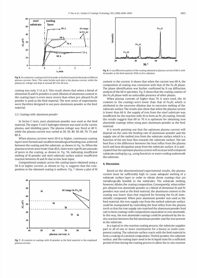
Compositional analysis across the coating layers obtained using a
50 A or higher current, as shown in Fig. 6, suggests that the com-
position in the obtained coating is uniform. Fig. 7 shows a plot of Al
content vs the current. It shows that when the current was 60 A, the
composition of coating was consistent with that of the Fe3Al phase
The phase identification was further confirmed by X-ray diffraction
analysis of the 60 A specimen. Fig. 8 shows that the coating consists of
the Fe3Al phase with no noticeable presence of other phases.
When plasma currents of higher than 70 A were used, the Al
contents in the coatings were lower than that of Fe3Al, which is
attributed to the excessive dilution due to excessive melting of the
substrate surface. The results also show that when the plasma current
is lower than 60 A, the supply of iron from the steel substrate was
insuf ficient for the reaction with Al to form an Fe3Al coating. Overall
the results suggest that 60 to 70 A is optimum for obtaining iron
aluminide coatings when using pure aluminum powder as the feed
material.
It is worth pointing out that the optimum plasma current will
depend on the ratio the feeding rate of aluminum powder and the
supply rate of the melted iron from the substrate surface which is a
function of the net heat flux towards the substrate surface. The net
heat flux is the difference between the heat influx from the plasma
torch and heat dissipation away from the substrate surface. It is anti-cipated that the optimum plasma current will increase with enhanced
substrate cooling by, e.g., using forced air or water cooling underneath
the substrate.
4. Discussion
Based on the aforementioned experimental results, the plasma
current must be suf ficiently high to cause adequate melting of a
substrate surface layer in order to obtain dense coatings that are
metallurgically bonded to the substrates. The substrate melting
however, dilutes the coating composition. Consequently, when either
pre-alloyed iron aluminide powder or a blend of elemental Al and Fe
powders was used as the feed material, the aluminum content in the
coating was lower than that required for forming the Fe3Al inter-metallic compound. When pure aluminum powder was used as the
feed material, the iron supply rate from the melted substrate surface
could be manipulated by controlling the heat influx from the plasma
torch so that the iron supply rate matched the aluminum powder feed
rate to form coatings with compositions equivalent to iron aluminide
In this way, the iron aluminide coatings could be produced by the in-
situ reaction between the fed aluminum powder and the iron present
in the substrate.
In a typical in-situ reaction coating process, the substrate supplies
part or all of one or more constituents for a binary or multi-com-
ponent coating. The substrate surface reacts with the feed material to
form a coating of a desired composition. Thefed powder, the substrate
surface, and the coating layer need to be in liquid state for a suf ficient
period of time during the coating process to allow the in-situ reaction
Fig. 6. Al contentsin coatings(with Al powder as thefeed material)obtained at different
plasma currents. Note: The value beside each plot is the plasma current, while the
plasma arc voltage was kept at around 40 V for all tests.
Fig. 7. Al contents in coatings with Al powder as the feed material vs the employed
plasma currents.
Fig. 8. X-ray diffraction pattern of the coating obtained at plasma current of 60 A, with
Al powder as the feed material. With Cu Kα radiation.
6093P. Fan et al. / Surface & Coatings Technology 202 (2008) 6090–6094

5/9/2018 FAN (2008) - Iron Aluminide Coatings by an in-situ Reaction Process - slidepdf.com
http://slidepdf.com/reader/full/fan-2008-iron-aluminide-coatings-by-an-in-situ-reaction-process 5/5
to be completed. Otherwise, unreacted powder may remain in the
coating layer, resulting in a coating of low quality. Therefore, a
suf ficiently high heat influx towards the substrate surface is necessary
for the success of an in-situ reaction coating process. In this respect,
the PTA technique is uniquely suitable compared to other thermal
spray techniques, because thePTA torch is designed to offer a heat flux
towards thesubstrate high enough for the substrate surface to melt. In
other thermal spray coating processes, such as arc spray [21], low
pressure plasma spray [22], air plasma spray [23] and high velocityoxyfuel (HVOF) spray [24–28], the torches are designed to operate
with a “cold” (in comparison to the melting point of the substrate)
substrate surface and thus no surface melting can occur. It is
interesting to note that the dilution from the substrate, which is
inevitable in the PTA process and usually regarded as a disadvantage
in comparison with other thermal spray techniques, is a pre-requisite
for an in-situ reaction coating process to be successful.
Finally, it is noted that the principles of the in-situ reaction coating
process demonstrated in this research are applicableto the production
of coatings based on other binary or multi-component intermetallic
and alloy systems. For example, NiAl coatings can be formed on Ni or
Ni-based alloy substrates by using Al powder as the feed material; or
FeCrAl coatings can be formed on steel substrates by using a blend of
elemental powders of Al and Cr.
5. Summary
A novel in-situ reaction process for depositing iron aluminide
coatings on steel substrates was developed. In this process, aluminum
powder is fed through a plasma transferred arc (PTA) torch onto the
steel substrate surface. Experimental results demonstrated that the
iron aluminide coating is formed by an in-situ reaction between the
aluminum powder and the steel substrate. Coatings prepared under
optimum conditions were phase-pure iron aluminide that is porosity-
free and metallurgically bonded to the steel substrate. However,
coatings prepared under similar conditions using commercial Fe3Al
powder or blended elemental Fe and Al powders did not yield
adequate coatings. It is expected that the principle demonstrated in
this process canbe applied to thedeposition of other intermetallic and
alloy coatings.
Acknowledgements
The authors acknowledge U.S. Department of Energy for financial
support of this study through Grant number DE-FG26-05NT42529.
References
[1] N.S. Stoloff, Mater. Sci. Eng. A258 (1998) 1.[2] U. Prakash, R.A. Buckley, H. Jones, C.M. Sellars, ISIJ Int. 31 (1991) 1113.[3] C.G. McKamey, J.H. DeVan, P.F. Tortorelli, V.K. Sikka, J. Mater. Res. 6 (1991) 1779.[4] P.F. Tortorelli, K. Natesan, Mater. Sci. Eng. A258 (1998) 115.[5] R. Viswanathan, W.T. Bakker, J. Mater. Eng. Perform. 10 (2001) 81.[6] P. Tomaszewicz, G.R. Wallwork, Oxid. Met. 19 (1983) 165.[7] N. Babu, R. Balasubramaniam, A. Ghosh, Corros. Sci. 43 (2001) 2239.[8] R. Prescott, M.J. Graham, Oxid. Met. 38 (1992) 73.[9] W.D. Cho, I. Kim, H.J. Kim, J. Mater. Sci. 35 (2000) 4695.
[10] K.R. Luer, J.N. DuPont, A.R. Marder, Corrosion. 56 (200 0) 189.[11] J.H. DeVan, P.F. Tortorelli, Corros. Sci. 35 (1993) 1065.[12] P.F. Tortorelli, J.H. DeVan, Mater. Sci. Eng. A153 (1992) 573.[13] P.C. Patnaik, W.W. Smeltzer, J. Electrochem. Soc. 132 (1985) 1226.[14] B.A. Pint, Y. Zhang, P.F. Tortorelli, J.A. Haynes, I.G. Wright, Mater. High Temp 18
(2001) 185.[15] C. Christoglou, N. Voudouris, G.N. Angelopoulos, Surf. Coat. Technol. 155 (2002) 51.[16] L. Sanchez, F.J. Bolivar, M.P. Hierro, J.A. Trilleros, F.J. Perez, Surf. Coat. Technol. 201
(2007) 7626.[17] R. Sivakumar, E.J. Rao, Oxid. Met. 17 (1982) 391.[18] R. Mevrel, C. Duret, R. Pichoir, Mater. Sci. Technol. 2 (1986) 201.[19] L. Levin, A. Ginzburg, L. Klinger, T. Werber, A. Katsman, P. Schaaf, Surf. Coat. Techol.
106 (1998) 209.[20] Z.D. Xiang, P.K. Datta, Acta Mater. 54 (2006) 4453.[21] B.H. Tian, B.S. Xu, S.N. Ma, W. Zhang, J.Z. Hu, X.B. Liang, in: Y.C. Zhou, Y.X. Gu, Z. Li
(Eds.), Mechanics and Materials Engineering for Science and Experiments,Changsha/Zhangjiajie, China, 2001, p. 417.
[22] N. Masahashi, S. Watanabe, S. Hanada, ISIJ Int. 41 (2001) 1010.
[23] R.N.Wright,J.R. Fincke, W.D. Swank, D.C. Haggard,C.R. Clark, in: N.B.Dahortre, J.M.Hampikian, J.J. Stiglich (Eds.), Elevated Temperature Coatings: Science andTechnology I, TMS, Warrendale, PA, 1995, p. 157.
[24] J.R. Blackford, R.A. Buckley, H. Jones, C.M. Sellars, D.G. McCartney, A.J. Horlock, J. Mater. Sci. 33 (1998) 4417.
[25] T. Grosdidier, H.L. Liao, A. Tidu, in: C.C. Berndt (Ed.), Thermal Spray: SurfaceEngineering Via Applied Research, ASM International, Materials Park, OH, 2000,p. 1341.
[26] T.C. Totemeier, R.N. Wright, W.D. Swank, J. Therm. Spray Tech. 11 (2002) 400.[27] B. Szczucka-Lasota, B. Formanek, A. Hernas, J. Mater. Process. Technol. 164 (2005)
930.[28] J.M. Guilemany, N. Cinca, S. Dosta, C.R.C. Lima, Intermetallics 15 (2007) 1384.[29] T. Owa, T. Shinoda, Y. Katoh, J. Jpn. Inst. Met. 65 (2001) 509.[30] T. Owa, T. Shinoda, J. Jap. Welding Soc. 22 (2004) 494.[31] R. Hultgren, P. Desai, D.T. Hawkins, M. Gleiser, K.K. Kelley, Selected Values of the
Thermodynamic Properties of Binary Alloys, ASM, Metals Park, Ohio, 1973, p. 161.
6094 P. Fan et al. / Surface & Coatings Technology 202 (2008) 6090–6094