f&s - book
TRANSCRIPT

FEATURES AND SPECIFICATIONS MANUAL
Xen Alpha™Xen Alpha™Xen Alpha™Xen Alpha™
NEC Australia Pty Ltd
A6-506000-642-02Release 1.0
February 2000

This page is intentionally blank.
Page ii Features and Specifications ManualA6-506000-642-02

Xen Alpha Release 1.0
Disclaimer
NEC shall not be liable for any direct, indirect, consequential or incidental damages about the use of this equipment, manual or any related materials.
The information in this technical manual is advisory in nature and is subject to change. NEC may make improvements and changes in the products described in this manual without notice. Changes will be periodically made to the information in the new editions.
Efforts have been made to ensure that the contents of this manual are correct. Should you find any error, NEC welcomes your comments to improve our communications, please contact NEC on 1800 036 136.
Contents of this manual are subject to change without prior notice at the discretion of NEC Australia Pty Ltd.
This document has been prepared for the use of employees and customers of NEC Australia Pty Ltd and may not be reproduced without the prior, written approval of NEC Australia Pty Ltd.
Copyright 1999
NEC Australia Pty Ltd635 Ferntree Gully RoadGlen Waverley Vic 3150
Integrated Communication Products Group
Installation Manual • • • Preface & Disclaimer Page iiiA6-506000-642-02

This page is intentionally blank.
Page iv Preface & Disclaimer • • • Installation ManualA6-506000-642-02

Features and SpecificA6-506000-642-02
Xen Alpha Release 1.0
Table of Contents
IntroductionXen System Features Introduction . . . . . A0-1
AAAAAll Call Page. . . . . . . . . . . . . . . . . . . . . . . A1-3Ancillary Device Connection . . . . . . . . . . A2-5Answer Hold. . . . . . . . . . . . . . . . . . . . . . . A3-7Answer Key . . . . . . . . . . . . . . . . . . . . . . . A4-9Attendant Positions . . . . . . . . . . . . . . . . A5-11Automatic Callback . . . . . . . . . . . . . . . . A6-13Automatic Day/Night Mode Switching . . A7-15Automatic Hold. . . . . . . . . . . . . . . . . . . . A8-17Automatic Pause – Behind PBX. . . . . . . A9-19Automatic Redial . . . . . . . . . . . . . . . . . A10-21Automatic Release . . . . . . . . . . . . . . . . A11-23
BBBBBackground Music – External Speakers B1-25Background Music – Multiline Telephone Speakers . . . . . . . . . . . . . B2-27Barge-In (Interrupting an External Call) . B3-29Battery Backup – System Memory. . . . . B4-31Battery Backup – System Power . . . . . . B5-33Busy Lamp Field – Multiline Telephones B6-35
CCCCCallback Request . . . . . . . . . . . . . . . . . . C1-37Call Elapsed Timer. . . . . . . . . . . . . . . . . C2-29Call Forward – All Calls . . . . . . . . . . . . . C3-41Call Forward – Busy/No Answer . . . . . . C4-43Call Forward – External . . . . . . . . . . . . . C5-47Caller Identification. . . . . . . . . . . . . . . . . C6-51Caller ID Scrolling . . . . . . . . . . . . . . . . . C7-53Call Pickup Group . . . . . . . . . . . . . . . . . C8-55Call Restriction . . . . . . . . . . . . . . . . . . . . C9-57Call Restriction Override using System Speed Dial . . . . . . . . . . . . . . . . . . . . C10-59Call Transfer. . . . . . . . . . . . . . . . . . . . . C11-61Call Waiting Indication . . . . . . . . . . . . . C12-63Character Registration . . . . . . . . . . . . . C13-65
Clock/Calendar Display . . . . . . . . . . . . C14-69Confirmation Dial. . . . . . . . . . . . . . . . . C15-71Conference Add-On . . . . . . . . . . . . . . C16-73Consecutive Speed Dial . . . . . . . . . . . C17-77
DDDDDelayed Ringing . . . . . . . . . . . . . . . . . . D1-79Direct Inward Termination . . . . . . . . . . . D2-81Direct Paging Access . . . . . . . . . . . . . . D3-83Direct Station Selection . . . . . . . . . . . . . D4-85Distinctive Ringing. . . . . . . . . . . . . . . . . D5-87Door Lock Release . . . . . . . . . . . . . . . . D6-89Door/Monitor Telephone . . . . . . . . . . . . D7-91Do Not Disturb (DND) . . . . . . . . . . . . . . D8-93DP to DTMF Switching . . . . . . . . . . . . . D9-95
EEEEExtension Hunting . . . . . . . . . . . . . . . . . E1-97Extension Name Assignment . . . . . . . . E2-99External Paging (Meet-Me) . . . . . . . . . E3-101External Ringer . . . . . . . . . . . . . . . . . . E4-103
FFFFFlash Key . . . . . . . . . . . . . . . . . . . . . . .F1-105Flexible Line Key . . . . . . . . . . . . . . . . . .F2-107Flexible Numbering Plan . . . . . . . . . . . .F3-109Flexible Ringing Assignment . . . . . . . . .F4-111Flexible Timeout . . . . . . . . . . . . . . . . . .F5-113Full Handsfree Operation . . . . . . . . . . .F6-117
HHHHHandset Microphone Control. . . . . . . . H1-119Handsfree Answerback . . . . . . . . . . . . H2-121Handsfree Dialling and Monitoring . . . H3-123Headset Connection . . . . . . . . . . . . . . H4-125Holdfree Transfer . . . . . . . . . . . . . . . . H5-127Hold with Recall (Exclusive and Non-Exclusive) . . . . . . . . . . . . . . . . H6-129Howler Tone Service . . . . . . . . . . . . . . H7-131
ations Manual Page v

Page vi
IIIIIcon Display . . . . . . . . . . . . . . . . . . . . . . I1-133I-Hold Indication . . . . . . . . . . . . . . . . . . . I2-135Incoming Call Identification . . . . . . . . . . I3-137Internal Recall . . . . . . . . . . . . . . . . . . . . I4-139Internal Voice/Tone Signaling . . . . . . . . I5-141Internal Zone Paging . . . . . . . . . . . . . . . I6-143ISDN Basic Rate Interface . . . . . . . . . . . I7-145ISDN Malicious Call Trace . . . . . . . . . . . I8-147I-Use Indication . . . . . . . . . . . . . . . . . . . I9-149
KKKKKey Function/Multifunction RegistrationK1-151
MMMMManual Line Seizure . . . . . . . . . . . . . . M1-153Manual Pause . . . . . . . . . . . . . . . . . . . M2-155Microphone Control . . . . . . . . . . . . . . . M3-157Music on Hold . . . . . . . . . . . . . . . . . . . M4-159
NNNNNesting Dial . . . . . . . . . . . . . . . . . . . . . N1-161Night Mode. . . . . . . . . . . . . . . . . . . . . . N2-165
OOOOOff-Hook Ringing . . . . . . . . . . . . . . . . . O1-169One-Touch/Feature Access Keys – User Programmable . . . . . . . . . . . . . O2-173
PPPPPC Programming . . . . . . . . . . . . . . . . . P1-175Power Failure Transfer. . . . . . . . . . . . . P2-177Preset Dialling . . . . . . . . . . . . . . . . . . . P3-179Prime Line Assignment . . . . . . . . . . . . P4-181Privacy On All Calls . . . . . . . . . . . . . . . P5-183Programmable Pause for Speed Dial. . P6-185Programming from Multiline Telephone P7-187
RRRRResident System Program . . . . . . . . . . R1-189Ringing Line Preference. . . . . . . . . . . . R2-191Room Monitor Telephone. . . . . . . . . . . R3-193
SSSSSeized Trunk Name/Number Display . S1-195Single Line Telephone Access . . . . . . S2-197Single Line Telephone Adapter . . . . . . S3-199Six/Sixteen Point Capacity . . . . . . . . . S4-201Softkeys. . . . . . . . . . . . . . . . . . . . . . . . S5-203SPD (Redial) Key . . . . . . . . . . . . . . . . S6-205Specified CO/PBX Line Seizure . . . . . S7-209Speed Dial – Station . . . . . . . . . . . . . . S8-211Speed Dial – System. . . . . . . . . . . . . . S9-215Station Message Detail Recording (SMDR) . . . . . . . . . . . . S10-219Step Call . . . . . . . . . . . . . . . . . . . . . . S11-221Stored Hookflash. . . . . . . . . . . . . . . . S12-223
TTTTTelephone Volume Control . . . . . . . . . .T1-225Tenant Service . . . . . . . . . . . . . . . . . . .T2-227Timed Alarm . . . . . . . . . . . . . . . . . . . . .T3-229Tone Override . . . . . . . . . . . . . . . . . . . .T4-231Trunk Outgoing Restriction . . . . . . . . . .T5-233Trunk Queuing. . . . . . . . . . . . . . . . . . . .T6-235Two-Color LEDs (Lamp) . . . . . . . . . . . .T7-237
UUUUUser Programming . . . . . . . . . . . . . . . U1-239
AppendicesAppendix A . . . . . . . . . . . . . . . . . . . . . . . . 241Appendix B . . . . . . . . . . . . . . . . . . . . . . . . 245Appendix C . . . . . . . . . . . . . . . . . . . . . . . . 249
Features and Specifications ManualA6-506000-642-02

Xen Alpha Release 1.0
A-0 Xen System Features Introduction
INTRODUCTION This section describes each feature and its operation. Features are listed alphabetically byfeature name.
DIFFERENCES INTELEPHONE
TYPES
In this chapter the operations are written showing the keys on the DTU-Type telephones.Unless otherwise noted, the same key is also used on the DTU-Type or ETW-Typetelephones. Table A1-1: DTU-Type, DTB-Type and ETW-Type Telephone Keys shows thekeys on the different telephones. In some cases, keys on the different types of telephonesmay perform the same function but are labelled differently. For example, the key used forspeed dialling is labelled T on the DTB-Type telephones and Q on the DTU-Typetelephones.
Table A1-1: DTU-Type, DTB-Type and ETW-Type Telephone Keys
DTB-Type Keys DTU-Type Keys ETW-Type Keys
A A A
B B B
C C C
D D D
E E E
F F F
G G G
H H H
I I I
J 0 K
K J J
Features & Specifications Manual, A-0, Page 1A6-506000-642-02

L L L
M U T
N P Q
O T N
P R O
Q S M
R O R
S Q P
T Q
U N S
V W W
▲ or ▼ M UV
Table A1-1: DTU-Type, DTB-Type and ETW-Type Telephone Keys
DTB-Type Keys DTU-Type Keys ETW-Type Keys
Page 2, A-0 Feature & Specifications, A6-506000-642-02

Xen Alpha Release 1.0
A-1 All Call Page
FEATURE
DESCRIPTION
All Call Page allows simultaneous paging (internal and external) of all idle Multilinetelephones. The page is heard over the built-in speaker on the telephone and/or overexternal paging speakers.
Paging allows persons, away from their desk but within hearing distance of the telephone orexternal speakers to respond to a page. The user can answer the page by dialling aspecified number.
STATION
APPLICATION
Multiline telephones can initiate, receive and answer a page. Single Line telephones can notreceive a page, but can answer or initiate a paging call.
OPERATION
PROCEDURE
1. Go off-hook.
2. Dial G G.
3. Page.
4. Go on-hook.
1. Go off-hook.
2. Dial G D and answer the call.
RELATED
PROGRAMMING
All programming functions associated with this feature are listed in the following table. Somefunctions must be programmed before the feature is operational and other functions areoptional. The optional functions can affect how the feature operates.
Paging:
Answering a page:
Function Number
Function NameRequired(Y)es or
(N)o
002-2 External Speaker Connection N
002-3 External Paging Tone Assignment N
002-4 Internal All Call Page Receive N
001-0 General Purpose Relay Assignment N
217 Internal Paging Tone Assignment N
Features & Specifications Manual, All Call Page A-1, Page 3A6-506000-642-02

SERVICE
CONDITIONS
! All Call Paging is directed only to telephones when “No External Speaker” is specified insystem programming.
! A busy condition is generated if an All Call Page (internal or external) has beenoriginated at another telephone.
! If an external paging call is made while a ringing tone is being sent over the externalspeaker, ringing is temporarily suspended and the external paging call is performed.Ringing resumes after the page is completed.
! All Call Paging is supported for single line telephones. Single line telephones can beused to answer an All Call Page.
! A tone burst is generated as an alert tone to indicate the page.
Page 4, A-1 Feature & Specifications, All Call PageA6-506000-642-02

Xen Alpha Release 1.0
A-2 Ancillary Device Connection
FEATURE
DESCRIPTION
This feature allows ancillary (peripheral) devices such as tape recorders, headsets, singleline telephones, to be connected to the system.
STATION
APPLICATION
The feature is only available when using the DTU-Type Multiline telephones.
OPERATION
PROCEDURE
SERVICE
CONDITIONS
! When using ancillary equipment, the following units can be installed to provideconnection to the system.
! Headset and handsfree units cannot be used simultaneously.
! The APR-UA Unit can only be connected to DTMF (touchtone) telephones.
Refer to the operation for the device that is being connected.
Unit Description
ACA-UA Unit AC Adapter – an AC adapter for use with the APR-A Unit, CTA-UA Unit, or HFU-UA Unit.
ADA-UA Unit Ancillary Device Adapter – provides connection for cassette recorders.
APR-UA Unit Analogue Port Ringer – provides connection for a single line telephone or modem.
CTA-UA Unit Computer Telephony Adapter (or TAPI – Microsoft Telephony Application Programming Interface) – provides connection for a PC.
HFU-UA Unit Handsfree Unit – provides connection for headsets allowing handsfree operation .
Features & Specifications Manual, Ancillary Device Connection A-2, Page 5A6-506000-642-02

This page is intentionally blank.
Page 6, A-2 Features & SpecificationsA6-506000-642-02

Xen Alpha Release 1.0
A-3 Answer Hold
FEATURE
DESCRIPTION
Answer Hold allows the Multiline telephone user to answer an external call by pressing theanswer key (R). If the user is on a call, that call is placed on hold when the new callis answered.
STATION
APPLICATION
This feature is available for all Multiline telephones.
OPERATION
PROCEDURE
1. Press R to answer the call. If already engaged on a call, the existing call is placedon hold.
SERVICE
CONDITIONS
! On DTU-Type telephones, the Answer Key (O) LED flashes when there is anexternal line ringing. The Answer Key (R) on the DTB-Type telephones does not havean LED.
! If using the Answer Key ( R) to answer an internal or external call, and the existing callis an internal call, doorphone call, or paging call; the existing call is disconnected.
! The Answer Key (O) on DTU-Type telephones does not flash when an internal callis received.
! The Answer Key (O) on DTU-Type telephones does not flash when an external callis received at another Multiline telephone.
! The Answer Key (O) on DTU-Type telephones does not flash during a ringingtransfer call.
! This feature is not available during Automatic Redialling or conference calling.
! Incoming trunk calls are answered on a first-in-first-out basis when using theAnswer Key.
Answering a call when a call is in progress:
Features & Specifications Manual, Answer Hold A-3, Page 7A6-506000-642-02

This page is intentionally blank.
Page 8, A-3 Features & SpecificationsA6-506000-642-02

Xen Alpha Release 1.0
A-4 Answer Key
FEATURE
DESCRIPTION
Users answer trunk calls by simply pressing one key; the Answer Key (R).
STATION
APPLICATION
This feature is available for all Multiline telephones.
OPERATION
PROCEDURE
1. Press Rand N or lift the handset.
RELATED
PROGRAMMING
All programming functions associated with this feature are listed in the following table. Somefunctions must be programmed before the feature is operational and other functions areoptional. The optional functions can affect how the feature operates.
SERVICE
CONDITIONS
! If more than one call rings into the system, the system processes the calls in the orderthey are received. As a result, when the user presses R, calls are answered in theorder they are received (first-in-first-out).
! If there is no external ringing call and R pressed, “[BUSY]” is displayed in thetelephone LCD and a busy tone is heard.
! Incoming external calls to other tenant groups cannot be answered by pressing R (ringtone is not provided for these calls).
! On DTU-Type telephones, the Answer Key (O) LED flashes. When an incomingexternal call is received, the red LED flickers at a higher speed to differentiate from othertypes of calls. The Answer Key (R) on the DTB-Type telephones does not havean LED.
! An DTU-Type telephone must be programmed to provide an audible ring tone forincoming calls before the O LED will flash.
! ICM, DID, DIT and CO Ring Transferred calls will not flash the Answer Key LED and theAnswer Key cannot be used to answer these types of calls.
Answering a call:
Function Number
Function NameRequired(Y)es or
(N)o
301 → 306 Day Ringing for Trunk Lines 1 → 6 N
311 → 316 Night Ringing for Trunk Lines 1 → 6 N
Features & Specifications Manual, Answer Key A-4, Page 9A6-506000-642-02

This page is intentionally blank.
Page 10, A-4 Features & SpecificationsA6-506000-642-02
Xen Alpha Release 1.0
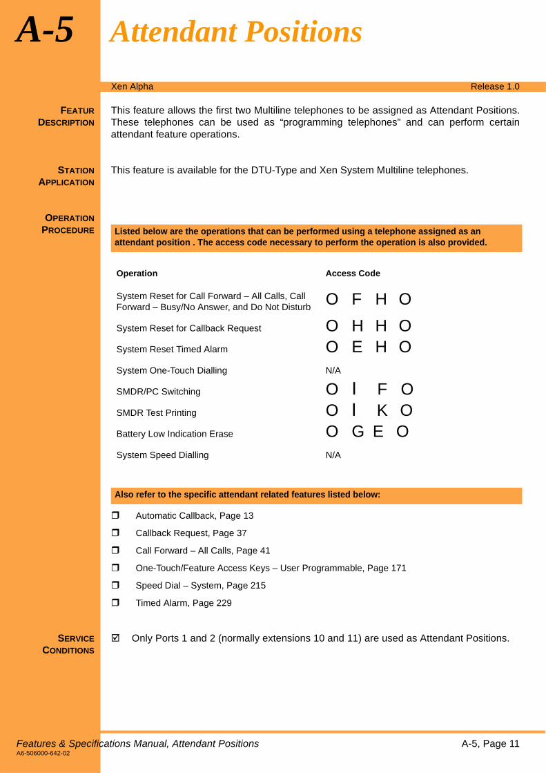
A-5 Attendant Positions
FEATUR
DESCRIPTION
This feature allows the first two Multiline telephones to be assigned as Attendant Positions.These telephones can be used as “programming telephones” and can perform certainattendant feature operations.
STATION
APPLICATION
This feature is available for the DTU-Type and Xen System Multiline telephones.
OPERATION
PROCEDURE
" Automatic Callback, Page 13
" Callback Request, Page 37
" Call Forward – All Calls, Page 41
" One-Touch/Feature Access Keys – User Programmable, Page 171
" Speed Dial – System, Page 215
" Timed Alarm, Page 229
SERVICE
CONDITIONS
! Only Ports 1 and 2 (normally extensions 10 and 11) are used as Attendant Positions.
Listed below are the operations that can be performed using a telephone assigned as an attendant position . The access code necessary to perform the operation is also provided.
Operation Access Code
System Reset for Call Forward – All Calls, Call Forward – Busy/No Answer, and Do Not Disturb
O F H O
System Reset for Callback Request O H H O
System Reset Timed Alarm O E H O
System One-Touch Dialling N/A
SMDR/PC Switching O I F O
SMDR Test Printing O I K O
Battery Low Indication Erase O G E O
System Speed Dialling N/A
Also refer to the specific attendant related features listed below:
Features & Specifications Manual, Attendant Positions A-5, Page 11A6-506000-642-02

This page is intentionally blank.
Page 12, A-5 Features & SpecificationsA6-506000-642-02

Xen Alpha Release 1.0
A-6 Automatic Callback
FEATURE
DESCRIPTION
When calling a busy telephone and hearing a busy tone, users can set an AutomaticCallback. When both telephones are idle, the system signals the person who originated thecallback. When the callback originator answers, the system then signals the other telephoneuser of the call.
STATION
APPLICATION
This feature is available for all telephones and Single Line telephones.
OPERATION
PROCEDURE
1. Go off-hook.
2. Dial the extension number. Busy tone is heard.
3. Dial J.
4. After hearing the set tone, hang up.
SERVICE
CONDITIONS
! If an Automatic Callback is not answered within 30 seconds, the callback is released.
! Automatic Callback can be set for any tenant group.
! Automatic Callback can be set using a single line telephone.
! An individual user can set a maximum of two callbacks from their telephone at one time.
! Only one Automatic Callback be set to a specific telephone; duplicate attemptsare ignored.
! An Automatic Callback can only be answered at the telephone where it is set; otheruser’s cannot pickup the call from their telephones.
! An Automatic Callback cannot be cancelled by the user once it is set.
! When a telephone is in Do Not Disturb mode, Automatic Callback cannot be set.
Setting Automatic Callback when an internal party is called and busy tone is heard:
Features & Specifications Manual, Automatic Callback A-6, Page 13A6-506000-642-02

This page is intentionally blank.
Page 14, A-6 Features & SpecificationsA6-506000-642-02
Xen Alpha Release 1.0
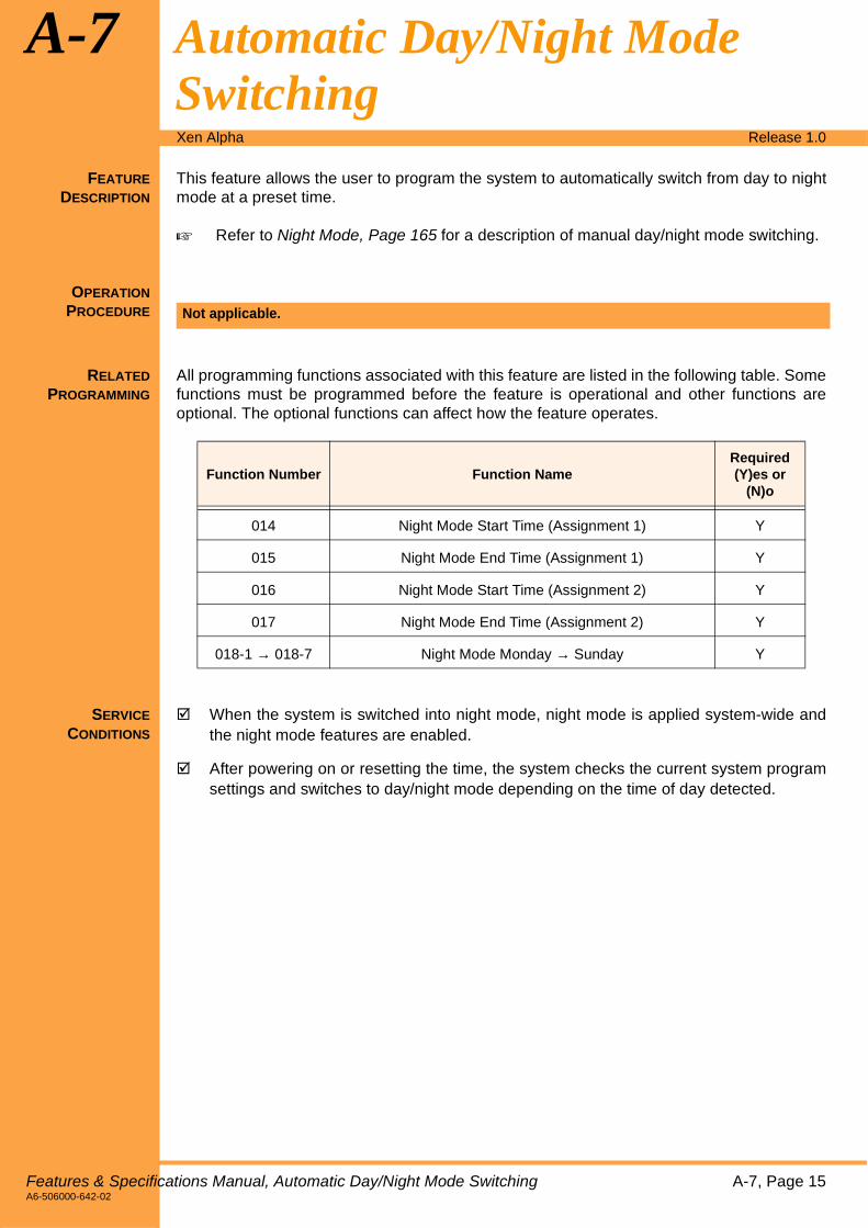
A-7 Automatic Day/Night Mode Switching
FEATURE
DESCRIPTION
This feature allows the user to program the system to automatically switch from day to nightmode at a preset time.
! Refer to Night Mode, Page 165 for a description of manual day/night mode switching.
OPERATION
PROCEDURE
RELATED
PROGRAMMING
All programming functions associated with this feature are listed in the following table. Somefunctions must be programmed before the feature is operational and other functions areoptional. The optional functions can affect how the feature operates.
SERVICE
CONDITIONS
! When the system is switched into night mode, night mode is applied system-wide andthe night mode features are enabled.
! After powering on or resetting the time, the system checks the current system programsettings and switches to day/night mode depending on the time of day detected.
Not applicable.
Function Number Function NameRequired(Y)es or
(N)o
014 Night Mode Start Time (Assignment 1) Y
015 Night Mode End Time (Assignment 1) Y
016 Night Mode Start Time (Assignment 2) Y
017 Night Mode End Time (Assignment 2) Y
018-1 → 018-7 Night Mode Monday → Sunday Y
Features & Specifications Manual, Automatic Day/Night Mode Switching A-7, Page 15A6-506000-642-02

This page is intentionally blank.
Page 16, A-7 Features & SpecificationsA6-506000-642-02

Xen Alpha Release 1.0
A-8 Automatic Hold
FEATURE
DESCRIPTION
This feature allows a user to press a DSS key (Direct Station Selection) to page an internalcaller while an external call is in progress. Once the DSS key is pressed, the external calleris automatically placed on non-exclusive hold.
STATION
APPLICATION
This feature is available for all Multiline telephones.
OPERATION
PROCEDURE
1. While engaged on an external call, press the DSS key for the internal party. Theexternal caller is automatically placed on hold and the internal call is made.
2. Talk with the called party or page the called party.
3. If you want to return to the holding party, press the appropriate line key.
SERVICE
CONDITIONS
! After the preset hold recall timer expires, a hold recall is generated.
Placing a call on Automatic Hold:
Features & Specifications Manual, Automatic Hold A-8, Page 17A6-506000-642-02

This page is intentionally blank.
Page 18, A-8 Features & SpecificationsA6-506000-642-02

Xen Alpha Release 1.0
A-9 Automatic Pause – Behind PBX
FEATURE
DESCRIPTION
When a user places an external call using speed dial, redial, or saved dial through a PBXline, the system automatically inserts a pause into the dialled number.
OPERATION
PROCEDURE
RELATED
PROGRAMMING
All programming functions associated with this feature are listed in the following table. Somefunctions must be programmed before the feature is operational and other functions areoptional. The optional functions can affect how the feature operates.
SERVICE
CONDITIONS
! The pause time is three seconds (fixed).
! The initial value used by the system to indicate a pause is “0 -” (the system dials 0 andinserts a pause).
! A maximum of six digits (three dialled digits and three pauses) can be programmed forthe PBX originating code. However, only one pause can be inserted between digits (i.e.,two pauses cannot be dialled consecutively).
Not applicable.
Function Number
Function NameRequired(Y)es or
(N)o
010 Outgoing Call Access Code for PBX N
Features & Specifications Manual, Automatic Pause – Behind PBX A-9, Page 19A6-506000-642-02

This page is intentionally blank.
Page 20, A-9 Features & SpecificationsA6-506000-642-02

Xen Alpha Release 1.0
A-10 Automatic Redial
FEATURE
DESCRIPTION
Automatic Redial simplifies repeated dialling to a busy telephone or when there is noanswer. When set, redialling is automatically repeated at preassigned intervals. Theintervals are assigned in system programming.
STATION
APPLICATION
This feature is available for all Multiline telephones.
OPERATION
PROCEDURE
1. After receiving a busy tone or when there is no answer, press N.
2. Press O.
3. Press S.
4. The call is redialled automatically. The number of redial attempts is assigned in systemprogramming. (Default = 3)
5. When the called party answers, either lift the handset or press N and begin talking.
Note: If the call is not answered, it is disconnected.
1. Press N or lift the handset, then restore the handset.
- OR -
2. Automatic redial is automatically cancelled when the specified number of redialattempts has been exceeded.
RELATED
PROGRAMMING
All programming functions associated with this feature are listed in the following table. Somefunctions must be programmed before the feature is operational and other functions areoptional. The optional functions can affect how the feature operates.
Setting Automatic Redial:
Cancelling Automatic Redial:
Function Number
Function NameRequired(Y)es or
(N)o
005 Automatic Redial Timer N
Features & Specifications Manual, Automatic Redial A-10, Page 21A6-506000-642-02

SERVICE
CONDITIONS
! If an external call is made using a PBX line, the call elapsed timer displays but does nothave any affect on the Automatic Redial condition.
! When using an ISDN external line, a busy tone is not detected and the line is placed intowait mode until release notification is received. Automatic Redial continues until theprogrammed number of retries is exceeded.
! If the user cancels Automatic Redial during wait mode, the external line is released andthe telephone returns to the idle condition (if the handset is in the cradle and the speakeris off). If the handset is off of the cradle or the speaker is on, internal dialtone is received.
! After the number of redials has exceeded the programmed number of redial attempts, theexternal line is released and Automatic Redialling ends.
! The following operations are allowed during Automatic Redialling. A description of theoperation and the method for initiating the operation are provided below.
! If a call is answered at the telephone where Automatic Redial was initiated, rediallingis cancelled.
! When Automatic Redial is set, the line key LED on the telephone where Automatic Redialis initiated lights green. The line key LED on all other telephones lights red.
! If Automatic Redial is set while the handset is outside the cradle and the handset remains
outside the cradle during redialling, the user must press N to cancel Automatic Redial.
If N is not pressed, Automatic Redial restarts when the user hangs up.
! When outgoing calls are restricted on a line, Automatic Redialling is not allowed. When aAutomatic Redial is attempted using that line, an error tone is generated.
! When a telephone is being used for Automatic Redialling, that telephone cannot be usedto place an external call on hold.
! Barge-in is not allowed while a telephone is being used for Automatic Redialling.
! The user must manually cancel Automatic Redial; the system cannot automatically cancelthe operation. The handset must be lifted off-hook to disable Automatic Redial after anoutside call is answered.
! Automatic Redial can only be set during a call attempt.
Microphone On/Off O + A
Handset Mute On/Off O + B
Automatic Redial Enable O + S
Cancel Automatic Redial Lift Handset (off-hook)
Speaker On Handset in Cradle (on-hook)
Cancel Automatic Redial or Releases External Line
N
Page 22, A-10 Feature & Specifications, Automatic RedialA6-506000-642-02

Xen Alpha Release 1.0
A-11 Automatic Release
FEATURE
DESCRIPTION
This feature signals the system to release the line when an external caller abandons the call.
STATION
APPLICATION
This feature is available for all Multiline telephones and single line telephones.
OPERATION
PROCEDURE
RELATED
PROGRAMMING
All programming functions associated with this feature are listed in the following table. Somefunctions must be programmed before the feature is operational and other functions areoptional. The optional functions can affect how the feature operates.
SERVICE
CONDITIONS
! If a disconnect signal is received, the external line is automatically disconnected.
! If a telephone is disconnected while accessing an external line, the associated line keyLED goes off.
! Automatic Release functions during holding (exclusive/non-exclusive) and conferencecalling.
! When the user is engaged on a single-party call and the external party hangs up, theuser receives a busy tone.
! Analogue trunks provide this feature when the outside exchange generates a “LineReversal on Calling Party Idle” signal, to indicate that the distant aprty has terminatedthe call.
! ISDN trunks are automatically released (standard function) when the distant partyterminates the call.
! Analogue trunks involved in a Call Forward External operation will be automaticallyreleased upon the detection of Busy Tone from either party’s line.
Not applicable.
Function Number
Function NameRequired(Y)es or
(N)o
112 Line Reversal Detection Y
Features & Specifications Manual, Automatic Release A-11, Page 23A6-506000-642-02

This page is intentionally blank.
Page 24, A-11 Features & SpecificationsA6-506000-642-02
Xen Alpha Release 1.0
B-1 Background Music – External Speakers
FEATURE
DESCRIPTION
When connecting with a Background Music (BGM) source, background music is providedover external speakers.
OPERATION
PROCEDURE
RELATED
PROGRAMMING
All programming functions associated with this feature are listed in the following table. Somefunctions must be programmed before the feature is operational and other functions areoptional. The optional functions can affect how the feature operates.
SERVICE
CONDITIONS
! Music is not heard over external speakers unless backgound music speaker connectionis specified in system programming.
! If paging, external ringing, and background music occur at the same time, the systemprioritizes the order they are processed as follows:
1. External Speaker Paging
2. External Ringing
3. Background Music
! The background music source can be either the internal hold tone or an externallyprovided source.
! When connecting external music or speaker equipment, the equipment must beconnected via a Line Isolation Unit with a Telecommunications Compliance label.
Not applicable.
Function Number
Function NameRequired(Y)es or
(N)o
002-2 External Speaker Connection Y
002-6 Background Music Source Y
011 Background Music Destination Y
Features & Specifications Manual, Background Music – External Speakers B-1, Page 25A6-506000-642-02

This page is intentionally blank.
Page 26, B-1 Features & SpecificationsA6-506000-642-02

Xen Alpha Release 1.0
B-2 Background Music – Multiline Telephone Speakers
FEATURE
DESCRIPTION
When connected to a background music (BGM) source, Multiline telephone users can listento music over the Multiline telephone speakers, while the telephone is idle.
This feature is available for all Multiline telephones.
OPERATION
PROCEDURE
1. Press O.
2. Dial I C(background music access code).
3. Press O. Music is heard over the Multiline telephone speakers.
1. Press O.
2. Dial I C(background music access code).
3. Press O. Music is stopped over the Multiline telephone speakers.
RELATED
PROGRAMMING
All programming functions associated with this feature are listed in the following table. Somefunctions must be programmed before the feature is operational and other functions areoptional. The optional functions can affect how the feature operates.
Setting background music when the telephone is idle:
Cancelling background music:
Function Number
Function NameRequired(Y)es or
(N)o
002-6 Background Music Source Y
011 Background Music Destination Y
Features & Specifications Manual, Background Music – Multiline Telephone Speakers B-2, Page 27A6-506000-642-02

SERVICE
CONDITIONS
! Background music toggles between the set and cancel settings each time thebackground music access code is dialed (O I C O).
! Background music volume is controlled by using up (▲) and down (▼) volume controlson the telephone.
! The set/cancel setting is preserved in the backup memory of the telephone.
! If background music has not been specified in system programming, “ERROR” isdisplayed in the telephone LCD when attempting to set background music using the set/cancel access code.
! Background music is heard only when the telephone is in the idle condition. Backgroundmusic is temporarily suspended when the telephone is not idle.
! The background music source can be either the the internal hold tone or an extremelyprovided source.
! The background music source is used for both BGM over External Speakers and BGMover Multiline telephones.
! When connecting external music equipment, the equipment must be connected via aLine Isolation Unit with a Telecommunications Compliance label.
Page 28, B-2 Feature & Specifications, Background Music – Multiline Telephone SpeakersA6-506000-642-02

Xen Alpha Release 1.0
B-3 Barge-In (Interrupting an External Call)
FEATURE
DESCRIPTION
This feature allows one Multiline telephone user to interrupt another user’s conversation.Barge-In can be programmed with or without an audible alert.
STATION
APPLICATION
This feature is available for all Multiline telephones.
OPERATION
PROCEDURE
1. Press N or lift the handset.
2. When you hear dialtone, press O.
3. Press P.
4. Press V (line key) to be interrupted. Barge-In is enabled.
RELATED
PROGRAMMING
Interrupting a conversation using an outside line key:
Function Number
Function NameRequired(Y)es or
(N)o
002-5 Barge-In Notification Tone N
203 Trunk line Barge-IN Y
Features & Specifications Manual, Barge-In (Interrupting an External Call) B-3, Page 29A6-506000-642-02

SERVICE
CONDITIONS
! Barge-in is enabled and disabled in system programming (default is disabled).
! When barge-in is in progress, the conference key ( P ) LED flashes on the telephoneused to initiate barge-in and remains solid on the telephone where barge-in occurs.
! When barge-in is in progress and the user (where barge-in occurs) places their existingcall on hold, the caller who initiated the barge-in is also placed on hold. When the call ispicked up again (taken off of hold), the barge-in caller is also able to resume listening tothe conversation.
! Barge-in also works for telephones programmed to only receive calls (i.e., thosetelephones restricted from dialling out).
! Barge-in is not allowed during the following conditions:
• when Automatic Redial is in progress.
• when dialling is in progress.
• before an internal user answers a call or before the user initiates an outgoing external call.
• all conditions other than an external call in progress (i.e., hold, conference call, etc.).
• the called telephone is a member of a different tenant group.
! A single line telephone cannot be used to initiate a barge-in. However, single linetelephone conversations can be interrupted.
! A telephone cannot be used to initiate a barge-in if it is part of a conference.
! A barge-in cannot be completed if the telephone that is the target of the barge-in is partof a conference.
! If all of the conference circuits in the system are in use, no barge-in is allowed. Barge-inrequires the use of a conference circuit.
! An alert tone is sent to all parties when a Barge-In is originated.
Page 30, B-3 Feature & Specifications, Barge-In (Interrupting an External Call)A6-506000-642-02

Xen Alpha Release 1.0
B-4 Battery Backup – System Memory
FEATURE
DESCRIPTION
A battery is provided on the central processing unit (CPU) in the KSU. This battery retainssystem memory if the power fails. When fully charged, a new lithium battery maintainsbackup power for a minimum two years. This allows the system to return to normal operationonce power is restored.
OPERATION
PROCEDURE
SERVICE
CONDITIONS
! Programming and status condition is retained for the following:
• Background Music
• Call Forward – All Calls
• Call Forward – Busy/No Answer
• Clock/Calendar
• Do Not Disturb
• Incoming Ring Mode for Single Line Telephones (when connected via the ADA-UA unit)
• LCD Contrast (DTU-Type telephones only)
• Microphone Status
• Night Mode
• Redial
• Room Monitor
• Speed Dial Entries (Telephone/System)
• System Data
• Timed Alarms
• Volume
! Status condition is not retained for the following:
• Automatic Callback
• Trunk Queuing
• Off-hook
• Automatic Redial
• Trunk Queing
• Callback Request
! A low battery LCD indication will appear on Multiline terminal Ports 1 and 2 when thelitium battery is low.
! Memory switch SW1 should be set to CLEAR when data is not required to be saved forstorage purposes. This will prolong the life of the lithium battery.
Not applicable.
Features & Specifications Manual, Battery Backup – System Memory B-4, Page 31A6-506000-642-02

This page is intentionally blank.
Page 32, B-4 Features & SpecificationsA6-506000-642-02

Xen Alpha Release 1.0
B-5 Battery Backup – System Power
FEATURE
DESCRIPTION
The built-in backup batteries provide complete system operation for approximately 30minutes. This allows the entire telephone system (key system and telephones) to remainoperational during a power outage.
Externally connected batteries of a larger capacity (max 6.5 Ah) may be installed to obtainlonger backup durations (min 4 hours @ 6.5 Ah).
OPERATION
PROCEDURE
SERVICE
CONDITIONS
! The backup batteries are charged from the Xen System’s power supply.
! Any external equipment requiring their own mains power supply will not be supported bythe backup batteries int he vent of a mains power failure. This includes equipmentconnected to adapters installed in a Multiline terminal.
! Actual backup time provided by the backup batteries will vary depending on systemconfiguration, number of extensions, the amount of operation by users during the powerfailure, etc.
! Batteries must be installed in paris. Refer to the Xen Alpha Installation Manual for batteryspecifications.
Not applicable.
Features & Specifications Manual, Battery Backup – System Memory B-4, Page 33A6-506000-642-02

This page is intentionally blank.
Page 34, B-4 Features & SpecificationsA6-506000-642-02

Xen Alpha Release 1.0
B-6 Busy Lamp Field – Multiline Telephones
FEATURE
DESCRIPTION
The Busy Lamp Field (BLF) is an LED on the Multiline telephone which is used to indicatethe telephone status (idle, in-use, do-not-disturb mode, etc.).
STATION
APPLICATION
This feature is available for all Multiline telephones.
OPERATION
PROCEDURE
SERVICE
CONDITIONS
! Busy Lamp Field indication is provided for the following conditions:
! If a line key is not assigned as a trunk line, it can be assigned as a Busy Lamp Field.These lines must be assigned as “Not Connected” in System Programming.
Not applicable.
Busy Lamp Field Condition
Slow Red Flash Do Not Disturb Set
Telephone in programming mode
Feature Key assignment in progress
Scrolling in progress
Fast Red Flash Call Forward – All Calls Set
Call Forward – Busy/No Answer Set
Solid Red Telephone is busy
Off Telephone is idle
Features & Specifications Manual, Busy Lamp Field – Multiline Telephones B-6, Page 35A6-506000-642-02

This page is intentionally blank.
Page 36, B-6 Features & SpecificationsA6-506000-642-02

Xen Alpha Release 1.0
C-1 Callback Request
FEATURE
DESCRIPTION
This feature is used to leave notification at the called party’s telephone that you have called.
This feature is available for all Multiline telephones (sending and answering Callbackrequest) and single line telephones (sending Callback request only).
STATION
APPLICATION
The single line telephone must be set for Dual Tone Multifrequency mode (touch tone) forthis feature to be used.
OPERATION
PROCEDURE
1. When calling and receiving a busy tone, press K.
Note: When Callback request is set, the O flashes on the calling party’s telephoneand the telephone display (for those telephones equipped with an LCD) at thecalled party’s telephone indicates the calling party’s extension number.
1. Lift the handset or press N.
2. Press L.
1. If the called party does not respond to the Callback, call again.
1. Press O.
2. Dial H H.
3. Press O.
Note: When this procedure is performed, do not disturb and all Call Forward settingsare also cleared.
When cancelling Callback request from an attendant position, all Callbackrequests are cleared system-wide.
Setting a Callback request.
Returning a Callback request:
Cancelling a Callback request from a Multiline telephone:
Cancelling a Callback request from an attendant position:
Features & Specifications Manual, Callback Request C-1, Page 37A6-506000-642-02

SERVICE
CONDITIONS
! A telephone user can set Callback requests to more than one telephone. Callbackrequests can be sent to other telephone users regardless of the tenant group to whichthey belong.
! A telephone that is not equipped with an LCD answers a Callback in the same way usersof telephones equipped with an LCD.
! A maximum of three Callback requests can be set to an individual telephone.
! Single line telephone users can set Callback requests. Single line telephone userscannot receive Callback requests.
! A Callback request can be set to a telephone that has do not disturb set.
! If a power outage occurs, all Callback requests are canceled.
Page 38, C-1 Features & Specifications, Callback RequestA6-506000-642-02

Xen Alpha Release 1.0
C-2 Call Elapsed Timer
FEATURE
DESCRIPTION
This timer appears in the LCD (liquid crystal display) on the Multiline telephone. The timerkeeps track of the amount to time that has elapsed since the call was answered. When theuser hangs up, the timer disappears from the LCD.
STATION
APPLICATION
This feature is available for all Multiline telephones.
OPERATION
PROCEDURE
SERVICE
CONDITIONS
! The call elapsed timer disappears from the LCD when a call is placed on hold (exclusiveand non-exclusive). While the call is on hold, the timer continues counting and isredisplayed when the call is removed from hold, when the call is transferred andanswered, or when the call is transferred and recalls to the telephone that originatedthe transfer.
! The elapsed call time is maintained separately for each external line. When more thanone external line is placed on hold, the timer is redisplayed for each call as it is removedfrom hold.
! During an add-on conference, which includes at least one external line, the elapsed calltime of the last external line that is seized is displayed in the LCD.
! The call elapsed timer is not displayed while a call transfer or tone override is receivedor when dialling is performed during a call using an external line. The call elapsed timerredisplays five seconds after the last digit is dialled.
! During an add-on conference that contains one external line and two internal lines, theelapsed conference time is displayed on the LCD of all the Multiline telephones involvedin the conference.
! The maximum time that can be indicated is 59 minutes and 59 seconds. After 59 minutesand 59 seconds is reached, the timer resets to 00 minutes and 00 seconds.
! The call timer begins counting 10 seconds after seizing an analogue trunk and diallingthe first digit.
! Where Line Reversal on Answer is available on an analogue trunk and that trunk isenabled in function number 112, the call timer will begin counting the moment the outsideparty answers the call.
! The call timer will begin counting immediately the outside party answers the call whenusing an ISDN trunk.
Not applicable.
Features & Specifications Manual, Call Elapsed Timer C-2, Page 39A6-506000-642-02

This page is intentionally blank.
Page 40, C-2 Features & SpecificationsA6-506000-642-02

Xen Alpha Release 1.0
C-3 Call Forward – All Calls
FEATURE
DESCRIPTION
This feature is used to forward calls received at one telephone to another telephone. Thisfeature can also be set or cancelled from the telephone where the calls will be forwarded.Forwarding can be cancelled for the entire system using a telephone assigned as anattendant position.
This feature only applies to internal calls (DID, DIT, ICM and CO Ring Transferred).
STATION
APPLICATION
All stations.
OPERATION
PROCEDURE
1. Press O.
2. Dial F F(access code).
3. Dial the extension number or telephone number where calls will be forwarded.
4. Press O.
1. Press O.
2. Dial K K.
3. Dial K K.
4. Press O.
1. Press O.
2. Dial H.
3. Press O.
1. Press O.
2. Dial F D.
3. Press O.
Setting Call Forward:
Cancelling an individual Call Forward setting:
Cancelling Call Forward system-wide from an attendant (normally extension 10 or 11):
Cancelling Call Forward settings and DND at a station:
Features & Specifications Manual, Call Forward – All Calls C-3, Page 41A6-506000-642-02

SERVICE
CONDITIONS
! All internal and transferred calls to the telephone follow the forwarding settings assignedto that telephone.
! Any telephone in the system can be the Call Forward destination for any number of othertelephones.
! Call Forward – All Calls can be directed to any other telephone in the system even if thetelephone is the member of a different tenant group.
! Any telephone in the system can be set to forward all calls to a voice mail port.
! Call Forward – All Calls settings can be individually reset for each telephone by clearingthe setting using OI I.
! If two internal callers attempt to call one another and they have each other as their CallForward – All Calls destination, a busy tone is generated.
! The Call Forward – All Calls setting takes precedence over the Call Forward – Busy/NoAnswer setting when both are enabled.
! When Call Forward – All Calls is assigned to a One-Touch Key and that key is equippedwith an LED, the LED lights red when the Call Forward feature is enabled.
! If a telephone is programmed for Direct Inward Termination (DIT), allowing calls tobypass the attendant and ring directly at a designated extension, Call Forwarding followsassigned to that telephone.
! On DTB-Type telephones, “Call FWD” is displayed in the telephone LCD when the CallForward – All Calls is enabled.
! Only one Call Forward can be set to the same telephone at one time. The first CallForward must be canceled before setting another Call Forward. If multiple Call Forwarddestinations are entered, only the last destination is valid; all other entries are canceled.
! Only the telephone that is used to originate Call Forward – All Calls can cancel the CallForward – All Calls setting.
! A maximum of two Call Forward destinations can be “chained.” For example, telephoneA is set to forward calls to telephone B and telephone B is set to forward calls totelephone C. Telephone C attempts to forward to D. Telephone C will be the final forwarddestination for both telephones; forwarding to D is not allowed.
! Call Forward – All Calls can be set to an internal and external destinationsimultaneously. In such a case, DID, DIT and CO Ring Transferred calls will forward tothe external destination and ICM calls will forward tot he internal destination.
! A ring assigned trunk call will not follow a Call Forward setting. Only ICM, DID, DIT andCO Ring Transferred calls will follow a Call Forward setting.
Page 42, C-3 Features & Specifications, Call Forward – All CallsA6-506000-642-02

Xen Alpha Release 1.0
C-4 Call Forward – Busy/No Answer
FEATURE
DESCRIPTION
This feature is used to forward calls received at one Multiline telephone to another telephoneor to an Attendant Position. This feature can also be set or canceled from the telephonewhere the calls will be forwarded. This feature only applies to internal calls (DID, DIT, ICM,Co Ring Transferred).
STATION
APPLICATION
All stations.
OPERATION
PROCEDURE
1. Press O.
2. Dial F G.
3. Dial the extension number of the telephone where calls will be forwarded.
4. Press O.
1. Press O.
2. Dial F G.
3. Dial K K.
4. Press O.
1. Press O.
2. Dial F H.
3. Press O.
1. Press O.
2. Dial F D.
3. Press O.
Setting Call Forwarding:
Cancelling an individual Call Forward setting:
Cancelling Call Forward system-wide from an attendant (extension 10 or 11):
Cancelling Call Forward settings and DND at a station:
Features & Specifications Manual, Call Forward – Busy/No Answer C-4, Page 43A6-506000-642-02
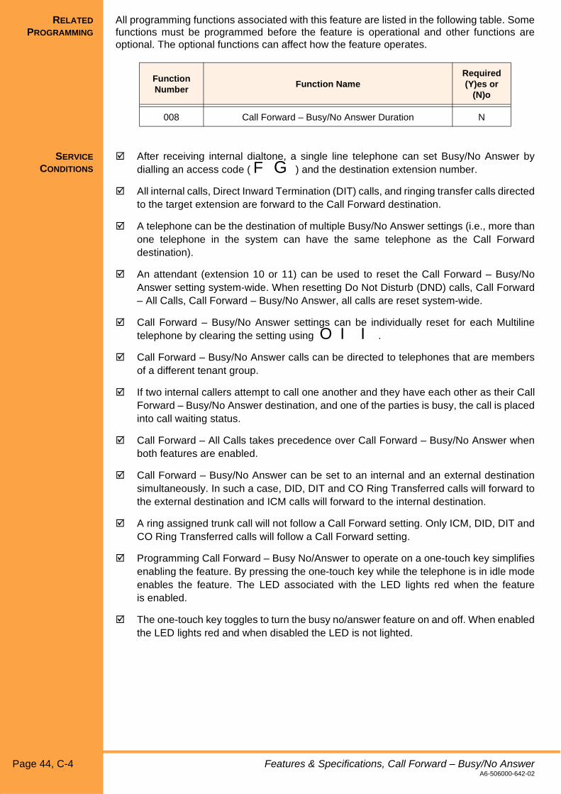
RELATED
PROGRAMMING
All programming functions associated with this feature are listed in the following table. Somefunctions must be programmed before the feature is operational and other functions areoptional. The optional functions can affect how the feature operates.
SERVICE
CONDITIONS
! After receiving internal dialtone, a single line telephone can set Busy/No Answer bydialling an access code ( F G ) and the destination extension number.
! All internal calls, Direct Inward Termination (DIT) calls, and ringing transfer calls directedto the target extension are forward to the Call Forward destination.
! A telephone can be the destination of multiple Busy/No Answer settings (i.e., more thanone telephone in the system can have the same telephone as the Call Forwarddestination).
! An attendant (extension 10 or 11) can be used to reset the Call Forward – Busy/NoAnswer setting system-wide. When resetting Do Not Disturb (DND) calls, Call Forward– All Calls, Call Forward – Busy/No Answer, all calls are reset system-wide.
! Call Forward – Busy/No Answer settings can be individually reset for each Multilinetelephone by clearing the setting using O I I.
! Call Forward – Busy/No Answer calls can be directed to telephones that are membersof a different tenant group.
! If two internal callers attempt to call one another and they have each other as their CallForward – Busy/No Answer destination, and one of the parties is busy, the call is placedinto call waiting status.
! Call Forward – All Calls takes precedence over Call Forward – Busy/No Answer whenboth features are enabled.
! Call Forward – Busy/No Answer can be set to an internal and an external destinationsimultaneously. In such a case, DID, DIT and CO Ring Transferred calls will forward tothe external destination and ICM calls will forward to the internal destination.
! A ring assigned trunk call will not follow a Call Forward setting. Only ICM, DID, DIT andCO Ring Transferred calls will follow a Call Forward setting.
! Programming Call Forward – Busy No/Answer to operate on a one-touch key simplifiesenabling the feature. By pressing the one-touch key while the telephone is in idle modeenables the feature. The LED associated with the LED lights red when the featureis enabled.
! The one-touch key toggles to turn the busy no/answer feature on and off. When enabledthe LED lights red and when disabled the LED is not lighted.
Function Number
Function NameRequired(Y)es or
(N)o
008 Call Forward – Busy/No Answer Duration N
Page 44, C-4 Features & Specifications, Call Forward – Busy/No AnswerA6-506000-642-02

! Multiple one-touch keys can be assigned with different Call Forward destinations. Whena one-touch key is pressed to enable the feature, any previous call destination setting iscanceled. For example, if the user presses a one-touch key where extension 14 is theCall Forward destination and extension 12 is the previous setting, then the setting forextension 12 is canceled. The associated LED for the one-touch key used to setextension 12 as the destination goes off and the associated LED for the one-touch keyused to set extension 14 as the destination lights red.
! If a one-touch key is assigned to a non-existent extension number and the key ispressed, the busy/no-answer settings are preserved but none of the LEDs change. Anerror is displayed in the telephone LCD.
! Call forward Busy/No Answer setting do not follow chained forwarding.
! Only the extension used to set/reset the Call Forward Busy/No Answer setting can beused to change that setting.
! Voice announced calls will not follow the Call Forward Busy/No Answer settings.
Features & Specifications, Call Forward – Busy/No Answer C-4, Page 45A6-506000-642-02

This page is intentionally blank.
Page 46, C-4 Features & SpecificationsA6-506000-642-02

Xen Alpha Release 1.0
C-5 Call Forward – External
FEATURE
DESCRIPTION
The Call Forward External (CFE) feature allows all incoming DID, DIT, AA and CO RingTransferred calls to be automatically forwarded to an external destination. CFE is an extensionof existing Call Forward All and Busy/No Answer functions, where entry of a trunk access coderather than an extension number triggers CFE setting.
STATION
APPLICATION
All stations.
OPERATING
PROCEDURES
1. To off-hook and receive ICM dial tone.
2. Dial the desired Call Forward Access Code:
CF-All 66
CF-B/NA 67
3. Dial the Trunk Access code.
4. Dial the destination telephone number.
5. Go on-hook.
1. Go off-hook and receive ICM dial tone.
2. Dial the desired Call Forward Access Code:
CF-All 66
CF-B/NA 67
3. Dial K K.
4. Go on-hook.
To set CFE:
To cancel CFE:
Features & Specifications Manual, Call Forward – External C-5, Page 47A6-506000-642-02

SERVICE
CONDITIONS
! Call Forward External can be allowed/denied on a per station basis(P229).
! Call Forward External can be allowed/denied on a per trunk basis (P150).
! CFE will operate for DID, DIT and CO Ring Transferred calls. Incoming trunk calls notreceived as a DID call must be changed to DIT before CFE will operate.
! Line Reversal must be enabled for all trunks being used for CFE (P112), including ISDNtrunks.
! Using ‘0’ as a trunk access code will cause CFE to choose a free trunk from thosespecified in P150. The highest available trunk number will be selected. A specific trunk‘X’ may be selected using access code 63X, where X=1 → 6.
! The trunk seized by CFE to establish the outgoing call must be an ISDN trunk or ananalogue COI trunk with Line Reversal on Answer assigned by the service provider.
! A One-Touch key or DSS key can be programmed with the CFE feature. The LEDassociated with this key will remain lit solid red until CFE is cancelled. If multiple CFEkeys are programmed with different destinations, only the key used to set the currentCFE setting will be lit.
! An ERROR will result in the following cases when a station attempts to set CFE. Theseconditions will also be checked before a CFE operation takes place, and the CFE will nottake place if any condition below is met:
• CFE is not allowed for that station
• CFE is not allowed for the specified trunk
• the trunk access code entered is not a valid code
• a TRF card is not installed and the specified trunk or trunk group does not include anISDN trunk
• a TRF card is not installed and there are no ISDN trunks installed in the system
• the analogue trunk or trunk group specified does not include a trunk assigned with BusyTone Detection or Line Reversal Detection
• the station is restricted from making outgoing calls
• the specified trunk is restricted from outgoing calls
• the destination number entered is restricted from that station
! In addition to the conditions noted in the previous point, the Call Forward external willnot proceed if;
• a trunk cannot be seized by the CFE facility because it is busy
• the telephone number for the outgoing call is busy
• an analogue COOI trunk is involved and the TRF channel is busy
! If for whatever reason the CFE operation fails, the extension receiving the call willinstead ring as though the CFE were not set. The CFE operation will not beattempted again.
! When CFE is set on MLT, “EXT FWD SET” will be continuously displayed on its LCDand a special internal dial tone produced when that station goes off-hook.
! When CFE is set on an SLT, a special internal dial tone is produced when that stationgoes off-hook. There is no visual indication of this setting.
! The internal dial tone produced when CFE is set shall be the “Service Set Tone”, a800Hz continuous tone.
! The KTS only answers the incoming call when the diversion is successfully connectedto the external party using the CFE feature.
Page 48, C-5 Features & Specifications, Call Forward – ExternalA6-506000-642-02

! The line on which the incoming call arrives is released when the line used for theoutgoing call is released.
! Call Forward and Call Forward External can both be set at a station. When both are set,DID, DIT and CO Ring Transferred calls will follow CFE, and ICM calls will follow the CFInternal setting.
! When cancelling a Call Forward setting, dialling the code will first cancel a CFE setting.If Call Forward is also set, repeat the Call Forward code if desired.
! A maximum of three CFE calls can be established in the system at one time, with thefollowing calls:
• COI1 to COI2
• ISDN to ISDN
• ISDN to ISDN (??)
! An SMDR report will be produced for the outgoing call of a Call Forward Externaloperation.
! The TRF-B13 ETU will detect busy tone sent from an analogue trunk party to a CFE call.This will cause the CFE call to be disconnected and all trunks of the CFE released.
! The CFE feature takes precedence over any other Call Forward setting.
! During the CFE process, the incoming caller will continue to hear ring tone and the trunkon the KTS will continue to receive ring until the diversion has been successfullycompleted. However during this time no ring indication shall be provided to the KTSextension, other than a flashing red Line Key for the incoming call and a solid red LineKey for the outgoing call. The Line Key of the incoming call shall change to solid red oncethe CFE has been successful.
! A call connected externally using the CFE feature cannot be entered into by any party(e.g. using Barge-In). Both the incoming and outgoing Line Key LEDs will remain solidred on all stations until the trunk has been disconnected and both lines are released bythe KTS.
! An Automatic Disconnect Timer specifies the maximum time a CFE call will remain inplace before being forcibly disconnected. A tone of 800 Hz for 2 seconds will be heardby both parties 30 seconds before the trunks are released by the system.
! Installation of the TRF-B13 ETU (Trunk Transfer card) will be required if analogue COItrunks are involved in the CFE process, either as an incoming or outgoing trunk. If onlyISDN trunks are involved in the CFE process, the TRF card is not required. If a TRF cardis not installed, an incoming call on an analogue trunk will not follow the CFE setting, andan analogue trunk will not be selected as the outgoing trunk.
Features & Specifications, Call Forward – External C-5, Page 49A6-506000-642-02

This page is intentionally blank.
Page 50, C-5 Features & SpecificationsA6-506000-642-02

Xen Alpha Release 1.0
C-6 Caller Identification
FEATURE
APPLICATION
The Caller Identification (Caller ID) feature allows the user to see the calling party’s nameand phone number in their telephone display.
A CID-B13 Unit is required to provide caller identification on analogue trunks. Three CIDunits are required to provide caller identification for all six of these trunks.
Caller ID is available as standard on BRI ISDN trunks.
STATION
APPLICATION
This feature is available for display Multiline telephones.
OPERATION
PROCEDURE
SERVICE
CONDITIONS
! Caller ID uses information sent from the central office and displays the information(name and/or number) in the telephone LCD. If Caller ID information is not provided, thesystem displays the number assigned in system programming to the trunk line.
! The Caller ID information sent from the exchange usually includes the caller’s telephonenumber only, no associated name. For a name to be displayed, the caller’s number andname must be programmed into a System Speed Dial entry. When a call is received thenumber sent is checked against those programmed into System Speed Dial locationsand if there is a match, the associated name will also be displayed.
! When displayed, the caller’s number is shown on the top row of the display and the theirname on the second row of the display. Both the name and number are proceeded bythe trunk line number where the call rings into.
Display Example:
! If the call is an internal call, Caller ID information is not provided from the central office,the system searches the system speed dialling entries and if the number and associatedname is stored in system data, that information is displayed in the telephone LCD.
! There is no system limitation to the number of telephones that can display CallerID information.
! When multiple external calls ring into the system, Caller ID information is stored for eachof the incoming calls. Caller ID information is displayed in the order that the calls aredetected (i.e., the first incoming trunk call is detected and the information is displayeduntil the call is answered; as additional calls are answered, the stored Caller IDinformation is displayed until answered).
Not applicable.
01/92621111
NEC Australia
Features & Specifications Manual, Caller Identification C-6, Page 51A6-506000-642-02

This page is intentionally blank.
Page 52, C-6 Features & SpecificationsA6-506000-642-02

Xen Alpha Release 1.0
C-7 Caller ID Scrolling
FEATURE
DESCRIPTION
When caller identification information is provided, the user can browse through the list of thelast 20 numbers by pressing P and R. The user can dial the displayed Caller ID numberby pressing N or by lifting the handset.
STATION
APPLICATION
This feature is available for all Multiline telephones equipped with a display.
OPERATION
PROCEDURE
1. While the telephone is idle, press P.
2. Press R to display the most recent Caller ID information. The date and time that thecall was received and the caller’s number are displayed.
3. To scroll through the list of Caller ID information, continue to press R .
Note: When the end of the list is reached, the first Caller ID is displayed when Ris pressed.
1. While the Caller ID information is displayed, press V(external line key), lift the handset ,or press N.
SERVICE
CONDITIONS
General
! If no Caller ID information exists, the telephone remains idle when P and Rare pressed.
! If V(external line key) is pressed while scrolling through the Caller ID information, thedisplayed number is dialled.
! When the call is received, both the name and number are displayed (if provided). Whenscrolling only the number is displayed.
Confirming Caller ID information:
Placing a call using the displayed Caller ID information:
Features & Specifications Manual, Caller ID Scrolling C-7, Page 53A6-506000-642-02

This page is intentionally blank.
Page 54, C-7 Features & SpecificationsA6-506000-642-02

Xen Alpha Release 1.0
C-8 Call Pickup Group
FEATURE
DESCRIPTION
This feature allows any user to pickup a call that is intended for another user.
A call pickup group allows telephones in the system to be grouped together so users canpick up incoming calls in that group by dialling a preassigned two digit number. Groups aredefined using tenant assignment.
STATION
APPLICATION
The feature is available for all Multiline telephones and single line telephones.
OPERATION
PROCEDURE
User B performs this procedure to answer a call that is received at user A’s telephone.
1. Go off-hook.
2. Dial the access code. Default access codes are:
F J = Pick up CO/PBX calls ringing in a different tenant group
F A = Pick up ICM/DID/DIT calls ringing in the same tenant group
3. Speak with the calling party.
RELATED
PROGRAMMING
All programming functions associated with this feature are listed in the following table. Somefunctions must be programmed before the feature is operational and other functions areoptional. The optional functions can affect how the feature operates.
Answering a call:
Function Number
Function NameRequired(Y)es or
(N)o
401 Trunk Line Assignment for Tenant 1 N
402 Trunk Line Assignment for Tenant 2 N
403 Telephone-to-Tenant Assignment N
Features & Specifications Manual, Call Pickup Group C-8, Page 55A6-506000-642-02

SERVICE
CONDITIONS
! When there is more than one type of call that rings into the system, the system picks upcalls in the following order:
• Internal Voice/Tone/Call Waiting
• Ringing Transfer
• Incoming External Calls to another Tenant
! If there is more than one call ringing into the system, calls are picked up beginning withthe lowest numbered extension (i.e., if extension 10 and 11 ring at the same time,extension 10 is picked up first).
! If there are no calls and a users attempts to pick up a call using one of the call pick upaccess codes, “BUSY” is displayed in the telephone LCD.
! When more than one Direct Inward Termination (DIT) call rings at a telephone, they arepicked up in the order in which the system first detects the calls.
! External calls picked up by a user in another tenant group can be taken off of hold by theuser who placed them on hold.
! Incoming internal calls call on be picked up by a user in the same tenant group.
! Only ringing transferred calls can be picked up by users who are members of anothertenant group. Once the call is picked up it can be placed on hold and removed from holdas necessary.
Page 56, C-8 Features & Specifications, Call Pickup GroupA6-506000-642-02
Xen Alpha Release 1.0
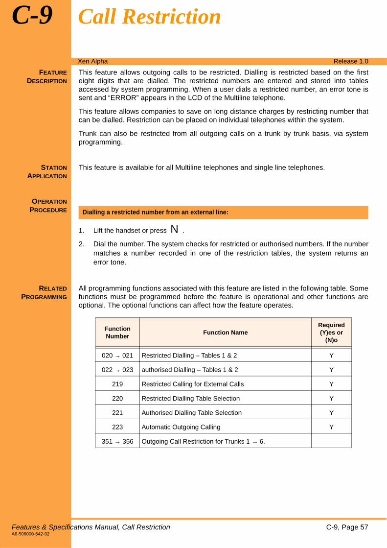
C-9 Call Restriction
FEATURE
DESCRIPTION
This feature allows outgoing calls to be restricted. Dialling is restricted based on the firsteight digits that are dialled. The restricted numbers are entered and stored into tablesaccessed by system programming. When a user dials a restricted number, an error tone issent and “ERROR” appears in the LCD of the Multiline telephone.
This feature allows companies to save on long distance charges by restricting number thatcan be dialled. Restriction can be placed on individual telephones within the system.
Trunk can also be restricted from all outgoing calls on a trunk by trunk basis, via systemprogramming.
STATION
APPLICATION
This feature is available for all Multiline telephones and single line telephones.
OPERATION
PROCEDURE
1. Lift the handset or press N.
2. Dial the number. The system checks for restricted or authorised numbers. If the numbermatches a number recorded in one of the restriction tables, the system returns anerror tone.
RELATED
PROGRAMMING
All programming functions associated with this feature are listed in the following table. Somefunctions must be programmed before the feature is operational and other functions areoptional. The optional functions can affect how the feature operates.
Dialling a restricted number from an external line:
Function Number
Function NameRequired(Y)es or
(N)o
020 → 021 Restricted Dialling – Tables 1 & 2 Y
022 → 023 authorised Dialling – Tables 1 & 2 Y
219 Restricted Calling for External Calls Y
220 Restricted Dialling Table Selection Y
221 Authorised Dialling Table Selection Y
223 Automatic Outgoing Calling Y
351 → 356 Outgoing Call Restriction for Trunks 1 → 6.
Features & Specifications Manual, Call Restriction C-9, Page 57A6-506000-642-02

SERVICE
CONDITIONS
! There are four tables that contain numbers that the system accesses for call restriction:two tables containing restricted numbers (numbers that cannot be dialled) and twotables containing numbers that are authorised (numbers that can be dialled). Eachtelephone can be assigned to access any of the tables or individual telephones can beassigned to access all four tables.
! Each entry in the authorised and restricted tables is a maximum of eight digits. Eachtable can have a maximum of eight entries.
! Individual telephones can be programmed to override the entries in the authorised/restricted tables using speed dialling.
! If the same number is entered in the authorised table and the restricted table, the entryin the restricted table takes precedence.
! At system default, no restrictions are imposed for calling.
Page 58, C-9 Features & Specifications, Call RestrictionA6-506000-642-02

Xen Alpha Release 1.0
C-10 Call Restriction Override using System Speed Dial
FEATURE
DESCRIPTION
This feature allows telephones, which have been be restricted from making outgoing calls,to make calls using the preassigned system speed dial numbers.
STATION
APPLICATION
This feature is available for all Multiline and Single Line telephones.
OPERATION
PROCEDURE
1. Press V(line key programmed to access an outside line).
2. Press T or Q.
3. Dial the desired speed dial memory location.
RELATED
PROGRAMMING
All programming functions associated with this feature are listed in the following table. Somefunctions must be programmed before the feature is operational and other functions areoptional. The optional functions can affect how the feature operates.
SERVICE
CONDITIONS
! 80/20 Speed Dial Mode:
00-20 - Always follows Toll Restriction21-35 - Always bypasses Toll Restriction60-99 - Follows Toll Restriction if P222 = Deny, bypasses Toll Restriction if
P222 = Allow
! 200/0 Speed Dial Mode:
000-200 - Follows Toll Restriction if P222 = Deny, bypasses Toll Restriction ifP222 = Allow
Using call restriction override by dialling a system speed dial number:
Function Number
Function NameRequired(Y)es or
(N)o
222 Authorised Dialling for External Speed Dial Calls Y
001-2 Speed Dial Mode N
Features & Specifications Manual, Call Restriction Override using System Speed Dial C-10, Page 59A6-506000-642-02

This page is intentionally blank.
Page 60, C-10 Features & SpecificationsA6-506000-642-02

Xen Alpha Release 1.0
C-11 Call Transfer
FEATURE
DESCRIPTION
This feature allows any user to transfer an external call to any other system user. The userreceiving the call simply goes off-hook to answer the call. The call can be transferred usingtwo methods:
" A user transfers the call and hangs up. The caller receiving the transferred call hears ringingand answers the call.
" A user transfers a call and waits for the called user to answer. Once the call is verballyannounced, the caller who transferred the call hangs up.
STATION
APPLICATION
This feature is available for all Multiline and Single Line telephones.
OPERATION
PROCEDURE
1. Press M. The call is put on hold.
2. Call the party’s extension where the call will be transferred.
3. Press U or hang up.
1. Press U. The call is put on hold.
2. When you hear the dialtone, dial the party’s extension number where the call willbe transferred.
3. When the called party answers, press U or hang up.
- OR -
When the called party answers, voice announce the transfer and hang up.
- OR -
If the called extension is busy or there is no answer, press the line key where theexternal call is holding or press P to return to the holding internal call.
1. Hookflash.
2. When you hear dialtone, dial the extension number where the call will be transferred.
3. Hang up.
- OR -
If the called extension is busy or the call is denied, retrieve the call bypressing hookflash.
Transferring a call:
Transferring a call with a call in progress:
Transferring a call from a single line telephone with a call in progress:
Features & Specifications Manual, Call Transfer C-11, Page 61A6-506000-642-02

RELATED
PROGRAMMING
All programming functions associated with this feature are listed in the following table. Somefunctions must be programmed before the feature is operational and other functions areoptional. The optional functions can affect how the feature operates.
SERVICE
CONDITIONS
! Outgoing trunk line calls can be transferred.
! Calls can be transferred to extensions that are members of a different tenant.
! If the transferred call is not answered at the destination extension within 30 seconds, thecall recalls to the transferring extension. An alarm tone is generated at the transferringextension and the telephone’s display shows the destination extension number.
! Calls can be transferred to a telephone even when the telephone is busy or is in Do NotDisturb mode.
! A 3-party conference can be established while an outside call is in progress by pressingU and dialling the number. When the party answers, press P.
! When a call is transferred, the outside line key LED flashes green on the destinationtelephone and flashes red on all other telephones in the tenant group.
! Transferred calls follow the Call Forwarding that is on the destination telephone(if enabled).
! A single line telephone cannot be used to transfer a call if Function 001-9 (Single LineTelephone Hookflash Assignment) is set to “Hookflash”.
Function Number
Function NameRequired(Y)es or
(N)o
001-4 Ringing Transfer N
001-5 Automatic Transfer N
001-9 Single Line Telephone Hookflash Assignment N
Page 62, C-11 Features & Specifications, Call TransferA6-506000-642-02

Xen Alpha Release 1.0
C-12 Call Waiting Indication
FEATURE
DESCRIPTION
The system provides a visible indication to the called party that they have an incoming call.This indication allows the user to put the existing call on hold and answer the incoming call,terminate the existing call and answer the incoming call, or ignore the incoming call.
STATION
APPLICATION
This feature is available for all Multiline and Single Line telephones.
OPERATION
PROCEDURE
SERVICE
CONDITIONS
! When an internal call is received, the extension number/name of the user who is callingis displayed in the telephone LCD.
! When an external call is received, the external line where the call is received flashes red.
! An incoming intoner/DID/DIT/CO Ring Transferred call will cause the large 360° LED ofthe Multiline telephone to flash red.
! An incoming trunk call will cause the large 360° LED of a DTU-Type Multiline telephoneto flash green and a DTB-Type Multiline telephone to flash red.
Not applicable.
Features & Specifications Manual, Call Waiting Indication C-12, Page 63A6-506000-642-02

This page is intentionally blank.
Page 64, C-12 Features & SpecificationsA6-506000-642-02
Xen Alpha Release 1.0
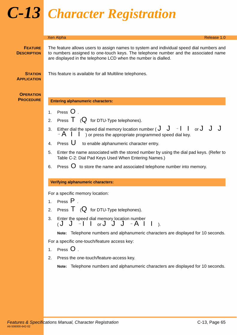
C-13 Character Registration
FEATURE
DESCRIPTION
The feature allows users to assign names to system and individual speed dial numbers andto numbers assigned to one-touch keys. The telephone number and the associated nameare displayed in the telephone LCD when the number is dialled.
STATION
APPLICATION
This feature is available for all Multiline telephones.
OPERATION
PROCEDURE
1. Press O.
2. Press T (Q for DTU-Type telephones).
3. Either dial the speed dial memory location number ( J J → IIor J J J→ A II) or press the appropriate programmed speed dial key.
4. Press U to enable alphanumeric character entry.
5. Enter the name associated with the stored number by using the dial pad keys. (Refer toTable C-2: Dial Pad Keys Used When Entering Names.)
6. Press O to store the name and associated telephone number into memory.
For a specific memory location:
1. Press P.
2. Press T (Q for DTU-Type telephones).
3. Enter the speed dial memory location number( J J → IIor J J J → A II).
Note: Telephone numbers and alphanumeric characters are displayed for 10 seconds.
For a specific one-touch/feature access key:
1. Press O.
2. Press the one-touch/feature-access key.
Note: Telephone numbers and alphanumeric characters are displayed for 10 seconds.
Entering alphanumeric characters:
Verifying alphanumeric characters:
Features & Specifications Manual, Character Registration C-13, Page 65A6-506000-642-02

1. Press O .
2. Press T (Q for DTU-Type telephones).
3. Press the speed dial memory location number( J J IIor J J J → A II).
4. Press Oto delete only the telephone number. Press U and Oto delete thename and number.
Deleting a name and/or telephone number:
Table C-2: Dial Pad Keys Used When Entering Names
Key Usage
K Shifts the cursor one character to the left and deletes the character.
L Creates a blank character to the right of the cursor.
P Toggles between uppercase and lowercase letters.
A 1
B A B C, a b c, or 2
C D E F, d e f, or 3
D G H I, g h i, or 4
E J K L, j k l, or 5
F M N O, m n o, or 6
G P Q R S, p q r s, or 7
H T U V, t u v, or 9
I W X Y Z, w x y z, or 9
J & @ or 0
U Toggles between alphabetic and numeric entry.
T
(Q)‘ - :
Page 66, C-13 Features & Specifications, Character RegistrationA6-506000-642-02

SERVICE
CONDITIONS
! If consecutive speed dialling is used, alphanumeric data in redial memory is changed.
! The input character mode is indicated in the second line of the telephone LCD. Whenonly numeric characters can be entered, “NUMERIC” is displayed in the LCD. Whenalphanumeric characters can be entered, “ALPHA” is displayed in the LCD.
! When a call is originated using speed dialling (whether dialling is done manually or usinga one-touch key assigned a speed dial number) and the speed dial number hasalphanumeric data associated with it, old alphameric data is cleared.
! Alphanumeric characters can be assigned to a speed dial memory location number or aone-touch key.
! Alphanumeric data associated with system speed dialling can only be entered, modifiedor erased using an attendant Multiline telephone (normally extension 10 or 11) or usingPC programming.
! A maximum of 16 characters can be assigned to a speed dial number.
Features & Specifications, Character Registration C-13, Page 67A6-506000-642-02

This page is intentionally blank.
Page 68, C-13 Features & SpecificationsA6-506000-642-02

Xen Alpha Release 1.0
C-14 Clock/Calendar Display
FEATURE
DESCRIPTION
On Multiline telephones equipped with an LCD (liquid crystal display), the time (hour andminutes) and the date (day, day of week and year) are displayed.
STATION
APPLICATION
This feature is available on all Multiline telephones equipped with a display.
OPERATION
PROCEDURE
1. Press O.
2. Dial I L.
3. Press the appropriate dial pad keys to enter the time.
Note: Use K to move the cursor to the left and L to move the cursor to the right.
4. Place the cursor under a.m. or p.m. and press Q (S) to select.
5. Press M to switch between the date and time displays.
6. Press Q (Sfor the Elite telephones) to change the day of the week.
7. Dial L and move the cursor to the date.
8. Using the dialpad, enter the date.
9. Move the cursor to the desired month and press Q (S) to select the month.
10. Dial L and move the cursor to the year.
11. Using the dialpad, enter the year.
12. Press O to save the changes and exit.
RELATED
PROGRAMMING
All programming functions associated with this feature are listed in the following table. Somefunctions must be programmed before the feature is operational and other functions areoptional. The optional functions can affect how the feature operates.
Setting the clock/calendar:
Function Number
Function NameRequired(Y)es or
(N)o
002-7 Time Format for Telephone Display N
Features & Specifications Manual, Clock/Calendar Display C-14, Page 69A6-506000-642-02

SERVICE
CONDITIONS
! Date and time can be changed using any Multiline telephone in the system.
! By default, the clock is set to January 1, 1999 (Friday), 12:00 a.m.
! If P is pressed while setting the date and time, the procedure is canceled and exits.The telephone is returned to the idle condition.
! Leap years are automatically set when the date (year) is specified.
! The time format (12 hour or 24 hour) is set using Function “002-7 – Time Format forTelephone Display”.
! Daylight savings time is not switched automatically, this must be done manually.
! If “99” is entered, the date is 1999. If set 00 → 98 is entered, the date is 2000 → 2098.
Page 70, C-14 Features & Specifications, Clock/Calendar DisplayA6-506000-642-02

Xen Alpha Release 1.0
C-15 Confirmation Dial
FEATURE
DESCRIPTION
This feature allows users to dial a telephone number which is displayed for confirmationduring speed dialling, one-touch dialling, and scrolling caller identification numbers.
STATION
APPLICATION
This feature is available for all Multiline telephones.
OPERATION
PROCEDURE
1. Press P.
2. Press T (Q for DTU-Type telephones).
3. Dial the speed dial memory location number to display the stored telephone number.
4. Press V (the appropriate outside line key) while the telephone number is displayed.The system automatically dials the displayed number.
1. Press O.
2. Press V (one-touch key) you want to confirm.
3. Press V (the appropriate outside line key) while the telephone number is displayed.The system automatically dials the displayed number.
SERVICE
CONDITIONS
! Confirmation dialling is available for the following conditions:
• Speed Dialling (system, extension and nested speed dialling)
• One-Touch Dialling
• Caller ID Scrolling
! Simple searches are possible when speed dial numbers are displayed by using # or ✱.For example, if 19 is displayed and # is pressed, the display scrolls to 20.
# = scrolls to the next stored speed dial number
✱ = scrolls to the previous stored speed dial number
! If an empty speed dial memory location is detected during a simple search, “Empty” isdisplayed in the telephone LCD.
Confirmation dialling using a speed dial memory location number:
Confirmation dialling using a one-touch key:
Features & Specifications Manual, Confirmation Dial C-15, Page 71A6-506000-642-02

! When performing simple searches and the last speed dial memory location number isreached, the system scrolls to the first speed dial memory location number. Forexample, if 199 is displayed (system is set for 200 memory locations) and the userpresses #, the system “rolls over” to 000. If 000 is displayed and ✱ is pressed, the system“rolls back” to 199.
! When calling preference is set to CO/PBX line preference using Function “209 –Outgoing Call Priority Mode”, confirmation dialling is accomplished by lifting the handset.
! Call restriction applies during confirmation dialling.
Page 72, C-15 Features & Specifications, Confirmation DialA6-506000-642-02

Xen Alpha Release 1.0
C-16 Conference Add-On
FEATURE
DESCRIPTION
This feature allows conference calling. A maximum of three parties (various combinations ofinternal and external callers) are allowed in each conference. Conference calling increasesefficiency by allowing multiple parties to enter into a conversation. Music is provided tocallers while they are on hold waiting to enter the conference.
The possible conference combinations are:
" One internal party and two external parties.
" Two internal parties and one external party.
" Three internal parties.
STATION
APPLICATION
This feature is available for all Multiline and Single Line telephones.
OPERATION
PROCEDURE
1. If adding an internal party, dial the party’s extension number. If adding an external party, dialthe party’s telephone number.
2. Press M. The party is put on hold.
3. If adding an internal party, dial the party’s extension number. If adding an external party,press the appropriate line key to access an outside line, then dial the party’stelephone number.
4. Press P to add the caller on hold to the conference.
1. Press hookswitch to place the first party on hold.
2. Dial the party’s extension number.
Note: Only internal callers can be added to a conference when a single line telephoneis used to initiate the conference call.
3. Press hookswitch again to add the holding party to the conference.
Initiating a conference call with a call in progress:
Setting up a conference call using a single line telephone while a call is in progress:
Features & Specifications Manual, Conference Add-On C-16, Page 73A6-506000-642-02

RELATED
PROGRAMMING
All programming functions associated with this feature are listed in the following table. Somefunctions must be programmed before the feature is operational and other functions areoptional. The optional functions can affect how the feature operates.
SERVICE
CONDITIONS
! Barge-In is not allowed for any outside line or telephone that is part of a conference.
! Only one internal party, who is a part of a conference, can put a conference on hold. Thetelephone used to put the conference on hold cannot participate in another conference.
! When a conference consists of two outside lines and one internal line and theconference is put on hold and one of the outside lines is selected, the conference iscanceled. The other outside line is not dropped but is on exclusive hold.
! If Function 106 “Automatic Release of Trunk Line” is enabled in programming and theoutside line is released, the remaining parties continue talking. If automatic release isnot disabled, a busy tone is heard and the conference is terminated.
! When three internal parties are in conference and one of the parties exits theconference, the two remaining parties resume a 2-party call.
! The P LED lights red when a conference is in progress.
! When both of the conference circuits are busy, both of the P LEDs light red.
! When a Multiline telephone is used to place a call on conference hold, the lines keysassociated with the conference hold flashes green (indicating exclusive hold) and theP LED flashes red. On other telephones in the system, the P LED is solid red.
! A 3-party internal conference can also be put on hold.
! When an external line is on hold, recall is provided for single line telephones (if thehandset is placed in the cradle).
! A Single Line telephone user cannot add a trunk to their conference call, but canestablish a conference between themselves and two other internal parties.
Function Number
Function NameRequired(Y)es or
(N)o
106 Automatic Release of Trunk Line N
Page 74, C-16 Features & Specifications, Conference Add-OnA6-506000-642-02

! During a conference call some of the keys on the telephone can be used and somecannot be used, these are listed below.
Available Keys:
O Accesses available functions.
O A Toggles to turn the microphone on and off.
O B Toggles to set and reset handset mute.
M Places a conference on hold.
N Toggles to turn the speaker on and off or cancels a conference.
Unavailable Keys:
V Outside line key that is part of a conference.
V One-touch keys programmed for a function.
P
T or Q
Q or SR
S
U
Features & Specifications, Conference Add-On C-16, Page 75A6-506000-642-02

This page is intentionally blank.
Page 76, C-16 Features & SpecificationsA6-506000-642-02

Xen Alpha Release 1.0
C-17 Consecutive Speed Dial
FEATURE
DESCRIPTION
Consecutive Speed Dial enables users to simplify complicated dialling sequences byallowing them to consecutively dial a combination of system speed dial or individual speeddial numbers and/or manually dialled numbers.
This feature is useful when verifying credit cards, accessing service providers, or any otherapplication that requires dialling a series of numbers (i.e., authorization codes, customernumbers, etc.).
STATION
APPLICATION
This feature is available for all Multiline and Single line telephones.
OPERATION
PROCEDURE
1. Go off-hook by lifting the handset or pressing O.
2. When you hear dialtone, use any combination of manual dialling or speed dialling.
1. Go off-hook by lifting the handset.
2. When you hear dialtone, enter the speed dial access code (H C) and dial the speeddial memory location number.
3. Manually dial the desired number.
SERVICE
CONDITIONS
! If a call is made using a speed dial number that has a “name” defined for it, theassociated alphanumeric “name” is displayed.
! Each speed dial number can have a maximum of 24 digits. Each pause, flash, # and ✱counts as a digit.
! When using a single line telephone, only manual dialling of speed dial memory locationsis allowed.
! If the system is a multifunction system, a dial access code (normally “0”) is required whendialling an outside telephone number. If the dial access code is not part of the storednumber, an error code is generated when dialling is attempted and the line key isreleased. This occurs only for the first speed dial call. An error tone is not generated forchain dialling once the call is originated.
! If the system is a key function system, a dial access code (normally “0”) is not required.
Consecutive dialling:
Consecutive dialling using a single line telephone:
Features & Specifications Manual, Consecutive Speed Dial C-17, Page 77A6-506000-642-02

This page is intentionally blank.
Page 78, C-17 Features & SpecificationsA6-506000-642-02

Xen Alpha Release 1.0
D-1 Delayed Ringing
FEATURE
DESCRIPTION
Delayed Ringing allows some telephones to ring immediately for incoming calls and othertelephones to ring after a programmed delay.
STATION
APPLICATION
This feature is available for all Multiline telephones and single line telephones.
OPERATION
PROCEDURE
RELATED
PROGRAMMING
All programming functions associated with this feature are listed in the following table. Somefunctions must be programmed before the feature is operational and other functions areoptional. The optional functions can affect how the feature operates.
SERVICE
CONDITIONS
! Delayed ringing can be assigned different values for day and night modes.
! Multiline telephones that are not assigned to ring can still answer calls.
! The external line key flashes immediately when calls are received. This setting isindependent of ringing and occurs whether ringing is enabled or disabled forthe telephone.
Assigned in system programming.
Function Number
Function NameRequired(Y)es or
(N)o
124 External Ringing for Day Mode (Trunk Based) N
125 External Ringing for Night Mode (Trunk Based) N
301 → 306 Day Ringing for Trunk Lines 1 → 6 Y
311 → 316 Night Ringing for Trunk Lines 1 → 6 N
225 External Ringing for Day Mode (Station Based) N
226 External Ringing for Night Mode (Station Based) N
Features & Specifications Manual, Delayed Ringing D-1, Page 79A6-506000-642-02

This page is intentionally blank.
Page 80, D-1 Features & SpecificationsA6-506000-642-02

Xen Alpha Release 1.0
D-2 Direct Inward Termination
FEATURE
DESCRIPTION
This feature allows external lines to be programmed to ring directly at telephones, bypassingthe attendant. A separate night ringing assignment is available. This feature is primarilyused for voice mail.
STATION
APPLICATION
This feature is available for all Multiline telephones and single line telephones.
OPERATION
PROCEDURE
RELATED
PROGRAMMING
All programming functions associated with this feature are listed in the following table. Somefunctions must be programmed before the feature is operational and other functions areoptional. The optional functions can affect how the feature operates.
SERVICE
CONDITIONS
! DIT transfers or forwarded calls are handled as if they are internal incoming calls.
! When DIT is assigned, they system checks if call forwarding is enabled or disabled. Afterthe DIT answer delay duration timer expires, the call is forwarded if call forwardingis enabled.
! The transferred extension number follows forwarding set for extension hunting.
! If an incoming call fails to be transferred, the system waits for an available internal line.
Not applicable.
Function Number
Function NameRequired(Y)es or
(N)o
140 → 145 Direct Calling for Day Mode on Trunk Lines 1 → 6 (DIT Assignment)
Y
144 → 149 Direct Calling for Night Mode on Trunk Lines 1 → 6(DIT Assignment)
Y
148 Direct Calling Answer Delay Time (DIT Assignment)
Y
149 Direct Calling Answer Delay for Night Mode (DIT Assignment)
Y
206 Extension Number Assignment Y
Features & Specifications Manual, Direct Inward Termination D-2, Page 81A6-506000-642-02

This page is intentionally blank.
Page 82, D-2 Features & SpecificationsA6-506000-642-02

Xen Alpha Release 1.0
D-3 Direct Paging Access
FEATURE
DESCRIPTION
This feature allows a user to assign a key on the telephone to directly access thepaging function.
STATION
APPLICATION
This feature is available for all Multiline telephones.
OPERATION
PROCEDURE
1. Press O, T (DTB-type telephones) or Q (DTU-type telephones).
2. Press V (one-touch key where direct paging access assigned).
3. Dial A G J, for Internal All Call Paging.Dial A G A, for Internal Zone A Paging.Dial A G B, for Internal Zone B Paging.Dial A G E, for External Paging.Dial A G G, for All External/Internal Paging.
4. If assigning a name that will be displayed in the telephone LCD when the one-touch keyis pressed, press U and enter the alphanumeric characters using the dialpad. (Referto Character Registration, Page 65 and Dial Pad Keys Used When Entering Names,Page 66.)
5. Press O.
1. Press O, T (DTB-type telephones) or Q (DTU-type telephones).
2. Press V (one-touch key where direct paging access assigned).
3. Dial A G D.
4. If assigning a name that will be displayed in the telephone LCD when the one-touch key
is pressed, press U and enter the alphanumeric characters using the dialpad. (Refer
to Character Registration, Page 65 and Dial Pad Keys Used When Entering Names,
Page 66.)
5. Press O.
1. Press N or lift the handset.
2. Press V (one-touch key assigned for paging).
3. Make the paging announcement.
Assigning a key for paging:
Assigning a key for answering a page:
To page using one-touch key:
Features & Specifications Manual, Direct Paging Access D-3, Page 83A6-506000-642-02

SERVICE
CONDITIONS
! Internal and/or external paging is accomplished by using the appropriate one-touch/feature access key assigned as the paging key.
! The paging access codes include:
! The maximum number of digits that can be dialled for an internal line, assigned to a one-touch/feature access key, is 16 digits.
! When multiple paging calls are made in system, the system processes internal pagesfirst and then processes the external pages.
70 Internal All Call Page
71 Internal Page - Zone A
72 Internal Page - Zone B
74 Page Answer
75 External Page
77 Internal/External Page (provides both internal and external paging)
Page 84, D-3 Features & Specifications, Direct Paging AccessA6-506000-642-02

Xen Alpha Release 1.0
D-4 Direct Station Selection
FEATURE
DESCRIPTION
The Direct Station Selection (DSS) feature allows users to assign internal telephonenumbers to one-touch/feature access keys allowing them to make calls by pressing one key.
STATION
APPLICATION
This feature is available for all Multiline telephones.
OPERATION
PROCEDURE
1. Press O while the telephone is in the idle condition.
2. Press T (DTB-type telephones) or Q (DTU-type telephones).
3. Press V (one-touch/feature access key).
4. Dial A (internal access code).
5. Dial A B.
6. Press O.
Press the programmed one-touch key on your telephone. If programmed, you may hear atone, otherwise, announce the call when the party answers. (You can remain on thespeakerphone or lift the handset when the call is answered.)
1. Press O while the telephone is in the idle condition.
2. Press V (one-touch/feature access key).
1. Press O while the telephone is in the idle condition.
2. Press T (DTB-type telephones) or Q (DTU-type telephones).
3. Press V (one-touch/feature access key).
4. Press O.
Programming a one-touch key:
Making a call using the one-touch key:
Verifying the information stored in a one-touch key:
Deleting information stored on a one-touch key:
Features & Specifications Manual, Direct Station Selection D-4, Page 85A6-506000-642-02

RELATED
PROGRAMMING
All programming functions associated with this feature are listed in the following table. Somefunctions must be programmed before the feature is operational and other functions areoptional. The optional functions can affect how the feature operates.
SERVICE
CONDITIONS
! If a called telephone is busy, a call waiting tone is returned to the telephone thatoriginated the call.
! A one-touch key that is programmed for DSS also serves as a busy lamp field (BLF).The BLF provides visual indication of the status of the telephone.
! Most single line telephones are not equipped with one-touch/feature access keys (speeddial keys). However, it is possible to call a single line telephone using one-touch/featureaccess keys on a Multiline telephone.
! If an invalid extension number is assigned to a one-touch key, “ERROR” is displayed inthe telephone LCD when the one-touch/feature access key is pressed.
Function Number
Function NameRequired(Y)es or
(N)o
001-1 Internal Call Notification N
Page 86, D-4 Features & Specifications, Direct Station SelectionA6-506000-642-02

Xen Alpha Release 1.0
D-5 Distinctive Ringing
FEATURE
DESCRIPTION
This feature allows users to assign different ringing patterns to internal and external calls toeasily identify the type of call they are receiving.
STATION
APPLICATION
This feature is available for all Multiline telephones.
OPERATION
PROCEDURE
RELATED
PROGRAMMING
All programming functions associated with this feature are listed in the following table. Somefunctions must be programmed before the feature is operational and other functions areoptional. The optional functions can affect how the feature operates.
SERVICE
CONDITIONS
! When ringing is specified for individual speed dial numbers, the specifications assignedto speed dialling take precedence over the ring tone type programmed.
! Users can specify ring tone type for each external line or each Multiline telephone (DIDCall) using system programming.
! When a number is stored in a speed dial memory location a distinctive, ring tone can beassigned to that number. If that number rings into the system and can be identified byCaller ID, then the distinctive ring tone that was stored for that speed dial number is used.
Not applicable.
Function Number
Function NameRequired(Y)es or
(N)o
119 Ring Tone Type Y
361 → 366 Ringing Cycle for Trunk Lines 1 → 6 Y
231 DID Ring Pattern Selection N
232 DID Ring Tone Selection N
Features & Specifications Manual, Distinctive Ringing D-5, Page 87A6-506000-642-02

! A choice of four different ringing patterns are available.
! A choice of two ringing tones are available..
Low Tone = 520/660Hz
High Tone = 1100/1400Hz
0s 1s 2s 3s 4s 5s 6s
A
B
C
D
Page 88, D-5 Features & Specifications, Distinctive RingingA6-506000-642-02

Xen Alpha Release 1.0
D-6 Door Lock Release
FEATURE
DESCRIPTION
While the Multiline telephone user is talking with the doorphone user, the telephone user canunlock the door by entering a code assigned for door lock release.
! For this feature to be available, the DPH-B13 ETU must be installed in the system.
STATION
APPLICATION
This feature is available for all Multiline telephones.
OPERATION
PROCEDURE
1. Press O.
2. Dial F.
RELATED
PROGRAMMING
All programming functions associated with this feature are listed in the following table. Somefunctions must be programmed before the feature is operational and other functions areoptional. The optional functions can affect how the feature operates.
SERVICE
CONDITIONS
! This feature is only enabled when a call is in progress using a doorphone.
! The doorphone relay cannot be activated from a single line telephone.
! Doorphone 1 operates with release relay 1 and doorphone 2 operates with release relay 2.
! The specified relay (doorphone 1 or 2) is held for five seconds during door lock releaseprocessing. The timer (five seconds) is restarted when the door lock release code isdialled while the door lock release relay is active.
To unlock the door with a call in progress:
Function Number
Function NameRequired(Y)es or
(N)o
210 Doorphone 1 Tone for Day Mode Y
211 Doorphone 2 Tone for Day Mode Y
213 Doorphone 1 Tone for Night Mode Y
214 Doorphone 2 Tone for Night Mode Y
501 Doorphone Call Timer N
Features & Specifications Manual, Door Lock Release D-6, Page 89A6-506000-642-02

This page is intentionally blank.
Page 90, D-6 Features & SpecificationsA6-506000-642-02

Xen Alpha Release 1.0
D-7 Door/Monitor Telephone
FEATURE
DESCRIPTION
Two doorphones can be installed in the system to provide 2-way communication with alocation such as a front door area or to monitor a room. The DPH-B13 ETU must be installedin the key system to provide for this feature. When the doorphone unit is used as adoorphone, Multiline telephones are assigned to ring when the doorphone key is pressed.When the doorphone is used as a room monitor any telephone can be used to access thedoorphone and monitor the area.
STATION
APPLICATION
This feature is available for all Multiline telephones and Single Line telephones that areconnected to a SLI-B13 card.
OPERATION
PROCEDURE
1. Lift the handset or press N.
2. Talk with the calling party.
1. Lift the handset or press N.
2. Dial H.
3. Dial A (to access doorphone 1) or B (to access doorphone 2).
4. Talk with the calling party.
1. Lift the handset or press N.
2. Dial H.
3. Dial A (to access doorphone 1) or B (to access doorphone 2).
4. Monitor the area.
Answering a doorphone call from a Multiline telephone that receives doorphone ringing tone:
Answering a doorphone call from a a Multiline telephone that does not receive doorphone ringing tone:
Monitoring an area:
Features & Specifications Manual, Door/Monitor Telephone D-7, Page 91A6-506000-642-02

RELATED
PROGRAMMING
All programming functions associated with this feature are listed in the following table. Somefunctions must be programmed before the feature is operational and other functions areoptional. The optional functions can affect how the feature operates.
SERVICE
CONDITIONS
! This feature requires the installation of the DPH-B13 ETU.
! A maximum of two doorphones can be installed in the system.
! Only one doorphone call is allowed at a time because the doorphone unit has only onecommunication path.
! When an incoming doorphone call is in progress, only monitoring for answeringincoming external calls is allowed.
! There is 2-way communication between a doorphone and a telephone.
! A single line telephone that is placed in external line preference mode using Function“209 – Outgoing Call Priority Mode” and is assigned to ring on doorphone calls, cananswer incoming calls originating from the doorphone by lifting the handset.
! Each Doorphone has its own distinctive chime.
! SLT adapter and APR does not provide ring on a doorphone call.
! Even though the SLT adapter does not ring, it can be used to answer a Doorphone callby using the same access code to originate a call.
! Multiline Terminals provide Off hook Doorphone chime when engaged on an outsidecall.
! Any Multiline Terminal or Single Line telephone connected to the CLI card, can beprogrammed to receive a ring when a doorphone is used. The terminals MLT/SLT canbe assigned to ring on Doorphone 1 and/or Doorphone 2 in Day or Night Moderespecitively.
Function Number
Function NameRequired(Y)es or
(N)o
210 Doorphone 1 Tone for Day Mode Y
211 Doorphone 2 Tone for Day Mode Y
213 Doorphone 1 Tone for Night Mode Y
214 Doorphone 2 Tone for Night Mode Y
501 Doorphone Call Timer N
Doorphone 1 : One high frequency chime
Doorphone 2 : Two low frequency chimes
Page 92, D-7 Features & Specifications, Door/Monitor TelephoneA6-506000-642-02

Xen Alpha Release 1.0
D-8 Do Not Disturb (DND)
FEATURE
DESCRIPTION
This feature is used to temporarily eliminate all audible incoming call signals to the user’stelephone. Visual indications to the telephone display and LEDs continue.
STATION
APPLICAITON
This feature is available for all Multiline telephones.
OPERATION
PROCEDURE
1. While the telephone is idle, press O.
2. Dial F E (access code).
3. Press O.
1. While the telephone is idle, press O.
2. Dial F D (access code).
3. Press O.
SERVICE
CONDITIONS
! Automatic Callback, Hold With Recall (Exclusive and Non-exclusive) and Timed Alarmfeatures are enabled even in DND mode.
! Tone override cannot be sent to a telephone that is in DND mode.
! The O LED flashes red when the telephone is in DND mode. If the DND enable/disableaccess code (F E) is assigned to a one-touch key equipped with and LED, the one-touch key LED lights solid red to indicate DND mode.
! Any busy lamp field (BLF), associated with a telephone that is in DND mode, flashes red.
! If DND mode is being set at the same time an incoming call rings into the telephone,ringing for that call continues. Ringing for subsequent incoming calls is suppressed.
! Background music is available during DND mode.
! Automatic callback cannot be set to a telephone that is in DND mode. However, atelephone in DND mode can set automatic callback to other telephones.
! Extensions 10 and 11 can reset DND mode system-wide.
Setting/cancelling Do Not Disturb:
Cancelling Do Not Disturb System Wide - Attendant Stations Only:
Features & Specifications Manual, Do Not Disturb (DND) D-8, Page 93A6-506000-642-02

This page is intentionally blank.
Page 94, D-8 Features & SpecificationsA6-506000-642-02

Xen Alpha Release 1.0
D-9 DP to DTMF Switching
FEATURE
DESCRIPTION
This feature allows a telephone to be switched from dial pulse (rotary) dialling to dual tonemultifrequency dialling (touchtone). DTMF dialling is required for operations such as datatransmission and communicating with a computer.
STATION
APPLICATION
This feature is available for all Multiline telephones. It is also available for single linetelephones that are connected to a dial pulse line.
OPERATION
PROCEDURE
1. Press K L while a call is in progress.
2. Dial the desired number. The digits are transmitted using dual tone multifrequencysignalling.
RELATED
PROGRAMMING
All programming functions associated with this feature are listed in the following table. Somefunctions must be programmed before the feature is operational and other functions areoptional. The optional functions can affect how the feature operates.
SERVICE
CONDITIONS
! If S is pressed while a call is in progress, DP dialling is not available.
! This feature is only supported for push button telephones.
! If any digit other than # is pressed after ✱, the call does not switch to DTMF mode.
! An external line that has been switched to DTMF mode is returned to DP mode when theuser hangs up.
! When DTMF mode is selected while an external call is in progress, subsequent diallingis transmitted in DTMF mode.
! DTMF switching operation can be assigned to a speed dial memory location. Whenassigning DTMF switching to a speed dial memory location, it may be necessary to adda pause to the dialling string. This pause allows the called party to respond and establishthe call before DTMF digits are sent.
! After switching to DTMF mode, DP mode can be restored by pressing Q (DTB-typetelephones) orS (DTU-type telephones).
Switching from a dial pulse dialling to a dual tone multifrequency dialling:
Function Number
Function NameRequired(Y)es or
(N)o
109 Trunk Line Dialling Type Y
110 Touchtone Signal Duration and Pause Interval N
Features & Specifications Manual, DP to DTMF Switching D-9, Page 95A6-506000-642-02

This page is intentionally blank.
Page 96, D-9 Features & SpecificationsA6-506000-642-02

Xen Alpha Release 1.0
E-1 Extension Hunting
FEATURE
DESCRIPTION
This feature allows internal calls to be distributed to other telephones when the calledtelephone is busy. Telephones can be grouped together into hunt groups. A primary huntnumber (hunt group pilot number) is assigned to a hunt group. When calls are received andthe called telephone is busy, the system automatically tries a second telephone, thirdtelephone and so forth until an idle telephone is found.
STATION
APPLICATION
This feature is available for all Multiline telephones and single line telephones.
OPERATION
PROCEDURE
1. Lift the handset or press N (Internal dialtone must be heard.)
2. Dial the desired extension number.
3. Talk when the call is answered.
RELATED
PROGRAMMING
All programming functions associated with this feature are listed in the following table. Somefunctions must be programmed before the feature is operational and other functions areoptional. The optional functions can affect how the feature operates.
Calling an extension in a hunt group:
Function Number
Function NameRequired(Y)es or
(N)o
019-1 Hunt Group Pilot Number 10 Y
019-2 Hunt Group Pilot Number 20 Y
019-3 Hunt Group Pilot Number 30 Y
019-4 Hunt Group Pilot Number 40 Y
019-5 Hunt Group Pilot Number 50 Y
206 Extension Number Assignment Y
Features & Specifications Manual, Extension Hunting E-1, Page 97A6-506000-642-02

SERVICE
CONDITIONS
! Each of the five hunt groups are assigned a hunt group pilot number (10, 20, 30, 40,or 50). Telephones are grouped together and assigned to one of the hunt groups. Theextension numbers in each hunt group must be assigned consecutive extensionnumbers. For example, extensions in hunt group 10 are assigned numbers 10 → 19.
! Hunt groups can be assigned independently of tenant groups.
! When a telephone in the hunt group is set for call forwarding, that telephone is skippedduring extension hunting.
Page 98, E-1 Features & Specifications, Extension HuntingA6-506000-642-02

Xen Alpha Release 1.0
E-2 Extension Name Assignment
FEATURE
DESCRIPTION
When this feature is used, the name or number of the internal caller or the paging originatoris displayed on the called party (parties) telephone(s). The telephones must be equippedwith an LCD for this feature to be used.
STATION
APPLICATION
This feature is available for all display Multiline telephones.
OPERATION
PROCEDURE
1. Press O.
2. Dial H D.
3. Dial the extension number for the party whose name will be entered.
4. Enter the name. Refer to Character Registration, Page 65 and Dial Pad Keys UsedWhen Entering Names, Page 66 for instructions for entering alphanumeric characters.
Note: A maximum of six alphanumeric characters can be entered for the name.
5. Press O to save the entry.
1. Press O.
2. Dial H D .
3. Dial the extension number associated with the party’s name that will be deleted.
4. Press O to delete the entry.
SERVICE
CONDITIONS
! The extension number and associated name are displayed during the telephone’sidle condition.
! The extension name can be assigned using PC programming.
Entering a caller’s name:
Deleting a caller’s name:
Features & Specifications Manual, Extension Name Assignment E-2, Page 99A6-506000-642-02

This page is intentionally blank.
Page 100, E-2 Features & SpecificationsA6-506000-642-02

Xen Alpha Release 1.0
E-3 External Paging (Meet-Me)
FEATURE
DESCRIPTION
This feature allows paging through a user-provided external speaker. The paged partyanswers by dialling a specified access code.
STATION
APPLICATION
This feature is available for all Multiline telephones and single line telephones.
OPERATION
PROCEDURE
1. Lift the handset.
2. Dial the access code for the desired zone or press a one-touch key that has beenprogrammed with the access code. The external paging access codes are listed below.
3. Announce the page.
1. Press N or lift the handset.
2. Dial G D.
3. Answer the page.
RELATED
PROGRAMMING
All programming functions associated with this feature are listed in the following table. Somefunctions must be programmed before the feature is operational and other functions areoptional. The optional functions can affect how the feature operates.
Initiating a page:
74 External/Internal Meet-Me (Answer Page
75 External Paging
77 All External/Internal Paging
Answering a page:
Function Number
Function NameRequired(Y)es or
(N)o
002-2 External Speaker Connection Y
002-3 External Paging Tone Assignment Y
001-0 General Purpose Relay Assignment N
Features & Specifications Manual, External Paging (Meet-Me) E-3, Page 101A6-506000-642-02

SERVICE
CONDITIONS
! When external paging is originated, a tone burst is heard from the external speaker andfrom the telephone originating the page.
! A busy tone is also generated when a user attempts a page and external paging isin use.
! If background music is on or if an outside call is ringing in to the telephone, ringing orbackground music is suspended during a paging announcement. Ringing or backgroundmusic is resumed after the page is completed.
! When a meet-me is in progress and someone dials the meet-me access code, the pageis discontinued and an internal call is established.
! If the external speaker connection has not been programmed using Function “002-2External Speaker Connection” and a page is attempted, a busy tone is generated.
! Only one external speaker can be connected to the system.
Page 102, E-3 Features & Specifications, External Paging (Meet-Me)A6-506000-642-02

Xen Alpha Release 1.0
E-4 External Ringer
FEATURE
DESCRIPTION
A user-provided external speaker or tone ringer can be programmed to ring when incomingcalls are received. Ringing can be individually set for day mode and night mode.
OPERATION
PROCEDURE
1. Lift the handset or press N.
2. Press the appropriate flashing line key.
3. Answer the call.
RELATED
PROGRAMMING
All programming functions associated with this feature are listed in the following table. Somefunctions must be programmed before the feature is operational and other functions areoptional. The optional functions can affect how the feature operates.
SERVICE
CONDITIONS
! Only one external speaker or external tone ringer can be connected to the system.
! This feature operates for incoming CO/PBX, DID, DIT and CO Ring Transferred calls.
! External ringing can be programmed to sound via either the external paging speaker orthe external tone ringer.
! The relay used to signal the incoming ring provides a ‘day’ contact closure in thecadence of 1 sec ON, 2 sec OFF during the period of ringing.
Answering a call:
Function Number
Function NameRequired(Y)es or
(N)o
002-2 External Speaker Connection Y
124 External Ringing for Day Mode (Trunk Based) Y
125 External Ringing for Night Mode (Trunk Based) Y
001-0 General Purpose Relay Assignment Y
225 External Ringing for Day Mode (Station Based) Y
226 External Ringing for Night Mode (Station Based) Y
Features & Specifications Manual, External Ringer E-4, Page 103A6-506000-642-02

This page is intentionally blank.
Page 104, E-4 Features & SpecificationsA6-506000-642-02

Xen Alpha Release 1.0
F-1 Flash Key
FEATURE
DESCRIPTION
If a system is connected to a PBX, it can be programmed to transfer the PBX call to thesystem using a flash signal. The duration of the flash signal is assigned in systemprogramming.
STATION
APPLICATION
This feature is available for all Multiline telephones.
OPERATION
PROCEDURE
1. Press Q (DTB-type telephones) orS (DTU-type telephones).
2. Hang up, the call is transferred.
RELATED
PROGRAMMING
All programming functions associated with this feature are listed in the following table. Somefunctions must be programmed before the feature is operational and other functions areoptional. The optional functions can affect how the feature operates.
SERVICE
CONDITIONS
! Pressing Q (DTB-type telephones) or S (DTU-type telephones) releases the lineand then reseizes the line after the hookflash duration expires.
! If an external line is outgoing restricted (dialling external numbers is denied) and the user
presses Q and then attempts to dial a restricted number, the external line is dropped
and an error tone is generated.
! When Q is pressed, digits dialed before and after pressing Q are stored in separate
redial memory locations. If Q is pressed while dialling, the redial memory location
is cleared.
Transferring a PBX call:
Function Number
Function NameRequired(Y)es or
(N)o
006 Hookflash Duration Y
Features & Specifications, Flash Key F-1, Page 105A6-506000-642-02

This page is intentionally blank.
Page 106, F-1 Features & SpecificationsA6-506000-642-02

Xen Alpha Release 1.0
F-2 Flexible Line Key
FEATURE
DESCRIPTION
The line keys on the Multiline telephones are designed for flexibility of use. Line keys thatare not used to access external lines can be assigned for:
" speed dialling
" one-touch/feature access key operation for seizing internal of external telephone lines
" dialling access codes that are used to set/cancel features such as microphone on/off andheadset on/off
STATION
APPLICATION
This feature is available for all Multiline telephones.
OPERATION
PROCEDURE
RELATED
PROGRAMMING
All programming functions associated with this feature are listed in the following table. Somefunctions must be programmed before the feature is operational and other functions areoptional. The optional functions can affect how the feature operates.
SERVICE
CONDITIONS
! Line keys 1 → 6, at system default, are assigned as external line keys. These line keyscan also be assigned for other uses if Function 109 “Trunk Line Dialling Type” is setto uninstalled.
Not applicable.
Function Number
Function NameRequired(Y)es or
(N)o
109 Trunk Line Dialling Type N
Features & Specifications, Flexible Line Key F-2, Page 107A6-506000-642-02

This page is intentionally blank.
Page 108, F-2 Features & SpecificationsA6-506000-642-02

Xen Alpha Release 1.0
F-3 Flexible Numbering Plan
FEATURE
DESCRIPTION
This feature allows extension numbers to be changed to meet individual customer’s needs.When the system is first turned on, the system automatically assigns default extensionnumbers. As necessary, these settings can be changed in system programming.
STATION
APPLICAITON
This feature is available for all Multiline telephones and Single Line telephones.
OPERATION
PROCEDURE
RELATED
PROGRAMMING
All programming functions associated with this feature are listed in the following table. Somefunctions must be programmed before the feature is operational and other functions areoptional. The optional functions can affect how the feature operates.
SERVICE
CONDITIONS
! The extension numbers range from 10 → 59 creating the flexible numbering plan.
! The system cannot check for duplicate extension numbers. If the same extensionnumber is assigned to more than one telephone, the telephone attached to the lowestnumbered port (internal line) in the system rings.
! Changes to extension numbers may be necessary when forming Hunt Groups and when
assigning Direct In-dial (DID) numbers to users.
Not applicable.
Function Number
Function NameRequired(Y)es or
(N)o
206 Extension Number Assignment Y
Features & Specifications, Flexible Numbering Plan F-3, Page 109A6-506000-642-02

This page is intentionally blank.
Page 110, F-3 Features & SpecificationsA6-506000-642-02

Xen Alpha Release 1.0
F-4 Flexible Ringing Assignment
FEATURE
DESCRIPTION
External calls can be programmed to ring at specified telephones or to an external speakeror tone ringer. Separate day and night ringing assignments can also be specified inprogramming.
SATION
APPLICATION
This feature is available for all Multiline telephones and Single Line telephones.
OPERATION
PROCEDURE
RELATED
PROGRAMMING
All programming functions associated with this feature are listed in the following table. Somefunctions must be programmed before the feature is operational and other functions areoptional. The optional functions can affect how the feature operates.
SERVICE
CONDITIONS
! When “No Ring” is assigned to a telephone (using Functions 301 → 306 Day Ringing forTrunk Lines 1 → 6 and 311 → 316 Night Ringing for Trunk Lines 1 → 6), the audible toneis silent. However, the large LED flashes to indicate an incoming call.
! Trunk ringing can begin immediately the call is received or it can be delayed by a time.
! Trunks that are assigned to a different tenant, from the tenant the telephone is assignedto, do not provide audible or visual indication of an incoming call.
! Direct Inward Termination (DIT), Direct Inward Dialling (DID) and ringing transferredcalls ring directly to the telephone where the call is transferred. As a result, these callsdo not allow flexible ringing, but can ring only at a single extension.
! If a DIT call, DID call or ringing transferred call is received while a page is beingannounced, paging stops at the telephone where the call is received.
Not applicable.
Function Number
Function NameRequired(Y)es or
(N)o
124 External Ringing for Day Mode (Trunk Based) Y
125 External Ringing for Night Mode (Trunk Based) Y
225 External Ringing for Day Mode (Station Based) N
226 External Ringing for Night Mode (Station Based) N
301 → 306 Day Ringing for Trunk Lines 1 → 6 Y
311 → 316 Night Ringing for Trunk Lines 1 → 6 Y
401 → 402 Trunk Line Assignment for Tenants 1 → 2 N
403 Tenant-to-Telephone Assignment N
Features & Specifications, Flexible Ringing Assignment F-4, Page 111A6-506000-642-02

This page is intentionally blank.
Page 112, F-4 Features & SpecificationsA6-506000-642-02

Xen Alpha Release 1.0
F-5 Flexible Timeout
FEATURE
DESCRIPTION
Flexible Timeouts are the system defaults for a variety of times selections. These presetvalues allow the system to operate without any initial program changes. Many of thesevalues can be changed in system programming to meet individual user specifications.
OPERATION
PROCEDURE
The flexible timeout table provides a list of the timers that can be programmed in the system.The timer, the definition and the timer value are provided in the table. The default timingvalue is indicated by (D). Some of the timing values are fixed, this means they cannot bechanged. If the timer is fixed and cannot be changed, that is noted in the Timer/Functioncolumn. If the timing values can be changed, the Function number where the value isprogrammed is listed in the Timer/Function column.
Not applicable.
Timer/Function Definition Timing Value
Automatic Callback Time Selection
Fixed
The length of time allowed for an automatic callback to occur before the callback request is automatically canceled.
30 sec
Automatic Redial Time Selection
005 – Automatic Redial Timer
Specifies the call time, wait time, and number of attempts for automatic redialling.
Call Waiting Number Time Time of Times
0 = 5 sec 5 sec 31 = 10 sec 30sec 3 (D)2 = 15 sec 60 sec 33 = 15 sec 90 sec 3
Bounce Protect Time Selection
502 – Single LIne Telephone Bounce Time
Specifies the length of time before a valid hookflash can be detected from a Single Line telephone or voice mail system.
0 = 0 ms (D) 2 = 600 ms1 = 300 ms 3 = 900 ms
Call Forward – Busy/No Answer Timer Selection
008 – Call Forward – Busy/No Answer Duration
The length of time before incoming calls are forwarded to another telephone when the original destination is either busy or there is no answer.
0 = 10 sec (D) 3 = 25 sec1 = 15 sec 4 = 30 sec2 = 20 sec 5 = 60 sec
CO Ring Transfer Recall Timer Selection
Fixed
Specifies the interval from the time a telephone user forwards an incoming call until the time the destination telephone user does not respond. When there is no response, the timer expires and an alarm is generated at the forwarding user’s telephone.
30 sec
Features & Specifications, Flexible Timeout F-5, Page 113A6-506000-642-02

CO/PBX DTMF Duration/Interdigit Time Assignment
110 – Touchtone Signal Duration and Pause Interval
Specifies the tone duration and interdigit time when DTMF signaling is used.
0 = Duration 100ms / Pause 70ms (D)1 = Duration 400ms / Pause 100ms
Disconnect Time Selection
Fixed
The minimum time that must elapse before a disconnected line can be accessed again.
1 sec
Doorphone Display Time Selection
501 – Doorphone Call Timer
Specifies the time during which "Doorphone 1" or "Doorphone 2" is to be displayed on the telephone LCD. This timer applies to incoming calls to a doorphone.
0 = 15 sec (D)1 = 30 sec
DP Dial Make Ratio Selection
Fixed
Specifies the make ratio for dial pulse dialling.
39 ± 10%
DP Interdigit Time Selection
109 – Trunk Line Dialling Type
Specifies the minimum length of the pause interval between digits dialed for dial pulse dialling.
1 = 10pps2 = 20pps
DTMF Receiver Release Timer Selection
Fixed
The interval during which a receiver circuit is connected to a DTMF-type Single Line telephone while waiting for digits to be dialed.
30 sec
Elapsed Call and SMDR Start Timer Selection
Fixed
The interval between the time dialling begins and the time that the call duration time displays in the telephone LCD.
10 sec
Exclusive Hold Recall Timer Selection
004 – Exclusive Hold Warning Tone Timer
Specifies the interval before an exclusive hold recall tone is generated. No hold alarm is generated if "No Limit" is selected.
0 = 1 min (D) 3 = 4 min1 = 2 min 4 = No Limit2 = 3 min
Hold Recall Timer Selection
003 – Hold Warning Tone Timer
Specifies the interval before a recall tone is generated for a holding external (CO/PBX) call. No hold alarm tone is generated if "No Limit" is selected.
0 = 1 min (D) 3 = 4 min1 = 2 min 4 = No Limit2 = 3 min
Timer/Function Definition Timing Value
Page 114, F-5 Features & Specifications, Flexible TimeoutA6-506000-642-02

Hookflash End Time Selection
504 – Single Line Telephone Hookflash End Time
Specifies the maximum duration that a Single Line telephone has to receive dial tone. The times are added to the Hookflash Start Time. For example, if the Hookflash Start Time (HST) = 1 and the Hookflash End Time (HET) = 1, add 150 ms. and 100 ms. to determine the maximum duration.(HST + HET = Max. Hookflash Duration)
0 = 0 ms 5 = 700 ms1 = 100 ms (D) 6 = 900 ms2 = 200 ms 7 = 1.1 sec3 = 400 ms 8 = 1.3 sec4 = 500 ms 9 = 1.5 sec
Hookflash Start Time Selection
503 – Single Line Telephone Hookflash Start Time
Specifies the minimum hookflash duration from a Single Line telephone.
0 = 100 ms (D) 5 = 450 ms1 = 150 ms 6 = 550 ms2 = 200 ms 7 = 650 ms3 = 300 ms 8 = 750 ms4 = 350 ms 9 = 850 ms
Hookflash Time Selection:(Multiline Telephone)
006 – Hookflash Duration
Specifies the break time (the break of the DC loop of a CO/PBX line) sent to the central office or PBX when the recall key is pressed.
0 = 60 ms 5 = 600 ms1 = 100 ms (D) 6 = 800 ms2 = 140 ms 7 = 1.0 sec3 = 200 ms 8 = 1.5 sec4 = 400 ms 9 = 2.0 sec
Incoming Outside Ringing Delay Time
301 → 306 – Day Ringing for Trunk Lines 1 → 6311 → 316 – Night Ringing for Trunk Lines 1 → 6
Specifies time delay that elapses before ringing sounds for external incoming calls.
0 = 0 sec (D) 4 = 60 sec1 = 10 sec 5 = No Ring3 = 30 sec
Pause Time Selection
Fixed
Specifies the length of the pause inserted between the digits dialed on external (CO/PBX) lines.
3 sec
Prepause Time Selection
Fixed
Specifies the pause time inserted after dial access to an external (PBX trunk) line.
1 sec
Time Display (12h/24h) Selection
002-7 – Time Format for Telephone Display
Specifies whether the clock on the telephone displays the time in 12 hour format (12:00 a.m. to 11:59 p.m.) or 24 hour format (0:00 to 23:59).
7 = 12 hour (D)– = 24 hour
Trunk Queuing Recall Time Selection
Fixed
Specifies the interval during which the telephone that is enabled for queuing is called. After the timer expires, the queue is automatically canceled.
10 sec
Timer/Function Definition Timing Value
Features & Specifications, Flexible Timeout F-5, Page 115A6-506000-642-02

This page is intentionally blank.
Page 116, F-5 Features & SpecificationsA6-506000-642-02

Xen Alpha Release 1.0
F-6 Full Handsfree Operation
FEATURE
DESCRIPTION
Multiline telephones allows the user to make and answer calls without using the handset.Users can talk using the telephone’s built-in microphone (the microphone must beturned on).
STATION
APPLICATION
This feature is available for all Multiline telephones.
OPERATION
PROCEDURE
1. Press O.
2. Dial A.
Note: This operation toggles the microphone on/off. The microphone LED is red if themicrophone is on.
1. Press N.
2. When you hear dialtone, dial the 2-digit extension number, e.g. A A.
3. When the party answers, begin speaking.
When the call is received, ensure the microphone LED is on and begin talking.
1. Press V (line key assigned to seize an external line), or dial a trunk access code(e.g. 0).
2. When you hear dialtone, dial the telephone number.
3. When the party answers, begin speaking.
1. Press R.
2. When the party answers, begin speaking using the built-in speaker.
Turning the microphone on:
Making an internal call:
Answering an internal call:
Making an external call:
Answering an external call:
Features & Specifications, Full Handsfree Operation F-6, Page 117A6-506000-642-02

RELATED
PROGRAMMING
All programming functions associated with this feature are listed in the following table. Somefunctions must be programmed before the feature is operational and other functions areoptional. The optional functions can affect how the feature operates.
Function Number
Function NameRequired(Y)es or
(N)o
216 Handsfree Assignment Y
Page 118, F-6 Features & Specifications, Full Handsfree OperationA6-506000-642-02

Xen Alpha Release 1.0
H-1 Handset Microphone Control
FEATURE
DESCRIPTION
When making a call, users can mute the transmission speech path. This allows the user tocontinue to hear the other party, but the other party cannot hear their conversation. Mute isreset (to off) when the call is terminated or it can be manually reset during a call.
STATION
APPLICATION
This feature is available for all Multiline telephones.
OPERATION
PROCEDURE
1. Press O.
2. Dial B (toggles between on/off).
SERVICE
CONDITIONS
! If handset microphone control is set while a call is in progress, it automatically resets
when the user hangs up.
! Handset microphone control automatically resets when an internal or external call is
placed on hold.
! This feature can be assigned to a one-touch/feature access key. (Refer to One-Touch/
Feature Access Keys – User Programmable, Page 171.)
! When the handset microphone control feature is set/reset, one of the following
messages is displayed: Set = Mute On/Reset = Mute Off.
Setting and resetting handset mute:
Features & Specifications, Handset Microphone Control P-1, Page 119A6-506000-642-02

This page is intentionally blank.
Page 120, P-1 Features & SpecificationsA6-506000-642-02

Xen Alpha Release 1.0
H-2 Handsfree Answerback
FEATURE
DESCRIPTION
This feature allows users of Multiline telephones to answer internal voice announced callswhen the microphone is turned on.
STATION
APPLICATION
This feature is available for all Multiline telephones.
OPERATION
PROCEDURE
1. Press O.
2. Dial A (access code). The microphone is activated/deactivated.
RELATED
PROGRAMMING
All programming functions associated with this feature are listed in the following table. Somefunctions must be programmed before the feature is operational and other functions areoptional. The optional functions can affect how the feature operates.
Turning the microphone on/off:
Function Number
Function NameRequired(Y)es or
(N)o
216 Handsfree Assignment Y
Features & Specifications, Handsfree Answerback P-2, Page 121A6-506000-642-02

This page is intentionally blank.
Page 122, P-2 Features & SpecificationsA6-506000-642-02

Xen Alpha Release 1.0
H-3 Handsfree Dialling and Monitoring
FEATURE
DESCRIPTION
A telephone feature which allows the user to place external calls and listen to the progressof those calls without lifting the handset on the telephone.
STATION
APPLICATION
This feature is available for all Multiline telephones.
OPERATION
PROCEDURE
1. Press the line key to access an outside line.
2. Dial the party’s telephone number. When the called party answers you can eitherremain off-hook and talk through the telephone speaker or you can lift the handset.
1. Press N.
2. Dial the party’s extension number. When the called party answers you can eitherremain off-hook and talk through the telephone speaker or you can lift the handset.
RELATED
PROGRAMMING
All programming functions associated with this feature are listed in the following table. Somefunctions must be programmed before the feature is operational and other functions areoptional. The optional functions can affect how the feature operates.
Placing an outside call:
Placing an internal call:
Function Number
Function NameRequired(Y)es or
(N)o
216 Handsfree Assignment Y
Features & Specifications, Handsfree Dialling and Monitoring P-3, Page 123A6-506000-642-02

This page is intentionally blank.
Page 124, P-3 Features & SpecificationsA6-506000-642-02

Xen Alpha Release 1.0
H-4 Headset Connection
FEATURE
DESCRIPTION
A headset can be connected to a DTU-type Multiline telephone. A one-touch/feature accesskey must be assigned to toggle the headset on/off.
This feature is only available for DTU-type Multiline telephones.
OPERATION
PROCEDURE
1. PressT.
2. Press Q.
3. Press O (one-touch/feature access key programmed for headset enable/disable).
Note: This one-touch/feature access key toggles between the on-hoof/off-hookoperations.
4. Dial BAK.
5. PressT.
1. Press O (one-touch key programmed for headset enable/disable).
2. Dial the party’s telephone number and begin talking when the party answers.
1. Press O (one-touch key programmed for headset enable/disable).
1. Pick up the handset.
2. Press O (one-touch key programmed for headset enable/disable).
Assigning headset operation to a one-touch/feature access key:
Placing a call:
Terminating a call:
Switching to the handset:
Features & Specifications, Headset Connection P-4, Page 125A6-506000-642-02

RELATED
PROGRAMMING
All programming functions associated with this feature are listed in the following table. Somefunctions must be programmed before the feature is operational and other functions areoptional. The optional functions can affect how the feature operates.
SERVICE
CONDITIONS
! The headset enable/disable one-touch/feature access key must be used to switch from
on-hook to off-hook.
Function Number
Function NameRequired(Y)es or
(N)o
218 Headset Connection Y
Page 126, P-4 Features & Specifications, Headset ConnectionA6-506000-642-02

Xen Alpha Release 1.0
H-5 Holdfree Transfer
FEATURE
DESCRIPTION
Holdfree Transfers allows users to answer a transferred call without using the hold key. Thesystem can be programmed to answer the calls by pressing a line key.
STATION
APPLICATION
This feature is available for all Multiline telephones.
OPERATION
PROCEDURE
1. Lift the handset or press N on the telephone where the call is received.
2. Press V. This is line key on the telephone where the call is received.
3. The user at the telephone where the call was initially received hangs up.
RELATED
PROGRAMMING
All programming functions associated with this feature are listed in the following table. Somefunctions must be programmed before the feature is operational and other functions areoptional. The optional functions can affect how the feature operates.
SERVICE
CONDITIONS
! Holdfree transfer is enabled/disabled in system programming.
! Trunk queuing using a line key is disabled if holdfree transfer is enabled.
! When the user who receives the holdfree transfer presses V (external line key where
the call is transferred) the extension number where call transferred from and trunk line
number is displayed in the LCD of the user receiving the holdfree transfer (e.g., XX L *
– XX = Extension Number and * = Trunk Line Number).
! If the following conditions occur, the user is not able to pick up the call during a holdfree
transfer, a message is displayed in the LCD indicating the telephone is in use (e.g., XX
In Use – XX = Extension Number).
• A telephone that is the transfer destination has picked up the external line and is waiting forthe user who initially answered the call to hang up.
• The external line is part of an add-on conference.
Transferring a call:
Function Number
Function NameRequired(Y)es or
(N)o
002-8 Private Call Y
Features & Specifications, Holdfree Transfer P-5, Page 127A6-506000-642-02

This page is intentionally blank.
Page 128, P-5 Features & SpecificationsA6-506000-642-02

Xen Alpha Release 1.0
H-6 Hold with Recall (Exclusive and Non-Exclusive)
FEATURE
DESCRIPTION
When a call is on hold for longer than the preprogrammed interval, the call recalls to theoriginating telephone. There are two types of held calls. Exclusive Hold is a held call that canbe picked up only on the telephone where it was placed on hold. Non-Exclusive Hold is aheld call that can be picked up from any telephone in the system that has access to the linewhere the call is holding.
STATION
APPLICATION
This feature is available for all Multiline telephones and Single Line telephones.
OPERATION
PROCEDURE
1. If placing a call on Exclusive Hold, press M.
2. If placing a call on Non-Exclusive Hold, press O then M.
1. Press V (flashing line key).
1. Momentarily press the hookswitch to place the call on hold.
1. Momentarily press the hookswitch to retrieve the call from hold.
RELATED
PROGRAMMING
All programming functions associated with this feature are listed in the following table. Somefunctions must be programmed before the feature is operational and other functions areoptional. The optional functions can affect how the feature operates.
Putting a call on Exclusive or Non-Exclusive Hold:
Retrieving a call from exclusive or non-exclusive hold:
Placing a Single Line telephone call on non-exclusive hold:
Retrieving a Single Line telephone call from non-exclusive hold:
Function Number
Function NameRequired(Y)es or
(N)o
002-1 Music Source for Music on Hold N
003 Hold Warning Tone Timer Y
004 Exclusive Hold Warning Tone Timer Y
012 Music on Hold Melody N
Features & Specifications, Hold with Recall (Exclusive and Non-Exclusive) P-6, Page 129A6-506000-642-02

SERVICE
CONDITIONS
! After an external line (exclusive or non-exclusive) is placed on hold, a recall tone is
generated to the telephone that placed the call after a preprogrammed interval
has expired.
! The non-exclusive hold recall start timer and exclusive hold recall start timer can be set
independently or each other.
! When a hold recall tone is sent to a Multiline telephone and a call is holding, the trunk
number associated with the line key is displayed in the telephone LCD.
! Telephones that are part of the same tenant group can pick up calls on hold.
! The LED of the line key that is placed on hold flashes green indicating the I-Hold
condition. The line key LEDs on other telephones flash red indicating the call is on hold.
! If a telephone is busy, a recall cannot be answered.
! If the telephone is not idle when the hold recall timer expires, the hold recall tone is
suppressed until the telephone becomes idle.
! After a call is placed on hold, the telephone can seize another external outside line to
make a call or can answer other incoming calls.
! Only the telephone used to place a call on exclusive hold can pick up that call.
! Outside line key LEDs of telephones that are members of another tenant do not flash
when a call is placed on hold.
! When a call is placed on hold Non-Exclusive, privacy is released.
! When a Single Line telephone is used to place a call on hold (by pressing the Flash Key),
the handset should remain off of the cradle. If the handset is placed back on the cradle,
a recall tone is immediately generated.
! The hold recall timer is specified in system programming using Function “003 – Hold
Warning Tone Timer” (default – 1 minute). If “No Limit” is specified for the hold recall
timer, a hold recall tone is not generated.
Page 130, P-6 Features & Specifications, Hold with Recall (Exclusive and Non-Exclusive)A6-506000-642-02

Xen Alpha Release 1.0
H-7 Howler Tone Service
FEATURE
DESCRIPTION
Howler tone is provided if a telephone remains off-hook after a call has been completed or ifthe user goes off-hook and fails to dial before the preprogrammed time interval expires.
STATION
APPLICATION
This feature is available for all Multiline telephones and Single Line telephones.
OPERATION
PROCEDURE
SERVICE
CONDITIONS
! Dialtone is sent for 15 seconds before a busy tone is heard. After an additional 20
seconds, a howler tone is heard signaling an off-hook condition.
Not applicable.
Features & Specifications, Howler Tone Service P-7, Page 131A6-506000-642-02

This page is intentionally blank.
Page 132, P-7 Features & SpecificationsA6-506000-642-02

Xen Alpha Release 1.0
I-1 Icon Display
FEATURE
DESCRIPTION
Some icons are displayed in the LCD of the telephone to indicate certain conditions. Forexample, a clock is displayed to indicate an alarm has been set.
STATION
APPLICATION
This feature is available only for DTB-type telephones.
OPERATION
PROCEDURE
SERVICE
CONDITIONS
! The operations that are available for icon display include:
• Night Mode
• Call Forward – All Calls
• Clock/Calendar Display (Month)
• Timed Alarm set
Not applicable.
Features & Specifications, Icon Display I - 1, Page 133A6-506000-642-02

This page is intentionally blank.
Page 134, I - 1 Features & SpecificationsA6-506000-642-02

Xen Alpha Release 1.0
I-2 I-Hold Indication
FEATURE
DESCRIPTION
This feature provides easy identification of calls that a user has placed on hold. The systemprovides two colors to identify the holding calls. On the Multiline telephone where a calloriginates, the line key LED flashes green. One the other telephones in the system, the linekey LED flashes red.
STATION
APPLICAITON
This feature is available for all Multiline telephones.
OPERATION
PROCEDURE
RELATED
PROGRAMMING
All programming functions associated with this feature are listed in the following table. Somefunctions must be programmed before the feature is operational and other functions areoptional. The optional functions can affect how the feature operates.
SERVICE
CONDITIONS
! The external line LED on telephones that are not members or the tenant will not flash to
indicate I-Hold.
! The external line key LED on the transferring telephone remains lighted when a call is
transferred to a telephone that is not a member of the transferring telephone’s tenant.
! If an external call is transferred to a telephone that is in a different tenant group and that
telephone picks up the call and places the call on hold, the line key LED on the telephone
that originated the transfer goes off (i.e., the originating telephone no longer has call
appearance for that call).
! When a call is placed on exclusive hold, the LED indication for other telephone is solid
red (indicating the telephone busy).
Not applicable.
Function Number
Function NameRequired(Y)es or
(N)o
003 Hold Warning Tone Timer N
004 Exclusive Hold Warning Tone Timer N
101 → 106 Telephone Number Display for Trunk Lines 1 → 6 N
401 → 402 Trunk Line Assignment for Tenants 1 → 2 N
403 Tenant to Telephone Assignment N
Features & Specifications, I-Hold Indication I - 2, Page 135A6-506000-642-02

This page is intentionally blank.
Page 136, I - 2 Features & SpecificationsA6-506000-642-02

Xen Alpha Release 1.0
I-3 Incoming Call Identification
FEATURE
DESCRIPTION
This features provides identification of incoming calls.. If the call is from an internal orexternal user, the call is identified by showing the caller’s name and extension/external linenumber in the telephone display.
STATION
APPLICATION
This feature is available for all Multiline telephones that are equipped with an LCD.
OPERATION
PROCEDURE
1. Press O.
2. Dial H D.
3. Dial the extension number.
4. Enter the name to be associated with the extension. (Refer to Character Registration,Page 65 for instructions for entering names.)
5. Press O.
1. Press O.
2. Dial H D.
3. Dial the extension number.
4. Press O.
1. Press O.
2. Dial H E.
3. Dial the external line number.
4. Enter the name to be associated with the telephone number. (Refer to CharacterRegistration, Page 65 for instructions for entering names.)
5. Press O.
Entering an internal extension name:
Deleting an internal extension name:
Entering an external line name:
Features & Specifications, Incoming Call Identification I - 3, Page 137A6-506000-642-02
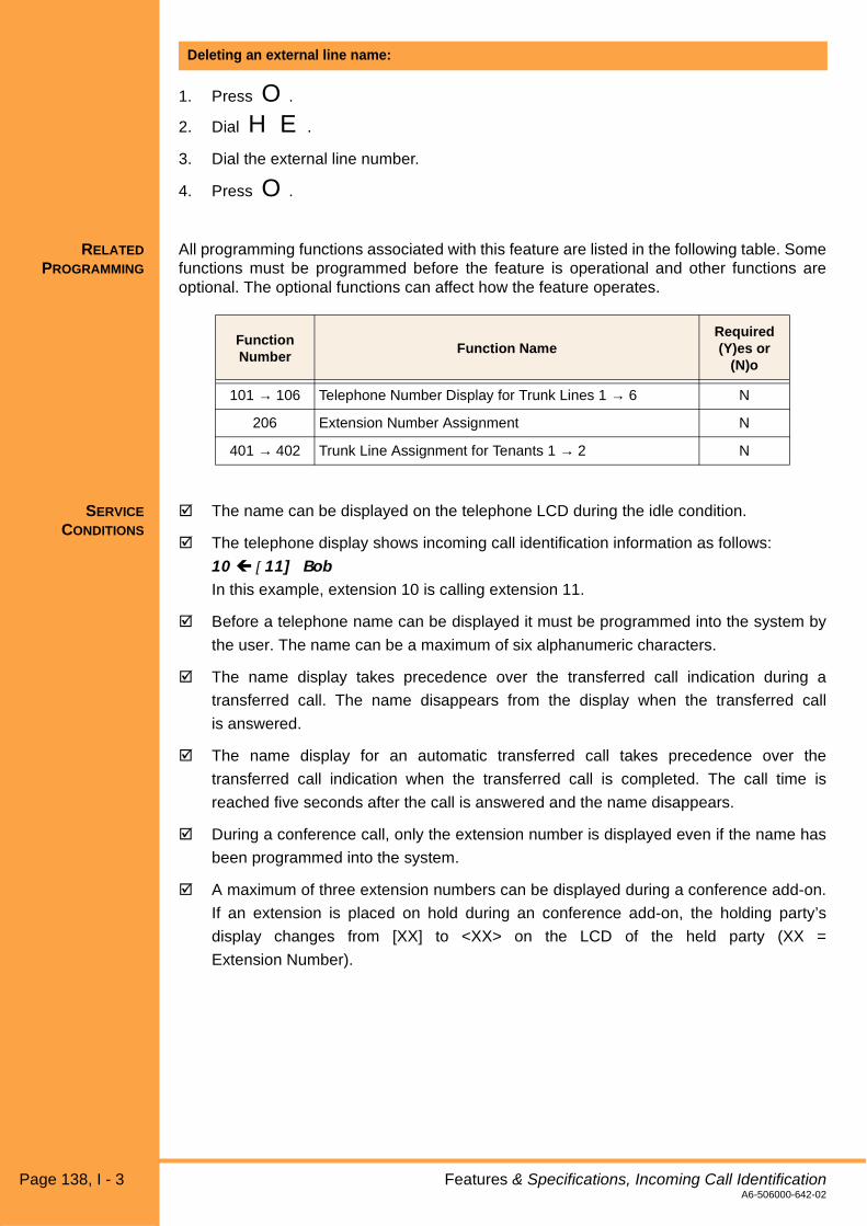
1. Press O.
2. Dial H E.
3. Dial the external line number.
4. Press O.
RELATED
PROGRAMMING
All programming functions associated with this feature are listed in the following table. Somefunctions must be programmed before the feature is operational and other functions areoptional. The optional functions can affect how the feature operates.
SERVICE
CONDITIONS
! The name can be displayed on the telephone LCD during the idle condition.
! The telephone display shows incoming call identification information as follows:
10 # [11] BobIn this example, extension 10 is calling extension 11.
! Before a telephone name can be displayed it must be programmed into the system by
the user. The name can be a maximum of six alphanumeric characters.
! The name display takes precedence over the transferred call indication during a
transferred call. The name disappears from the display when the transferred call
is answered.
! The name display for an automatic transferred call takes precedence over the
transferred call indication when the transferred call is completed. The call time is
reached five seconds after the call is answered and the name disappears.
! During a conference call, only the extension number is displayed even if the name has
been programmed into the system.
! A maximum of three extension numbers can be displayed during a conference add-on.
If an extension is placed on hold during an conference add-on, the holding party’s
display changes from [XX] to <XX> on the LCD of the held party (XX =
Extension Number).
Deleting an external line name:
Function Number
Function NameRequired(Y)es or
(N)o
101 → 106 Telephone Number Display for Trunk Lines 1 → 6 N
206 Extension Number Assignment N
401 → 402 Trunk Line Assignment for Tenants 1 → 2 N
Page 138, I - 3 Features & Specifications, Incoming Call IdentificationA6-506000-642-02

Xen Alpha Release 1.0
I-4 Internal Recall
FEATURE
DESCRIPTION
When hearing a busy tone or error tone, users can capture dialtone for internal calls bypressing a specified key on Multiline telephones or by pressing hookswitch on SingleLine telephones.
STATION
APPLICATION
This feature is available for all Multiline telephones and Single Line telephones.
OPERATION
PROCEDURE
After hearing a busy or error tone, press Q (DTB-type), S(DTU-type), or hookswitch(Single Line telephone). Internal dialtone is provided.
RELATED
PROGRAMMING
All programming functions associated with this feature are listed in the following table. Somefunctions must be programmed before the feature is operational and other functions areoptional. The optional functions can affect how the feature operates.
SERVICE
CONDITIONS
! Internal recall is enabled in the following situations:
• System is waiting for the second digit of an access code to be dialed.
• Busy signal is received when placing an external call.
! If a Single Line telephone has been programmed to seize an external line when going
off-hook, the user must perform a hookflash to access internal dialtone.
Capturing dialtone:
Function Number
Function NameRequired(Y)es or
(N)o
001-9 Single Line Telephone Hookflash Assignment N
Features & Specifications, Internal Recall I - 4, Page 139A6-506000-642-02

This page is intentionally blank.
Page 140, I - 4 Features & SpecificationsA6-506000-642-02

Xen Alpha Release 1.0
I-5 Internal Voice/Tone Signaling
FEATURE
DESCRIPTION
In system programming, internal calls can be assigned to signal an incoming call by eitherringing or voice announcement. The caller can override the system setting for individualcalls by dialling A(access code).
STATION
APPLICATION
This feature is available for all Multiline telephones.
OPERATION
PROCEDURE
1. Lift the handset.
2. When you hear internal dialtone, dial the desired extension number.
3. When you hear the tone, voice announce the call or dial A to provide ringing.
4. The called party can reply handsfree if the call is voice announced. If the call provides
ringing, the called party answers by lifting the handset or by pressing N.
1. Lift the handset.
2. When you hear internal dialtone, dial the desired extension number.
3. The called party’s telephone rings. If you wish to voice announce the call, dial A.
4. The called party can reply handsfree if the call is voice announced. If the call provides
ringing, the called party answers by lifting the handset or by pressing N.
RELATED
PROGRAMMING
All programming functions associated with this feature are listed in the following table. Somefunctions must be programmed before the feature is operational and other functions areoptional. The optional functions can affect how the feature operates.
Making a call when the system is programmed for voice/tone signaling:
Making a call when the system is programmed for tone/voice signaling:
Function Number
Function NameRequired(Y)es or
(N)o
001-1 Internal Call Notification Y
Features & Specifications, Internal Voice/Tone Signaling I - 5, Page 141A6-506000-642-02

SERVICE
CONDITIONS
! Users can toggle between voice/tone by dialling Awhile a call is in progress.
! A Single Line telephone can be used to make voice announcements to Multiline
telephone users.
! A one-touch key can be programmed to switch between voice and tone. A one-touch key
can be programmed to dial the desired extension number and the access code ( A).
! Voice or tone signaling is assigned system-wide using system programming.
! Voice announcement is the system default setting.
! The telephone microphone must be activated for handsfree answer when telephone
receives a voice announced call.
! Users cannot voice announce to Single Line telephones.
! Switching between voice announcement and tone signaling is disabled when calling a
Single Line telephone.
! Tone override is disabled during an incoming voice call.
! The call can only be switched between voice/tone using the Multiline telephone
originating the call.
Page 142, I - 5 Features & Specifications, Internal Voice/Tone SignalingA6-506000-642-02

Xen Alpha Release 1.0
I-6 Internal Zone Paging
FEATURE
DESCRIPTION
Paging is the ability for a key telephone system to broadcast a voice message to a numberof Terminals connected to it. In addition to “All Call Page” and “All Internal Page”, the systemcan be split into two zones; Zone A and zone B and members within a zone can be pagedwithout the other. Terminals can be assigned to zone A and/or zone B or not assigned to anyzone.
STATION
APPLICATION
All stations can initiate an internal page. Only MLT stations are able to receive an internalpage.
OPERATION
PROCEDURE
1. Go off-hook and receive ICM dial tone.
2. Dial the desired Access Code:-
All Internal 70
Zone A 71
Zone B 72
All Int/Ext 77
3. Announce the page.
4. Go on-hook.
1. Go off-hook and receive ICM dial tone.
2. Dial Access Code 74.
3. Speak with the originating station.
4. Go on-hook.
RELATED
PROGRAMMING
To originate an internal zone page from any station:
To answer an internal zone page (Meet-Me):
Function Number
Function NameRequired(Y)es or
(N)o
227 Telephone to Paging Zone A N
228 Telephone to Paging Zone B N
002-3 System settings (2) – Internal All Call Page Receive N
217 Internal Paging Tone N
Features & Specifications, Internal Zone Paging I - 6, Page 143A6-506000-642-02

SERVICE
CONDITIONS
Internal Zone Paging
! There are two zones, A and B. The terminals in these zones are assigned by
programming. A terminal can be in zone A and/or zone B, or not in any zone (can be
reached by all internal page).
! A page can be simultaneously made to zone A and B.
! A busy condition occurs if:
• a page to that zone has already been originated by another station
• an All Call Page has already been originated by another station
• there are no idle stations in the zone
Internal Paging, General
! This section applies also to all types of internal paging.
! Internal paging must be originated from internal dial tone
! The access codes can be stored under an unused line key for One-Touch operation.
! Terminals can be barred from receiving an All Call Page in program.
! Terminals receiving a page can answer the page by entering Code 74 after going off-
hook and receiving ICM dial tone.
! MLT users will not receive an internal page when already engaged on a call. They will
however, receive the page in progress when they become idle.
! An incoming trunk call will ring at a reduced volume while an internal page is in progress
on a DTU-Type telephone. Other MLT telephones will receive visual indication of the
incoming call, but will not receive an audible tone.
! An internal page will not be heard by any MLT who is receiving a DID, DIT or ICM call.
! Single Line Telephone users cannot receive an internal page, but can originate an
internal page or answer an internal page user Meet-Me.
! An internal page automatically times out after 90 seconds.
! A busy condition is generated upon entering an All Call Page access code if:-
• an All Call Page has already been originated by another station
• there are no idle stations
! All call Paging from a 2W or SLT is supported.
! A tone burst is generated as a warning tone whenever a page is initiated (by default).
This tone can be disabled in system programming.
Page 144, I - 6 Features & Specifications, Internal Zone PagingA6-506000-642-02

Xen Alpha Release 1.0
I-7 ISDN Basic Rate Interface
FEATURE
DESCRIPTION
Xen Alpha accepts two ISDN Basic Rate Interfaces in place of 4 analogue trunks. ISDNconnections allow the system to have features such as DID, Malicious Call Trace andCalling line Identification.
STATION
APPLICATION
All stations.
OPERATION
PROCEDURES
SERVICE
CONDITIONS
! DID and Malicious Call Traces are network provided and have to be subscribed from the
service provider before use.
! Two Basic Rate Interfaces give 4 trunks.
! Calls arriving on BRI ISDN lines can be handled as trunk calls or indial calls, depending
upon system programming. When a service number is assigned to a trunk port, that trunk
will ring when a call is made to that number. Alternately, when a service number is
assigned as a station indial number, a call to that number will be treated as an indial call
and will ring directly at the station.
! The system supports Point to Multi-point connections only.
Not applicable.
Features & Specifications, ISDN Basic Rate Interface I - 7, Page 145A6-506000-642-02

This page is intentionally blank.
Page 146, I - 7 Features & SpecificationsA6-506000-642-02

Xen Alpha Release 1.0
I-8 ISDN Malicious Call Trace
FEATURE
DESCRIPTION
Malicious Call Trace in the Australian ISDN is a subscribed service on top of the ISDN basicservice. This allows the user to trace a malicious call during a call. The information from thetrace is printed in the exchange and the customer then contacts the Police for further action.The Police then obtain the information from the Network Service provider. Unlisted andlisted numbers can be traced. This trace is on a call by call basis and controlled by the user.
STATION
APPLICATION
All stations.
OPERATION
PROCEDURES
1. Press Access Code FNC-91, message on LCD indicating if successful or not.
2. Contact Police about the call and when the call occurred.
SERVICE
CONDITIONS
! This feature only works on the ISDN interface and must be subscribed to from the
Network service provider. The MCT feature must be enabled in the KTS as well.
! Calling from the KTS cannot activate this service.
! Malicious call trace is not possible if performed after the caller terminates the call.
! Malicious call trace can trace unlisted/unpresented numbers.
! Only the Police can access the information for a Malicious Call via the service provider.
During conversation on a Malicious ISDN trunk call:
Features & Specifications, ISDN Malicious Call Trace I - 8, Page 147A6-506000-642-02

This page is intentionally blank.
Page 148, I - 8 Features & SpecificationsA6-506000-642-02

Xen Alpha Release 1.0
I-9 I-Use Indication
FEATURE
DESCRIPTION
This feature provides indications about the line that is in use by illuminating the green LEDassociated with the line key. Busy lines are illuminated in red, this allows the user to quicklyidentify those lines that are in use.
STATION
APPLICATION
This feature is available for all Multiline telephones.
OPERATION
PROCEDURE
RELATED
PROGRAMMING
All programming functions associated with this feature are listed in the following table. Somefunctions must be programmed before the feature is operational and other functions areoptional. The optional functions can affect how the feature operates.
SERVICE
CONDITIONS
! If an external call is transferred to an extension that is a member of another tenant group,
LED indication is provided. For all other types of calls, no LED indication is provided to
extensions that are members of a different tenant group.
! A solid green LED indicates the I-Use condition on the telephone with a call in progress.
Other telephones in the system display a red LED to indicate the line is in use.
! I-Hold condition is indicated by a flashing green LED.
Not applicable.
Function Number
Function NameRequired(Y)es or
(N)o
206 Extension Number Assignment N
209 Outgoing Call Priority Mode N
301 → 306 Day Ringing for Trunk Lines 1 → 6 N
311 → 316 Night Ringing for Trunk Lines 1 → 6 N
401 → 402 Trunk to Tenant Assignment Tenants 1 → 2 N
Features & Specifications, I-Use Indication I - 9, Page 149A6-506000-642-02

This page is intentionally blank.
Page 150, I - 9 Features & SpecificationsA6-506000-642-02
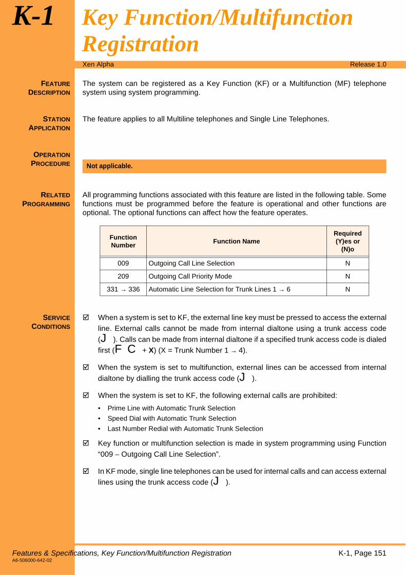
Xen Alpha Release 1.0
K-1 Key Function/Multifunction Registration
FEATURE
DESCRIPTION
The system can be registered as a Key Function (KF) or a Multifunction (MF) telephonesystem using system programming.
STATION
APPLICATION
The feature applies to all Multiline telephones and Single Line Telephones.
OPERATION
PROCEDURE
RELATED
PROGRAMMING
All programming functions associated with this feature are listed in the following table. Somefunctions must be programmed before the feature is operational and other functions areoptional. The optional functions can affect how the feature operates.
SERVICE
CONDITIONS
! When a system is set to KF, the external line key must be pressed to access the external
line. External calls cannot be made from internal dialtone using a trunk access code
(J). Calls can be made from internal dialtone if a specified trunk access code is dialed
first (FC + X) (X = Trunk Number 1 → 4).
! When the system is set to multifunction, external lines can be accessed from internal
dialtone by dialling the trunk access code (J).
! When the system is set to KF, the following external calls are prohibited:
• Prime Line with Automatic Trunk Selection
• Speed Dial with Automatic Trunk Selection
• Last Number Redial with Automatic Trunk Selection
! Key function or multifunction selection is made in system programming using Function
“009 – Outgoing Call Line Selection”.
! In KF mode, single line telephones can be used for internal calls and can access external
lines using the trunk access code (J).
Not applicable.
Function Number
Function NameRequired(Y)es or
(N)o
009 Outgoing Call Line Selection N
209 Outgoing Call Priority Mode N
331 → 336 Automatic Line Selection for Trunk Lines 1 → 6 N
Features & Specifications, Key Function/Multifunction Registration K-1, Page 151A6-506000-642-02

This page is intentionally blank.
Page 152, K-1 Features & SpecificationsA6-506000-642-02

Xen Alpha Release 1.0
M-1 Manual Line Seizure
FEATURE
DESCRIPTION
An outside line can be accessed by pressing a line key.
STATION
APPLICATION
This feature is available for all Multiline telephones.
OPERATION
PROCEDURE
1. Press V (external line key). The N LED lights and dialtone is heard.
2. Remain on the speakerphone or lift the handset.
SERVICE
CONDITIONS
! An error is displayed in the telephone LCD when the user presses a line key that cannot
seize an external line (e.g., the external line is a member of another tenant).
! The line key LED on the telephone that seizes the line lights green, all other telephone
LEDs light red.
! When manual line seizure is attempted by more than one telephone user
simultaneously, the line key LED on the first telephone to select the external line lights
green. The other telephones receive the message “IN USE” in the telephone LCD.
Manually accessing an outside line:
Features & Specifications, Manual Line Seizure M-1, Page 153A6-506000-642-02

This page is intentionally blank.
Page 154, M-1 Features & SpecificationsA6-506000-642-02

Xen Alpha Release 1.0
M-2 Manual Pause
FEATURE
DESCRIPTION
This feature allows users to insert a pause while dialling a telephone number. The pausecan also be programmed on a one-touch/feature access key or can be inserted by diallingan access code.
STATION
APPLICATION
This feature it available for all Multiline telephones.
OPERATION
PROCEDURE
1. Lift the handset or press N.
2. Press O.
3. Dial D. The pause is inserted.
1. Press O.
2. Press T (Q for DTU-type telephones).
3. Press V (line key to be programmed as the one-touch/feature access key).
4. Press L D.
5. Press O.
SERVICE
CONDITIONS
! Call restriction is not checked for a pause.
! Manual pauses are stored in the last number redial memory location and can be stored
in speed dial memory locations.
Inserting a pause:
Assigning a one-touch key to manually insert a pause:
Features & Specifications, Manual Pause M-2, Page 155A6-506000-642-02

This page is intentionally blank.
Page 156, M-2 Features & SpecificationsA6-506000-642-02

Xen Alpha Release 1.0
M-3 Microphone Control
FEATURE
DESCRIPTION
The microphone can be turned on and off and the on/off status is indicated on the Multilinetelephone. A one-touch key can be programmed for microphone control or an access codecan be dialed to mute the microphone for privacy during incoming voice announced callsand during calls that use the built-in speaker phone.
STATION
APPLICATION
This feature is available for all Multiline telephones.
OPERATION
PROCEDURE
1. Press the one-touch key programmed to control the microphone. The microphonetoggles on and off.
1. Press O A. The microphone toggles on and off.
RELATED
PROGRAMMING
All programming functions associated with this feature are listed in the following table. Somefunctions must be programmed before the feature is operational and other functions areoptional. The optional functions can affect how the feature operates.
SERVICE
CONDITIONS
! When the system is initially powered up, all microphones are turned on. If the systemloses power or is turned off and then on, the microphones retain the on/off status thatwas set before the power loss.
! When calling another telephone within the system, the user’s voice is heard through thespeaker at the called telephone.
! When the microphone is on, the MIC LED lights red. When the microphone is off, theMIC LED is off.
! A telephone that is disabled for handsfree speakerphone operation can still use thespeakerphone for internal voice announcements.
! If the handsfree option is not turned on when N is pressed, the speakerphoneoperation will not function.
Using a one-touch key to turn the microphone on/off:
Using an access code to turn the microphone on/off:
Function Number
Function NameRequired(Y)es or
(N)o
216 Handsfree Assignment N
Features & Specifications, Microphone Control M-3, Page 157A6-506000-642-02

This page is intentionally blank.
Page 158, M-3 Features & SpecificationsA6-506000-642-02

Xen Alpha Release 1.0
M-4 Music on Hold
FEATURE
DESCRIPTION
Music can be provided to caller’s on hold using the system’s internal music source or byconnecting an external music source (user-provided) such as a radio, tape player, orcompact disc.
STATION
APPLICAITON
This feature is available for all Multiline telephones and Single Line telephones.
OPERATION
PROCEDURE
RELATED
PROGRAMMING
All programming functions associated with this feature are listed in the following table. Somefunctions must be programmed before the feature is operational and other functions areoptional. The optional functions can affect how the feature operates.
SERVICE
CONDITIONS
! The external music on hold and background music share the same input source on
the KSU.
! Music on hold can be generated in internal an external calls that are placed on hold.
! The music on hold source can be selected from the internal or external music on hold
source, which is connected to external hold tone/background music on the KSU.
! When using external music on hold, the music source (e.g., tape deck, radio, CD) must
be connected to the system. Music is not generated if the external music on hold is
specified but the external music source has not been connected.
! The internal music on hold source provides a selection of two tones:
- “Je Te Veus”
- Minuet
Not applicable.
Function Number
Function NameRequired(Y)es or
(N)o
002-1 Music Source for Music on Hold N
012 Music on Hold Melody N
Features & Specifications, Music on Hold M-4, Page 159A6-506000-642-02

This page is intentionally blank.
Page 160, M-4 Features & SpecificationsA6-506000-642-02

Xen Alpha Release 1.0
N-1 Nesting Dial
FEATURE
DESCRIPTION
This feature allows speed dial buffer numbers (either system or individual) to be nested orchained into another buffer, allowing numbers to be dialled consecutively by simply pressingone button.
STATION
APPLICATION
This feature is available for all Multiline telephones and Single Line telephones. Note thatthe Single Line telephones cannot be used to program nesting dial, but they can use thenesting dial feature.
OPERATION
PROCEDURE
1. Press O.
2. Press T.
3. Dial the speed dial memory location number where the other speed dial memorylocation numbers will be stored (B J → I I or J J J → A I I).
4. Press R.
5. Dial the speed dial memory location number(s) that will be nested or chain dialled (BJ → I I or J J J → A I I). (Repeat steps 4 and 5 for eachmemory location number to be nested.)
6. Press U and enter a name if desired. (Refer to Character Registration, Page 65 forinstructions about entering names.)
7. Press O.
1. Press T.
2. Dial the speed dial memory location number where the other memory location numbersthat will be consecutively dialled are stored (B J → I I or J J J → A I I).
The system automatically dials the numbers that were stored in each of thememory locations.
Programming nested dialling
Using nested dialling:
Features & Specifications, Nesting Dial N-1, Page 161A6-506000-642-02

1. Press P.
2. Press T.
3. Dial the speed dial buffer number where the other buffers numbers (B J → I I or J J J → A I I) that will be consecutively dialledare stored.
The system displays the buffers numbers that were stored in the nested dialling buffer.
4. Press O to scroll to the next page if necessary.
1. Press O.
2. Press S.
3. Dial the speed dial buffer number where the other buffers numbers (B J → I I or J J J → A I I) that will be consecutively dialledare stored .
4. Press O.
1. Press O.
2. Press S.
3. Dial the speed dial buffer number where the other buffers numbers (B J → I I or J J J → A I I) that will be consecutively dialledare stored.
4. Press U.
5. Press O.
RELATED
PROGRAMMING
All programming functions associated with this feature are listed in the following table. Somefunctions must be programmed before the feature is operational and other functions areoptional. The optional functions can affect how the feature operates.
Confirming the buffers stored in a nested dialling memory location:
Deleting a nested speed dial memory location:
Deleting a speed dial memory location and associated name:
Function Number
Function NameRequired(Y)es or
(N)o
001-2 Speed Dial Assignment N
Page 162, N-1 Features & Specifications, Nesting DialA6-506000-642-02
SERVICE
CONDITIONS
! A maximum of five speed dial memories can be nested. If a sixth speed dial memory
location is attempted to be nested, “ERROR” is displayed in the telephone LCD.
! A speed dial memory cannot be nested into itself.
! A speed dial memory with nested numbers cannot be nested in another speed dial
memory location.
! Station speed dial memory locations cannot be nested into system speed dial
memory locations.
! If a call is originated using speed dialling and the memory location is empty, the following
message is displayed in the telephone LCD: XX: Empty (XX = Memory
Location Number).
! If a call is originated with a speed dial number that has more than three nested speed
dial memory locations, only the first three memory locations are displayed in the
telephone LCD.
! If a call is originated with a speed dial number that has a “name” associated with it, the
“name “ is displayed in the telephone LCD. The clock display is restored when the
external party answers the call.
! A maximum of 24 digits can be programmed in a speed dial memory. A nesting dial is
counted as three digits in the 80 system speed dial mode and four digits in the 200
system speed dial mode.
! Speed dialling can be used after manually dialling the number for Multiline telephones.
This cannot be done for Single Line telephones.
! Nested speed dial numbers cannot be programmed from a Single Line telephone.
However, speed dial calls can be made from a Single Line telephone.
Features & Specifications, Nesting Dial N-1, Page 163A6-506000-642-02

This page is intentionally blank.
Page 164, N-1 Features & SpecificationsA6-506000-642-02

Xen Alpha Release 1.0
N-2 Night Mode
FEATURE
DESCRIPTION
All telephones in the system can be placed into or out of night mode. This provides changesin the ringing assignment for central office and PBX lines and direct inward termination (DIT)assignments. This mode is set on a system-wide basis.
STATION
APPLICATION
This feature is available for all Multiline telephones.
! Refer to Automatic Day/Night Mode Switching, Page 15 for instructions forautomatically switching between day/night modes.
OPEATION
PROCEDURE
1. Press O while the telephone is in the idle condition.
2. Dial H J.
3. Press O.
1. Press O while the telephone is in the idle condition.
2. Press T.
3. Press V (the one-touch key to be assigned for night mode).
4. Dial L H J.
5. Press U to enter an associated name. (Refer to Character Registration, Page 65 forinstructions about assigning a name.)
6. Press O.
Manually setting night mode:
Assigning a one-touch key to set night mode:
Features & Specifications, Night Mode N-2, Page 165A6-506000-642-02

RELATED
PROGRAMMING
All programming functions associated with this feature are listed in the following table. Somefunctions must be programmed before the feature is operational and other functions areoptional. The optional functions can affect how the feature operates.
SERVICE
CONDITIONS
! Ringing is not generated for incoming calls from another tenant group regardless of
the settings.
! Multiline telephones without ringing remain silent. However, the external line key LED
flashes red.
! Ringing can be assigned to each Multiline and Single Line telephone for both day mode
and night mode.
! All telephones can be assigned to ring on incoming calls on all lines for both night mode
and day mode.
! When the system switches to night mode, the telephone display switches to:
• Night (DTB-type telephones)
• llll (DTU-type telephones - displayed on the left side of the clock)
! Night mode toggles on and off when the manual switching operation is performed.
Function Number
Function NameRequired(Y)es or
(N)o
124 External Ringing for Day Mode (Trunk Based) N
125 External Ringing for Night Mode (Trunk Based) N
140 →145Direct Calling for Day Mode on Trunk Lines 1 → 6 (DIT Assignment)
N
146 →151Direct Calling for Night Mode on Trunk Lines 1 → 6 (DIT Assignment)
N
148 Direct Calling Answer Delay Time (DIT Answer Delay) N
149 Direct Calling Delay for Night Mode (DIT Answer Delay) N
210 → 211 Doorphones 1 → 2 Tone for Day Mode N
213 → 214 Doorphones 1 → 2 Tone for Night Mode N
301 → 306 Day Ringing for Trunk Lines 1 → 6 Y
311 → 316 Night Ringing for Trunk Lines 1 → 6 Y
225 External Ringing for Day Mode (Station Based) N
226 External Ringing for Night Mode (Station Based) N
Page 166, N-2 Features & Specifications, Night ModeA6-506000-642-02

! Day/Night mode switching affects the following functions:
• Incoming Call Identification (assigned using Functions “301 → 306 – Day Ringing for TrunkLines 1 → 6 and 311 → 316 – Night Ringing for Trunk Lines 1 → 6”)
• External Ring Control (assigned using Functions “124 – External Ringing for Day Mode, 125– External Ringing for Night Mode, 225 - External Ringing for Day Mode (Station Based)and 226 - External Ringing for Night Mode (Station Based)”)
• Doorphone Ring Assignment (assigned using Functions “210 → 211 – Doorphones 1 → 2for Day Mode and 213 → 214 – Doorphones 1 → 2 for Night Mode”)
• Direct Calling Assignment (DIT) (assigned using Functions “140 → 145 - Direct Calling forDay Mode on Trunk Lines 1 → 6, and 146 → 151 - Direct Calling for Night Mode on TrunkLines 1 → 6”).
! When exiting Programming Mode, the Night Mode state of the system will be set
according to Function Numbers 041 → 018, automatic night mode switching
assignments. By default, these are assigned to ‘continuous day mode’ causing a
manually set night mode to be cancelled.
Features & Specifications, Night Mode N-2, Page 167A6-506000-642-02

This page is intentionally blank.
Page 168, N-2 Features & SpecificationsA6-506000-642-02
Xen Alpha Release 1.0
O-1 Off-Hook Ringing
FEATURE
DESCRIPTION
If a user is currently on a call and receives another external call, off-hook ringing is providedto the telephone’s external speaker. Off-hook Ringing is at a lower volume than normal on-hook ringing.
STATION
APPLICATION
This feature is available for all Multiline telephones.
OPERATION
PROCEDURE
RELATED
PROGRAMMING
All programming functions associated with this feature are listed in the following table. Somefunctions must be programmed before the feature is operational and other functions areoptional. The optional functions can affect how the feature operates.
SERVICE
CONDITIONS
! Off-hook ringng is only enabled for external lines that have incoming external ringing
specified.
! Off-hook ringing volume can be adjusted.
! A multiline telephone that is using the speakerphone or is set for do not disturb does not
receive off-hook ringing tone.
! A doorphone can generate off-hook ringing tone.
! Off-hook ringing can be generated during a call where the headset is used (headset is
only available for Xen System telephones).
! On DTB-type and ETW-type Multiline telephones, off-hook ringing is not heard while the
telephones are operating in handsfree mode.
Not applicable.
Function Number
Function NameRequired(Y)es or
(N)o
202 Off-Hook Ringing Tone N
Features & Specifications, Off-Hook Ringing O-1, Page 169A6-506000-642-02

This page is intentionally blank.
Page 170, O-1 Features & SpecificationsA6-506000-642-02

Xen Alpha Release 1.0
O-2 One-Touch/Feature Access Keys – User Programmable
FEATURE
DESCRIPTION
Multiline telephone users can press a single key that has been programmed for functionssuch as speed dialling, extension numbers, access codes, etc. By using the one-touch keythe user does not need to go off-hook, they simply press the programmed key and thesystem seizes a line and dials the number.
STATION
APPLICATION
This feature is available for all Multiline telephones.
OPERATING
PROCEDURE
1. Press O while the telephone is in the idle condition.
2. Press T (DTB-type telephones) or Q (DTU-type telephones).
3. Press V (one-touch/feature access key).
Note: This must be line key that not being used to seize an external line or hasalready been assigned as a one-touch/feature access key.
4. Enter the appropriate “dial operation code” (i.e., K, L, JA, or B). These dialoperation codes indicate to the system which operation is being stored under the one-touch key. For example, if ✱ is entered then the system expects a CO/PBX number of24 digits (maximum) to be entered. The following tables list each dial operation code, adescription of the operation, the maximum number of digits that can be entered for thenumber being stored, and the valid number/special “codes” that can be stored for eachnumber.
Programming a one-touch/feature access key:
Dial Operation
Code
Dial Operation Description
Maximum Digits
Valid Entry Keys
✱CO/PBX Telephone Number
24
0 → 9, ✱, #
T or Q = Pause
QorS= Hookflash
R= Nesting Dial
#Feature Access Number
160 → 9, ✱, #
0 Speed Dial Number 15 0 → 9, ✱, #
1 Extension Number 16 0 → 9, ✱, #
2 Feature Number 2 0 → 9, ✱, #
Features & Specifications, One-Touch/Feature Access Keys – User Programmable O-2, Page 171A6-506000-642-02

5. Enter the appropriate telephone number, speed dial memory location number,extension number, special dial number, or feature access code.
6. Press U and enter the associated “name” (alphabetic characters). (Refer toCharacter Registration, Page 65 for instructions about entering alphanumericcharacters.)
7. Press O.
1. Press V (CO/PBX line key to seize an external line).
2. Press V (one-touch /feature access key where the speed dial number is stored).
3. Remain on the speakerphone or lift the handset to talk when the called party answers.
- OR -
1. Press O.
2. Press V (one-touch/feature access key). The stored data is displayed in thetelephone LCD.
3. Press V (CO/PBX line key to seize an external line).
4. Remain on the speakerphone or lift the handset to talk when the called party answers.
1. Press O.
1. Press V (one-touch/feature access where the data is stored). If data has been storedfor the one-touch/feature access key it is displayed in the telephone LCD. If no data hasbeen stored, “ERROR” is displayed in the telephone LCD.
1. Press O while the telephone is in the idle condition.
2. Press T (DTB-type telephones) or Q (DTU-type telephones).
3. Press V (one-touch/feature access key).
4. Press O.
1. Press O while the telephone is in the idle condition.
2. Press T (DTB-type telephones) or Q (DTU-type telephones).
3. Press V (one-touch/feature access key).
4. Press U to delete the alphanumeric “name” associated with the one-touch/featureaccess key.
5. Press O.
Using the one-touch/feature access key for speed dialling:
Confirming data stored under a one-touch/feature access key:
Deleting data stored under a one-touch/feature access key:
Deleting the “name” associated with a one-touch/feature access key:
Page 172, O-2 One-Touch/Feature Access Keys – User Programmable ,Features & SpecificationsA6-506000-642-02

RELATED
PROGRAMMING
All programming functions associated with this feature are listed in the following table.Some functions must be programmed before the feature is operational and other functionsare optional. The optional functions can affect how the feature operates.
SERVICE
CONDITIONS
! Any unused line keys can be assigned as one-touch/feature access keys.
! When deleting one-touch/feature access key information, the dialling information and
the associated “name” (if assigned) must be deleted in separate operations.
! If CO and PBX lines are assigned, the call cannot be completed unless the PBX access
code is stored under the one-touch/feature access key as part of the dialling string.
! If duplicate information is stored under more than one one-touch/feature access key,
the information that was previously stored is erased and the current information
is stored.
! If the number of speed dial memory locations is changed using “001-2 – Speed Dial
Assignment”, all data that is stored under one-touch/feature access keys is deleted.
Function Number
Function NameRequired(Y)es or
(N)o
001-2 Speed Dial Assignment N
001-7 One-Touch Key Direct Access for Outgoing Calls N
001-8 One-Touch Key Duplication Assignment N
009 Outgoing Call Line Selection N
107 Trunk Line Type N
109 Trunk Line Dialling Type N
Features & Specifications, One-Touch/Feature Access Keys – User Programmable O-2, Page 173A6-506000-642-02

This page is intentionally blank.
Page 174, O-2 Features & SpecificationsA6-506000-642-02

Xen Alpha Release 1.0
P-1 PC Programming
FEATURE
DESCRIPTION
Users can program the key system using a PC. A PC is connected to the key system usingan RS-232C cable which allows the system parameters to be downloaded to the PC andthen modified. Once modified, the system parameters are then uploaded to the key system.
An MIF-B13 ETU must be installed in the system for this feature to operate.
The minimum requirements for the PC to run this program include:
" 100 MHz Pentium processor
" 16 MB RAM
" 10 MB hard disk space
" 640 x 480 monitor resolution
" Window 95/98
" Internet Explorer 4.1
" Netscape Communicator 4.7
The recommended requirements for running PC Programming include:
" 166 MHz Pentium processor
" 64 MB RAM
" 10 MB hard disk space
" 1024 x 768 monitor resolution
" Windows 95/98
OPERATING
PROCEDURES
1. Press O.
2. Dial I F.
3. Press O.
SERVICE
CONDITIONS
! The PC port is used for both SMDR print output and PC programming. The system must
be in PC programming mode before connecting a PC to the system. This is
accomplished by dialling O I F from either extension 10 or 11. (Note that this
access code is used to toggle between the SMDR print output mode and PC
programming mode.) The mode is displayed in the telephone LCD for five seconds
allowing the user to verify that the desired mode has been properly set.
Refer to PC Programming, Page 175 for operational instructions.
To Switch Between PC Programming and SMDR Output Mode for MIF ETU:
Features & Specifications, PC Programming P-1, Page 175A6-506000-642-02

! When system data is uploaded from the PC to the KSU, the KSU is updated with the
data from PC programming. During the upload process, data is temporarily stored in a
“working” memory area if any of the telephones are in-use. Once the system is idle, the
data is updated in system memory.
! The baud rate between the MIF-B13 ETU and the PC is fixed at 19,200 bps and the
Start/Stop bit is set to 1.
! All user programmable assignments such as one-touch keys and speed dialling can also
be assigned using PC programming.
Page 176, P-1 PC Programming, Features & SpecificationsA6-506000-642-02

Xen Alpha Release 1.0
P-2 Power Failure Transfer
FEATURE
DESCRIPTION
Power Failure Transfer ensures that a customer has access to the telephone company’scentral office network during a power outage. When system power is lost and powersupplied by the battery backup has expired, analogue trunks 1 and 2 (built into themainboard) are automatically switched to the two analogue telephones connected to theFAX/PFT ports of the KSU.
STATION
APPLICATION
This feature is available for use with single line telephones connected to the FAX/PFT ports.
OPERATING
PROCEDURES
SERVICE
CONDITIONS
! During a power outage, calls can be made from and received by the single line telephone
connected to the FAX/PFT ports of the KSU.
! For the power fail telephones to operate, analogue PSTN lines must be connected to
Trunk Ports 1 and/or 2, which are built-in to the mainboard.
FAX/PFT 1 → CO1
FAX/PFT 2 → CO2
! The signalling method used by the telephone (DTMF or Decadic) must match that
supported by the trunk it is to be connected to during a power fail condition.
! The FAX/PFT ports can be used during normal system operation to directly access
Trunk Ports 1 and 2, for use by analogue devices such as fax machines, modems, etc.
Connection in this way does not require a SLI(2)-B13 ETU or other analogue port
adapter. Busy trunk status is provided to other telephones in the system when these
devices are in use.
Not applicable.
Features & Specifications, Power Failure Transfer P-2, Page 177A6-506000-642-02

This page is intentionally blank.
Page 178, P-2 Features & SpecificationsA6-506000-642-02

Xen Alpha Release 1.0
P-3 Preset Dialling
FEATURE
DESCRIPTION
This feature allows users to dial a telephone number before actually going off-hook. Thenumber is displayed in the telephone LCD allowing the user to verify the number beforeactually going off-hook. The number is dialed once the user goes off-hook.
STATION
APPLICATION
This feature is available for all Multiline telephones.
OPERATING
PROCEDURES
1. Before going off-hook, dial the telephone number.
2. Go off-hook by lifting the handset or pressing V (line key).
RELATED
PROGRAMMING
All programming functions associated with this feature are listed in the following table. Somefunctions must be programmed before the feature is operational and other functions areoptional. The optional functions can affect how the feature operates.
SERVICE
CONDITIONS
! A maximum of 24 digits can be entered. If the user attempts to enter more than 24 digits,
“ERROR” is displayed in the telephone LCD and preset dialling is canceled.
! If function “209 – Outgoing Call Priority Mode” is set to Internal Line preference, preset
dialling is only available when a CO line key is pressed; it is not available by lifting
the handset.
! Call Restriction is performed after the external line is seized.
! After the digit display timer expires (10 seconds), preset dialling is canceled if the user
does not press an available CO line key or lifts the handset.
Dialling:
Function Number
Function NameRequired(Y)es or
(N)o
209 Outgoing Call Priority Mode N
Features & Specifications, Preset Dialling P-3, Page 179A6-506000-642-02

This page is intentionally blank.
Page 180, P-3 Features & SpecificationsA6-506000-642-02

Xen Alpha Release 1.0
P-4 Prime Line Assignment
FEATURE
DESCRIPTION
Prime Line Assignment allows a user to go off-hook and make an external call from a trunkline without pressing a line key. The system is programmed to automatically select aspecified trunk line when the user goes off-hook. Internal calls are made by pressing Nwhich accesses internal dialtone.
STATION
APPLICATION
This feature is available for all Multiline telephones and single line telephones.
OPERATING
PROCEDURES
1. Lift the handset. The outside line is automatically seized.
1. Press N to access internal dialtone.
2. Remain on the speakerphone or lift the handset and dial the desired extension number.
RELATED
PROGRAMMING
All programming functions associated with this feature are listed in the following table. Somefunctions must be programmed before the feature is operational and other functions areoptional. The optional functions can affect how the feature operates.
SERVICE
CONDITIONS
! At default all telephones are set to seize the first available external line.
! If a telephone is assigned to seize an external line, preset dialling is performed after the
user dials the number and then lifts the handset.
Making an external call:
Making an internal call:
Function Number
Function NameRequired(Y)es or
(N)o
209 Outgoing Call Priority Mode N
331 → 336 Automatic Line Selection for Trunk Lines 1 → 6 N
Features & Specifications, Prime Line Assignment P-4, Page 181A6-506000-642-02
! If an external line is assigned for automatic answering (using Functions “341 → 346 to
Automatic Answering using Trunks 1 → 6”), external ringing calls are answered when the
handset is lifted. If the external line is a transferred call, that external line is answered
when the handset is lifted.
! The external line is seized after the handset is lifted and the external line key is pressed.
! If the handset is lifted during trunk queuing, the queued external line is seized.
! A single line telephone that has been assigned to seize an external line accesses
internal dialtone by pressing hookflash.
Page 182, P-4 Prime Line Assignment, Features & SpecificationsA6-506000-642-02

Xen Alpha Release 1.0
P-5 Privacy On All Calls
FEATURE
DESCRIPTION
The system provides complete privacy on all calls. No other telephone user can enteranother’s conversation unless that user permits them to enter the conversation by releasingprivacy or by adding them to a conference. The Barge-In feature, if enabled, overridesprivacy on all calls and allows the barge-in user to enter the conversation.
STATION
APPLICAITON
This feature is available for all Multiline telephones and single line telephones.
OPERATING
PROCEDURES
Press O G while engaged on a trunk call to release privacy.
Lift the handset and press the line key of the call where privacy has been released.
RELATED
PROGRAMMING
All programming functions associated with this feature are listed in the following table. Somefunctions must be programmed before the feature is operational and other functions areoptional. The optional functions can affect how the feature operates.
Releasing privacy:
Connecting to a call that has been released;
Function Number
Function NameRequired(Y)es or
(N)o
002-8 Private Call Y
Features & Specifications, Privacy On All Calls P-5, Page 183A6-506000-642-02

SERVICE
CONDITIONS
! Privacy release cannot occur while dialling. After the called party answers or any
incoming call is answered, privacy can be released.
! Privacy release cannot occur if an add-on conference is in progress.
! Privacy release cannot be performed if all conference circuits are in use. When all
conference circuits are busy, the P LED lights red.
! Only one telephone user can interrupt another’s conversation using privacy release.
! A maximum of two external lines can have privacy released.
! Privacy release can only occur for external lines within the same tenant group. If a call
is transferred to another tenant group, privacy cannot be released.
! Privacy on all calls is the default setting when the system is initially installed.
! The Barge-In feature can be used to access a telephone line that does not have privacy
released. If Barge-In is enabled in system programming, it overrides the privacy
assignment. [Refer to Barge-In (Interrupting an External Call), Page 29.]
! Privacy on all calls a can be released by individual users by pressing O G while on
an external call. If O G are pressed again, privacy release is canceled.
! Privacy release is not available for single line telephones.
! Privacy for all calls is restored after the external line that has released privacy hangs up
or presses hookflash.
! LCD indication for privacy release is the same as the display for an add-on conference
on an external line.
! The P LED flashes red on the telephone where privacy is released and lights solid red
on the P LED on the telephone that picks up the line.
! A single line telephone can access an external line that has privacy released by dialling
F C and the external line number.
Page 184, P-5 Privacy On All Calls, Features & SpecificationsA6-506000-642-02

Xen Alpha Release 1.0
P-6 Programmable Pause for Speed Dial
FEATURE
DESCRIPTION
Users can insert a pause when programming speed dial numbers using this feature. Thepause allows a short delay before accessing an external line.
STATION
APPLICATION
This feature is available for all Multiline telephones.
OPERATING
PROCEDURES
While entering a speed dial number, press T (DTB-type telephones) or Q (DTU-typetelephones). A pause is inserted between digits.
SERVICE
CONDITIONS
! A pause can be programmed as the first digit of a dialling string.
! Pauses cannot be inserted using a single line telephone.
! Pauses can be entered when speed dial number are assigned using PC programming.
! A single line telephone can use speed dial numbers that include pauses.
! Pauses can be inserted between digits. Consecutive pauses can also be inserted into a
dialling string.
! A pause is counted as one digit (speed dial numbers are a maximum or 24 digits).
! One pause is equivalent to three seconds (fixed).
Programming a pause:
Features & Specifications, Programmable Pause for Speed Dial P-6, Page 185A6-506000-642-02

This page is intentionally blank.
Page 186, P-6 Features & SpecificationsA6-506000-642-02

Xen Alpha Release 1.0
P-7 Programming from Multiline Telephone
FEATURE
DESCRIPTION
The system can be programmed using a multiline telephone. It is necessary to use atelephone with an LCD to view the programmable options. Only ports 1 and 2 (normallyassigned to extensions 10 and 11) are used for telephone programming.
STATION
APPLICATION
This feature is applicable for all display Multiline telephones.
OPERATING
PROCEDURES
SERVICE
CONDITIONS
! “PROGRAMMING DATA” is displayed in the telephone LCD while system data is
being updated after exiting Programming Mode.
! Only one telephone can be in programming mode at a time.
! System data can be programmed while the system is operational.
! Background music and room monitoring are disabled when the system is being
programmed.
! Upon exiting Programming Mode, Night Mode is set according to the programming of
function numbers 014 → 018.
Refer to Telephone Programming, Page 1.
Features & Specifications, Programming from Multiline Telephone P-7, Page 187A6-506000-642-02

This page is intentionally blank.
Page 188, P-7 Features & SpecificationsA6-506000-642-02

Xen Alpha Release 1.0
R-1 Resident System Program
FEATURE
DESCRIPTION
When power is supplied to the system, the system scans the hardware configuration andassigns default values. This allows for plug-and-play operation of the system. Onceoperational, the system can be customized for individual customers.
OPERATING
PROCEDURES
RELATTED
PROGRAMMING
All programming functions associated with this feature are listed in the following table. Somefunctions must be programmed before the feature is operational and other functions areoptional. The optional functions can affect how the feature operates.
SERVICE
CONDITIONS
! At default, external line keys 1 → 4 (depending on hardware configuration) are assigned
DTMF (touchtone) signaling.
! At default, without expansion, Line Keys 1 and 2 are assigned as Trunk 1 and 2. Line
Keys 3 to 6 are assigned as one-touch/feature access keys.
! At default, when one trunk card is installed, Line Keys 1 to 4 are assigned as Trunks 1
to 4 and Line Keys 5 and 6 are assigned as one-touch/feature access keys.
! At default, when two trunk cards are installed, Line Keys 1 to 6 are assigned as Trunks
1 to 6.
Not applicable.
Function Number
Function NameRequired(Y)es or
(N)o
109 Trunk Line Dialling Type N
Features & Specifications, Resident System Program R-1, Page 189A6-506000-642-02

This page is intentionally blank.
Page 190, R-1 Features & SpecificationsA6-506000-642-02

Xen Alpha Release 1.0
R-2 Ringing Line Preference
FEATURE
DESCRIPTION
When using ringing line preference, the user can answer any ringing line on their multilinetelephones by lifting the handset or pressing N (it is not necessary to press the linekey first).
STATION
APPLICATION
This feature is available for all Multiline telephones and single line telephones.
OPERATING
PROCEDURES
1. Lift the handset and talk with the calling party.
RELATED
PROGRAMMING
All programming functions associated with this feature are listed in the following table. Somefunctions must be programmed before the feature is operational and other functions areoptional. The optional functions can affect how the feature operates.
SERVICE
CONDITIONS
! Answering incoming calls requires the external line to audibly ring at the telephone
(including single line telephones).
! Answering incoming calls by going off-hook is assigned in programming using Functions
“341 → 346, Automatic Answering using Trunk Lines 1 → 6”.
! Ringing line preference calls are answered in the order they are received.
! When more than one call rings into the system, they are answered in the following order:
• Internal Incoming Call
• Ringing Transfer Call
• Incoming External Call
! Ringing line preference takes precedence over prime line preference (when it
is assigned).
Answering a call at the telephone where Ringing Line Preference is assigned
Function Number
Function NameRequired(Y)es or
(N)o
301 → 306 Day Ringing for Trunk Lines 1 → 6 Y
341 → 346 Automatic Answering using Trunk Lines 1 → 6 Y
Features & Specifications, Ringing Line Preference R-2, Page 191A6-506000-642-02

This page is intentionally blank.
Page 192, R-2 Features & SpecificationsA6-506000-642-02

Xen Alpha Release 1.0
R-3 Room Monitor Telephone
FEATURE
DESCRIPTION
A telephone can be used to monitor a room (e.g., this could be used to monitor a baby’sroom or a children’s play area).
STATION
APPLICATION
This feature is available for all Multiline telephones.
OPERATING
PROCEDURES
1. Press O.
2. Dial E F.
3. Press O.
Note: This is the telephone that is located in the room to be monitored. You mustperform this procedure from that telephone. This procedure toggles theoperation on and off.
1. Press O.
2. Dial E G.
3. Press O.
Note: This is the telephone that is located in the room where you will be listening. Youmust perform this procedure from that telephone. This procedure toggles theoperation on and off.
SERVICE
CONDITIONS
! If the monitored telephone is in use, the monitoring (listening) telephone cannot monitor
the room area.
! If a user attempts to set a telephone as a monitored telephone (the telephone located in
the area to be monitored) and it is already set as a monitoring telephone (listening
telephone), “ERROR” is displayed in the telephone LCD.
! If a user attempts to set a telephone as a monitoring telephone (listening telephone) and
it is already set as monitored telephone (the telephone located in the area to be
monitored) , “ERROR” is displayed in the telephone LCD.
! When a telephone is enabled as a monitored telephone (the telephone located in the
area to be monitored), background music is no longer heard.
Setting a telephone to be monitored:
Setting a telephone to monitor:
Features & Specifications, Room Monitor Telephone R-3, Page 193A6-506000-642-02

! Only one monitored telephone (the telephone located in the area to be monitored) can
be designated at a time, however any number of multiline telephones can be set as
monitoring (listening) telephones.
! While a telephone is being monitored (the telephone located in the area to be
monitored), the microphone LED flashes red.
! When a telephone is enabled as the monitoring (listening) telephone, the speaker LED
flashes red.
Page 194, R-3 Room Monitor Telephone, Features & SpecificationsA6-506000-642-02

Xen Alpha Release 1.0
S-1 Seized Trunk Name/Number Display
FEATURE
DESCRIPTION
The telephone number (assigned in system programming) for each trunk in the system isdisplayed when this feature is enabled. An alphanumberic name can also be assigned toeach trunk by a Multiline telephone user. The telephone number/name appears in thetelephone display when the trunk is seized.
STATION
APPLICATION
This feature is available for all Multiline telephones equipped with a display.
OPERATING
PROCEDURES
Press V (trunk line key) while the telephone is idle. The telephone line is seized and thetelephone number and associated name (assigned in system programming) are displayed.
1. Press O.
2. Dial C. The trunk line is seized and the telephone number and associated name(assigned in system programming) are displayed.
1. Press O.
2. Dial H E.
3. Enter the name. (Refer to Character Registration, Page 65.)
Note: The name is a maximum of 16 alphanumeric characters.
4. Press O.
1. Press O.
2. Dial H E.
3. Press O.
Automatically displaying the telephone number:
Manually displaying the telephone number with a call in progress:
Assigning a name to a trunk line:
Deleting a name:
Features & Specifications, Seized Trunk Name/Number Display S-1, Page 195A6-506000-642-02

RELATED
PROGRAMMING
All programming functions associated with this feature are listed in the following table. Somefunctions must be programmed before the feature is operational and other functions areoptional. The optional functions can affect how the feature operates.
SERVICE
CONDITIONS
! Trunk information cannot be displayed during an add-on conference that includes an
external line.
! The telephone number assigned to the external trunk line is displayed in the first line of
the telephone LCD. The name associated with the external trunk line is displayed in the
second line of the telephone LCD.
! If a name has not been assigned for the seized trunk line, the telephone number of
external line number is displayed in the first line of the LCD.
! A one-touch/feature access key that has been programmed to verify the external line
number and name can only be used while a call is in progress.
! The seized trunk number displayed is shown during redialling. The number is displayed
for five seconds and then the elapsed call timer is restored to the LCD.
! A name can be programmed for each trunk line. The name is a maximum of 16
alphanumeric characters.
Function Number
Function NameRequired(Y)es or
(N)o
101 → 106 Telephone Number Display for Trunk Lines 1 → 6 Y
Page 196, S-1 Seized Trunk Name/Number Display, Features & SpecificationsA6-506000-642-02

Xen Alpha Release 1.0
S-2 Single Line Telephone Access
FEATURE
DESCRIPTION
Single line telephones can be connected to the system. These telephones can be used tomake external calls, internal calls and paging calls.
STATION
APPLICATION
To provide this feature, an SLI(2)-B13 ETU and PBR-B13 ETU must be installed in the KSU.
OPERATING
PROCEDURES
1. Lift the handset.
2. Dial the desired extension number.
3. Talk when the called party answers.
1. Lift the handset.
2. Press hookflash.
3. Dial the desired extension number.
4. Talk when the called party answers.
1. Lift the handset.
2. Dial the desired telephone number.
3. Talk when the called party answers.
1. Lift the handset.
2. Dial the access code to access a trunk (default: 0) or feature access code F C X.(X = Trunk Number 1 → 6)
3. Dial the desired telephone number.
4. Talk when the called party answers.
1. Lift the handset and talk with the calling party.
Originating an internal call when the outgoing call priority mode is set to seize an internal line:
Originating an internal call when the outgoing call priority mode is set to seize an external line:
Originating an external call when the outgoing call priority mode is set to seize an external line:
Originating an external call when the outgoing call priority mode is set to seize an internal line:
Answering calls:
Features & Specifications, Single Line Telephone Access S-2, Page 197A6-506000-642-02

RELATED
PROGRAMMING
All programming functions associated with this feature are listed in the following table. Somefunctions must be programmed before the feature is operational and other functions areoptional. The optional functions can affect how the feature operates.
SERVICE
CONDITIONS
! At default, all stations are programmed to access internal dial tone when the handset is
lifted.
! Hookflash can be assigned as hold or as hookflash by assigning Function “001-9 –
Single Line Telephone Hookflash Assignment”.
! Speed dialling, last number redial, call pickup, internal paging, trunk queuing, etc., are
available when feature access codes are dialled (those not requiring use of the Feature
Key). Feature access codes must be dialled from internal dialtone.
! Multiline telephone users can receive voice announced calls from single line
telephone users.
! An SLI(2)-B13 ETU can support two extensions.
! If a PBR-B13 ETU is not installed in the system and a single line telephone goes
off-hook, an error tone is generated.
! After the single line telephone user goes off-hook, the user has 30 seconds to begin
dialling before the DTMF release timer expires. After the DTMF timer expires, a busy
tone is generated.
! The DTMF release timer restarts each time the single line telephone is taken off-hook.
Function Number
Function NameRequired(Y)es or
(N)o
001-9 Single Line Telephone Hookflash Assignment N
206 Extension Number Assignment N
207 Single Line Port Type N
208 Single Line Dialling Type N
209 Outgoing Call Priority Mode N
502 Single Line Telephone Bounce Time N
503 Single Line Telephone Hookflash Start Time N
504 Single Line Telephone Hookflash End Time N
Page 198, S-2 Single Line Telephone Access, Features & SpecificationsA6-506000-642-02
Xen Alpha Release 1.0
S-3 Single Line Telephone Adapter
FEATURE
DESCRIPTION
The Single Line Telephone Adapter allows electronic telephone ports to support single linetelephones. A single line telephone can be connected to the telephone port by using a singleline adapter and single pair cabling.
STATION
APPLICATION
To provide this feature, a spare ESI port, an SLT-(1)-U13 ADP, and PBR-B13 ETUare required.
OPERATING
PROCEDURES
1. Lift the handset.
2. Dial the desired extension number.
3. Talk when the called party answers.
1. Lift the handset.
2. Dial the access code to access a trunk (default: 0).
3. Dial the desired telephone number.
4. Talk when the called party answers.
Lift the handset and talk with the calling party.
RELATED
PROGRAMMING
All programming functions associated with this feature are listed in the following table. Somefunctions must be programmed before the feature is operational and other functions areoptional. The optional functions can affect how the feature operates.
Originating an internal call:
Originating an external call:
Answering calls:
Function Number
Function NameRequired(Y)es or
(N)o
001-9 Single Line Telephone Hookflash Assignment N
207 Single Line Port Type N
208 Single Line Dialling Type N
209 Outgoing Call Priority Mode N
503 Single Line Telephone Hookflash Start Timer N
504 Single Line Telephone Hookflash End Timer N
Features & Specifications, Single Line Telephone Adapter S-3, Page 199A6-506000-642-02

SERVICE
CONDITIONS
! A maximum of two single line telephone adapters can be installed in a system.
! The system automatically detects the connection of single line telephone adapters.
! The dialling type (DP or DTMF) can be individually assigned using Function “208 –Single Line Dialling Type” for each adapter. DTMF is the default.
! A dial pulse telephone can be connected to a single line telephone adapter, however aPBR-B13 ETU is still required.
Page 200, S-3 Single Line Telephone Adapter, Features & SpecificationsA6-506000-642-02

Xen Alpha Release 1.0
S-4 Six/Sixteen Point Capacity
FEATURE
DESCRIPTION
Xen Alpha is a six external port and sixteen internal station system. The external ports arecapable of connecting to Analogue and ISDN trunks. The internal station allows forconnection of digital phones and Single Line telephones (SLT). It also handles a number ofadapters and devices such as SLT adapters for digital station, Duplex handsfree units (via aDTU type Multiline terminal), Doorphones, external speakers etc...
STATION
APPLICATION
All stations.
OPERATION
PROCEDURES
SERVICE
CONDITIONS
! Internal stations: maximum of 16, 14 are digital ports and 2 are analogue ports.
! External ports: maximum of 6. All can be analogue trunks, or 4 can be replaced with twoISDN Basic Access Interfaces.
! Station Types:
• Multiline Terminals, DTU, DTB and ETW types
• Single Line Telephones via SLI adapter to digital port
• Single Line Telephones via SLI card
• Single Line Telephones using an APR adapter, via a DTU Multiline Terminal via a digital port
• Doorphone and Doorlock Release circuits
Not applicable.
Features & Specifications, Six/Sixteen Point Capacity S-4, Page 201A6-506000-642-02

This page is intentionally blank.
Page 202, S-4 Features & SpecificationsA6-506000-642-02

Xen Alpha Release 1.0
S-5 Softkeys
FEATURE
DESCRIPTION
The DTU-type Multiline telephones provide softkeys for speed dial operation. The speed dialdirectory can be searched using the softkeys. By simply entering either a number or a letter,a list of matching speed dial numbers is displayed. The system allows users to scroll the listand then dial the number.
STATION
APPLICATION
This feature is available for DTU-type Multiline telephones equipped with softkeys.
OPERATING
PROCEDURES
User can search the speed dial memory locations by manually scrolling through the SpeedDial Directory.
1. PressV(SYS or STA) to select System or Station speed dial list.
2. PressV(UP or DOWN) to view the list.
3. Press V (external line key) or lift the handset to dial displayed number.
The search can be narrowed by entering the first letter of the name or first digit of the phonenumber. To search using a name, the user dials the first letter(s) of the name using thedialpad keys on the telephone. For example to search for NEC, the userdialsFFJ(i.e., there are three letters associated with dialpad key 6 – M, N and O).Dialling FFdisplays names starting with the letter the N. TheJkey is used as anEnter key. Name(s) starting with N are displayed in the telephone LCD. UsingV(UP andDOWN softkeys), the user can scroll to the appropriate name and make a selection.
1. While the telephone is idle, pressV(SYS or STA) to access system or station speeddial numbers.
2. If searching by name, press the dialpad key with the first letter of the name followedby anJ.
If searching by telephone number, press the first digit of the number.
Once the list is displayed, pressV(UP or DOWN)
The following example shows how to search the directory for a name or number startingwith A, B, C or 2:
Searching the speed dial directory using a softkey:
Searching the speed dial directory alphabetically or numerically:
Features & Specifications, Softkeys S-5, Page 203A6-506000-642-02

Dial pad key 2 has the letters ABC. To search the name or number starting with:
A = B KB = B B KC = B B B K2 = B B B B K
Note: If the user dials five 2’s (22222) the system scrolls back to A.
Table S4-2: Speed Dial Search Keys, below provides a list of dialpad keys used tosearch speed dial directories, the number of times the dialpad key must be pressed andthe result.
Table S4-2: Speed Dial Search Keys
Dialpad Key
Press Once
Press Twice
Press Three Times
Press Four Times
Press Five Times
A 1 N/A N/A N/A N/A
B A B C 2 Returns to A
C D E F 3 Returns to D
D G H I 4 Returns to G
E J K L 5 Returns to J
F M N O 6 Returns to M
G P Q R S 7
H T U V 8 Returns to T
I W X Y Z 9
0 0 N/A N/A N/A N/A
Page 204, S-5 Softkeys, Features & SpecificationsA6-506000-642-02

Lift the handset (if the system has been assigned for external line priority mode usingFunction “209 – Outgoing Call Priority Mode”).
- OR -
Press an idleW(if the system has been assigned for internal line priority mode usingFunction “209 – Outgoing Call Priority Mode”).
RELATED
PROGRAMMING
All programming functions associated with this feature are listed in the following table. Somefunctions must be programmed before the feature is operational and other functions areoptional. The optional functions can affect how the feature operates.
SERVICE
CONDITIONS
! If two different keys are pressed while performing a search, the system only recognises
the last key that was pressed beforeJwas pressed. For example, if CBand
Jare pressed, the system only recognizesBand displays A.
! Scrolling speed dialling is only available on the DTU-type Multiline telephones that are
equipped with softkeys and an LCD. The third line of the telephone LCD displays the
following softkeys, which are used to access scrolling and navigate through the speed
dial entries.
• SYS Accesses system speed dialling numbers.
• STA Accesses station speed dialling numbers.
• UP Moves “up” to display the previous speed dial number for system or stationspeed dialling.
• DOWN Moves “down” to display the next speed dial number for system or stationspeed dialling.
! When scrolling, the system uses the following criteria to display the information in the
order listed below:
• Spaces
Spaces entered at the beginning of a name are ignored during scrolling (e.g., ^^^Jean issorted as Jean, the spaces are ignored during sorting).
• Alphabetical Characters
Uppercase and lowercase letters are disregarded for sorting purposes.
• Digits
• Special Characters
Alphabetic or numeric searches are not allowed using special characters, however they canbe searched using the softkeys to scroll sequentially through the speed dial memorylocations.
Dialling the selected number once is has been located:
Function Number
Function NameRequired(Y)es or
(N)o
001-2 Speed Dial Assignment N
209 Outgoing Call Priority Mode N
Features & Specifications, Softkeys S-5, Page 205A6-506000-642-02

! PressingV(SYS or STA) has no affect if speed dial numbers have not been stored in
the system.
! If duplicate names are stored for different speed dial memory locations, the speed dial
memory location with the lowest numbered location number is displayed.
! The system uses the following criteria when displaying both telephone numbers and the
associated names.
• When both the telephone number and associated name are stored, the name is displayed.
• When only the telephone number is stored, only the telephone number is displayed.
• When only the name is stored, the system ignores the entry and nothing is displayed.
! The length of the telephone numbers and associated names depends on how many
system and personal (station) speed dial memory locations are assigned in system
programming using Function “001-2 – Speed Dial Assignment”.
• If the system is programmed for 80 system/20 personal (station) speed dial memorylocations, the maximum alphanumeric characters is 13.
• If the system is programmed for 200 system/0 personal (station) speed dial memorylocations, the maximum alphanumeric characters is 12.
! Scrolling mode is cancelled when one of the following keys is pressed: Y, T, Q,
U, N, O, or O (DSS key).
! The following keys are ignored if pressed during scrolling mode: X, V(STA or STA),
R, or L.
! If no action is performed for more than 10 seconds while scrolling, scrolling mode
is cancelled.
! During scrolling mode, calls can only be answered by pressing OorW.
Page 206, S-5 Softkeys, Features & SpecificationsA6-506000-642-02

Xen Alpha Release 1.0
S-6 SPD (Redial) Key
FEATURE
DESCRIPTION
This feature allows users to press T (DTB-type Multiline telephones) or Q (DTU-typeMultiline telephones), to access speed dial memory locations.
STATION
APPLICATION
This feature is available for all Multiline telephones.
1. Press T (DTB-type telephones) or Q (DTU-type telephones).
2. Enter the speed dial memory location number.
The number that has been programmed for the speed dial memory location number isdisplayed in the telephone LCD and is dialled.
RELATED
PROGRAMMING
All programming functions associated with this feature are listed in the following table. Somefunctions must be programmed before the feature is operational and other functions areoptional. The optional functions can affect how the feature operates.
SERVICE
CONDITIONS
! When dialling using T or Q, the system accesses the idle external lines by selecting
the highest numbered external lines first (e.g., 6, 5, 4, 3, 2, 1). The line must be enabled
in system programming using Function “109 – Trunk Line Dialling Type”.
! If an external line is not available “ERROR” is displayed in the telephone LCD and an
error tone is heard.
! When placing a call using manual dialling, speed dialling or a combination of manual/
speed dialling, the first 24 digits that are dialled are stored in last number redial memory.
! The T (DTB-type Multiline telephones) or Q (DTU-type Multiline telephones) keys
can also be used for the following features/operations:
• Placing pauses between numbers that are stored in speed dial memory locations.
• Assigning operations to one-touch/feature access keys.
• Setting the automatic redial feature.
Accessing speed dial memory locations:
Function Number
Function NameRequired(Y)es or
(N)o
009 Outgoing Call Line Selection N
109 Trunk Line Dialling Type N
331 → 336 Automatic Answering using Trunk Lines 1 → 6 N
Features & Specifications, SPD (Redial) Key S-6, Page 207A6-506000-642-02

This page is intentionally blank.
Page 208, S-6 Features & SpecificationsA6-506000-642-02
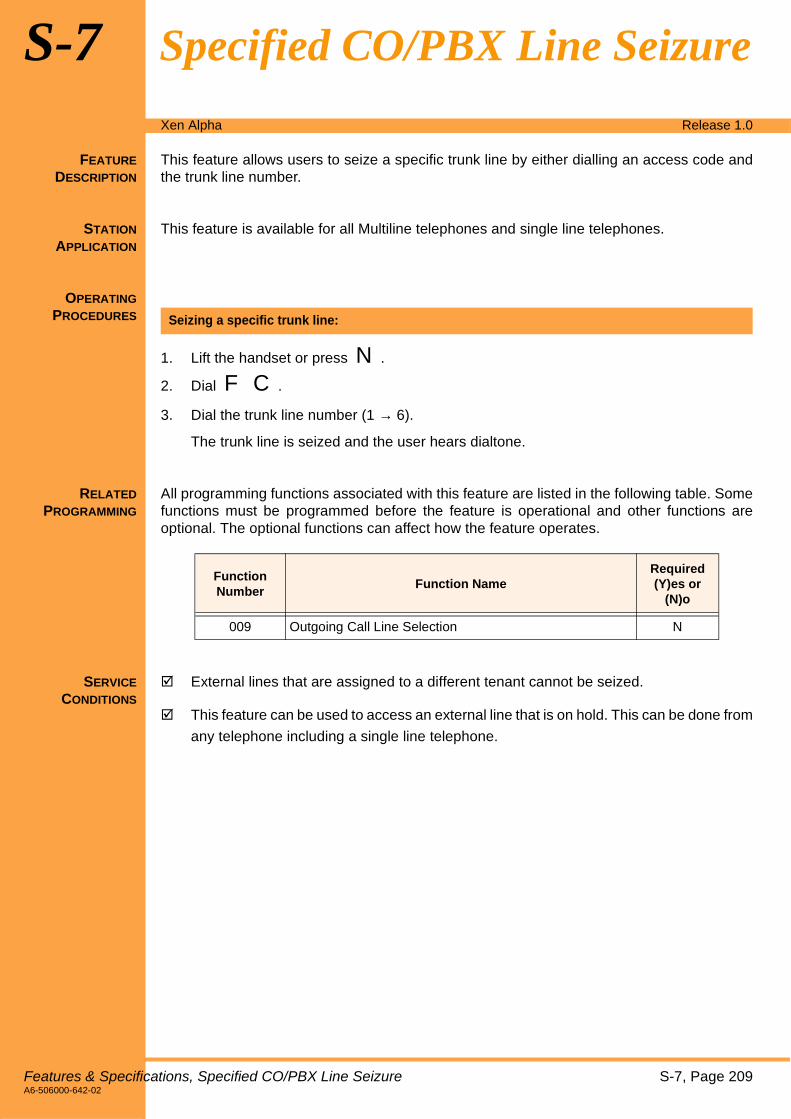
Xen Alpha Release 1.0
S-7 Specified CO/PBX Line Seizure
FEATURE
DESCRIPTION
This feature allows users to seize a specific trunk line by either dialling an access code andthe trunk line number.
STATION
APPLICATION
This feature is available for all Multiline telephones and single line telephones.
OPERATING
PROCEDURES
1. Lift the handset or press N.
2. Dial F C.
3. Dial the trunk line number (1 → 6).
The trunk line is seized and the user hears dialtone.
RELATED
PROGRAMMING
All programming functions associated with this feature are listed in the following table. Somefunctions must be programmed before the feature is operational and other functions areoptional. The optional functions can affect how the feature operates.
SERVICE
CONDITIONS
! External lines that are assigned to a different tenant cannot be seized.
! This feature can be used to access an external line that is on hold. This can be done from
any telephone including a single line telephone.
Seizing a specific trunk line:
Function Number
Function NameRequired(Y)es or
(N)o
009 Outgoing Call Line Selection N
Features & Specifications, Specified CO/PBX Line Seizure S-7, Page 209A6-506000-642-02

This page is intentionally blank.
Page 210, S-7 Features & SpecificationsA6-506000-642-02

Xen Alpha Release 1.0
S-8 Speed Dial – Station
FEATURE
DESCRIPTION
Each extension in the system can be allowed up to 20 personal speed dial numbers. Forpersonal speed dial numbers to be available, the system must be set to 80 mode in systemprogramming. Selecting 80 mode reserves 20 personal speed dial numbers for eachtelephone user.
STATION
APPLICATION
This feature is available for all Multiline and single line telephones. Single line telephonescan be used to set up and originate speed dialling but it cannot be used to confirm speeddial numbers.
OPERATING
PROCEDURES
1. Press O.
2. Press T (DTB-type telephones) or Q (DTU-type telephones).
3. Dial the speed dial memory location number (J J → A I).
4. Enter the desired telephone number (maximum of 24 digits).
If a pause is needed, press either T or Q. If a hookflash is needed, press either QorS. If nesting numbers, press R or Oto enter the brackets.
If entering an associated “name” (alphabetic characters), press U. (Refer toCharacter Registration, Page 65 for instructions about entering alphanumericcharacters.)
5. Press O.
1. Lift the handset.
2. Dial H E.
3. Dial the speed dial memory location number (J J → A I) where the telephonenumber is stored.
4. Enter the desired telephone number to be stored in the speed dial memory location.
5. Place the handset in the cradle.
Programming a speed dial number using a Multiline telephone:
Programming a speed dial number using a single line telephone:
Features & Specifications, Speed Dial – Station S-8, Page 211A6-506000-642-02

1. Press V (external line key).
2. Press T (DTB-type telephones) or Q (DTU-type telephones).
3. Dial the speed dial memory location number (J J → A I) where the telephonenumber is stored.
4. The number is automatically dialled.
1. Lift the handset.
2. Dial H C.
3. Dial the speed dial memory location number (J J → A I) where the telephonenumber is stored.
4. The number is automatically dialled.
1. Press O.
2. Press T (DTB-type telephones) or Q (DTU-type telephones).
3. Dial the speed dial memory location number (J J → A I) where the telephonenumber is stored.
If deleting the associated “name” (alphabetic characters), press U. If only deletingthe speed dial number, proceed to the next step.
4. Press O.
1. Lift the handset.
2. Dial H E.
3. Dial the speed dial memory location number (J J → A I) where the telephonenumber is stored.
4. Place the handset in the cradle.
1. Press P.
2. Press T (DTB-type telephones) or Q (DTU-type telephones).
3. Dial the speed dial memory location number (J J → A I) where the telephonenumber is stored.
4. The number is displayed in the telephone LCD.
Speed dialling using a Multiline telephone:
Speed dialling using a single line telephone:
Deleting a speed dial number using a Multiline telephone:
Deleting a speed dial number using a single line telephone:
Confirming a speed dial number using a Multiline telephone:
Page 212, S-8 Speed Dial – Station, Features & SpecificationsA6-506000-642-02

SERVICE
CONDITIONS
! Speed dial numbers are stored in redial memory. Speed dialling memory is stored in the
system’s backup battery.
! The maximum number of digits that can be stored in a speed dial memory location is 24.
If the user attempts to dial more than 24 digits, “ERROR” is displayed in the telephone
LCD for five seconds.
When a pause ( K) or hookflash ( L) is programmed as part of the speed dial number, it iscounted as a digit.
! If a user attempts to initiate speed dialling from a speed dial memory location that has
not been programmed, “XX: EMPTY or XXX: EMPTY is displayed in the telephone LCD.
(XX or XXX = Speed Dial Memory Location Number).
! If a call is originated for a speed dial memory location that has both the telephone
number and associated “name” programmed, the number and name are displayed in the
telephone LCD. Once the called party answers, the telephone LCD displays the clock.
! If a call is originated on a CO line using a stored speed dial number for which no PBX
access code is defined and the system supports both CO and PBX lines, the CO line is
released and an error tone is generated.
! Entering a pause, hookflash or nesting numbers is only available if programming speeddial numbers on Multiline telephones (i.e., these are not available when programmingspeed dial numbers on single line telephones).
! A maximum of five system and station ‘leave’ speed dial memory location numbers can
be programmed into one speed dial memory location.
! An external speed dial memory location number can be assigned to a one-touch/feature
access key.
! System speed dial numbers can be nested under station ‘leave’ speed dial memory
locations however, station speed dial numbers cannot be nested under system speed
dial memory locations.
! Contents of the speed dial memory location can be verified and cleared.
Features & Specifications, Speed Dial – Station S-8, Page 213A6-506000-642-02

This page is intentionally blank.
Page 214, S-8 Features & SpecificationsA6-506000-642-02

Xen Alpha Release 1.0
S-9 Speed Dial – System
FEATURE
DESCRIPTION
Speed dialling can be assigned on a system-wide basis. System speed dialling can be set to200 numbers or 80 numbers. If 200 is selected, individual users are not allowed to assignpersonal speed dialling numbers on their telephones. If 80 is selected, then each telephoneuser can set up to 20 personal speed dial numbers and 80 speed dial numbers are reservedfor system speed dialling.
STATION
APPLICATION
This feature is available for all Multiline and single line telephones. Single line telephonescan be used to set up and originate speed dialling but cannot be used to confirm speed dialnumbers. Programming, deleting and verifying speed dial numbers can only be performedusing an attendant telephone (ports 1 and 2).
OPERATING
PROCEDURES
1. Press O.
2. Press T (DTB-type telephones) or Q (DTU-type telephones).
3. Dial the speed dial buffer number where the number will be stored ( B J → I I or J J J → A I I).
4. Dial the telephone number (maximum 24 digits).
If a pause is needed, press either T or Q. If a hookflash is needed, press eitherQ orS. If nesting numbers, press R or O to enter the brackets.
5. If entering an associated ring pattern, press R key, then dial the pattern number 1to 4.
6. If entering an associated “name” (alphabetic characters), press U. (Refer toCharacter Registration, Page 65 for instructions about entering alphanumericcharacters.)
7. Press O.
1. Press V (outside line key).
2. Lift the handset.
3. When dialtone is heard, press T (DTB-type telephones) or Q (DTU-typetelephones).
4. Dial the appropriate speed dial buffer number( B J → I I or J J J → A I I).
Programming a speed dial number from an attendant telephone:
Placing a speed dial call in from a telephone in a key function (squared) system:
Features & Specifications, Speed Dial – System S-9, Page 215A6-506000-642-02

1. Press T (DTB-type telephones) or Q (DTU-type telephones).
2. When dialtone is heard, dial the appropriate speed dial buffer number( B J → I I or J J J → A I I).
1. Lift the handset.
2. When internal dialtone is heard, dial HC.
3. Dial the speed dial buffer number(B J → I I or J J J → A I I).
1. Press O.
2. Press T (DTB-type telephones) or Q (DTU-type telephones).
3. Dial the speed dial memory location number where the telephone number is stored(B J → I I or J J J → A I I).
If deleting the associated “name” (alphabetic characters), press U. If only deletingthe speed dial number, proceed to the next step.
4. Press O.
1. Press P.
2. Press T (DTB-type telephones) or Q (DTU-type telephones).
3. Dial the speed dial memory location number where the telephone number is stored(B J → I I or J J J → A I I).
4. The number is displayed in the telephone LCD.
Placing a speed dial call from a telephone in a multifunction (non-squared or hybrid) system:
Placing a speed dial call using a single line telephone:
Deleting a speed dial number using an attendant telephone:
Confirming a speed dial number using a Multiline telephone:
Page 216, S-9 Speed Dial – System, Features & SpecificationsA6-506000-642-02

SERVICE
CONDITIONS
! Speed dial numbers are stored in redial memory. Speed dialling memory is stored in the
system’s backup battery.
! The maximum number of digits that can be stored in a speed dial memory location is 24.
If the user attempts to dial more than 24 digits, “ERROR” is displayed in the telephone
LCD for five seconds.
When a pause (K) or hookflash (L) is programmed as part of the speed dial number, it iscounted as a digit.
! If a user attempts to initiate speed dialling from a speed dial memory location that has
not been programmed, “XX: EMPTY or XXX: EMPTY is displayed in the telephone LCD.
(XX or XXX = Speed Dial Memory Location Number).
! If a call is originated for a speed dial memory location that has both the telephone
number and associated “name” programmed, the number and name are displayed in the
telephone LCD. Once the called party answers, the telephone LCD displays the clock.
! If a call is originated on a CO line using a stored speed dial number for which no PBX
access code is defined and the system supports both CO and PBX lines, the CO line is
released and an error tone is generated.
! Entering a pause, hookflash or nesting numbers is only available if programming speed
dial numbers on Multiline telephones (i.e., these are not available when programming
speed dial numbers on single line telephones).
! A maximum of five system and station (personal) speed dial memory location numbers
can be programmed into one speed dial memory location.
! An external speed dial memory location number can be assigned to a one-touch/feature
access key.
! System speed dial numbers can be nested under station (personal) speed dial memory
locations however, station speed dial numbers cannot be nested under system speed
dial memory locations.
! Contents of the speed dial memory location can be verified and cleared.
! If a ring pattern (1 to 4) has been assigned to a system speed dial location, an incomingtrunk call whose CLI matches the stored number will ring according to that pattern. Thismay be different from the usual ringing pattern assigned to that phone and differentsystem speed dial locations can have different ring patterns assigned to them.
Features & Specifications, Speed Dial – System S-9, Page 217A6-506000-642-02

This page is intentionally blank.
Page 218, S-9 Features & SpecificationsA6-506000-642-02

Xen Alpha Release 1.0
S-10 Station Message Detail Recording (SMDR)
FEATURE
DESCRIPTION
Station Message Detail Recording provides detailed calls records of system telephoneusage. This feature is useful for controlling costs by identifying telephone users, trunkusages, and numbers dialled. SMDR supports the connection of call accounting equipmentthat audits local and long distance telephone bills.
An MIF-B13 ETU is required to support this feature.
STATION
APPLICATION
This feature is available for all Multiline telephones and single line telephones.
OPERATING
PROCEDURES
1. Press O.
2. Dial I F.
3. Press O.
RELATED
PROGRAMMING
All programming functions associated with this feature are listed in the following table. Somefunctions must be programmed before the feature is operational and other functions areoptional. The optional functions can affect how the feature operates.
To Switch Between PC Programming and SMDR Output Mode for MIF ETU:
Function Number
Function NameRequired(Y)es or
(N)o
002-9 Station Message Detail Recording N
024 Print Format N
025 Baud Rate to Printer N
026 Stop Bit for Printer N
Features & Specifications, Station Message Detail Recording (SMDR) S-10, Page 219A6-506000-642-02

SERVICE
CONDITIONS
! If a power failure occurs during a call, the call is terminated and the call record
information is lost.
! If the SMDR feature is disabled in system programming (Function “002-9 – Station
Message Detail Recording”), printout or data storage is not performed.
! SMDR only generates information for outgoing and transferred outgoing calls.
! If a printer is not connected to the system or if the printer is not operating, the MIF-B10ETU can store information for 200 calls. Once the memory is full, the oldest call recordis erased and the new record is stored.
! When the memory on the MIF-B13 ETU becomes 80% full, the system generates analert that is displayed on an attendant position telephone LCD. When the memory fallsbelow 80% the alert clears from the telephone LCD.
! Using O I F, the user manually switches between PC programming mode andSMDR mode. If PC programming mode is selected, SMDR data is stored in memory onthe MIF-B13 ETU. If SMDR mode is selected, SMDR data is sent to the printerconnected to the MIF-B13 ETU.
If a PC is connected to the system instead of a printer and SMDR mode has beenselected, SMDR data is output to the PC (i.e., no data is stored in memory on the MIF-B13 ETU).
! When the printer is connected, data stored in memory on the MIF-B13 ETU is printed
out. New call records are printed as they are received.
! No record is generated if the caller hangs up before the elapsed call timer starts.
! The print format is:
! The EIA RS-232C port, used to interface with the external device, must conform to the
following specifications:
Synchronization: Start/Stop
Data Length: 8 bits
Parity Bits: None
Stop Bits: 1
Start Bits: 1
Baud Rate: 1200, 2400, 4800 or 9600 bps
Cable: RS-232C (D-sub, 9-pin) straight
10 1 OUT 01-25 09:15:25 09:17:30 9727517626
External LineNumber
Type ofCall
Call StopTime
Dialled TelephoneNumber
Month Day
ExtensionNumber
Call StartTime
OUT = Outgoing Call TRF = Transferred Call
Page 220, S-10 Station Message Detail Recording (SMDR), Features & SpecificationsA6-506000-642-02

Xen Alpha Release 1.0
S-11 Step Call
FEATURE
DESCRIPTION
This feature allows a user, who calls a busy extension, to call the next extension number inthe system by simply dialling a preassigned digit. This can be done without having to hangup between call attempts.
STATION
APPLICATION
This feature is available for all Multiline telephones and single line telephones.
OPERATING
PROCEDURES
1. Dial another extension number.
2. If that extension is also busy, continue this process until you reach an idle extensionnumber.
RELATED
PROGRAMMING
All programming functions associated with this feature are listed in the following table. Somefunctions must be programmed before the feature is operational and other functions areoptional. The optional functions can affect how the feature operates.
Using the Step Call feature when calling a busy extension:
Function Number
Function NameRequired(Y)es or
(N)o
206 Extension Number Assignment N
Features & Specifications, Step Call S-11, Page 221A6-506000-642-02

This page is intentionally blank.
Page 222, S-11 Features & SpecificationsA6-506000-642-02

Xen Alpha Release 1.0
S-12 Stored Hookflash
FEATURE
DESCRIPTION
This feature allows a hookflash to be stored in a speed dial memory location. This allowsMultiline telephone users to store the hookflash which is used to allow access to featuressuch as transferring calls, conferencing, in a speed dial buffer, etc.
STATION
APPLICATION
This feature is available for all Multiline telephones.
OPERATING
PROCEDURES
1. Press O.
2. Press T (DTB-type telephones) or Q (DTU-type telephones).
3. Enter the speed dial memory location number.
4. Press Q (DTB-type telephones) or S (DTU-type telephones). This entersa hookflash.
5. Enter the telephone number to be stored in the speed dial memory location.
6. Press O.
1. Press O.
2. Press T (DTB-type telephones) or Q (DTU-type telephones).
3. Press the one-touch/feature access key where the number will be stored.
4. Press K.
5. Press Q (DTB-type telephones) orS(DTU-type telephones).
6. Enter the telephone number to be stored in the speed dial memory location.
7. Press O.
Note: The external line must be assigned as a PBX line using Function “107 –TrunkLine Type”.
Programming a hookflash on a one-touch/feature access key for speed dialling:
Programming a hookflash on a one-touch/feature access key for speed dialling when the external line is a PBX line:
Features & Specifications, Stored Hookflash S-12, Page 223A6-506000-642-02

RELATED
PROGRAMMING
All programming functions associated with this feature are listed in the following table. Somefunctions must be programmed before the feature is operational and other functions areoptional. The optional functions can affect how the feature operates.
SERVICE
CONDITIONS
! This feature is only available for Multiline telephones.
! A hookflash can be entered for system and station speed dial numbers.
Function Number
Function NameRequired(Y)es or
(N)o
107 Trunk Line Type N
Page 224, S-12 Stored Hookflash, Features & SpecificationsA6-506000-642-02

Xen Alpha Release 1.0
T-1 Telephone Volume Control
FEATURE
DESCRIPTION
This feature allows Multiline Telephone users to control the handset and the speaker/ringingvolume by pressing the up and down volume buttons on the telephone. It also allows theuser to change the contrast on the LCD of the DTU-type Multiline telephones.
STATION
APPLICATION
This feature is available for all Multiline telephones.
OPERATING
PROCEDURE
1. Press N or lift the handset.
2. Dial H G.
3. Dial A.
4. Press W (▲= louder or ▼= softer) to increase or decrease the volume (Mfor DTU-
type telephones, ∧ = louder or ∨ = softer).
1. Press P .
2. Dial HG.
3. Dial B.
4. PressM(▲ = darker ▼ = lighter) to increase or decrease the LCD contrast.
5. Go on-hook.
- OR -
While the telephone is idle, pressM(∧ = darker ∨ = lighter) to increase or decrease theLCD contrast.
1. Press N.
2. Dial H G.
3. Dial A.
4. Lift the handset.
5. Press W (▲= louder or ▼= softer) to increase or decrease the volume (Mfor DTU-
type telephones, ∧ = louder or ∨ = softer).
Changing the on-hook ringing volume:
Changing the LCD contrast (DTU-type telephones only):
Changing the off-hook ringing volume:
Features & Specifications, Telephone Volume Control T-1, Page 225A6-506000-642-02

1. Press N or lift the handset.
2. Press W (▲= louder or ▼= softer) to increase or decrease the volume (Mfor DTU-
type telephones, ∧ = louder or ∨ = softer).
1. Press N.
2. Press W (▲= louder or ▼= softer) to increase or decrease the volume (Mfor DTU-type telephones, ∧ = louder or ∨ = softer).
3. Go on-hook.
- OR -
While using the speakerphone, press W (+= louder or ,= softer) to increase or
decrease the volume (Mfor DTU-type telephones, ∧ = louder or ∨ = softer).
SERVICE
CONDITIONS
! LCD contrast can be adjusted usingM(DTU-type Multiline telephones only).
! The manual volume and contrast settings are preserved regardless of the original setting
in system programming.
! When the user presses the volume key W (▲= louder or ▼= softer) on a DTB-type
telephone while the telephone is in the idle condition, the volume of incoming calls is
adjusted. When the user presses the volume keyM(∧ = darker or ∨ = lighter) on a DTU-type
telephone while the telephone is in the idle condition, the LCD contrast is adjusted.
Changing the handset receiver volume:
Setting speaker volume:
Page 226, T-1 Telephone Volume Control, Features & SpecificationsA6-506000-642-02
Xen Alpha Release 1.0
T-2 Tenant Service
FEATURE
DESCRIPTION
This feature allows the outside lines to be subdivided in into two tenant groups or call pickupgroups. This allows each tenant to have access to their own assigned outside line. Userscannot pick up calls coming into another tenant group.
OPERATING
PROCEDURES
RELATED
PROGRAMMING
All programming functions associated with this feature are listed in the following table. Somefunctions must be programmed before the feature is operational and other functions areoptional. The optional functions can affect how the feature operates.
SERVICE
CONDITIONS
! Each external line and telephone is assigned to tenants 1 or 2 using systemprogramming. At default, all external lines and telephones are assigned to tenant 1.
! Each external line can be assigned to more than one tenant (i.e., duplicate tenantallowed). However, telephones can only be a member of one tenant group (i.e., duplicatetenants are not allowed).
! CO/PBX LEDs associated with other tenants will not light when in use.
! The following features are available when users are members of different tenant groups:
• All Call Page, Page 3
• Automatic Callback, Page 13
• Call Pickup Group, Page 55
• Call Transfer, Page 61
• Conference Add-On, Page 73
• Internal Voice/Tone Signaling, Page 141
• Step Call, Page 221
• Tone Override, Page 231
! The following features are not available when users are members of differenttenant groups:
• Barge-In (Interrupting an External Call), Page 29
• Holdfree Transfer, Page 127
• Manual Line Seizure, Page 153
• Privacy On All Calls, Page 183
• Specified CO/PBX Line Seizure, Page 209
• Trunk Queuing, Page 235
Not applicable.
Function Number
Function NameRequired(Y)es or
(N)o
401 Trunk Line Assignment for Tenant 1 Y
402 Trunk Line Assignment for Tenant 2 Y
403 Tenant-to-Telephone Assignment Y
Features & Specifications, Tenant Service T-2, Page 227A6-506000-642-02

This page is intentionally blank.
Page 228, T-2 Features & SpecificationsA6-506000-642-02

Xen Alpha Release 1.0
T-3 Timed Alarm
FEATURE
DESCRIPTION
A timed alarm can be set to any Multiline telephone as a reminder of a scheduled time. Theuser can program the system to automatically send a reminder alarm to their telephone. Twotimed alarms are available system-wide.
STATION
APPLICATION
This feature is available for all Multiline telephones.
OPERATING
PROCEDURES
1. Press O.
2. Dial E B (Alarm 1) or E E (Alarm 2).
3. Enter the time (hours and minutes) when you want the alarm to sound.
4. Press O.
1. Press O.
2. Dial E A (Alarm 1) or E D (Alarm 2).
3. Press O.
1. Press O.
2. Dial E J (Alarm 1) or E C (Alarm 2).
3. Press O.
1. Press O.
2. Dial E H.
3. Press O.
Setting a timed alarm:
Cancelling a timed alarm:
Confirming a timed alarm :
Cancelling a timed alarm: (attendant position only):
Features & Specifications, Timed Alarm T-3, Page 229A6-506000-642-02

SERVICE
CONDITIONS
! In the following cases, no alarm is sounded:
• A handsfree call is in progress or room monitoring is in progress.
• An internal voice announced call or tone signal call is being received.
• An incoming doorphone ringing call.
! Alarm 1 automatically resets (releases) when it sounds.
! Alarm 2 does not reset, it sounds each day at an preassigned time.
! If both alarms are set to the same time, only alarm 1 sounds. Alarm 2 will sound at thenext preassigned time.
! A user can cancel an alarm that sounds at their telephone by pressing any of the keyson the telephone (except the volume key).
! Feature access codes and preset times can be assigned to a one-touch/feature accesskey. When a timed alarm sounds, the LED on the one-touch/feature access key (wherethe access code or time is assigned) lights red while the alarm sounds.
! When an alarm sounds, “ALARM: X” is shown in the telephone display for 10 seconds.(X = 1 or 2)
! An alarm can sound when the user has a call in progress.
! Preset times must be specified in military time (24 hour clock = 00:00 → 23:59).
! Only attendant positions can be used to reset alarms system-wide.
! Both alarms can be reset system-wide.
! When a timed alarm is set on a DTB-type Multiline telephone, a clock icon is also shownin the telephone display. The icon disappears when Alarm 1 ends, however if Alarm 2 isset, the clock is continually displayed.
Page 230, T-3 Timed Alarm, Features & SpecificationsA6-506000-642-02

Xen Alpha Release 1.0
T-4 Tone Override
FEATURE
DESCRIPTION
Tone Override is used by one user to signal another user, who is engaged on a call, that theyhave an incoming call. The called party can answer the incoming call by putting the existingcall on hold.
This feature also allows the user to switch between a tone override call and an existing call.When the user answers the tone override call, the existing call is put on hold. By pressingR , the user can switch between the two calls.
STATION
APPLICATION
This feature is available for all Multiline and Single Line telephones.
OPERATING
PROCEDURES
1. After hearing a tone, dial K (set as default) to send the override tone.
2. After hearing a confirmation tone, wait for the called party to answer call
After hearing the override tone, press M and talk with the calling party.
1. After hearing the override tone, press M to put the existing call on hold and to answeroverride call.
2. Talk with the override caller.
3. To switch between the two callers, press R.
SERVICE
CONDITIONS
! This feature is not available if the telephone is in one of the following conditions:
• The telephone is being used to assign one-touch/feature access keys, speed dial numbers,scrolling, etc.
• The telephone is being used to program the system.
• A Single Line telephone is called.
• The called telephone is set to do not disturb.
Originating a Tone Override:
Answering a Tone Override:
Answering the override call and switching between callers:
Features & Specifications, Tone Override T-4, Page 231A6-506000-642-02

! Tone override is only enabled when the called telephone is busy.
! The user can answer the tone override by pressing M (during an internal/external callor while engaged in an add-on conference).
! A Single Line telephone has 30 seconds to send a tone override before it is disabled.
! If the user is speaking on the speakerphone and a tone override is received, the speechpath is temporarily disrupted and the party sending the tone override hears a callwaiting tone.
! When tone override is released, the telephone display returns to the previous condition.
! A telephone cannot receive multiple tone overrides.
! If a user is engaged on an external call and hangs up while a tone override is beingreceived, the call becomes an internal call.
! A tone override call can be made to users who are members of another tenant group.
! The tone override tone is generated each time the tone override operation is performed.
Page 232, T-4 Tone Override, Features & SpecificationsA6-506000-642-02

Xen Alpha Release 1.0
T-5 Trunk Outgoing Restriction
FEATURE
DESCRIPTION
When telephones are assigned this feature, users are restricted from making some (or all)external calls (such as long distance calls). Users can continue to answer calls however ormay be able to make internal calls only. What is restricted is determined by individual needsand is programmed in system programming.
STATION
APPLICATION
This feature is available for all Multiline telephones and Single Line telephones.
OPERATING
PROCEDURES
RELATED
PROGRAMMING
All programming functions associated with this feature are listed in the following table. Somefunctions must be programmed before the feature is operational and other functions areoptional. The optional functions can affect how the feature operates.
SERVICE
CONDITIONS
! A telephone that has outgoing restriction enabled cannot bypass the restriction bypressing Q (DTB-type Multiline telephones) orS (DTU-type Multiline telephones)when a call is received. If the user attempts to make a call, the call is disconnected and“ERROR” is displayed in the telephone LCD.
! At system default, all external lines and all telephones are enabled for both incoming andoutgoing calls.
! Outgoing restriction can be programmed for each external line and telephone usingsystem programming.
Depends on how this feature is programmed.
Function Number
Function NameRequired(Y)es or
(N)o
351 → 356 Restricting Outgoing Calls for Trunk Lines 1 → 6 Y
Features & Specifications, Trunk Outgoing Restriction T-5, Page 233A6-506000-642-02

This page is intentionally blank.
Page 234, T-5 Features & SpecificationsA6-506000-642-02
Xen Alpha Release 1.0
T-6 Trunk Queuing
FEATURE
DESCRIPTION
When all outside lines are busy, telephone users can queue onto the busy line. When theline becomes available the system rings the telephone user to notify them that the a line isavailable. The user can cancel the queue at any time.
STATION
APPLICATION
This feature is available for all Multiline telephones and Single Line telephones.
OPERATING
PROCEDURES
1. Press the appropriate line key
- OR -.
Lift the handset or press N.
2. Dial I.
3. When you hear the busy tone, dial F H. The telephone display indicates the queueis set.
4. When you hear the recall, lift the handset or press N.
5. Dial the desired telephone number.
1. Lift the handset or press N.
2. Dial F I. The telephone display indicates the queue is canceled.
RELATED
PROGRAMMING
All programming functions associated with this feature are listed in the following table. Somefunctions must be programmed before the feature is operational and other functions areoptional. The optional functions can affect how the feature operates.
Setting trunk queuing when all external lines are busy:
Cancelling trunk queuing:
Function Number
Function NameRequired(Y)es or
(N)o
001-6 Trunk Line Direct Access N
002-8 Private Call N
209 Outgoing Call Priority Mode N
Features & Specifications, Trunk Queuing T-6, Page 235A6-506000-642-02

SERVICE
CONDITIONS
! Trunk queuing is not allowed if the telephone is a member of a different tenant group.
! Trunk queuing is enabled for the following conditions:
• When F C and the trunk number are dialed to seize a specific external line.
• When dial access code J is dialed.
• When the telephone is set for external line preference.
! If the telephone is not set to seize an external line, trunk queuing is disabled for thattelephone and an error tone is heard when trunk queuing is attempted.
! The following messages are displayed when trunk queuing is enabled/disabled:
• Enabled = TRUNK QUE SET
• Disabled = TRUNK QUE CNCL
! If the telephone is equipped with an LCD, “LINE IDLE” is displayed to notify the user theline is now available.
! The system provides ring notification to the telephone that set trunk queuing for 10seconds. After 10 seconds, ringing stops and trunk queuing is released.
! If trunk queuing is set to an external line and an incoming call is received on that line,trunk queuing notification is delayed until after that telephone is idle.
! If there is more than one telephone queued to the same external line, the recall isgenerated in the order in which the telephones set trunk queuing. If one of the queuedtelephones is busy when recall is attempted, the recall is directed to the next idletelephone. The busy telephone remains in the queue and will be recalled when thetelephone becomes idle.
Page 236, T-6 Trunk Queuing, Features & SpecificationsA6-506000-642-02

Xen Alpha Release 1.0
T-7 Two-Color LEDs (Lamp)
FEATURE
DESCRIPTION
The system provides two-color (red and green) LEDs to provide various status indications ofthe telephone. Hold and call waiting are a couple of example of status indications.
STATION
APPLICATION
This feature is available for all Multiline telephones.
OPERATING
PROCEDURES
SERVICE
CONDITIONS
! The line keys on all Multiline telephones can light both red and green.
! The LED lights green for the following feature and red for all other features:
• Call Transfer, Page 61
• Hold with Recall (Exclusive and Non-Exclusive), Page 129
• I-Hold Indication, Page 135
• I-Use Indication, Page 149
! The large LED on the DTU-type Multiline telephone flashes Green for incoming trunkcalls and Red for incoming ICM, DID, DIT and CO Ring Transferred calls. The large LEDon the DTB-type Multiline telephone flashes Red for all incoming calls.
Not applicable.
Features & Specifications, Two-Color LEDs (Lamp) T-7, Page 237A6-506000-642-02

This page is intentionally blank.
Page 238, T-7 Features & SpecificationsA6-506000-642-02

Xen Alpha Release 1.0
U-1 User Programming
FEATURE
DESCRIPTION
Users are allowed to program the following features using their Multiline telephones andSingle Line telephones.
" Ancillary Device Connection, Page 5
" Attendant Positions, Page 11
" Call Forward – All Calls, Page 41
" Call Forward – Busy/No Answer, Page 43
" Clock/Calendar Display, Page 69
" Character Registration, Page 65
" Distinctive Ringing, Page 87
" Extension Name Assignment, Page 99
" Incoming Call Identification, Page 137
" Nesting Dial, Page 161
" Off-Hook Ringing, Page 169
" One-Touch/Feature Access Keys – User Programmable, Page 171
" Programmable Pause for Speed Dial, Page 185
" Speed Dial – System, Page 215
" Stored Hookflash, Page 223
" Timed Alarm, Page 229
SERVICE
CONDITIONS
! Feature programming must be done while the system is idle.
Features & Specifications, User Programming U-1, Page 239A6-506000-642-02

This page is intentionally blank.
Page 240, U-1 Features & SpecificationsA6-506000-642-02

Xen Alpha Release 1.0
Appendix - A
FEATURE ACCESS
CODES &SPECIAL
NUMBERS LIST
This section provides a list of the feature access code and the special numbers that are usedwhen programming and operating the system. Feature Access Codes are codes that are enteredto access certain features of the system. Before using feature access codes, the user mustpress O before and after entering the code. Special Internal Dials Numbers are numbers orcodes that are entered to access certain functions of the system. Before entering these specialnumbers, the user must first press an external line and get internal dialtone. All of these codesare fixed in the system. This means that these codes cannot be changed by the user.
Table A-1: Feature Access Codes List
Access Code
Description
1 Handsfree Answer Set/Cancel
2 Handset Mute Set/Cancel
3 Seized Trunk Number DisplayInternal System Hold
4 Station Number VerifyManual Pause
6 Door Lock Release
6* Internal Hunt
65 Internal Do Not Disturb Set/Cancel
66** Call Forward – All Calls Cancel - SLT
66 Call Forward – All Calls Cancel – MLT
66XX Call Forward – All Calls Set! XX = Extension Numbers 10$59 or Trunk Access Code.
67 Call Forward – Busy/No Answer Cancel
67** Call Forward – Busy/No Answer Cancel – SLT
67XX Call Forward – Busy/No Answer Set! XX = Extension Numbers 10$59 or Trunk Access Code.
68 Call Forward – All Calls CancelCall Forward – Busy CancelCall Forward – No Answer (All Telephones) CancelDo Not Disturb Cancel! This feature is only available for telephones assigned to ports 1 and 2.
690 Incoming Ring Mode (All Modes for Incoming Calls)
691 Incoming Ring Mode (Telephone Mode)
Features & Specifications Manual – Appendix A Page - 241A6-506000-642-02

692 Incoming Ring Mode (Common Mode)
7 Privacy Release (Outside Line Calls)
75 Low Battery LCD Indication Reset! This feature is only available for telephones assigned to ports 1 and 2.
10 Headset Off-Hook/On-Hook Button
50 Timed Alarm Verify (Alarm 1)
51 Timed Alarm Cancel (Alarm 1)
52 Timed Alarm Set/Cancel (Alarm 1)
53 Timed Alarm Verify (Alarm 2)
54 Timed Alarm Cancel (Alarm 2)
55 Timed Alarm Set/Cancel (Alarm 2)
56 Room Monitored Telephone Set/Cancel
57 Room Monitoring Telephone Set/Cancel
58 All Telephone Alarm Clear! This feature is only available for telephones assigned to ports 1 and 2.
80 Night Mode Set/Cancel
84XX Extension Name Entry (Internal Calls)! XX = Extension Numbers 10$59
85X Trunk Name Entry (External Call)! X = Outside Line (1$6)
88 Callback Indication Reset
9 # Date/Time Set
9 * Test Printing (SMDR)! This feature is only available for telephones assigned to ports 1 and 2.
91 Malicious Call Trace! Available during an incoming ISDN call only.
93 Background Music Telephone Set/Cancel
96 SMDR Printout Start/Stop Toggle (Stop = PC Programming Mode)! This feature is only available for telephones assigned to ports 1 and 2.
99 Feature LED (Lamp) Reset
Table A-1: Feature Access Codes List
Access Code
Description
Page - 242 Features & Specifications Manual – Appendix AA6-506000-642-02

Table A-2: Special Internal Dial Numbers List
Access Code
Description
0 Auto Answer Assignment (Trunk Pickup)
10 → → → → 59 Internal Extension Number Range
60 Call Pickup from a different Tenant Group
61 Call Pickup Internal/External from the same Tenant Group
63X Specified CO/PBX Line Seizure! X = Outside Lines 1$6
65 Do Not Disturb Set/Cancel
66 Call Forward – All Calls Cancel
66XX Call Forward – All Calls Set/Cancel! XX = Extension Numbers 10$59 or Trunk Access Code.
6700 Call Forward – Busy/No Answer
67XX Call Forward – Busy/No Answer Set/Cancel! XX = Extension Numbers 10$59 or Trunk Access Code.
68 Trunk Queuing
69 Trunk Queuing Cancel
70 Internal All Call Page
74 Page Answer
75 External Paging
77 Internal/External All Call Page
79 Call Pickup (ISDN lines)
81 Doorphone 1 Monitor
82 Doorphone 2 Monitor
871 Ringer/Volume Adjustment
872 Contrast Adjustment! This applies to DTU-Type telephones only.
Features & Specifications Manual – Appendix A Page - 243A6-506000-642-02

This page is intentionally blank.
Page - 244 Features & Specifications Manual – Appendix AA6-506000-642-02

Xen Alpha Release 1.0
Appendix - B
TONE PATTERNS This chart provides the frequency and tone cycle patterns for the tones. Tones are used by thesystem to inform users of system functions such as dial tone, busy tone and ringback tone. Notethat the tones and frequencies are listed for each type of telephone the Xen Alpha systemsupports. In the chart (I) beside the frequency indicates the Xen Alpha telephone and (E)indicates the DTU-Type telephones.
Table B-1: Tone Patterns
System Tone(Fixed)
Frequency (Hz)(Fixed)
Modulation Cycle
Automatic Callback 500 Hz (I)540 Hz (D)
N/A
Barge-In Tone 440 Hz N/A
Busy Tone 480 Hz620 Hz
N/A
Call Waiting Tone 440 Hz N/A
CO/PBX RingTone A
High:1024 Hz/1285 Hz (I)1100 Hz/1400 Hz (E)
Low:480 Hz/606 Hz (I)520 Hz/660 Hz (E)
16
CO/PBX RingTone B
High:1024 Hz/1285 Hz (I)1100 Hz/1400 Hz (E)
Low:480 Hz/606 Hz (I)520 Hz/660 Hz (E)
16
CO/PBX RingTone C
High:1024 Hz/1285 Hz (I)1100 Hz/1400 Hz (E)
Low:480 Hz/606 Hz (I)520 Hz/660 Hz (E)
16
CO/PBX RingTone D
High:1024 Hz/1285 Hz (I)1100 Hz/1400 Hz (E)
Low:480 Hz/606 Hz (I)520 Hz/660 Hz (E)
16
ON
OFF
0.5 sec.
0.5 sec.
ON
OFF
1 sec.
ON
OFF
0.5 sec.
0.5 sec.
ON
OFF
0.5 sec.
0.5 sec.
ON
OFF
2 sec.
4 sec.
.375 sec.
ON
OFF .250 sec.
ON
OFF
.250 sec.
.125 sec.
ON
OFF
0.5 sec.
0.5 sec.
Features & Specifications Manual – Appendix B Page - 245A6-506000-642-02

Doorphone1
Chime Tone
N/A N/A
Busy Chime Tone
1400 Hz/1100 Hz (I & E)
N/A
Doorphone2
Chime Tone
N/A N/A
Busy Chime Tone
1024 Hz (I)1100 Hz (E)
N/A
Hold Alarm 1024 Hz (I)1100 Hz (E)
N/A
Howler Tone 2400 Hz (I & E)
16 100% AM
Incoming Dial Tone 360 Hz/440 Hz (I & E)
N/A
Incoming Ring Transfer 480 Hz/606 Hz (I)520 Hz/660 Hz (E)
16
Internal Ring Tone 500 Hz (I)540 Hz (E)
N/A
Key Tone 1100 Hz (I & E) N/A
Recall Tone 1024 Hz (I & E) N/A
Reorder Tone 480/620 Hz N/A
System Tone(Fixed)
Frequency (Hz)(Fixed)
Modulation Cycle
ON
OFF
1400 Hz
ON
OFF 1100 Hz
ON
OFF
ON
OFF
.250 sec.
.250 sec.
ON
OFF
0.5 sec.
0.5 sec.
.032 sec.ON
OFF .032 sec.
Continuous
ON
OFF
ON
OFF
0.5 sec.
0.5 sec.
ON
OFF
0.5 sec.
0.5 sec.
ON
OFF
.070 sec.
ON
OFF
0.5 sec.
0.5 sec.
ON
OFF
.250 sec.
.250 sec.
Page - 246 Features & Specifications Manual – Appendix BA6-506000-642-02

Ringback Tone for External Speaker CO/
PBX Ring Tone
440 Hz/480 Hz(I & E)
N/A
Ringing Transfer Alarm 1024 Hz (I)1100 Hz (E)
N/A
Set Tone 1 800 Hz(I & E)
N/A
Set Tone 2 500 Hz (I)540 (E)
N/A
Timed Alarm 1024 Hz (I)1100 Hz (E)
N/A
Tone Override 500 Hz (I)540 HZ (E)
N/A
Trunk Queuing 500 Hz (I)540 HZ (E)
N/A
System Tone(Fixed)
Frequency (Hz)(Fixed)
Modulation Cycle
ON
OFF
1 sec.
2 sec.
ON
OFF
0.5 sec.
0.5 sec.
ON
OFF
.700 sec.
ON
OFF
0.5 sec.
ON
OFF
.250 sec.
.125 sec.
ON
OFF
2 sec.
ON
OFF
0.5 sec.
0.5 sec.
Features & Specifications Manual – Appendix B Page - 247A6-506000-642-02

This page is intentionally blank.
Page - 248 Features & Specifications Manual – Appendix BA6-506000-642-02

Xen Alpha Release 1.0
Appendix - C
GLOSSARY OF
TERMS
This glossary is provided to help you understand terms and abbreviations used throughoutthis document.
Table C-1: Glossary of Terms
Term Definition
Central Office (CO) Telephone company facility where subscribers' lines are joined to switching equipment for connecting other subscribers to each other, locally and long distance. Also called CO, as in See-Oh. Sometimes the term central office is the same as the overseas term "public exchange." Sometimes, it means a wire center in which there might be several switching exchanges.
CO Refer to Central Office
Dial Pulse (DP) A means of signaling consisting of regular momentary interruptions of a direct or alternating current at the sending end in which the number of interruptions corresponds to the value of the digit or character. In short, the old style of rotary dialing. Dial the number "five" and you will hear five "clicks." See also DTMF.
Dual Tone Multifrequency (DTMF)
Dual Tone Multi-Frequency. A fancy term describing push button or Touchtone dialing. (Touchtone is a not registered trademark of AT&T, though until 1984 it was.) In DTMF, when you touch a button on a push button pad, it makes a tone, actually a combination of two tones, one high frequency and one low frequency. Thus the name Dual Tone Multi Frequency. In U.S. telephony, there are actually two types of "tone" signaling, one used on normal business or home push button/touchtone phones, and one used for signaling within the telephone network itself. See also Dial Pulse.
DP Refer to Dial Pulse.
DTMF Refer to Dual Tone Multifrequency.
Hybrid System This term is used to describe a system which has attributes of both Key Telephone Systems and PBXs. The distinguishing feature is that a hybrid key system can use normal single line phones in addition to the normal electronic key phones. A single line phone behind a hybrid works very much like a single line phone behind a PBX. The second distinguishing feature of a hybrid is that it is "non-squared." This means that not every trunk appears as a button on every phone in the system. In a non-squared system, you can have more trunks than you have buttons on each telephone. Some telephones will have trunks that others do not have and vice versa. This allow you to have more trunks on your telephone system than you have buttons on your telephones. This means, for example, that four executives can each have private lines and access to four trunks on a six-button telephone.
Features & Specifications Manual – Appendix C Page - 249A6-506000-642-02

ISDN Integrated Services Digital Network. ISDN comes today in two basic flavors -- BRI, which is 144,000 bits per second and designed for the desktop, and PRI which is 1,544,000 bits per second and designed for telephone switches, computer telephony and voice processing systems. Neither ISDN BRI or ISDN PRI is a standard service, though there are several "standard" configurations. ISDN BRI is a wonderful service in your home or office because it can give you video conferencing, and ultrafaster data communications.
Key Function (KF) Refer to Squared System
Key Service Unit (KSU)
The Key Service Unit is the main cabinet containing all the equipment, switching and electronics necessary to run a key telephone system.
KF Refer to Squared System
KSU Refer to Key Service Unit.
LCD Refer to Liquid Crystal Display
Liquid Crystal Display (LCD)
Liquid Crystal Display. An alphanumeric display using liquid crystal sealed between two pieces of glass. The display is divided into hundreds or thousands of individual dots, which are charged or not charged, reflecting or not reflecting external light to form characters, letters and numbers. LCD displays have certain advantages. They use little electricity and react reasonably quickly.
MF Refer to Hybrid System.
Multifunction System (MF)
Refer to Hybrid System.
PBR Push Button Receiver. Instead of rotary dialing, buttons are pushed to generate the tones needed to place a phone call. Also called Touchtone or DTMF.
Rotary Dialing Refer to Dial Pulse
PBX Private Branch eXchange. A private (i.e. you, as against the phone company owns it), branch (meaning it is a small phone company central office), exchange (a central office was originally called a public exchange, or simply an exchange). In other words, a PBX is a small version of the phone company's larger central switching office. A PBX is also called a Private Automatic Branch Exchange, though that has now become an obsolete term. In the very old days, you called the operator to make an external call, except in Europe. Then later someone made a phone system that you simply dialed nine (or another digit -- in Europe it's often zero), got a second dial tone and dialed some more digits to dial out, locally or long distance. So, the early name of Private Branch Exchange (which needed an operator) became Private AUTOMATIC Branch Exchange (which didn't need an operator). Now, all PBXs are automatic. And now they're all called PBXs, except overseas where they still have PBXs that are not automatic
Squared System A squared system is a system where each trunk line "appears" as the same button on each phone. The major advanced of the squared system is that you can go to any telephone anywhere in the system and punch any button for any trunk line and know it to be the same button for the same trunk line. This makes telephone operation less confusing. However, there is a limitation to this configuration, you can only have as many trunks on your key system as you have trunk buttons on your key telephones. (See also, Hybrid System.)
Table C-1: Glossary of Terms
Term Definition
Page - 250 Features & Specifications Manual – Appendix CA6-506000-642-02

Switch A mechanical, electrical or electronic device which opens or closes circuits, completes or breaks an electrical path, or selects paths or circuits.
Tenant Service Some businesses acquire a telephone system too large for their needs so they sell parts of the service to smaller offices in their own building or in the surrounding community. There are two ways to make money on tenant service -- renting telephone equipment or reselling long distance lines. There's more money on re-selling long distance lines.
Touchtone Dialing Refer to Dual Tone Multifrequency.
Trunk Line A communication line between two switching systems. The term switching systems typically includes equipment in a central office (the telephone company) and PBXs. A tie trunk connects PBXs. Central office trunks connect a PBX to the switching system at the central office.
Table C-1: Glossary of Terms
Term Definition
Features & Specifications Manual – Appendix C Page - 251A6-506000-642-02

This page is intentionally blank.
Page - 252 Features & Specifications Manual – Appendix CA6-506000-642-02