failure mode and criticality analysis of transmission system · been developing to quantify the...
TRANSCRIPT

International Research Journal of Engineering and Technology (IRJET) e-ISSN: 2395 -0056
Volume: 03 Issue: 04 | Apr-2016 www.irjet.net p-ISSN: 2395-0072
© 2016, IRJET | Impact Factor value: 4.45 | ISO 9001:2008 Certified Journal | Page 2719
Failure Mode and Criticality Analysis of Transmission System
Prashant Jagtap1, Pravin Nadkarni2, Vijay Patil3
1Student,AISSMS COE, Pune, Maharashtra, India 2 Manufacturing Quality Head, PIAGGIO Vehicles Pvt Ltd, Baramati, Maharashtra, India
3Professor, Dept. of Mechanical Engineering, AISSMSCOE, Pune, Maharashtra, India
---------------------------------------------------------------------***---------------------------------------------------------------------Abstract -Transmission system problems is a complicated
which automobile manufacturers have confronted for
decades. Customer complaints result in significant yearly
warranty costs. More importantly, customer dissatisfaction
may result in rejection. In order to produce quality
automobiles that can compete in today’s marketplace, the
occurrence of transmission system problem must be
reduced. The purpose of this report is to discuss
transmission system problem and solution for the problems
occur. The different tools are used to solving the problems of
transmission system. Failure modes of system are different
like braking, noise, jerking, wear & leakage all these reasons
of failure. The criticality is depending on the how the
problem is affect to system. Also there are many methods to
find the criticality of problem in whole system by the
severity, occurrence and detection as used in a FMEA.When
the failure modes have been ranked, corrective action
should first be directed at the highest ranked concerns and
critical items. If the causes are not fully understood, a
recommended action might be determined by Design of
Experiment.
Key Words:Transmission System, Braking,Design of Experiment, Criticality Analysis, Failure Mode.
1. INTRODUCTION Engine failure is loss or non-conformance of an expected functional performance due to malfunctioning of a subsystem or component.Every product or process has modes of failure.Several systematic methodologies have been developing to quantify the effect and impact of failures.Failure analysis performs dew to product and process development. In product development
1) Prevent product malfunctions. 2) Insure product life. 3) Prevent safety hazards while using the product.
In process development
1) Insure product quality. 2) Achieve process reliability. 3) Prevent customer dissatisfaction.
4) Prevent safety or environmental hazards.
Fig -1: Types of phenomenon
1.1 Literature Review I have studied literature related to 4-stroke Spark Ignition Engine for single cylinder and also effect of transmission system problem on engine performance. I have studied different techniques of optimization like six sigma and shainin DOE. I found that many researchers worked on many different techniques to find the root causes and the solution of problem by using different technique of Engine. Some researcher need for a transmission system and the working principle of CVT has been discussed in depth. An attempt has been made to understand the contribution of Hydraulic Actuators, which is an integral part of a CVT [5]. Some studied product malfunctions in service are addressed by service centres that diagnose the problem and make decisions on component repair or replacement actions. To develop an analytical model of service centres’ decision making process as IF-THEN decision rules which link repair actions with product pedigree[1]. Some studied optical microscopy and scanning electron microscopy were used for micro chemical and micro structural analyse[2]. Some worked on the injectors and the fuel were investigated in order to know the reasons of the failure and to improve the operation of the engine. The investigation revealed different causes, including plastic deformation and clogging of the injector’s passages, as well as micro cracks, erosion and cavitations damage[3]. Some achieve goal of this experiment was to investigate and demonstrate the potential of CVT for diesel engines hybrid electric vehicles (HEVs) in fuel economy and emissions[4]. By studying all these literature and tools I have known to find the problem root cause and also history records are useful for these.

International Research Journal of Engineering and Technology (IRJET) e-ISSN: 2395 -0056
Volume: 03 Issue: 04 | Apr-2016 www.irjet.net p-ISSN: 2395-0072
© 2016, IRJET | Impact Factor value: 4.45 | ISO 9001:2008 Certified Journal | Page 2720
1.2Aim To improve the overall performance of 4-stroke Spark Ignition Engine by Studying the transmission system detail and identify the failure mode of the system. To reduces the failure mode and possibility of failure parts by taking references of history records, using different tool and minimize the problem occurring in transmission system for improving the performance of 4-Stroke Spark Ignition Engine.
2. METHODOLOGY
1) To study & define the various problems occurring regarding transmission system.
2) To study different activities as all previous problems occur are divided into three groups.
3) To study the phenomenon of all previous problems occur.
4) Basic changes in processes and implementation required in such activities & parts.
5) To changes the system, parts and method to improve the performance and minimizes the problem of the system.
6) Validation of Results on mass scale.
To fulfil this above objectives the tools used for the reduce the problems are Six sigma & DOE (Design of experiments).
3. TRANSMISSION SYSTEM PROBLEM
3.1 Introduction to problem
Out of many problem I came across in industry, High Tensile Fasteners get cracked has occurred more frequently and has more severity than others.
3.2 High Tensile Fastenerget cracked
Engine failure is loss or non-conformance of an expected functional performance due to malfunctioning of a subsystem or component.High Tensile Fastener is fail in field that can cause to stop engine at running condition. Transmission system is fail to rotate because of failure of High Tensile Fastener the impeller touches the transmission cover and it’s also get cracked so transmission system is failed.This problem is critical for transmission system.
3.3 Location of High Tensile Fastener
Fig -2: High tensile fastener location in transmission
3.4 Causes of High Tensile Fastener get cracked
Fig -3: Causes of failure
3.4.1 Material High tensile fastener material of Aluminium C60 of zinc plating material. Chemical composition of C60. Table -1: Chemical Composition
As, Zinc Plating material used for High tensile fastener and it running 52-58 Nm torque.Plated materials are mostly used in an automobile industry in transmission system.Plating material can induce hydrogen Embrittlement.The hydrogen Embrittlement can causes the martial braking tendency.
International Research Journal of Engineering and Technology (IRJET) e-ISSN: 2395 -0056
Volume: 03 Issue: 04 | Apr-2016 www.irjet.net p-ISSN: 2395-0072
© 2016, IRJET | Impact Factor value: 4.45 | ISO 9001:2008 Certified Journal | Page 2721
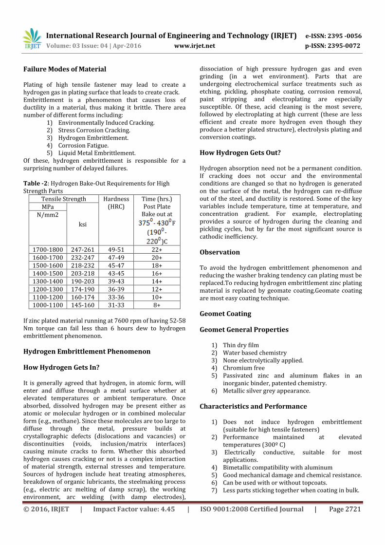
Failure Modes of Material Plating of high tensile fastener may lead to create a hydrogen gas in plating surface that leads to create crack. Embrittlement is a phenomenon that causes loss of ductility in a material, thus making it brittle. There area number of different forms including:
1) Environmentally Induced Cracking. 2) Stress Corrosion Cracking. 3) Hydrogen Embrittlement. 4) Corrosion Fatigue. 5) Liquid Metal Embrittlement.
Of these, hydrogen embrittlement is responsible for a surprising number of delayed failures. Table -2: Hydrogen Bake-Out Requirements for High Strength Parts
Tensile Strength Hardness (HRC)
Time (hrs.) Post Plate
Bake out at
- F
( -
)C
MPa
ksi
N/mm2
1700-1800 247-261 49-51 22+ 1600-1700 232-247 47-49 20+ 1500-1600 218-232 45-47 18+ 1400-1500 203-218 43-45 16+ 1300-1400 190-203 39-43 14+ 1200-1300 174-190 36-39 12+ 1100-1200 160-174 33-36 10+ 1000-1100 145-160 31-33 8+
If zinc plated material running at 7600 rpm of having 52-58 Nm torque can fail less than 6 hours dew to hydrogen embrittlement phenomenon.
Hydrogen Embrittlement Phenomenon
How Hydrogen Gets In?
It is generally agreed that hydrogen, in atomic form, will enter and diffuse through a metal surface whether at elevated temperatures or ambient temperature. Once absorbed, dissolved hydrogen may be present either as atomic or molecular hydrogen or in combined molecular form (e.g., methane). Since these molecules are too large to diffuse through the metal, pressure builds at crystallographic defects (dislocations and vacancies) or discontinuities (voids, inclusion/matrix interfaces) causing minute cracks to form. Whether this absorbed hydrogen causes cracking or not is a complex interaction of material strength, external stresses and temperature. Sources of hydrogen include heat treating atmospheres, breakdown of organic lubricants, the steelmaking process (e.g., electric arc melting of damp scrap), the working environment, arc welding (with damp electrodes),
dissociation of high pressure hydrogen gas and even grinding (in a wet environment). Parts that are undergoing electrochemical surface treatments such as etching, pickling, phosphate coating, corrosion removal, paint stripping and electroplating are especially susceptible. Of these, acid cleaning is the most severe, followed by electroplating at high current (these are less efficient and create more hydrogen even though they produce a better plated structure), electrolysis plating and conversion coatings.
How Hydrogen Gets Out?
Hydrogen absorption need not be a permanent condition. If cracking does not occur and the environmental conditions are changed so that no hydrogen is generated on the surface of the metal, the hydrogen can re-diffuse out of the steel, and ductility is restored. Some of the key variables include temperature, time at temperature, and concentration gradient. For example, electroplating provides a source of hydrogen during the cleaning and pickling cycles, but by far the most significant source is cathodic inefficiency.
Observation To avoid the hydrogen embrittlement phenomenon and reducing the washer braking tendency can plating must be replaced.To reducing hydrogen embrittlement zinc plating material is replaced by geomate coating.Geomate coating are most easy coating technique.
Geomet Coating
Geomet General Properties
1) Thin dry film 2) Water based chemistry 3) None electrolytically applied. 4) Chromium free 5) Passivated zinc and aluminum flakes in an
inorganic binder, patented chemistry. 6) Metallic silver grey appearance.
Characteristics and Performance
1) Does not induce hydrogen embrittlement (suitable for high tensile fasteners)
2) Performance maintained at elevated temperatures (300º C)
3) Electrically conductive, suitable for most applications.
4) Bimetallic compatibility with aluminum 5) Good mechanical damage and chemical resistance. 6) Can be used with or without topcoats. 7) Less parts sticking together when coating in bulk.

International Research Journal of Engineering and Technology (IRJET) e-ISSN: 2395 -0056
Volume: 03 Issue: 04 | Apr-2016 www.irjet.net p-ISSN: 2395-0072
© 2016, IRJET | Impact Factor value: 4.45 | ISO 9001:2008 Certified Journal | Page 2722
Hydrogen Embrittlement Checking Procedure First take a beaker and keep sample parts into it carefully so that parts can’t touch the wall of breaker then, pour Ethylene Glycol into the breaker until the parts totally immersedin the Ethylene Glycol solution. Then switch on the fume hood chamber and put the beaker at the heater and heat it until the temperature reaches upto . As temp reaches off the heater and take the beaker out of the fume heater and check sample part. If any bubble forming on the washer surface then it is fail and if not form bubble then it is ok.
Hardness Testing Result Table -3: Hardness testing result
Sr No
Parameter Specificati
on
Observation Zinc
Plating Geomate Coating
1 Chemical
Composition
C60 - -
2 Hardness 40-48 HRC 40.5-41.1
HRC 43.7-44.1
HRC
3 Micro-
structure Tempered Martensite
Tempered Martensite
Tempered Martensite
3.4.2 Machine In assembly there are six parts on crank shaft transmission side.All contributing parts behind washer if any part is having less accuracy than prescribed then surface contact of washer to claw coupling may change.The Machining process is done on claw coupling if surface of claw coupling not finished properly that can lead to creating gap between the washer and claw coupling.Due to this possibility gap analysis done by using software.
Analysis Stages
Washer failure analysis is done by using HYPERMESH soft. Checking different condition for detecting washer failure.Analysis is by two different conditions by keeping load constant and by keeping % of contact surface area constant.Condition 1:52 Nm constant torque increasing % of contact surface area.Condition 2: % of fixed surface constant increasing torque.
High Tensile Fastener Assembly
Fig -4: High tensile fastener figure
Contact Surface Area Analysis Analysis Condition:- 52 N-m Torque & 10 % Contact Surface Area
Fig -5: Boundary condition of washer
Fig -6: Displacement of washer
Fig -7: Stresses in washer
International Research Journal of Engineering and Technology (IRJET) e-ISSN: 2395 -0056
Volume: 03 Issue: 04 | Apr-2016 www.irjet.net p-ISSN: 2395-0072
© 2016, IRJET | Impact Factor value: 4.45 | ISO 9001:2008 Certified Journal | Page 2723
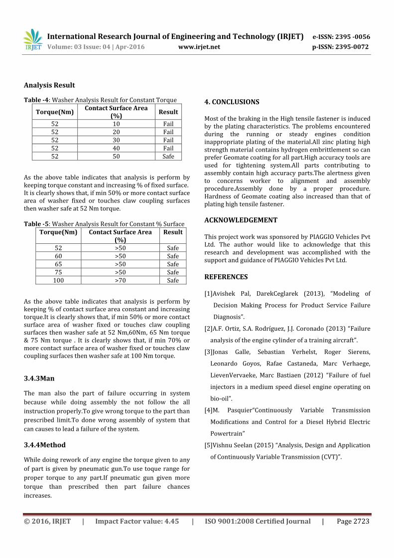
Analysis Result
Table -4: Washer Analysis Result for Constant Torque
Torque(Nm) Contact Surface Area
(%) Result
52 10 Fail 52 20 Fail 52 30 Fail 52 40 Fail 52 50 Safe
As the above table indicates that analysis is perform by keeping torque constant and increasing % of fixed surface. It is clearly shows that, if min 50% or more contact surface area of washer fixed or touches claw coupling surfaces then washer safe at 52 Nm torque.
Table -5: Washer Analysis Result for Constant % Surface
Torque(Nm) Contact Surface Area (%)
Result
52 >50 Safe 60 >50 Safe 65 >50 Safe 75 >50 Safe
100 >70 Safe
As the above table indicates that analysis is perform by keeping % of contact surface area constant and increasing torque.It is clearly shows that, if min 50% or more contact surface area of washer fixed or touches claw coupling surfaces then washer safe at 52 Nm,60Nm, 65 Nm torque & 75 Nm torque . It is clearly shows that, if min 70% or more contact surface area of washer fixed or touches claw coupling surfaces then washer safe at 100 Nm torque.
3.4.3Man
The man also the part of failure occurring in system
because while doing assembly the not follow the all
instruction properly.To give wrong torque to the part than
prescribed limit.To done wrong assembly of system that
can causes to lead a failure of the system.
3.4.4Method
While doing rework of any engine the torque given to any
of part is given by pneumatic gun.To use toque range for
proper torque to any part.If pneumatic gun given more
torque than prescribed then part failure chances
increases.
4. CONCLUSIONS Most of the braking in the High tensile fastener is induced by the plating characteristics. The problems encountered during the running or steady engines condition inappropriate plating of the material.All zinc plating high strength material contains hydrogen embrittlement so can prefer Geomate coating for all part.High accuracy tools are used for tightening system.All parts contributing to assembly contain high accuracy parts.The alertness given to concerns worker to alignment and assembly procedure.Assembly done by a proper procedure. Hardness of Geomate coating also increased than that of plating high tensile fastener.
ACKNOWLEDGEMENT This project work was sponsored by PIAGGIO Vehicles Pvt Ltd. The author would like to acknowledge that this research and development was accomplished with the support and guidance of PIAGGIO Vehicles Pvt Ltd.
REFERENCES [1]Avishek Pal, DarekCeglarek (2013), “Modeling of
Decision Making Process for Product Service Failure
Diagnosis”.
[2]A.F. Ortiz, S.A. Rodríguez, J.J. Coronado (2013) “Failure
analysis of the engine cylinder of a training aircraft”.
[3]Jonas Galle, Sebastian Verhelst, Roger Sierens,
Leonardo Goyos, Rafae Castaneda, Marc Verhaege,
LievenVervaeke, Marc Bastiaen (2012) “Failure of fuel
injectors in a medium speed diesel engine operating on
bio-oil”.
[4]M. Pasquier“Continuously Variable Transmission
Modifications and Control for a Diesel Hybrid Electric
Powertrain”
[5]Vishnu Seelan (2015) “Analysis, Design and Application
of Continuously Variable Transmission (CVT)”.