failure analysis of small composite sandwich turbine … · the composite sandwich blade is then...
TRANSCRIPT

Available online at www.sciencedirect.com
The Twelfth East Asia-Pacific Conference on Structural Engineering and Construction
Failure Analysis of Small Composite Sandwich Turbine Blade Subjected to Extreme Wind Load
C. P. Chen and T. Y. Kam* Mechanical Engineering Department, National Chiao Tung University, Taiwan
Abstract
In this paper, the progressive failure process of composite sandwich wind turbine blades subjected to wind load is studied via both theoretical and experimental approaches. In the theoretical study, the wind pressure acted on the wind blade surface is estimated in an aerodynamic analysis. The stresses in the wind blade are determined using the finite element code ANSYS in which the skin and the core of the blade are modeled using shell and solid elements, respectively. A phenomenological failure criterion is adopted to predict the first-ply failure strength of the blade. After the occurrence of the initial failure, the material properties at the failure locations are modified following a material degradation rule. The updated stiffness matrix of the blade is then obtained with the consideration of the changes of the material properties and configuration of the blade. An incremental load approach together with a sequential stiffness adjustment technique is used to trace the load-displacement curve and thus determine the ultimate strength of the blade. In the experimental investigation, a composite sandwich wind blade was fabricated for strength testing. In the test, the Whiffle-tree approach was used to simulate the wind load on the blade. The measured ultimate load of the wind blade was then used to validate the accuracy of the proposed method for failure analysis of composite sandwich wind blades. © 2011 Published by Elsevier Ltd. Selection and/or peer-review under responsibility of [name organizer] Keywords: Wind energy, wind turbine blade, composite materials, failure analysis, sandwich structure.
1. INTRODUCTION
Recently, wind energy has become one of the most important renewable energy sources. In a horizontal axis wind power system, turbine blades are used to convert wind energy to electricity. In general, turbine blades are required to be light and have small mass moment of inertia so that they can start to rotate at low wind speed. On the other hand, a wind power system has to survive severe environment for at least 20 years. During its lifetime, a wind blade may experience strong wind with
1877–7058 © 2011 Published by Elsevier Ltd.doi:10.1016/j.proeng.2011.07.248
Procedia Engineering 14 (2011) 1973–1981

1974 C.P. Chen and T.Y. Kam / Procedia Engineering 14 (2011) 1973–1981
speed as high as 60m/s and in such condition, the blade should have enough strength to sustain the extreme wind load. In view of these requirements, the reliability of wind turbine blade has become an important topic of research. Recently, many papers have been devoted to the study of different aspects of wind turbine blades including structural analysis, testing, and prediction of wind load. For instance, Overgaard et al (2010a, b) studied the structural collapse of a wind turbine blade via both theoretical and experimental approaches. Otero and Ponta (2010) performed the structural analysis of wind turbine blades using a generalized Timoshenko beam model. In this paper, the development process of a composite sandwich blade for a 1kW wind turbine is presented. A method established on the basis of the finite element method and a failure criterion is proposed for the progressive failure of a composite sandwich wind blade. The first-ply failure load as well as the ultimate load of the wind blade is determined using the proposed method.
2. WIND BLADE CHARACTERISTICS
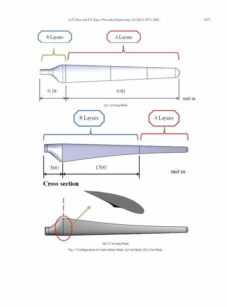
The strengths of two types of composite sandwich wind blades with lengths of 1 and 2.5m will be analyzed in this study. The shapes and dimensions of the composite sandwich wind blades are shown in Fig. 1. The skin and core of the wind blade are made of Glass fabric/epoxy composite laminae and PVC foam, respectively. The skin at different regions of the blade has different numbers of layers. As shown, for the 1m long blade, the layer numbers are 4 and 8 in regions 1 and 2, respectively, while those for the 2.5m one are 4, 6, and 8 for regions 1, 2, and 3, respectively. The handle at the blade root is made of aluminum alloy, which is used as a joint for connecting the blade to the electricity generator. The blade is fabricated via a VRTM approach. The mold used to make the PVC foam core is shown in Fig. 2. The foam core is wrapped by glass fabric as shown in Fig. 3. After placing the glass fabric wrapped core in the steel mold as shown in Fig. 4, epoxy resin is injected into the mold via 3 holes in the mold. The injection holes are chosen in such a way that epoxy resin can be distributed uniformly on the glass fabric of the blade. During the resin injection process, the air in the mold is vacuumed to assist the flow of the resin in the mold. The composite sandwich blade is then cured under room temperature for 4 hours. The cured 1m wind blade is shown in Fig. 5. The wind loads acting on an airfoil is shown schematically in Fig. 6 in which Uo is incoming wind speed, rotational speed of blade, W relative wind speed, P twisting angle, angle of attack, pitch angle, C airfoil cord length, L lifting force, D drag force, and Q resultant force. T and q are force components in x and y directions, respectively. The differential lifting ( Lr) and drag ( Dr) forces acting on a differential area S of the blade are determined from the following equations.
SCWL Lr25.0 (1)
SCWD Dr25.0 (2)
where is air mass density, W relative wind speed, CL lifting coefficient, and CD drag coefficient.Using the above equations, the distribution of wind load on the blade can be estimated.
3. FINITE ELEMENT ANALYSIS
Detailed finite element analyses of the composite wind blades using the finite element code ANSYS, a failure criterion, and an incremental load procedure have been performed to study the progressive failure behaviors of the blade. In the finite element model of the composite wind blade, the skin is modeled using SHELL99 elements while the core using SOLID185 elements. The finite element model of the blade is shown in Fig. 7. The maximum stress failure criterion is used to identify the failure locations in the wind
C.P. Chen and T.Y. Kam / Procedia Engineering 14 (2011) 1973–1981 1975
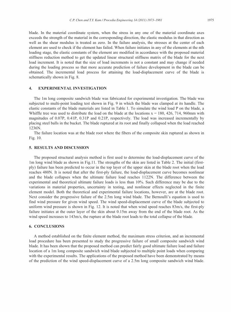
blade. In the material coordinate system, when the stress in any one of the material coordinate axes exceeds the strength of the material in the corresponding direction, the elastic modulus in that direction as well as the shear modulus is treated as zero. In the failure analysis, the stresses at the center of each element are used to check if the element has failed. When failure initiates in any of the elements at the nth loading stage, the elastic constants of the element are modified in accordance with the proposed material stiffness reduction method to get the updated linear structural stiffness matrix of the blade for the next load increment. It is noted that the size of load increments is not a constant and may change if needed during the loading process so that more accurate prediction of failure development in the blade can be obtained. The incremental load process for attaining the load-displacement curve of the blade is schematically shown in Fig. 8.
4. EXPERIMENTAL INVESTIGATION
The 1m long composite sandwich blade was fabricated for experimental investigation. The blade was subjected to multi-point loading test shown in Fig. 9 in which the blade was clamped at its handle. The elastic constants of the blade materials are listed in Table 1. To simulate the wind load P on the blade, a Whiffle tree was used to distribute the load on the blade at the locations x = 180, 426, 714, 960mm with magnitudes of 0.07P, 0.41P, 0.31P and 0.21P, respectively. The load was increased incrementally by placing steel balls in the bucket. The blade ruptured at its root and finally collapsed when the load reached 1236N.
The failure location was at the blade root where the fibers of the composite skin ruptured as shown in Fig. 10.
5. RESULTS AND DISCUSSION
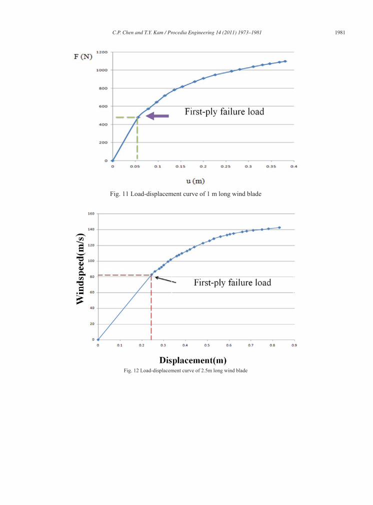
The proposed structural analysis method is first used to determine the load-displacement curve of the 1m long wind blade as shown in Fig.11. The strengths of the skin are listed in Table 2. The initial (first-ply) failure has been predicted to occur in the top layer of the upper skin at the blade root when the load reaches 480N. It is noted that after the first-ply failure, the load-displacement curve becomes nonlinear and the blade collapses when the ultimate failure load reaches 1122N. The difference between the experimental and theoretical ultimate failure loads is less than 10%. Such difference may be due to the variations in material properties, uncertainty in testing, and nonlinear effects neglected in the finite element model. Both the theoretical and experimental failure locations, however, are at the blade root. Next consider the progressive failure of the 2.5m long wind blade. The Bernoulli’s equation is used to find wind pressure for given wind speed. The wind speed-displacement curve of the blade subjected to uniform wind pressure is shown in Fig. 12. It is noted that when wind speed reaches 83m/s, the first-ply failure initiates at the outer layer of the skin about 0.15m away from the end of the blade root. As the wind speed increases to 143m/s, the rupture at the blade root leads to the total collapse of the blade.
6. CONCLUSIONS
A method established on the finite element method, the maximum stress criterion, and an incremental load procedure has been presented to study the progressive failure of small composite sandwich wind blade. It has been shown that the proposed method can predict fairly good ultimate failure load and failure location of a 1m long composite sandwich wind blade subjected to multiple point loads when comparing with the experimental results. The applications of the proposed method have been demonstrated by means of the prediction of the wind speed-displacement curve of a 2.5m long composite sandwich wind blade.

1976 C.P. Chen and T.Y. Kam / Procedia Engineering 14 (2011) 1973–1981
From the predicted wind speed-displacement curve, the first-ply and ultimate failure wind speeds as well as the failure location can be easily identified. The results produced by the proposed method should be useful for the reliability design of composite sandwich wind blades.
Acknowledgements
This research work was supported by the National Science Council under grant number NSC 99-2623-E-009-001-ET.
References
[1] Overgaard, LCT, Lund, E, and Thomsen, OT (2010). Structural collapse of a wind turbine blade. Part A: Static test and equivalent single layered models, Composites Part A-Applied Science and Manufacturing, Vol. 41 (2), pp. 257-270.
[2] Overgaard, LCT and Lund, E (2010). Structural collapse of a wind turbine blade. Part B: Progressive interlaminar failure models, Composites Part A-Applied Science and Manufacturing, Vol. 1 (2), pp. 271-283..
[3] Otero, AD and Ponta, FL (2010). Structural analysis of wind turbine blades by a Generalized Timoshenko Beam Model , ASME Journal of Sol. Energy Eng., Vol. 132 (1), 011015
Table 1 Material properties of wind blade
Unit (MKS)
MAT=1 MAT=2 MAT=3 MAT=4
E-glass PS Polystyrene Epoxy Aluminum (6061-T6)
Ex 3.648E+10
1.000E+07 3.226E+09 6.89E+10 Ey 3.648E+10
Ez 3.648E+10
x 0.212
0.3748 0.375 0.35 y 0.212
z 0.212
Gxy 2.637E+09
Gyz 2.637E+09
Gxz 2.637E+09
Table 2. Strengths of Glass/epoxy skin
XT XC YT YC ZT ZC S R
576.44 MPa 601.2 MPa 576.44 MPa 601.2 MPa 576.44 MPa 601.2 MPa 64 MPa 30.17 MPa
C.P. Chen and T.Y. Kam / Procedia Engineering 14 (2011) 1973–1981 1977
(a) 1 m long blade
(b) 2.5 m long blade
Fig. 1 Configuration of wind turbine blade: (a) 1m blade; (b) 2.5m blade.

1978 C.P. Chen and T.Y. Kam / Procedia Engineering 14 (2011) 1973–1981
Fig. 2 Mold for fabricating PVC core Fig. 3 Core wrapped by glass fabric
Fig.4 Steel mold for VRTM Fig. 5 Cured composite wind blade

C.P. Chen and T.Y. Kam / Procedia Engineering 14 (2011) 1973–1981 1979
Fig. 6 Loading condition of airfoil cross-section
Fig. 7 Finite element model of 1 m long wind blade

1980 C.P. Chen and T.Y. Kam / Procedia Engineering 14 (2011) 1973–1981
Fig. 8 Incremental load process
Fig. 9 Multi-point loading test
Fig. 10 Failure of 1 m wind blade
C.P. Chen and T.Y. Kam / Procedia Engineering 14 (2011) 1973–1981 1981
Fig. 11 Load-displacement curve of 1 m long wind blade
Fig. 12 Load-displacement curve of 2.5m long wind blade