fafnir wide inner ring bearings with locking collars · 2 / mounting guide product information the...
TRANSCRIPT

Mounting Guide
®
timken_5734mg.pm65 10/2/03, 7:27 AM51

Mounting Guide / 1
TABLE OF CONTENTSPAGE
Product Information. . . . . . . . . . . . . . . . . . . . . . . . 2-7
Wide Inner Ring bearings . . . . . . . . . . . . . . . 2-3
Housed Units . . . . . . . . . . . . . . . . . . . . . . . . . 4-5
Spherical Roller bearings . . . . . . . . . . . . . . . . 6-7
Internal Clearances . . . . . . . . . . . . . . . . . . . . . . . 8-12
Installation of Drawn Cup bearings . . . . . . . . . . . . . 13
How to Inspect a bearing journal
or housing bore . . . . . . . . . . . . . . . . . . . . . . . . . 14-16
Shaft and Housing Fits . . . . . . . . . . . . . . . . . . . 17-39
Shaft Design – Needle bearings . . . . . . . . . . . . . . . 40
Housing Design – Needle bearings . . . . . . . . . . . . 41
Shaft and Housing Shoulders . . . . . . . . . . . . . . 42-44
Tables . . . . . . . . . . . . . . . . . . . . . . . . . . . . . . . . 45-46
Torrington Shaft Mounting Accessories . . . . . . . . . 47
INTRODUCTION
The intent of this mounting guide is to provide theinformation you need to properly mount Timken®
Torrington® ball, roller and needle bearings. For addi-tional assistance please feel free to contact a TimkenAuthorized Distributor or sales office in your area. Foryour nearest Timken sales representative, call (800)223-1954. Outside the U.S. and Canada, call (330)438-3000.
®
Mounting Guide
timken_5734mg.pm65 10/2/03, 7:27 AM1

2 / Mounting Guide
PRODUCT INFORMATION
The Timken® Fafnir® line from The Timken Company originated the wide inner ring bearing design forball bearings which could be easily mounted on straight shafts and positioned without shoulders,locknuts or adapters.
The internal bearing construction is basically the same as the deep race, single row radial type withability to carry radial, thrust and combined loads, while providing low friction qualities which arecharacteristic of high-grade bearings. The inner ring is generally extended on both sides of the race toprovide additional shaft support, and is locked to the shaft by specially designed setscrews or by theTimken-originated, eccentric self-locking collar or concentric collar. The wide inner ring bearings are alsoavailable with cylindrical or spherical outside diameters. The cylindrical or straight O.D. type is used formounting in straight-bored housings. The spherical O.D. type must be mounted in a correspondingspherical seat and is used to compensate for shaft or housing misalignments.
FAFNIR WIDE INNER RING BEARINGS WITH LOCKING COLLARSThe following series are available with the cam (self-locking) collar.
RR SeriesThese bearings feature the flareout, contact type R-seal which encloses a synthetic rubber impregnatedwasher between two metal caps. Most sizes incorporate the Fafnir Shroud-Seal design. R-seal wide innerring bearings are available in the following non-relubricatable variations: KR (one seal, cylindrical O.D.),KRR and KRRB (two seals). Relubricatable versions are: G-KRR, G-KRRB and GN-KRRB (heavy-duty).
RA-RR SeriesThe RA-RR series features an extended inner ring and self-locking collar for simple effective shaft retentionin a standard series bearing. The newly developed, positive contact, land-riding R-seal provides improvedprotection against the heavy contamination encountered in many applications. All sizes have a heatstabilized, moisture conditioned 6/6 nylon retainer which has proven extremely effective under conditions ofmisalignment.RA-RR extended inner ring bearings are available as RA-RR (two-seals, straight O.D. ) and RA-RRB (twoseals, spherical O.D. ). Relubricatable versions are GRA-RR and GRA-RRB.
Tri-Ply-Seal SeriesTri-Ply Seal bearings are designed for environments where severe conditions and moisture are present.The new one piece Tri-Ply seals incorporate a highly effective seal design molded to an exterior shroudcap. The shroud cap protects the seal lips from fiber wrap and abrasion while enhancing the overall sealingeffectiveness of the unit. All units incorporate the self-locking collar and have a nylon retainer.Tri-ply Seal bearings are available in both a non-relubricatable (KPPB) and relubricatable version(G- KPPB).
External Self-Aligning SeriesThe construction of this series permits the inner assembly, which contains an open type ball bearing withspherical O.D. to align in the seat of the mating outer ring. The seat of this outer ring is matched with thespherical O.D. of the ball bearing outer ring providing unrestricted self-alignment which allows the innerassembly to become square and true with the shaft. Self-aligning units are available in both standard SM-Sor heavy SMN-S series.
RA-DD Series BearingsThe new RA-DD series bearings are extended inner ring type with cam locking collars. They incorporatetwo close fitting non-contact grease shields to effectively retain lubricant and provide protection againstharmful contaminants. The non-contact metallic shields provide improved high speed and low torqueperformance such as required for high speed printing press applications. The 6/6 molded nylon retainer hasproven extremely effective under conditions of misalignment. These bearings are dimensionally inter-changable and have the same load capacities as the RA-RR series. (Available in 5⁄8"-1 1⁄2" shaft sizes.)
WIDE INNER RING BEARINGS WITH SETSCREW LOCKING DEVICEThe following series are available with the setscrew locking device with special setscrews that are resistantto loosening during operation.
YA-RR seriesThe (G)YA-RR(B)series relubricatable and non-relubricatable bearings are an extended inner ring type withspecially designed setscrews. Positive contact land-riding R-Seals provide protection against harmfulcontaminants and retain lubricant.Setscrew Series bearings are available in both non-relubricatable version YA-RRB and relubricatableversion GYA-RRB. Both types have nylon retainers.
ER SeriesThis series offers industry standard mounting dimensions and standard nomenclature for a large variety ofsizes of relubricatable, extended inner ring bearings for through-bored housings. All bearings in this serieshave nylon retainers and are equipped with snap rings which eliminate the need for machining housingshoulders.Positive contact landriding R Seals provide protection against harmful contaminants and retain lubricant.ER bearings are all black oxide coated for corrosion resistance.
RR Series
RA-RR Series
Tri-Ply-Seal Series
External Self-Aligning Series
RA-DD Series
YA-RR Series
ER Series
timken_5734mg.pm65 10/2/03, 7:27 AM2
www.bearing.sg
Mounting Guide / 3
PRODUCT INFORMATION
GC-KRRB Series
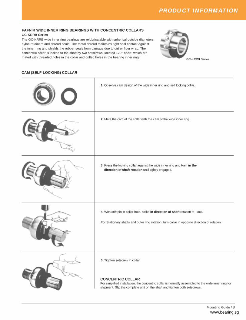
FAFNIR WIDE INNER RING BEARINGS WITH CONCENTRIC COLLARSGC-KRRB SeriesThe GC-KRRB wide inner ring bearings are relubricatable with spherical outside diameters,nylon retainers and shroud seals. The metal shroud maintains tight seal contact againstthe inner ring and shields the rubber seals from damage due to dirt or fiber wrap. Theconcentric collar is locked to the shaft by two setscrews, located 120° apart, which aremated with threaded holes in the collar and drilled holes in the bearing inner ring.
CONCENTRIC COLLARFor simplified installation, the concentric collar is normally assembled to the wide inner ring forshipment. Slip the complete unit on the shaft and tighten both setscrews.
1. Observe cam design of the wide inner ring and self locking collar.
2. Mate the cam of the collar with the cam of the wide inner ring.
3. Press the locking collar against the wide inner ring and turn in the direction of shaft rotation until tightly engaged.
4. With drift pin in collar hole, strike in direction of shaft rotation to lock.
For Stationary shafts and outer ring rotation, turn collar in opposite direction of rotation.
5. Tighten setscrew in collar.
CAM (SELF-LOCKING) COLLAR
timken_5734mg.pm65 10/2/03, 7:27 AM3
www.bearing.sg

4 / Mounting Guide
PRODUCT INFORMATION
Ball Bearing housed units, originated by Timken’s own Fafnir line, areavailable in a wide variety of types and sizes to accomodate acomplete range of operating conditions.
These units generally have cast iron housings and are designed formounting on straight shafts with a slip fit. The self-locking collar andthe setscrew inner bearing designs provide ease in mounting, boltholes in housings take standard bolts for assembling these units tomachinery frames. Several series are also available with the concentriclocking collar.
As most of these units are made with a self aligning feature, it is
unnecessary for the user to refine his design in excess of practicallimits. If desired, units incorporating prelubricated wide inner ringbearings may be furnished without grease fittings.
There are several basic types of housed units available: PillowBlocks, Flanged Cartridges, Flangette Units, Cylindrical Cartridgesand Take-up Units. The type required is generally determined by itsapplication and mounting requirements. Within the basic type selected,numerous variations allow for load factors, shaft sizes, mountingsurface dimensions, base to shaft center line heights and lubricationrequirements.
PILLOW BLOCKS
Pillow blocks, the most commonly used type of mounted units, aredesigned to provide shaft support where the mounting surface isparallel to the shaft axis. The bolt holes are usually slotted foradjustment during mounting.
Pillow blocks are supplied in both standard and heavy duty series.Pressed steel and rubber pillow blocks are also available for light dutyapplications.
FLANGED CARTRIDGES
Flanged cartridges are used where a shaft passes through the machineframe at a right angle. A four bolt mounting is the most common,however, where the mounting area is restricted, three and two boltversions are available. A piloted flanged cartridge, also available,provides additional mounting accuracy and support.
Flanged cartridges are supplied in both standard and heavy dutyseries. Iron and rubber flanged cartridges are also available.
A complete line of Flangette Units, pressed steel flanged cartridges,provides an economical solution to light duty applications. Two, threeand four bolt mountings are available along with a relubricable version.
CYLINDRICAL CARTRIDGES
Cylindrical cartridges, like flanged cartridges, provide shaft supportwhere the shaft axis is perpendicular to and passing through amachined housing which is generally very thick. The outside diameterof the cylindrical cartridges permits mounting with a press fit into astraight, through-bored housing.
Cylindrical cartridges have a machined spherical bearing seat toprovide initial shaft alignment in standard duty applications. Synthetic,conductive rubber cylindrical cartridges are also available for applica-tions where low cost, light duty, low noise operation is essential.
TAKE-UP UNITS
Take-up units are used where shaft adjustment and belt tighteningdevices are required, such as conveyor applications. Frames for take-up units provide for either side or top mounting.
Take-up units are available in cast iron for standard duty andpressed steel for economical, light duty applications.
timken_5734mg.pm65 10/2/03, 7:27 AM4
www.bearing.sg
Mounting Guide / 5
PRODUCT INFORMATION
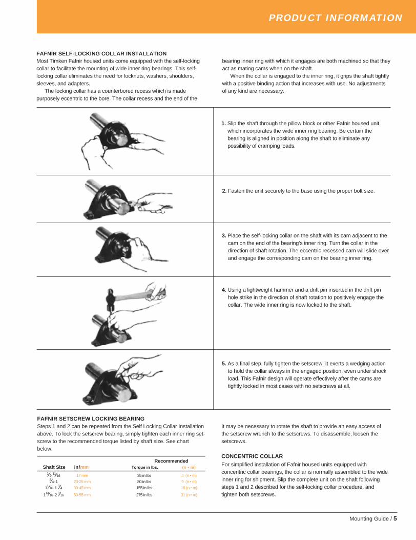
FAFNIR SELF-LOCKING COLLAR INSTALLATIONMost Timken Fafnir housed units come equipped with the self-lockingcollar to facilitate the mounting of wide inner ring bearings. This self-locking collar eliminates the need for locknuts, washers, shoulders,sleeves, and adapters.
The locking collar has a counterbored recess which is madepurposely eccentric to the bore. The collar recess and the end of the
1. Slip the shaft through the pillow block or other Fafnir housed unitwhich incorporates the wide inner ring bearing. Be certain thebearing is aligned in position along the shaft to eliminate anypossibility of cramping loads.
bearing inner ring with which it engages are both machined so that theyact as mating cams when on the shaft.
When the collar is engaged to the inner ring, it grips the shaft tightlywith a positive binding action that increases with use. No adjustmentsof any kind are necessary.
2. Fasten the unit securely to the base using the proper bolt size.
3. Place the self-locking collar on the shaft with its cam adjacent to thecam on the end of the bearing’s inner ring. Turn the collar in thedirection of shaft rotation. The eccentric recessed cam will slide overand engage the corresponding cam on the bearing inner ring.
4. Using a lightweight hammer and a drift pin inserted in the drift pinhole strike in the direction of shaft rotation to positively engage thecollar. The wide inner ring is now locked to the shaft.
5. As a final step, fully tighten the setscrew. It exerts a wedging actionto hold the collar always in the engaged position, even under shockload. This Fafnir design will operate effectively after the cams aretightly locked in most cases with no setscrews at all.
FAFNIR SETSCREW LOCKING BEARINGSteps 1 and 2 can be repeated from the Self Locking Collar Installationabove. To lock the setscrew bearing, simply tighten each inner ring set-screw to the recommended torque listed by shaft size. See chartbelow.
RecommendedShaft Size in/ mm Torque in lbs. (n • m)
1⁄2-11⁄16 17 mm 35 in lbs 4 (n • m)3⁄4 -1 20-25 mm 80 in lbs 9 (n • m)
11⁄16-1 3⁄4 30-45 mm 155 in lbs 18 (n • m)
113⁄16-2 3⁄16 50-55 mm 275 in lbs 31 (n • m)
It may be necessary to rotate the shaft to provide an easy access ofthe setscrew wrench to the setscrews. To disassemble, loosen thesetscrews.
CONCENTRIC COLLAR
For simplified installation of Fafnir housed units equipped withconcentric collar bearings, the collar is normally assembled to the wideinner ring for shipment. Slip the complete unit on the shaft followingsteps 1 and 2 described for the self-locking collar procedure, andtighten both setscrews.
timken_5734mg.pm65 10/2/03, 7:27 AM5

6 / Mounting Guide
PRODUCT INFORMATION
MOUNTING PROCEDURES – TORRINGTON SPHERICALROLLER BEARINGSDepending on the size of bearing and the application, there are differentmethods for mounting rolling bearings. In all methods, however, certain basicrules must be observed.
Cleanliness
Choose a clean environment. Work in an atmosphere free from dust or moisture.If this is not obtainable, and sometimes in the field it isn’t, the installer shouldmake every effort to insure cleanliness by use of protective screens, cleanclothes, etc.
Plan the work
Know in advance what you are going to do and have all necessary tools at hand.This reduces the amount of time for the job and lessens the chance for dirt to getinto the bearing.
Inspection and preparation
All component parts of the machine should be on hand and thoroughly cleanedbefore proceeding. Housings should be cleaned, including blowing out the oilholes. Do not use an air hose on bearings. If blind holes are used, insert amagnetic rod to remove metal chips that might have become lodged there duringfabrication.
Shaft shoulders and spacer rings contacting the bearing should be squarewith the shaft axis. The shaft fillet must be small enough to clear the radius ofthe bearing.
On original installations, all component parts should be checked against thedetail specification prints for dimensional accuracy. Shaft and housing should becarefully checked for size and roundness.
Shaft and housing finish
Shaft surfaces on which the bearing will be mounted must be clean and free fromnicks or burrs. For an application with stationary housing and rotating shaft, it issuggested the bearing seat on the shaft be ground to 63 RMS maximum. If it isimpractical to use a ground finish, a machined finish of 125 RMS is acceptable inmany cases, but the amount of interference fit should be slightly increased.Consult our Engineering Department for recommendations.
For a stationary outer ring which is required to float (i.e. slide axially in thehousing), a housing surface finish of 63 RMS maximum is suggested. Where theouter ring is not required to float, a surface finish of 125 RMS maximum isgenerally satisfactory.
DON’T REMOVE THE BEARING FROM ITS WRAPPERUNTIL ACTUALLY READY TO MOUNT IT.
MOUNTING STRAIGHT BORE BEARINGSHeat expansion method
Most applications require a tight interference fit on the shaft. Mounting issimplified by heating the bearing to expand it sufficiently to slide easily onto theshaft. Two methods of heating are in common use:
1. Tank of heated oil.
2. Induction heating.
The first is accomplished by heating the bearing in a tank of oil having a highflash point. The oil temperature should not be allowed to exceed 250° F. Atemperature of 200°F is sufficient for most applications. The bearing should beheated at this temperature, generally for 20 or 30 minutes, until it is expandedsufficiently to slide onto the shaft very easily.
The induction heating method is particularly suited for mounting smallbearings in production line assembly. Induction heating is rapid, and care mustbe taken to prevent bearing temperature from exceeding 200° F. Trial runs withthe unit and bearing are usually necessary to obtain the proper timing. Thermalcrayons (such as Tempilstics*) which melt at predetermined temperatures can beused to check the bearing temperature.
While the bearing is still hot, it should be positioned squarely against theshoulder. Lockwashers and locknuts, or clamping plates, are then installed tohold the bearing against the shoulder of the shaft. As the bearing cools, thelocknut or clamping plate should be tightened. In cases of outer ring rotation,
where the outer ring is a tight fit in the housing, the housing member can beexpanded by heating.
The oil bath is shown in Figure 1. The bearing should not be in direct contactwith the heat source. The usual arrangement is to have a screen several inchesoff the bottom of the tank. Small support blocks separate the bearing from thescreen. It is important to keep the bearing away from any localized high-heatsource that may raise its temperature excessively, resulting in race hardnessreduction.
Flame-type burners are commonly used. An automatic device for temperaturecontrol is desirable. If safety regulations prevent the use of an open heated oilbath, a mixture of 15% soluble-oil in water may be used. This mixture may beheated to a maximum temperature of about 200° F., without being flammable.The bath should be checked from time to time to insure its proper composition asthe water evaporates. The bath leaves a thin film of oil on the bearing sufficientfor temporary rust prevention, but normal lubrication should be supplied to thebearing as soon as possible after installation. Be sure all of the soluble-oil inwater solution has been drained away from the bearing.
Arbor press methodThe alternative method of mounting, generally used only on smaller sizes, is topress the bearing onto the shaft or into the housing. This can be done by usingan arbor press and a mounting tube as shown in Figure 2. The tube can be ofsoft steel with inside diameter slightly larger than the shaft. The O.D. of the tubeshould not exceed the maximum shoulder height. The tube should be facedsquare at both ends, thoroughly clean inside and out, and long enough to clearthe end of the shaft after the bearing is mounted.
Figure 2:Arbor Press Method
If the outer ring is being pressed into the housing, the O.D. of the mountingtube should be slightly smaller than the housing bore, and the I.D. should not beless than the recommended housing shoulder diameter in the tables ofdimensions.
Coat the shaft with light machine oil to reduce the force needed for the pressfit. Carefully place the bearing on the shaft making sure it is square with the shaftaxis. Apply steady pressure from the arbor ram to drive the bearing firmly againstthe shoulder.
Never attempt to make a press fit on a shaft by applying pressure to theouter ring, or a press fit in a housing by applying pressure to the inner ring.
OIL
BEARING SUPPORTBLOCK
FLAME BURNER
BEARING
BEARING HELDFROM BOTTOMBY SCREEN
* Registered Trademark, Tempil Corp.
Figure 1:Heat Expansion Method
timken_5734mg.pm65 10/2/03, 7:27 AM6

Mounting Guide / 7
PRODUCT INFORMATION
SHAFT MOUNTING TORRINGTON TAPERED BORESPHERICAL ROLLER BEARINGS
Although the fit of a tapered bore spherical roller bearing can bedetermined by measuring the distance the bearing is forced onto thetapered seat, it is more practical to measure the reduction of radialinternal clearance caused by expansion of the inner ring. Thisprocedure requires determining the initial RIC before mounting, andchecking the RIC during mounting until the proper reduction of RIChas been accomplished.
To determine initial RIC, the following procedure should beobserved. A feeler gauge with the thinnest blade of 0.0015" is used.Place the bearing in an upright position with inner and outer ring facesparallel. Place thumbs on the inner ring bore and oscillate inner ringtwo or three times, pressing down firmly. This “seats” the inner ringand rolling elements. Position the individual roller assemblies so that aroller is at the top of the inner ring – on both sides of the bearing.Press the two top rollers inward to assure proper contact with the innerring raceways. With the rollers in correct position, insert a thin blade ofthe feeler gauge between the rollers. Move it carefully over the top
Continue the procedure until the proper amount of reduction isobtained do not exceed recommended amount of reduction. As a finalcheck, make sure that the remaining RIC equals or exceeds theminimum mounted clearance shown on page 10.
During mounting, the RIC should be checked at the unloaded roller.If this happens to be at the bottom, make sure that the roller is raisedto seat firmly on the inboard portion of the inner race.
MOUNTINGAdapters vs. Straight BoreUsually a spherical roller bearing Pillow block assembly is mounted toa straight shaft using a tapered bore bearing and adapter assembly.Standard commercial shafting can be used without additional machin-ing. (Recommended shaft diameters are shown on page 18-21).
Adapter mount also permits maximum flexibility in the axialpositioning of the bearing on the shaft and will accommodate lightlocational thrust loads. Timken® Torrington® pillow blocks for taperedbore and adapter-mounted bearings are available in Series 225, 226,230, 231K and 232K.
Adapter mounted spherical roller bearings require the correctremoval of diametral clearance from the bearing to prevent relativerotation between inner race and sleeve or shaft. Failure to employproper mounting procedures can cause heating and reduced bearingperformance.
When application conditions produce heavy thrust loads or a needexists for exact axial location or a positive shaft interference fit, a directstraight bore mounting may be the best option. This requires ashouldered shaft, machined for proper fit and a straight bore bearing.Torrington pillow block assemblies for straight bore applications areavailable in Series 222, 223, 231, and 232.
Recommended fits for shafts in cylindrical bore spherical rollerbearings are shown on pages 17 through 25. For applications involvingheavy shock, vibration, unbalanced rotating loads or other abnormalconditions, consult your Timken sales associate.
Fixed and Float Pillow BlocksAny style of Torrington pillow blocks can be easily installed either atthe float or fixed position on the shaft. For the fixed position, astabilizing ring is added between the bearing outer ring face and thehousing shoulder to positively locate the shaft and prevent axialmovement.
Some applications require centering of the bearing in its housing.To accomplish this, two special width stabilizing rings can be ordered.
In the float position, the ring is not used allowing the bearing tomove axially (a maximum of 3⁄8") to compensate for thermal expansionor contraction of the shaft.
Pillow blocks ordered by the numbers in the dimensional tables arefixed units. To order float units specify by adding suffix “Float” or “FL”to the pillow block number.
Closed End InstallationsIn some applications, the shaft end is designed to terminate inside thepillow block. For such a design, positive fitting end-closure inserts areavailable to seal out contaminants and retain lubricants. Torringtonheavy-duty end plugs include O-rings for positive sealing.
Designers and installers need to make sure the shaft end does notcontact the closure. A minimum of 1⁄8" clearance at maximum thermalexpansion is recommended between the end of the shaft and theclosure. Dimension “Y” in the product catalog tables defines themaximum permissible length of the shaft from center line of the pillowblock housing. If end closure is desired, specify by adding “CL” (oneend closed) to the pillow block assembly number.
roller, between the roller and outer ring raceway. Repeat this proce-dure, using thicker feeler gauge blades, until one is found that will notgo through. The blade thickness that preceded the “no-go” blade is ameasure of radial internal clearance (RIC) before installation.
Determine the target value of the reduction of RIC following pro-cedure outlined in the example following. Start the mounting procedureby lubricating the tapered shaft with a light coat of machine oil. Slidethe bearing onto the shaft as far as it will go. As the locknut is tight-ened, the interference fit builds up resulting in expansion of the inner ring.Periodically measure the RIC to keep track of the reduction in RIC.
timken_5734mg.pm65 10/2/03, 7:27 AM7

8 / Mounting Guide
LIMITS FOR RADIAL INTERNAL CLEARANCE OF SINGLE ROW, RADIAL CONTACT BALL BEARINGS UNDER NO LOAD(Applies to Bearings of ABEC-1, ABEC-3, ABEC-5, ABEC-7, and ABEC-9 Tolerances)Tolerance Limits in ten-thousandths inches (.0001") and micrometers (µm)
Basic H (2) R (0) P (3) J (4) JJ (5)Bore
Acceptance Limits Acceptance Limits Acceptance Limits Acceptance Limits Acceptance LimitsDiameter
MM
Over Incl. low high low high low high low high low high
2.5 10 0 3 1 5 3 9 6 11 8 150 7 2 13 8 23 14 29 20 37
10 18 0 3.5 1 7 4 10 7 13 10 180 9 3 18 11 25 18 33 25 45
18 24 0 4 2 8 5 11 8 14 11 190 10 5 20 13 28 20 36 28 48
24 30 0.5 4.5 2 8 5 11 9 16 12 211 11 5 20 13 28 23 41 30 53
30 40 0.5 4.5 2 8 6 13 11 18 16 251 11 6 20 15 33 28 46 40 64
40 50 0.5 4.5 2.5 9 7 14 12 20 18 291 11 6 23 18 36 30 51 45 73
50 65 0.5 6 3.5 11 9 17 15 24 22 351 15 8 28 23 43 38 61 55 90
65 80 0.5 6 4 12 10 20 18 28 26 411 15 10 30 25 51 46 71 65 105
80 100 0.5 7 4.5 14 12 23 21 33 30 471 18 12 36 30 58 53 84 75 120
100 120 1 8 6 16 14 26 24 38 35 552 20 15 41 36 66 61 97 90 140
120 140 1 9 7 19 16 32 28 45 41 632 23 18 48 41 81 71 114 105 160
140 160 1 9 7 21 18 36 32 51 47 712 23 18 53 46 91 81 130 120 180
160 180 1 10 8 24 21 40 36 58 53 792 25 20 61 53 102 91 147 135 200
180 200 1 12 10 28 25 46 42 64 59 912 30 25 71 63 117 107 163 150 230
200 240 1 14 12 32 29 54 50 76 72 1053 36 30 81 74 137 127 193 183 267
Continued on the next page
INTERNAL CLEARANCES
FAFNIR RADIAL BALL BEARINGSIn the manufacture of ball bearings, it is standard practice to assemblerings and balls with a specified internal clearance. This characteristic isnecessary to absorb the effect of press fitting the bearing rings atmounting.
Internal clearances sometimes are utilized to compensate forthermal expansion of bearings, shafts and housings or to provide acontact angle in the bearing after mounting.
Internal clearance can be measured either by gauging radially oraxially.
Radial measurement is accepted as the more significant character-istic because it is more directly related to shaft and housing fits. It alsois the method prescribed by the American Bearing ManufacturersAssociation (ABMA).
Radial Internal ClearanceThe radial internal clearance of a radial contact ball bearing can bedefined as the average outer ring raceway diameter minus the averageinner ring raceway diameter minus twice the ball diameter.
Radial internal clearance can be measured mechanically by movingthe outer ring horizontally as pictured in Figure 1. The total movementof the outer ring when the balls are properly seated in the racewaysdetermines the radial internal clearance. Several readings should betaken using different circumferential orientations of the rings in order toget a comprehensive average reading.
Figure 1
A B
timken_5734mg.pm65 10/2/03, 7:27 AM8

Mounting Guide / 9
INTERNAL CLEARANCES
LIMITS FOR RADIAL INTERNAL CLEARANCE OF SINGLE ROW, RADIAL CONTACT BALL BEARINGS UNDER NO LOAD(Applies to Bearings of ABEC-1, ABEC-3, ABEC-5, ABEC-7, and ABEC-9 Tolerances)Tolerance Limits in ten-thousandths inches (.0001") and micrometers (µm)
Basic H (2) R (0) P (3) J (4) JJ (5)
Bore Acceptance Limits Acceptance Limits Acceptance Limits Acceptance Limits Acceptance LimitsDiameter
MM
Over Incl. low high low high low high low high low high
240 280 1 16 13 38 34 62 58 88 84 1223 41 33 97 86 157 147 224 213 310
280 320 2 19 16 45 41 71 67 101 97 1395 48 41 114 104 180 170 257 246 353
320 370 2 21 18 50 46 82 78 116 112 1615 53 46 127 117 208 198 295 284 409
370 430 3 25 22 58 54 95 91 134 130 1878 64 56 147 137 241 231 340 330 475
430 500 4 29 26 67 63 110 106 156 152 21710 74 66 170 160 279 269 396 386 551
500 570 4 32 29 76 72 125 121 177 173 24810 81 74 193 183 318 307 450 439 630
570 640 5 36 33 85 81 140 136 199 195 27813 91 85 216 206 356 345 505 495 706
640 710 8 45 42 94 90 155 151 222 218 30720 114 107 239 229 394 384 564 554 780
710 800 8 55 51 106 102 175 171 248 244 34620 140 130 269 259 445 434 630 620 879
800 1060 11 83 79 139 136 231 227 328 324 45228 211 201 353 345 587 577 833 823 1148
Figure 1
Fafnir radial clearance designations correlate with ABMA symbols asfollows:
FafnirBearingNumber ABMAPrefix Symbol Description
H 2 Snug fit; slight internal clearance; sometimes used to achievea minimum of radial or axial play in an assembly, Example: H204K
R 0 Medium fit; internal clearance generally satisfactory withrecommended shaft and housing fits shown on pages 26-30.Example: RMM204K.
P 3 Loose fit; considerable internal clearance required for applicationsinvolving press fits on both inner and outer rings, extra interferencefits, or temperature differentials. Example: P204K.
J 4 Extra Loose fit; large amount of internal clearance for applicationsinvolving large interference fits or temperature differentials.Example: J204K.
JJ 5 Extra-Extra Loose fit; extra large amount of internal clearance forapplications with large temperature differential and interference fitson both rings.
End play
End play is an alternate method of measuring internal clearance and israrely used except for certain special applications. End play is deter-mined by mounting the bearing, as shown in Figure 2, with one of itsrings clamped to prevent axial movement. A reversing measuring load isapplied to the unclamped ring so that the resultant movement of thatring is parallel to the bearing axis. End play is the total movement of theunclamped ring when the load is applied first in one direction and then inthe other.
When the inner and outer ring raceway curvatures are accuratelyknown, the free end play can readily be calculated from the values ofno load radial clearance by the following formula:
E = √ 4dRD(KO + Ki - 1) - RD2 or ≅ √ 4dRD(KO + Ki - 1)
(Where RD2 is generally a very small value and can be omitted for)most calculations without introducing undue inaccuracy.
E = Free end play where
KO = outer race contour radius expressed as a decimal fraction of theball diameter.
K¡ = inner race contour radius expressed as a decimal fraction of theball diameter
RD = radial clearance (no load)
d = ball diameter
Contact AngleThe contact angle (α) is related to internal clearance as follows:
α = sin-1E( 2 (Ko + Ki - 1 )d )
The contact angle (α) may also be accurately determined in aproduction bearing from its pitch diameter (P.D.) and by measuring thenumber of revolutions (Nc) of the ball and cage assembly relative torotation (Ni) of the inner ring under a light thrust load.
(Nc) = .5Ni(1 – d cos α)P.D.
P.D. Nccos α =d ( 1- .5Ni )
The accuracy of this method of measurement depends greatly uponthe care taken in set-up. Balanced weight for thrust loading, verticaltruing, slow turning, many turns, minimum lubricant of low viscosity andprerotation are all essential for instance. The races should not beradially restrained during the contact angle measurement.
timken_5734mg.pm65 10/2/03, 7:27 AM9

10 / Mounting Guide
TORRINGTON RADIAL SPHERICAL ROLLER BEARINGS
Radial Internal Clearance (RIC) is the radial play within a bearing.Torrington bearing RIC’s allow a tight fit, with sufficient internalclearance after installation for normal operating conditions.
Spherical Roller Bearings with tapered bore (K) require a slightlygreater interference fit on the shaft than would a cylindrical borebearing. The effect of this greater interference fit is a reduction of RIC.For tapered bore bearings, it is critical to select the RIC that allows forthis reduction.
For example, bearing number 22328K C3 (140 mm bore with C3clearance) is to be mounted on a tapered shaft. By feeler gauging,RIC is found to be 0.007" (0.178mm). The chart indicates that theproper fit will be obtained when RIC is reduced by 0.0025" to 0.0035"(0.064 to 0.089 mm). Clearance after mounting is computed: 0.007"-
0.003"= 0.004" (0.178-0.076=0.102mm). The locknut should betightened until RIC reaches 0.004" (0.102mm).
Several factors influence RIC reduction. Inner rings pressed intosolid steel shafts expand approximately 80% of the interference fit.Outer rings pressed into steel or cast iron housings reduce RIC byabout 60%, of the interference fit. For RIC reduction on hollow shaftsor non-steel materials consult Timken sales engineers.
Torrington bearings are supplied with NORMAL RIC, unless other-wise specified. The desired RIC code must be added to the bearingnumber, FOLLOWING ALL OTHER SUFFIXES.
Min./max. values for each RIC are shown in the two adjacentcolumns directly beneath the selected RIC. For example, the minimumvalues shown for C5 are also the maximum values for C4; minimumvalues for C4 are also the maximum values for C3; etc.
INTERNAL CLEARANCES
RADIAL INTERNAL CLEARANCE LIMITSAll data on this page, except Bore I.D. are in inches/millimeters
Cylindrical Bore Tapered Bore
Normal C4 Normal C4 Recommended Recommended(Standard) (Standard) Reduction of RIC RIC after
min. max. min. max. min. max. min. max. Due to Installation Installation (1)
C2 C3 C5 C2 C3 C5
mm min. max. min. max. min. max. min. max. min. max. min. max. min. max. min.
inch inch inch inch inch inch inch inch inch inch inch inch inch inch inchover incl. mm mm mm mm mm mm mm mm mm mm mm mm mm mm mm
24 30 0.0006 0.0010 0.0016 0.0022 0.0030 0.0037 0.0008 0.0012 0.0016 0.0022 0.0030 0.0037 0.0006 0.0008 0.00060.015 0.025 0.040 0.055 0.075 0.095 0.020 0.030 0.040 0.055 0.075 0.095 0.015 0.020 0.015
30 40 0.0006 0.0012 0.0018 0.0024 0.0031 0.0039 0.0010 0.0014 0.0020 0.0026 0.0033 0.0041 0.0008 0.0010 0.00060.015 0.030 0.045 0.060 0.080 0.100 0.025 0.035 0.050 0.065 0.085 0.105 0.020 0.025 0.015
40 50 0.0008 0.0014 0.0022 0.0030 0.0039 0.0049 0.0012 0.0018 0.0024 0.0031 0.0039 0.0051 0.0010 0.0012 0.00080.020 0.035 0.055 0.075 0.100 0.125 0.030 0.045 0.060 0.080 0.100 0.130 0.025 0.030 0.020
50 65 0.0008 0.0016 0.0026 0.0035 0.0047 0.0059 0.0016 0.0022 0.0030 0.0037 0.0047 0.0063 0.0012 0.0015 0.00100.020 0.040 0.065 0.090 0.120 0.150 0.040 0.055 0.075 0.095 0.120 0.160 0.030 0.038 0.025
65 80 0.0012 0.0020 0.0031 0.0043 0.0057 0.0071 0.0020 0.0028 0.0037 0.0047 0.0059 0.0079 0.0015 0.0020 0.00100.030 0.050 0.080 0.110 0.145 0.180 0.050 0.070 0.095 0.120 0.150 0.200 0.038 0.051 0.025
80 100 0.0014 0.0024 0.0039 0.0053 0.0071 0.0089 0.0022 0.0030 0.0043 0.0055 0.0071 0.0091 0.0018 0.0025 0.00140.035 0.060 0.100 0.135 0.180 0.225 0.055 0.080 0.110 0.140 0.180 0.230 0.046 0.064 0.036
100 120 0.0016 0.0030 0.0047 0.0063 0.0083 0.0102 0.0026 0.0039 0.0053 0.0067 0.0087 0.0110 0.0020 0.0028 0.00200.040 0.075 0.120 0.160 0.210 0.260 0.065 0.100 0.135 0.170 0.220 0.280 0.051 0.071 0.051
120 140 0.0020 0.0037 0.0057 0.0075 0.0094 0.0118 0.0031 0.0047 0.0063 0.0079 0.0102 0.0130 0.0025 0.0035 0.00220.050 0.095 0.145 0.190 0.240 0.300 0.080 0.120 0.160 0.200 0.260 0.330 0.064 0.089 0.056
140 160 0.0024 0.0043 0.0067 0.0087 0.0110 0.0138 0.0035 0.0051 0.0071 0.0091 0.0118 0.0150 0.0030 0.0040 0.00220.060 0.110 0.170 0.220 0.280 0.350 0.090 0.130 0.180 0.230 0.300 0.380 0.076 0.102 0.056
160 180 0.0026 0.0047 0.0071 0.0094 0.0122 0.0154 0.0039 0.0055 0.0079 0.0102 0.0134 0.0169 0.0030 0.0045 0.00240.065 0.120 0.180 0.240 0.310 0.390 0.100 0.140 0.200 0.260 0.340 0.430 0.076 0.114 0.061
180 200 0.0028 0.0051 0.0079 0.0102 0.0134 0.0169 0.0043 0.0063 0.0087 0.0114 0.0146 0.0185 0.0035 0.0050 0.00280.070 0.130 0.200 0.260 0.340 0.430 0.110 0.160 0.220 0.290 0.370 0.470 0.089 0.127 0.071
200 225 0.0031 0.0055 0.0087 0.0114 0.0150 0.0185 0.0047 0.0071 0.0098 0.0126 0.0161 0.0205 0.0040 0.0055 0.00300.080 0.140 0.220 0.290 0.380 0.470 0.120 0.180 0.250 0.320 0.410 0.520 0.102 0.140 0.076
225 250 0.0035 0.0059 0.0094 0.0126 0.0165 0.0205 0.0055 0.0079 0.0106 0.0138 0.0177 0.0224 0.0045 0.0060 0.00350.090 0.150 0.240 0.320 0.420 0.520 0.140 0.200 0.270 0.350 0.450 0.570 0.114 0.152 0.089
250 280 0.0039 0.0067 0.0102 0.0138 0.0181 0.0224 0.0059 0.0087 0.0118 0.0154 0.0193 0.0244 0.0045 0.0065 0.00400.100 0.170 0.260 0.350 0.460 0.570 0.150 0.220 0.300 0.390 0.490 0.620 0.114 0.165 0.102
280 315 0.0043 0.0075 0.0110 0.0146 0.0197 0.0248 0.0067 0.0094 0.0130 0.0169 0.0213 0.0268 0.0050 0.0070 0.00400.110 0.190 0.280 0.370 0.500 0.630 0.170 0.240 0.330 0.430 0.540 0.680 0.127 0.178 0.102
315 355 0.0047 0.0079 0.0122 0.0161 0.0217 0.0272 0.0075 0.0106 0.0142 0.0185 0.0232 0.0291 0.055 0.0075 0.00450.120 0.200 0.310 0.410 0.550 0.690 0.190 0.270 0.360 0.470 0.590 0.740 0.140 0.190 0.114
355 400 0.0051 0.0087 0.0134 0.0177 0.0236 0.0295 0.0083 0.0118 0.0157 0.0205 0.0256 0.0323 0.0060 0.0080 0.00500.130 0.220 0.340 0.450 0.600 0.750 0.210 0.300 0.400 0.520 0.650 0.820 0.152 0.203 0.127
Bore(nominal)
(1)For bearings with normal initial clearance Continued on the next page
timken_5734mg.pm65 10/2/03, 7:27 AM10

Mounting Guide / 11
INTERNAL CLEARANCES
TORRINGTON RADIAL SPHERICAL ROLLER BEARINGS (continued)Min./Max. values for each RIC are shown in the two adjacent columns directly beneath the selected RIC. Each single column represents a boundary between adjacentRIC’s. For example, the minimum values shown for C5 are also the maximum values for C4 ; minimum values for C4 are also the maimum values for C3; etc.
Min./Max. values for each RIC are shown in the two adjacent columns directly beneath the selected RIC. Each single column represents a boundary betweenadjacent RIC’s. For example, the minimum values shown for R5 are also the maximum values for R4 ; minimum values for R4 are also the maimum values for R3;etc. The desired RIC code (R1, R2, etc.) must be added to the bearing number, FOLLOWING ALL OTHER SUFFIXES.
RADIAL INTERNAL CLEARANCE LIMITSAll data on this chart are in inches/millimeters.
Bore R2 R4 Bore R2 R4
(nominal) min. max. min. max (nominal) min. max. min. max
R1 R3 R5 R1 R3 R5
Over Incl. min. max. min. max. min. max. Over Incl. min. max. min. max. min. max.
in. in. in. in. in in. in. in. in. in. in. in. in in. in. in.
mm mm mm mm mm mm mm mm mm mm mm mm mm mm mm mm
3.1496 3.9370 0.0005 0.0016 0.0032 0.0051 0.0077 0.0107 11.8110 13.7795 0.0032 0.0050 0.0078 0.0110 0.0148 0.0190
80 100 0.013 0.041 0.081 0.130 0.196 0.272 300 350 0.081 0.127 0.198 0.279 0.376 0.483
3.9370 4.7244 0.0005 0.0018 0.0036 0.0060 0.0089 0.0122 13.7795 15.7480 0.0042 0.0065 0.0093 0.0125 0.0163 0.0205
100 120 0.013 0.046 0.091 0.152 0.226 0.310 350 400 0.107 0.165 0.236 0.318 0.414 0.521
4.7244 5.5118 0.0009 0.0022 0.0041 0.0067 0.0101 0.0139 15.7480 17.7165 0.0055 0.0080 0.0110 0.0142 0.0180 0.0222
120 140 0.023 0.056 0.104 0.170 0.256 0.353 400 450 0.14 0.203 0.279 0.361 0.457 0.564
5.5118 6.2992 0.0010 0.0026 0.0049 0.0077 0.0112 0.0151 17.7165 19.6850 0.0060 0.0085 0.0115 0.0150 0.0200 0.0254
140 160 0.025 0.066 0.124 0.196 0.284 0.384 450 500 0.152 0.216 0.292 0.381 0.508 0.645
6.2992 7.0866 0.0011 0.0027 0.0052 0.0082 0.0118 0.0158 19.6850 22.0472 0.0065 0.0090 0.0120 0.0160 0.0210 0.0264
160 180 0.028 0.069 0.132 0.208 0.300 0.401 500 560 0.165 0.229 0.305 0.406 0.533 0.671
7.0866 7.8740 0.0014 0.0032 0.0060 0.0092 0.0130 0.0172 22.0472 24.8031 0.0070 0.0100 0.0140 0.0190 0.0240 0.0294
180 200 0.036 0.081 0.152 0.234 0.330 0.437 560 630 0.178 0.254 0.356 0.483 0.610 0.747
7.8740 8.6614 0.0016 0.0034 0.0062 0.0094 0.0132 0.0174 24.8031 27.9528 0.0075 0.0110 0.0150 0.0200 0.0250 0.0304
200 220 0.041 0.086 0.157 0.239 0.335 0.4420 630 710 0.190 0.279 0.381 0.508 0.635 0.772
8.6614 10.2362 0.0022 0.0040 0.0068 0.0100 0.0138 0.018 27.9528 31.4961 0.0085 0.0130 0.0180 0.0230 0.0280 0.0334
220 260 0.056 0.102 0.173 0.254 0.351 0.455 710 800 0.216 0.330 0.457 0.584 0.711 0.848
10.2362 11.8110 0.0024 0.0042 0.0070 0.0102 0.0140 0.0182
260 300 0.061 0.107 0.178 0.259 0.356 0.462
Cylindrical Bore Tapered Bore
Normal C4 Normal C4 Recommended Recommended(Standard) (Standard) Reduction of RIC RIC after
min. max. min. max. min. max. min. max. Due to Installation Installation (1)
C2 C3 C5 C2 C3 C5
mm min. max. min. max. min. max. min. max. min. max. min. max. min. max. min.
inch inch inch inch inch inch inch inch inch inch inch inch inch inch inchover incl. mm mm mm mm mm mm mm mm mm mm mm mm mm mm mm
400 450 0.0055 0.0094 0.0146 0.0197 0.0260 0.0323 0.0091 0.0130 0.0173 0.0224 0.0283 0.0358 0.0065 0.0085 0.00600.140 0.240 0.370 0.500 0.660 0.820 0.230 0.330 0.440 0.570 0.720 0.910 0.165 0.216 0.152
450 500 0.0055 0.0102 0.0161 0.0217 0.0283 0.0354 0.0102 0.0146 0.0193 0.0248 0.0311 0.0394 0.0070 0.0090 0.00650.140 0.260 0.410 0.550 0.720 0.900 0.260 0.370 0.490 0.630 0.790 1.000 0.178 0.229 0.165
500 560 0.0059 0.0110 0.0173 0.0236 0.0307 0.0394 0.0114 0.0161 0.0213 0.0268 0.0343 0.0433 0.0080 0.0100 0.00700.150 0.280 0.440 0.600 0.780 1.000 0.290 0.410 0.540 0.680 0.870 1.100 0.203 0.254 0.178
560 630 0.0067 0.0122 0.0189 0.0256 0.0335 0.0433 0.0126 0.0181 0.0236 0.0299 0.0386 0.0484 0.0090 0.0110 0.00800.170 0.310 0.480 0.650 0.850 1.100 0.320 0.460 0.600 0.760 0.980 1.230 0.229 0.279 0.203
630 710 0.0075 0.0138 0.0209 0.0276 0.0362 0.0469 0.0138 0.0201 0.0264 0.0335 0.0429 0.0535 0.0100 0.0120 0.00800.190 0.350 0.530 0.700 0.920 1.190 0.350 0.510 0.670 0.850 1.090 1.360 0.254 0.305 0.203
710 800 0.0083 0.0154 0.0228 0.0303 0.0398 0.0512 0.0154 0.0224 0.0295 0.0378 0.0480 0.0591 0.0110 0.0140 0.00900.210 0.390 0.580 0.770 1.010 1.300 0.390 0.570 0.750 0.960 1.220 1.500 0.279 0.356 0.229
800 900 0.0091 0.0169 0.0256 0.0339 0.0441 0.0567 0.0173 0.0252 0.0331 0.0421 0.0539 0.0665 0.0120 0.0150 0.01000.230 0.430 0.650 0.860 1.120 1.440 0.440 0.640 0.840 1.070 1.370 1.690 0.305 0.381 0.252
900 1000 0.0102 0.0189 0.0280 0.0366 0.0480 0.0618 0.0193 0.0280 0.0366 0.0469 0.0598 0.0732 0.0140 0.0170 0.01100.260 0.480 0.710 0.930 1.220 1.57 0.490 0.710 0.930 1.190 1.520 1.860 0.356 0.432 0.279
(1)For bearings with normal initial clearance
Bore(nominal)
RADIAL CYLINDRICAL ROLLER BEARINGS
timken_5734mg.pm65 10/2/03, 7:27 AM11

12 / Mounting Guide
INTERNAL CLEARANCES
TORRINGTON RADIAL TAPERED ROLLER BEARINGS –TWO ROWIn two row tapered roller bearings, Internal Clearance is usuallydefined as Lateral Clearance (LC) or end play, which is related toRadial Internal Clearance (RIC) by the formula:
LC = RIC X K 0.39
K being a thrust factor which is different for every bearing and isincluded in the table of dimensions.
LC is determined by the relative axial position of cup and cone, andis a function of spacer width in the two element member (cup or cone).In the illustration, the cups shown in black are positioned for zero RIC,allowing no end play. The cups shown in green provide lateralclearance equal to (B-A).
The desired LC must be specified by adding designation codesG1, G2, etc. to the bearing number, FOLLOWING ALL OTHERSUFFIXES.
Bore Nominal Clearance (L C) Tolerance: ±0.001 inch ( ±0.025 mm)
Over Incl. G1 G2 G3 G4 G5 G6 G7 G8 G9
in. in. in. in. in. in. in. in. in. in. in.mm mm mm mm mm mm mm mm mm mm mm
7.5000 12.0000 0.006 0.009 0.018 0.021 0.024 0.027 0.030 0.033 0.036190.500 304.800 0.15 0.23 0.46 0.53 0.61 0.69 0.76 0.84 0.91
12.0000 24.0000 0.007 0.018 0.021 0.024 0.027 0.030 0.034 0.040 0.046304.800 609.600 0.18 0.46 0.53 0.61 0.69 0.76 0.86 1.02 1.17
24.0000 36.0000 0.019 0.023 0.027 0.031 0.035 0.039 0.042 0.046 0.050609.600 914.400 0.48 0.58 0.69 0.79 0.89 0.99 1.07 1.17 1.27
timken_5734mg.pm65 10/2/03, 7:27 AM12

Mounting Guide / 13
INSTALLATION OF TORRINGTON DRAWN CUP BEARINGS
INSTALLATION PROCEDURESA drawn cup bearing must be pressed into its housing. An installationtool similar to the one illustrated must be used in conjunction with astandard press.
It is advisable to utilize a positive stop on the press tool to locate thebearing properly in the housing. The assembly tool should have aleader or pilot, as shown, to aid in starting the bearing true in thehousing.
The installation tool must be coaxial with the housing bore. The balldetent shown on the drawing is used to assist in aligning the rollers of afull complement bearing during installation and to hold the bearing onthe installation tool.
Assemble the bearing with the marked end (the end with identificationmarkings) against the angled shoulder of the pressing tool.
Never hammer the bearing into its housing even in conjunction withthe proper assembly mandrel.
Never press the bearing tightly against a shoulder in the housing. If itis necessary to use a shouldered housing, the depth of the housing boremust be sufficient to ensure the housing shoulder fillet, as well as theshoulder face, clears the bearing.
To remove a drawn cup bearing from a through-bored housing, usea tool similar to the installation tool illustrated, but without the stop. Forsuggested methods of removing bearings from blind and shoulderedbores, consult your Timken sales associate.
A– 1⁄64" (0.4 mm) less than housing boreB– .003" (0.08 mm) less than shaft diameterC– distance bearing will be inset into housing, minimum of .008" (0.2 mm)D– pilot length should be length of bearing less 1⁄32" (0.8 mm)E– approximately 1⁄2 D
C
15°
A
D
E
B
Marked endof bearing
Generous chamferor rounding foreasy bearinginstallation
timken_5734mg.pm65 10/2/03, 7:27 AM13

14 / Mounting Guide
HOW TO INSPECT A BEARING JOURNAL ORHOUSING BORE
A twelve-point inspection is recommended to properly inspect abearing journal or housing bore. Verification of mating componentgeometry is achieved by comparing the inspection measurements tothe recommended (mating component) tolerance limits. Shaft andhousing limits are selected using specific application criteria. Tablesof these limits are published in The Timken Service Catalog, orderno. 5731.
Diameter (size), roundness and taper (form) can be confirmed afterthe twelve measurements are recorded.
THE TWELVE-POINT MEASUREMENT PROCEDURE:
1) Use two-point gauges that are accurate to .0001". It is recom-mended that gauges with accuracy to 1⁄10 of the units that arebeing inspected to be used (resolution to .00001"). We recognizereadily available gauges read to .0001", however.
2) Measure four position at 0°, 45°, 90°, and 135° in three differentplanes of the mating surface (that is in direct contact with thebearing). The three planes should be evenly spaced across thecontact area. The outboard measurements should be 1⁄8” to 1⁄2” infrom each end.
3) Record the measurements on a chart like the one listed below.Keep all three sets of measurements oriented with respect toeach other. Take an average of each plane.
0° 45° 90° 135° AVERAGES
PLANE A A =
PLANE B B =
PLANE C C =
DIAMETER (SIZE) EVALUATION:Compare the average diameter measurement (A, B, C) to the recom-mended tolerance limits. Each average diameter should be within therecommended limits. The mating component diameter is out ofspecification if any average is over or under the recommended limits.
ROUNDNESS (FORM) EVALUATION:Compare the individual measurements in a lane to each other. Themaximum permissible deviation of these measurements is one-half (1⁄2)of the recommended limit. An out-of-round condition exists if differ-ences greater than one-half (1⁄2) of the limit are found.
A B C
0°
45°
90°
135°
HOW TO INSPECT A JOURNAL OR BORE
timken_5734mg.pm65 10/2/03, 7:27 AM14

Mounting Guide / 15
HOW TO INSPECT A JOURNAL OR BORE
TWELVE POINT MEASUREMENT WORKSHEET
Application: Machine:
Comments:
Shaft Tolerances Required: Max: Min: 1⁄2 Limit:
Housing Tolerances Required: Max: Min: 1⁄2 Limit:
0° 45° 90° 135° AVERAGES
PLANE A A =
PLANE B B =
PLANE C C =
DIAMETER (SIZE) EVALUATION:
Compare the average diameter measurement (A, B, C) to therecommended tolerance limits. Each average diameter should bewithin the recommended limits. The mating component diameter is outof specification if any average is over or under the recommendedlimits.
ROUNDNESS (FORM) EVALUATION:
Compare the individual measurements in a plane to each other. Themaximum permissible deviation of these measurements is one-half(1⁄2) of the recommended limit. An out-of-round condition exists ifdifferences greater than one-half (1⁄2) of the limit are found.
TAPER (FORM) EVALUATION:Taper is determined by taking the difference between the plane averages as follows:
AVERAGE A = AVERAGE B = AVERAGE A =
– AVERAGE B = – AVERAGE C = – AVERAGE C =
DIFFERENCE = DIFFERENCE = DIFFERENCE =
Excessive taper exists if the resultant differences exceed one-half (1⁄2) of the specified tolerance range.
SURFACE FINISH REFERENCE:
• Common surface finishes required for shafts are:
≤ 2" diameter = 32rms Micro Finish maximum
> 2" diameter = 63rms Micro Finish maximum
• Common surface finishes required for housings are:Stationary outer ring required to float = 63rms maximumStationary outer ring not required to float = 125rms maximum
MEASUREMENTS (gauges accurate to .0001" minimum is recommended)
timken_5734mg.pm65 10/2/03, 7:27 AM15

16 / Mounting Guide
EXAMPLE:
A 22324YMW33W800C4 “shaker screen” bearing housing inspection.This application requires a “P6” housing tolerance limit. The “P6”housing diameters are 10.2331"/ 10.2343".
Size is verified when the housing “plane” average diameters arebetween 10.2331" and 10.2343".
Roundness and taper inspections require that one-half (1⁄2) of thepermissible tolerance limits be calculated. Thus,
10.2343" .0012" = .0006"-10.2331" AND 2
.0012" maximum limit
Roundness is verified by comparing the differences of the fourmeasurements of a given plane. No difference should exceed .0006".
Taper is verified by comparing the differences of the three averages.No difference should exceed .0006".
CONCLUDING COMMENTS:
Precision ground anti-friction, rolling element bearings are extremelyprecise and refined industrial products. Their performance and life canbe greatly enhanced by the following:
• The working environment must be clean during installation.
• Accepted care, handling techniques, and tools and fixtures must beemployed during removal and installation of bearings during repair.
• Mating component geometry and material should meet industrystandards as published in The Timken Service Catalog.
• Common surface finishes required for shafts are:
≤ 2" diameter = 32rms Micro Finish maximum
> 2" diameter = 63rms Micro Finish maximum
• Common surface finishes required for housings are:Stationary outer ring required to float = 63rms maximumStationary outer ring not required to float = 125rms maximum
HOW TO INSPECT A JOURNAL OR BORE
timken_5734mg.pm65 10/2/03, 7:27 AM16
Mounting Guide / 17
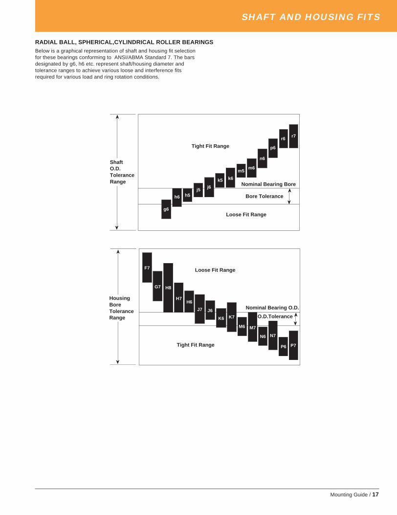
RADIAL BALL, SPHERICAL,CYLINDRICAL ROLLER BEARINGSBelow is a graphical representation of shaft and housing fit selectionfor these bearings conforming to ANSI/ABMA Standard 7. The barsdesignated by g6, h6 etc. represent shaft/housing diameter andtolerance ranges to achieve various loose and interference fitsrequired for various load and ring rotation conditions.
SHAFT AND HOUSING FITS
ShaftO.D.ToleranceRange
Tight Fit Range
Nominal Bearing Bore
Bore Tolerance
Loose Fit Rangeg6
h6 h5j5 j6
k5 k6
m5m6
n6
p6
r6 r7
F7
G7 H8
H7H6
J7 J6
K6 K7
M6 M7
N6 N7
P7P6Tight Fit Range
Loose Fit Range
Nominal Bearing O.D.
O.D.Tolerance
HousingBoreToleranceRange
➤
➤
➤
➤
➤
➤
➤
➤
timken_5734mg.pm65 10/2/03, 7:27 AM17

18 / Mounting Guide
SHAFT AND HOUSING FITS
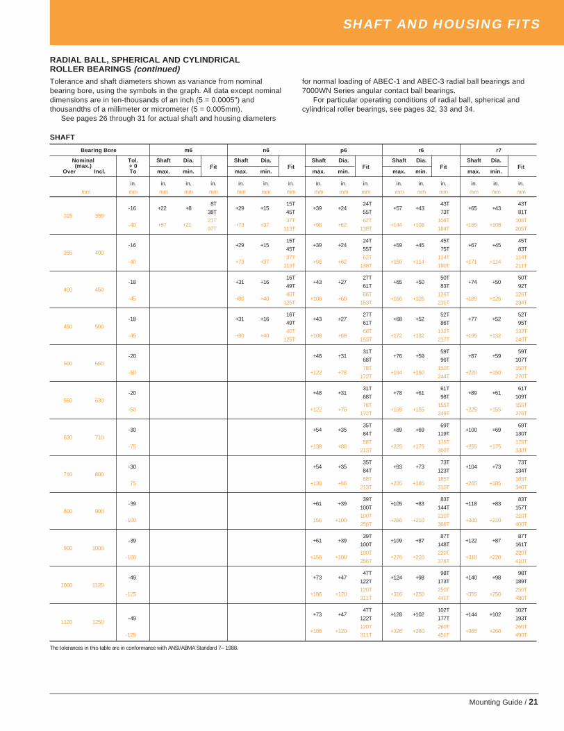
RADIAL BALL, SPHERICAL AND CYLINDRICALROLLER BEARINGSTolerance and shaft diameters shown as variance from nominalbearing bore, using the symbols in the graph. All data except nominaldimensions are in ten-thousands of an inch (5 = 0.0005") and thou-sandths of a millimeter or micrometer (5 = 0.005mm).
See pages 26 through 31 for actual shaft and housing diameters fornormal loading of ABEC-1 and ABEC-3 radial ball bearings and7000WN Series angular contact ball bearings.
For particular operating conditions of radial ball, spherical andcylindrical roller bearings, see pages 32, 33 and 34.
SHAFT
Bearing Bore g6 h6 h5 j5 j6 k5 k6 m5
Nominal Tol. Shaft Dia. Shaft Dia. Shaft Dia. Shaft Dia. Shaft Dia. Shaft Dia. Shaft Dia. Shaft Dia.(max.) +0
Over Incl. To max. min.Fit
max. min.Fit
max. min.Fit
max. min.Fit
max. min.Fit
max. min.Fit
max. min.Fit
max. min.Fit
in. in. in. in. in. in. in. in. in. in. in. in. in. in. in. in. in. in. in. in. in. in. in. in. in.mm mm mm mm mm mm mm mm mm mm mm mm mm mm mm mm mm mm mm mm mm mm mm mm mm mm
5L 3L 2L 1L 1L 0T 2T-3 -2 -5
1T0 -3
3T0 -2
3T+1 -1
4T+2 -1
5T +2 +0 5T+4 +2
7T3 6
12L 8L 5L 2L 2L 1T 4T-8 -4 -12
4T0 -8
8T0 -5
8T+3 -2
11T+6 -2
14T+6 +1
14T+9 +4
17T
6L 4L 2L 1L 1L 0T 2T
6 10-3 -2 -6
1T0 -4
3T0 -2
3T+2 -1
5T+3 -1
6T +3 +0 6T+5 +2
8T14L 9L 6L 2L 2L 1T 6T
-8 -5 -143T
0 -98T
0 -68T
+4 -212T
+7 -215T +7 +1 15T
+12 +620T
7L 4L 3L 1L 1L 0T 3T
10 18-3 -2 -7
1T0 -4
3T0 -3
3T+2 -1
5T+3 -1
6T +4 +0 7T+6 +3
9T17L 11L 8L 3L 3L 1T 7T
-8 -6 -172T
0 -118T
0 -88T
+5 -313T
+8 -316T +9 +1 17T +15 +7 23T
8L 5L 2L 2L 1T 3T
18 30-4 -3 -8
1T0 -5
4T+2 -2
6T+4 -2
8T +4 +1 8T+7 +3
11T20L 13L 4L 4L 2T 8T
-10 -7 -203T
0 -1310T
+5 -415T
+9 -419T
+11 +221T
+17 +827T
10L 6L 2L 2L 1T 1T 4T
30 50-4.5 -4 -10
0.5T0 -6
4.5T+2 -2
6.5T+4 -2
8.5T+5 +1
9.5T+7 +1
11.5T+8 +4
12.5T25L 16L 5L 5L 2T 2T 9T
-12 -9 -253T
0 -1612T
+6 -518T
+11 -523T
+13 +225T
+18 +230T
+20 +932T
11L 7L 3L 3L 1T 1T 4T
50 80-6 -4 -11
2T0 -7
6T+2 -3
8T+5 -3
11T+6 +1
12T+8 +1
14T+9 +4
15T29L 19L 7L 7L 2T 2T 11T
-15 -10 -295T
0 -1915T
+6 -721T
+12 -727T
+15 +230T
+21 +236T
+24 +1139T
13L 9L 4L 4L 1T 1T 5T
80 120-8 -5 -13
3T0 -9
8T+2 -4
10T+5 -4
13T+7 +1
15T+10 +1
18T+11 +5
19T34L 22L 9L 9L 3T 3T 13T
-20 -12 -348T
0 -2220T
+6 -926T
+13 -933T
+18 +338T
+25 +345T
+28 +1348T
15L 10L 4L 4L 1T 1T 6T
120 180-10 -6 -15
4T0 -10
10T+3 -4
13T+6 -4
16T+8 +1
18T+11 +1
21T+13 +6
23T39L 25L 11L 11L 3T 3T 15T
-25 -14 -3911T
0 -2525T
+7 -1132T
+14 -1139T
+21 +346T
+28 +353T
+33 +1558T
17L 11L 5L 5L 2T 7T
180 200-12 -6 -17
6T0 -11
12T+3 -5
15T+6 -5
18T+9 +2
21T+15 +7
27T44L 29L 13L 13L 4T 17T
-30 -15 -4415T
0 -2930T
+7 -1337T
+16 -1346T
+24 +454T
+37 +1767T
17L 11L 5L 5L 2T 7T
200 225-12 -6 -17
6T0 -11
12T+3 -5
15T+6 -5
18T+9 +2
21T+15 +7
27T44L 29L 13L 13L 4T 17T
-30 -15 -4415T
0 -2930T
+7 -1337T
+16 -1346T
+24 +454T
+37 +1767T
17L 11L 5L 5L 2T 7T
225 250-12 -6 -17
6T0 -11
12T+3 -5
15T +6 -5 18T+9 +2
21T+15 +7
27T44L 29L 13L 13L 4T 17T
-30 -15 -4415T
0 -2930T
+7 -1337T +16 -13 46T
+24 +454T
+37 +1767T
19L 13L 6L 6L 2T 8T
250 280-14 -7 -19
7T0 -13
14T+3 -6
17T +6 -6 20T+11 +2
25T+17 +8
31T49L 32L 16L 16L 4T 20T
-35 -17 -4918T
0 -3235T
+7 -1642T +16 -16 51T
+27 +462T
+43 +2078T
19L 13L 6L 6L 2T 8T
280 315-14 -7 -19
7T0 -13
14T+3 -6
17T +6 -6 20T+11 +2
25T+17 +8
31T49L 32L 16L 16L 4T 20T
-35 -17 -4918T
0 -3235T
+7 -1642T +16 -16 51T
+27 +462T
+43 +2078T
The tolerances in this table are in conformance with ANSI/ABMA Standard 7-1988
timken_5734mg.pm65 10/2/03, 7:27 AM18

Mounting Guide / 19
RADIAL BALL, SPHERICAL AND CYLINDRICALROLLER BEARINGSTolerance and shaft diameters shown as variance from nominalbearing bore, using the symbols in the graph. All data except nominaldimensions are in ten-thousands of an inch (5 = 0.0005") and thou-sandths of a millimeter or micrometer (5 = 0.005mm).
See pages 26 through 31 for actual shaft and housing diameters fornormal loading of ABEC-1 and ABEC-3 radial ball bearings and7000WN Series angular contact ball bearings.
For particular operating conditions of radial ball, spherical andcylindrical roller bearings, see pages 32, 33 and 34.
SHAFTBearing Bore m6 n6 p6 r6 r7
Nominal Tol. Shaft Dia. Shaft Dia. Shaft Dia. Shaft Dia. Shaft Dia.(max.) + 0
Over Incl. To max. min.Fit
max. min.Fit
max. min.Fit
max. min.Fit
max. min. Fit
in. in. in. in. in. in. in. in. in. in. in. in. in. in. in. in.mm mm mm mm mm mm mm mm mm mm mm mm mm mm mm mm mm
3 6
-3
-8
6 10-3
-8
10 18-3
-8
18 30-4
-10
4T
30 50-5 +10 +4
14.5T9T
-12 +25 +937T
4T 8T
50 80-6 +12 +4
18T+15 +8
21T11T 20T
-15 +30 +1145T
+39 +2054T
5T 9T 15T
80 120-8 +14 +5
22T+18 +9
26T+23 +15
31T13T 23T 37T
-20 +35 +1355T
+45 +2365T
+59 +3779T
6T 11T 17T 26T
120 180-10 +16 +6
26T+20 +11
30T+27 +17
37T+35 +26
45T15T 27T 43T 65T
-25 +40 +1565T
+52 +2777T
+68 +4393T
+90 +65115T
7T 12T 20T 30T
180 200-12 +18 +7
30T+24 +12
36T+31 +20
43T+42 +30
54T17T 31T 50T 77T
-30 +46 +1776T
+60 +3190T
+79 +50109T
+106 +77136T
7T 12T 20T 31T 31T
200 225-12 +18 +7
30T+24 +12
36T+31 +20
43T+43 +31
55T+50 +31
62T17T 31T 50T 80T 80T
-30 +46 +1776T
+60 +3190T
+79 +50109T
+109 +80139T
+126 +80156T
7T 12T 20T 33T 33T
225 250-12 +18 +7
30T+24 +12
36T+31 +20
43T+44 +33
56T+51 +33
63T17T 31T 50T 84T 84T
-30 +46 +1776T
+60 +3190T
+79 +50109T
+113 +84143T
+130 +84160T
8T 13T 22T 37T 37T
250 280-14 +20 +8
34T+26 +13
40T+35 +22
49T+50 +37
64T+57 +37
71T20T 34T 56T 94T 94T
-35 +52 +2087T
+66 +34101T
+88 +56123T
+126 +94161T
+146 +94181T
8T 13T 22T 39T 39T
280 315-14 +20 +8
34T+26 +13
40T+35 +22
49T+51 +39
65T+59 +39
73T20T 34T 56T 98T 98T
-35 +52 +2087T
+66 +34101T
+88 +56123T
+130 +98165T
+150 +98185T
The tolerances in this table are in conformance with ANSI/ABMA Standard 7-1988 Continued on the next page
SHAFT AND HOUSING FITS
timken_5734mg.pm65 10/2/03, 7:27 AM19

20 / Mounting Guide
SHAFT AND HOUSING FITS
RADIAL BALL, SPHERICAL AND CYLINDRICALROLLER BEARINGS (continued)Tolerance and shaft diameters shown as variance from nominalbearing bore, using the symbols in the graph. All data except nominaldimensions are in ten-thousands of an inch (5 = 0.0005") andthousandths of a millimeter or micrometer (5 = 0.005mm).
See pages 26 through 31 for actual shaft and housing diameters
for normal loading of ABEC-1 and ABEC-3 radial ball bearings and7000WN Series angular contact ball bearings.
For particular operating conditions of radial ball, spherical andcylindrical roller bearings, see pages 32, 33 and 34.
SHAFTBearing Bore g6 h6 h5 j5 j6 k5 k6 m5
Nominal Tol. Shaft Dia. Shaft Dia. Shaft Dia. Shaft Dia. Shaft Dia. Shaft Dia. Shaft Dia. Shaft Dia. (max.) +0
Over Incl. To max. min.Fit
max. min.Fit
max. min.Fit
max. min.Fit
max. min.Fit
max. min.Fit
max. min.Fit
max. min.Fit
in. in. in. in. in. in. in. in. in. in. in. in. in. in. in. in. in. in. in. in. in. in. in. in. in.mm mm mm mm mm mm mm mm mm mm mm mm mm mm mm mm mm mm mm mm mm mm mm mm mm mm
-16 -7 -2121L
0 -1414L
+3 -77L
+7 -77L
+11 +22T
+18 +88T
315 3559T 16T 19T 23T 27T 34T
-40 -18 -5454L
0 -3636L
+7 -1818L
+18 -1818L
+29 +464T
+46 +2121T
22T 40T 47T 58T 9T 86T
355 400-16 -7 -21
21L0 -14
14L+3 -7
7L+7 -7
7L+11 +2
2T+18 +8
8T9T 16T 19T 23T 27T 34T
-40 -18 -5454L
0 -3636L
+7 -1818L
+18 -1818L
+29 +44T
+46 +2121T
22T 40T 47T 58T 69T 86T
400 450-18 -8 -24
24L0 -16
16L+3 -8
8L+8 -8
8L+13 +2
2T+20 +9
9T10T 18T 21T 26T 31T 38T
-45 -20 -6060L
0 -4040L
+7 -2020L
+20 -2020L
+32 55T
+50 +2323T
25T 45T 52T 65T 77T 95T
450 500-18 -8 -24
24L0 -16
16L+3 -8
8L+8 -8
8L+13 2
2T+20 +9
9T10T 18T 21T 26T 31T 38T
-45 -20 -6060L
0 -4040L
+7 -2020L
+20 -2020L
+32 55T
+50 +2323T
25T 45T 52T 65T 77T 95T
500 560-20 -9 -26
26L0 -17
17L+3 -9
9L+9 -9
9L+12 0
0T+22 +10
10T11T 20T 23T 29T 32T 42T
-50 -22 -6666L
0 -4444L
+8 -2222L
+22 -2222L
+30 00T
+56 +2626T
28T 50T 58T 72T 80T 106T
560 630-20 -9 -26
26L0 -17
17L+3 -9
9L+9 -9
9L +12 0 0T+22 +10
10T11T 20T 23T 29T 32T 42T
-50 -22 -6666L
0 -4444L
+8 -2222L
+22 -2222L
+30 00T
+56 +2626T
28T 50T 58T 72T 80T 106T
630 710-30 -9 -29
29L0 -20
20L+4 -10
10L+10 -10
10L+14 0
0T+26 +12
12T21T 30T 34T 40T 44T 56T
-75 -24 -7474L
0 -5050L
+10 -2525L
+25 -2525L
+35 00T
+65 +3030T
51T 75T 85T 100T 110T 140T
710 800-30 -9 -29
29L0 -20
20L+4 -10
10L+10 -10
10L+14 0
0T+26 +12
12T21T 30T 34T 40T 44T 56T
-75 -24 -7474L
0 -5050L
+10 -2525L
+25 -2525L
+35 00T
+65 +3030T
51T 75T 85T 100T 110T 140T
800 900
-39 -10 -32 32L 0 -22 22L+5 -11
11L+11 -11
11L+16 0
0T+29 +13
13T29T 39T 44T 50T 55T 68T
-100 -26 -8282L
0 -5656L
+12 -2828L
+28 -2828L
+40 00T
+74 +3434T
74T 100T 112T 128T 140T 174T
900 1000-39 -10 -32
32L0 -22
22L+5 -11
11L+11 -11
11L+16 0
0T+29 +13
13T29T 39T 44T 50T 55T 68T
-100 -26 -8282L
0 -5656L
+12 -2828L
+28 -2828L
+40 00T
+74 +3434T
74T 100T 112T 128T 140T 174T
1000 1120-49 -11 -37
37L0 -26
26L+5 -13
13L+13 -13
13L+18 0
0T+34 +16
16T38T 49T 54T 62T 67T 83T
-125 -28 -9494L
0 -6666L
+13 -3333L
+33 -3333L
+46 00T
+86 +4040T
97T 125T 138T 158T 171T 211T
1120 1250-49 -11 -37
37L0 -26
26L+5 -13
13L+13 -13
13L+18 0
0T+34 +16
16T38T 49T 54T 62T 67T 83T
-125 -28 -9494L
0 -6666L
+13 -3333L
+33 -3333L
+46 00T
+86 +4040T
97T 125T 138T 158T 171T 211T
The tolerances in this table are in conformation with ANSI/ABMA Standard 7-1988
timken_5734mg.pm65 10/2/03, 7:27 AM20
Mounting Guide / 21
RADIAL BALL, SPHERICAL AND CYLINDRICALROLLER BEARINGS (continued)Tolerance and shaft diameters shown as variance from nominalbearing bore, using the symbols in the graph. All data except nominaldimensions are in ten-thousands of an inch (5 = 0.0005") andthousandths of a millimeter or micrometer (5 = 0.005mm).
See pages 26 through 31 for actual shaft and housing diameters
for normal loading of ABEC-1 and ABEC-3 radial ball bearings and7000WN Series angular contact ball bearings.
For particular operating conditions of radial ball, spherical andcylindrical roller bearings, see pages 32, 33 and 34.
SHAFT
SHAFT AND HOUSING FITS
Bearing Bore m6 n6 p6 r6 r7
Nominal Tol. Shaft Dia. Shaft Dia. Shaft Dia. Shaft Dia. Shaft Dia.(max.) + 0
Over Incl. To max. min.Fit
max. min.Fit
max. min.Fit
max. min.Fit
max. min.Fit
in. in. in. in. in. in. in. in. in. in. in. in. in. in. in. in.mm mm mm mm mm mm mm mm mm mm mm mm mm mm mm mm mm
-16 +22 +88T
+29 +1515T
+39 +2424T
+57 +4343T
+65 +4343T
315 35538T 45T 55T 73T 81T
-40 +57 +2121T
+73 +3737T
+98 +6262T
+144 +108108T
+165 +108108T
97T 113T 138T 184T 205T
355 400-16 +29 +15
15T+39 +24
24T+59 +45
45T+67 +45
45T45T 55T 75T 83T
-40 +73 +3737T
+98 +6262T
+150 +114114T
+171 +114114T
113T 138T 190T 211T
400 450-18 +31 +16
16T+43 +27
27T+65 +50
50T+74 +50
50T49T 61T 83T 92T
-45 +80 +4040T
+108 +6868T
+166 +126126T
+189 +126126T
125T 153T 211T 234T
450 500-18 +31 +16
16T+43 +27
27T+68 +52
52T+77 +52
52T49T 61T 86T 95T
-45 +80 +4040T
+108 +6868T
+172 +132132T
+195 +132132T
125T 153T 217T 240T
500 560-20 +48 +31
31T+76 +59
59T+87 +59
59T68T 96T 107T
-50 +122 +7878T
+194 +150150T
+220 +150150T
172T 244T 270T
560 630-20 +48 +31
31T+78 +61
61T+89 +61
61T68T 98T 109T
-50 +122 +7878T
+199 +155155T
+225 +155155T
172T 249T 275T
630 710-30 +54 +35
35T+89 +69
69T+100 +69
69T84T 119T 130T
-75 +138 +8888T
+225 +175175T
+255 +175175T
213T 300T 330T
710 800-30 +54 +35
35T+93 +73
73T+104 +73
73T84T 123T 134T
75 +138 +8888T
+235 +185185T
+265 +185185T
213T 310T 340T
800 900-39 +61 +39
39T+105 +83
83T+118 +83
83T100T 144T 157T
-100 156 +100100T
+266 +210210T
+300 +210210T
256T 366T 400T
900 1000-39 +61 +39
39T+109 +87
87T+122 +87
87T100T 148T 161T
-100 +156 +100100T
+276 +220220T
+310 +220220T
256T 376T 410T
1000 1120-49 +73 +47
47T+124 +98
98T+140 +98
98T122T 173T 189T
-125 +186 +120120T
+316 +250250T
+355 +250250T
311T 441T 480T
1120 1250+73 +47
47T+128 +102
102T+144 +102
102T-49 122T 177T 193T
+186 +120120T
+326 +260260T
+365 +260260T
-125 311T 451T 490T
The tolerances in this table are in conformance with ANSI/ABMA Standard 7– 1988.
timken_5734mg.pm65 10/2/03, 7:27 AM21

22 / Mounting Guide
SHAFT AND HOUSING FITS
RADIAL BALL, SPHERICAL AND CYLINDRICALROLLER BEARINGSTolerance and housing bore shown as variance from nominal bearingO.D. All data except nominal dimensions are in ten-thousands of aninch (5 = 0.0005") and thousandths of a millimeter or micrometer(5 = 0.005mm).
See pages 26 through 31 for actual shaft and housing diameters
for normal loading of ABEC-1 and ABEC-3 radial ball bearings and7000WN Series angular contact ball bearings.
For particular operating conditions of radial ball, spherical andcylindrical roller bearings, see pages 32, 33 and 34.
HOUSINGBearing O.D. F7 G7 H8 H7 H6 J6 J7 K6 K7
Nominal Tol. Housing Housing Housing Housing Housing Housing Housing Housing HousingBore Bore Bore Bore Bore Bore Bore Bore Bore
(max.) +0 Fit Fit Fit Fit Fit Fit Fit Fit FitOver Incl. To min. max min. max min. max min. max min. max min. max min. max min. max min. max
in. in. in. in. in. in. in. in. in. in. in. in. in. in. in. in. in. in. in. in. in. in. in. in. in. in. in. in.mm mm mm mm mm mm mm mm mm mm mm mm mm mm mm mm mm mm mm mm mm mm mm mm mm mm mm mm mm
10 18-3 +6 +13
6L+2 +9
2L0 +11
0L0 +7
0L0 +4
0L-2 +2
2T-3 +4
3T-4 +1
4L-5 +2
5T16L 12L 14L 10L 7L 5L 7L 4T 5L
-8 +16 +3416L
+6 +246L
0 +270L
0 +180L
0 +110L
-5 +65T
-8 +108T
-9 +29T
-12 +612T
42L 32L 35L 26L 19L 14L 18L 10L 14L
18 30-3.5 +8 +16
8L+3 +11
3L0 +13
0L0 +8
0L0 +5
0L-2 +3
2T-4 +5
4T-4 +1
4T-6 +2
6T19.5L 14.5L 16.5L 11.5L 8.5L 6.5L 8.5L 4.5L 5.5L
-9 +20 +4120L
+7 +287L
0 +330L
0 +210L
0 +130L
-5 +85T
-9 +129T
-11 +211T
-15 +615T
50L 37L 42L 30L 22L 17L 21L 11L 15L
30 50-4.5 +10 +20
10L+4 +13
4L0 +15
0L0 +10
0L0 +6
0L-2 +4
2T-4 +6
4T-5 +1
5T-7 +3
7T24.5L 17.5L 19.5L 14.5L 10.5L 8.5L 10.5L 5.5L 7.5L
-11 +25 +5025L
+9 +349L
0 +390L
0 +250L
0 +160L
-6 +106T
-11 +1411T
-13 +313T
-18 +718T
61L 45L 50L 36L 27L 21L 25L 14L 18L
50 80-5 +12 +24
12L+4 +16
4L0 +18
0L0 +12
0L0 +7
0L-2 +5
2T-5 +7
5T-6 +2
6T-8 +4
8T29L 21L 23L 17L 12L 10L 12L 7L 9L
-13 +30 +6030L
+10 +4010L
0 +460L
0 +300L
0 +190L
-6 +136T
-12 +1812T
-15 +415T
-21 +921T
73L 53L 59L 43L 32L 26L 31L 17L 22L
80 120-6 +14 +28
14L+5 +19
5L0 +21
0L0 +14
0L0 +9
0L-2 +6
2T-5 +9
5T-7 +2
7T-10 +4
10T34L 25L 27L 20L 15L 12L 15L 8L 10L
-15 +36 +7136L
+12 +4712L
0 +540L
0 +350L
0 +220L
-6 +166T
-13 +2213T
-18 +418T
-25 +1025T
86L 62L 69L 50L 37L 31L 37L 19L 25L
120 150-7 +17 +33
17L+6 +21
6L0 +25
0L0 +16
0L0 +10
0L-3 +7
3T-6 +10
6T-8 +2
8T-11 +5
11T40L 28L 32L 23L 17L 14L 17L 9L 12L
-18 +43 +8343L
+14 +5414L
0 +630L
0 +400L
0 +250L
-7 +187T
-14 +2614T
-21 +421T
-28 +1228T
101L 72L 81L 58L 43L 36L 44L 22L 30L
150 180-10 +17 +33
17L+6 +21
6L0 +25
0L0 +16
0L0 +10
0L-3 +7
3T-6 +10
6T-8 +2
8T-11 +5
11T43L 31L 35L 26L 20L 17L 20L 12L 15L
-25 +43 +8343L
+14 +5414L
0 +630L
0 +400L
0 +250L
-7 +187T
-14 +2614T
-21 +421T
-28 +1228T
108L 79L 88L 65L 50L 43L 51L 29L 37L
180 250-12 +20 +38
20L+6 +24
6L0 +28
0L0 +18
0L0 +11
0L-3 +9
3T-6 +12
6T-9 +2
9T-13 +5
13T50L 36L 40L 30L 23L 21L 24L 14L 17L
-30 +50 +9650L
+15 +6115L
0 +720L
0 +460L
0 +290L
-7 +227T
-16 +3016T
-24 +524T
-33 +1333T
126L 91L 102L 76L 59L 52L 60L 35L 43L
250 315-14 +22 +43
22L+7 +27
7L0 +32
0L0 +20
0L0 +13
0L-3 +10
3T-6 +14
6T-11 +2
11T-14 +6
14T57L 41L 46L 34L 27L 24L 28L 16L 20L
-35 +56 +10856L
+17 +6917L
0 +810L
0 +520L
0 +320L
-7 +257T
-16 +3616T
-27 +527T
-36 +1636T
143L 104L 116L 87L 67L 60L 71L 40L 51L
The tolerances in this table are in conformance with ANSI/ABMA Standard 7– 1988.
timken_5734mg.pm65 10/2/03, 7:27 AM22

Mounting Guide / 23
RADIAL BALL, SPHERICAL AND CYLINDRICALROLLER BEARINGSTolerance and housing bore shown as variance from nominal bearingO.D. All data except nominal dimensions are in ten-thousands of aninch (5 = 0.0005") and thousandths of a millimeter or micrometer(5 = 0.005mm).
See pages 26 through 31 for actual shaft and housing diameters
for normal loading of ABEC-1 and ABEC-3 radial ball bearings and7000WN Series angular contact ball bearings.
For particular operating conditions of radial ball, spherical andcylindrical roller bearings, see pages 32, 33 and 34.
SHAFT AND HOUSING FITS
HOUSING Bearing O.D. M6 M7 N6 N7 P6 P7
Nominal Tol. Housing Housing Housing Housing Housing HousingBore Bore Bore Bore Bore Bore
(max.) +0 Fit Fit Fit Fit Fit FitOver Incl. To min. max min. max min. max min. max min. max min. max
in. in. in. in. in. in. in. in. in. in. in. in. in. in. in. in. in. in. in.mm mm mm mm mm mm mm mm mm mm mm mm mm mm mm mm mm mm mm mm
10 18-3 -6 -2
6T-7 0
7T-8 -4
8T-9 -2
9T-10 -6
10T-11 -4
11T1L 3L 1T 1L 3T 1T
-8 -15 -415T
-18 018T
-20 -920T
-23 -523T
-26 -1526T -
29 -1129T
4L 8L 1T 3L 7T 3T
18 30-3.5 -7 -2
7T-8 0
8T-9 -4
9T-11 -3
11T-12 -7
12T-14 -6
14T1.5L 3.5L 0.5T 0.5L 3.5T 2.5T
-9 -17 -417T
-21 021T
-24 -1124T
-28 -728T
-31 -1831T
-35 -1435T
5L 9L 2T 2L 9T 5T
30 50-4.5 -8 -2
8T-10 0
10T-11 -5
11T-13 -3
13T-15 -8
15T-17 -7
17T2.5L 4.5L 0.5T 1.5L 3.5T 2.5T
-11 -20 -420T
-25 025T
-28 -1228T
-33 -833T
-37 -2137T
-42 -1742T
7L 11L 1T 3L 10T 6T
50 80-5 -9 -2
9T-12 0
12T-13 -6
13T-15 -4
15T-18 -10
18T-20 -8
20T3L 5L 1T 1L 5T 3T
-13 -24 -524T
-30 030T
-33 -1433T
-39 -9 39T
-45 -2645T
-51 -2151T
8L 13L 1T 4L 13T 8T
80 120-6 -11 -2
11T-14 0
14T-15 -6
15T-18 -4
18T-20 -12
20T-23 -9
23T4L 6L 0T 2L 6T 3T
-15 -28 -628T
-35 035
-38 -1638T
-45 -1045T
-52 -3052T
-59 -2459T
9L 15L 1T 5L 15T 9T
120 150-7 -13 -3
13T-16 0
16T-18 -8
18T-20 -5
20T-24 -14
24T-27 -11
27T4L 7L 1T 2L 7T 4T
-18 -33 -833T
-40 040T
-45 -2045T
-52 -1252T
-61 -3661T
-68 -2868T
10L 18L 2T 6L 18T 10T
150 180-10 -13 -3
13T-16 0
16T-18 -8
18T-20 -5
20T-24 -14
24T-27 -11
27T7L 10L 2L 5L 4T 1T
-25 -33 -833T
-40 040T
-45 -2045T
-52 -1252T
-61 -3661T
-68 -2868T
17L 25L 5L 13L 11T 3T
180 250-12 -15 -3
15T-18 0
18T-20 -9
20T-24 -6
24T-28 -16
28T-31 -13
31T9L 12L 3L 6L 4T 1T
-30 -37 -837T
-46 046T
-51 -2251T
-60 -1460T
-70 -4170T
-79 -3379T
22L 30L 8L 16L 11T 3T
250 315-14 -16 -4
16T-20 0
20T-22 -10
22T-26 -6
25T-31 -19
31T-35 -14
35T10L 14L 4L 8L 5T 0L
-35 -41 -941T
-52 052T
-57 -2557T
-66 -1466T
-79 -4779T
-88 -3688T
26L 35L 10L 21L 12T 1T
The tolerances in this table are in conformance with ANSI/ABMA Standard 7 – 1988. Continued on the next page
timken_5734mg.pm65 10/2/03, 7:27 AM23

24 / Mounting Guide
SHAFT AND HOUSING FITS
RADIAL BALL, SPHERICAL AND CYLINDRICALROLLER BEARINGS (continued)Tolerance and housing bore shown as variance from nominal bearingO.D. All data except nominal dimensions are in ten-thousands of aninch (5 = 0.0005") and thousandths of a millimeter or micrometer(5 = 0.005mm).
See pages 26 through 31 for actual shaft and housing diameters
for normal loading of ABEC-1 and ABEC-3 radial ball bearings and7000WN Series angular contact ball bearings.
For particular operating conditions of radial ball, spherical andcylindrical roller bearings, see pages 32, 33 and 34.
HOUSINGBearing O.D. F7 G7 H8 H7 H6 J6 J7 K6 K7
Nominal Tol. Housing Housing Housing Housing Housing Housing Housing Housing HousingBore Bore Bore Bore Bore Bore Bore Bore Bore
(max.) + 0 Fit Fit Fit Fit Fit Fit Fit Fit FitOver Incl. To min. max min. max min. max min. max min. max min. max min. max min. max min. max
in. in. in. in. in. in. in. in. in. in. in. in. in. in. in. in. in. in. in. in. in. in. in. in. in. in. in. in.mm mm mm mm mm mm mm mm mm mm mm mm mm mm mm mm mm mm mm mm mm mm mm mm mm mm mm mm mm
-16 +24 +4724L
+7 +307L
0 +350L
0 +220L
0 +140L
-3 +113T
-7 +157T
-11 +311T
-16 +716T
315 40063L 46L 51L 38L 30L 27L 31L 19L 23L
-40 +62 +11962L
+18 +7518L
0 +890L
0 +570L
0 +360L
-7 +297T
-18 +3918T
-29 +729T
-40 +1740T
159L 115L 129L 97L 76L 69L 79L 47L 57L
400 500-18 +27 +52
27L+8 +33
8L0 +38
0L0 +25
0L0 +16
0L-3 +13
3T-8 +17
8T-13 +3
13T-18 +7
18T70L 51L 56L 43L 34L 31L 35L 21L 25L
-45 +68 +13168L
+20 +8320L
0 +970L
0 +630L
0 +400L
-7 +337T
-20 +4320T
-32 +832T
-45 +1845T
176L 128L 142L 108L 85L 78L 88L 53L 63L
500 630-20 +30 +57
30L+9 +36
9L0 +43
0L0 +28
0L0 +17
0L-3 +15
3T-9 +19
9T-17 0
17T-28 0
28T77L 56L 63L 48L 37L 35L 39L 20L 20L
-50 +76 +14676L
+22 +9222L
0 +1100L
0 +700L
0 +440L
-7 +377T
-22 +4822T
-44 044T
-70 070T
196L 142L 160L 120L 94L 87L 98L 50L 50L
630 800-30 +31 +63
31L+9 +41
9L0 +49
0L0 +31
0L0 +20
0L-4 +16
4T-9 +22
9T-20 0
20T-31 0
31T93L 71L 79L 61L 50L 46L 52L 30L 30L
-75 +80 +16080L
+24 +10424L
0 +1250L
0 +800L
0 +500L
-10 +4010T
-24 +5624T
-50 050T
-80 080T
235L 179L 200L 155L 125L 115L 131L 75L 75L
800 1000-39 +34 +69
34L+10 +46
10L0 +55
0L0 +35
0L0 +22
0L-4 +18
4T-10 +25
10T-22 0
22T-35 0
35T108L 85L 94L 74L 61L 57L 64L 39L 39L
-100 +86 +17686L
+26 +11626L
0 +1400L
0 +900L
0 +560L
-10 +4610T
-26 +6426T
-56 056T
-90 090T
276L 216L 240L 190L 156L 146L 164L 100L 100L
1000 1250-49 +39 +80
39L+11 +52
11L0 +65
0L0 +41
0L0 +26
0L-4 +22
4T-11 +30
11T-26 0
26T-41 0
41T129L 101L 114L 90L 75L 71L 79L 49L 49L
-125 +98 +20398L
+28 +13328L
0 +1650L
0 +1050L
0 +660L
-10 +5610T
-28 +7728T
-66 066T
-105 0105T
328L 258L 290L 230L 191L 181L 202L 125L 125L
1250 1600-63 +43 +93
43L+12 +61
12L0 +77
0L0 +49
0L0 +31
0L-4 +27
4T-12 +37
12T-31 0
31T-49 0
49T156L 124L 140L 112L 94L 90L 100L 63L 63L
-160 +110 +235110L
+30 +15530L
0 +1950L
0 +1250L
0 +780L
-10 +6810T
-30 +9530T
-78 078T
-125 0125T
395L 315L 355L 285L 238L 228L 255L 160L 160L
1600 2000-79 +47 +106
47L+13 +72
13L0 +91
0L0 +59
0L0 +36
0L-4 +32
4T-13 +46
13T-36 0
36T-59 0
59T185L 151L 170L 138L 115L 111L 125L 79L 79L
-200 +120 +270120L
+32 +18232L
0 +2300L
0 +1500L
0 +920L
-10 +8210T
-32 +11832T
-92 092T
-150 0150T
470L 382L 430L 350L 292L 282L 318L 200L 200L
2000 2500-98 +51 +120
51L+13 +82
13L0 +110
0L0 +69
0L0 +43
0L-4 +39
4T-13 +56
13T-43 0
43T-69 0
69T218L 180L 208L 167L 141L 137L 154L 98L 98L
-250 +130 +305130L
+34 +20934L
0 +2800L
0 +1750L
0 +1100L
-10 +10010T
-34 +14134T
-110 0110T
-175 0175T
555L 459L 530L 425L 360L 350L 391L 250L 250L
The tolerances in this table are in conformance with ANSI/ABMA Standard 7 – 1988.
timken_5734mg.pm65 10/2/03, 7:27 AM24

Mounting Guide / 25
SHAFT AND HOUSING FITS
RADIAL BALL, SPHERICAL AND CYLINDRICALROLLER BEARINGS (continued)Tolerance and housing bore shown as variance from nominal bearingO.D. All data except nominal dimensions are in ten-thpusands of aninch (5 = 0.0005") and thousandths of a millimeter or micrometer(5 = 0.005mm).
See pages 26 through 31 for actual shaft and housing diameters
for normal loading of ABEC-1 and ABEC-3 radial ball bearings and7000WN Series angular contact ball bearings.
For particular operating conditions of radial ball, spherical andcylindrical roller bearings, see pages 32, 33 and 34.
HOUSINGBearing O.D. M6 M7 N6 N7 P6 P7
Nominal Tol. Housing Housing Housing Housing Housing HousingBore Bore Bore Bore Bore Bore
(max.) + 0 Fit Fit Fit Fit Fit FitOver Incl. To min. max min. max min. max min. max min. max min. max
in. in. in. in. in. in. in. in. in. in. in. in. in. in. in. in. in. in. in.mm mm mm mm mm mm mm mm mm mm mm mm mm mm mm mm mm mm mm mm
-16 -18 -418T
-22 022T
-24 -1024T
-29 -629T
-34 -2034T
-39 -1639T
315 40012L 16L 6L 10L 4T 0T
-40 -46 -1046T
-57 057T
-62 -2662T
-73 -1673T
-87 -5187T
-98 -4198T
30L 40L 14L 24L 11T 1T
400 500-18 -20 -4
20T-25 0
25T-26 -11
26T-31 -7
31T-37 -22
37T-43 -18
43T14L 18L 7L 11L 4T 0T
-45 -50 -1050T
-63 063T
-67 -2767T
-80 -1780T
-95 -5595T
-108 -45108T
35L 45L 18L 28L 10T 0T
500 630-20 -28 -10
28T-38 -10
38T-35 -17
35T-45 -17
45T-48 -31
48T-58 -31
58T10L 10L 3L 3L 11T 11T
-50 -70 -2670T
-96 -2696T
-88 -4488T
-114 -44114T
-122 -78122T
-148 -78148T
24L 24L 6L 6L 28T 28T
630 800-30 -31 -12
31T-43 -12
43T-39 -20
39T-51 -20
51T-54 -35
54T-66 -35
66T18L 18L 10L 10L 5T 5T
-75 -80 -3080T
-110 -30110T
-100 -50100T
-130 -50130T
-138 -88138T
-168 -88168T
45L 45L 25L 25L 13T 13T
800 1000-39 -35 -13
35T-49 -13
49T-44 -22
44T-57 -22
57T-61 -39
61T-75 -39
75T26L 26L 17L 17L 0T 0T
-100 -90 -3490T
-124 -34124T
-112 -56112T
-146 -56146T
-156 -100156T
-190 -100190T
66L 66L 44L 44L 0T 0T
1000 1250-49 -42 -16
42T-57 -16
57T-52 -26
52T-67 -26
67T-73 -47
73T-89 -47
89T33L 33L 23L 23L 2L 2L
-125 -106 -40106T
-145 -40145T
-132 -66132T
-171 -66171T
-186 -120186T
-225 -120225T
85L 85L 59L 59L 5L 5L
1250 1600-63 -50 -19
50T-68 -19
68T-61 -31
61T-80 -31
80T-86 -55
86T-104 -55
104T44L 44L 32L 23L 8L 8L
-160 -126 -48126T
-173 -48173T
-156 -78156T
-203 -78203T
-218 -140218T
-265 -140265T
112L 112L 82L 82L 20L 20L
1600 2000-79 -59 -23
59T-82 -23
82T-72 -36
72T-95 -36
95T-103 -67
103T-126 -67
126T56L 56L 43L 43L 12L 12L
-200 -150 -58150T
-208 -58208T
-184 -92184T
-242 -92242T
-262 -170262T
-320 -170320T
142L 142L 108L 108L 30L 30L
2000 2500-98 -70 -27
70-96 -27
96T-87 -43
87T-112 -43
112T-120 -77
120T-146 -77
146T71L 71L 55L 55L 21L 21L
-250 -178 -68178T
-243 -68243T
-220 -110220T
-285 -110285T
-305 -195305T
-370 -195370T
182L 182L 140L 140L 55L 55L
The tolerances in this table are in conformance with ANSI/ABMA Standard 7 – 1988.
timken_5734mg.pm65 10/2/03, 7:27 AM25

26 / Mounting Guide
SHAFT AND HOUSING FITS
FAFNIR RADIAL BALL BEARINGS
ABEC-1 AND ABEC-3 BALL BEARINGSShaft and Housing Fits
The tables on the following pages show information supplemental toand coherent with that found on pages 17 through 25 as applied to ballbearings. Actual shaft and housing diameters are listed for ABEC-1,ABEC-3 and angular contact 7000WN series. These recommendationscan be used for most applications having light to normal loads. Shaftand housing fits for wide inner ring ball bearings are found on page 44.
ABEC-7 BALL BEARINGSShaft fits;
As a general rule, it is recommended that the shaft size and tolerancefor seating ABEC-7 superprecision bearings be the same as thebearing bore thus producing an average line-to-line fit. For larger shaftsizes the average fit increases to a slight interference.
Example:
Bore Size, Shaft Diameter, Resultant Mounting Average FitInches Inches Fits, Inches
max. 2.1654 min. 2.1652 .0002 tight
min. 2.1652 max. 2.1654 .0002 looseline-to-line
Housing fits;
Under normal conditions of rotating shaft, the outer ring is stationaryand should be mounted with a hand push or light tapping fit. Should thehousing be the rotating member, the same fundamental considerationsapply in mounting the outer race as in the case of an inner ringomunted on a rotating shaft.
As a general rule, the minimum housing bore dimensions forsuperprecision bearings may be established as the same as themaximum bearing outside diameter. If the bearing O.D. tolerance is.0003 inch, the maximum housing bore should be established as .0003inch larger than the minimum housing bore dimension.
Example:
Outside Diameter, Housing Bore, Resultant Mounting Average Fit,Inches Inches Fits, Inches Inches
max. 3.5433 min. 3.5433 .0000 tightmin. 3.5430 max. 3.5436 .0006 loose
.0003 loose
On high-speed applications, it is extremely important that thefloating bearing or pair can move axially to compensate for thermalchanges. It cannot float laterally if restricted by a tight housing bore orby the radial expansion of the bearing itself. Cases involving unusualconditions should be submitted to Timken Engineering for completerecommendations.
It is equally important that all shaft and housing shoulders beabsolutely square, and that the faces of the spacers be square andparallel.
SELECTIVE ASSEMBLYUnder certain conditions it may be desirable to control fits moreaccurately without the added expense of using closer-tolerencebearings and mating parts. This can be accomplished by selectiveassembly of bearings, shafts and housings after they have been sizedand grouped according to bores and outside diameters. Generally,however, it is more satisfactory for production and servicing to usecloser shaft and housing tolerences with bearings having a higherdegree of precision.
Bearings with coded bores and O.D.’s are available on specialorder to facilitate this selective assembly process.
SHAFTS AND HOUSING FILLETSThe recommended shaft and housing fillet radii listed in the dimensiontables of the product catalogs should be used to assure proper seatingof the bearings against shaft and housing shoulders. The manufactur-ing tolerences on bearing corner radii are such that the corners willclear the cataloged fillet radii when the bearings are tightly seatedagainst shoulders. Shaft and housing radii and shoulders should befree from nicks and burrs. Whenever possible, undercutting of bearingseats and adjacent shoulders per figure below is advisable to helpavoid tapered bearing seats, and assure clearing corners.
FINISH OF SHAFTS AND HOUSINGSFor ABEC-1 bearing applications shaft finish should be 32 micro inchesAA maximum regardless of size.
These figures are to be used as a guide only. Special situationsmay demand better finishes.
timken_5734mg.pm65 10/2/03, 7:27 AM26

Mounting Guide / 27
SHAFT AND HOUSING FITS
SHAFT FITS, ABEC-1, ABEC-3
Basic Bore Shaft Rotating, Load Stationary or Shaft Stationary, Load Stationary orBearing Tolerance Shaft Stationary, Load Rotating Shaft Rotating, Load RotatingNumber
shaft diameter mean fit tight shaft diameter mean fit loosemax. min. max. min. ABEC-1 ABEC-3 max. min. ABEC-1 ABEC-3
in. mm in mm in. mm in mm in. mm in. mm in. mm in mm in. mm in. mm
EXTRA-SMALL 30, S, F-FLANGED SERIES
33K3, F33K3 0.1250 3.175 0.1247 3.167 0.1252 3.180 0.1250 3.175 0.00025 0.006 0.00020 0.005 0.1248 3.170 0.1245 3.162 0.00020 0.005 0.00025 0.00633K4 0.1250 3.175 0.1247 3.167 0.1252 3.180 0.1250 3.175 0.00025 0.006 0.00020 0.005 0.1248 3.170 0.1245 3.162 0.00020 0.005 0.00025 0.00633K5 0.1875 4.762 0.1872 3.754 0.1877 4.768 0.1875 4.762 0.00025 0.006 0.00020 0.005 0.1873 4.752 0.1870 4.750 0.00020 0.005 0.00025 0.00634K 0.1575 4.000 0.1572 3.992 0.1577 4.006 0.1575 4.001 0.00025 0.006 0.00020 0.005 0.1573 3.995 0.1570 3.988 0.00020 0.005 0.00025 0.00635K 0.1969 5.000 0.1966 4.992 0.1971 5.006 0.1969 5.001 0.00025 0.006 0.00020 0.005 0.1967 4.996 0.1964 4.989 0.00020 0.005 0.00025 0.006
36K 0.2362 6.000 0.2359 5.992 0.2364 6.005 0.2362 5.999 0.00025 0.006 0.00020 0.005 0.2360 5.994 0.2357 5.987 0.00020 0.005 0.00025 0.00637K 0.2756 7.000 0.2753 6.992 0.2758 7.005 0.2755 6.998 0.00020 0.005 0.00015 0.004 0.2754 6.995 0.2750 6.985 0.00025 0.006 0.00030 0.00838K,38KV 0.3150 8.000 0.3147 7.992 0.3152 8.006 0.3149 7.998 0.00020 0.005 0.00015 0.004 0.3148 7.996 0.3144 7.986 0.00025 0.006 0.00030 0.00839K 0.3543 9.000 0.3540 8.992 0.3545 9.004 0.3542 8.997 0.00020 0.005 0.00015 0.004 0.3541 8.994 0.3537 8.984 0.00025 0.006 0.00030 0.008S1K,S1K7,FS1K7 0.2500 6.350 0.2497 6.342 0.2502 6.355 0.2499 6.347 0.00020 0.005 0.00015 0.004 0.2498 6.345 0.2494 6.335 0.00025 0.006 0.00030 0.008
S3K,FS3K 0.3750 9.525 0.3747 9.517 0.3752 9.530 0.3749 9.522 0.00020 0.005 0.00015 0.004 0.3748 9.520 0.3744 9.510 0.00025 0.006 0.00030 0.008S5K 0.5000 12.700 0.4997 12.692 0.5002 12.705 0.4999 12.697 0.00020 0.005 0.00015 0.004 0.4998 12.695 0.4993 12.682 0.00030 0.008 0.00035 0.009S7K 0.6250 15.875 0.6247 15.867 0.6252 15.880 0.6249 15.872 0.00020 0.005 0.00015 0.004 0.6248 15.870 0.6243 15.857 0.00030 0.008 0.00035 0.009S8K 0.7500 19.050 0.7496 19.040 0.7504 19.060 0.7501 19.053 0.00045 0.011 0.00035 0.009 0.7497 19.042 0.7492 19.030 0.00035 0.009 0.00045 0.011S9K 0.8750 22.225 0.8746 22.215 0.8754 22.235 0.8751 22.228 0.00045 0.011 0.00035 0.009 0.8747 22.217 0.8742 22.205 0.00035 0.009 0.00045 0.011S10K 1.0000 25.400 0.9996 25.390 1.0004 25.410 1.0001 25.403 0.00045 0.011 0.00035 0.009 0.9997 25.392 0.9992 25.380 0.00035 0.009 0.00045 0.011
S11K 1.1250 28.575 1.1246 28.565 1.1254 28.585 1.1251 28.578 0.00045 0.011 0.00035 0.009 1.1247 28.567 1.1242 28.555 0.00035 0.009 0.00045 0.011S12K 1.2500 31.750 1.2495 31.737 1.2505 31.763 1.2501 31.753 0.00055 0.014 0.00045 0.011 1.2496 31.740 1.2490 31.725 0.00045 0.011 0.00055 0.014F2DD-2 0.1253 3.183 0.1250 3.175 0.1250 3.175 0.1247 3.167 0.00030 0.008 0.00025 0.006 0.1250 3.175 0.1247 3.167 0.00030 0.008 0.00025 0.006F2 0.1878 4.770 0.1875 4.762 0.1875 4.762 0.1872 4.755 0.00030 0.008 0.00025 0.006 0.1875 4.762 0.1872 4.755 0.00030 0.008 0.00025 0.006F3 0.1878 4.770 0.1875 4.762 0.1875 4.762 0.1872 4.755 0.00030 0.008 0.00025 0.006 0.1875 4.762 0.1872 4.755 0.00030 0.008 0.00025 0.006
F4 0.2503 6.358 0.2500 6.350 0.2500 6.350 0.2497 6.342 0.00030 0.008 0.00025 0.006 0.2500 6.350 0.2497 6.342 0.00030 0.008 0.00025 0.006F5 0.3128 7.946 0.3125 7.938 0.3125 7.938 0.3122 7.930 0.00030 0.008 0.00025 0.006 0.3125 7.938 0.3122 7.930 0.00030 0.008 0.00025 0.006
(1)Mean fit loose. These sizes have plus bore tolerances.
FAFNIR RADIAL BALL BEARING
SHAFT FITS, ABEC-1, ABEC-3NOTE: These tables are to used for applications where only one ring(either inner or outer) has an interference fit with its shaft and housing.The guidelines for operating conditions covering these tables are foundon page 32. In cases where interference fits are used for both rings,bearings with a special internal clearance may be required. Shaftdiameter dimensions are for solid steel shafts. Consult The TimkenCompany when using hollow shafts.
These diameters result in shaft to bearing These diameters result in shaft to bearingbore fit which closely conforms to k5 listed on bore fit which closely conforms to g6 listed onpages 18 and 20. pages 18 and 20.
timken_5734mg.pm65 10/2/03, 7:27 AM27

28 / Mounting Guide
SHAFT AND HOUSING FITS
FAFNIR RADIAL BALL BEARING
SHAFT FITS, ABEC-1, ABEC-3
NOTE: These tables are to used for applications where only one ring(either inner or outer) has an interference fit with its shaft andhousing. The guidelines for operating conditions covering thesetables are found on page 32. In cases where interference fits areused for both rings, bearings with a special internal clearance may berequired. Shaft diameter dimensions are for solid steel shafts.Consult The Timken Company when using hollow shafts.
These diameters result in shaft to bearing These diameters result in shaft to bearingbore fit which closely conforms to k5 listed on bore fit which closely conforms to g6 listed onpages 18 and 20. pages 18 and 20.
SHAFT FITS, ABEC-1, ABEC-3Basic Bore Shaft Rotating, Load Stationary or Shaft Stationary, Load Stationary or
Bearing Tolerance Shaft Stationary, Load Rotating Shaft Rotating, Load RotatingNumber
shaft diameter mean fit tight shaft diameter mean fit loosemax. min. max. min. ABEC-1 ABEC-3 max. min. ABEC-1 ABEC-3
in. mm in mm in. mm in mm in. mm in. mm in. mm in mm in. mm in. mm
9100, 9300, 200, 300, 5200, 5300 SERIES
00 0.3937 10 0.3934 9.992 0.3939 10.005 0.3936 9.997 0.0002 0.005 0.00015 0.004 0.3935 9.995 0.3931 9.985 0.00025 0.006 0.00030 0.00801 0.4724 12 0.4721 11.992 0.4726 12.004 0.4723 11.996 0.0002 0.005 0.00015 0.004 0.4722 11.994 0.4717 11.981 0.00030 0.008 0.00035 0.00902 0.5906 15 0.5903 14.992 0.5908 15.006 0.5905 14.999 0.0002 0.005 0.00015 0.004 0.5904 14.996 0.5899 14.983 0.00030 0.008 0.00035 0.00903 0.6693 17 0.6690 16.992 0.6695 17.005 0.6692 16.998 0.0002 0.005 0.00015 0.004 0.6691 16.995 0.6686 16.982 0.00030 0.008 0.00035 0.00904 0.7874 20 0.7870 19.990 0.7879 20.010 0.7875 20.002 0.0005 0.013 0.00035 0.009 0.7871 19.992 0.7866 19.980 0.00035 0.009 0.00045 0.011
05 0.9843 25 0.9839 24.990 0.9848 25.014 0.9844 25.004 0.0005 0.013 0.00035 0.009 0.9840 24.994 0.9835 24.981 0.00035 0.009 0.00045 0.01106 1.1811 30 1.1807 29.990 1.1816 30.010 1.1812 30.002 0.0005 0.013 0.00035 0.009 1.1808 29.992 1.1803 29.980 0.00035 0.009 0.00045 0.01107 1.378 35 1.3775 34.987 1.3785 35.014 1.3781 35.004 0.0006 0.014 0.00045 0.011 1.3776 34.991 1.3770 34.976 0.00045 0.011 0.00055 0.01408 1.5748 40 1.5743 39.987 1.5753 40.013 1.5749 40.002 0.0006 0.014 0.00045 0.011 1.5744 39.990 1.5738 39.975 0.00045 0.011 0.00055 0.01409 1.7717 45 1.7712 44.987 1.7722 45.014 1.7718 45.004 0.0006 0.014 0.00045 0.011 1.7713 44.991 1.7707 44.976 0.00045 0.011 0.00055 0.014
10 1.9685 50 1.9680 49.987 1.9690 50.013 1.9686 50.002 0.0006 0.014 0.00045 0.011 1.9681 49.990 1.9675 49.974 0.00045 0.011 0.00055 0.01411 2.1654 55 2.1648 54.985 2.1660 55.016 2.1655 55.004 0.0007 0.017 0.00055 0.014 2.1650 54.991 2.1643 54.973 0.00045 0.011 0.00055 0.01412 2.3622 60 2.3616 59.985 2.3628 60.015 2.3623 60.002 0.0007 0.017 0.00055 0.014 2.3618 59.990 2.3611 59.972 0.00045 0.011 0.00055 0.01413 2.5591 65 2.5585 64.985 2.5597 65.016 2.5592 65.004 0.0007 0.017 0.00055 0.014 2.5587 64.991 2.5580 64.973 0.00045 0.011 0.00055 0.01414 2.7559 70 2.7553 69.985 2.7565 70.015 2.7560 70.002 0.0007 0.017 0.00055 0.014 2.7555 69.990 2.7548 69.972 0.00045 0.011 0.00055 0.014
15 2.9528 75 2.9552 74.985 2.9534 75.016 2.9529 75.004 0.0007 0.017 0.00055 0.014 2.9524 74.991 2.9517 74.973 0.00045 0.011 0.00055 0.01416 3.1496 80 3.1490 79.985 3.1502 80.015 3.1497 80.002 0.0007 0.017 0.00055 0.014 3.1492 79.990 3.1485 79.972 0.00045 0.011 0.00055 0.01417 3.3465 85 3.3457 84.980 3.3472 85.019 3.3466 85.004 0.0008 0.020 0.00065 0.017 3.3460 84.988 3.3452 84.968 0.00050 0.013 0.00065 0.01718 3.5433 90 3.5425 89.980 3.5440 90.018 3.5434 90.002 0.0008 0.020 0.00065 0.017 3.5428 89.987 3.5420 89.967 0.00050 0.013 0.00065 0.01719 3.7402 95 3.7394 94.980 3.7409 95.019 3.7403 95.004 0.0008 0.020 0.00065 0.017 3.7397 94.988 3.7389 94.968 0.00050 0.013 0.00065 0.017
20 3.9370 100 3.9362 99.980 3.9377 100.018 3.9371 100.002 0.0008 0.020 0.00065 0.017 3.9365 99.987 3.9357 99.967 0.00050 0.013 0.00065 0.01721 4.1339 105 4.1331 104.980 4.1346 105.019 4.1340 105.004 0.0008 0.020 0.00065 0.017 4.1334 104.988 4.1326 104.968 0.00050 0.013 0.00065 0.01722 4.3307 110 4.3299 109.980 4.3314 110.018 4.3308 110.002 0.0008 0.020 0.00065 0.017 4.3302 109.987 4.3294 109.967 0.00050 0.013 0.00065 0.017
EXTRA-LARGE SERIES
124, 224, 324 4.7244 120 4.7236 119.980 4.7251 120.018 4.7245 120.002 0.0008 0.020 0.00065 0.017 4.7239 119.987 4.7231 119.967 0.00050 0.013 0.00065 0.017126, 226, 326 5.1181 130 5.1171 129.975 5.1189 130.020 5.1182 130.002 0.0010 0.024 0.00075 0.019 5.1175 129.984 5.1166 129.962 0.00055 0.014 0.00075 0.019128, 228, 328 5.5118 140 5.5108 139.975 5.5126 140.020 5.5119 140.002 0.0010 0.024 0.00075 0.019 5.5112 139.984 5.5103 139.962 0.00055 0.014 0.00075 0.019
9130, 130, 230, 330 5.9055 150 5.9045 149.975 5.9063 150.020 5.9056 150.002 0.0010 0.024 0.00075 0.019 5.9049 149.984 5.9040 149.962 0.00055 0.014 0.00075 0.0199132, 132, 232 6.2992 160 6.2982 159.975 6.3000 160.020 6.2993 160.002 0.0010 0.024 0.00075 0.019 6.2986 159.984 6.2977 159.962 0.00055 0.014 0.00075 0.019
9134, 134, 234 6.6929 170 6.6919 169.975 6.6937 170.020 6.6930 170.002 0.0010 0.024 0.00075 0.019 6.6923 169.984 6.6914 169.962 0.00055 0.014 0.00075 0.0199136, 136, 236, 336 7.0866 180 7.0856 179.975 7.0874 180.020 7.0867 180.002 0.0010 0.024 0.00075 0.019 7.0860 179.984 7.0851 179.962 0.00055 0.014 0.00075 0.0199138, 138, 238, 338 7.4803 190 7.4791 189.970 7.4813 190.025 7.4805 190.005 0.0012 0.030 0.00095 0.024 7.4797 189.984 7.4786 189.956 0.00055 0.014 0.00080 0.020
9140, 240, 340 7.8740 200 7.8728 199.969 7.8750 200.025 7.8742 200.005 0.0012 0.030 – – 7.8734 199.984 7.8722 199.954 0.00060 0.015 – –9142, 240, 340 8.2677 210 8.2665 212.509 8.2587 209.771 8.2678 210.002 0.0012 0.030 – – 8.2672 209.987 8.2658 209.951 0.00060 0.015 – –9144, 244, 344 8.6614 220 8.6602 219.969 8.6624 220.025 8.6616 220.005 0.0012 0.030 – – 8.6608 219.984 8.6596 219.954 0.00060 0.015 – –9146, 246 9.0551 230 9.0539 229.969 9.0561 230.025 9.0553 230.005 0.0012 0.030 – – 9.0545 230.022 9.0533 229.951 0.00060 0.015 – –
248, 348 9.4488 240 9.4476 239.969 9.4498 240.025 9.4490 240.005 0.0012 0.030 – – 9.4482 239.984 9.4470 239.954 0.00060 0.015 – –250 9.8425 250 9.8411 249.964 9.8434 250.020 9.8426 250.005 0.0012 0.030 – – 9.8418 250.022 9.8406 249.972 0.00060 0.015 – –
9152, 252, 352 10.2362 260 10.2348 259.964 10.2373 260.027 10.2364 260.005 0.0014 0.036 – – 10.2355 259.982 10.2343 259.951 0.00060 0.015 – –9156, 256, 356 11.0236 280 11.0222 279.964 11.0247 280.027 11.0238 280.005 0.0014 0.036 – – 11.0229 279.982 11.0217 279.951 0.00060 0.015 – –
9160, 260 11.8110 300 11.8096 299.964 11.8121 300.027 11.8112 300.005 0.0014 0.036 – – 11.8103 299.982 11.8091 299.951 0.00060 0.015 – –9164, 264 12.5984 320 12.5970 319.964 12.5996 320.030 12.5986 320.005 0.0015 0.038 – – 12.5977 319.982 12.5963 319.946 0.00060 0.015 – –9180 15.7480 400 15.7464 399.969 15.7492 400.030 15.7482 400.005 0.0015 0.038 – – 15.7473 399.982 15.7459 399.946 0.00060 0.015 – –
timken_5734mg.pm65 10/2/03, 7:27 AM28

Mounting Guide / 29
SHAFT AND HOUSING FITS
SHAFT FITS, 7000 WNSingle Row Angular Contact Bearings
Bearing Bore Bearing Bore Shaft Rotating, Load Stationary Mean TightNumber Diameter shaft diameter Fit
max. min. max. min.
in. mm in mm in. mm in mm in. mm
00 0.3937 10 0.3934 9.992 0.3936 9.997 0.3939 10.005 0.0002 0.00501 0.4724 12 0.4721 11.991 0.4723 11.996 0.4726 12.004 0.0002 0.00502 0.5906 15 0.5903 14.994 0.5905 14.999 0.5908 15.006 0.0002 0.00503 0.6693 17 0.6690 16.993 0.6692 16.998 0.6695 17.005 0.0002 0.00504 0.7874 20 0.7871 19.992 0.7873 19.997 0.7876 20.005 0.0002 0.005
05 0.9843 25 0.9840 24.994 0.9842 24.999 0.9845 25.006 0.0002 0.00506 1.1811 30 1.1808 29.992 1.1810 29.997 1.1813 30.005 0.0002 0.00507 1.3780 35 1.3777 34.994 1.3779 34.999 1.3783 35.009 0.00025 0.00608 1.5748 40 1.5745 39.992 1.5747 39.997 1.5751 40.008 0.00025 0.00609 1.7717 45 1.7714 44.994 1.7716 44.999 1.7720 45.009 0.00025 0.006
10 1.9685 50 1.9682 49.992 1.9684 49.997 1.9688 50.008 0.00025 0.00611 2.1654 55 2.1650 54.991 2.1653 54.999 2.1658 55.011 0.00035 0.00912 2.3622 60 2.3618 59.990 2.3621 59.997 2.3626 60.010 0.00035 0.00913 2.5591 65 2.5587 64.991 2.5590 64.999 2.5595 65.011 0.00035 0.00914 2.7559 70 2.7555 69.990 2.7558 69.997 2.7563 70.010 0.00035 0.009
15 2.9528 75 2.9524 74.991 2.9527 74.999 2.9532 75.011 0.00035 0.00916 3.1496 80 3.1492 79.990 3.1495 79.997 3.1500 80.010 0.00035 0.00917 3.3465 85 3.3460 84.988 3.3464 84.999 3.3470 85.014 0.00045 0.01118 3.5433 90 3.5428 89.987 3.5432 89.997 3.5438 90.013 0.00045 0.01119 3.7402 95 3.7397 94.988 3.7401 94.999 3.7407 95.014 0.00045 0.011
20 3.9370 100 3.9365 99.987 3.9369 99.997 3.9375 100.013 0.00045 0.01121 4.1339 105 4.1334 104.988 4.1338 104.999 4.1344 105.014 0.00045 0.01122 4.3307 110 4.3302 109.987 4.3306 109.997 4.3312 110.012 0.00045 0.01124 4.7244 120 4.7239 119.987 4.7243 119.997 4.7249 120.012 0.00045 0.01126 5.1181 130 5.1174 129.982 5.1180 129.997 5.1187 130.015 0.0006 0.015
28 5.5118 140 5.5111 139.982 5.5117 139.997 5.5124 140.015 0.0006 0.01530 5.9055 150 5.9048 149.982 5.9054 149.997 5.9061 150.015 0.0006 0.015
FAFNIR RADIAL BALL BEARING
SHAFT FITS, 7000 WNNOTE: These tables are to be used for applications where only onering (either inner or outer) has an interference fit with its shaft andhousing. The guidelines for operating conditions covering these tablesare found on page 32. In cases where interference fits are used forboth rings, bearings with a special internal clearance may be required.Shaft diameter dimensions are for solid steel shafts. Consult TheTimken Company when using hollow shafts.
These diameters result in shaft to bearingbore fit which closely conforms to j5 listed onpages 18 and 20.
timken_5734mg.pm65 10/2/03, 7:27 AM29
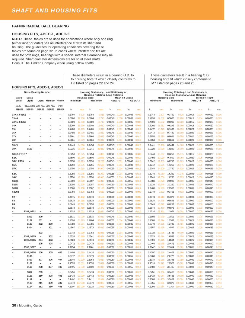
30 / Mounting Guide
SHAFT AND HOUSING FITS
FAFNIR RADIAL BALL BEARING
HOUSING FITS, ABEC-1, ABEC-3NOTE: These tables are to used for applications where only one ring(either inner or outer) has an interference fit with its shaft andhousing. The guidelines for operating conditions covering thesetables are found on page 32. In cases where interference fits areused for both rings, bearings with a special internal clearance may berequired. Shaft diameter dimensions are for solid steel shafts.Consult The Timken Company when using hollow shafts.
These diameters result in a bearing O.D. to These diameters result in a bearing O.D.to housing bore fit which closely conforms to housing bore fit which closely conforms toH6 listed on pages 22 and 24. M7 listed on pages 23 and 25.
HOUSING FITS, ABEC-1, ABEC-3Basic Bearing Number Housing Stationary, Load Stationary or Housing Rotating, Load Stationary or
Housing Rotating, Load Rotating Housing Stationary, Load RotatingExtra Extra Housing Bore Mean Fit Loose Housing Bore Mean Fit TightSmall Light Light Medium Heavy minimum maximum ABEC–1 ABEC–3 minimum maximum ABEC–1 ABEC–3
30, S, F 9100, 9300 200, 7200 300, 7300 7400SERIES SERIES SERIES SERIES SERIES in. mm in mm in. mm in. mm in. mm in mm in. mm in. mm
33K3, F33K3 – – – – 0.3750 9.525 0.3754 9.535 0.00040 0.010 0.00035 0.009 0.3743 9.507 0.3750 9.525 0.00015 0.004 0.00020 0.00533K4 – – – – 0.5000 12.700 0.5004 12.710 0.00040 0.010 0.00035 0.009 0.4993 12.682 0.5000 12.700 0.00015 0.004 0.00020 0.00533K5, F33K5 – – – – 0.5000 12.700 0.5004 12.710 0.00040 0.010 0.00035 0.009 0.4993 12.682 0.5000 12.700 0.00015 0.004 0.00020 0.00534K – – – – 0.6299 15.999 0.6303 16.010 0.00040 0.010 0.00035 0.009 0.6292 15.982 0.6299 15.999 0.00015 0.004 0.00020 0.00535K – – – – 0.7480 18.999 0.7485 19.012 0.00045 0.011 0.00040 0.010 0.7472 18.979 0.7480 18.999 0.00020 0.005 0.00025 0.00636K – – – – 0.7480 18.999 0.7485 19.012 0.00045 0.011 0.00040 0.010 0.7472 18.979 0.7480 18.999 0.00020 0.005 0.00025 0.00637K – – – – 0.8661 21.999 0.8666 22.012 0.00045 0.011 0.00040 0.010 0.8653 21.979 0.8661 29.999 0.00020 0.005 0.00025 0.00638K – – – – 0.8661 21.999 0.8666 22.012 0.00045 0.011 0.00040 0.010 0.8653 21.979 0.8661 21.999 0.00020 0.005 0.00025 0.006
38KV – – – – 0.9449 24.000 0.9454 24.013 0.00045 0.011 0.00040 0.010 0.9441 23.980 0.9449 24.000 0.00020 0.005 0.00025 0.00639K 9100 – – – 1.0236 25.999 1.0241 26.012 0.00045 0.011 0.00040 0.010 1.0228 25.979 1.0236 25.999 0.00020 0.005 0.00025 0.006
S1K7, FS1K7 – – – – 0.6250 15.875 0.6254 15.885 0.00040 0.010 0.00035 0.009 0.6243 15.857 0.6250 15.875 0.00015 0.004 0.00020 0.005S1K – – – – 0.7500 19.050 0.7505 19.063 0.00045 0.011 0.00040 0.010 0.7492 19.030 0.7500 19.050 0.00020 0.005 0.00025 0.006S3K, FS3K – – – – 0.8750 22.225 0.8755 22.238 0.00045 0.011 0.00040 0.010 0.8742 22.205 0.8750 22.225 0.00020 0.005 0.00025 0.006S5K – – – – 1.1250 28.575 1.1255 28.588 0.00045 0.011 0.00040 0.010 1.1242 28.555 1.1250 28.575 0.00020 0.005 0.00025 0.006S7K – – – – 1.3750 34.925 1.3756 34.940 0.00055 0.014 0.00045 0.011 1.3740 34.900 1.3750 34.925 0.00025 0.006 0.00035 0.009
S8K – – – – 1.6250 41.275 1.6256 41.290 0.00055 0.014 0.00045 0.011 1.6240 41.250 1.6250 41.275 0.00025 0.006 0.00035 0.009S9K – – – – 1.8750 47.625 1.8756 47.640 0.00055 0.014 0.00045 0.011 1.8740 47.600 1.8750 47.625 0.00025 0.006 0.00035 0.009S10K – – – – 2.0000 50.800 2.0007 50.818 0.00060 0.015 0.00055 0.014 1.9988 50.770 2.0000 50.800 0.00035 0.009 0.00040 0.010S11K – – – – 2.1250 53.975 2.1257 53.993 0.00060 0.015 0.00055 0.014 2.1238 53.945 2.1250 53.975 0.00035 0.009 0.00040 0.010S12K – – – – 2.2500 57.150 2.2507 57.168 0.00060 0.015 0.00055 0.014 2.2488 57.120 2.2500 57.150 0.00035 0.009 0.00040 0.010F2002 – – – – 0.3750 9.525 0.3753 9.533 0.00000 0.000 0.00000 0.000 0.3749 9.522 0.3753 9.533 0.00000 0.000 0.00000 0.000
F2 – – – – 0.4375 11.112 0.4378 11.120 0.00000 0.000 0.00000 0.000 0.4374 11.110 0.4378 11.120 0.00000 0.000 0.00000 0.000F3 – – – – 0.5624 14.285 0.5628 14.295 0.00000 0.000 0.00000 0.000 0.5624 14.285 0.5628 14.295 0.00000 0.000 0.00000 0.000F4 – – – – 0.6249 15.872 0.6253 15.883 0.00000 0.000 0.00000 0.000 0.6249 15.872 0.6253 15.883 0.00000 0.000 0.00000 0.000F5 – – – – 0.6874 17.460 0.6878 17.470 0.00000 0.000 0.00000 0.000 0.6874 17.460 0.6878 17.476 0.00000 0.000 0.00000 0.000– 9101, 9302 – – – 1.1024 28.001 1.1029 28.014 0.00045 0.011 0.00040 0.010 1.1016 27.981 1.1024 28.001 0.00020 0.005 0.00025 0.006
– 9303 200 – – 1.1811 30.000 1.1816 30.013 0.00045 0.011 0.00040 0.010 1.1803 29.980 1.1811 39.000 0.00020 0.005 0.00025 0.006– 9102 201 – – 1.2598 31.999 1.2604 32.014 0.00055 0.014 0.00045 0.011 1.2588 31.974 1.2598 31.999 0.00025 0.006 0.00035 0.009– 9103 202 300 – 1.3780 35.001 1.3786 35.016 0.00055 0.014 0.00045 0.011 1.3770 34.976 1.3780 35.001 0.00025 0.006 0.00035 0.009– 9304 – 301 – 1.4567 37.000 1.4573 37.015 0.00055 0.014 0.00045 0.011 1.4557 36.975 1.4567 37.000 0.00025 0.006 0.00035 0.009
– – 203 – – 1.5748 40.000 1.5754 40.015 0.00055 0.014 0.00045 0.011 1.5738 39.975 1.5748 40.000 0.00025 0.006 0.00035 0.009– 9104, 9305 – 302 – 1.6535 41.999 1.6541 42.014 0.00055 0.014 0.00045 0.011 1.6525 41.974 1.6535 41.999 0.00025 0.006 0.00035 0.009– 9105, 9306 204 303 – 1.8504 47.000 1.8510 47.015 0.00055 0.014 0.00045 0.011 1.8494 46.975 1.8504 47.000 0.00025 0.006 0.00035 0.009– – 205 304 – 2.0472 51.999 2.0479 52.017 0.00060 0.015 0.00055 0.014 2.0460 51.968 2.0472 51.999 0.00035 0.009 0.00040 0.010– 9106, 9307 – – – 2.1654 55.001 2.1661 55.019 0.00060 0.015 0.00055 0.014 2.1642 54.971 2.1654 55.001 0.00035 0.009 0.00040 0.010
– 9107, 9308 206 305 403 2.4409 61.999 2.4416 62.017 0.00060 0.015 0.00055 0.014 2.4397 61.968 2.4409 61.999 0.00030 0.009 0.00040 0.010– 9108 – – – 2.6772 68.001 2.6779 68.019 0.00060 0.015 0.00055 0.014 2.6760 67.970 2.6772 68.001 0.00030 0.009 0.00040 0.010– 9310 207 306 404 2.8346 71.999 2.8353 72.017 0.00060 0.015 0.00055 0.014 2.8334 71.968 2.8346 71.999 0.00030 0.009 0.00040 0.010– 9109 – – – 2.9528 75.001 2.9535 75.019 0.00060 0.015 0.00055 0.014 2.9516 74.971 2.9528 75.001 0.00030 0.009 0.00040 0.010– 9110 208 307 405 3.1496 80.000 3.1503 80.018 0.00060 0.015 0.00055 0.014 3.1484 79.969 3.1496 80.000 0.00030 0.009 0.00040 0.010
– 9312 209 – – 3.3456 85.001 3.3474 85.024 0.00080 0.019 0.00065 0.017 3.3451 84.966 3.3465 85.001 0.00040 0.010 0.00050 0.013– 9111 210 308 406 3.5433 90.000 3.5442 90.023 0.00080 0.019 0.00065 0.017 3.5419 89.964 3.5433 90.000 0.00040 0.010 0.00050 0.013– 9112 – – – 3.7402 95.001 3.7411 120.424 0.00080 0.019 0.00065 0.017 3.7388 94.965 3.7402 95.001 0.00040 0.010 0.00050 0.013– 9113 211 309 407 3.9370 100.000 3.9379 100.023 0.00080 0.019 0.00065 0.017 3.9356 99.964 3.9370 100.000 0.00040 0.010 0.00050 0.013– 9114 212 310 408 4.3307 110.000 4.3316 110.023 0.00080 0.019 0.00065 0.017 4.3293 109.964 4.3307 110.000 0.00040 0.010 0.00050 0.013
timken_5734mg.pm65 10/2/03, 7:27 AM30

Mounting Guide / 31
SHAFT AND HOUSING FITS
FAFNIR RADIAL BALL BEARING
HOUSING FITS, ABEC-1, ABEC-3NOTE: These tables are to used for applications where only one ring(either inner or outer) has an interference fit with its shaft and housing.The guidelines for operating conditions covering these tables arefound on page 32. In cases where interference fits are used for bothrings, bearings with a special internal clearance may be required.Shaft diameter dimensions are for solid steel shafts. Consult TheTimken Company when using hollow shafts.
These diameters result in a bearing O.D. to These diameters result in a bearing O.D. tohousing bore fit which closely conforms to housing bore fit which closely conforms toH6 listed on pages 22 and 24. M7 listed on pages 23 and 25.
HOUSING FITS, ABEC-1, ABEC-3
Basic Bearing Number Housing Stationary, LoadStationary or Housing Rotating, Load Stationary orHousing Rotating, Load Rotating Housing Stationary, Load Rotating
Extra ExtraSmall Light Light Medium Heavy Housing Bore mean fit loose Housing Bore mean fit tight
30,S,F 9100,9300 200,7200 300,7300 7400 minimum maximum ABEC–1 ABEC–3 minimum maximum ABEC–1 ABEC–3SERIES SERIES SERIES SERIES SERIES in. mm in mm in. mm in. mm in. mm in mm in. mm in. mm
– 9115 – – – 4.5276 115.001 4.5285 115.024 0.0008 0.019 0.00065 0.017 4.5262 114.965 4.5276 115.001 0.0004 0.010 0.00050 0.013– – 213 311 409 4.7244 120.000 4.7253 120.023 0.0008 0.019 0.00065 0.017 4.7230 119.964 4.7244 120.000 0.0004 0.010 0.00050 0.013– – 214 – – 4.9213 125.001 4.9223 125.026 0.0009 0.023 0.00075 0.019 4.9197 124.960 4.9213 125.001 0.0004 0.010 0.00055 0.014– 9117 215 312 410 5.1181 130.000 5.1191 130.025 0.0009 0.023 0.00075 0.019 5.1165 129.959 5.1181 130.000 0.0004 0.010 0.00055 0.014– 9118 216 313 411 5.5118 140.000 5.5128 140.025 0.0009 0.023 0.00075 0.019 5.5102 139.959 5.5118 140.000 0.0004 0.010 0.00055 0.014
– 9120 217 314 412 5.9055 150.000 5.9065 150.025 0.0009 0.023 0.00075 0.019 5.9039 149.959 5.9055 150.000 0.0004 0.010 0.00055 0.014– 120–2 218 315 – 6.2992 160.000 6.3002 160.025 0.0010 0.025 0.00080 0.020 6.2976 159.959 6.2992 160.000 0.0003 0.008 0.00050 0.013– 9121 – – 413 6.2992 160.000 6.3002 160.025 0.0010 0.025 0.00080 0.020 6.2976 159.959 6.2992 160.000 0.0003 0.008 0.00050 0.013– 9122 129 316 – 6.6929 170.000 6.6939 170.025 0.0010 0.025 0.00080 0.020 6.6913 169.959 6.6929 170.000 0.0003 0.008 0.00050 0.013– 122 – – – 6.8898 175.000 6.8908 175.026 0.0010 0.025 0.00080 0.020 6.8882 174.960 6.8898 175.001 0.0003 0.008 0.00050 0.013
– 9124 220 317 414 7.0866 180.000 7.0876 180.025 0.0010 0.025 0.00080 0.020 7.0850 179.959 7.0866 180.000 0.0003 0.008 0.00050 0.013– 124 221 318 415 7.4803 190.000 7.4815 190.028 0.0012 0.029 0.00090 0.023 7.4785 189.954 7.4803 190.000 0.0003 0.008 0.00055 0.014– 9126 222 319 416 7.8740 200.000 7.8752 200.028 0.0012 0.029 0.00090 0.023 7.8722 199.954 7.8740 200.000 0.0003 0.008 0.00055 0.014– 126 – – – 8.0709 205.001 8.0721 205.029 0.0012 0.029 0.00090 0.023 8.0691 204.955 8.0709 205.001 0.0003 0.008 0.00055 0.014– 9128 – – – 8.2677 210.000 8.2689 210.028 0.0012 0.029 0.00090 0.023 8.2659 209.954 8.2677 210.000 0.0003 0.008 0.00055 0.014
– – 224 320 – 8.4646 215.001 8.4658 215.029 0.0012 0.029 0.00090 0.023 8.4628 214.955 8.4646 215.001 0.0003 0.008 0.00055 0.014– 128 – – – 8.6614 220.000 8.6626 220.028 0.0012 0.029 0.00090 0.023 8.6596 219.954 8.6614 220.000 0.0003 0.008 0.00055 0.014– 9130 – 321 418 8.8583 225.001 8.8595 225.029 0.0012 0.029 0.00090 0.023 8.8565 224.955 8.8583 225.001 0.0003 0.008 0.00055 0.014– – 226 – – 9.0551 230.000 9.0563 230.027 0.0012 0.029 0.00090 0.023 9.0533 229.954 9.0551 230.000 0.0003 0.008 0.00055 0.014– 130 – – – 9.2520 235.001 9.2532 235.029 0.0012 0.029 0.00090 0.023 9.2502 234.955 9.2520 235.001 0.0003 0.008 0.00055 0.014
– 9132 – 322 – 9.4488 240.000 9.4506 240.027 0.0012 0.029 0.00090 0.023 9.4470 239.954 9.4488 240.000 0.0003 0.008 0.00055 0.014– 132 228 – – 9.8425 250.000 9.8437 250.027 0.0012 0.029 0.00090 0.023 9.8407 249.954 9.8425 250.000 0.0003 0.008 0.00055 0.014– 9134 – 324 – 10.2362 259.999 10.2374 260.032 0.0013 0.033 0.00105 0.027 10.2342 259.942 10.2362 259.999 0.0003 0.008 0.00060 0.015– 134 – – 420 10.4331 265.001 10.4343 265.034 0.0013 0.033 0.00105 0.027 10.4311 264.950 10.4331 265.001 0.0003 0.008 0.00060 0.015– – 230 – – 10.6299 269.999 10.6311 270.032 0.0013 0.033 0.00105 0.027 10.6279 269.949 10.6299 269.999 0.0003 0.008 0.00060 0.015
– 136,9136 – 326 – 11.0236 279.999 11.0248 280.032 0.0013 0.033 0.00105 0.027 11.0216 279.949 11.0236 279.999 0.0003 0.008 0.00060 0.015– 9138 232 – – 11.4173 289.999 11.4185 290.039 0.0013 0.033 0.00105 0.027 11.4153 289.949 11.4173 289.999 0.0003 0.008 0.00060 0.015– 138 – 328 – 11.8110 299.999 11.8122 300.032 0.0013 0.033 0.00105 0.027 11.8090 299.949 11.8110 299.999 0.0003 0.008 0.00060 0.015– 9140 234 – – 12.2047 309.999 12.2059 310.029 0.0013 0.033 – – 12.2027 309.949 12.2047 309.999 0.0003 0.008 – –
– – 236 330 – 12.5984 319.999 12.5998 320.035 0.0015 0.038 – – 12.5962 319.943 12.5984 319.999 0.0003 0.008 – –– 9144 238 – – 13.3858 339.999 13.3872 340.035 0.0015 0.038 – – 13.3836 339.943 13.3858 339.999 0.0003 0.008 – –– 9146 240 – – 14.1732 359.999 14.1746 360.035 0.0015 0.038 – – 14.1710 359.943 14.1732 359.999 0.0003 0.008 – –– – 242 336 – 14.9606 380.007 14.9620 380.035 0.0015 0.038 – – 14.9584 379.943 14.9606 379.999 0.0003 0.008 – –
– 9152 244 338 – 15.7480 399.999 15.7494 400.035 0.0015 0.038 – – 15.7458 399.943 15.7480 399.999 0.0003 0.008 – –– 9156 246 340 – 16.5354 419.999 16.5370 420.040 0.0017 0.038 – – 16.5329 419.936 16.5354 419.999 0.0004 0.010 – –– – 248 342 – 17.3228 439.999 17.3244 440.040 0.0017 0.038 – – 17.3203 439.936 17.3228 439.999 0.0004 0.010 – –– 9160 250 344 – 18.1102 459.999 18.1118 460.040 0.0017 0.038 – – 18.1077 459.936 18.1102 459.999 0.0004 0.010 – –
– 9164 252 – – 18.8976 479.999 18.8992 480.040 0.0017 0.038 – – 18.8951 479.936 18.8976 479.999 0.0004 0.010 – –– – 256 348 – 19.6850 499.999 19.6866 500.040 0.0017 0.038 – – 19.6825 499.936 19.6850 499.999 0.0004 0.010 – –– – 260 352 – 21.2598 539.999 21.2615 540.042 0.0019 0.048 – – 21.2571 539.930 21.2598 539.999 0.0004 0.010 – –– – 264 356 – 22.8346 579.999 22.8363 580.042 0.0019 0.048 – – 22.8319 579.930 22.8346 579.999 0.0004 0.010 – –
– 9180 – – – 23.6220 599.999 23.6237 600.042 0.0019 0.048 – – 23.6193 599.930 23.6220 599.999 0.0004 0.010 – –
timken_5734mg.pm65 10/2/03, 7:27 AM31

32 / Mounting Guide
SHAFT AND HOUSING FITS
RADIAL BALL AND CYLINDRICALROLLER BEARINGSThese charts are guidelines for specifying shaft and housing fitsrelated to particular operating conditions.
(1) For solid shaft. See pages 18, 19, 20, and 21 for numerical values. (5) Use m5 for accurate applications.(2) Use j5 for accurate applications. (6) C = Dynamic Load Rating.(3) Bearings with greater than nominal clearance must be used. (7) Ce = Extended Dynamic Load Rating (Ball Bearings).(4) Use k5 for accurate applications.
HOUSINGOperating Conditions Examples Housing Outer Ring
Tolerence DisplaceableSymbol (1) Axially
OUTER RING ROTATING
Crane support wheelsHeavy loads with thin-wall housing Wheel hubs (roller bearings) P6 No
Crank bearings
Normal to heavy loads Wheel hubs (ball bearings) N6 NoCrank bearings
Conveyor rollersLight loads Rope sheaves M6 No
Tension pulleys
INDETERMINATE LOAD DIRECTION
Heavy shock loads Electric traction motors M7 No
Electric motorsNormal to heavy loads, axial displacement Pumps K6 no, normallyof outer ring not required. Crankshaft main bearings
Electric motorsLight to normal loads, axial displacement Pumps J6 Yes, normallyof outer ring desired. Crankshaft main bearings
OUTER RING STATIONARY
Shock loads, temporary complete unloading Heavy rail vehicles J6 Yes, normally
AllOne-piece housing
General applications H6 Easilyloads Heavy rail vehicles
Radially split housing Transmission drives H7 Easily
Heat supplied through shaft Dryer cylinders G7 Easily
* Below this line,housing can either
be one – pieceor split; above this
line, a split housing isnot recommended.
(1) Cast iron steel housing. See pages 22,23, 24 and 25 for numerical values.Where wider tolerances are permissible, P7, N7, M7, K7, J7 and H7 values may be used in place of P6, N6, M6, K6, J6, and H6 values respectively.
SHAFTBall Bearings Operating Examples Cylindrical Roller Bearings
(For all nominal diameters) Conditions (Except 5200 Series)
Loads Shaft Loads Shaft Shaft Shaft
Lower Upper Tolerance Lower Upper Diameter Tolerance DiameterLoad Load Symbol Load Load mm Symbol inchLimit Limit Limit Limit
INNER RING STATIONARY
Inner ring to be0 Ce
(7) g6 easily displaced Wheels 0 C(6) All g6 Allon shaft Non-rotating shafts
Inner ring0 Ce h6 does not need Tension pulleys 0 C All h6 All
to be easilydisplaced
INNER RING ROTATING, OR INDETERMINATE
Electrical apparatus 100 140 k6(4) 3.94 5.51Machine tools 140 320 m6(5) 5.51 12.60
0 0.07Ce j6 Light loads Pumps 0 0.08C 320 500 n6 12.60 19.68Ventilators 500 – p6 19.68 –Industrial trucks
Electrical motors 100 140 m6 3.94 5.51Turbines a 140 320 n6 5.51 12.60
0.07Ce 0.15Ce k5 Normal loads Pumps 0.08C 0.18C 320 500 p6 12.60 19.68Combustion engines 500 – r6 19.68 –Gear transmissionsetc. 100 140 n6(3) 3.94 5.51
140 320 p6(3) 5.51 12.600.15Ce Ce m5 Heavy loads Rail vehicles 0.18C C 320 500 r6(3) 12.60 19.68
Shock loads Traction motors 500 – r7(3) 19.68 –
THRUST LOADS
0 Ce j6(3) Pure thrust loads All Not recommended, consult Timken sales office.
timken_5734mg.pm65 10/2/03, 7:27 AM32

Mounting Guide / 33
SHAFT AND HOUSING FITS
RADIAL SPHERICAL ROLLER BEARINGSThese charts are guidelines for specifying shaft and housing fitsrelated to particular operating conditions.
SHAFTConditions Examples Shaft Diameter Tolerance Remarks
mm Symbol
BEARINGS WITH STRAIGHT BORE
The inner ring to be easily Two-bearingStationary displaced on the shaft shaft mechanism s4 See table below for shaft size.
inner
The inner ring not toWheel on non-rotating shaft
All diametersg6
ring loadbe easily displaced on the shaft Tension pulleys and rope sheaves h6
Electrical apparatus, machine Over Incl. In very accurate applicationsLight and variable loads tools, pumps, ventilators, 18 100 k6 k5 and m5 are used insteadP ≤ 0.07C industrial trucks 100 200 m6 of k6 and m6 respectively.
Rotating inner 18 65 m5
ring load or Normal and heavy loads Applications in general, electrical 65 100 m6
indeterminate P > 0.07C motors, turbines, pumps, combustion 100 140 n6
load direction ≤ 0.25C engines, gear transmissions, 140 280 p6
woodworking machines 280 500 r6
500 and up r7
18 65 m6
Very heavy loads and shock loads Journal boxes for locomotives and 65 100 n6 Bearings with greater clearanceP > 0.25C other heavy rail vehicles, 100 140 p6 than normal must be used.
traction motors 140 200 r6
200 500 r7
BEARINGS WITH TAPERED BORE AND ADAPTER SLEEVE
All loads Applications in general All diameters See tables for Reduction of RIC on page 10
(1)For solid steel shaft. See tables on pages 18, 19, 20, and 21 for numerical value.
s4 FITSA centrifugal force load produces a rotating outer ring load and astationary inner ring load, even though the inner ring rotates. Thismakes it desirable to fit the outer ring tight in the housing (using a P6fit as shown on page 24), and the inner ring loose on the shaft usingan s4 fit as listed in the table. The standard W33 bearing with oilgroove and oil holes can be used.
Data shown in ten-thousandths of an inch (6=.0006") or thousandthsof a millimeter (15=0.015 mm.). See dimensional tables for nominalbore.
s4 FITSBore Variance fromNominal Bore
mm Tolerence Shaft Diameter FitOver Incl. +0 max. min.
in. in. in. in.mm mm mm mm
-6 -10 -14 4L
50 8014L
-15 -25 -36 10L36L
-8 -13 -17 5L
80 12017L
-20 -33 -43 13L43L
-10 -16 -21 6L
120 18021L
-25 -41 -53 15L53L
-12 -19 -25 7L
180 25025L
-30 -48 -64 18L64L
timken_5734mg.pm65 10/2/03, 7:27 AM33

34 / Mounting Guide
SHAFT AND HOUSING FITS
HOUSINGConditions Examples Tolerance Remarks
Symbol (2)
Variable load directionTwo-bearingshaft mechanism
P6
Rotating Heavy loads on bearings in Supporting wheels in cranes,
outer thin walled housings wheel hubs, crank bearingsP7
One piecering load Normal and heavy loads Wheel hubs, crank bearings N7 The outer ring is not displaceable axially
bearingLight and variable loads
Conveyor rollers, rope sheaves,housing tension pulleys M7
Heavy shock loads Electrical traction motors
Heavy and normal loads, axialIndeterminate displacement of outer ring Electrical motors, pumps, K7
The outer ring is, as a rule,
load direction not required crankshaft main bearingsnot displaceable axially.
Normal and light loads, axialdisplacement of the outer Electrical motors, pumps,ring desirable crankshaft main bearings The outer ring is, as a rule,
Shock loads, temporarily completeSplit or one unloading Journal boxes for rail vehicles
J7displaceable axially.
piece bearingStationary
All loadsBearing applications in general,
H7housingouter journal boxes for rail vehicles
ring loadNormal and light loads, loads undersimple operating conditions Line shaftings
H8The outer ring is easily displaced axially.
Heat supplied through the shaft Dryer cylinders G7
For main O.D. less than 125mm M6
Very accurate running and small spindles O.D. 125 to 250 mm N6The outer ring is not displaceable axially
deflections under variable loads in machine O.D. over 250mm P6
Applicationstools
One piece requiring Very accurate running underbearing particular light loads and indeterminate
Held bearings in high speedK6
The outer ring is, as a rule,
housing accuracy load directioncentrifugal force compressors not displaceable axially.
Very accurate running, axialFloating bearings in high speed J6 The outer ring is easily displaced axially.displacement of outer ringcentrifugal force compressors
desirable(2) Cast iron or steel housing. For numerical values see tables on pages 22, 23,24, and 25. For housings of lightmetal, tolerances generally are selected which give a slightly tighter fit than those given in the table.
RADIAL SPHERICAL ROLLER BEARINGSThis chart is a guideline for specifying housing fits for particularoperating conditions.
timken_5734mg.pm65 10/2/03, 7:27 AM34
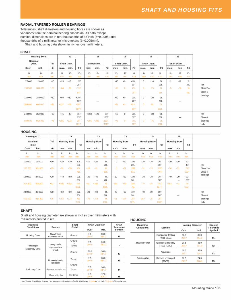
Mounting Guide / 35
SHAFT AND HOUSING FITS
RADIAL TAPERED ROLLER BEARINGSTolerences, shaft diameters and housing bores are shown asvariances from the nominal bearing dimension. All data exceptnominal dimensions are in ten-thousandths of an inch (5=0.0005) andthousandths of a millimeter or micrometers (5=0.005mm).
Shaft and housing data shown in inches over millimeters.
SHAFTBearing Bore t1 t2 t3 t4 t5
Nominal(min.) Tol. Shaft Diam. Shaft Diam. Shaft Diam. Shaft Diam. Shaft Diam.
Over Incl. –0 max. min. Fit max. min. Fit max. min. Fit max. min. Fit max. min. Fit
in in. in. in. in. in. in. in. in. in. in. in. in. in. in. in. in. in.mm mm mm mm mm mm mm mm mm mm mm mm mm mm mm mm mm mm
7.5000 12.0000 +10 +25 +15 5T +10 +0 +10L 0 -10 0L -2 -12 2L25T — 10T 20L 22L For
190.500 304.800 +25 +64 +38 +13T +25 0 25L 0 -25 0L -5 -30 5L Class 2 or
64T 25T 51L 56L Class 4
12.0000 24.0000 +20 +50 +30 +10T +20 +0 20L 0 -20 0Lbearings
50T — 20T 40L —304.800 609.600 +51 +127 +76 +25T +51 +0 +51L 0 -51 0L
127T 51T 102L
24.0000 36.0000 +30 +75 +45 15T +150 +120 90T +30 0 30L 0 -30 0L For75T 150T 30T 60L — Class 4
609.600 914.400 +76 +191 +114 38T +381 +305 229T +76 0 76L 0 -76 0L bearings191T 381T 76T 152L only
Bearing O.D. T1 T2 T3 T4 T5
Nominal Tol. Housing Bore Housing Bore Housing Bore Housing Bore Housing Bore
(min.) Fit Fit Fit Fit Fit
Over Incl. –0 max. min. max. min. max. min. max. min. max. min.
in in. in. in. in. in. in. in. in. in. in. in. in. in. in. in. in. in.mm mm mm mm mm mm mm mm mm mm mm mm mm mm mm mm mm mm
10.5000 12.0000 +10 +20 +30 10L +10 +20 0L 0 +20 10T -20 -10 10T -30 -20 20T30L – 20L 20L 30T 40T For
266.700 304.800 +25 +51 +76 25L +25 +51 0L 0 +51 25T -51 -25 25T -76 -51 51T Class 2 or76L 51L 51L 76T 102T Class 4
12.0000 24.0000 +20 +40 +60 20L +20 +40 0L +10 +30 10T -30 -10 10T -40 -20 20Tbearings
60L – 40L 30L 50T – 60T304.800 609.600 +51 +102 +152 51L +51 +102 0L +25 +76 25T -76 -25 25T -102 -51 51T
152L 102L 76L 127T 152T
24.0000 36.0000 +30 +60 +90 30L +30 +60 0L +20 +50 10T -40 -10 10T For90L 60L 50L 70T — Class 4
609.600 914.400 +76 +152 +114 76L +76 +152 0L +51 +127 25T -102 -25 25T bearings229L 152L 127L 178T only
HOUSING
SHAFTShaft and housing diameter are shown in inches over millimeters withmillimeters printed in red.
Mounting Shaft Shaft Diameter ShaftConditions Service Finish Tolerance
Over Incl. Symbol
Steady load 7.5 36.0Rotating Cone moderate shock Ground 190.5 914.0 t1
Ground
Heavy loads, or 7.5 24.0
Rotating orhigh speeds or
Turned 190.5 610.0 *Stationary Cone shock
Ground 24.0 36.0610.0 914.0 t2
Moderate loads, Turned 7.5 36.0
no shock190.5 914.0 t3
Ground7.5 36.0
Stationary Cone Sheaves, wheels, etc. Turned 190.5 914.0 t4
7.5 12.0Wheel spindles Hardened190.5 305.0 t5
HOUSINGMounting Housing Diameter Housing
Conditions Service ToleranceOver Incl. Symbol
Clamped or floating 10.5 36.0(TDO) styles 266.7 914.0 T1
Stationary Cup Alternate clamp only 10.5 36.0(TDO, TDOC) 266.7 914.0 T2
10.5 36.0Adjustable
266.7 914.0 T3
Rotating Cup Sheaves unclamped 10.5 24.0(TDOC) 266.7 160.0 T5
*Use “Turned Shaft Fitting Practice, “ an average cone interference fit of 0.0005 inches (0.013mm) per inch (25.4mm) of bore diameter.
timken_5734mg.pm65 10/2/03, 7:27 AM35

36 / Mounting Guide
TYPE TVB TYPE TVL AND DTVLSHAFT SHAFT
Bearing Bore Shaft Diameter Bearing Bore Shaft Diameternominal (min.) nominal (max.) Interference Fit* Loose Fit**
Over Incl. Max. Min. Over Incl. Max. Min. Max. Min.
in. in. in. in. in. in. in. in. in. in.mm mm mm mm mm mm mm mm mm mm
0.0000 6.7500 +0 -0.0012 0.0000 19.8750 +0.0030 +0 -0.0060 -0.00300.000 171.450 +0 -0.030 0.000 504.825 +0.076 +0 -0.152 -0.076
6.7500 20.0000 +0 -0.0015 19.8750 60.0000 +0.0050 +0 -0.0100 -0.0050171.450 508.000 +0 -0.038 504.825 1524.000 +0.127 +0 -0.254 -0.127
HOUSING HOUSINGBearing O.D. Housing Bore Bearing O.D. Shaft Diameter
nominal (max.) nominal (min.) Loose Fit** Interference Fit*Over Incl. Max. Min. Over Incl. Max. Min. Max. Min.
in. in. in. in. in. in. in. in. in. in.mm mm mm mm mm mm mm mm mm mm
4.7188 17.3750 +0.0090 +0.0050 0.0000 23.0000 +0.0060 0.0030 -0.0060 -0.0030119.858 441.325 +0.229 +0.127 0.000 584.000 +0.152 0.076 -0.152 -0.076
17.3750 39.3701 +0.0100 +0.0060 23.0000 70.0000 +0.0100 0.0050 -0.0100 -0.0050441.325 1000.000 +0.254 +0.152 584.000 1778.000 +0.254 0.127 -0.254 -0.127
TORRINGTON THRUST CYLINDRICAL ROLLER BEARINGSTYPE TP AND TPS TYPE TPSHAFT HOUSING
Bearing Bore Shaft Diameter Bearing O.D. Housing Bore
nominal (max.) nominal (min.)
Over Incl. Max. Min. Over Incl. Max. Min.
in. in. in. in. in. in. in. in.mm mm mm mm mm mm mm mm
1.8750 2.1250 -0.0010 -0.0020 4.5312 10.0000 +0.0030 +0.001547.625 53.975 -0.025 -0.051 115.092 254.000 +0.076 +0.038
2.1250 2.5000 -0.0011 -0.0021 10.0000 18.0000 +0.0040 +0.00253.975 63.500 -0.028 -0.053 254.000 457.200 +0.102 +0.051
2.5000 3.0000 -0.0012 -0.0022 18.0000 22.0000 +0.0050 +0.002563.500 76.200 -0.030 -0.056 457.200 558.800 +0.127 +0.064
3.0000 3.5000 -0.0012 -0.0023 22.0000 26.0000 +0.0055 +0.002576.200 88.900 -0.033 -0.058 558.800 660.400 +0.140 +0.064
3.5000 7.0000 -0.0015 -0.0025 26.0000 28.0000 +0.0060 +0.003088.900 177.800 -0.038 -0.064 660.400 711.200 +0.152 +0.076
7.0000 9.0000 -0.0015 -0.0030 28.0000 34.0000 +0.0070 +0.0030177.800 228.600 -0.038 -0.076 711.200 863.600 +0.178 +0.076
9.0000 12.0000 -0.0018 -0.0330 34.0000 38.0000 +0.0080 +0.0035228.600 304.800 -0.046 -0.084 863.600 965.200 +0.203 +0.089
12.0000 15.0000 -0.0020 -0.0035 38.0000 44.0000 +0.0090 +0.0040304.800 381.000 -0.051 -0.089 965.200 1117.600 +0.229 +0.102
15.0000 19.0000 -0.0020 -0.0040381.000 482.600 -0.051 -0.102
19.0000 23.0000 -0.0025 -0.0045482.600 584.200 -0.064 -0.114
23.0000` 30.0000 -0.0030 -0.0055` 584.200 762.000 -0.076 -0.140
SHAFT AND HOUSING FITS
TORRINGTON THRUST BALL BEARINGSShaft and housing diameters shown as variance from nominaldimensions. Shaft and housing data shown in inches over millimeters.
* Dowel pin suggested. ** Dowel pin required.
* Dowel pin suggested. ** Dowel pin required.
Note: Housing fits for Type TPS are on the following page.
timken_5734mg.pm65 10/2/03, 7:27 AM36

Mounting Guide / 37
TYPE TPSHOUSING Deviations in 0.0001 inches/0.001 micrometers
Bearing O.D. Housing Diameternominal (min.) Deviation from D
Over Incl. High Low
in. in. in. in.mm mm mm mm
2.0000 2.3750 +15 +550.800 60.325 +38 +132.3750 3.2500 +17 +760.325 82.550 +43 +183.2500 3.6875 +19 +982.550 93.663 +48 +233.6875 4.0000 +21 +1193.663 101.600 +53 +284.0000 4.5312 +28 +13
101.600 115.092 +71 +33
4.5312 10.0000 +30 +15115.092 254.000 +76 +3810.0000 18.0000 +40 +20254.000 457.200 +102 +5118.0000 22.0000 +50 +25457.200 558.800 +127 +6422.0000 26.0000 +55 +25558.800 660.400 +140 +6426.0000 28.0000 +60 +30660.400 711.200 +152 +76
28.0000 34.0000 +70 +30711.200 863.600 +178 +7634.0000 38.0000 +80 +35863.600 965.200 +203 +8938.0000 44.0000 +90 +40965.200 1117.600 +229 +102
TORRINGTON THRUST TAPERED ROLLER BEARINGS
TYPE TTHD SHAFT TYPE TTHD HOUSINGShaft Diameter
Bearing Bore Spring Rolling Mill Screwdownnominal (min.) Loaded & Piercing Mill Bearing O.D. Housing Bore
Max.+0 Thrust Blocks nominal (min.)Over Incl. Min. Max. Min. Over Incl. max. min.
in. in. in. in. in. in. in. in. in.mm mm mm mm mm mm mm mm mm
0.0000 6.8750 -0.0010 +0.0030 +0.0020 6.3750 10.5000 +0.0025 +0.00100.000 174.625 -0.025 +0.076 +0.051 161.925 266.700 +0.064 +0.025
6.8750 7.9999 -0.0010 +0.0040 +0.0030 10.5000 13.0000 +0.0030 +0.0010174.625 203.197 -0.025 +0.102 +0.076 266.700 330.200 +0.076 +0.025
7.9999 12.0000 -0.0015 +0.0050 +0.0040 13.0000 20.0000 +0.0040 +0.0020203.197 304.800 -0.038 +0.127 +0.102 330.200 508.000 +0.102 +0.051
12.0000 24.0000 -0.0020 +0.0070 +0.0050 20.0000 25.0000 +0.0045 +0.0020304.800 609.600 -0.051 +0.178 +0.127 508.000 635.000 +0.114 +0.051
24.0000 36.0000 -0.0025 +0.0095 +0.0070 25.0000 30.0000 +0.0060 +0.0030609.600 914.400 -0.064 +0.241 +0.178 635.000 762.000 +0.152 +0.076
36.0000 48.0000 -0.0030 +0.0120 +0.0090 30.0000 35.0000 +0.0070 +0.0030914.400 1219.200 -0.076 +0.304 +0.229 762.000 889.000 +0.178 +0.076
SHAFT AND HOUSING FITS
TORRINGTON THRUST CYLINDRICAL ROLLER BEARINGSTolerances for housing bore and for shaft diameters shown as variancefrom nominal bearing dimension.
Data shown in inches over millimeters
timken_5734mg.pm65 10/2/03, 7:27 AM37

38 / Mounting Guide
SHAFT AND HOUSING FITS
TORRINGTON THRUST TAPERED ROLLER BEARINGSTolerences for housing bore and shaft diameters shown as variancefrom nominal bearing dimension.
Data shown in inches over millimeters.When one washer is piloted by the housing, sufficient clearances
must be allowed at the outside diameter of the other washer as wellas at the bore of both washers to prevent cross-threading of therollers. For most applications, this clearance is approximately 1⁄16"(.0625", .1588mm).
TORRINGTON THRUST SPHERICAL ROLLER BEARINGTolerances for housing bore and for shaft diameters shown asvariance from nominal bearing dimension.
Data shown in inches over millimeters.When application calls for thrust loads only, the housing must be
relieved by 1⁄16" on diameter so that no radial load is carried on thebearing.
HOUSINGTolerances are 1/10,000 of an inch (5 =.0005") and 1/1000 of a millimeter( µm )
Bearing O.D. Housing Borenominal (max.)
Springs in Combined Axial &Radial LoadHousing
Light Radial Stationary Rotatinginches Load Outer Ring Outer Ring
Over Incl. min. max. min. max. min. max.
in. in. in. in. in. in. in. in.
mm mm mm mm mm mm mm mm
7.0866 9.8425 +6 +24 -7 +11 -13 +5180 250 +15 +61 -18 +28 -33 +13
9.8425 12.4016 +7 +27 -7 +13 -14 +6
250 315 +18 +69 -18 +33 -36 +15
12.4016 15.7480 +7 +29 -7 +15 -16 +6
315 400 +18 +74 -18 +38 -41 +15
15.7480 19.6850 +8 +33 -9 +16 -18 +7
400 500 +20 +84 -23 +41 -46 +18
19.6850 24.8031 +9 +36 -9 +18 -19 +8
500 630 +23 +91 -23 +46 -48 +20
24.8031 31.4960 +9 +40 -9 +20 -20 +9
630 800 +23 +102 -23 +51 -51 +23
31.4960 39.3700 +10 +43 -10 +23 -23 +10
800 1000 +25 +109 -25 +58 -58 +25
39.3700 49.2126 +11 +48 -11 +26 -25 +12
1000 1250 +28 +122 -28 +66 -64 +30
SHAFTTolerances are 1/10,000 of an inch (5 =.0005") and 1/1000 of a millimeter( µm )
Bearing Bore Shaft Diameternominal (max.) Stationary Load Rotating Load
inchesOver Incl. max. min. max. min.
in. in. in. in. in. in.mm mm mm mm mm mm
3.1496 4.7244 +5 -4 +10 +1
80 120 +13 -10 +25 +3
4.7244 7.0866 +6 -4 +11 +1
120 180 +15 -10 +28 +3
7.0866 7.8740 +7 -5 +1 +2
180 200 +18 -13 +36 +5
7.8740 9.4488 +7 -5 +18 +6
200 240 +18 -13 +46 +15
9.4488 12.4016 +7 -6 +20 +8
240 315 +18 -15 +51 +20
12.4016 15.7480 +7 -7 +22 +8
315 400 +18 -18 +56 +20
15.7480 19.6850 +9 -7 +34 +18
400 500 +23 -18 +86 +46
19.6850 24.8031 +9 -8 +34 +17
500 630 +23 -20 +86 +43
Housing Bore
Shaft Diameter
TYPES TTV AND TTVFSHAFT HOUSING
Bearing Bore Shaft Diameter Bearing Bore Housing Borenominal (min.) Max. +O nominal (min.)
Over Incl. Min. Over Incl. max. min.
in. in. in. in. in. in. in.mm mm mm mm mm mm mm
0.0000 12.0000 -0.0020 6.3750 10.4375 +0.0025 +0.00100.000 304.800 -0.051 161.925 265.113 +0.060 +0.025
12.0000 20.0000 -0.0020 10.3475 12.5000 +0.0030 +0.0010304.800 508.000 -0.051 265.113 317.500 +0.076 +0.025
20.0000 28.0000 -0.0030 12.5000 19.0000 +0.0040 +0.0020508.000 711.200 -0.076 317.500 482.600 +0.102 +0.051
28.0000 48.0000 -0.0040 19.0000 23.7500 +0.0045 +0.0020711.200 1219.200 -0.102 482.600 603.250 +0.113 +0.051
48.0000 68.0000 -0.0050 23.7500 28.0000 +0.0060 +0.00301219.200 1727.200 -0.127 603.250 711.200 +0.152 +0.076
28.0000 33.0000 +0.0070 +0.0030711.200 838.200 +0.178 +0.076
timken_5734mg.pm65 10/2/03, 7:27 AM38

Mounting Guide / 39
SHAFT AND HOUSING FITS
Shaft and housing shoulder diameters for radial roller and thrust balland thrust ball and roller bearings are also found in the respectivedimension tables. Shaft and Housing shoulders for ball bearings areshown below.
FAFNIR RADIAL BALL BEARINGSThe preferred method of locating bearings on shafts and in housingsis to provide accurate shoulders perpendicular to the shaft axis.Shoulders should be large enough to exceed the theoretical point oftangency between the corner radius and the face of the bearing, andsmall enough to permit bearing removal with proper pullers. These tables give the recommended maximum and minimum shaftand housing shoulder diameters for the majority of applications. Wheredesign limitations do not permit conformance to these recommendeddiameters, the Engineering department should be consulted. Recommended shaft and housing fillet radii are listed in thedimensional tables of each product catalog and must be used toassure proper seating against shaft and housing shoulders. Shaft and housing diameters for radial ball bearings are shownbelow and on the following two pages. For radial cylindrical, sphericaland tapered roller bearings refer to the respective dimension tables.Housing shoulders for wide inner ring bearings are shown on page 44.
EXTRA LIGHT 9300 EXTRA-SMALL SERIES
Basic shaft housing Basic Shoulder DiametersBearing shoulder shoulder Bearing shaft, S housing, HNumber ±.010" ±.010" Number max. min. max. min.
in. mm in. mm in. mm in. mm in. mm in. mm
9301K 0.58 14.7 0.85 21.6 33K3 0.20 5.1 0.19 4.8 0.32 8.1 0.31 7.99302K 0.70 17.8 1.00 25.4 33K4 0.24 6.1 0.23 5.8 0.44 11.2 0.43 10.99303K 0.78 19.8 1.08 27.4 33K5 0.26 6.6 0.25 6.4 0.44 11.2 0.43 10.99304K 0.94 23.9 1.32 33.5 34K 0.26 6.6 0.25 6.4 0.56 14.2 0.55 14.09305K 1.14 29.0 1.52 38.6 35K 0.37 9.4 0.36 9.1 0.67 17.0 0.66 16.89306K 1.32 33.5 1.71 43.4 36K 0.37 9.4 0.36 9.1 0.67 17.0 0.66 16.89307K 1.56 39.6 2.00 50.8 37K 0.44 11.2 0.42 10.7 0.79 20.1 0.77 19.69308K 1.77 45.0 2.26 57.4 38K 0.45 11.4 0.43 10.9 0.79 20.1 0.77 19.69309K 1.98 50.3 2.49 63.2 38KV 0.45 11.4 0.43 10.9 0.79 20.1 0.77 19.69310K 2.16 54.9 2.66 67.6 39K 0.51 13.0 0.49 12.5 0.91 23.1 0.89 22.69311K 2.40 61.0 2.94 74.7 S1K7 0.34 8.6 0.32 8.1 0.56 14.2 0.54 13.79312K 2.59 65.8 3.14 79.8 S1K 0.37 9.4 0.35 8.9 0.69 17.5 0.67 17.0
S3K 0.50 12.7 0.48 12.2 0.80 20.3 0.78 19.8S5K 0.63 16.0 0.61 15.5 0.99 25.1 0.97 24.6S7K 0.84 21.3 0.80 20.3 1.24 31.5 1.20 30.5S8K 0.97 24.6 0.93 23.6 1.46 37.1 1.40 35.6S9K 1.14 28.9 1.10 27.9 1.65 41.9 1.61 40.9S10K 1.24 31.5 1.20 30.5 1.84 46.7 1.80 45.7S11K 1.34 34.0 1.30 33.0 1.95 49.5 1.91 48.5S12K 1.55 39.4 1.51 38.4 2.20 55.9 2.00 50.8
SH
timken_5734mg.pm65 10/2/03, 7:27 AM39

40 / Mounting Guide
SHAFT DESIGN – TORRINGTON NEEDLE BEARINGS
When the shaft is used as the inner raceway for needle rollerbearings the following specifications must be met:
1. metallurgy – either case hardening or through hardening gradesof good bearing quality steel are satisfactory for raceways. Steelswhich are modified for free machining, such as those high in sulfurcontent and particularly those containing lead, are seldomsatisfactory for raceways.
To realize full bearing capacity, the raceway area must be atleast surface hard with a reasonable core strength. The preferredsurface hardness is equivalent to 58 HRC. If the raceway is oflesser hardness, see the modification factors shown in Tables 2and 3.
Shaft raceways for all needle roller bearings, in diameters up to3.5 inches or 90mm should have an effective case depth of 0.030inch or 0.8mm. (Effective case depth is defined as the distancefrom the surface, after final grinding, to the 50 HRC hardnesslevel.) For raceways larger than 3.5 inches or 90 mm in diameterthe effective case depth should be 0.050 inch or 1.3 mm.
2. strength – the shaft must be of sufficient size to keep theoperating deflections within limits.
3. tolerance – the recommended shaft diameter tolerances for eachtype of needle roller bearing are indicated on the tabular pages.
4. taper – the taper within the length of the bearing raceway shouldnot exceed 0.0003 inch (0.008 mm), or one-half the diametertolerance, whichever is smaller.
5. out-of-roundness – the radial deviation from true circular form ofthe raceway should not exceed .0001 inch (0.0025mm) fordiameters up to and including 1.0 inch (25mm). For racewaysgreater than 1.0 inch or 25mm the allowable radial deviation maybe greater than .0001 inch (0.0025mm) by a factor of racewaydiameter (in inches) divided by 1.0 or a factor of raceway diameter(in mm ) divided by 25.
6. surface finish – the raceway finish should not exceed 8 micro-inches aa (arithmetic average) or 0,2 µm (on the Ra scale). Inaddition, the raceway area must be free of nicks, scratches anddents. Oil holes are permissible in the raceway area but care mustbe taken to blend the edges gently into the raceway.
Care must be taken to prevent grind reliefs, fillets, etc., fromextending into the raceway area. If the rollers overhang a grindrelief or step on the shaft, there will be high stress concentrationwith resultant early failure.
7. end chamfer – for most effective assembly of the shaft into abearing, the end of the shaft should have a large chamfer orrounding. This should help in preventing damage to the rollercomplement, scratching of the raceway surface and nicking of theshaft end.
8. sealing surface – in some instances bearings have integral orimmediately adjacent seals that operate on the surface ground forthe bearing raceway. Here, particular attention should be paid tothe pattern of the shaft finish. In no instance should there be a“lead”, or spiral effect, as often occurs with through feed centerlessgrinding. Such a “lead” may pump lubricant past the seal.
When it is undesirable or impractical to prepare the shaft to beused as a raceway, inner rings are available as listed in the tabularpages. If the shaft is not used directly as a raceway, the followingdesign specifications must be met:
1. strength – the shaft must be of sufficient size to keep theoperating deflections within limits.
2. tolerance – the recommended shaft diameter tolerances formounting inner rings are indicated on the tabular pages.
3. taper and out-of-roundness – the taper and out-of-roundnessshould not exceed one-half the shaft diameter tolerance.
4. surface finish – the surface finish should not exceed 125microinches, aa (arithmetic average) or 3.2 µm (on the Ra scale).
5. locating shoulders or steps – locating shoulders or steps in theshaft must be held to close concentricity with the bearing seat toprevent imbalance and resultant vibrations.
SHAFT DESIGN
timken_5734mg.pm65 10/2/03, 7:27 AM40
Mounting Guide / 41
HOUSING DESIGN – TORRINGTON NEEDLE BEARINGS
BEARINGS WITH OUTER RINGSFor bearings with outer rings the function of the housing is to locateand support the outer ring. The following specifications must be met:
1. strength – housings should be designed so that the radialloads which will be placed on the bearings will cause a minimum ofdeflection or distortion of the housing.
2. tolerance – the recommended housing bore tolerances foreach type of needle roller bearing are indicated on the tabular pages.
3. taper – the taper within the length of the outer ring should notexceed .0005 inch (0.013 mm).
4.out-of-roundness – the housing bore should be round withinone-half the housing bore diameter tolerance.
5. parallelism – when possible, line bore housings which arecommon to one shaft to obtain parallelism of the housing bores andthe shaft axis.
6. surface finish – the surface finish of housing bore should notexceed 125 microinches, aa (arithmetic average) or 3.2 µm (on theRa scale).
7. end chamfer – to permit easy introduction of the bearing intothe housing, the end of the housing should have a generous chamfer.
Heavy duty roller bearings can be installed into housings with atransition fit or a clearance fit. The outer ring should be a transition fitin the housing when it rotates relative with the load. The outer ringmay be a clearance fit in the housing when it is stationary relative tothe load.In either case, locate the bearings by shoulders, or otherlocating devises, to prevent axial movement.
Since the heavy duty roller bearing does not require an interfer-ence fit in the housing to round and size it properly, a split housingmay be used if desired. Dowels should be used to maintain properregister of the housing sections.
Drawn cup bearings have a thin case-hardened outer ring which isout-of-round from the hardening operation. For proper mounting itmust always be pressed into the housing. Split housing will not roundand size a drawn cup bearing. When split housings must be used, thebearing should first be mounted in a cylindrical sleeve.
The housing should be of sufficient tensile strength and sectionto round and size the bearing. It must be designed for minimumdistortion under load. Steel or cast iron housings are preferred.Housing bores in low tensile strength materials such as aluminum,magnesium, phenolics, etc., should be reduced to provide moreinterference fit. Thin section cast iron and steel housings may alsorequire reduced bores. Consult The Timken Company for recommen-dations when working with these lower strength housings.
The housing should be through bored if possible. When shoul-dered housing bores are unavoidable, the bearing should be locatedfar enough from the shoulder to avoid the danger of crushing the endof the drawn cup during installation.
When the drawn cup bearing is mounted close to the housingface, care should be taken to mount the bearing at least 0.008 inch(0.20 mm) within the housing face to protect the bearing lip.
BEARINGS WITHOUT OUTER RINGSIn many cases, such as with gear bores, it is desirable to have thehousing bore serve as the outer raceway for caged needle rollerassemblies or loose needle roller complements. In those instances,the following specifications must be met:
1. strength – the housing must be of sufficient cross section tomaintain proper roundness and running clearance under themaximum load.
2. metallurgica l – material selection, hardness and case depthshould be consistent with the requirements for inner racewaysgiven in the SHAFT DESIGN recommendations on page 40.
3. taper and out-of-roundness – the raceway out-of-roundness andtaper should not exceed 0.0003 inch (0.008 mm) or one-half thebore tolerance, whichever is smaller. In addition, the bore diametermust never be smaller at both ends than in the center (sway-back).
4. surface finish – the raceway surface finish should not exceed 8microinches, aa (arithmetic average) or 0.2 µm (on the Ra scale).In addition, the surface must be free of nicks, dents and scratches.
5. grind reliefs – care must be exercised to ensure that grindreliefes, fillets, etc. do not extend to the raceway. Oil holes in theraceway area are permissible but the edges must be blendedsmoothly with the raceway.
HOUSING DESIGN
timken_5734mg.pm65 10/2/03, 7:27 AM41

42 / Mounting Guide
SHAFT AND HOUSING SHOULDERS
Extra-Light • 9100 Series Light • 200, 5200, 7200WN Series Medium • 300, 5300, 7300WN Series
Basic Shoulder Diameters Basic Shoulder Diameters Basic Shoulder DiametersBearing shaft, S housing, H Bearing shaft, S housing, H Bearing shaft, S housing, HNumber max. min. max. min. Number max. min. max. min. Number max. min. max. min.
in. mm in. mm in. mm in. mm in. mm in. mm in. mm in. mm in. mm in. mm in. mm in. mm
9100 0.52 13.2 0.47 11.9 0.95 24.1 0.91 23.1 200 0.56 14.2 0.50 12.7 0.98 24.9 0.97 24.6 300 0.59 15.0 0.50 12.7 1.18 30.0 1.15 29.29101 0.71 18.0 0.55 14.0 1.02 25.9 0.97 24.6 201 0.64 16.3 0.58 14.7 1.06 26.9 1.05 26.7 301 0.69 17.5 0.63 16.0 1.22 31.0 1.21 30.79102 0.75 19.0 0.67 17.0 1.18 30.0 1.13 28.7 202 0.75 19.0 0.69 17.5 1.18 30.0 1.15 29.2 302 0.81 20.6 0.75 19.0 1.42 36.1 1.40 35.69103 0.81 20.6 0.75 19.0 1.30 33.0 1.25 31.8 203 0.84 21.3 0.77 19.6 1.34 34.0 1.31 33.3 303 0.91 23.1 0.83 21.1 1.61 40.9 1.60 40.69104 0.98 24.9 0.89 22.6 1.46 37.1 1.41 35.8 204 1.00 25.4 0.94 23.9 1.61 40.9 1.58 40.1 304 1.06 26.9 0.94 23.9 1.77 45.0 1.75 44.4
9105 1.18 30.0 1.08 27.4 1.65 41.9 1.60 40.6 205 1.22 31.0 1.14 29.0 1.81 46.0 1.78 45.2 305 1.31 33.3 1.14 29.0 2.17 55.1 2.09 53.19106 1.38 35.1 1.34 34.0 1.93 49.0 1.88 47.8 206 1.47 37.3 1.34 34.0 2.21 56.1 2.16 54.9 306 1.56 39.6 1.34 34.0 2.56 65.0 2.44 62.09107 1.63 41.4 1.53 38.9 2.21 56.1 2.15 54.6 207 1.72 43.7 1.53 38.9 2.56 65.0 2.47 62.7 307 1.78 45.2 1.69 42.9 2.80 71.1 2.72 69.19108 1.81 46.0 1.73 43.9 2.44 62.0 2.39 60.7 208 1.94 49.3 1.73 43.9 2.87 72.9 2.78 70.6 308 2.00 50.8 1.93 49.0 3.19 81.0 3.06 77.79109 2.03 51.6 1.94 49.3 2.72 69.1 2.67 67.8 209 2.13 54.1 1.94 49.3 3.07 78.0 2.97 75.4 309 2.28 57.9 2.13 54.1 3.58 90.9 3.41 86.6
9110 2.22 56.4 2.13 54.1 2.91 73.9 2.86 72.6 210 2.34 59.4 2.13 54.1 3.27 83.1 3.17 80.5 310 2.50 63.5 2.36 59.9 3.94 100.1 3.75 95.29111 2.48 63.0 2.33 59.2 3.27 83.1 3.22 81.8 211 2.54 64.5 2.41 61.2 3.68 93.5 3.56 90.4 311 2.75 69.8 2.56 65.0 4.33 110.0 4.13 104.99112 2.67 67.8 2.53 64.3 3.47 88.1 3.42 86.9 212 2.81 71.4 2.67 67.8 3.98 101.1 3.87 98.3 312 2.94 74.7 2.84 72.1 4.65 118.1 4.44 112.89113 2.84 72.1 2.72 69.1 3.66 93.0 3.61 81.7 213 3.03 77.0 2.86 72.6 4.37 111.0 4.19 106.4 313 3.19 81.0 3.03 77.0 5.04 128.0 4.81 122.29114 3.11 79.0 2.91 73.9 4.06 103.1 3.97 100.8 214 3.22 81.8 3.06 77.7 4.57 116.1 4.41 112.0 314 3.44 87.4 3.23 82.0 5.43 137.9 5.13 130.3
9115 3.31 84.1 3.11 79.0 4.25 108.0 4.16 105.7 215 3.44 87.4 3.25 82.6 4.76 120.9 4.59 116.6 315 3.88 98.6 3.43 87.1 5.83 148.1 5.50 139.79116 3.56 90.4 3.31 84.1 4.65 118.1 4.50 114.3 216 3.69 93.7 3.55 90.2 5.12 130.0 4.93 125.2 316 3.94 100.1 3.62 91.9 6.22 158.0 5.88 149.49117 3.75 95.2 3.50 88.9 4.84 122.9 4.71 119.6 217 3.88 98.6 3.75 95.2 5.51 140.0 5.31 134.9 317 4.13 104.9 3.90 99.1 6.54 166.1 6.19 157.29118 4.03 102.4 3.84 97.5 5.16 131.1 5.13 130.3 218 4.16 105.7 3.94 100.1 5.91 150.1 5.62 142.7 318 4.38 111.3 4.09 103.9 6.93 176.0 6.50 165.19120 4.38 111.3 4.23 107.4 5.55 141.0 5.44 138.2 219 4.38 111.3 4.21 106.9 6.22 158.0 6.06 153.9 319 4.63 117.6 4.29 109.0 7.32 185.9 6.88 174.8
9121 4.66 118.4 4.53 115.1 5.91 150.1 5.75 146.0 220 4.63 117.6 4.41 112.0 6.61 167.9 6.31 160.3 320 4.88 124.0 4.49 114.0 7.91 200.9 7.38 187.49122 4.91 124.7 4.72 119.9 6.30 160.0 6.18 157.0 221 4.88 124.0 4.61 117.1 7.01 178.1 6.88 174.8 321 5.13 130.3 4.69 119.1 8.31 211.1 7.75 196.89124 5.28 134.1 5.12 130.0 6.69 169.9 6.50 165.1 222 5.13 130.3 4.80 121.9 7.40 188.0 7.06 179.3 322 5.50 139.7 4.88 124.0 8.90 226.1 8.25 209.69126 5.81 147.6 5.51 140.0 7.48 190.0 7.25 184.1 224 5.63 143.0 5.20 132.1 7.99 202.9 7.56 192.0 324 6.00 152.4 5.28 134.1 9.69 246.1 8.93 226.89128 6.06 153.9 5.81 147.6 7.88 200.2 7.68 195.1 226 6.00 152.4 5.67 144.0 8.50 215.9 8.13 206.5 326 6.44 163.6 5.83 148.1 10.32 262.1 9.69 246.1
9130 6.59 167.4 6.38 162.1 8.39 213.1 8.13 206.5 228 6.50 165.1 6.06 153.9 9.29 236.0 8.81 223.8 328 6.93 176.0 6.22 158.0 11.10 281.9 10.38 263.79132 6.96 176.8 6.56 166.6 9.00 228.6 8.75 222.2 230 6.97 177.0 6.46 164.1 10.08 256.0 9.50 241.3 330 7.44 189.0 6.61 167.9 11.89 302.0 11.06 280.99134 7.56 192.0 7.17 182.1 9.76 247.9 9.44 239.8 232 7.36 186.9 6.85 174.0 10.87 276.1 10.25 260.4 332 7.84 188.0 7.01 178.0 12.68 322.1 11.58 294.19138 8.38 212.9 7.95 201.9 10.95 278.1 10.50 266.7 234 7.98 202.7 7.40 188.0 11.50 292.1 10.88 276.4 334 8.40 213.4 7.40 188.0 13.47 342.1 12.27 311.79140 8.84 224.5 8.35 212.1 11.73 297.9 11.22 285.0 236 8.38 212.9 7.80 198.1 11.89 302.0 11.09 281.7 336 8.80 223.5 7.80 198.1 14.25 362.0 13.05 331.5
9144 9.70 246.4 9.21 233.9 12.84 326.1 12.24 310.9 238 8.77 222.8 8.19 208.0 12.68 322.1 11.88 301.8 338 9.35 237.5 8.35 212.1 14.89 378.2 13.59 345.29148 10.50 266.7 10.00 254.0 13.62 345.9 13.02 330.7 240 9.42 239.3 8.58 217.9 13.47 342.1 12.57 319.3 340 9.84 249.9 8.74 222.0 15.67 398.0 14.37 365.09152 11.49 291.8 10.95 278.1 15.04 382.0 14.44 366.8 242 9.69 246.1 8.87 225.3 14.26 362.2 13.26 336.8 342 10.24 260.1 9.14 232.2 16.47 418.3 15.17 385.39156 12.33 313.2 11.73 297.9 15.83 402.1 15.23 386.8 244 10.14 257.6 9.37 238.0 15.04 382.0 14.04 356.6 344 10.73 272.5 9.53 242.1 17.24 437.9 15.96 405.49160 13.36 339.3 12.52 318.0 17.40 442.0 16.60 421.6 246 10.58 268.7 9.76 247.9 15.83 402.1 14.60 370.8 348 11.52 292.6 10.32 262.1 18.82 478.0 17.32 439.9
9164 14.19 360.4 13.31 338.1 18.19 462.0 17.39 441.7 248 11.16 283.5 10.16 258.1 16.61 421.9 15.18 385.6 352 12.54 318.5 11.34 288.0 20.16 512.1 18.66 474.09180 18.00 457.2 17.00 431.8 22.12 561.8 21.62 549.1 250 11.55 293.4 10.55 268.0 17.40 442.0 15.70 398.8 356 13.43 341.1 12.13 308.1 21.73 551.9 20.13 511.3
FAFNIR RADIAL BALL BEARINGS
timken_5734mg.pm65 10/2/03, 7:27 AM42

Mounting Guide / 43
SHAFT AND HOUSING SHOULDERS
FAFNIR RADIAL BALL BEARINGSHeavy • 7400 Series Heavy • 7400 Series (Continued)
Basic shaft, S housing, H Basic shaft, S housing, HBearing BearingNumber max. min. max. min. Number max. min. max. min.
in in. in in. in in. in in.mm mm mm mm mm mm mm mm
7405 1.47 1.34 2.80 2.63 7411 2.93 2.64 5.04 4.7537.3 34.0 71.1 66.8 74.4 97.1 128.0 120.7
7406 1.72 1.54 3.19 3.00 7412 3.19 2.84 5.43 5.1343.7 39.1 81.0 76.2 81.0 72.1 137.9 130.3
7407 1.93 1.73 3.58 3.38 7413 3.50 3.03 5.83 5.5049.0 43.9 90.9 85.9 88.9 77.0 148.1 139.7
7408 2.19 1.97 3.94 3.69 7414 3.69 3.31 6.54 6.1355.6 50.0 100.1 93.7 93.7 84.1 166.1 155.7
7409 2.44 2.17 4.33 4.00 7415 3.93 3.50 6.93 6.4462.0 55.1 110.0 101.6 99.8 88.9 176.0 163.6
7410 2.69 2.44 4.65 4.38 7416 4.13 3.70 7.32 6.8168.3 62.0 118.1 111.3 104.9 94.0 185.9 173.0
7418 4.69 4.25 8.15 7.75119.1 108.0 207.0 196.9
7420 5.17 4.72 9.21 8.79131.3 119.9 233.9 223.3
Mechani-Seal KL, KLD, KLLTypes
Basic housing shoulderBearing diameter,HNumber max. min.
in. mm in. mm
36 0.67 17.0 0.66 16.836V 0.67 17.0 0.66 16.837 0.79 20.1 0.77 19.637V 0.79 20.1 0.77 19.634 0.79 20.1 0.77 19.6
38V 0.79 20.1 0.77 19.639 0.91 23.1 0.89 22.639V 0.91 23.1 0.89 22.6200 1.09 27.7 1.03 26.2201 1.16 29.5 1.09 27.7
201–2 1.16 29.5 1.09 27.7201–3 1.16 29.5 1.09 27.7202 1.28 32.5 1.22 31.0202–2 1.28 32.5 1.22 31.0202–3 1.28 32.5 1.22 31.0
202–4 1.28 32.5 1.22 31.0203 1.44 36.6 1.41 35.8204 1.72 43.7 1.62 41.1204–2 1.72 43.7 1.62 41.1205 1.91 48.5 1.84 46.7
205–2 1.91 48.5 1.84 46.7206 2.28 57.9 2.22 56.4207 2.66 67.6 2.53 64.3208 2.97 75.4 2.81 71.4209 3.16 80.3 3.03 77.0
209–2 6.16 80.3 3.03 77.211 3.69 93.7 3.56 90.4
Non-Standard Extra-Large
Basic Shoulder Diameters
Bearing shaft, S housing, H
Number max. min. max. min
in. mm in. mm in. mm in. mm
120W2 4.63 117.6 4.40 111.8 5.91 150.1 5.75 146.0122W 4.91 124.7 4.73 120.1 6.41 162.8 6.25 158.8124W 5.28 134.1 5.12 130.0 7.01 178.1 6.87 174.5126W 5.82 147.8 5.50 139.7 7.60 193.0 7.31 185.7128W 6.19 157.2 5.91 150.1 8.18 207.8 7.96 202.2
130W 6.59 167.4 6.38 162.1 8.78 223.0 8.51 216.2132W 7.44 189.0 6.85 174.0 9.24 234.7 8.81 223.8134W 7.52 191.0 7.29 185.2 9.83 249.7 9.61 244.1136W 8.00 203.2 7.69 195.3 10.42 264.7 10.15 257.8138W 8.44 214.4 8.08 205.2 11.21 284.7 10.87 276.1
224W 5.63 143.0 5.20 132.1 8.00 203.2 7.56 192.0226 6.00 152.4 5.67 144.0 8.50 215.9 8.13 206.5228 6.50 165.1 6.06 153.9 9.29 236.0 8.81 223.8276–2 15.82 401.8 15.75 400.1 18.25 463.6 18.17 461.5
Housing shoulder diameters of bearings with Mechani-Seals differslightly from those of other types to allow for clearance between theexternal rotating member of the seal and the housing shoulder.
SH
SH
Non-Standard Mechani-Seal KL,Extra-Large KLD, KLL Types
timken_5734mg.pm65 10/2/03, 7:27 AM43

44 / Mounting Guide
SHAFT AND HOUSING SHOULDERS
FAFNIR WIDE INNER RING BALL BEARINGSWhen shafts are selected for use with wide inner ring bearings,a minimum slip fit is very desirable for the most satisfactory mounting.Special shaft limits are required in certain cases, and a variety ofstandard fits can be used, even including a press fit. The recom-mended figures are noted below. In some applications it may bepermissable to use increased shaft tolerances. In such cases,applications should be forwarded to our The Timken Companyfor complete recommendations.
Bearing bore tolerance: 1⁄2" - 2 3⁄16" = nominal to +.0005, + .013mm;
2 1⁄4" - 3 3⁄16" = nominal to +.0006",+.015mm;
3 7⁄16" - 1 15⁄16" = nominal to +.0007",+.018mm
Recommended shaft tolerances: 1⁄2" - 1 15⁄16" = nominal to -.0005", -.013mm;
2" - 3 15⁄16" = nominal to -.0010", -.025mm.
HOUSING, SHOULDERS AND SHAFT DIAMETERSBearingNumber Shaft Basic Housing Stationary (1) Shoulder
Size Outer DiameterKRR G-KRR RA-RR GRA-RR GYA-RR* Ring Housing Bore,D mean fit HType Type Type Type Type Size min. max loose max. min.
in. in. in. in. in. in.mm mm mm mm mm mm
1008KRR – RA008RR GRA008RR GYA0008RR 1⁄2– – RA009RR GRA009RR GYA009RR 9/16 203
1.5748 1.5754 0.0005 1.37 1.341010KRR(KR) G1010KRR RA010RR GRA010RR GYA010RR 5⁄8
40.000 40.015 0.013 34.8 34.01011KRR G1011KRR – – – 11⁄16
E17KRR GE17KRR RAE17RR GRAE17RR GYAE17RR 17
1012KRR(KR) G1012KRR RA012RR GRA012RR GYA012RR 3⁄4 204 1.8504 1.8510 0.0005 1.61 1.60E20KRR GE20KRR RAE20RR GRAE20RR GYAE20RR 20 47.000 47.015 0.013 40.9 40.6
1013KRR – RA013RR GRA013RR GYA013RR 13⁄16
1014KRR G1014KRR RA014RR GRA014RR GYA014RR 7⁄8 2052.0472 2.0479 0.0006 1.81 1.80
1015KRR(KR) G1015KRR RA015RR GRA015RR GYA015RR 15⁄1651.999 52.017 0.015 46.0 45.7
1100KRR(KR) G1100KRR RA100RR GRA100RR GYA100RR 1E25KRR GE25KRR RAE25RR GRAE25RR GYAE25RR 25
– G1101KRR RA101RR GRA101RR GYA101RR 11⁄16
1102KRR(KR) G1102KRR RA102RR GRA102RR GYA102RR 11⁄8 2062.4409 2.4416 0.0006 2.21 2.16
1103KRR(KR) G1103KRR RA103RR GRA103RR GYA103RR 13⁄1661.999 62.017 0.015 56.1 54.9
– – – – GYA103RR2 11⁄4E30KRR GE30KRR RAE30RR GRAE30RR GYAE30RR 30
1104KRR(KR) G1104KRR RA104RR GRA104RR GYA104RR 11⁄41105KRR – RA105RR GRA105RR GYA105RR 15⁄16 207
2.8346 2.8353 0.0006 2.21 2.161106KRR G1106KRR RA106RR GRA106RR GYA106RR 13⁄8
71.999 72.017 0.015 56.1 54.91107KRR(KR) G1107KRR RA107RR GRA107RR GYA107RR 17⁄16
E35KRR GE35KRR RAE35RR GRAE35RR GYAE35RR 35
1108KRR(KR) G1108KRR RA108RR GRA108RR GYA108RR 11⁄2 2083.1496 3.1503 0.0006 2.87 2.78
– – RA106RR GRA109RR GYA109RR 19⁄1680.000 80.018 0.015 72.9 70.6
– – – GRAE40RR GYAE40RR 40
1110KRR G1110KRR RA110RR GRA110RR GYA110RR 15⁄81111KRR(KR) G1111KRR RA111RR GRA111RR GYA111RR 111⁄16 209 3.3465 3.3474 0.0008 3.07 2.971112KRR(KR) G1112KRR RA112RR GRA112RR GYA112RR 13⁄4 85.001 85.024 0.020 78.0 75.4E45KRR – – GRAE45RR GYAE45RR 45
– – RA113RR GRA113RR GYA113RR 113⁄16
1114KRR – RA114RR GRA114RR GYA114RR 17⁄8 2103.5433 3.5442 0.0008 3.27 3.19
1115KRR(KR) G1115KRR RA115RR GRA115RR GYA115RR 115⁄1690.000 90.023 0.020 83.1 81.0
– – – GRA115RR2 – 2E50KRR GE50KRR RAE50RR GRAE50RR GYAE50RR 50
1200KRR(KR) G1200KRR RA200RR GRA200RR GYA200RR 2– – RA201RR GRA201RR GYA201RR 21⁄16 211
3.9370 3.9379 0.0008 3.58 3.561202KRR – RA202RR GRA202RR GYA202RR 21⁄8
100.000 100.023 0.020 90.9 90.41203KRR(KR) G1203KRR RA203RR GRA203RR GYA203RR 23⁄16
E55KRR GE55KRR RAE55RR GRAE55RR GYAE55RR 55
1204KRR – – – – 21⁄4212 4.3307 4.3316 0.0008 3.98 3.87
1207KRR(KR) G1207KRR – – – 27⁄16110.000 110.023 0.020 101.1 98.3
E60KRR GE60KRR – – – 60
1215KRR – – – – 215⁄16 215 5.1181 5.1191 0.0009 4.76 4.59E75KRR – – – – 75 130.000 130.025 0.023 120.9 116.6
(1) When the housing revolves in relation to the shaft, housing bore dimensions shown on page 33 should be used. Outer ring tolerances and housing fillet radii correspond to equivalent 200 Series single row radial bearings.
DH
timken_5734mg.pm65 10/2/03, 7:27 AM44

Mounting Guide / 45
TABLES
ISO BORE TOLERANCES-MILLIMETERSNominal F7 G7 H8 N6 N7 R6 R7
DiametersOver Incl. high low high low high low high low high low high low high low
6 10 +0.028 +0.013 +0.020 +0.005 +0.022 0 -0.007 -0.016 -0.004 -0.019 -0.016 -0.025 -0.013 -0.028
10 18 +0.034 +0.016 +0.024 +0.006 +0.027 0 -0.009 -0.02 -0.005 -0.023 -0.020 -0.031 -0.016 -0.034
18 30 +0.041 +0.020 +0.028 +0.007 +0.033 0 -0.011 -0.024 -0.007 -0.028 -0.024 -0.037 -0.020 -0.041
30 50 +0.050 +0.025 +0.034 +0.009 +0.039 0 -0.012 -0.028 -0.008 -0.033 -0.029 -0.045 -0.025 -0.050
50 65 +0.060 +0.030 +0.040 +0.010 +0.046 0 -0.014 -0.033 -0.009 -0.039 -0.035 -0.054 -0.030 -0.060
65 80 +0.060 +0.030 +0.040 +0.010 +0.046 0 -0.014 -0.033 -0.009 -0.039 -0.037 -0.056 -0.032 -0.062
80 100 +0.071 +0.036 +0.047 +0.012 +0.054 0 -0.016 -0.038 -0.010 -0.045 -0.044 -0.066 -0.038 -0.073
100 120 +0.071 +0.036 +0.047 +0.012 +0.054 0 -0.016 -0.038 -0.010 -0.045 -0.047 -0.069 -0.041 -0.076
120 140 +0.083 +0.043 +0.054 +0.014 +0.063 0 -0.020 -0.045 -0.012 -0.052 -0.056 -0.081 -0.048 -0.088
140 160 +0.083 +0.043 +0.054 +0.014 +0.063 0 -0.020 -0.045 -0.012 -0.052 -0.058 -0.083 -0.050 -0.090
160 180 +0.083 +0.043 +0.054 +0.014 +0.063 0 -0.020 -0.045 -0.012 -0.052 -0.061 -0.086 -0.053 -0.093
180 200 +0.096 +0.050 +0.061 +0.015 +0.072 0 -0.022 -0.051 -0.014 -0.060 -0.068 -0.097 -0.060 -0.106
200 225 +0.096 +0.050 +0.061 +0.015 +0.072 0 -0.022 -0.051 -0.014 -0.060 -0.071 -0.100 -0.063 -0.109
225 250 +0.096 +0.050 +0.061 +0.015 +0.072 0 -0.022 -0.051 -0.014 -0.060 -0.075 -0.104 -0.067 -0.113
ISO SHAFT TOLERANCES-MILLIMETERSNominal f5 f6 h5 h6 j6 m6
DiametersOver Incl. high low high low high low high low high low high low
3 6 -0.010 -0.015 -0.010 -0.018 0 -0.005 0 -0.008 +0.006 -0.002 +0.012 +0.004
` 6 10 -0.013 -0.019 -0.013 -0.022 0 -0.006 0 -0.009 +0.007 -0.002 +0.015 +0.006
10 18 -0.016 -0.024 -0.016 -0.027 0 -0.008 0 -0.011 +0.008 -0.003 +0.018 +0.007
18 30 -0.020 -0.029 -0.020 -0.033 0 -0.009 0 -0.013 +0.009 -0.004 +0.021 +0.008
30 50 -0.025 -0.036 -0.025 -0.041 0 -0.011 0 -0.016 +0.011 -0.005 +0.025 +0.009
50 80 -0.030 -0.043 -0.030 -0.049 0 -0.013 0 -0.019 +0.012 -0.007 +0.030 +0.011
80 120 -0.036 -0.051 -0.036 -0.058 0 -0.015 0 -0.022 +0.013 -0.009 +0.035 +0.013
120 180 -0.043 -0.061 -0.043 -0.068 0 -0.018 0 -0.025 +0.014 -0.011 +0.040 +0.015
timken_5734mg.pm65 10/2/03, 7:27 AM45
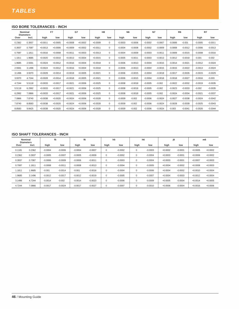
46 / Mounting Guide
ISO BORE TOLERANCES - INCHNominal F7 G7 H8 N6 N7 R6 R7
DiametersOver Incl. high low high low high low high low high low high low high low
0.2362 0.3937 +0.0011 +0.0005 +0.0008 +0.0002 +0.0009 0 -0.0003 -0.0006 -0.0002 -0.0007 -0.0006 -0.001 -0.0005 -0.0011
0.3937 0.7087 +0.0013 +0.0006 +0.0009 +0.0002 +0.0011 0 -0.0004 -0.0008 -0.0002 -0.0009 -0.0008 -0.0012 -0.0006 -0.0013
0.7087 1.1811 +0.0016 +0.0008 +0.0011 +0.0003 +0.0013 0 -0.0004 -0.0009 -0.0003 -0.0011 -0.0009 -0.0015 -0.0008 -0.0016
1.1811 1.9685 +0.0020 +0.0010 +0.0013 +0.0004 +0.0015 0 -0.0005 -0.0011 -0.0003 -0.0013 -0.0012 -0.0018 -0.001 -0.002
1.9685 2.5591 +0.0024 +0.0012 +0.0016 +0.0004 +0.0018 0 -0.0006 -0.0013 -0.0004 -0.0015 -0.0014 -0.0021 -0.0012 -0.0024
2.5591 3.1496 +0.0024 +0.0012 +0.0016 +0.0004 +0.0018 0 -0.0006 -0.0013 -0.0004 -0.0015 -0.0015 -0.0022 -0.0013 -0.0024
3.1496 3.9370 +0.0028 +0.0014 +0.0018 +0.0005 +0.0021 0 -0.0006 -0.0015 -0.0004 -0.0018 -0.0017 -0.0026 -0.0015 -0.0029
3.9370 4.7244 +0.0028 +0.0014 +0.0018 +0.0005 +0.0021 0 -0.0006 -0.0015 -0.0004 -0.0018 -0.0018 -0.0027 -0.0016 -0.003
4.7244 5.5118 +0.0033 +0.0017 +0.0021 +0.0006 +0.0025 0 -0.0008 -0.0018 -0.0005 -0.002 -0.0022 -0.0032 -0.0019 -0.0035
5.5118 6.2992 +0.0033 +0.0017 +0.0021 +0.0006 +0.0025 0 -0.0008 -0.0018 -0.0005 -0.002 -0.0023 -0.0033 -0.002 -0.0035
6.2992 7.0866 +0.0033 +0.0017 +0.0021 +0.0006 +0.0025 0 -0.0008 -0.0018 -0.0005 -0.002 -0.0024 -0.0034 -0.0021 -0.0037
7.0866 7.8740 +0.0038 +0.0020 +0.0024 +0.0006 +0.0028 0 -0.0009 -0.002 -0.0006 -0.0024 -0.0027 -0.0038 -0.0024 -0.0042
7.8740 8.8583 +0.0038 +0.0020 +0.0024 +0.0006 +0.0028 0 -0.0009 -0.002 -0.0006 -0.0024 -0.0028 -0.0039 -0.0025 -0.0043
8.8583 9.8425 +0.0038 +0.0020 +0.0024 +0.0006 +0.0028 0 -0.0009 -0.002 -0.0006 -0.0024 -0.003 -0.0041 -0.0026 -0.0044
ISO SHAFT TOLERANCES - INCHNominal f5 f6 h5 h6 j6 m6
DiametersOver Incl. high low high low high low high low high low high low
0.1181 0.2362 -0.0004 -0.0006 -0.0004 -0.0007 0 -0.0002 0 -0.0003 +0.0002 -0.0001 +0.0005 +0.0002
0.2362 0.3937 -0.0005 -0.0007 -0.0005 -0.0009 0 -0.0002 0 -0.0004 +0.0003 -0.0001 +0.0006 +0.0002
0.3937 0.7087 -0.0006 -0.0009 -0.0006 -0.0011 0 -0.0003 0 -0.0004 +0.0003 -0.0001 +0.0007 +0.0003
0.7087 1.1811 -0.0008 -0.0011 -0.0008 -0.0013 0 -0.0004 0 -0.0005 +0.0004 -0.0002 +0.0008 +0.0003
1.1811 1.9685 -0.001 -0.0014 -0.001 -0.0016 0 -0.0004 0 -0.0006 +0.0004 -0.0002 +0.0010 +0.0004
1.9685 3.1496 -0.0012 -0.0017 -0.0012 -0.0019 0 -0.0005 0 -0.0007 +0.0004 -0.0003 +0.0012 +0.0004
3.1496 4.7244 -0.0014 -0.002 -0.0014 -0.0023 0 -0.0006 0 -0.0009 +0.0005 -0.0004 +0.0014 +0.0005
4.7244 7.0866 -0.0017 -0.0024 -0.0017 -0.0027 0 -0.0007 0 -0.0010 +0.0006 -0.0004 +0.0016 +0.0006
TABLES
timken_5734mg.pm65 10/2/03, 7:27 AM46

Mounting Guide / 47
TORRINGTON SHAFT MOUNTING ACCESSORIES
HYDRAULIC NUTS
INTRODUCTIONTimken® Torrington® hydraulic nuts have been designedto install and remove tapered bore bearings with minimaleffort. The use of hydraulic nuts allows for better control ofthe bearing internal clearance reduction without damagingthe bearing or other components. Also, the hydraulic nutwill considerably reduce the downtime during installation orremoval of tapered bore bearings.
DESCRIPTIONThe Torrington hydraulic nut consists of an internallythreaded ring and an externally threaded ring with twoo-ring seals.All hydraulic nuts are supplied with:
• Quick connection fittings (external thread 1⁄4" B.S.P.and internal thread 3⁄8" N.P.T.)
• Two pipe plugs 1⁄4" B.S.P.• One set of spare o-rings.
INSTRUCTIONSWhen the hydraulic nut is used, the piston must be in theinnermost position. For this operation, please ensure thatthe valve of the hydraulic hose is disconnected from thenut so that the nut is not under pressure.
To contract the piston inside the internally threadedring, insert a rod bar in one of the four drilled holes locatedon the outside diameter of the internally threaded ring.Screw the hydraulic nut on the thread with the piston incontact with the surface until the groove machined on theoutside diameter of the piston near the outboard face islevel with the face of the internally threaded ring.
One of the two threaded holes must be plugged with the1⁄4" B.S.P. pipe plug before the hydraulic nut is pressurized.The maximum pressure permissible in the hydraulic nut is14,000 psi (100 Kpa). The oil viscosity recommended is1,400 SUS (300 cst) at operating temperature, (SAE 90oil). To avoid over extension of the piston, a second groovehas been machined on the outside diameter of the pistoninboard of the one used to judge contraction. When thissecond groove is level with the face of the internallythreaded ring, the piston has reached its length of travel asshown on the tables. If the second groove of the pistontravels past the face of the internally threaded ring, thepiston will not be correctly guided inside the threaded ringand the hydraulic nut can be damaged.
Should the oil start to leak from the piston area, it iscertain that the o-ring seals are damaged or worn andneed to be replaced.
When the hydraulic nut is not in use, ensure that thethreaded holes are plugged to prevent the entry of con-taminants in the piston cavity. To preserve againstcorrosion during storage, apply a coat of light oil on thehydraulic nut surfaces.
Installation
Hydraulic nut used to mount thebearing on a pull type sleeve.
Hydraulic nut used to mountthe bearing on taperedjournal.
Hydraulic nut used tomount the bearing on apush type adapter sleeve.
Hydraulic nut used towithdraw a push typeadapter sleeve.
Removal
ORDERING COMPONENTSContact your local Timken Sales office or nearest authorizedTimken bearing distributor for ordering Torrington hydraulic nutsystems.
ENGINEERING SERVICESSpecial applications should be referred to a Timken SalesEngineer for recommendations.
timken_5734mg.pm65 10/2/03, 7:27 AM47

48 / Mounting Guide
timken_5734mg.pm65 10/2/03, 7:27 AM48

Timken®, Torrington®, and Fafnir® are registered trademarksof The Timken Company.www.timken.com
©2003 by The Timken CompanyPrinted in U.S.A.5M-10-03-8 Order No. 5734 (formerly Torrington No. 638)
For your nearest Timken sales representative, call (800) 223-1954.Outside the U.S. and Canada, call (330) 438-3000.
WORLDWIDE LEADER IN BEARINGS AND STEEL
timken_5734mg.pm65 10/2/03, 7:27 AM50