facility and engineering controls using usp 800 · pdf filefacility and engineering controls...
TRANSCRIPT
DANGER
HAZARDOUS
CHEMICALS
DANGER
HAZARDOUS
CHEMICALS
Air�ow
52 RH71
Facility and Engineering Controls Using USP 800 Guidelines
Sponsored by
Bryan Prince, LAB RED Pharmacy ConsultantsShawn Valandra, SVE FiltrationJeremy Lundevall, Ladd Family Pharmacy
Facility and Engineering Controls Using USP 800 Guidelines
The implementation of United States Pharmacopeia (USP) General Chapter <800> “Hazardous Drugs—Handling in Healthcare Settings” is a major part of the evolution and “new normal” influencing the future of the independent compounding pharmacy and healthcare facilities that take effect on July 1st, 2018. Moving forward, the lab environments from which we will unpack, store, handle, compound, and dispose of hazardous drugs (HDs), will integrate design methods and engineering controls to minimize worker and environmental exposure to the HDs. The primary and secondary engineering control methods proposed and passed by the USP will be reliable process-safety controls if implemented, maintained and used properly.
While USP 795 and USP 797 focus on the quality of patient outcome by producing compounds of “acceptable strength, quality, and purity, and conditions to prevent contamination”, USP 800 has a more clearly defined focus specific to hazardous drug handling to “promote patient safety, worker safety and environmental protection.” In USP 795 the issue of “worker safety” was only briefly mentioned in the section on “Compounding Facilities.” The last paragraph of that section states “HDs shall be stored, prepared, and handled by appropriately trained personnel under conditions that protect healthcare workers and other personnel.” Even though this USP 795 statement is a “shall” (term that means “required”), there is still quite a bit of subjectivity with use of the phrase “under conditions” being left to individual and/or state interpretation. The clear conditions that USP 800 has defined for handling HDs is that of a “negative pressure” environment with appropriate air changes (for both sterile and nonsterile rooms) and with certain ISO considerations. The defined conditions of USP 800 do not conflict with previous chapters USP 795 or USP 797.
Like many layers of an onion, there are unanswered questions on the intricate details of USP 800-related engineering control parameters. In addition, the multitude and flexibility of the engineering controls can seem daunting to the independent pharmacy owner. Even more concerning, and certainly at the forefront of all of the independent pharmacy owners’ minds, is the cost associated with being compliant with USP 800. The costs associated with building a new facility or remodeling an existing space, are proving to be as equally subjective as the choice of engineering controls. The focus of this article is to discuss the details for consideration of a good working design of a USP 800 compliant compounding lab.
The ‘Why’ behind Negative Pressure
The original draft of chapter USP 800 was initially confusing to the independent pharmacy owner concerned as to why a “negative pressure” environment was even considered necessary in a compounding lab. The perception is that only hospitals and critical environment labs (think Centers for Disease Control) dealing with contagious and/or infectious diseases like Ebola and HIV require this type of containment environment, where no airflow can escape the room and contaminate adjacent spaces. So why should a compounding pharmacy consider negative pressure as a containment strategy? In recent years, pharmacies getting ahead of the safety curve have implemented environmental monitoring (EM) strategies on the pharmacy facility and medical surveillance programs on personnel. One very effective safety strategy was surface sampling swab tests in labs as well as common areas inside the pharmacy. Third-party testing of the wipe/swab samples revealed contamination problems both inside the lab and in more troubling general areas like break rooms and retail space. National Institute for Occupational
Safety and Health (NIOSH) studies have found similar results in compounding pharmacies throughout the U.S., which unfortunately reinforces the point.
One of the main reasons why traces of HDs and other chemicals have been discovered in common areas is because almost all sterile and nonsterile compounding labs are “positive pressure” environments. Air exchange occurs frequently from the lab to these adjoining spaces that are areas where non-lab personnel work, eat, and/or interact with customers. When powder-based chemical containers are opened, scooped from, or otherwise manipulated, the micronized particulates go airborne and are not necessarily seen by the naked eye. Every time the lab door is opened it leads to an opportunity for airborne particulates to be transferred because of pressure differentials and air exchange between rooms. In the case of a chemical spill (think bulk powder), millions of particles are airborne and have a more real potential for exchange and exposure into common areas. The only solution, in this case, is dilution and there are not enough air exchanges per hour (ACPH) to solve the particles released during the chemical spill.
The pharmacy facility’s commercial heating, ventilation, air-conditioning (HVAC) design is yet another reason for traces of contamination in common areas because it is fairly common that a retail pharmacy’s HVAC system and ductwork is shared with non-sterile compounding lab spaces. The reason why this is common is because that commercial space was not originally designed for and intended to be a chemical-handling laboratory. This type of commercial HVAC system pulls air through multiple returns located in the retail area, common spaces, and also from the lab, which then recirculates potentially contaminated air through nonexistent or inadequate filtration systems, before redistributing the air back into various areas of the facility.
So to answer the original question as to “why should a compounding pharmacy consider negative pressure” is answered in the discovery of contamination testing results, that positive pressure labs push air into general areas, and commercial HVAC systems were not designed for the purpose of chemical handling. The “what” solution to the “why” question is an engineering strategy of isolating the lab space to achieve the USP 800 chapter scope of promoting safety to patient, worker, and environment.
Containment Secondary Engineering Controls (C-SEC)
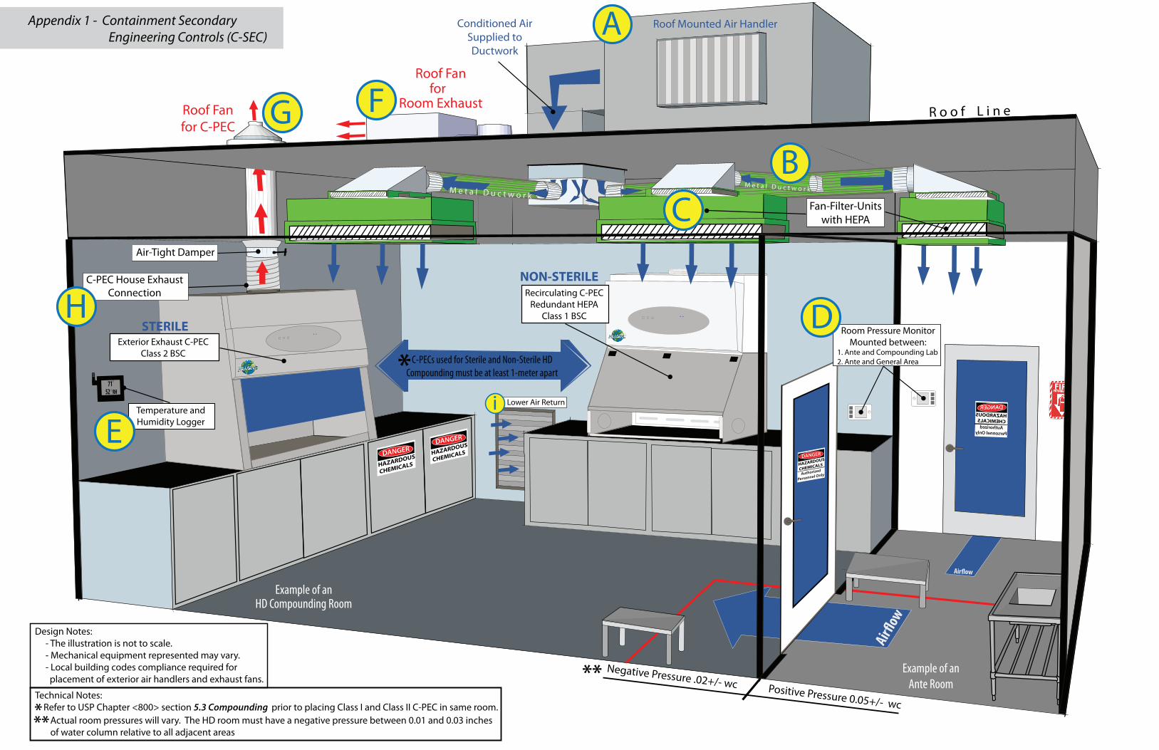
The USP 800 compliant room in which the HDs are being handled, manipulated, and/or compounded is called the Containment Secondary Engineering Control (C-SEC). The C-SEC is the room envelope equipped with engineering controls that maintain a negative pressure environment with appropriate air changes. When designing a negative pressure C-SEC there is no “one size fits all” solution, which leaves a great deal of room for discussion and interpretation. The included graphic in Appendix 1 is one such interpretation of a method to achieve HD room compliance.
The C-SEC can include, but is not limited to the following engineering controls:- Air Handling Unit (AHU) exterior-mounted for supplying conditioned air to room (see Appendix 1, Ref. A)- Duct system in interstitial space above room (see Appendix 1, Ref. B)- Fan Filter Units (FFUs) mounted in ceiling (if applicable) (see Appendix 1, Ref. C)- Differential Pressure gauges mounted on exterior wall leading into room
(see Appendix 1, Ref. D) - Temperature and Humidity gauges mounted in the room (see Appendix 1, Ref. E)- Exhaust fan exterior-mounted for room exhaust (see Appendix 1, Ref. F)- Exhaust fan exterior-mounted for Containment Primary Engineering Controls (C-PEC) (see Appendix 1, Ref. G) - Exhaust fan connection mounted inside HD room with locally controlled damper for C-PEC (see Appendix 1, Ref. H)
Achieving Negative Pressure
The HD C-SEC must maintain a “negative pressure between .01 and .03 inches of water column relative to adjacent areas.” That means that the exhaust air from the C-SEC is greater than the supply air, which will create a low-pressure vacuum from the adjoining room into the HD room. To achieve a consistent negative pressure, a dedicated AHU (Appendix 1, Ref. A) will condition outside air that will be introduced into the HD room and the return fan (Appendix 1, Ref. “F”) will pull approximately 10% - 15% more cubic feet per minute (CFM) than what is being supplied into the room. The exterior-mounted return fan satisfies the C-SEC’s “externally vented” requirement, which means the AHU system cannot recirculate any percentage of air back into the facility.
The current design of common commercial HVAC systems are mostly inadequate for maintaining USP 800’s required ACPH engineering and ISO clean air standards. Additionally, a common commercial HVAC system usually only achieves 4 to 6 ACPH. Room manipulation of airflow is done by manually opening or closing individual supply dampers located on room diffusers, which will inevitably create a difficult balancing act between all rooms that share ductwork. Manually closing one supply damper will push that air pressure through the ductwork to be distributed to another supply because the constant volume of air coming from the HVAC does not change. The main point here is that the pharmacy trying to save money by reconfiguring their current commercial HVAC system is likely to fail.
Comparing methods: Constant Air Volume systems versus Variable Air Volume Systems
Negative pressure environments requiring air to dilute contaminates, with low cooling loads, and consisting of only a few C-PECs are sometimes referred to as “ventilation-driven.” A Constant Air Volume (CAV) system has been traditionally viewed as the best method for ventilation-driven environments because ACPH requirements drive the air-volumes. CAV systems are simple in design and have fewer controls to maintain. Some CAV systems are capable of adding simple monitors (e.g. Differential Room Pressure Monitors) and/or automated controls for data logging to better manage and document the pharmacy’s HD program, but with certain limitations such as off-peak scheduling. If the CAV system’s capacity is also limited in demand for future needs such as the HD room expansion/relocation or connecting additional C-PECs.
In comparison to CAV systems, larger facilities with multiple C-SEC rooms (or facility sections called “zones”), all with varying temperature and humidity demands, are integrating somewhat more complex Variable Air Volume (VAV) systems because of their unique ability to reduce or increase air volumes for consistent room balancing in different zones. Properly controlled VAV systems will work to reduce energy consumption by reducing air volumes to minimum
requirements. Logic controls can be integrated to C-PECs, airflow pressure monitoring, as well as off-peak scheduling (e.g. room unoccupied status, night and holiday set-backs) just to name a few. VAV systems are typically more expensive than CAV and the complexity of the control integration add long-term maintenance concerns.
Fan Filter Units
Fan Filter Units (FFUs) are common engineering solutions used in USP 797 cleanroom design. Integration of FFUs as engineering controls into the ceiling of the sterile and/or nonsterile HD room (Appendix 1, Ref. “C”) will better manage air quality and the ACPH demand. Just as the name implies, the FFU contains a positive pressure fan that is receiving air from the roof-mounted AHU through ductwork. The FFUs then push that air through a HEPA filter (for ISO 7 requirements) directly into the HD room.
Because FFUs have easily accessible HEPA filters, the HEPA filter integrity scan will make room certification easier to achieve. FFUs are low-voltage and energy efficient that control fan speed individually by potentiometers (for small rooms), or daisy-chained in a series and being balanced by one master control (for larger rooms). The FFUs can be connected to or integrated into CAV or VAV systems. The FFU fans don’t cause much push pull as they are only designed to overcome the HEPA filter pressure drop, which makes FFUs easier to balance.
Ductwork
Commercial flex duct can be considered inadequate for two reasons 1) static pressure losses that are associated with flex hose and 2) any minor penetration in the duct can allow particles in from the interstitial space above the lab’s ceiling or anywhere along the path from the AHU. If the commercial flex duct, which is under negative pressure from the interstitial space, allows any particles in, then an HD room with HEPA filter supply air from the AHU will likely fail Certification. More explanation of Certification is in section “Test and Balance the C-SEC.”
Instead of commercial flex duct, the alternative is galvanized metal or stainless steel ductwork (Appendix 1, Ref. “B”) with welded seams that prevent leaks and particles from entering, providing a better long term solution. Metal ductwork is more expensive and could present a cost challenge depending on how much ductwork is required. However, the advantage of using metal ductwork is that it can also be easily uninstalled and cleaned if there is a filter breach on the air handling unit. Combining metal ductwork with HEPA filtered air from FFUs is the best case scenario for maintaining long term ISO standard success.
Differential Pressure Monitor
Integrating a visual monitor that measures and displays the differential pressure between the HD room (buffer area) and its adjoining space (ante-area) is clearly stated in USP 797 and clearly implied in USP 800. In a sterile HD room, there should be a visual monitor between the buffer area and ante area, and between the ante area and the adjoining space that leads into the general pharmacy environment (Appendix 1, Ref “D”). The ante area’s monitors should display positive pressure between both the buffer and adjoining space. Reviewing and
documenting the pressure monitors’ data daily applies to both sterile and nonsterile environments.
Room Air Change Measurements
The USP 800 chapter requires twelve “air changes per hour” (ACPH) in a Non-sterile HD room and thirty ACPH in a Sterile HD room. ACPH are the number of times air is replaced in the room’s total cubic square footage (ft3) in one hour. To determine the amount of supply air (CFM) to achieve the C-SECs required ACPH, the equation is this: CFM = (ft3 X ACPH) / 60
Example of calculating two different room’s supply CFM to satisfy the sterile ACPH requirement: Room #1 HD Room Size: 12’ wide X 12’ deep X 9’ tall = 1296 ft3
CFM = (1296 X 30) / 60 CFM = 648
Room #2 HD Room Size: 10’ wide X 10’ deep X 9’ tall = 900 ft3
CFM = (900 X 30) / 60 CFM = 450
Now to continue these two room examples we are going to include the Class II C-PECthat is externally exhausting 550 CFM out of the room. To determine if more air is needed at the supply for balance or required by a low wall exhaust return, the equation is this: Supply CFM minus C-PEC exhaust CFM
Room #1: 648 - 550 = + 98 (CFM supply surplus)Room #2: 450 - 550 = -150 (CFM supply shortage)
Room #1 - The C-SEC is supplying 98 more CFM than what the C-PEC is exhausting.In the section above “Achieving Negative Pressure” we established that exhaust CFMhas to be approximately 15% higher than supply CFM to achieve a negative pressureroom. The equation to determine how much exhaust air required is this:
Supply CFM plus 15%648 x 1.15 = 745.20 total exhaust CFM to achieve 30 ACPH
A low air return (Appendix 1, Ref “i”) will allow the surplus supply air (745 - 550 = 195 CFM) to exhaust out of the building, pulled by the exterior-mounted exhaust fan(Appendix 1, Ref. F).
Room #2 - The C-PEC is exhausting more CFM than what is being supplied. The C-PEC is now providing 100% of the sterile room’s external exhaust requirements (nolow air return required). Additional CFM is required at supply to compensate for the shortage.
Total Exhaust CFM minus 15%600 x .85 = 510 total supply CFM to achieve 30 ACPH
Temperature and Humidity
Factors that affect the temperature inside the HD room are concentrations of people, room lighting, and lab equipment. Those three factors influence the demand on a HVAC system to maintain the room’s target temperature and should be accounted for during the design phase of the HD room. The Pharmacy’s geographic location and local climate should influence the design and demand of an AHU in an effort to condition. Good examples are Southern geographic regions where higher temperatures and relative humidities are prevalent for longer periods of the year. The AHU design criteria will certainly need to integrate appropriate controls to remove moisture from the outside air to consistently condition down to HD room temperature and humidity targets.
Although the USP 800 chapter does not define specific parameters for monitoring temperature and humidity, there are many other chapter references in the USP Compounding Compendium about room temperature, as well as new targets set in the revised USP 797 chapter. If there is a question involving HDs and room temperature with assigning Beyond Use Dates (BUD), stability, storage, repackaging, shipping, etc., an internal search of the USP Compounding Compendium’s digital PDF will supplement the answer to the questions. It is always considered a best practice to monitor these conditions within a sterile and nonsterile compounding lab.
From a quality control (QC) perspective, additional heat can equate to a higher relative humidity in a lab that can add additional moisture content to a formulation, possibly change particle size, and formulation consistency. Lab equipment generating consistent heat or that serves as a combustion resource (such as autoclaves) should be isolated away from HD compounding. Also considering the HD lab is negative in relation to the rest of the facility, it is possible that occasional transference of humidity can exchange during opening and closing of the negative pressure compounding lab. This is especially true in a nonsterile HD room with no ante or buffer between lab and common areas. Conversely, a lab environment too dry can facilitate static electricity and make weighing and manipulating fine powders more difficult, causing the micronized particulates to go airborne. These dynamic pharmacy facility conditions prove the case for monitoring temperature and humidity in the HD room.
The logging of the information can be a simple manual solution or a more sophisticated automated solution. The most inexpensive solution, one we have recommended quite often in USP 795 labs nonsterile compounding labs, is a $15 hygrometer which simply serves as an active visual of temperature and relative humidity in the lab. A good daily practice is for the lab manager (or designated safety lead) to manually log the temperature and humidity on a designated QC form. It is another daily task, but one that is quick and has very low time impact. A more sophisticated solution (around $500) that requires no manual or daily interaction is a data logger connected to the facility’s wireless network and mounted on the lab wall (Appendix 1, Ref. “E”). The data from the logger is transmitted to an online cloud account, with email and/or text alerts to designated personnel when temperature or humidity gets out of range.
Regardless of the logging-solution method, the designated lead for your pharmacy ’s HD program can use the valuable data in QC reporting and reportable incidents. Any incident involving HD formulations, such as patient complaints or contamination, treat the situation just like USP 797’s “adverse-events and incident reporting program.” Furthering the pharmacy’s QC commitment to patient quality and USP standards, implementing a regular testing schedule of sending preparation samples to a third party analytical lab is advantageous.
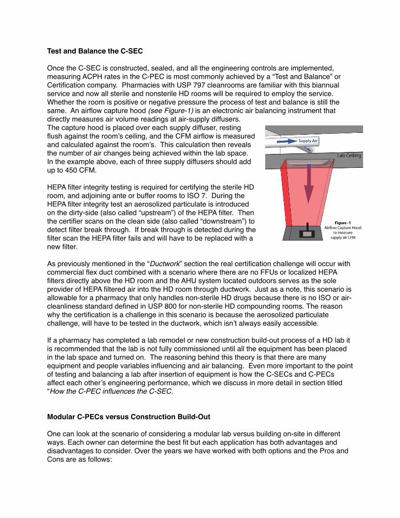
Test and Balance the C-SEC
Once the C-SEC is constructed, sealed, and all the engineering controls are implemented, measuring ACPH rates in the C-PEC is most commonly achieved by a “Test and Balance” or Certification company. Pharmacies with USP 797 cleanrooms are familiar with this biannual service and now all sterile and nonsterile HD rooms will be required to employ the service. Whether the room is positive or negative pressure the process of test and balance is still the same. An airflow capture hood (see Figure-1) is an electronic air balancing instrument that directly measures air volume readings at air-supply diffusers. The capture hood is placed over each supply diffuser, resting flush against the room’s ceiling, and the CFM airflow is measured and calculated against the room’s. This calculation then reveals the number of air changes being achieved within the lab space. In the example above, each of three supply diffusers should add up to 450 CFM.
HEPA filter integrity testing is required for certifying the sterile HD room, and adjoining ante or buffer rooms to ISO 7. During the HEPA filter integrity test an aerosolized particulate is introduced on the dirty-side (also called “upstream”) of the HEPA filter. Then the certifier scans on the clean side (also called “downstream”) to detect filter break through. If break through is detected during the filter scan the HEPA filter fails and will have to be replaced with a new filter.
As previously mentioned in the “Ductwork” section the real certification challenge will occur with commercial flex duct combined with a scenario where there are no FFUs or localized HEPA filters directly above the HD room and the AHU system located outdoors serves as the sole provider of HEPA filtered air into the HD room through ductwork. Just as a note, this scenario is allowable for a pharmacy that only handles non-sterile HD drugs because there is no ISO or air-cleanliness standard defined in USP 800 for non-sterile HD compounding rooms. The reason why the certification is a challenge in this scenario is because the aerosolized particulate challenge, will have to be tested in the ductwork, which isn’t always easily accessible.
If a pharmacy has completed a lab remodel or new construction build-out process of a HD lab it is recommended that the lab is not fully commissioned until all the equipment has been placed in the lab space and turned on. The reasoning behind this theory is that there are many equipment and people variables influencing and air balancing. Even more important to the point of testing and balancing a lab after insertion of equipment is how the C-SECs and C-PECs affect each other’s engineering performance, which we discuss in more detail in section titled “How the C-PEC influences the C-SEC.
Modular C-PECs versus Construction Build-Out
One can look at the scenario of considering a modular lab versus building on-site in different ways. Each owner can determine the best fit but each application has both advantages and disadvantages to consider. Over the years we have worked with both options and the Pros and Cons are as follows:
Modular - In the independent pharmacy, modular cleanrooms have historically been reserved for positive pressure design and USP 797 sterile compounding activities. Most cleanroom manufacturers also offer a negative pressure custom pre-fabricated room that can be built offsite to design specifications determined by the owner and contractor.
Pros- Modular rooms offer a very nice finish, pleasing look and are engineered and designed specifically for the purpose of containment. All surfaces are designed to be easily cleanable and without cracks. The ability to move the modular room and/or add on to the room has minimal impact to the business, especially with a pharmacy located in a commercial shopping center, or a medical mall area, when the owner of the pharmacy is not the owner of the property on which the business resides. Businesses can relocate or reconfigure as this room can be disassembled and moved in its entirety. One of the biggest benefits is that modular rooms, in most cases, will have a guarantee to pass certification by the seller, which is important documentation proving compliance.
Cons- Cost of a custom-designed room can be significantly higher. Lead time can be longer if ordering a room and you need it sooner than later, due to manufacturing lead and shipping schedules. The aesthetic look (metal-framed) will not typically match the pharmacy’s current store design.
Build Out- These are custom rooms completed on-site by your contractor. A build out is generally more common if you own the building and are not looking to move because your pharmacy is established in the community. Build Out rooms are achieved by taking your existing space and working towards meeting the requirements by using the provided space and in some cases tying into the current infrastructure systems like electrical, plumbing, and in some cases HVAC.
Pros – Can be less costly since you can use some of your surrounding area along with supply lines for electrical, plumbing, and HVAC (on some occasions). Interestingly enough, build out can usually be completed in less time than a modular due to lead extended times by offsite modular manufacturers. Build out also offers more flexibility with choosing building materials like flooring and cabinetry, which means the rooms will match current store designs and aesthetically look like the room always existed.
Cons – On-site construction is the most impactful to day-to-day operations and the internal/infrastructure remodeling can disrupt compounding production, especially if there is not a temporary space designated for compounding. Temporary spaces require a lot of equipment moving and larger sterile C-PECs are difficult to move (and require additional certification after being moved). Once the USP 800 compliant ante and compounding room are built, pharmacy facilities with already limited space lose additional flexibility for growth down the road if expansion needs to happen. Local contractors don’t normally understand USP compliance requirements or our industry’s best practices for facility design. It is also likely the contractor will not offer any certification guarantees to meet USP criteria which can cost you down the road if the room(s) don’t pass as expected.
Containment Primary Engineering Control (C-PEC)
The primary engineering control purpose is to provide containment during compounding and manipulation of hazardous drugs. For decades we have generically known and referred to C-PECs as “hoods”. In a non-sterile HD lab, the USP 800 Chapter states that the C-PEC “should” be externally vented (meaning recommended), but a C-PEC with redundant-HEPA filtration is acceptable. By contrast, in a sterile HD lab, the chapter states the C-PEC “shall” be externally vented with no option for recirculation. In the following section we will dissect the differences in approved C-PECs and explain the ventilation options. Further explanation of USP 800’s C-PEC requirements is available in Appendix 2.
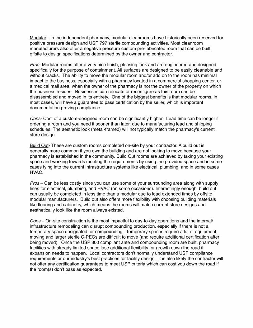
A Class 1 Biological Safety Cabinet (BSC) or a Containment Ventilated Enclosure (CVE) is very simply a negative pressure hood (commonly called a “powder hood”) that provides personnel protection. There are no major distinctions between the three terminologies and so the Class 1 BSC, CVE, and powder hood can be considered interchangeable descriptions. Both the Class 1 BSC and CVE have “one-pass air” that exhausts one-hundred percent of the air pulled in through the face opening. Prior to exhausting, the air passes through a HEPA filter, and in some cases, an additional carbon filter. If your pharmacy currently has one or many C-PECs in place, it is more likely equipped with only a single layer of primary HEPA filtration. If the pharmacy is going to utilize the current inventory of hoods in the HD room, then a house exhaust connection will be required (see Appendix 1, Ref. G and H). The C-PEC to house exhaust connection details are discussed in the section titled “How the C-PEC influences the C-SEC Requirements.”
A Class 2 BSC provides both product and personnel protection because there is a percentage of clean air recirculated through the internal filter system and blanketed down onto the hood’s work surface. Class 2 are approved C-PECs for use in nonsterile and sterile HD compounding rooms and are required to be connected to a house exhaust system.
Worthy of mentioning and contrary to popular belief, merely installing, certifying, and compounding inside of a C-PEC of any type or class does not guarantee “environmental protection” from exposure as the chapter implies. The C-PEC is an effective engineering control but exposure to the room environment and personnel can and will occur in the absence of good lab practices (GLP) while interacting with the C-PEC. There is a very important correlation between the C-PEC and GLP if USP 800’s true intent of limiting personnel exposure to HDs is to be achieved.
What is meant by “Redundant Filtration”?
C-PECs with redundant HEPA filtration means both HEPA filters share the same exhaust downstream (See Figure-2). Class 1 C-PECs with redundant filtration are more expensive pieces of equipment and therefore require a larger upfront capital expense outlay. However, in a preliminary cost comparison of purchasing a redundant HEPA C-PEC versus installation of a dedicated roof fan to exhaust a C-PEC, it is less expensive to purchase the redundant filtration C-PEC.
A recirculating C-PEC is considered “room neutral”. This means the same amount of air pulled in through the front face opening of the C-PEC is equal to the CFM exhausted back in the room, so no additional CFM is required from the facility’s air handling system for room balance. The

cost savings comes from the redundant HEPA recirculating clean filtered air back into the non-sterile HD room without use or need of additional engineering controls mounted on the roof of the facility. The additional cost of installing requires hiring a contractor to purchase, install, wire, and connect a roof fan to the C-PEC. In addition to the construction cost, there is a cost associated with constantly replacing the air that the C-PEC sends out of the building. In certain geographic regions and seasons, conditioning outdoor air for use in the HD room is expensive from an energy consideration point-of-view. Saving energy consumption in the long run will payback the upfront capital expense.
Although a BSC Type II hood typically has two HEPA filters, they are not considered redundant because only one HEPA filter is in the direct exhaust downstream. The other HEPA filter is for the purpose of recirculating air back onto the hood’s interior work surface. So understand that the term “redundant” filtration is not the number of filters inside the C-PEC, but whether or not the air is being double-filtered prior to exhaust.
As a mere professional opinion, not confirmed in any USP chapter, a C-PEC with a HEPA pre-filter and a HEPA primary filter in the same downstream should not be considered redundant filtration. Pre-filters have smaller pleat depth and lower efficiency ratings than the primary filter. Pre-filters are placed inside the interior working space of the hood, located either behind over directly over the work surface, which could potentially lead to cross-contamination. As particulates agglomerate on the pre-filter particles can fall down on the work surface because the negative static charge can no longer adequately capture and hold the particles on the filter media. This principle is especially true if the hoods are powered off and there is no longer a negative pressure. Pre-filters are considered disposable short-term filtration solutions that require additional maintenance and handling from the pharmacy staff. The easily accessible pre-filters are cross-contaminated with different types of chemicals, all with varying levels of exposure and associated health risks. To further reinforce the point, primary HEPA filters are never handled or disposed of by pharmacy staff. Certifiers that are trained on safety protocols and donned in proper Personal Protective Equipment (PPE) are the only ones handling and disposing of primary filters. So the case stands to reason that the pharmacy should not take on additional risk consistently handling disposable pre-filters.
How the C-PEC influences the C-SEC
In a sterile HD room, the C-PEC is required to be exhausted out of the building and this achieved with a dedicated roof fan (Appendix 1, Ref. “G”). The C-PEC is connected to the roof fan by a thimble and/or canopy connection based manufacture’s requirements (see Figure 3). The roof fan for the C-PEC will have to pull 10% - 15% more CFM than what is being exhausted by the C-PEC to make sure the hood remains negative. As an example, if the C-PEC is exhausting 300 CFM, then the roof fan will have to pull approximately 330 - 350 CFM. Balance
is more easily achieved during certification if a local damper control is present and highly recommended as an engineering control.
As witnessed in the section “Room Air-Change Measurements” the C-PEC acting as a room exhaust engineering control changes the total supply CFM required to balance the room. As additional C-PECs are added to the HD room the amount of total supply air required for balance will increase as well, so anticipation of adding additional equipment is a wise decision during the planning phase.
How the C-SEC influences C-PEC
In the early phase of lab design planning we consider “workflow” and equipment placement as primary concerns. The term “workflow” is how people and processes move in and around the lab space to achieve production. People are actively participating in the workflow process that requires them to move in, around, and out of the room, which have varying levels of impact on airflow patterns.
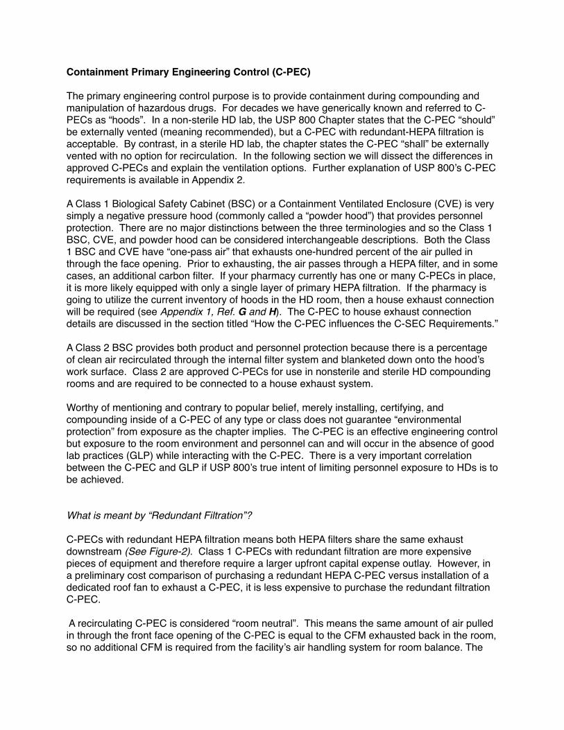
To better understand the importance of the airflow concept, first understand there are two types of airflow: turbulent and laminar. HVAC supply air into the room is considered turbulent, swirling and/or with varying velocities. The C-PEC is taking turbulent room air and “smoothing” it to laminar air as it is introduced into the front face opening. The laminar air then travels in a horizontal low-flow pattern inside the C-PEC as not to disrupt compounding processes (e.g. weighing powders on an analytical scale). When a technician is handling HD chemicals inside of a C-PEC, other technicians should greatly limit the amount of movement around the C-PEC, which creates additional room air turbulence. The C-PEC is a very important engineering control for personnel and environmental safety and should be respected as such. A Standard Operating Procedure (SOP) should be written that states, “during active HD compounding, doors are to remain closed and personnel movement should be limited.” During lab planning, analyzing and mapping workflow processes will aid in the lab design process to better stabilize the workflow environment.
Containment performance of the C-PEC can be further achieved by placing the C-PEC away from doors and busy traffic patterns. During our site visits we have noticed that pharmacies have done well with trying to isolate the C-PECs, but oftentimes this incurs the C-PEC to be placed into a corner. In nonsterile labs the Class I hoods are exhausting air straight up towards the ceiling creating a turbulent spread. Some of the air then runs down the diverging corner and rolls back in front of the hood’s face opening (see Figure-4 on previous page). Avoid placing the C-PECs against diverging walls whenever possible.
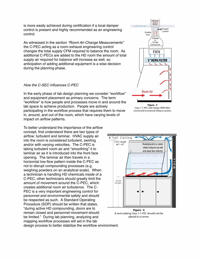
During the design phase, consideration for placement of supply diffusers or FFUs is very important in direct relation to the placement of C-PECs. The two engineering controls are trying to achieve an important purpose and conflict between the two can occur. Supply air enters the C-SEC through diffusers at 100 to 300 CFM. The supply air is turbulent and when placed directly over a C-PEC, can disrupt the air coming into the C-PEC’s face opening (see Figure-5). The vertical supply air can shear off the horizontal air, creating inconsistent face velocities on the C-PEC. Offsetting the FFUs (or supply diffusers) four to six feet on the ceiling’s horizontal plane is a good rule of thumb for avoiding this situation.
Summary: Pharmacy owners are entrepreneurs and their daily consideration of cash flow is always at the forefront of a business owner’s mind. Some of the engineering capital solutions required by USP 800 and review here will require a more expensive up-front capital investment to satisfy infrastructure demands, but financial considerations of payback-period and “cost of ownership” should also be examined. Researching and implementing more energy efficient equipment such as C-PECs with ultra high efficiency motors require less energy consumption, in turn extending HEPA filter life which reduces frequency of replacement. So the major point is to be more concerned about longevity and be less intimidated by the initial investment required to design and operate a safe and efficient USP 800 compliant lab.
Also consider that not all of the engineering controls recommended in this paper are mandated by the USP and may seem above and beyond the recommendation of the USP 800 requirements. However, we have offered “best practices” whose intent is to create a safe working environment for the people we employ. The ideas in this paper also reflect holistic ideas of safety and quality that ultimately benefit the pharmacy's employees as well as patient outcome.
As a disclaimer, this information is intended to clarify only a limited scope of engineering controls when considering the multitude of commercial products in the market. Our main intent is to clarify engineering principles and assist the management in compounding pharmacies and healthcare facilities to demystify the process and have informed discussions with contractors and manufacturers that supply products. We make no claims as to the final interpretations from regulatory organizations such as the State Boards of Pharmacy (BOP) and/or the FDA, and/or OSHA. Additionally we make no claims on final interpretation of policy recommendations from
the United States Pharmacopeia (USP) and/or accreditation organizations such as the Accreditation Commission for Health Care (ACHC/PCAB).
———————————————————————
Author:
Bryan Prince, MBA is the owner and lead consultant at Lab·Red Pharmacy Consultants (website: http://pharmacyworkflow.com/) His early career in containment technology allowed him access to pharmaceutical labs around the U.S. where he gleaned extensive knowledge of chemical handling technique and safety strategies. In 2012 he started visiting compounding pharmacies to observe workflow habits and share his knowledge, which led to writing articles for the International Journal of Pharmaceutical Compounding (IJPC). Bryan has been invited to speak at conferences on “Quality, Safety, and Workflow in the Compounding Pharmacy” for the American College of Apothecaries and PCCA. He has also contributed to the ACHC as an Expert Panelist on a series of USP 800 webinars. email: [email protected]
Contributing Authors:
Shawn Valandra is an Environmental Filtration Consultant and owner of SVE Industrial Air Filtration Solutions based in Phoenix, AZ. He has two decades providing clean air solutions to commercial and industrial facilities. Shawn has provided air handling design solutions to multiple compounding pharmacies for USP 800 compliance.
Jeremy Lundevall, CPhT is the Operations Manager and Partner at Ladd Family Pharmacy in Boise, ID. He has worked in various roles within the pharmacy industry for 20+ years. Jeremy is a former Trainer/Consultant for PCCA, has spoken at conferences on pharmacy operations and co-authored articles for the IJPC.
DANGER
HAZARDOUS
CHEMICALS
DANGER
HAZARDOUS
CHEMICALS
Roof Fan for C-PEC
Roof Fan
Room
Exh
aust
R o o f L i n e
Air�ow
Recirculating C-PECRedundant HEPA
Class 1 BSC
NON-STERILE
C-PECs used for Sterile and Non-Sterile HD Compounding must be at least 1-meter apart
Negative Pressure .02+/- wc Positive Pressure 0.05+/- wc
C-PEC House Exhaust Connection
Example of an Ante Room
Exterior Exhaust C-PECClass 2 BSC
STERILE
52 RH71
Temperature and Humidity Logger
Roof Mounted Air HandlerConditioned Air Supplied to Ductwork
HD Compounding Room
Fan-Filter-Units with HEPA
Air-Tight Damper
M e t a l D u c t w o r kM e t a l D u c t w o r k
Design Notes: - The illustration is not to scale. - Mechanical equipment represented may vary. - Local building codes compliance required for placement of exterior air handlers and exhaust fans.
Room Pressure Monitor Mounted between:
1. Ante and Compounding Lab2. Ante and General Area
Appendix 1 - Containment Secondary Engineering Controls (C-SEC) A
BC
E
D
G F forRoom Exhaust
H
Example of an
DANGERHAZARDOUSCHEMICALS
Authorized Personnel Only
DANGER
HAZARDOUS
CHEMICALS
Authorized
Personnel Only
Air�ow
*
Technical Notes: Refer to USP Chapter <800> section 5.3 Compounding prior to placing Class I and Class II C-PEC in same room. *
**
Actual room pressures will vary. The HD room must have a negative pressure between 0.01 and 0.03 inches of water column relative to all adjacent areas
**
Lower Air Returni

Appendix 2Consolidated Chart of Primary and Secondary Engineering Controls
Nonsterile HD RoomSterile HD Room Containment Segregated
Compounding Area (C-SCA)Ante Room Buffer Room
Containment Secondary Engineering Controls (C-SEC)
Air Changes Per Hour (ACPH) >12 ACPH >30 ACPH >30 ACPH >12 ACPH
Room Ventilation Externally Vented N/A Externally Vented Externally Vented
Room Pressure Negative 0.01 - 0.03 " water with respect to adjacent areas Positive to Buffer
Negative 0.01 - 0.03 " water with respect to adjacent
areas
Negative 0.01 - 0.03 " water with respect to adjacent areas
Air Class N/A ISO 7 ISO 7 N/A
Sink Placement >1 meter away from C-PEC 1 meter from buffer room entrance
Not Allowed >1 meter away from C-PEC or located directly outside C-SCA
Walls Fixed, Smooth, Impervious Fixed, Smooth, Impervious, Complies with USP 797
Fixed, Smooth, Impervious, Complies with USP 797 Fixed, Smooth, Impervious
Beyond-Use Date (BUD) Based on earliest date of combined compounds N/A >12 hours <12 hours
Compounded Sterile Preparations (CSPs) Not Allowed Not Allowed Category 1 and 2 CSPs Low and medium risk HD CSPs
Containment Primary Engineering Controls (C-PEC)
Class 1 BSC/CVE - Single HEPA Filtration Externally Vented Not Allowed Not Allowed Externally Vented
Class 1 BSC/CVE - Redundant HEPA Filtration Externally Vented Preferred; Recirculation Allowed Not Allowed Not Allowed Externally Vented Preferred;
Recirculation Allowed
Class 2 BSC (Types A2, B1, or B2) - ISO Class 5 Externally Vented Not Allowed Externally Vented Externally Vented
Compounding Aseptic Containment Isolator (CACI) Externally Vented Not Allowed Externally Vented Externally Vented