facial fracture beyond le fort
DESCRIPTION
Maxilla fractures article.TRANSCRIPT
Otolaryngol Clin N Am
Facial Fractures: Beyond Le Fort
Rebecca E. Fraioli, MDa,Barton F. Branstetter IV, MDa,b,
Frederic W.-B. Deleyiannis, MD, MPhil, MPHa,c,*aDepartment of Otolaryngology, University of Pittsburgh Medical Center,
Eye and Ear Institute, 203 Lothrop Street, Suite 500, Pittsburgh, PA 15213, USAbDepartment of Radiology, University of Pittsburgh Medical Center,
200 Lothrop Street, Pittsburgh, PA 15213, USAcDivision of Plastic Surgery, Departments of Surgery and Otolaryngology,
University of Pittsburgh Medical Center, 6B Scaife Hall, 3550 Terrace Street,
Pittsburgh, PA 15261, USA
The management of facial fractures begins with the establishment of anaccurate fracture diagnosis. All too often, radiology reports contain a ‘‘laun-dry list’’ of fractures without clinical context, without an understanding offracture patterns, or without categorization by fracture severity, fracturecriticality, or the need for surgical repair. For example, a radiology reportthat focuses on nasal septal fractures, but ignores a medial canthal avulsion,can be annoying or even misleading to the surgeon.
Fracture complexes are reproducible, and the terminology of fracturecomplexes allows for efficient communication between physicians of intri-cate fracture patterns in the midface. This type of communication requiresthat the radiologist understand common mechanisms of injury and the frac-ture complexes that result.
The best-known categorization scheme for fracture fractures is that ofRene Le Fort. However, Le Fort’s work was based on low-speed impact,and does not completely reflect the breadth of trauma that is encounteredin modern medicine. The purpose of this issue is to provide a broader clas-sification scheme for midface fracture complexes, which incorporates, andyet goes beyond, Le Fort’s classification. The goal is to encourage more clin-ically relevant radiology reports, so that surgeons will know what to expect,and radiologists will know what to provide, in the CT evaluation of facial
41 (2008) 51–76
* Corresponding author. Division of Plastic Surgery, Departments of Surgery and
Otolaryngology, University of Pittsburgh Medical Center, 6B Scaife Hall, 3550 Terrace
Street, Pittsburgh, PA 15261.
E-mail address: [email protected] (F.W.-B. Deleyiannis).
0030-6665/08/$ - see front matter � 2008 Elsevier Inc. All rights reserved.
doi:10.1016/j.otc.2007.10.003 oto.theclinics.com

52 FRAIOLI et al
fractures. Variables that affect surgical management will be emphasized. Atthe end of each section, there is a short list of pearls for creating clinicallyrelevant radiology reports.
This issue is focused on midface fractures; mandibular and skull basefractures are intentionally excluded to retain this focus.
Frontal sinus fractures
Fractures of the frontal sinuses comprise about 5% to 15% of maxillofa-cial fractures [1–3]. These fractures are generally classified by involvement ofthe anterior wall (anterior table) or posterior wall (posterior table). In addi-tion, fractures of either wall may be comminuted or noncomminuted, anddisplaced or nondisplaced. Finally, involvement of either the nasofrontalduct or the anterior cranial fossa dura has important implications for theclinical management of these fractures.
The importance of the radiologic diagnosis of frontal sinus fractures isunderscored by the fact that before the advent of routine CT scanning forhead trauma, 50% of frontal sinus fractures were not identified until afterthe patient had left the emergency room [4]. The frontal bone is the strongestof the facial bones, and a large amount of force (800 to 2200 lb) is requiredto fracture the frontal sinuses [5]. The presence of frontal sinus fracturesmay therefore be considered an indicator of a high-force injury, and shouldalert the physician to search for other injuries. Additional craniofacialinjuries are present in 56% to 87% of patients with frontal sinus fractures[4,6–11]. An associated cerebrospinal fluid (CSF) leak is present in 13%to 33% of patients with frontal sinus fractures [4,6,8,10,12]. Mortality sec-ondary to other associated injuries has been reported at rates of approxi-mately 9% of patients with frontal sinus fractures [6].
Structures involved
Each wall of the frontal sinus serves a dual function. The anterior wall ofthe frontal sinus, formed by the frontal bone, is responsible for the aestheticcontours of the forehead and the superior orbital rims. In addition, thisstructure serves as the frontal bar, one of the key horizontal buttresses ofthe facial skeleton (Fig. 1). The frontal bar helps to maintain the horizontaldimension of the face and to provide a stable foundation for the verticallyoriented facial buttresses (see Fig. 1) that support the forces of mastication.Fractures of the anterior table may be clinically important either by disrupt-ing the aesthetic contour of the forehead or by destabilizing the frontal barfrom which the other facial bones are suspended [13]. The posterior wall ofthe frontal sinus forms the anterior wall of the anterior cranial fossa, andserves to separate the sinus contents from the cranial vault. Posterior tablefractures are therefore skull fractures, and must be recognized and managedas such. The floor of the frontal sinus forms the medial orbital roof; it also

Fig. 1. The buttress system of the midface. The buttress system of the midface is formed by the
strong frontal, maxillary, zygomatic, and sphenoid bones and their attachments to one another.
The central midface consists of several fragile bones that easily ‘‘crumple’’ when subjected to
strong forces. These more fragile bones are surrounded by the thicker bones of the buttress
system, which provide structure and absorb the forces applied to the face. Most of the forces
absorbed by the face are masticatory, therefore the vertical buttresses are the most well devel-
oped. These include the medial nasomaxillary buttress and the lateral zygomaticomaxillary but-
tress. Three horizontal buttresses interconnect and provide support for the vertical buttresses:
the frontal bone and supraorbital rims (frontal bar), the nasal bones and inferior orbital
rims, and the maxillary alveolus. (From Linnau KF, Stanley RB Jr, Hallam DK, et al. Imaging
of high-energy midfacial trauma: what the surgeon needs to know. Eur J Radiol 2003;48:17–32;
with permission.)
53FACIAL FRACTURES
houses the ostium to the nasofrontal duct in its posteromedial aspect [9].The nasofrontal duct forms the drainage pathway of the frontal sinus intothe nose, so obstruction of this pathway can lead to mucocele, mucopyocele,osteomyelitis, and epidural or subdural abscess [12].
Variables affecting treatment
There are three main variables to consider when assessing the need forsurgical intervention for frontal sinus fractures. These are involvement ofthe anterior table, disruption of the nasofrontal duct, and involvement ofthe posterior table. When assessing the involvement of the anterior or pos-terior tables, the degree of fracture displacement and comminution are alsoimportant. An additional factor involved when assessing the posterior tableis the likelihood of dural penetration or nasofrontal duct disruption.

54 FRAIOLI et al
Anterior table fractures
Nondisplaced anterior table fractures require no surgical intervention.Displaced anterior table fractures may cause cosmetic deformity becauseof facial stepoffs, asymmetry, or flattening of the normally convex glabella.Repair of these defects is ideally performed within 10 days of the injury,a time during which soft tissue edema resulting from the trauma may maskthe cosmetic deformity. Consequently, radiologic estimates of the degree ofdisplacement of the anterior table and the resultant cosmetic deformity arecritical in making the determination of whether to proceed with surgery.
Posterior table fractures
The management of posterior table fractures remains somewhat contro-versial. Nondisplaced posterior table fractures are frequently treated conser-vatively with close follow-up [2,11]. Follow-up should include early andrepeated CT scans of the sinuses [3,11]. In contrast, comminuted ordisplaced posterior table fractures are generally felt to increase the risk ofcomplications and thus merit exploration [3,14]. The presence of pneumoce-phalus, although not specific, may indicate dural violation, and also may bean indication for surgical exploration of the fracture [14]. Posterior tablefractures may be managed with sinus obliteration if the floor of the sinusis not comminuted and there is not a large amount of bone missing(Fig. 2). Severely comminuted or displaced posterior wall fractures fre-quently require cranialization (Fig. 3) [6,14,15].
Involvement of the nasofrontal duct
If the nasofrontal duct is disrupted, operative intervention is necessary.A few recent reports suggest that conservative management with an endo-scopic Lothrop procedure when necessary to reestablish the frontal sinusdrainage pathway may be an option; however, the most trusted methodof management is to obliterate the sinus and nasofrontal duct ostium[11,16–19]. Disruption of the nasofrontal duct may be difficult to assesson CT, and intraoperative exploration is often necessary to make the finaldetermination of future nonfunction of the duct. However, the CT reportshould indicate the likelihood of duct disruption based on the locationand degree of displacement of the fracture. Nasofrontal duct disruption ismost likely in cases where there is a displaced anterior table fracture medialto the supraorbital notch and involving either the floor of the frontal sinus,the naso-orbital-ethmoidal (NOE) complex (see ‘‘Naso-orbital-ethmoidal(NOE) fractures’’), or both [16].
Clinically relevant radiology reports: Frontal sinuses
1. Indicate whether the fracture involves the anterior wall, posterior wall,or both, as well as the degree of displacement and comminution of thefracture.

Fig. 2. Frontal sinus obliteration. (A) Axial CT scan demonstrates fractures of both anterior
(arrowheads) and posterior (arrow) tables of the frontal sinuses. At exploration, the dura was
found to be intact and there was no evidence of CSF leak, therefore cranialization was not
performed. However, the presence of an associated severe NOE fracture suggested disruption
of the nasofrontal ducts bilaterally, and therefore the sinuses were obliterated bilaterally with
concominant plugging of the nasofrontal ducts with calvarial bone grafts (CBGs) and free peri-
cranium. (B) Postoperative axial CT scan showing reduction of the posterior table with fixation
of the anterior table fractures. (C) Coronal CT scan demonstrating the CBGs used to plug the
nasofrontal ducts (wide arrows). Additional CBGs were required in this patient to reconstruct
the floor, medial wall, and roof of the left orbit (thin black arrows).
55FACIAL FRACTURES
2. For posterior wall fractures, indicate the presence or absence of pneu-mocephalus with an estimation of the likelihood of dural violationand the degree of bone loss in the posterior wall and floor of the sinus.
3. Indicate the likelihood of nasofrontal duct obstruction based on thefracture location.
4. Comment on any associated brain injury. This is especially importantfor posterior table fractures.
Zygomatico-maxillary complex (ZMC) fractures
The malar eminence of the zygoma is the most anterior projection of thelateral face. This prominent positionmakes the zygoma susceptible to trauma;

Fig. 3. Frontal sinus cranialization. This patient was involved in a high-velocity motor vehicle
collision that resulted in combined anterior and posterior sinus fractures with displacement of
the posterior table, dura injury, and frontal contusion. Frontal sinus cranialization was per-
formed using an anteriorly based pericranial flap and CBGs to plug the nasofrontal ducts.
The anterior table fractures were managed with open reduction and fixation. (A) Preoperative
axial CT scan demonstrating anterior and posterior table fractures and associated pneumoce-
phalus (arrow). (B) Postoperative axial CT scan demonstrating cranialization (note the absence
of the posterior table). (C) Postoperative sagital CT scan demonstrating cranialization. The
arrow indicates the window made in the frontal bone to allow intracranial passage of the peri-
cranial flap. The pericranial flap was draped over the anterior skull base to reinforce the dura.
56 FRAIOLI et al
one study demonstrated zygomatic complex fractures to be the most commontype of facial fracture in patients admitted to the hospital following bluntfacial trauma [20]. The central portion of the zygomatic bone is sturdy, andcontributes to the vertical buttress system of themidface (see Fig. 1); however,the projections of the zygoma by which it articulates with the surroundingfacial bones, and the articulating bones themselves, are weaker. This oftenresults in fracture of the zygoma at its suture lines, classically labeled as a ‘‘tri-pod’’ fracture in reference to the three anterior suture lines that are fractured:the zygomaticfrontal (ZF), zygomaticotemporal (ZT), and zygomaticomaxil-lary (ZM) sutures (Fig. 4). However, the zygoma has a fourth articulation sitewith the sphenoid bone, which is also fractured, and radiographically, five dis-tinct fractures are demonstrated (lateral orbital wall, orbital floor, anterior

Fig. 4. Traditional ZMC fracture. (A) Three-dimensional (3D) surface rendering demonstrates
disruption of the three suture lines surrounding the malar eminence: the zygomaticofrontal
suture (white arrow), the zygomaticomaxiallry suture (black arrow), and the zygomaticotempo-
ral suture (arrowhead). These three sutural disruptions lend the ZMC fracture its nickname,
‘‘tripod fracture.’’ Note the associated NOE fracture (*). (B) Coronal CT scan showing
fractures of the lateral orbital wall (straight arrow), orbital floor (curved arrow), and zygomati-
comaxiallary suture (arrowhead). (C) Axial CT demonstrating medial displacement of a bone
fragment (arrow) from the lateral orbital wall toward the globe. (D) Postoperative CT scan
following removal of the bone fragment and reconstruction of the lateral orbital wall with
a relatively radiolucent Lactosorb bioabsorbable plate (arrows). The NOE fracture (arrowhead)
has been incompletely reduced.
57FACIAL FRACTURES
maxillary wall, lateral maxillary wall, and zygomatic arch). Thus, the name‘‘tripod fracture’’ is technically inaccurate. Amore compelling reason to avoidthe term ‘‘tripod fracture’’ is because it fails to recognize that this fracturecomplex is intermediate on a spectrum of injuries that range from an isolated,nondisplaced fracture limited to the zygomatic arch to severe displacementand comminution of the zygoma and surrounding bones. This spectrum offractures all have similar mechanisms of injury, but differ in the amount of
58 FRAIOLI et al
force applied and therefore in the degree of bone loss and displacement [20].For this reason, it is preferable to classify this entire spectrum of fracturestogether as zygomaticomaxillary complex (ZMC) fractures.
Structures involved
The zygoma is an approximately quadrilateral-shaped bone. The body ofthe zygoma forms the malar prominence, which is an important aestheticfeature of the face. A prominent malar eminence has been described as ‘‘asign of youth and beauty’’ [21]. Through its attachments to the surroundingfacial bones, the zygoma also helps to determine midfacial height and width[22]. From the laterally oriented malar prominence, the zygoma sends fourprojections that articulate with the surrounding facial bones. Superiorly, thezygoma articulates with the frontal bone at the narrow frontozygomaticsuture; medially, it has a wider articulation with the maxilla, involvingboth the anterior and lateral walls of the antrum. The curved bony strutof the zygoma lying between these superior and medial projections formsthe lateral orbital wall and the lateral aspect of the infraorbital rim andorbital floor. Posteriorly, the zygoma articulates with the sphenoid bone,and laterally it extends as the zygomatic arch to attach to the temporalbone at the zygomaticotemporal suture.
The presence of the thick bone of the zygoma at the lateral corner of themidface allows it to act as a cornerstone to provide support to the otherfacial bones [23]. The maxilla directly contacts the frontal bone at the fron-tomaxillary suture line and the sphenoid bone posteriorly above the maxil-lary tuberosity and anterior to the sphenopalatine foramen. The zygomathen overlies and reinforces this area through its attachments to the under-lying frontal, maxillary, sphenoid, and temporal bones.
Variables affecting treatment
The goal of reconstruction in ZMC fractures is to restore the height,width, and projection of the malar eminence. The degree of fracture dis-placement and comminution determines the extent of the surgical exposureneeded for repair. Nondisplaced and minimally displaced fractures fre-quently do not require surgical intervention [20]. Displaced and comminutedfractures generally require open reduction and fixation. The first and mostcritical step in management of ZMC fractures is achieving adequate reduc-tion [24]. When fractures are not significantly comminuted, as is the case ina classic tripod fracture, the entire zygoma may be reduced as a single unit.In such cases, ZMC fractures may be managed through the use of limitedincisions, in particular an upper gingivobuccal (UGB) incision and a lateralupper blepheroplasty (LUB) incision. Reduction can, in these cases, beaccurately assessed by confirming reduction at the ZM suture (throughthe UGB incision), the ZF suture (through the LUB incision), and the ZSsuture (through the LUB incision).

59FACIAL FRACTURES
Accurate depiction of ZMC fracture displacement can be accomplishedwith CT (Fig. 5). The malar eminence is often displaced posteriorly, butthe degree of displacement may be masked clinically by soft tissue swelling(see Fig. 5A). The malar eminence may be rotated internally or externally(see Fig. 5B, C). Occasionally, the zygomatic arch fracture that accompaniesZMC fractures will not be evident radiographically as a discrete linearhypodensity. Abnormal curvature of the zygomatic arch should be consid-ered equivalent to a discrete fracture in this setting (see Fig. 5D).
Accurate reduction is more difficult to assess in comminuted fractures.When the zygoma itself is comminuted, it cannot be reduced as a singleunit, and accurate reduction at one suture line does not imply adequate
Fig. 5. ZMC variants. (A) Axial CT shows posterior displacement of the ZMC (double arrow).
This displacement would be masked clinically by soft tissue swelling (note symmetry of facial
soft tissues). (B) Internal rotation (arrow) of a ZMC fracture. Note the increased interzygomatic
distance. (C) External rotation (arrow) of a ZMC fracture. Note the decreased interzygomatic
distance. (D) Zygomatic arch angulation. Although no discrete fracture line is seen through the
arch, it is abnormally angulated (arrow), which is sufficient for the diagnosis of ZMC fracture.

60 FRAIOLI et al
reduction at the others. In such cases, additional incisions may be necessaryfor fracture reduction and fixation. Eyelid incisions (ie, transconjunctivalincision with a lateral canthotomy or subciliary incision) provide exposureto the orbital rim. A coronal access incision may be necessary for widerexposure of the zygomatico-sphenoid suture line, lateral orbit, and zygo-matic arch. In addition, the high-energy trauma required to create commi-nuted zygoma fractures frequently also results in comminuted fractures ofthe surrounding bones. Le Fort, NOE, and panfacial fractures frequentlycoexist with ZMC fractures [20]. Identification of these coexisting fracturesis critical for determining accurate reduction of the ZMC. Failure to recog-nize coexisting fractures may mislead the surgeon into aligning the ZMCwith another segment of the buttress system that is itself displaced; this inturn may result in postoperative cosmetic deformity [24].
Another major variable affecting the surgical management of ZMC frac-tures is the status of the orbital floor. The zygoma contributes to both thelateral and the inferior orbital walls. Displacement of these walls frequentlyoccurs in ZMC fractures, and may result in an increased volume of the bonyorbit. This increase in orbital volume is the most common cause of posttrau-matic enophthalmos [25]. Restoration of the pretrauma orbital volume istherefore a primary goal of ZMC fracture management. Before the adventof routine CT scanning for these injuries, the decision of whether or notto explore the orbit was made on a clinical basis. CT scan has been shownto be a reliable method of making the decision of which orbits require explo-ration [24,26,27]. The ability to make this determination based on the CTscan allows those patients without significant orbital volume expansion tobe spared the morbidity of a subcilliary or transconjunctival incision.Some degree of ectropion and scleral show may complicate as many as 20%of these incisions [28]. Radiologic criteria suggesting the need for orbitalexploration include severe comminution or displacement of the orbitalrim, displacement of greater than 50% of the orbital floor with prolapseof the orbital contents into the maxillary sinus, an orbital floor fracturegreater than 2 cm2, and the combination of an inferior and medial wallfracture [26,28]. Based on these or similar criteria, approximately 30% to44% of patients with ZMC fractures require an orbital incision [24,26].
A final variable to consider in ZMC fractures is the status of the orbitalapex. The orbital apex is the posterior portion of the orbit that contains theoptic nerve and lies in close apposition to the internal carotid arteries andcavernous sinuses. Injury to this area may result in a number of seriousinjuries resulting from injury to the carotid arteries and to cranial nervesII, III, IV, V1, and VI [29]. The lateral wall of the orbital apex is formedby the greater wing of the sphenoid. This bone also contributes to the lateralorbital wall and articulates anteriorly with the zygoma. ZMC fractures mayresult in displacement of the greater wing of the sphenoid [29]. It is impor-tant to note whether this displacement occurs laterally or medially (into theorbital apex). The medial wall of the orbital apex is formed by contributions

61FACIAL FRACTURES
from the ethmoid and palatine bones and the body of the sphenoid bone.Fractures in these areas should also alert the radiologist to possible orbitalapex involvement.
Clinically relevant radiology reports: ZMC fractures
1. Recognize that a range of injuries from an isolated zygomatic arch frac-ture, to a classic tripod fracture, to a displaced, comminuted zygoma allrepresent fractures of the zygomaticomaxillary complex (ZMC).
2. Comment on the degree of displacement and comminution of the ZMCfracture. The more displaced and the more comminuted the involvedbones are, the more complex the surgical repair with a need for widersurgical exposure and more points of fixation.
3. Comment on the extent of orbital involvement. Fractures involvingmore than 50% of the orbital floor will likely require openreconstruction.
4. Identify whether the medial orbital wall (lamina papyracea) is involved.An isolated medial orbital wall fracture is generally not a cause of clin-ically significant orbital volume loss; however, when found in combina-tion with a floor fracture, it may require repair.
5. Comment on the involvement of the orbital apex and the direction ofdisplacement of the lateral orbital wall.
Nasal-orbital-ethmoid (NOE) fractures
The nasal bones lie in close apposition to the ethmoid sinuses and themedial orbital walls. Low-force nasal trauma often remains limited to thenose, resulting in isolated nasal bone fractures. By contrast, high-forcetrauma is often transmitted through the nasal bones to also involve theunderlying ethmoid sinuses and orbit [30]. Because of the intimate physicaland functional relationship of the bony structures in this area, it is useful toconsider the nasal-orbital-ethmoid region as a single unit when dealing withhigh-velocity facial trauma.
Structures involved
The nasal bones articulate superiorly with the nasal process of the frontalbone, laterally with the frontal process of the maxilla, and medially with oneanother. Just deep to the nasal bones lie the thin bones and air spaces of theethmoid sinuses. The lateral boundary of the ethmoid sinuses is the medialorbital wall, which is formed by contributions from the frontal process ofthe maxilla as well as the lacrimal, frontal, ethmoid, sphenoid, and palatalbones [31]. As discussed in the preceding paragraph, high-velocity traumato this area is generally transmitted to involve all of these bones to varyingdegrees. Evolutionarily, there is great advantage to the design of these thinbones and air-filled spaces: they form a low-resistance ‘‘crumple zone’’ that

62 FRAIOLI et al
allows the traumatic force to be dissipated. The critical structures such asthe brain and optic nerve lie within stronger bone behind this crumplezone and are thus relatively protected from injury [32].
Despite the protective nature of this design, significant cosmetic andfunctional deficits may arise from high-force NOE injury. Midface retrusionand nasal shortening occur as a result of the nasal bones telescopinginwards into the crumple zone. The medial canthal tendon (MCT) insertson the anterior and posterior lacrimal crests and the frontal process ofthe maxilla. Telecanthus arises from displacement of the MCT fragmentor disruption of the MCT from its bony insertions. Epiphora is another fre-quent complication of fractures in this area. The lacrimal drainage pathwayextends from the lacrimal puncta at the medial canthus through the canal-iculi, nasolacrimal sac, and nasolacrimal duct. These structures are closelyrelated to the lacrimal and maxillary bones as well as to the medial canthaltendon; disruption of any of these related structures places the lacrimaldrainage pathway in danger of obstruction [30,33–35]. Persistent posttrau-matic epiphora has been reported in 5% to 31% of patients with NOE frac-tures [35]. Damage may also occur to the frontonasal duct (see ‘‘Frontalsinus fractures’’).
Variables affecting treatment
Status of the medial canthal tendon
Markowitz and colleagues [36] classified NOE fractures based on the sta-tus of the medial canthal tendon and the degree of comminution of the frag-ment of bone to which it remains attached (Fig. 6). Type I injury occurswhen fracture lines leave a central segment of bone with the medial canthaltendon attached (Fig. 7). These are the simplest to reconstruct, as this cen-tral segment can be plated to the surrounding facial bones. Type II fracturesinvolve comminution of the central fragment, but the MCT remains firmlyattached to a definable segment of bone. Type III fractures result in severecentral fragment comminution with disruption of the MCT insertion sites.Type II and III injuries are the most difficult to repair, and require trans-nasal wiring (Fig. 8) of the medial canthal tendon-bearing bone fragments(Type II) or the MCT (Type III). Clinically, identification of these injuriesis often difficult because of the presence of soft tissue edema. Thus, it is crit-ically important to identify displacement or comminution of the medial can-thal tendon insertion radiographically.
Degree of bony injury: comminution and posterior displacement
In addition to the degree of comminution of the central fragment, thedegree of comminution of the surrounding nasal, maxillary, and orbitalwalls also plays an important role in the reconstructive plan. Severe com-minution, posterior displacement, or loss of bone in the midface precludesreconstruction with plates and screws alone, and serves as an indication to

Fig. 6. NOE fractures: Markowitz classification. (A) Type I fracture. The central fragment is
large enough to allow direct plating of the fragment with attached bone. (B) Type II fracture.
The central fragment is more comminuted that in Type I, but the MCT remains attached to the
central fragment. (C) Type III fractures involve severe comminution of the central fragment
with avulsion of the MCT. (From Markowitz BL, Manson PN, Sargent L, et al. Management
of the medial canthal tendon in nasoethmoid orbital fractures: the importance of the central
fragment in classification and treatment. Plast Reconstr Surg 1991;87(5):843–53; with
permission.)
63FACIAL FRACTURES
the surgeon that bone grafting will be necessary to reestablish adequatefacial projection. Bone grafting is frequently necessary following NOEfractures to restore orbital volume and nasal projection (see Fig. 7)[36,37].
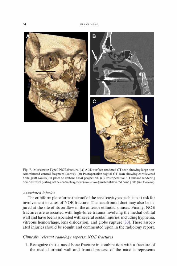
Fig. 7. Markowitz Type I NOE fracture. (A) A 3D surface-rendered CT scan showing large non-
comminuted central fragment (arrow). (B) Postoperative sagital CT scan showing cantilevered
bone graft (arrow) in place to restore nasal projection. (C) Postoperative 3D surface rendering
demonstratesplatingof the central fragment (thin arrow) and cantileveredbonegraft (thick arrow).
64 FRAIOLI et al
Associated injuries
The cribiformplate forms the roof of the nasal cavity; as such, it is at risk forinvolvement in cases of NOE fracture. The nasofrontal duct may also be in-jured at the site of its outflow in the anterior ethmoid sinuses. Finally, NOEfractures are associated with high-force trauma involving the medial orbitalwall and have been associatedwith several ocular injuries, including hyphema,vitreous hemorrhage, lens dislocation, and globe rupture [30]. These associ-ated injuries should be sought and commented upon in the radiology report.
Clinically relevant radiology reports: NOE fractures
1. Recognize that a nasal bone fracture in combination with a fracture ofthe medial orbital wall and frontal process of the maxilla represents

Fig. 8. NOE fracture and repair. (A) Axial CT through the NOE shows a left Type II (small
fracture fragment, but still attached to the canthal ligament) fracture (arrow). (B) Postoperative
frontal radiograph shows a cerclage wire (arrows) attached to both NOE fragments to hold
them into position.
65FACIAL FRACTURES
disruption of a facial unit known as the nasal-orbital-ethmoid (NOE)complex.
2. Indicate whether the central fragment of the medial orbital wall (towhich the medial canthal tendon attaches) is displaced and/orcomminuted.
3. Comment on the degree of displacement of the nasal root (nasal bridge),either posteriorly into the ethmoids or superiorly into the anterior cra-nial fossa.
4. Comment on the degree of comminution of the nasal bones, frontal pro-cesses of the maxilla, and nasal processes of the frontal bones, as commi-nution in these areas may require the surgeon to plan for bone grafting.
5. Comment on the presence or absence of commonly associated injuries,including cribiform plate fracture, nasofrontal duct injury, and ocularinjury.
Orbital wall and floor fractures
There are two main types of orbital fractures. The first type occurs whenone or more of the bony walls of the orbit are fractured. The inferior orbitalrim, in particular, is frequently fractured and displaced inward into theorbit. The displaced bone directly impacts the more delicate bones of theorbital walls and orbital floor, resulting in secondary fractures in theseregions. Because the inferior orbital rim is derived largely from the zygo-matic bone, fractures of the zygoma or its attachments that result in dis-placement of the zygoma frequently cause secondary fractures of theorbital walls and floor [38]. The second type of orbital fracture is what is

66 FRAIOLI et al
commonly known as an orbital ‘‘blowout’’ fracture. In this type of fracture,the orbital rim remains intact, but the force of impact is transmitted to thedelicate bones of the orbital floor, roof, and medial wall (Fig. 9), causingfractures in these bones without disrupting the continuity of the strongerinferior, lateral, and superior orbital rims.
Structures involved
The orbit is shaped like a cone, with the apex posteriorly. The greatestdiameter is not at the inferior orbital rim, however, but approximately 15mm posterior to it, at a point where the medial wall, roof, and floor ofthe orbit are all concave relative to each other [39]. Posterior and postero-medially to this, the orbital floor becomes convex. This configuration hasimportant implications for reconstruction of orbital fractures, as failure toreconstruct the convex portion (including the medial orbital wall) is oneof the common causes of postoperative enophthalmos [40].
Variables affecting treatment
The primary determination to make when assessing the CT scan iswhether the orbital fracture is an isolated blowout fracture or part of a largerfracture pattern. Orbital fractures occur in combination not only with ZMCfractures but also with Le Fort and NOE fractures. If the orbital fracturesconsist only of fractures of the orbital floor, roof, or medial wall withoutfracture of the firm orbital rims, then the treatment algorithm for orbitalblowout fractures applies. Orbital fractures occurring along with other frac-ture patterns are more likely to be the result of a high-force injury, and fre-quently require a more extensive surgical repair.
Fig. 9. Orbital blowout fractures. Although orbital floor fractures (arrow, A and B) are the
most common type of blowout fracture, medial wall fractures (arrowheads, A) and superior
wall fractures (arrow, B) may also be seen.

67FACIAL FRACTURES
There are three main indications to treat isolated orbital wall fractures.The first is entrapment of any of the extraocular muscles. Entrapment ofthe muscle can cause ischemic damage, and permanent dysfunction canoccur if the fracture is not reduced and the muscle released expeditiously[41,42]. Entrapment is diagnosed on clinical exam and cannot be directlyassessed on CT. However, herniation of the extraocular muscles beyondthe bony margins of the orbit is suggestive of entrapment and should besought on CT. The radiologic diagnosis of herniation may be especially dif-ficult in children, as the more pliable bone may result in ‘‘trapdoor’’ frac-tures (Fig. 10). These fractures result when the bone of the inferior orbitis displaced inferiorly and forms a greenstick fracture. The pliable bones
Fig. 10. Orbital ‘‘trapdoor’’ fracture. (A) The small mass of soft tissue at the maxillary sinus
roof could be confused with blood, but it actually represents a herniated and incarcerated right
inferior rectus muscle. Note the loss of the inferior rectus muscle shadow (compare with right
eye, arrowhead). (B) The fracture is subtle on bone windows because the displaced bone has
snapped back into place. (C) Postoperative coronal CT scan showing reduction of the fracture
with reappearance of the inferior rectus muscle shadow within the orbit.
68 FRAIOLI et al
then snap rapidly back into to a near-normal position, but the inferior rectusmuscle can become trapped in the fracture line in the process. This mayoccur without any evidence of bone loss in the orbital floor or blood orsoft tissue in the maxillary sinus. CT findings in trapdoor-type fracturescan be quite subtle, and may be overlooked if they are not actively sought[41]. One characteristic finding in such fractures is the loss of the inferior rec-tus muscle in the orbit (see Fig. 10). Coronal reformats are critical in theevaluation of the orbital floor.
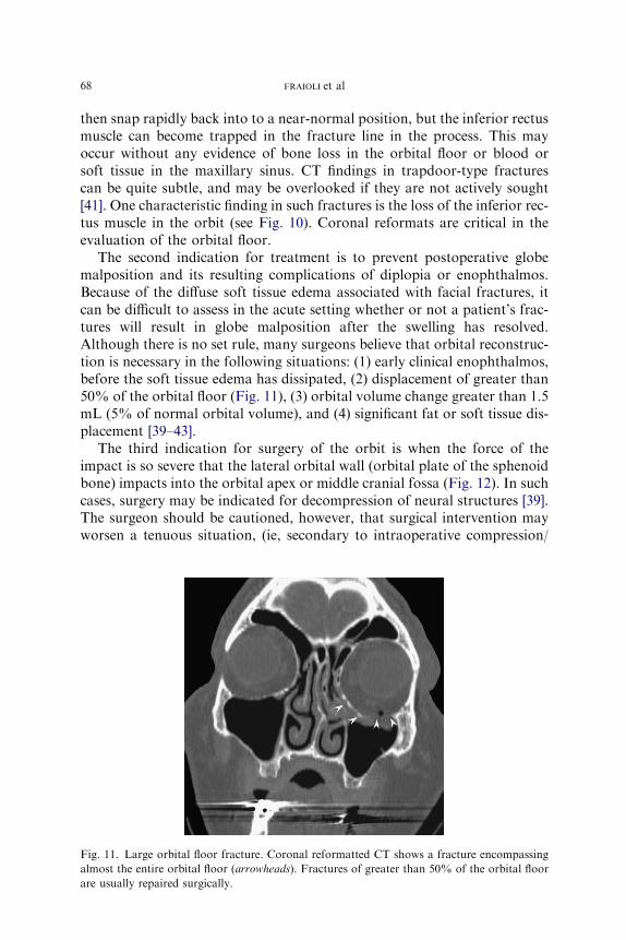
The second indication for treatment is to prevent postoperative globemalposition and its resulting complications of diplopia or enophthalmos.Because of the diffuse soft tissue edema associated with facial fractures, itcan be difficult to assess in the acute setting whether or not a patient’s frac-tures will result in globe malposition after the swelling has resolved.Although there is no set rule, many surgeons believe that orbital reconstruc-tion is necessary in the following situations: (1) early clinical enophthalmos,before the soft tissue edema has dissipated, (2) displacement of greater than50% of the orbital floor (Fig. 11), (3) orbital volume change greater than 1.5mL (5% of normal orbital volume), and (4) significant fat or soft tissue dis-placement [39–43].
The third indication for surgery of the orbit is when the force of theimpact is so severe that the lateral orbital wall (orbital plate of the sphenoidbone) impacts into the orbital apex or middle cranial fossa (Fig. 12). In suchcases, surgery may be indicated for decompression of neural structures [39].The surgeon should be cautioned, however, that surgical intervention mayworsen a tenuous situation, (ie, secondary to intraoperative compression/
Fig. 11. Large orbital floor fracture. Coronal reformatted CT shows a fracture encompassing
almost the entire orbital floor (arrowheads). Fractures of greater than 50% of the orbital floor
are usually repaired surgically.

Fig. 12. High-impact orbital fracture. The orbital floor fracture on this axial CT extends from
the inferior orbital rim (arrow) all the way to the apex (arrowhead), where it involves the lateral
wall of the optic canal. Extension to the rim or apex indicates high traumatic force, and is an
important factor in surgical repair.
69FACIAL FRACTURES
manipulation of the orbital apex), and preoperative consultation with anophthalmologist is recommended.
Clinically-relevant radiology reports: Orbital fractures
1. Note the presence or absence of extraocular muscle herniation. Muscleentrapment is a surgical emergency, so when herniation is identified onCT, the surgeon should be notified immediately.
2. Determine whether the orbital fracture is an isolated blowout fracture,or part of a larger fracture pattern (ZMC, NOE, Le Fort).
3. Identify which orbital walls are fractured: when one wall is fractured,look carefully at the other walls.
4. Estimate the size of each of the fractures (ie, in cm2 or in percentage offloor/walls) and the degree of displacement of fat and soft tissues.
Le Fort fractures
More than 100 years ago, Rene Le Fort devised a classification system formidface fractures. This classification scheme is based on his finding thatblunt trauma tends to cause fractures along three particular lines of weak-ness inherent in the design of the facial skeleton [38]. Le Fort based his sys-tem on his observation of experimental fractures made in cadavers.Fractures occurring in 21st-century, real-life situations (in particular,high-velocity motor vehicle accidents) often deviate from this classificationsystem, and ‘‘pure’’ Le Fort fractures are rare. Nevertheless, the Le Fort

70 FRAIOLI et al
classification system is widely known, and it provides a method for concisecommunication of fracture patterns between clinicians and radiologists.
Structures involved
There are three types of Le Fort fractures (Fig. 13). Each Le Fort leveldescribes not an isolated fracture, but rather a pattern of fractures involvingmultiple facial bones. The most consistent and uniting feature of the Le Fortfractures is the presence of bilateral pterygoid fractures. Pterygoid fracturesare found in all three classes of Le Fort fractures, and are the key to estab-lishing the diagnosis [44]. If a CT reveals bilateral pterygoid fractures, a LeFort fracture should be suspected. Conversely, if the CT scan does notreveal pterygoid fractures, the Le Fort fractures can be excluded [44].
The Le Fort I fracture is a horizontal fracture through the maxilla,cephalic to the maxillary dentition. Bones fractured in a Le Fort I patterninclude the lower nasal septum, the inferior portion of the piriform aper-tures, the canine fossae, both zygomaticomaxillary buttresses, the posteriormaxillary walls, and the pterygoid plates. The Le Fort II fracture is oftendescribed as being pyramidal in shape [44]. It traverses the nasofrontal junc-tion and extends laterally across the medial orbital wall, orbital floor,infraorbital rim, and then through the zygomaticomaxillary suture line. Italso proceeds posteriorly through the nasal septum and pterygoid plates.The Le Fort III fracture is a complete craniofacial separation, resulting inseparation of the facial bones from the cranium along the line of the naso-frontal and zygomaticofrontal suture lines. As in Le Fort II fractures, thefracture transverses the nasofrontal junction and extends laterally throughthe orbit; however, Le Fort III fractures involve not only the medial andinferior orbital walls but also the lateral orbital wall, zygomaticofrontalsuture line, and zygomatic arch. As with the other Le Fort fractures, thefracture line also extends posteriorly through the nasal septum and ptery-goid plates.
Each Le Fort fracture pattern has at least one unique component fracturethat is easily recognizable and separates it from the other Le Fort fractures[44]. Rhea and Novelline recently used these unique identifying fractures todesign a simple method for identifying and classifying facial fractures [44].Only the Le Fort I fracture involves the lateral aspect of the piriform aper-ature. Only the Le Fort II fracture involves the inferior orbital rim andzygomaticomaxillary suture line. Finally, only the Le Fort III fractureinvolves the zygomatic arch and the lateral orbital wall. When midfacialfractures are present and a Le Fort fracture pattern is suspected, the authorsrecommend first looking at the pterygoid plates. If there is a bilateral pter-ygoid fracture, a Le Fort fracture is likely present. The next step is to inspectthe three defining fractures discussed above: the lateral piriform aperatures,the inferior orbital rim, and the zygomatic arch. The presence or absence ofeach of these fractures determines whether a fracture of that type is present
71FACIAL FRACTURES
or absent [44]. For example, the absence of a lateral piriform fracture rulesout a Le Fort I; the presence of a zygomatic arch fracture makes is likelythat a Le Fort III fracture is present.
The final step is then to look systematically for fractures of the otherbones that are involved in the Le Fort levels. This is important because itis possible to have a Le Fort fracture on one side and an isolated ZMCor NOE fracture on the other side. The presence of the key indicator frac-tures does not definitively diagnose the Le Fort level; instead, it serves toalert the radiologist to the high likelihood of a particular Le Fort fracture.The other associated fractures must still be identified. Finally, it is possibleto have more than one Le Fort level on a single side of the facial skeleton[44]. For this reason, all three key indicator fractures must be examined,allowing each Le Fort level to be ruled in or ruled out, regardless of whetherthere is a coexisting Le Fort fracture of a different level [44].
Variables affecting treatment
Le Fort fractures result in both a cosmetic and a functional deficit. Asdiscussed above, the facial skeleton is formed by a combination of the rela-tively strong bones forming the midfacial buttresses, and the more fragilebones containing air-filled sinuses that lie deep to the buttresses (seeFig. 1). Le Fort fractures generally disrupt both. These fractures are causedby forces strong enough to break the buttresses, which then collapse inter-nally and result in the secondary fracture of the more fragile internal bones.The result, as with NOE fractures, is retrusion of the central midface. Inaddition, Le Fort fractures may result in a loss of the vertical height ofthe face as a result of interruption of the vertical buttresses. Finally, theforce required to cause a Le Fort fracture generally results in other facialbone fractures, and these add to the difficulty of the surgical repair.
Fractures of the hard palate or dentoalveolar units are frequently associ-ated with Le Fort fractures (Fig. 14). The presence of such fractures is clin-ically important, as they further disrupt the patient’s occlusion, addingsignificantly to the complexity of fracture repair. To achieve normal midfaceprojection, normal occlusion must be restored before anchoring the uppermidface to the maxilla. Similarly, the presence of a coexisting mandibularfracture will affect the occlusion. For Le Fort II and III fractures, associatedZMC, NOE, or frontal sinus fractures must be recognized. The frontal barmust be reconstructed before the midface can be resuspended to it.
The goals of treatment are thus to restore occlusion, facial height, andfacial projection. Knowledge of the Le Fort levels involved on each side iscrucial when making the operative plan, as the surgical access incisiondepends greatly on the level of fracture. Le Fort Level I fractures may beaccessed via a gingivo-buccal sulcus incision, whereas Le Fort II and III frac-tures may require a coronal and possibly an orbital access incision such as thetransconjunctival or subcillary approach [45]. The final consideration is the
72 FRAIOLI et al

Fig. 14. Axial CT scan demonstrating oblique palatal fracture (arrows) in a patient with bilat-
eral Le Fort fractures. The presence of associated palatal fracture adds to the difficulty of estab-
lishing dental occlusion before fracture reduction.
73FACIAL FRACTURES
degree of comminution of the involved bones. The buttresses must be recre-ated to restore facial height and projection. If the buttresses are severely com-minuted, they may be inadequate for this function, and bone grafting may benecessary.
A final consideration, as with other high-energy fractures, is the orbitalapex. Many Le Fort fractures extend to the anterior cranial base, and indoing so the fracture lines traverse the orbital apex. Although not describedby Le Fort, some authors refer to this type of fracture as a ‘‘Le Fort IV’’fracture [29,45]. Le Fort fractures are frequently reduced with disimpactionforceps and a great deal of manual force. Fracture lines through the orbitalapex and close to the carotid canal must be identified on preoperative CTscan to alert the surgeon to use a more gentle reduction technique to avoiddisrupting the fractured bones in these critical areas [29].
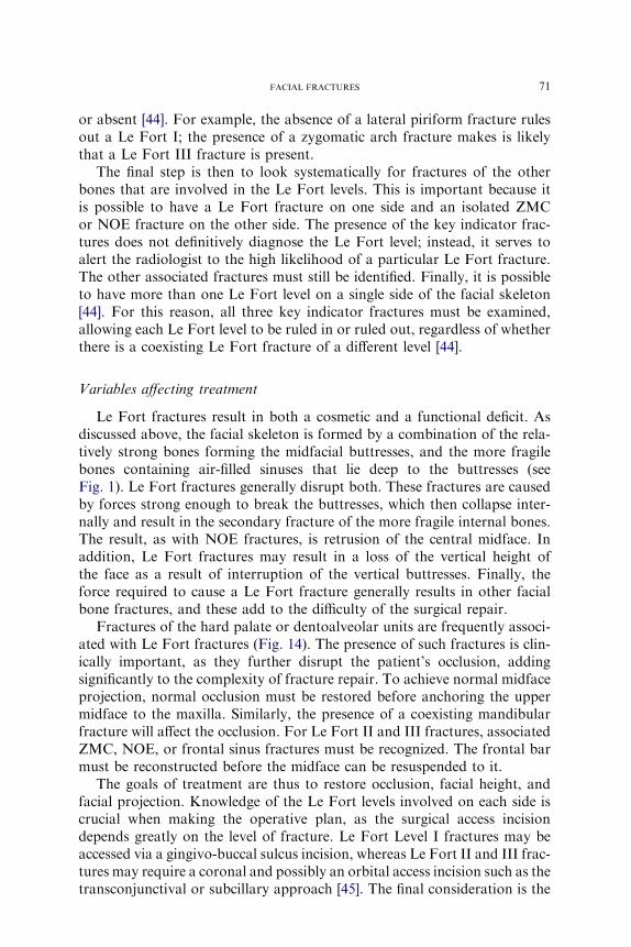
Fig. 13. Le Fort fractures. (A) Schematic of the Le Fort fracture patterns. (From Linnau KF,
Stanley RB Jr, Hallam DK, et al. Imaging of high-energy midfacial trauma: what the surgeon
needs to know. Eur J Radiol 2003;48:17–32; with permission.) (B) Axial CT scan demonstrating
fractures of the bilateral pterygoid plates (arrows). Presence of bilateral pterygoid plate frac-
tures is strongly suggestive of the presence of Le Fort fractures. (C) Coronal reformat of
a Le Fort I fracture shows fracture lines extending though the walls of the maxillary antrum
(arrows) and across the nasal septum, without orbital involvement. (D) Coronal reformat of
a LeFort II fracture shows fracture lines through the maxillary antrum (arrow), and through
the inferior and medial walls of the orbital (arrowheads), as well as the nasal bridge. (E) Coronal
reformat of a Le Fort III fracture shows fractures though the zygomatic arch and lateral orbital
walls (arrow), as well as the orbital roofs (arrowhead).
;

74 FRAIOLI et al
Clinically relevant radiology reports: Le Fort fractures
1. Indicate which Le Fort levels are involved. Le Fort levels may differbetween the two sides of the face, and fractures may occur throughmore than one Le Fort level on the same side of the face.
2. Other facial fracture patterns such as NOE, frontal sinus, and ZMCfractures frequently occur in association with Le Fort fracture patterns,and should be noted.
3. Fractures of the hard palate, maxillary dentoalveolar units, and mandi-ble will affect occlusion and thus affect the repair; these injuries shouldbe specifically sought.
References
[1] Bell RB, Dierks EJ, Brar P, et al. A protocol for the management of frontal sinus fractures
emphasizing sinus preservation. J Oral Maxillofac Surg 2007;65(5):825–39.
[2] Strong E, Sykes J. Frontal sinus and nasoorbitoethmoid complex fractures. In: Papel I,
editor. Facial plastic and reconstructive surgery. 2nd edition. New York: Thieme; 2002.
p. 747–58.
[3] Metzinger SE, Guerra AB, Garcia RE. Frontal sinus fractures: management guidelines.
Facial Plast Surg 2005;21(3):199–206.
[4] Wilson BC, Davidson B, Corey JP, et al. Comparison of complications following frontal
sinus fractures managed with exploration with or without obliteration over 10 years. Laryn-
goscope 1988;98(5):516–20.
[5] Tan L, Bailey B. Fractures of the frontal sinus. In: Bailey B, Johnson J, Newlands S, editors.
Head&neck surgerydotolaryngology. vol. 1. 4th edition. Philadelphia: LippincottWilliams
& Wilkins; 2006. p. 1009–15.
[6] Wallis A, Donald PJ. Frontal sinus fractures: a review of 72 cases. Laryngoscope 1988;98
(6 Pt 1):593–8.
[7] Strong EB, Pahlavan N, Saito D. Frontal sinus fractures: a 28-year retrospective review.
Otolaryngol Head Neck Surg 2006;135(5):774–9.
[8] Chen KT, Chen CT, Mardini S, et al. Frontal sinus fractures: a treatment algorithm and
assessment of outcomes based on 78 clinical cases. Plast Reconstr Surg 2006;118(2):
457–68.
[9] Lawson W. Frontal sinus. In: Blitzer A, Lawson W, Friedman W, editors. Surgery of the
paranasal sinuses. 2nd edition. Philadelphia: W.B. Saunders Company; 1991. p. 183–218.
[10] GerbinoG,RocciaF, BenechA, et al. Analysis of 158 frontal sinus fractures: current surgical
management and complications. J Craniomaxillofac Surg 2000;28(3):133–9.
[11] GossmanDG,Archer SM, ArosarenaO.Management of frontal sinus fractures: a review of
96 cases. Laryngoscope 2006;116(8):1357–62.
[12] Luce EA. Frontal sinus fractures: guidelines to management. Plast Reconstr Surg 1987;
80(4):500–10.
[13] Linnau KF, Stanley RB Jr, Hallam DK, et al. Imaging of high-energy midfacial trauma:
what the surgeon needs to know. Eur J Radiol 2003;48(1):17–32.
[14] Stanley RB. Management of frontal sinus fractures: a review of 33 cases. J Oral Maxillofac
Surg 1999;57(4):380–1.
[15] Donald PJ, EttinM. The safety of frontal sinus fat obliteration when sinus walls are missing.
Laryngoscope 1986;96(2):190–3.
[16] Stanley RB Jr, Becker TS. Injuries of the nasofrontal orifices in frontal sinus fractures-
Laryngoscope 1987;97(6):728–31.

75FACIAL FRACTURES
[17] Wormald PJ. Salvage frontal sinus surgery: the endoscopic modified Lothrop procedure-
Laryngoscope 2003;113(2):276–83.
[18] Wormald PJ, Ananda A, Nair S. Modified endoscopic lothrop as a salvage for the failed
osteoplastic flap with obliteration. Laryngoscope 2003;113(11):1988–92.
[19] Smith TL, Han JK, Loehrl TA, et al. Endoscopic management of the frontal recess in frontal
sinus fractures: a shift in the paradigm? Laryngoscope 2002;112(5):784–90.
[20] Manson PN,Markowitz B,Mirvis S, et al. TowardCT-based facial fracture treatment. Plast
Reconstr Surg 1990;85(2):202–12 [discussion: 213–4].
[21] Koch R, HanasonoM. Aesthetic facial analysis. In: Papel I, editor. Facial plastic and recon-
structive surgery. 2nd edition. New York: Thieme; 2002. p. 135–44.
[22] Gruss JS, VanWyck L, Phillips JH, et al. The importance of the zygomatic arch in complex
midfacial fracture repair and correction of posttraumatic orbitozygomatic deformities. Plast
Reconstr Surg 1990;85(6):878–90.
[23] Stanley RB Jr. The zygomatic arch as a guide to reconstruction of comminuted malar
fractures. Arch Otolaryngol Head Neck Surg 1989;115(12):1459–62.
[24] Ellis E 3rd, Kittidumkerng W. Analysis of treatment for isolated zygomaticomaxillary
complex fractures. J Oral Maxillofac Surg 1996;54(4):386–400 [discussion: 400–1].
[25] Bite U, Jackson IT, Forbes GS, et al. Orbital volume measurements in enophthalmos using
three-dimensional CT imaging. Plast Reconstr Surg 1985;75(4):502–8.
[26] Shumrick KA, Kersten RC, Kulwin DR, et al. Criteria for selective management of the
orbital rim and floor in zygomatic complex and midface fractures. Arch Otolaryngol
Head Neck Surg 1997;123(4):378–84.
[27] Covington DS, Wainwright DJ, Teichgraeber JF, et al. Changing patterns in the epidemiol-
ogy and treatment of zygoma fractures: 10-year review. J Trauma 1994;37(2):243–8.
[28] Ellis E 3rd, Reddy L. Status of the internal orbit after reduction of zygomaticomaxillary
complex fractures. J Oral Maxillofac Surg 2004;62(3):275–83.
[29] Linnau KF, Hallam DK, Lomoschitz FM, et al. Orbital apex injury: trauma at the junction
between the face and the cranium. Eur J Radiol 2003;48(1):5–16.
[30] Shelton D. Nasal-Orbital-Ethmoid fractures. In: Alling CI, Osbon D, editors. Maxillofacial
trauma. Philadelphia: Lea & Febiger; 1988. p. 363–71.
[31] Hollinshead W. Anatomy for surgeon volume 1: the head and neck. 3rd edition. Philadel-
phia: Harper & Row; 1982.
[32] Leipziger LS, Manson PN. Nasoethmoid orbital fractures. Current concepts and manage-
ment principles. Clin Plast Surg 1992;19(1):167–93.
[33] Holt GR, Holt JE. Nasoethmoid complex injuries. Otolaryngol Clin North Am 1985;18(1):
87–98.
[34] Gruss JS. Fronto-naso-orbital trauma. Clin Plast Surg 1982;9(4):577–89.
[35] Becelli R, Renzi G, Mannino G, et al. Posttraumatic obstruction of lacrimal pathways:
a retrospective analysis of 58 consecutive naso-orbitoethmoid fractures. J Craniofac Surg
2004;15(1):29–33.
[36] Markowitz BL, Manson PN, Sargent L, et al. Management of the medial canthal tendon in
nasoethmoid orbital fractures: the importance of the central fragment in classification and
treatment. Plast Reconstr Surg 1991;87(5):843–53.
[37] Herford AS, Ying T, Brown B. Outcomes of severely comminuted (type III) nasoorbitoeth-
moid fractures. J Oral Maxillofac Surg 2005;63(9):1266–77.
[38] Stack BC, Ruggiero FP. Maxillary and periorbtial fractures. In: Bailey BJ, Johnson JT,
Newlands S, editors. Head & neck surgerydotolaryngology. vol. 1. 4th edition. Philadel-
phia: Lippincott Williams, Wilkins; 2006. p. 975–93.
[39] Stanley R.Maxillofacial trauma. In: Cummings CW, editor. Otolaryngology head and neck
surgery. vol. 1. 3rd edition. St. Louis (MO): CV Mosby; 1996. p. 453–85.
[40] Stanley R. Treatment of orbitozygomatic fractures. In: Papel I, editor. Facial plastic
and reconstructive surgery. 2nd edition. New York: Thieme Medical Publishing; 2002.
p. 738–46.

76 FRAIOLI et al
[41] Bansagi ZC, Meyer DR. Internal orbital fractures in the pediatric age group: characteriza-
tion and management. Ophthalmology 2000;107(5):829–36.
[42] Chang EW, Manolidis S. Orbital floor fracture management. Facial Plast Surg 2005;21(3):
207–13.
[43] Hartstein ME, Roper-Hall G. Update on orbital floor fractures: indications and timing for
repair. Facial Plast Surg 2000;16(2):95–106.
[44] Rhea JT, Novelline RA. How to simplify the CT diagnosis of Le Fort fractures. AJR Am J
Roentgenol 2005;184(5):1700–5.
[45] Manson PN. Management of midfacial fractures. In: Georgiade G, Georgiade N, Riefkohl
R, editors. Textbook of plastic, maxillofacial and reconstructive surgery, vol. I. 2nd edition.
Baltimore (MD): Williams & Wilkins; 1992. p. 409–32.