fabrication of nanostructures by roll-to-roll extrusion ... · as roll-to-roll extrusion coating...
TRANSCRIPT

General rights Copyright and moral rights for the publications made accessible in the public portal are retained by the authors and/or other copyright owners and it is a condition of accessing publications that users recognise and abide by the legal requirements associated with these rights.
• Users may download and print one copy of any publication from the public portal for the purpose of private study or research. • You may not further distribute the material or use it for any profit-making activity or commercial gain • You may freely distribute the URL identifying the publication in the public portal
If you believe that this document breaches copyright please contact us providing details, and we will remove access to the work immediately and investigate your claim.
Downloaded from orbit.dtu.dk on: Dec 21, 2017
Fabrication of Nanostructures by Roll-to-Roll Extrusion Coating
Murthy, Swathi; Matschuk, Maria; Huang, Qian; Mandsberg, N.K.; Feidenhans'l, Nikolaj Agentoft;Johansen, P.; Christensen, L.; Pranov, H.; Kofod, G.; Pedersen, Henrik Chresten; Hassager, Ole;Taboryski, Rafael J.Published in:Advanced Engineering Materials
Link to article, DOI:10.1002/adem.201500347
Publication date:2015
Document VersionPeer reviewed version
Link back to DTU Orbit
Citation (APA):Murthy, S., Matschuk, M., Huang, Q., Mandsberg, N. K., Feidenhans'l, N. A., Johansen, P., ... Taboryski, R. J.(2015). Fabrication of Nanostructures by Roll-to-Roll Extrusion Coating. Advanced Engineering Materials, 18(4),484-489. DOI: 10.1002/adem.201500347

1
DOI: 10.1002/((please add manuscript number))
Article type: Communication
Fabrication of nanostructures by roll-to-roll extrusion coating
Swathi Murthy, Maria Matschuk, Qian Huang, Nikolaj K. Mandsberg, Nikolaj A.
Feidenhans’l, Peter Johansen, Lars Christensen, Henrik Pranov, Guggi Kofod, Henrik C.
Pedersen, Ole Hassager, Rafael Taboryski*
Ms. S. Murthy, Dr. M. Matschuk, Dr. H. Pranov, Dr. G. Kofod
Inmold A/S, Diplomvej 381, DK-2800 Kongens Lyngby, Denmark
Ms. S. Murthy, Prof. Henrik C. Pedersen
Department of Photonics Engineering, Technical University of Denmark, Frederiksborgvej
399, DK-4000 Roskilde, Denmark
Dr. Q. Huang, Prof. O. Hassager
Department of Chemical and Biochemical Engineering, Technical University of Denmark,
Søltofts Plads, building 229, DK-2800 Kongens Lyngby, Denmark
Mr. N. A. Feidenhans’l
Danish Fundamental Metrology A/S, Matematiktorvet 307, Kgs. Lyngby, Denmark
Mr. N. Mandsberg, Mr. Nikolaj A. Feidenhans’l, Prof. R.Taboryski
Department of Micro- and Nanotechnology, Technical University of Denmark, Ørsteds Plads,
building 345b, DK-2800, Kongens Lyngby, Denmark
E-mail: [email protected]
Mr. Peter Johansen, Mr. Lars Christensen, Danapak Flexibles A/S, Strudsbergsvej 3, DK-
4200 Slagelse, Denmark
The drivers in the development of large area micro- and nanostructuring roll-to-roll (R2R)
methods have been hologram security stickers, flexible electronics, graphene electrodes, and
organic solar cells.[1]
In terms of productivity for large area nanostructuring, the most
established technology is roll-to-roll UV assisted nanoimprint lithography (R2R-UV-NIL), as
demonstrated by Ahn et al, who reported replication of 300 nm line gratings using UV-
curable imprint resist at a line-speed of 1 m/min.[2, 3]
This method is limited in the choice of
materials by the requirement of photo-curability. The throughput for current R2R-UV-NIL
systems amounts to 0.2 m2/s. Another widely used technology is R2R hot embossing (R2R-
2
HE), in which a heated structured roller is used to emboss a structure into a thin film in a R2R
process.[4, 5]
The full potential of extending R2R techniques to nanostructuring of biomimetic
functionalities such as super-hydrophobic[6]
, anti-reflective [7]
, structural and plasmonic color
effects[8]
, is however today impeded by the relatively low throughput of R2R-UV-NIL and
R2R-HE.[4, 9]
These limitations seem associated with the rheology of polymer flow and the
rate of UV-curing processes.[3]
This paper investigates a novel R2R process for nano- and microstructuring, potentially
having improved productivity with rates exceeding 5 m2/s (Figure 1). The process is known
as roll-to-roll extrusion coating (R2R-EC, in the packaging industry commonly referred to as
co-extrusion), which is widely used for production of smooth polymer films. Among benefits
of R2R-EC are availability of a wide range of commercial extruders, off-the-shelf extrusion
grade polymers, functional additives, polymeric materials with good diffusion barrier
properties, and the overall maturity of the technology. However, only few studies have been
devoted to this process. Frenkel et al.[10]
reported replication by R2R-EC of sawtooth
microstructures with line-speed 10 m/min, while Sollogoub et al.[11]
described the rheological
processes associated with standard R2R-EC. To our knowledge, there is no work describing
production of nanostructured polymer films by R2R-EC so far.
In R2R-EC a molten polymer film (melt curtain) is extruded through a flat nozzle, then
stretched in air, and finally laminated onto a carrier foil (substrate). The lamination process
takes place as the melt curtain is squeezed between a structured cooling roller and a rubber
counter roller. A force is exerted on the compliant counter roller to form a so-called nip region
where the molten polymer solidifies and adheres to the carrier foil as shown in Figure 1a.
Compared to R2R-UV-NIL and R2R-HE, the extrusion coating process is much faster, mainly
due to the fact that the polymer is molten to begin with, and cools rapidly by contact with the
cooling roller. When compared to other R2R techniques, R2R-EC resembles R2R-HE, in
respect to pressure ranges, but is much less affected by the slow creep-strain effects
3
encounered in R2R-HE.[4]
R2R-EC can also be compared to the polymer injection molding
(IM) process.[12]
In IM, the polymer is also molten at the onset of relief filling. Important
differences between R2R-EC and IM are however the pressure and rheological conditions
during relief filling. The nip pressure in R2R-EC is low (20 bar), while injection pressures
for IM typically reach much higher values (1000 bar). In addition, for IM, the shear stress
typically exceeds the critical value for wall slip, [13]
whereas this is not the case in R2R-EC,
where the shear rate in the nip is practically zero.[11]
Most extruders have multi-feed nozzles,
allowing for e.g. an adhesion layer to be co-extruded with the structure layer for better
adhesion to the carrier foil. If a relief structure is attached to the surface of the cooling roller,
the pressure buildup in the nip will force intrusion of the molten polymer into the relief
structure, which is the topic of investigation in this paper. R2R-EC is simpler than R2R-UV-
NIL, as it does not require any curing step.
We demonstrate large area replication at high throughput of patterns both on micrometer-
(Figure 1b, c) and nanometer scale (Figure 2) in thermoplastic foils using standard industrial
R2R-EC equipment and standard thermoplastic polymers. We argue that different regimes of
replication exist; a nanostructure regime, where replication is dominated by surface tension of
the melt in the nip, and a microstructure regime where microscopic flow is required to fill the
deeper microstructures. Nanostructures with typical linewidth in the range 100 - 400 nm are
best replicated using semi-crystalline polymers such as polypropylene (PP), running at high
roller line-speed 𝑉𝑅, and high cooling roller temperature 𝑇𝑐 (Figure 2). The best replication of
nanopillars (diameter: 120 nm and height: 100 nm in Si master) was obtained for 𝑇𝐶 = 70 C
and the highest line-speed 𝑉𝑅 = 60 m/min (Figure 2a,b), whereas e.g. at 𝑇𝐶 = 30 C and
𝑉𝑅 = 10 m/min, the pillars were only 50% replicated in terms of height compared to the Si
master (Figure 2c,d,e). For the used parameter range, this degree of replication at nanoscale
was only achieved in PP. Replication in other common polymers like polyethylene (PE) and

4
polystyrene (PS) was not possible for nanostructures.[14]
Structures with linewidths and depths
above ca. 400 nm seem to belong to a different replication regime allowing for a wider range
of materials.[14]
For microstructures (see Figure 1c), we find that process parameters
(𝑉𝑅 , 𝐹, 𝑇𝐶) have to be individually optimized for each pattern, indicating that viscoelastic flow
into the relief plays a more important role.[4]
We believe this difference originates from the
thermo-mechanical conditions in the nip as shown in Figure 3. Both nano- and
microstructures require a pressure buildup in the nip for good replication. This is achieved by
the compliance of the rubber counter roller. We adapted the theory for contact between two
deformable solids to predict the pressure profile in the nip.[11, 15]
A force 𝐹 is applied to the
counter roller resulting in a pressure within the nip,
𝑃𝑛𝑖𝑝 = 𝑃𝑚𝑎𝑥√1 − (𝐿𝑛𝑖𝑝 − 2𝑥
𝐿𝑛𝑖𝑝)
2
, (1)
where 𝑃𝑚𝑎𝑥 = 𝐹/(𝜋𝑊𝐿𝑛𝑖𝑝), 𝑥 is the distance along the nip from the entrance, 𝐿𝑛𝑖𝑝 is the
length of the nip region (see Figure 1a), and 𝑊 is the width of the rollers. The calculated
pressure curves in the nip for three different force values are shown in Figure 3b. According
to Equation 1, the maximum pressure is reached at the center of the nip. The carrier foil and
the polymer passage in the nip do not significantly affect the pressure in the nip.
We modelled the temperature profile along the nip in a 100 µm thick polymer melt
sandwiched between the Ni mold and the polyethylene terephthalate (PET) carrier foil.[14]
The
model simulates the temperature variation at different distances from the mold surface in the
polymer along the nip. Our primary interest for this investigation is the cooling rate in the
polymer melt near the mold-polymer interface. The model shows that the polymer melt cools
very rapidly near the mold surface. In fact it cools even before entering the nip. The cooling
rate is of the order of 107 K /s at a distance 100 nm from the mold once it enters the nip, while
it cools much slower in the bulk of the polymer melt away from the mold surface (Figure 3c).
5
The high rate is due to the high thermal conductivity of Ni as compared to polymer. The line-
speed is an important factor affecting the temperature profile in the nip (Figure 3). At higher
line-speed the polymer solidifies further into the nip and the polymer melt experiences higher
nip pressure before solidification of the surface region (Figure 3).
The low pressure and the absence of shear stress in the nip indicate that no-slip boundary
conditions are expected to hold for nanopattern filling in the mold.[13, 16]
For a pressure ∆𝑃
across the melt/air interface, the radius of curvature 𝑅 is given by the Young-Laplace formula:
𝑅 =−2γ(𝑇) cos 𝜃𝑎
∆𝑃, (2)
where 𝛾(𝑇) is the temperature-dependent surface tension, while 𝜃𝑎 is the advancing contact
angle for the polymer melt intruding into the mold relief. As the antistiction coating[14, 17]
of
the roller ensures 𝜃𝑎~ 120, and hence cos 𝜃𝑎 ∼ -1/2, we argue that feature sizes smaller than
𝑅 ∼ 𝛾(𝑇) ∆𝑃⁄ cannot be replicated. The surface tension for polymer melts is known to
decrease linearly with temperature: [16, 18]
𝛾(𝑇) = 𝛾0 − 𝛼𝑇. (3)
For PP we used 𝛾0 = 27.734 mN/m and 𝛼 = 0.059 mN/(m C) reported by Duo Yang
et.al..[16]
The crystallization temperature obtained by differential scanning calorimetry (DSC)
in this work is 120 C at a cooling rate of 10 K/min. However, PP is a semi-crystalline
polymer, and we expect considerable crystallization retardation for the extremely high cooling
rate (107 K/s) near the mold.
[19] The polymer melt is thus expected to be supercooled and
solidify at much lower temperature 𝑇 ≳ 𝑇𝐶 = 70 C. If we conservatively assume
solidification at the temperature 120 C, we can follow the 60 m/min curve (100 nm from the
mold surface) in Figure 3d to arrive at a distance of 1 µm inside the nip for 𝑇 = 120 C. At
this distance, the nip pressure is 0.3 bar. The characteristic radius of curvature R for the PP
melt under 0.3 bar and 120 C is 650 nm calculated from Equation 2 and 3. In order to

6
completely fill the nanoholes in the mold, including the corners, 𝑅 should be smaller than the
radius of the nanoholes, i.e. 𝑅 ≲ 60 nm for 120 nm pillars (Figure 2). Since smaller pillars
were actually replicated at these conditions, this clearly indicates that supercooling of the
polymer melt must play an important role in the process. To confirm this hypothesis, we tried
to replicate nanopatterns using other polymers, polystyrene (PS) and polyethylene (PE). For
PS the glass transition temperature (𝑇𝑔) is 100 C, while the solidification temperature for
PE is 110 C. PS is an amorphous polymer; it solidifies below 𝑇𝑔 and cannot be supercooled.
Indeed, for the parameter range used in this investigation, it was not possible to achieve a
visible replication of structures in PS. Though PE is a semi-crystalline polymer and can be
supercooled, its crystallization rate is extremely high (compared to PP), which means that PE
solidifies quickly below its static solidification temperature (110 C).[20]
Hence, 𝑅 does not
become small enough to fill the nanoholes in the mold for PS and PE. From Figure 2, we see
that the cooling rate of the PP melt near the mold is 107 K/s at 𝑉𝑅 = 60 m/min. We cannot
measure the crystallization rate of PP at such high cooling rate as the maximum cooling rate
that presently can be attained by flash DSC is 104 K/s.
[21] However, the half crystallization
time for PP at 80 C is reported to vary from 0.2 to 10 seconds.[21, 22]
The polymer takes about
9 ms to reach the center of the nip (9 mm at 60 m/min), where the pressure is maximum and
hence 𝑅 is minimum. Since we observe complete replication of nanopillars at 60 m/min, it
indicates retardation of solidification of PP by a sufficient amount of time to attain a small
enough 𝑅. This explains why the replication of nanopillars (Figure 2) diminishes at lower 𝑉𝑅
and lower 𝑇𝑐. We observed incomplete replication of 40 nm structures and take this as the
lower limit for replication in the model.
In conclusion, we have demonstrated replication of micro- and nanostructures in
thermoplastic polymers, by a very high throughput, industrial process R2R-EC. Structures of
different dimensions, shapes and aspect ratios have been replicated with high replication

7
fidelity, and productivity up to 0.45 m2/s. Nanostructures down to 80 nm and height 100 nm
could be replicated in PP at 𝑉𝑅 = 60 m/min. The limiting factors for proper replication of
nanostructures were found to be the surface tension induced radius of curvature of the
polymer melt and the retardation time for crystallization of the melt. The retardation time
limitation leads to the surprising feature of the process, that the replication quality of
nanostructures in crystalline polymers becomes better the higher line-speed is used.
We suggest that the discovery of accurate and high productivity nano- and microscopic
replication in thermoplastic materials could accelerate the integration of nanostructured
materials in a broad range of applications, including optical, technical and functional surfaces
and devices. Further possible applications may include cast molding of advanced materials for
photo-voltaic, thermo-electric, electro-active and electro-storage applications, where
nanostructuring often leads to improved properties.
Experimental section
The nano-microstructured foils were produced by extrusion coating on a pilot roll-to-roll
extrusion coating machine, at Danapak Flexibles, Slagelse, Denmark. It consists of a 25 mm
extruder (BfA Plastic GmbH), 35 mm extruder (AXON Plastics Machinery AB), and an
EPOCH nozzle with a respective 3-layer feedblock (Cloeren Inc). Micro-nanostructured Ni
molds where fabricated by a dry etching, electroplating and molding (DEEMO) process.[14, 23]
The Ni molds were simply glued to the cooling roller (width 𝑊 = 45 cm, diameter 𝐷𝑐𝑜𝑜𝑙 =
27.2 cm) with double sided adhesive tape. The cooling roller is cooled by water, and its
temperature 𝑇𝑐 was kept below the solidification temperature of the polymer. The counter
roller (diameter 𝐷𝑐𝑜𝑢𝑛𝑡𝑒𝑟 = 12.5 cm) consisted of a metal core wrapped with a 10 mm thick
layer of silicone rubber, making it flexible on the surface. The counter roller was maintained
at room temperature using cooling water. The force 𝐹 applied across the nip was provided by

8
two hydraulic pistons, one attached at each end. The nip length 𝐿𝑛𝑖𝑝 was measured by
running a deformable tape through the nip at different applied force 𝐹 and measuring the
length of the deformation in the tape. The force across the nip is exerted by two hydraulic
pistons attached to the counter roller. 𝐹 is calculated by multiplying the measured oil pressure
𝑃𝑜𝑖𝑙 in the pistons with the surface area of the pistons. The rollers are not motorized; their
drive is supplied by the substrate drawn by the winder, creating a line tension, and resulting in
a line-speed 𝑉𝑅. PP was co-extruded with a polyethylene (PE) adhesion layer material at 295°
C and laminated onto a polyethylene terephthalate (PET) carrier foil.
The solidification temperature was measured by differential scanning calorimetry (DSC)
(DSC-Q1000, TA Instruments)(Figure S7).[14]
We investigated the nano-microreplication ability of various polymers, like pure PP
(WF420HMS, Borealis), low density polyethylene (LDPE ‐ 3020D, LyondellBasell),
polyethylene modified polypropylene (hereafter referred to as polyolefin, PO),
polymethylpentene, polystyrene (PS: BASF PS 158K) and cyclic olefin copolymer (Topas
8007X4, Topas Advanced Polymers GmbH).[14]
Different sets of processing parameters were
investigated to assess their influence on the replication fidelity.[14]
Specifically, the influence
of cooling roller temperature 𝑇𝑐 (30 C to 70 C), Line-speed 𝑉𝑅 (10 m/min to 60 m/min) and
nip force 𝐹 (7 to 30 kN/m) were explored separately, while keeping all other parameters
constant.[14]
For the parametric analysis, extruder output, melt temperature, feed rate, die-gap,
and air-gap height were kept constant. For each set of process parameters, several hundred
meters of polymer foil were produced. The replication was assessed and compared for
samples across different parameter sets. Several samples were cut from the same foils to
assess the homogeneity of replication. The structures shown in this paper were characterized
either by scanning electron microscopy (SEM - Zeiss Supra) or by atomic force microscopy

9
(AFM - Park Systems Corporation XE-150). Prior to SEM, the polymer foils were coated
with a 10 nm thin film of gold-palladium.
Supporting Information Supporting Information is available from the Wiley Online Library or from the author.

10
Acknowledgements
This work is supported by the Danish National Advanced Technology Foundation (HTF)
through the “Advanced Technology Project LANI” (grant 011-2011-3), the “Advanced
Technology Platform NanoPlast” (grant 007-2010-2), and by The Danish Ministry of Higher
Education and Science, through an industrial PhD scholarship for Swathi Murthy (grant 1355-
00143). Mr. Nis K. Andersen, Mr. Freddy Lang, and Ms. Nanna Bild are acknowledged for
help with the artwork.
Swathi Murthy and Maria Matschuk contributed equally to this work.
Received: ((will be filled in by the editorial staff))
Revised: ((will be filled in by the editorial staff))
Published online: ((will be filled in by the editorial staff))
References
[1] K. J. Baeg, M. Caironi, Y. Y. Noh, Advanced Materials 2013, 25, 4210; S. Bae, H.
Kim, Y. Lee, X. F. Xu, J. S. Park, Y. Zheng, J. Balakrishnan, T. Lei, H. R. Kim, Y. I. Song, Y.
J. Kim, K. S. Kim, B. Ozyilmaz, J. H. Ahn, B. H. Hong, S. Iijima, Nature Nanotechnology
2010, 5, 574; F. C. Krebs, J. Fyenbo, M. Jorgensen, Journal of Materials Chemistry 2010, 20,
8994; S. R. Forrest, Nature 2004, 428, 911.
[2] S. H. Ahn, L. J. Guo, Advanced Materials 2008, 20, 2044; S. Ahn, M.
Ganapathisubramanian, M. Miller, J. Yang, J. Choi, F. Xu, D. J. Resnick, S. V. Sreenivasan,
"Roll-to-Roll Nanopatterning Using Jet and Flash Imprint Lithography", presented at
Conference on Alternative Lithographic Technologies IV, San Jose, CA, 2012
Feb 13-16, 2012; C. Stuart, Y. Chen, Acs Nano 2009, 3, 2062; J. John, Y. Tang, J. P.
Rothstein, J. J. Watkins, K. R. Carter, Nanotechnology 2013, 24.
[3] S. H. Ahn, L. J. Guo, Acs Nano 2009, 3, 2304.
[4] Y. Deng, P. Yi, L. Peng, X. Lai, Z. Lin, Journal of Micromechanics and
Microengineering 2015, 25.
[5] M. D. Fagan, B. H. Kim, D. Yao, Advances in Polymer Technology 2009, 28, 246.
[6] K. Koch, B. Bhushan, Y. C. Jung, W. Barthlott, Soft Matter 2009, 5, 1386; E. Sogaard,
N. K. Andersen, K. Smistrup, S. T. Larsen, L. Sun, R. Taboryski, Langmuir 2014, 30, 12960.
[7] A. B. Christiansen, J. Clausen, N. A. Mortensen, A. Kristensen, Applied Physics
Letters 2012, 101.
[8] J. Clausen, A. B. Christiansen, J. Garnaes, N. A. Mortensen, A. Kristensen, Optics
Express 2012, 20, 4376; K. Kumar, H. G. Duan, R. S. Hegde, S. C. W. Koh, J. N. Wei, J. K.
W. Yang, Nature Nanotechnology 2012, 7, 557; J. S. Clausen, E. Hojlund-Nielsen, A. B.
Christiansen, S. Yazdi, M. Grajower, H. Taha, U. Levy, A. Kristensen, N. A. Mortensen,
Nano Letters 2014, 14, 4499.
[9] H. Tan, A. Gilbertson, S. Y. Chou, Journal of Vacuum Science & Technology B 1998,
16, 3926.
[10] R. Frenkel, B. Kim, D. Yao, Machines 2014, 2, 299.
[11] C. Sollogoub, E. Felder, Y. Dernay, J. F. Agassant, P. Deparis, N. Mikler, Polymer
Engineering and Science 2008, 48, 1634.
[12] T. Simone, Ø. Peter Friis, M. Marco, C. Thomas Lehrmann, C. Jiri, M. Rodolphe, T.
Rafael, Journal of Micromechanics and Microengineering 2012, 22, 115008.
[13] D. G. Yao, B. Kim, Journal of Micromechanics and Microengineering 2002, 12, 604.
11
[14] S. Information.
[15] H. Hertz, J. Reine und Angewandte Mathematik 1882, 92.
[16] D. Yang, Z. Xu, C. Liu, L. Wang, Colloids and Surfaces a-Physicochemical and
Engineering Aspects 2010, 367, 174.
[17] M. Matschuk, N. B. Larsen, Journal of Micromechanics and Microengineering 2013,
23.
[18] D. Y. Kwok, L. K. Cheung, C. B. Park, A. W. Neumann, Polymer Engineering and
Science 1998, 38, 757.
[19] A. Gradys, P. Sajkiewicz, A. A. Minakov, S. Adamovsky, C. Schick, T. Hashimoto, K.
Saijo, Materials Science and Engineering a-Structural Materials Properties Microstructure and
Processing 2005, 413, 442.
[20] J. T. Xu, P. J. Ding, Z. S. Fu, Z. Q. Fan, Polymer International 2004, 53, 1314; A. J.
Peacock, Journal of Macromolecular Science-Polymer Reviews 2001, C41, 285.
[21] J. E. K. Schawe, Journal of Thermal Analysis and Calorimetry 2014, 116, 1165.
[22] C. Vasile, Handbook of polyolefins, Marcel Dekker, Inc., New York 2002.
[23] J. Elders, H. V. Jansen, M. Elwenspoek, W. Ehrfeld, Ieee, DEEMO: A new technology
for the fabrication of microstructures, 1995; S. Tanzi, P. F. Ostergaard, M. Matteucci, T. L.
Christiansen, J. Cech, R. Marie, R. Taboryski, Journal of Micromechanics and
Microengineering 2012, 22; M. Matschuk, H. Bruus, N. B. Larsen, Microelectronic
Engineering 2010, 87, 1379.
12
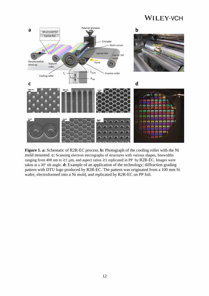
Figure 1. a: Schematic of R2R-EC process. b: Photograph of the cooling roller with the Ni
mold mounted. c: Scanning electron micrographs of structures with various shapes, linewidths
ranging from 400 nm to ≳1 µm, and aspect ratios ≳1 replicated in PP by R2R-EC. Images were
taken at a 30 tilt angle. d: Example of an application of the technology; diffraction grading
pattern with DTU logo produced by R2R-EC. The pattern was originated from a 100 mm Si
wafer, electroformed into a Ni mold, and replicated by R2R-EC on PP foil.

13
Figure 2. a: AFM images of Nano-pillar arrays replicated in PP. b: Single pillar extracted from
arrays in (a). c and d: AFM images of the corresponding Si master structures, array (c), and single
pillar (d). e: Average height of the pillars in (a). Error bars represent the standard deviations of heights
in the 2 µm × 2 µm scan-areas.

14
Figure 3. a: COMSOL simulation of temperature profile in the nip for 𝐹/𝑊 = 30 kN/m, 𝑇𝑐 = 70 C
and 𝑉𝑅 = 60 m/min. Right panel shows temperature profiles at nip entry for 𝑉𝑅 = 60 m/min , 40
m/min, and 10 m/min respectively. b: Pressure profile in the nip for different values of 𝐹/𝑊
calculated using Equation 1. c: Temperature profile extracted at different distances from the mold
surface from simulation in (a). d: Temperature profile extracted from simulation in (a) for different 𝑉𝑅
at 100 nm from the mold surface.

15
The table of contents entry
Fabrication of micro- and nanostructures at line-speed 60 m/min by large-area roll-to-roll
extrusion coating is demonstrated. Nanopillars with diameters 80 nm and heights 100 nm are
replicated in polypropylene. The main limiting factor for replication on nanoscale is the
retardation time for solidification of the melt. This surprisingly leads to better replication the
higher line-speed is used for crystalline polymers.
Keywords: Extrusion coating, roll-to-roll, nanostructure, supercooled polymer, surface
tension.
Swathi Murthy, Maria Matschuk, Qian Huang, Nikolaj K. Mandsberg, Nikolaj A.
Feidenhans’l, Peter Johansen, Lars Christensen, Henrik Pranov, Guggi Kofod, Henrik C.
Pedersen, Ole Hassager, Rafael Taboryski*
Fabrication of micro-nano structures by roll-to-roll extrusion coating
ToC figure

16
Copyright WILEY-VCH Verlag GmbH & Co. KGaA, 69469 Weinheim, Germany, 2013.
Supporting Information
Fabrication of micro-nano structures by roll-to-roll extrusion coating
Swathi Murthy, Maria Matschuk, Qian Huang, Nikolaj K. Mandsberg, Nikolaj A.
Feidenhans’l, Peter Johansen, Lars Christensen, Henrik Pranov, Guggi Kofod, Henrik C.
Pedersen, Ole Hassager, Rafael Taboryski*
Ni mold fabrication
Polymeric nano-micro structures presented in this paper were produced by roll-to-roll
extrusion coating of polymer melt against a structured nickel molds mounted on the cooling
roller. The Ni molds were fabricated by electroforming from a Si master. Depending on the
size of the structures, Si masters were fabricated either by deep ultra-violet lithogrphy (DUV)
or electron beam (e-beam) lithography, followed by subsequent deep reactive ion etching
(DRIE). For DUV lithography, various patterns with structure sizes in the range of 200 nm to
few microns were spin-coated with a thin film of the photosensitive resist KRF M230Y (JSR
Micro) and exposed using a DUV stepper (Canon FPA-3000 EX4). Structures smaller than
200 nm were spin coated by an e-beam resist ARN 7520 (ALLRESIST) and written by
electron beam writer (JEOL-JBX9500). Subsequent to pattern exposure and development, the
structures were etched into a Si wafer, by a Pegasus deep reactive-ion etching system (SPTS
Technologies Ltd.), using the exposed polymer film as an etch mask. After the removal of the
remaining resist film by oxygen plasma, a 20 – 100 nm thin film of nickel-vanadium alloy (7
wt% vanadium) was sputter coated (Polyteknik Cryofox Explorer 700), followed by
electroplating in a galvanic nickel bath to form 175 – 200 µm thick nickel molds (Technotrans
microform.200). Finally, nickel molds were coated with an FDTS antistiction layer to ease
demold from the Ni surface during extrusion coating. The Ni molds originating from DUV
lithogaphy were coated with a triple layer FDTS coating (Al2O3/SiO2/FDTS) by the Danish
Technological Institute, Taastrup, Denmark. Nickel molds made by electron beam lithography
were first coated with Al2O3 by atomic layer deposition (Picosun ALD model R200) and
subsequently with FDTS by molecular vapor deposition (Applied Microstructures Inc. MVD
100). The MVD process comprised the following: first a cycle with one injection of FDTS at
0.5 torr and one injection of water at 6 torr reacts for 15 minutes. Then the process chamber is
evacuated and a new cycle starts until 4 cycles are completed. A summary of the process steps
involved in the fabrication of Ni mold is presented in Figure S1.

17
Figure S1: Schematic diagram of the nickel mold fabrication
From Si master to replication in PP
Figure S2 shows the replication of nanopillars from Si master to Ni mold and finally the
nanostructured PP foil.
Figure S2. SEM images of nanostructures in Si master, Ni mold and PP foil fabricated by extrusion
coating.
Influence of polymer material
We observed a very robust process with respect to the applicability of a wide range of process
parameters yielding good replication for PP while other semi-crystalline polymers such as
polyethylene (PE), polyolefin (PO), and polymethylpentene required a more tightly optimized
process to replicate the very same features or did not replicate completely. For the parameter
range that was used in this investigation, it was not possible to achieve a visible replication of
structures in amorphous polymers such as polystyrene and cyclic olefin copolymer. In Figure

18
S3, the diffraction gratings have been completely replicated in PP, whereas PE shows
incomplete replication and PO shows almost no replication at all for the same process
conditions. In Figure S3, we see similar results, where the honey comb structures have been
well replicated in PP and poorly replicated in PO.
Figure S3. Focused Ion Beam-SEM images of diffraction gratings in nickel and replicas thereof, extruded
in PP, PE, and PO, replicated at 𝑽𝑹 = 20 m/min, 𝑻𝒄 = 30 C, and 𝑭 = 30 KN/m.
Influence of process parameters
Similar to injection molding and nano imprint lithography, in extrusion coating, we observed
a general trend of better replication quality with higher nip force (𝑭) and higher mold
temperature (𝑻𝒄). As shown in Figure S4, we observed complete replication of the diffraction
gratings in PP at 𝑭 = 30 kN/m, whereas only 60% replication at 𝑭 = 7 kN/m, with other
parameters kept constant.
Figure S4. SEM images of samples replicated in PP produced with low nip force (𝑭 = 7 kN/m) and high
nip force (𝑭 = 30 kN/m) at 𝑽𝑹 = 20 m/min and 𝑻𝒄 = 30 C
As shown in Figure S5, we observed complete replication of micro holes at 𝑻𝒄 = 70 C,
whereas we observed polymer flow lines, indicating incomplete replication, at lower
temperatures (30 C, 50 C).

19
Figure S5. SEM images (top view) of microholes extruded in PP replicated with increasing roller
temperature from left to right (𝑻𝒄 = 30, 50, 70 C) at 𝑽𝑹 = 10 m/min and 𝑭 = 30 kN/m. A clear
improvement of the replication quality, meaning reduction in flow line formation can be observed with
increasing temperature.
Influence of line-speed (𝑽𝑹)
The evaluation of the sole influence of the line-speed (𝑽𝑹) on the replication quality is not
straight forward since the change in velocity is associated with a change in the extruded
polymer film thickness. For larger structures (> 10 µm), the replication quality increased with
decreasing 𝑽𝑹 (Figure S6), for smaller microstructures (< 10µm), 𝑽𝑹 did not seem to have
dramatic influence on the replication quality (Figure S6). For nanostructures (< 200 nm), the
replication improved with increasing 𝑽𝑹 (Figure 2). For hierarchical structures (Figure S6c),
the replication of nanostructures was better at higher 𝑽𝑹, whereas for the microstructures 𝑽𝑹 did not seem to affect the replication quality.
Figure S6. Top row: SEM images (30° tilt), of diameter 𝒅 =11.4 µm microholes replicated in PP with
increasing 𝑽𝑹 from left to right 𝑽𝑹 = 10, 30, 60 m/min at 𝑻𝒄 = 30 C and 𝑭 = 30 kN/m. A clear
improvement of the replication quality (reduction of flow line formation) can be observed with increasing
𝑽𝑹. Bottom row: SEM images (30 tilt), of hexagonal microstructures of height 𝒉 = 1.45 µm extruded in
PP replicated with increasing 𝑽𝑹.from left to right 𝑽𝑹= 20, 50, 60 m/min at 𝑻𝒄 = 30° C and 𝑭 = 30 KN/m.
The average height of the sidewalls does not change significantly, though nanostructures on top of the
plateaus are worse replicated with increasing 𝑽𝑹.

20
DSC measurement of the static solidification temperature
The melting and solidification temperatures of PP-WF420HMS was determined by
differential scanning calorimetry (DSC) under standard heating/cooling/heating process
between -50° C and 200° C at a rate of 10° C/min. The measurements were performed using a
DSC-Q1000 differential scanning calorimeter from TA Instruments. The weight of the tested
sample was 6.05 mg. Nitrogen gas at a flow rate of 50 mL/min was used as the heating flow.
Figure S7 shows the results of the DSC measurements. The melting temperature of PP-
WF420HMS is found to be 162 C, whereas the crystallization temperature is around 123° C,
which is lower than the melting temperature.
Figure S7. Results of DSC measurements for PP-WF420HMS.
Finite element modelling of the temperature distribution in the nip
The finite element modelling of the temperature in the nip was made by finite element
analysis using COMSOL Multiphysics 5.0. The modelling was done using the time-
independent version of the convection-diffusion equation for heat, as we were interested in
the timely converged heat distribution. The heat transfer is thus solely simulated considering
forced convection and diffusion. This justifies modelling the molten polymer as a solid in
translation governed by Equation S1 as implemented in the standard COMSOL module ‘Heat
Transfer in Solids’ with translational motion:
𝜌𝐶𝑝𝒖 ∙ ∇𝑇 = ∇ ∙ (𝑘∇𝑇). (S1)
Here 𝜌 is the density, 𝐶𝑝 is the specific heat capacity at constant pressure, 𝒖 is the velocity
vector, 𝑇 the absolute temperature, and 𝑘 the thermal conductivity. We have collapsed the
problem into a 2-dimensional one since the 3rd
dimension parallel to roller axle has
translational symmetry in the region of interest. Equation S1 applies to each individual
material domain defined in Figure S8 with appropriate values for their thermodynamic
properties stated in Table S1.

21
Material
Thermal Property Ni PP PET
Thermal conductivity (𝑘, W
m∙K) 62 0.2 0.45
Density (𝜌, kg
m3) 9000 1000 950
Heat capacity (𝐶𝑝, J
kg∙K) 440 2300 1250
Table S1 Material properties used in the simulation.
Figure S8. Schematic drawing of the simulation showing the geometry, the applied boundary conditions,
and the material domains. The arrows indicate the direction of the translational motion.
The simulation has been made for 3 different line-speeds: 60 m/min, 40 m/min, and 10 m/min.
Dirichlet boundary conditions were applied far away from the regions of interest. Hence, the
inner part of the nickel roller was fixed at 70° C, the incoming PP melt at 295° C, and the
incoming PET carrier foil at 20° C. The bottom boundary of the full simulation domain was
made with thermal insulation conditions (dotted): 𝒏 ∙ (𝑘𝛻𝑇) = 0, where 𝒏 is the boundary
normal vector. This boundary condition was justified as the temperature of the melt had
almost stabilized when exiting the nip. Insulating boundary conditions were also applied
between the different materials domains at the polymer entrance to include the heat loss in the
polymer melt during the stretching path in the air. This was done in order to simulate the
highly insulating properties of air.
The simulation is carried out with a total number of 275.000 rectangular mesh elements with a
size distribution such that regions with the largest temperature variation is attributed the
smallest element size. Hence, the element size is set to change linearly, such that the smallest
size is set to ∆𝑥 × ∆𝑦 = 200 nm × 20 nm at the PP/Ni interface at the entrance of the melt in
the nip region, while the largest size was set to 36 µm × 4 µm in the PET region at the exit
from the nip. The 𝑥-direction is here taken along the nip length similar to the definition in
Equation 1, and the 𝑦-direction is along the thickness of the foil.