fabrication and manipulation of polymeric magnetic particles with magnetorheological … · ·...
TRANSCRIPT

Journal of Magnetism and Magnetic Materials 326 (2013) 220–224
Contents lists available at SciVerse ScienceDirect
Journal of Magnetism and Magnetic Materials
0304-88
http://d
n Corrnn Cor
E-m
weitz@s
journal homepage: www.elsevier.com/locate/jmmm
Fabrication and manipulation of polymeric magnetic particles withmagnetorheological fluid
Jaime Rodrıguez-Lopez a, Ho Cheung Shum b,n, Luis Elvira a,Francisco Montero de Espinosa a, David A. Weitz c,nn
a Centro de Acustica Aplicada y Evaluacion No Destructivos (CAEND), CSIC-UPM, C/Serrano 144, 28006, Madrid, Spainb Department of Mechanical Engineering, University of Hong Kong, 7/F Haking Wong Building, Pokfulam Road, Hong Kongc Department of Physics & School of Engineering and Applied Sciences, Harvard University, 9 & 15 Oxford Street, Cambridge, MA 02138, USA
a r t i c l e i n f o
Article history:
Received 2 April 2012
Received in revised form
20 June 2012Available online 15 September 2012
Keywords:
Magnetorheological fluid
Microfluidic
Polymeric particle
53/$ - see front matter & 2012 Elsevier B.V. A
x.doi.org/10.1016/j.jmmm.2012.09.009
esponding author. Tel.: þ852 2859 7095; fax
responding author. Tel.: þ1 617 496 9788.
ail addresses: [email protected], [email protected]
eas.harvard.edu (D.A. Weitz).
a b s t r a c t
Polymeric magnetic microparticles have been created using a microfluidic device via ultraviolet (UV)
polymerization of double emulsions, resulting in cores of magnetorheological (MR) fluids surrounded
by polymeric shells. We demonstrate that the resultant particles can be manipulated magnetically to
achieve triggered rupture of the capsules. This illustrates the great potential of our capsules for
triggered release of active ingredients encapsulated in the polymeric magnetic microparticles.
& 2012 Elsevier B.V. All rights reserved.
1. Introduction
Functional composite particles, which are made of an inor-ganic material incorporated to a polymer network, are of greatinterest to biotechnology, optics and cosmetics [1]. Specifically,microparticles with a magnetic core are widely used in manyapplications such as treatment of hyperthermia [2], drug delivery[3], contrast enhancement for magnetic resonance imaging [4]and fluid flow modifications [5]. The magnetic properties of thesematerials make them susceptible to a non-uniform external fieldand enable their manipulation under controlled magnetic field.The high potential of these particles can be further realized byimproving both the process of particle fabrication as well as thedevelopment of particles with new structures.
Microfluidic technologies offer an approach to create particlesusing emulsions as a template. With microfluidic devices, emul-sion drops are fabricated one drop at a time. One way to preparethese drops is by co-flowing two immiscible fluids for dropletformation; the resultant particles have high size uniformity. Inaddition, the size and shape of the created droplets can beconveniently varied by controlling the flow rates of the fluids.Moreover, the approach also enables fabrication of higher-orderemulsions such as water-in-oil-in-water (w/o/w) double emul-sions. If in the emulsion one of the phases is a polymer, the
ll rights reserved.
: þ852 2858 5415.
f.csic.es (H.C. Shum),
emulsions could be used as a template for generation of poly-meric particles [6].
To provide a magnetic behavior to the particles, one approachis to directly coat polymeric particles with a layer of magneticnanoparticles through surface chemistry techniques [7] or dis-persion polymerization [7,8]. Another approach is to encapsulatemagnetic nano- or micro- particles suspended in a carrier fluid ina polymeric matrix that form the particles. Common magneticparticle suspensions include magneto-rheological (MR) fluids andferrofluids. MR fluids are suspensions of magnetic particles in acarrier liquid with some additives to stabilize the medium.Particle sizes are between 1 and 10 mm, which are too heavy forBrownian motion to keep them suspended, so due to the differentdensities between the particles and the carrier fluid, particlestend to sediment in MR fluids. Due to the high sensitivity of themagnetic particles, MR fluids exhibit a rapid response when amagnetic field is applied. Typical response time is on the order ofmilliseconds [9]. The fast response time makes MR fluids suitableas dampers and shock absorbers in applications ranging fromhelicopters to prosthetic legs [10,11]. From the point of view ofthe inner structure, in the absence of an external field, a MR fluidis a suspension. When a magnetic field is applied; a magneticdipole moment is induced in the particles parallel to the magneticfield, and, as a result, particles tend to align to form orderedstructures. The application of this field causes the microstructureof the fluid to change from a liquid-like state to a more structuredstate, giving rise to significant variations not only in viscosity butalso in its inner order as exhibited by the particle rearrangement.At sufficiently high particle concentration, the original medium

J. Rodrıguez-Lopez et al. / Journal of Magnetism and Magnetic Materials 326 (2013) 220–224 221
turns from an isotropic state to an anisotropic state, whereparticles aggregate to form chain-like structures. However, ferro-fluids primarily consist of nano-size particles suspended in acarrier liquid so they are suspended by Brownian motion andgenerally will not settle. When a magnetic field is applied,Brownian motion prevents formation of a solid structure, so themechanical properties do not change as much as in a MR fluid.
In this work, polymeric magnetic microparticles are preparedusing a microfluidic device via UV polymerization of doubleemulsions in which the core is a MR fluid and the shell is apolymer. We demonstrate magnetically triggered release of theMR fluids from the core-shell microparticles.
2. Materials and methods
2.1. Materials
We prepare oil-in-water-in-oil (o/w/o) double emulsions astemplate for the polymeric magnetic microparticles. By adjustingthe flow conditions and the choice of materials involved, weform a stable double emulsion encapsulating the MR fluid in thecores. The inner phase in all experiments is a MR fluid providedby Liquid Research, with a 20% of volume fraction of carbonyliron particles from 1 to 10 mm suspended in a proprietary hydro-carbon oil. The continuous phase is a PDMS oil with surfactantDow Corning 749 at 2% w/w for stabilizing the emulsion, whilethe shell of the double emulsions consists of a photoinitiatorof Darocur 1173 (Ciba) at 5% w/w, oligomer and surfactantat optimized concentrations for stable double emulsions. PEGDimethacrylate (Sigma-Aldrich) and PEG Diacriyate (Sigma-Aldrich)were tested as oligomers while Tween 20 (EMD), Tween 80(Sigma-Aldrich), Pluronic L121 (BASF) or Pluronic 168 (BASF)were added at weight fractions of 2% w/w or 5% w/w for emulsionstabilization.
2.2. Capillary microfluidic devices
A glass capillary device is used for making double emulsions.Capillary microfluidic devices consist of coaxial assemblies ofglass capillaries on glass slides [6,12]. The advantages of thesedevices are that the wettability can be easily controlled by asurface reaction with an appropriate surface modifier and thecapability of creating three dimensional flows easily. Specifically,the device used in this work consists of two circular capillaries,
Fig. 1. (a) Schematic of a capillary microfluidic device for generating d
one for the inner fluid and the other one for collection of theprepared emulsions, arranged end-to-end within a square capil-lary. The inner diameter of the square capillary is about 1.05 mmand the outer diameter of the circular capillaries is 1 mm. Wealign these capillaries under an optical microscope to achievecoaxial configurations of them. The capillaries are tapered using amicropipette puller (Sutter Instruments) to achieve desired dia-meters of them. In a typical device in this work, the tip diametersof the collection tube and the inner capillary are about 240 mmand about 120 mm respectively. The nozzle size of the capillarieshas been optimized to avoid clogging of the nozzle by the MRfluids. Another important parameter is the distance between thecapillaries; in this work, the distance between the capillaries isabout 180 mm. To avoid clogging and to form the double emulsiondrops continuously, the distance between the capillaries and thesize of the tip of the inner capillary must be at least a hundredmicrons. These dimensions are larger than those in typicalcapillary microfluidic devices for creating double emulsions withfluids with viscosities close to that of water.
To generate double emulsions, the inner fluid is pumpedthrough the tapered circular capillary while the middle fluid,which is immiscible with the inner and outer fluids, flows throughthe interstices between the square capillary and the capillary forthe inner fluids in the same direction as the flow of the innerfluids. The outermost fluid flows through the interstices of thesquare capillary and the collection capillary in the directionopposite to the flow of the inner and middle fluids. When thethree fluids enter the collection tube, a double emulsion isformed, as shown schematically in Fig. 1a and in the opticalmicroscope image in Fig. 1b.
We use syringes (Hamilton gastight, 10 cc) for injecting thefluid phases. The flow rates were controlled with syringe pumps(Harvard Apparatus). The range of flow rates used is 1750–2000 mL/h for the outer phase, 500–600 mL/h for the middle phaseand 75–100 mL/h for the inner phase. Due to the high volumefraction of the inner phase and therefore the high viscosity, theflow rate of the inner phase has to be low to avoid pressurebuildup that leads to breakage of the syringes during operation.Among the three different phases, the stability of the doubleemulsion generation is most sensitive to changes in the flow rateof the inner phase. For instance, when the flow rate of the innerphase is higher than 200 mL/h, double emulsions fail to form.
With the appropriate device geometry and fluid flow rates,monodisperse double emulsions can be stably and reproduciblygenerated for as long as 3 h.
ouble emulsions; and (b) optical micrographs of a device at work.
J. Rodrıguez-Lopez et al. / Journal of Magnetism and Magnetic Materials 326 (2013) 220–224222
The formation of double emulsion is visualized using a highspeed camera (Phantom V5, Vision Research) connected to amicroscope.
2.3. Polymerization process
Double emulsions are solidified after polymerization of thedroplet phases containing photocrosslinkable monomers initiatedusing UV light. Depending on the composition of the doubleemulsion, the polymerization time varies from 7 min, when PEGdiacrylate is used, to 25 min, when PEG dimethacrylate is used. Toavoid clogging of the device, stray UV light needs to be preventedby covering the entire device with aluminum foil except for areaswhere UV-induced polymerization should take place. FollowingUV illumination at 254 nm, polymeric particles are formed.
The images of the polymeric particles moving are acquired bya separate video camera (Nikon DS-Fi1) connected to a micro-scope. The magnetic field is applied with a permanent magnet.
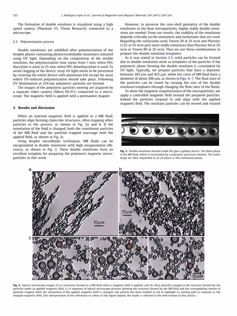
Fig. 3. Double emulsions formed inside the glass capillary device. The black phase
is the MR fluid, which is surrounded by a polymeric precursor solution. The entire
drops are then suspended in an oil phase as the continuous phase.
3. Results and discussion
When an external magnetic field is applied to a MR fluid,particles align forming chain-like structures, often trapping otherparticles in the process, as shown in Fig. 2a and b. If theorientation of the field is changed, both the constituent particlesof the MR fluid and the particles trapped rearrange with theapplied field, as shown in Fig. 2c.
Using droplet microfluidic techniques, MR fluids can beencapsulated in double emulsions with high encapsulation effi-ciency, as shown in Fig. 3. These double emulsions form anexcellent template for preparing the polymeric magnetic micro-particles in this work.
Fig. 2. Optical microscope images of (a) structures formed in a MR fluid when a magn
particles under an applied magnetic field. (c) A sequence of optical microscope picture
particles trapped when the orientation of the applied magnetic field is changed, one
changed magnetic field. (For interpretation of the references to colour in this figure le
However, to preserve the core-shell geometry of the doubleemulsions in the final microparticles, highly stable double emul-sions are needed. From our results, the stability of the emulsionsdepends critically on the monomers and surfactants that are used.Regarding the surfactants used, Tween 20 at 2% w/w and PluronicL121 at 5% w/w give more stable emulsions than Pluronic 64 at 5%w/w or Tween 80 at 2% w/w. Thus we use these combinations toprepare the double emulsion templates.
As it was stated in Section 2.3, solid particles can be formeddue to double emulsions work as templates of the particles if thepolymeric phase forming the double emulsion is crosslinked byUV light. Typically, we prepare particles that have a diameterbetween 385 mm and 425 mm, while the cores of MR fluid have adiameter of about 200 mm, as shown in Figs. 4–7. The final sizes ofthe particles can be tuned by varying the size of the doubleemulsion templates through changing the flow rates of the fluids.
To show the magnetic responsiveness of the microparticles, weapply a controlled magnetic field around the prepared particles.Indeed the particles respond to and align with the appliedmagnetic field. The resultant particles can be moved and rotated
etic field is applied, and (b) silica particles trapped in the structure formed by the
s showing the structure formed by the MR fluid and the corresponding motion of
particle has been marked in red to highlight its moving path in response to the
gend, the reader is referred to the web version of this article.).

Fig. 4. Optical microscope images illustrating the motion of the polymeric magnetic microparticles in response to an applied magnetic field. This motion is controlled by
changing the position of a permanent magnet. The red arrows indicate the orientation of the magnetic field applied to actuate the particle. For example, the particle moves
from position 1 to position 2 because a magnetic field is applied with an orientation from left to right. The rectangular outline has an area of 1000 mm�600 mm.
(For interpretation of the references to colour in this figure legend, the reader is referred to the web version of this article.)
Fig. 5. Optical microscope images illustrating the rotation of the polymeric magnetic microparticles under a rotating magnetic field. The red arrows indicate the rotational
direction of the applied magnetic field. The rectangular outline has an area of 1000 mm�600 mm. (For interpretation of the references to colour in this figure legend, the
reader is referred to the web version of this article.)
Fig. 6. (Left) Optical microscope image of a polymeric magnetic particle in the
absence of a magnetic field. (Right) Optical microscope image of a polymeric
particle following the release of the inner magnetic phase due to the application of
an inhomogeneous magnetic field.
J. Rodrıguez-Lopez et al. / Journal of Magnetism and Magnetic Materials 326 (2013) 220–224 223
under corresponding magnetic fields, as shown in Figs. 4 and 5respectively. Thus, these particles can be used for magneticactuation.
Apart from movements, the microparticles prepared in thismanner can also be triggered to break with an appropriatemagnetic field. In the absence of a magnetic field, the micro-particles remain intact without any release of the components inthe core, as shown in the left image of Fig. 6. However, when anapplied magnetic field increases beyond a certain threshold, theshell of the microparticles becomes broken, releasing the materi-als inside, as shown in the right image of Fig. 6.
The complete release of the inner MR fluids is confirmed bythe lack of response upon subsequent application of the same

Fig. 7. Sequence of optical microscope images showing the lack of motion exhibited by polymeric particle after the MR fluids are released. Only a slight motion by small
amount of MR fluids remaining inside the microparticles is observed. The red arrows show the rotational direction of the applied magnetic field. This confirms the
effectiveness of our approach for triggering the release of the MR fluids and other potential active ingredients. (For interpretation of the references to colour in this figure
legend, the reader is referred to the web version of this article.)
J. Rodrıguez-Lopez et al. / Journal of Magnetism and Magnetic Materials 326 (2013) 220–224224
magnetic field that would have led to motion of the microparticles,as shown in Fig. 7. This suggests a way to trigger release of activecomponents from capsules.
4. Conclusion
Using a capillary microfluidic device, we achieve a stabledouble emulsion encapsulating a MR fluid. The shell of the doubleemulsions consists of an oligomer, surfactant and photoinitatiorwhile the continuous phase is a PDMS oil with surfactants forstabilizing the emulsion. By photo-polymerizing the doubleemulsion templates with ultraviolet (UV) light, we form solidcore-shell microparticles. Due to the presence of magnetic parti-cles suspended in the encapsulated MR fluids, these polymericparticles can be easily manipulated with an external magneticfield.
By varying the intensity and uniformity of the magnetic field,the capsules can be cracked. The MR fluids released form chain-like solid structures outside the microparticles. This changes thelocal viscosity of the fluid and in some cases, cause a blockageinside the channels. Thus, these core-shell particles could be usedas capsules for delivering the MR fluids to target locations wherethe release of the MR fluids can change the local characteristics ofthe fluids. Furthermore, these capsules can also be used forencapsulating other active materials which are released togetherwith the MR fluids upon application of an appropriate magneticfield.
Acknowledgments
This work was supported by a CSIC JAE fellowship, the NSF(DMR-1006546), the Harvard MRSEC (DMR-0820484), the NSFC(20676068) and the Seed Funding Programme for Basic Researchfrom the University of Hong Kong (201101159009).
References
[1] C.H. Chen, A.R. Abate, D. Lee, E.M. Terentjev, D.A. Weitz, Advanced Materials21 (2009) 3201–3204.
[2] A. Jordan, R. Scholz, K. Maier-Hauff, M. Johannsen, P. Wust, J. Nadobny,H. Schirra, H. Schmidt, S. Deger, S. Loening, W. Lanksch, R. Felix, Journal ofMagnetism and Magnetic Materials 225 (2001) 118–126.
[3] P.A. Voltairas, D.I. Fotiadis, L.K. Michalis, Journal of Biomechanics 35 (2002)813–821.
[4] M. Hoehn, E. Kustermann, J. Blunk, D. Wiedermann, T. Trapp, S. Wecker,M. Focking, H. Arnold, J. Hescheler, B.K. Fleischmann, W. Schwindt, C. Buhrle,Proceedings of the National Academy of Sciences of the United States ofAmerica 99 (2002) 16267–16272.
[5] J. Liu, JSME International Journal, Series B: Fluids and Thermal Engineering45 (2002) 55–60.
[6] R.K. Shah, H.C. Shum, A.C. Rowat, D. Lee, J.J. Agresti, A.S. Utada, L.Y. Chu,J.W. Kim, A. Fernandez-Nieves, C.J. Martinez, D.A. Weitz, Materials Today11 (2008) 18–27.
[7] H. Kawaguchi, Progress in Polymer Science 25 (2000) 1171–1210.[8] B.J. Park, M.S. Kim, H.J. Choi, Materials Letters 63 (2009) 2178–2180.[9] G. Bossis, S. Lacis, A. Meunier, O. Volkova, Journal of Magnetism and Magnetic
Materials 252 (2002) 224–228.[10] J.D. Carlson, D.M. Catanzarite, K.A.S. Clair, International Journal of Modern
Physics B 10 (1996) 2857–2865.[11] B.J. Park, F.F. Fang, H.J. Choi, Soft Matter 6 (2010) 5246–5253.[12] A.S. Utada, E. Lorenceau, D.R. Link, P.D. Kaplan, H.A. Stone, D.A. Weitz, Science
308 (2005) 537–541.