fabrication and assembly of an array of micro fuel
TRANSCRIPT

Louisiana State UniversityLSU Digital Commons
LSU Master's Theses Graduate School
2004
Fabrication and assembly of an array of micro fuelinjector nozzles for a trapped-vortex combustorTracy Ettel MorrisLouisiana State University and Agricultural and Mechanical College, [email protected]
Follow this and additional works at: https://digitalcommons.lsu.edu/gradschool_theses
Part of the Mechanical Engineering Commons
This Thesis is brought to you for free and open access by the Graduate School at LSU Digital Commons. It has been accepted for inclusion in LSUMaster's Theses by an authorized graduate school editor of LSU Digital Commons. For more information, please contact [email protected].
Recommended CitationMorris, Tracy Ettel, "Fabrication and assembly of an array of micro fuel injector nozzles for a trapped-vortex combustor" (2004). LSUMaster's Theses. 1150.https://digitalcommons.lsu.edu/gradschool_theses/1150

FABRICATION AND ASSEMBLY OF AN ARRAY OF
MICRO FUEL INJECTOR NOZZLES FOR
A TRAPPED-VORTEX COMBUSTOR
A Thesis
Submitted to the Graduate Faculty of the Louisiana State University
Agricultural and Mechanical College in partial fulfillment of the
requirements for the degree of Master of Science in Mechanical Engineering
in
The Department of Mechanical Engineering
by Tracy Ettel Morris
B.S., Louisiana State University, 1996 May 2004

ii
To my husband Chad
And my children
Brooke, Sidney, and Cole

iii
Acknowledgements
I would like to thank the Louisiana Board of Regents/LEQSF under agreement
NASA/LSU-91-96)-01 and NASA/LASPACE under grant NGT5-40035 for their
contributions. Their support is gratefully acknowledged.
This work was supported in part by the AFOSR/LEQSF DESCOR grant F49620-
98-1-0476 with Dr. Julian Tishkoff as the contract monitor.

iv
Table of Contents
Dedication…………………………………………………………………………… Acknowledgements…………………………………………………………………. Abstract……………………………………………………………………………… Chapter 1: Introduction……………………………………………………………...
1.1 Focus…………………………………....................................... 1.2 Motivation……………………………………………………... 1.3 Device Requirements………………………………………….. 1.4 Preview of Fuel Injector Design………………………………. 1.5 Thesis Outline………………………………………………….
Chapter 2: Background……………………………………………………………...
2.1 Combustors …………………………………………………… 2.2 Atomizers……………………………………………………… 2.3 Compressible Fluids…………………………………………... 2.4 Incompressible Fluids…………………………………………. 2.5 Plate Deflection……………………………………………….. 2.6 Cantilever Deflection………………………………………….. 2.7 UV-LIGA……………………………………………………… 2.8 Electrodeposition…………………………………………….…
Chapter 3: Material Selection………………………………………………………..
3.1 Metals………………………………………….………………... 3.2 Ceramics………………………………………………………… 3.3 Conclusion……………………………………………………….
Chapter 4: Metal Fuel Injector Prototype……………………………………………
4.1 Calculations…………………………………………………….. 4.2 Prototype Design………………………………………………... 4.3 Prototype Fabrication……………………………………………
Chapter 5: Ceramic Solutions………………………………………………………. Chapter 6: Recommendations……………………………………………………….
6.1 Lapping…………………………………………………………. 6.2 Microfabrication Techniques…………………………………… 6.3 Contrast of Alignment Marks…………………………………… 6.4 Plate Thickness………………………………………………….
References……………………………………………………………………………
ii
iii
vi
111468
999
111920212124
26263135
37376085
145
156156156158159
160

v
Appendix A: Data Sheets...…………………………………………………………. Appendix B: Shop Drawings……………………………………………………...... Vita…………………………………………………………………………………...
163
165
173

vi
Abstract
An array of four fuel injector nozzles, each with micrometer-scale swirlers and a
microhole, is created on a single coupon. The nozzles are intended to atomize fuel to
blend with swirling air before ejecting into a trapped-vortex combustion chamber. A
first-generation metal prototype is fabricated in order to form the micro features, supply
the fuel and gas to the nozzles, and guide the mixture to the combustion chamber.
Microfabrication methods and precision machining are used to create a multiple
plate laminate assembly. The central plate contains the four microholes, which atomize
the fuel, and facilitate the swirler structures needed to induce vorticity in the fuel and air.
Fabrication of the swirlers requires electrodeposited nickel microstructures on both sides
of the plate in order to segregate the high-pressurize air and fuel flows. Two other plates
seal the air and fuel channels resulting in separate reservoirs for supply to the
microstructures. A fourth plate defines a low-pressure complementary air reservoir
needed for stoichiometric conditions.
Guided with alignment pins, the plates fasten together to seal the reservoirs and
guide the injecting mixture along an axis with a total alignment error of less than 50 µm.
Precision machining is needed to drill the holes required for alignment, fluid flow, and
fasteners. Plunge EDM drilling through a thin plate creates the conically-shaped holes
75 µm -125 µm in diameter.
The project resulted in fully reproducible microfabrication methods, which when
used in coordination with precision machining techniques produces smooth, level
microstructures on both sides of the drilled nickel plate. The components were
assembled and tested for leakage. Since the prototype leaked below atmospheric

vii
pressure, the warped central plate could not be salvaged for patterned flow testing
purposes. Recommendations for the next generation prototype are presented.
Preliminary investigation of a ceramic prototype is conducted with particular
interest in sealing solutions involving cofired test samples. Viable testing methods and
specimen geometry are investigated. Future ceramic prototype development requires
shear joint testing as the initial step in realizing a self-sealing ceramic fuel injector
prototype.

1
1 Introduction
1.1 Focus
The objective of this thesis was to fabricate and assemble a prototype array of fuel
injector nozzles for subsequent study in high temperature flow-pattern analysis.
Micrometer scaled atomizing nozzles were needed to generate reduced droplet sizes in
order to improve combustion efficiency and reduce emissions. Swirler geometry was
used to generate a swirling mixture of atomized fuel and air for immediate injection into
the combustion chamber. A metal prototype assembly was the predecessor for a ceramic
version, which may assist in sealing and perform better in the high temperature
environment.
The long-term goal of this project was to produce many tiny fuel injector nozzles
for use in a trapped-vortex aircraft combustor to improve combustion efficiency while
meeting requirements for emissions control.
1.2 Motivation
Modern combustor designers balance two traditionally competing areas:
efficiency and emissions. Emissions legislation has led to increased research in the
reduction of pollutants found in exhaust. Past efforts to improve combustion efficiency
resulted in elevated combustion temperatures, which increased the release of toxic
products and violated today’s standards for emissions. Alternative approaches to
improve combustion efficient within emissions guidelines include eliminating unstable
combustion, or ‘flame-out’.

2
Flame stability directly affects efficiency since stability improvement results in
more complete combustion, which increases the power delivered for thrust and enhances
combustion uniformity. Combustion homogeny leads to a more uniform temperature
profile, which reduces resulting harmful emissions. Through elimination of cooler spots
during combustion, partially combusted harmful products, such as carbon monoxide (CO)
and unburned hydrocarbons (UHC), are reduced. Similarly, reduction of hot areas
reduces the formation of oxides of nitrogen (NOx) in the exhaust. Thus, through
enhanced flame stability during combustion, both fuel efficiency and emission quantities
can be improved.
Improved flame stability enhances the performance of aircraft combustors as they
operate through a wide range of environmental and operational conditions. Atmospheric
conditions change rapidly during descent and climb. The engine must not flame-out or
generate excessive flame temperatures while adjusting to continuously varying fuel flow
associated with acceleration. Additionally, reduction of pressure, temperature, and
density of the incoming air with increasing altitude requires flexibility in combustor
operations. Combustion must be stable over a wide range of chamber pressures due to
pressure differentials with change in altitude and forward speed. The air/fuel ratio
conventionally varies from 60:1 to 120:1 for simple cycle gas turbines in aircraft (Cohen,
1996). Compared to the combustive stoichiometric ratio of 15:1, high dilution is required
in order to maintain temperatures below those required for acceptable metallurgical
conditions of the turbine. Additionally, poor combustion can set up aerodynamic
vibration, which reduces the life of the chamber and causes blade vibration problems
(Harmon, 1981).

3
A solution that improves both fuel efficiency and emissions through increased
flame stability in the primary combustion chamber is to generate recirculation zones and
fuel atomization within a secondary combustion chamber. Atomization has the potential
to address flame instability and fuel efficiency through promotion of complete
combustion by vaporizing the liquid fuel into finer droplets. The decreased droplet size
increases total surface area, resulting in reduced vaporization time. This process
effectively increases residence time of the prepared combustive reactants within the
combustion chamber, increasing combustion and fuel efficiency (Harmon, 1981).
Atomization improvements have been achieved through creative fuel injector
nozzle design. Conventionally, fuel injector nozzles are comprised of a small hole
through which fluid is axially forced at elevated pressures. The resulting spray geometry
is usually conical as it enters the combustion chamber. The use of modified nozzle
geometries and micrometer-scaled atomizing orifices has improved nozzle design
(Simmons & Harvey, 1995).
Recirculation zones are conventionally used in combustors to increase flame
stabilization by sending the burning air/fuel mixture into a swirling flow pattern.
Increasing residence time within the chamber so that there is sufficient time for complete
combustion generates a self-piloting flame in the air stream. Directing a portion of the
burning air/fuel mixture back onto the incoming fuel and air creates these recirculation
zones.
There are many unique and creative solutions for producing recirculation zones
(Harmon, 1981). One of these methods is referred to as a trapped-vortex combustor,
since a secondary combustor is specifically sized to create recirculation zones to trap a

4
flame for subsonic speed flows. Continual injection of air and fuel into the vortex
maintains a stable flame for reliable ignition of combustion gases in the primary
combustion chamber.
1.3 Device Requirements
Specifications for fuel injector design were created in order to obtain a
predetermined droplet size for the atomized fuel and to generate vorticity in the fuel/air
mixture flow pattern as it exits the fuel injector. These values were determined from
experience and results collected through research on gas turbine combustors and fluid
dynamics within combustors. The primary function of the fuel injector was to atomize
the fuel as it passed through a microhole. The microhole was required to have a conical
geometry with 50 µm fuel inlet diameter and 100 µm exit diameter. This orifice was
expected to vaporize the fuel into droplet sizes of approximately 10 micrometers.
A swirler was created to induce vorticity in the fluid mixture as it was injected
subsonically into the combustion chamber. The swirlers were produced on both ends of
the micro-hole in order to combine the swirling, atomized fuel with swirling air. A
rendering of the specified swirler is shown in Figure 1.3(a). A swirler was composed of a
number of channels converging tangentially into a swirl chamber. The fluid moved into
the channels, achieving fully-developed flow before entering the swirl chamber. Within
the swirl chamber the fluid moved tangentially about the circular cavity. The fuel then
entered the micro-hole where it was atomized and developed a vortical profile induced by
the swirling motion in the swirl chamber. Upon exiting the hole, the vaporized fuel
blended to flow in the same direction with swirling air that was moving through a second
swirl chamber. The mixture then exited into the combustion chamber with the vortical

5
fluid profile. A nozzle, as referred to in this project, encompassed the microhole with
fuel and air swirlers located at each end of the connecting port.
The fully-developed flow criterion was used to improve vorticity in the mixture
flow pattern as it was ejected into the combustion chamber. Accurate alignment of the
microhole and the swirl chamber was required in order to achieve a proper flow pattern
upon injection. Minimization of the travel path length from the fuel swirler to the
combustion chamber was also necessary. This passage distance was expected to affect
flow patterns of the air/fuel mixture within the combustion chamber.
The combustor must withstand elevated temperatures and pressures and contain
gases emanating as products of combustion. By-products of corrosion must not plug the
microhole over the short life of the prototype, which was projected to be less than 100
hours. Design pressure in the combustion chamber was six atmospheres (607 kPa),
which was the maximum expected pressure. Structural deformation and subsequent
leakage at the design temperature were prohibited. The design temperature was
originally limited to 1200°C. As the project progressed and compromises were required
for fabrication purposes, the prototype design temperature was lowered to 600°C.
Figure 1.3(a) Rendering of a swirler with four channels converging tangentially into the swirl chamber. In this view, the swirl chamber diameter is the same as the atomizing hole diameter.
Swirler channels
Swirl chamber
Atomizing microhole

6
Combustion reactants in this gas turbine engine were oxygen and a high-
performance liquid jet fuel. The anticipated fuels were kerosene (JP4) and ethanol. JP4
is a wide cut version of kerosene, which was developed for military purposes to yield the
maximum volume percentage on crude oil (up to 40%). It has good relighting properties
and reduced aromatic content for reduction of the smoke point. The high flash point
(38°C) is safe for refueling and the low freezing point (-47°C) is adequate for high
altitude flying and good water separation characteristics (Hobson, 1984).
Due to the difficulty in obtaining acceptable flow rates from a system in which the
fuel passes through an orifice 50 µm in diameter, 0.13 mL/s (0.125 gal/hour) was
established as the minimum fuel flow rate. Extraction of air flow rates for complete
mixing of the two fluids and stoichiometric requirements for lean combustion were
required. The amount of air passing through the air swirler chamber for mixing with the
atomized fuel was not required to be stoichiometric. Alternatives were explored for
injecting the remaining required air into the combustion chamber. Subsonic injection of
the mixture into the combustion chamber was preferred.
1.4 Preview of Fuel Injector Design
A cross-sectional view of a single nozzle is shown in Figure 1.4(a). Fuel swirlers
were located on the lower end of the passage, and air swirlers were located on the
opposite end. Multiple plates were designed with reservoirs to contain the high pressure
fuel and air separately before mixing. As shown in Figure 1.4(b) the reservoirs were
sealed through a laminated plate assembly. The swirling air/fuel mixture was designed to
bypass the remaining plates and inject into the combustion chamber. Stoichiometry was

7
controlled by low pressure air, which was contained in a third reservoir and injected into
the combustion chamber adjacent to the mixture exit.
Each plate in the laminated plate assembly shown in Figure 1.4(b) had features
required for proper function of the micro-nozzle array. Plate C contained the micro hole
and interfaced with the swirlers. Plate B and Plate D also interfaced with the air and fuel
swirlers, respectively. Plate A provided outlets for the air/fuel mixture and the
complementary low-pressure air, along with containing Reservoir 1. Reservoirs 2 and 3
were located on the top and bottom sides of Plate C, respectively.
Figure 1.4(a) Cross-sectional view of swirlers mounted on both sides of connecting hole.
Figure 1.4(b) Cross-section of two fuel injector nozzles. Arrows indicate the direction of fluid movement.
Fuel High Pressure AirLow
Pressure Air
Plate A Plate B Plate C Plate D
Detail in Figure
Air swirlers
Fuel swirlers

8
1.5 Thesis Outline
The background is discussed to introduce previous and existing work on
combustors, atomizers, microfabrication, and electroplating. Material selection is then
reviewed for both metals and ceramics. The document then divides into two parts: metal
prototype and ceramic testing. Calculations, modeling, component design, and
fabrication methods are presented for the metal version. Ceramics are then discussed to
indicate the direction of subsequent research on design for material properties and testing
for bond strength. Finally, recommendations for future work on improving the fuel
injector design and fabrication are discussed.

9
2 Background
2.1 Combustors
Trapped-vortex (TV) combustors have been the subject of recent study due to
their potential for increased combustive efficiency through various design modifications.
The concept of trapped-vortex as applied to combustors was originally investigated by
Hsu, et al. (Hsu, 1995). This study described use of two discs placed in tandem and
housed in a cylindrical shell with annular air flowing over the front disc. In this
configuration, a vortex of annular gases was trapped in the cavity formed between the
discs. The focus of this and a subsequent study (Hsu, 1998) included determining the
dependence of the flame structure upon the optimal distance between the two discs for
production of a stable vortex over a large operation range. Katta and Roquemore (1996)
described a numerical investigation of vortex dynamics in TV cavities of various sizes in
low temperatures and combusting environments. Their follow up study (Katta and
Roquemore, 1998) used a numerical simulation to investigate the vortex dynamics of a
cavity into which fluid mass was directly injected. It was found that mass injection
increased the optimum width-to-diameter size ratio of the cavity. Most recently, an
experimental study on a TV combustor determined results of varying flow rates (injection
and annular) and injection orientation (Mancilla, et al., 2001). This study confirmed
reduced lean blow out for the combustor over a wide range of airflow rates, and
improvement of mixing without disrupting the trapped vortex by tangential injection.
2.2 Atomizers
Atomization can be accomplished by forcing high-pressure fuel through a small
orifice, resulting in a conical spray of fine droplets into the combustion chamber. A

10
Sauter mean diameter (SMD) of 50–100 µm is the typical size of atomization holes in
fuel injector nozzles for most aircraft gas turbine combustors (Cohen, & Saravanamuttoo,
1996). As the droplet size decreases, evaporation time within the combustion chamber
decreases, allowing more time for combustion reactions to occur with the vaporized fuel.
This increased residence time provides more complete combustion than if the fuel were
injected in larger droplets. Decreased amounts of unburned hydrocarbons (UHC) and
carbon monoxide (CO) in the exhaust result from vaporized fuel.
Conventionally machined atomizers are expensive to manufacture due to the
required precision and low repeatability of conventional methods. Microfabrication
procedures provide the required dimensional precision for arrays of atomizers, resulting
in reduced cost. A group at Case Western Reserve University, in collaboration with
Parker-Hannifin, (Simmons et al, 1995) patented an atomizer formed using a deep
reactive ion etching (DRIE) technique. UV lithography on a stainless steel substrate was
used to form the double-sided mask pattern. The straight microhole diameters ranged
from 50 µm to 2.5 mm with a 150 µm depth. The patent did not specify swirler channels
size or a means to supply the injectors with fluids. Subsequent work by this group
included optimization of atomizer geometry to produce minimal SMD values with
maximum spray angles and flow rates (Singh, Mehregany, Phillips, Harvey, & Benjamin,
1996). These atomizers were similarly etched with a two step mask process on both sides
of a 400 µm thick silicon substrate. Predicted corrosion problems led to the conclusion
that silicon was not an acceptable material for gas turbine atomizers. Another study of
this nozzle by members of the same group investigated the methods of coating the silicon
atomizer with 3C-SiC ceramic layers by atmospheric pressure chemical vapor deposition

11
(APCVD) (Rajan, Zorman, Mehregany, DeAnna, & Harvey, 1997). In performance tests
the coated atomizers demonstrated superior performance and withstood corrosion better
than the uncoated silicon versions. The latest study used improved ceramic deposition
rates (25 to 50 µm/hr) to create solid SiC atomizers of the previously tested geometry
(Rajan, Mehregany, & Stefanescu, 1999). This study also compared the ceramic
atomizer to an electroless nickel atomizer formed in another etched silicon mold, a LIGA
nickel version, and another silicon atomizer. SiC and the nickel atomizers exhibited
similar flow performance to the silicon devices; however, the SiC had superior in
corrosive wear resistance.
2.3 Compressible Fluids
Compressible fluid dynamics were used to determine the dimensions of the air
swirler channels, supply pressures, and resulting flow rates of the compressed air. A
guideline to determining these parameters was the criterion of achieving fully-developed
flow of the compressed air before entering the swirl chamber. Definitions of model
features are presented in this section and the results are discussed in Section 4.1.
2.3.1 Hydraulic Diameter
Calculations for ducts of noncircular cross section may be performed by using the
hydraulic diameter. Hydraulic diameter is a simplification used for ducts of noncircular
geometry in order to use relations derived for circular cross sections. The hydraulic
diameter of a rectangular duct is calculated with Equation 2.3.1,
Dh =
hwwh2+
2.3.1
where Dh is the hydraulic diameter and w and h are the channel width and height,
respectively.

12
In order to correlate equations meant for circular cross sections with non-circular
geometries, the error involved for the hydraulic diameter simplification must be
determined experimentally. Calculations of Reynolds number with values extracted from
this hydraulic diameter and duct surface roughness values from the Moody chart were
compared to experimental results. The accuracies of these calculations were within 15%
(Munson, 1990).
2.3.2 Reynolds Number
The Reynolds number (Re) is a dimensionless parameter reflecting the ratio of
inertial forces to viscous forces. It is calculated with Equation 2.3.2,
Re =
νρ hvD 2.3.2
where ρ is fluid density, v is velocity of the developed fluid, and ν is fluid
viscosity. For compressible fluids, most of these parameters vary with pressure and
temperature. These fluid properties may be solved through modeling of the flow through
the ducts.
The Reynolds number was used to determine whether the flow was laminar or
turbulent. The actual transition from laminar to turbulent flow within a pipe can occur at
various Reynolds numbers. The precise point of transition can be difficult to predict
since it depends on how much the flow is disturbed by pipe vibrations, surface
conditions, and other phenomena. For general engineering purposes, the values in Table
2.3.1 indicate the range of Reynolds number for corresponding flow conditions.
Table 2.3.1 Generalized flow conditions as estimated by Reynolds number (Munson, 1990).
Re < 2100 Laminar 2100 < Re < 4000 Transitional
Re > 4000 Turbulent

13
2.3.3 Fully-Developed Flow and Entrance Region
Fully-developed flow refers to the condition of fluid flow in an enclosed pipe in
which the velocity profile is a function only of the radial distance from the pipe center.
The entrance region of a closed channel is the portion in which the fluid transitions
between being independent of the pipe to being exclusively influenced by pipe geometry.
The fluid is assumed to enter the channel with a uniform profile, as shown in Figure
2.3(a). A no-slip boundary between the channel walls and a thin layer of fluid along the
channel walls is initialized at the pipe entrance and extends the length of the pipe. As the
fluid travels through, the boundary layer thickness increases. If the pipe is long enough,
the boundary layer extends radially, eventually filling the entire cross-sectional area of
the pipe. At this location along the pipe length, the entrance region ends and
hydrodynamic fully developed conditions are achieved.
The length of the entrance region was a guideline for determination of the channel
length for the air swirlers. The design criterion requires fully developed flow of the
compressed air exiting each swirler duct. The entrance length depends on fluid
conditions, flow characteristics, and channel cross-sectional area. The entry length, Le,
can be calculated with Equation 2.3.3 for turbulent flow.
Le = ( ) 6/1h ReD4.4 2.3.3
Figure 2.3(a) Hydrodynamic developing flow in an enclosed channel.
Fully-developed
Entrance region
Le
r x

14
2.3.4 Friction Factor
The friction factor is a parameter required for the Fanno flow analysis, which is
presented in Section 2.3.9. Sidewall surface roughness was reflected in the friction
factor, which was approximated by using the Moody chart (Munson, 1990). The Moody
chart plots Reynolds number with surface roughness in order to extract the
experimentally determined friction factor.
2.3.5 Ideal Gas Assumption
Ideal gas behavior can be assumed within an experimentally determined error.
The error involved with the assumption of an ideal gas is dependent on the ratios of
maximum pressure and temperature to critical point conditions (Pcrit = 33.5 atm, Tcrit =
126K). With a maximum pressure ratio of 1.0 and all plotted temperature ratios ranging
up to 12, the maximum error in the ideal gas assumption for nitrogen was less than 2%
(Thompson, 1972). The ideal gas law is stated in Equation 2.3.4.
RTP ρ= 2.3.4
2.3.6 Specific Heat Ratio
The specific heat ratio (k) is assumed constant at 1.4 for an ideal gas. This
parameter is dependent upon temperature. Using the maximum design temperature of
600°C, less than 4% error was incurred using a constant specific heat ratio (Thompson,
1972).
2.3.7 Viscosity
Viscosity (ν) is a function of temperature and can be extracted from experimental
data. For compressible fluids, viscosity increases with increasing temperature
(Thompson, 1972). According to experimental results obtained by Lennard-Jones

15
(Thompson, 1972), viscosity was approximately linear through temperatures between
25°C and 600°C. For air, linear interpolation of these temperatures resulted in viscosity
values between 1.8E-5 kg/m·s and 3.8E-5 kg/m·s. Most analyses used the higher value to
yield worst-case results.
2.3.8 Mach number
Mach number was required for compressible flow in order to determine fluid
parameters such as temperature. Mach number (Ma) is composed of velocity in the
numerator and speed of sound in the denominator, which is shown as a function of
temperature in Equation 2.3.5,
Ma =
kRTv 2.3.5
where R is the gas constant, which is equal to 286.9 J/kg·K for air. Temperature and
pressure must be calculated through relations derived through modeling assumptions.
Fanno and Rayleigh flows are two well-defined models through which compressible flow
through the swirler channels is simplified.
2.3.9 Fanno Flow
For a constant area duct flow with friction, Fanno flow assumptions may be used
to determine fluid properties. The assumptions associated with this model are non-
isentropic, adiabatic flow of an ideal gas through a constant cross-sectional area duct with
friction. This model indicates the effect of friction on pipe flow. The dominant error
involved with Fanno flow assumptions originated from the adiabatic assumption. The
proximity of combustion to the fuel injector should generate high temperatures in
Plate A. Propagation of this heat by conduction through the remaining plates could result
in significant heat transferred to the fluids flowing through the fuel injector. Assuming

16
conduction through the plates and heat transfer by convection to the fluids, the
temperature of the fluids should increase. The extent of this heat transfer was beyond the
scope of this project. However, additional parametric modeling through Fanno flow
assumptions for various fluid temperatures will yield information on flow rate
characteristics for heated compressed air.
Temperature, pressure, and density were derived from the ideal gas law and the
assumptions on entropy, heat transfer, and friction. These derivations can be reviewed in
an undergraduate fluid dynamics text in the compressible flow chapter. Assuming
isentropic, adiabatic flow through variable area ducts, the resulting equations for these
ratios are dependent on Mach number and specific heat ratio. The parameters used
stagnation properties (indicated by the subscript 0) for reference, according to Equations
2.3.6 – 2.3.8 (Munson, 1990):
1
2
211
10
−
−+=
kk
kMaPP 2.3.6
211
120
−+= kMaT
T 2.3.7
0
0
0
TTPP
=ρρ 2.3.8
These equations are useful for determination of fluid properties through nozzles
or diffusers. Another isentropic assumption used for determination of flow properties
involved a ratio of critical area associated with Mach number (Equation 2.3.9).

17
( )12
1
21
1
21
11*
2−
+
−+
−+
=
kk
k
kMa
MaAA
2.3.9
The area ratio is a minimum for sonic (Ma = 1) conditions. Therefore, a given
area ratio has two solutions for all conditions other than sonic: subsonic and supersonic.
Care must be taken to understand the physical flow conditions in order to determine the
proper solution. For example, if sonic conditions are obtained at the throat of a nozzle,
then subsequent flow through a diffuser will generate supersonic flow. However, if
subsonic conditions are maintained at the end of the nozzle or duct, then subsonic
conditions will continue through the diffuser.
The Mach number can be extracted for Fanno flow through knowledge of a
friction ratio channel length, duct diameter, and friction factor (f). Equation 2.3.10 relates
Mach number to this friction ratio using the critical length (l*) as the reference. The
critical state is indicated with the asterisk (*).
hDllf
Mak
Mak
kk
MaMa
k)*(
211
21
ln2
1112
2
2
2 −=
−+
+
++
−
2.3.10
To predict the effect of duct length on the Mach number from one value (state 1)
to another (state 2), then Equation 2.3.11 can be used.
hhh Dllf
Dllf
Dllf )()*()*( 2112 −=−−−
2.3.11
For these equations, the hydraulic diameter (Dh) of a square duct was used from
Equation 2.3.1.
The pressure, temperature, and density ratios for Fanno flow use critical state
parameters for reference, according to Equations 2.3.12 and 2.3.13.

18
2/1
2
211
21
1*
−+
+
= kMa
k
MaPP 2.3.12
211
21
* 2 −+
+
= kMa
k
TT 2.3.13
2.3.10 Rayleigh Flow
Adiabatic assumptions may include elevated errors since a significant amount of
heat could be transferred through the channel walls to the fluid. The amount of heat
depended on the wall temperature of the duct, which was significant in the fuel injector.
Diabatic refers to the condition in which heat is transferred from the walls to the fluid.
Elevated temperatures originate from the reactions within the combustion chamber and
propagate through the fuel injector plates by conduction. Within the scope of this project,
modeling of this heat transfer was limited to channel flow only for the compressed air
through the air swirlers. The maximum design temperature for the fuel injector of 600°C
was considered the maximum temperature of the fluid. Rayleigh flow assumptions may
be used to model this flow since they include diabatic flow of an ideal gas through a
frictionless duct of constant cross section. The error involved with Rayleigh modeling
primarily originates from the lack of friction. The surface roughness of sidewalls along
with the duct size required high reservoir pressures for forcing fluid through the swirler
channels.
Increased fluid temperature increases the fluid flow rate. According to the
Rayleigh assumptions, continually heating of subsonic, compressible fluids creates a
situation where there exists a Mach number at which the maximum temperature is

19
obtained. For ideal gases with k=1.4, this Mach number is 0.845. Upon continued
heating, the fluid temperature decreases as the Mach number reaches sonic conditions.
A Mach number equal to one is referred to as state ‘a’, which is the reference state
for the fluid properties. Many of the previously discussed properties for Fanno Flow may
be calculated for Rayleigh flow. However, for this analysis, only pressure was required;
the appropriate equation is indicated in Equation 2.3.14 (Munson, 1990).
21
1kMak
PPa +
+= 2.3.14
2.4 Incompressible Fluids
Low velocity motion relative to the speed of sound in the fluid can be modeled as
incompressible with negligible error (Munson, 1990). Calculation of Mach number for
compressible fluids is the ratio of velocity and speed of sound, c, through the fluid, which
is similar to compressible fluids. The speed of sound for incompressible fluids can be
found using the bulk modulus, β, and density, according to Equation 2.4.1.
ρβ=c 2.4.1
The Mach number can then be determined for incompressible fluids using
Equation 2.4.2.
cvMa = 2.4.2
Pressure gradients may be calculated from two sources: resistance due to
viscosity and energy alterations due to velocity gradients. These are reflected in Equation
2.4.3 and 2.4.4, respectively,
∆Pµ = 128 4
hDQµ
πl 2.4.3
1
2
21 cghvPv =++ ρρ 2.4.4

20
where Q is volume flow rate, l is length of channel, g is acceleration due to gravity, and h
is the vertical distance traveled. Equation 2.4.4 is the Bernoulli equation, which states
that for incompressible fluids, the energy associated with the fluid remains constant, c1.
The potential energy term is negligible when the height of fluid travel is small.
2.5 Plate Deflection
In order to model plate deflection between fastener sites, a simplified model was
used to approximate order of magnitude values for the uniform pressure load applied to
each plate. A clamped-clamped beam was used to simulate the fastening force at two
adjacent sites. The clamps were defined as devices that resisted a force in any direction
and a moment, which represented the bolt connectors used to fasten the plates together.
A uniformly distributed load, qo, applied to the beam was used to simulate the differential
pressure acting upon the plate, as indicated in Figure 2.5(a) (Shigley & Mischke, 1989).
The moment of inertia, I, is obtained by use of Equation 2.5.1,
12
3bhI = 2.5.1
where h is the plate thickness and b is the width of the simulated beam. Equation 2.5.2
reflects the maximum deflection of a clamped-clamped beam with an evenly distributed
load. This maximum deflection is located at the middle of the beam.
ymax =
EI384L4oq 2.5.2
Figure 2.5(a) Uniform distributed load applied to a clamped-clamped beam
represents the pressure applied to the cross-section of the bolted plate. The distance between bolt centers is represented by b.
qo
b

21
where qo is the distributed load per unit width, L is the distance spanned between the two
fasteners, E is modulus of elasticity, and I is moment of inertia.
Another model used to calculate the maximum deflection of a plate under a
uniformly distributed pressure load, qp, is derived assuming a flat circular plate of
constant thickness clamped along the plate perimeter (Young et al, 2002),
ymax =
3
24
16
)1(3
Et
aq p ν−− 2.5.3
where a is the circular radius, υ is Poisson’s ratio, and t is the plate thickness. The
resulting bending stress, σ, is obtained with equation 2.5.4 (Young et al, 2002).
σ =
2
2
4
3
t
aq p− 2.5.4
2.6 Cantilever Deflection
Relations involving the constraining moment, M, were used to compare the
applied load and yield strength, according to Equations 2.5.1, 2.6.1 and 2.6.2 (Popov,
1990),
M =
2x 2oq 2.6.1
σapp =
IMc 2.6.2
where M is the moment at any point along the beam as measured from the constrained
end, c is the location of the centroid on the cross-section of the beam, σ is applied stress,
and q0 is the distributed load,. Here, c is half the thickness, h, of the beam. The
maximum moment is located at x = L.
2.7 UV-LIGA
LIGA is the German acronym for X-ray lithography (X-ray lithographie),
electrodeposition (galvanoformung), and molding (abformtechnik). The process involves

22
patterning a thick layer of X-ray resist with high-energy X-ray radiation exposure through
a mask in order to create a three-dimensional resist structure. Electrodeposition
subsequently fills the resist mold with metal. After resist removal, a free-standing metal
structure is revealed. The metal form may be the final product or it may be used as a
mold for creating the inverse geometry. The method borrows lithography from the
Integrated Circuit industry and electroplating and molding from classical manufacturing.
The benefit of high aspect ratio and accurate lateral dimensions makes it useful for
microstructure (micrometer and submicrometer dimensions) fabrication, packaging
(millimeter and centimeter dimensions), and connectors to those packages to the macro-
world. The advantages of LIGA are high resolution features (<0.2 µm), long depth of
focus, and a cooperative resist (PMMA) (Madou, 1997). Typical values of LIGA
features are summarized in Table 2.7.
Many devices do not require the aspect ratios possible with LIGA. Instead,
geometry of the micro features may be more critical to the device performance, and can
be readily formed using UV definable thick photoresist films. UV-LIGA is a modified
version of LIGA in which UV-sensitive resists, such as polyimides, AZ-4000 series
Table 2.7 Comparison of typical structure quality between microfabrication methods (Madou, 1997).
Parameter LIGA value Approximate
UV-LIGA values Structural
Height 20 – 2000 µm 5 – 1000 µm
Minimum Dimension 1 - 2 µm 3 - 5 µm
Smallest x, y surface detail 0.25 – 0.5 µm 1 - 10 µm
Maximum x, y dimensions 20 x 60 mm 200 mm diameter

23
(Hoechst Celanese, Somerville, NJ), and SU-8 (MicroChem, Inc.), are contenders for
several of the applications for which LIGA is being promoted. Ultra-violet (UV)
radiation for microfabrication use is composed of wavelengths ranging from 200 nm –
400 nm. The fabrication costs of LIGA and the time-to-market factor have driven the
demand for these UV alternatives in Microelectromechanical Systems (MEMS)
fabrication. SU-8 is a negative, epoxy-type, near-UV photoresist based on EPON SU-8
epoxy resin that was originally developed by IBM. After spin coating, the polymer film
is photochemically cross-linked by exposure to UV light. In the exposed regions, an
insoluble gel is formed. SU-8 is well-suited for acting as a mold for electroplating due to
the relatively high thermal stability of the cross-linked resist.
Current advantages UV-LIGA has over X-ray LIGA include improved
accessibility to the radiation source and easier mask fabrication. Additionally, the UV
exposure stations generally allow more choices in substrate type and geometry than the
X-ray scanners due to the differences in substrate chuck versatility. Disadvantages
associated with UV-LIGA are the decreased resolution and feature size, resist removal,
low throughput, and resist height variation (Yu, Ganser, Gehoski, Mancini, Rhine, &
Grodzinski, 1999).
MEMS and high aspect fluidic devices formed through UV-LIGA have
progressed in recent years. Lorenz et al fabricated working gears 200 µm thick (Lorenz,
Despont, Vettiger, & Renaud, 1998). Micro mold inserts using SU-8 were compared to
dry film resists, which revealed increased sidewall roughness compared to the SU-8 (Yu
et al, 1999).

24
2.8 Electrodeposition
Electroplating nickel from a nickel sulfamate solution is a common, reliable
method. Surely, it is the most repeatable step in the microfabrication process outlined in
this document. A typical electroplating cell consists of an anode, a cathode, an aqueous-
metal solution, and a power supply. In the simplified example shown in Fig.2.8(a), the
sacrificial anode is made of nickel, the cathode is made of another conductive material,
and the aqueous-metal solution consists of nickel (Ni+2), hydrogen (H+), and sulfate ions
(SO4-2). When the power supply is turned on, the positive ions in the solution are
attracted to the negatively biased cathode. The nickel ions that reach the cathode gain
electrons. Nickel atoms are formed from the union of ions and electrons. The atoms are
deposited, or plated, onto the surface of the cathode forming the electrodeposit.
Simultaneously, nickel is electrochemically etched from the nickel anode, to produce ions
for the aqueous solution and electrons for the power supply. Hydrogen ions that also gain
electrons from the cathode form bubbles of hydrogen gas.
If the metal thickness extends beyond resist height, the plating area slowly
2.8(a) Schematic of electrodeposition of nickel (Lowenstein, 1963).
25
expands, which is referred to as overplating. Overplating effectively reduces current
density, which increases the amount of time required to obtain the desired plating
thickness. Since the current density dictates resulting material properties (Lowenheim,
1963), inadvertent variations in material strength would result from overplating.
Overplating can be prevented by spinning the resist at elevations higher than the design
height of the electrodeposited structures. Subsequent leveling and polishing of the raw
metal structures and resist yields the design height with the predicted material properties
preserved.
Design with nickel microfabricated components requires mechanical property
evaluation of electrodeposited structures. In recent years, many studies have indicated
that the electrodeposition conditions dictate microstructure and, thus, mechanical
properties. Sharpe et al developed a tensile test bed for ‘dog bone’ shaped structures.
Depending on electroplating conditions, yield and ultimate strength values more than five
times the bulk value were found (Sharpe & McAleavey, 1998).

26
3 Material Selection
The materials selected to address design issues for the array of fuel injectors must
withstand elevated temperatures while maintaining adequate elastic modulus and yield
strength. Additionally, resistance to corrosion in a high-temperature oxidizing
environment for up to 100 hours was required. For sufficient fastening, high tensile
strength was essential at elevated temperatures along with reduced high temperature
creep. Fabrication processing that led to sealed reservoirs was also needed.
The materials selected for this project should provide inherent solutions for a
robust design through maintenance of material properties at high temperatures, corrosion
resistance, and reliable sealing. Ceramics have the potential to successfully address all
three issues through a combination of material properties and monolithic bonding.
Component design for ceramics required consideration of dimensional stability and
consistency in component processing, as well as reliable data on material properties.
Metals that are commonly used in high temperature applications may also be used
to construct the fuel injector. Machining methods are familiar and material property data
for design is well established for the metal version. However, properties at elevated
temperatures, sealing methods, and corrosion resistance, while worthy of a prototype,
were inferior to the corresponding ceramic parameters.
This chapter reviews the material choices and their properties obtained for both
the metal prototype and potential ceramic solutions.
3.1 Metals
For the metal application, creating metal plates to form the components of the fuel
injector was feasible. Good strength and corrosion resistance could be found in specific

27
classes of metals. Accommodating plate clamping and sealing was necessary for this
prototype design. Creating the micrometer-scaled features was possible through
microfabrication techniques.
The metal prototype would require superalloys to meet the design requirements
for the laminated metal plate assembly, presented in Figure 3.1(a). These metals are
usually composed of nickel with traces of other materials and are commonly used in
high-temperature applications. Different parameters were more important for some
components than others. Plate A must resist the corrosive environment and withstand
elevated temperatures since it would directly interface with the combustion chamber.
Plate B must possess similar properties as Plate A, but with the addition of high modulus
since the thin plate may be exposed to a large pressure differential between faces. Plate
C primarily must be an adequate microfabrication substrate along with having high
modulus. Micromachining substrates required high nickel content (>99%) in order to
obtain adequate adhesion with electroplated structures. Plate D needed to have high
strength and modulus since it may be subjected to a large pressure differential. Since
Plate D housed the fluid connectors, it must also have high strength and corrosion
resistance to the caustic fuel, and it must facilitate fluid connections.
Figure 3.1(a) Cross-section of laminated plate assembly. Arrows indicate direction of fluid movement.
Fuel High Pressure Air Low Pressure
Air
Plate A Plate B Plate C Plate D

28
Specific values were needed to adequately address the requirements for the
properties required. The high pressures were on the order of 20 atmospheres. The
maximum operating temperature was 600°C. The high modulus of elasticity was needed
in order to minimize out-of-plane plate deflection. Finally, resistance to high temperature
oxidation and the caustic effects of fuel exposure was required for prevention of
accelerated corrosion of some of the components during use. The prototype was not
designed for long life, so slight corrosion could be tolerated as long as the products of
reaction did not obstruct the micro holes. There is some evidence that petroleum
distillates, like fuel, are relatively pure and may be burned without severely corroding the
turbomachinery (Richerson, 1992).
There are a number of factors that can lead to uncertainties in material property
data for metals. These include variations in specimen fabrication procedures and
partitioning methods (Callister, 1991). Subsequent fabrication steps such as surface
modifications, annealing, and chemical exposure can alter the material properties. Since
these modifications cannot be measured without experimental material testing, annealed
material properties were used and the remaining effects of fabrication were considered
negligible. The condition of the metal as-purchased was considered valid for use in
calculations. Table 3.1(a) indicated material properties at the maximum design
temperature for various metals that were considered for this application. Table 3.1(b)
summarized a few of these choices from a corrosion perspective. The specified
compositions of each material are indicated in Appendix B.

29
Table 3.1(b) Corrosion resistance properties of the nickel alloys (Callister, ASME, and Inco Alloys).
Material
Corrosion resistance parameters
Ni 200 Most useful in reducing environments. It can be used under oxidizing conditions that cause the development of a passive oxide film.
Ni 201 Preferred to Nickel 200 for applications involving exposure to temperatures above 315°C. Intergranular embrittlement resistance at temperatures above 600°C, except when exposed to carbonaceous and sulfur compounds. High temperature oxidation (HTO).
Inconel 600 A Ni-Cr alloy with good high temperature oxidation resistance and resistance to chloride-ion stress-corrosion cracking, corrosion by high-purity water, and caustic corrosion. Used for furnace components, chemical and food processing, nuclear engineering, and for sparking electrodes.
Inconel 718 Similar to other Ni-Cr alloys, it is a function of its composition. Ni contributes resistance to corrosion by many organic, other than strongly oxidizing, compounds throughout wide ranges of acidity and alkalinity. Chromium imparts the ability to withstand attack by oxidizing media and sulfur compounds. Molybdenum contributes resistance to pitting in many media.
Other classes of metals that were briefly reviewed were the refractory metals and
titanium. Refractory metals can be difficult to machine and expensive for a first-
generation prototype. Titanium alloys have superior strength and melting point. Also,
their corrosion resistance to petroleum and other chemicals makes these alloys attractive
to aerospace and the petroleum industries. However, due to their high ductility, titanium
Table 3.1(a) Material properties of various Nickel alloys considered for the metal fuel injector plates (ASME, 1954)
Material 25°C 600°C E
(GPa) σy (MPa) k (W/m2) E
(GPa) σy (MPa) k (W/m2) CTE
(µm/m°C) Ni 200 205 105 70.3 170 105 59.7 15.5 Ni 201 207 83 79.3 170 70 60.6 15.9 Inconel 600 214 205 14.9 180 330 23.9 15.3 Inconel 718a 200 1034 11.1 174 930 20.4 14.7 aOptimum conditions: annealed, cold-rolled, aged (1825°F/8 hour and hold at 1150°F for 10 hours). Data from Inco Alloys.

30
alloys have approximately half the elastic modulus of nickel alloys. Therefore, nickel
alloys were considered more applicable to this project than the titanium alloys.
Inconel 600 was chosen as the high temperature metal for Plates A and B due to
its maintenance of modulus of elasticity and tensile strength at temperatures above
600°C. Corrosion resistance was good in oxidizing environments and the protective
oxide layer was an additional barrier to corrosion from the fuels used in the prototype.
Additionally, these plates were machined with traditional tools, were compatible with
specialty drilling, and were easily obtained. They were also dimensionally stable: the
plates deflected out of plane less than 2 µm over the 100mm square area when they were
originally ground to a thickness of 1.25 mm.
Plate C was composed of Nickel 201, for its high nickel content along with
strength at elevated temperatures. The highest purity electrolytic nickel (99.999%) was
the preferred nickel substrate; however, these materials did not maintain an adequate
modulus at temperatures higher than 300°C. Nickel 201 with slightly lower content of
nickel (99.9%) proved to be a sufficient substrate for microfabrication.
The composition of Plate D was stainless steel (SS) 316 since it welds easily to
stainless steel fittings. SS 316 has high strength (240 MPa), but lower elastic modulus
(193 GPa) at room temperature than the nickel alloys. These strength properties were of
minor concern for Plate D since it was four times thicker than plates B or C. SS 316 is an
austenitic steel, which is highly corrosion resistant due to the elevated chromium content
and the nickel addition. Austenitic stainless steels can be used at elevated temperatures
since they resist oxidation and maintain their mechanical integrity up to 1000°C. Fuels
present negligible corrosion problems for these steels.

31
3.2 Ceramics
The material selection criteria for the ceramic version of the fuel injector were
similar to those parameters of the metal version. Increased and reliable strengths were
required for the elevated temperatures and pressures within the reservoirs. Sufficient
corrosion resistances for the same degrading situations were needed. Sealing solutions
and component size required reliable high strengths in tensile and shear.
Elastic modulus values for most ceramics are on the order of five times larger
than those values for most metals. For example, silicon carbide (SiC) and aluminum
alloys have elastic moduli of an average of 414 GPa and 69 GPa, respectively (Richerson,
1992). However, most ceramics under tensile loads behave elastically with no plastic
deformation up to fracture. Brittle fracture is one of the most critical characteristics of a
ceramic that must be considered in design for structural applications. Although the
elastic modulus is high, great care must be taken to avoid brittle failure.
Ceramics show a broad range of resistance to corrosion in aqueous solutions,
including strong acids and bases, for strongly bonded types like SiC. Application of SiC
and silicon nitride (Si3N4) for gas turbine applications indicates minimal surface
corrosion and absence of strength reducing effects (Richerson, 1992). For the reduced
corrosion potential found in this project, ceramics such as SiC would remain inert up to
the maximum temperature.
Ceramic tensile strength is commonly referred to as flexural strength (formerly,
modulus of rupture). The flexural strength of a ceramic material is dependent on both its
inherent resistance to fracture and the presence of defects. These defects can cause
failure of the component well before the strength of the ceramic matrix is challenged.

32
Additionally, this parameter is unreliable since the defects are process dependent.
Component preparation along with isotropy, defect population, component geometry, and
surface conditions significantly alter strength measurements. A measurement result for
flexural strength of a group of test specimen is influenced by several parameters
associated with the test procedure. Such factors include the loading rate, test
environment, specimen size and preparation, and test fixtures. Precautions must be made
when applying material property data to component design. Due to process sensitivity,
surface conditions, and testing methods, ceramic material properties extracted from
property tables are of inadequate quality for design applications (Quinn & Morrell, 1991).
Surface flaws are usually on the order of 5-200 µm in size and many strength limiting
flaws are just below the surface, which makes detection difficult (Quinn et al, 1991).
Thus, over-design of component size would be necessary to compensate for the
undetectable strength-limiting flaws commonly found in the ceramic component.
There are many types of processes used to form ceramic components. Uniaxial
and isostatic pressing, slip casting, extrusion, injection molding, tape forming, and green
machining are among those available. Injection molding refers to a flow and press
technique. This process can produce complex shapes that would normally require
secondary operations. Generally the more complex the geometry, the more advantageous
injection molding will be over other fabrication methods. Extremely tight tolerances, up
to ±0.05%, can be achieved with this process (Coors Tek, Golden, CO). Injection
molding also offers excellent reproducibility, batch processing, and automation, making
this a low cost manufacturing technique for high volume throughput.

33
Fabrication of injection molded components started with mixing the ceramic
powder with a thermoplastic binder, which wetted the ceramic powder. Mixing should
destroy the agglomerations to create a homogeneous solution of up to 67% by volume of
ceramic powder. The composition of the precursor mixture varies depending on feature
size, aspect ratio, and processing parameters. Increased amounts of binder were needed
to fill smaller and deeper crevices. For the injection molding step, many parameters must
be monitored such as sufficient abrasion resistance, low compression along the screw, the
risk of inhomogeneity due to variations of the cross-section along the flow path, and an
even temperature distribution in the mold to minimize the residual stress. The binder was
removed from the molded part in the debinding step, which requires temperatures up to
600ºC. Constant temperatures with low tolerances for fluctuation are required to avoid
internal stresses, gas pockets, and/or cracks in the part. The condition of the part after
debinding is called the ‘green’ state. The sintering stage was the final step to create the
molded part. Maximum temperatures of 1800ºC caused the chemical reactions which
increased the density of the ceramic and significantly shrunk the part to its final shape
(Richerson, 1992).
Injection molding can be used in conjunction with LIGA microfabrication
processes by using a micro mold. The advantages of micromachining were applied to
ceramic formation plus batch processing from injection molding made the use of micro
molds attractive. However, there were problems associated with micro molding. Use of
a micro mold would require increased amounts of binder in the batch recipe to allow flow
into the small crevices. Increased amounts of precursor can lead to increased
dimensional reduction due to loses during dehydration and sintering. In cases where

34
micro components are molded on large pieces, the increased amount of precursor can
lead to a weakened composite in the larger volumes.
For double-sided injection molding, two separate LIGA molds would be needed.
Alignment of the facing plates with ±10 micrometer tolerance would be necessary while
injection molding Plate C, as indicated in Figure 3.2(a). This tolerance was necessary in
order to align the fuel swirler with the corresponding air swirler to ensure that the
subsequently drilled microhole appears within the center of both swirl chambers.
A sealed joint may be realized by co-firing green ceramic components together.
Co-firing is the process of forcing an assembly to contact throughout the sintering stage,
resulting in a single monolithic component. Co-fire bond strength is process dependent
and currently there are no strength data available. Considerable experimentation would
Figure 3.2(a) Cross-sectional schematic of double-sided injection molding (top) and electroplating (bottom).
Plate C
Electroplated nickel structures
LIGA Molds
Injection molded ceramic

35
be needed for characterization of this type of bonding and extraction of reliable
mechanical properties for use in design for a ceramic fuel injector.
Though mechanical properties of ceramics depend heavily on processing, bulk
data were used as preliminary criteria for material selection of test samples. Table 3.2(a)
lists mechanical properties of injection molded materials in their specified states. The
strength of nearly all ceramic materials decreases as the temperature increases.
Yttria-partially Stabilized Zirconia (YZTP) is a CoorsTek™ ceramic which was
formed in previous ceramic studies. Samples of this material were used in early analysis
of dimensional changes during processing, as discussed in Chapter 6. Properties of
YZTP included high fracture toughness and wear resistance and excellent strength.
Additionally, it is biocompatible for various medical and implant applications.
3.3 Conclusion
Material selection provided means for solving design issues, influencing design,
expanding fabrication possibilities, and determining the materials to include in the metal
prototype.
The materials used for the metal prototype were Nickel 201, as the high-
Table 3.2(a) Mechanical properties of injection molded and sintered ceramics at 20ºC.
Material E (GPa) Flexural Strength (MPa)
Fracture Toughness Kic (MPa (m)1/2)
SiC (injection molded / sintered)a
414 468-480 4 – 5
Silicon Nitride (Si3N4)
(sintered, 5% porosity)b
304 414-580 6
YTZPa 100 900-1300 13 a Data provided by CoorsTek™. b Data provided by Richerson, 1992.

36
temperature microfabrication substrate, Inconel 600 for corrosion resistance and strength
at elevated temperatures, and stainless steel 316 for weldability and high temperature use.
Experimentation with ceramics would be required for more accuracy in strength
data in order to design components. Since only in-situ sample testing with component
size, geometry, and processing replication provide reliable strength results, either
component over-design or iteration of component testing with design would be necessary.
Additional testing for co-fired joint strength would be required in order to use this
method for sealing and fastening components with separating pressure applied. SiC and
YTZP were good materials to use in preliminary tests.
The remainder of this document is split into two portions: metal fuel injector
design and fabrication, and ceramic component test specimen design. The next chapter
begins with the calculations involved with the feasibility of the metal version.
Subsequently, design details and then fabrication processes are included to complete the
chapter.
37
4 Metal Fuel Injector Prototype
This chapter reviews development and fabrication of a prototype metal version of
the fuel injector. Parametric modeling is initially presented for information on swirler
scale and component design. The design section follows, which includes the functional
requirements and resulting feature details involved in the design process. Fabrication of
the metal prototype is then presented in two parts: precision machining and
microfabrication.
4.1 Calculations
The modeling presented through these calculations was used to determine the
feasibility of using metal plates for the components of the metal fuel injector. Order of
magnitude parameters were derived for its design from the results obtained in this
section. The features defined from these calculations were the supply pressure in the
compressed air and fuel reservoirs, the swirler channel dimensions, and the distance
between fasteners.
4.1.1 Compressible Fluid Modeling
Modeling through the use of Fanno flow and, separately, Rayleigh flow yielded
information on the behavior of the compressible flow in the swirler channels. The
resulting characteristics were used to extract dimensions of the swirlers and the supply
pressures which were required to induce a Mach number of 0.95 at the air swirler channel
exit.
Minimizing channel length was advantageous for increasing the number of
swirlers in the fuel injector array and meeting space requirements for use in combustors.

38
The minimum size of each micrometer-scaled nozzle was determined by the length of the
air swirler channels.
Minimization of supply pressure within the reservoir was important in order to
prevent plate deflection. The supply pressure was required to overcome the pressure drop
through the swirler channels, microhole, and combustion chamber, which was at 608 kPa.
The pressure drop between the exit of the swirler channels and combustion chamber was
negligible for compressed air. Therefore, the channel exit pressure was required to
exceed the combustion chamber pressure by 100 kPa. In order to overcome the pressure
drop in the swirler ducts, the supply pressure was increased using values derived from the
models.
At increased supply pressures, deflection of each plate generated gaps for fluid
leakage. By applying the results of supply pressure to deflection calculations, the
distance between fasteners was determined to minimize plate deflection.
Duct length was determined by considering the development conditions required
for fully developed flow. Since duct cross-section affects duct length, a balance of these
two parameters was required to minimize duct length and supply pressure.
A broad channel was modeled according to the simplified geometry shown in
Figure 4.1(a). The reservoir was assumed stagnant at State 0, where the stagnation
pressure forced fluid through the channels. This pressure depended on duct geometry,
surface roughness, and fluid viscosity.
An isentropic nozzle represented the micro channel entrance, and State 1 was
located at the nozzle end. Isentropic refers to the situation in which compression of the
fluid is frictionless and no heat is exchanged with the surroundings.

39
Fanno flow was used to model flow through the swirler channel, from State 1 to
State 2, followed by a brief look at Rayleigh flow.
Specification of the fluid velocity at channel exit (State 2) was necessary to
maintain subsonic conditions. If the conditions were to reach choked flow at State 2,
then the fluid expansion at the swirler channel entrance would have behaved like flow
through a diffuser and accelerated the air to supersonic speeds. Therefore, conditions
were selected to avoid supersonic flow. In order to maximize flow yet maintain subsonic
conditions within the channels, a Mach number of 0.95 was specified at State 2.
In order to extract a reservoir pressure, the pressure at State 2 was specified as
709 kPa. Additionally, the low-temperature viscosity value for air of 3.8E-5 kg/m·s was
established as the conservative case.
The hydraulic diameter used frequently in these calculations is 92.3 µm, which
reflects the final dimensions of each air channel of 75 µm high and 120 µm wide. These
dimensions were selected after understanding flow characteristics along with
microfabrication limitations.
For turbulent, compressible fluids, flow is nearly independent of the surface
roughness. Figure 4.1(b) indicates the Reynolds number variation with Fanno friction
factor for a constant area duct. The friction factor spanned the entire range of values
Figure 4.1(a ) Diagram for modeling flow through an air swirler channel includes a straight channel between States 1 and 2.

40
indicated in the Moody Chart (Munson, 1990). The Reynolds number maintained
relatively constant values of the friction factor range, with a variation of 2.5% for the full
range of wall roughnesses.
Figure 4.1(c) indicates the effect of varying friction factor on hydrodynamic
entrance length. A difference of 0.4% in the normalized entrance length was observed
over the range of friction factor values that spanned the Moody Chart range. Therefore, a
negligible error resulted when using estimated friction factor values in the calculations of
entrance length and Reynolds number.
Due to the relative independence of the Reynolds number and entrance length
with respect to wall surface roughness, no attenuation of friction factor values was
required for turbulent flow. Additionally, since most of the calculations found in this
document were worst-case assumptions, these errors were well within acceptable levels
for convergence on a design and for subsequent analysis. An average sidewall roughness
Figure 4.1(b) Plot of effect of variations in friction factor on Reynolds number within
a straight, rectangular duct. The scale for Reynolds number is 104. The duct hydraulic diameter for this analysis was constant at 92.3 µm.

41
properly scaled to micrometer features was chosen for analysis. A ratio of the surface
roughness to hydraulic diameter of 0.01 was selected. Including an estimated turbulent
Reynolds number of 15,500 along with the surface roughness, the Moody Chart indicated
a value of 0.042 for the Fanno friction factor.
4.1.1.1 Flow Conditions
The entrance length for the developing flow within the channels needed to be
calculated. For laminar flow, this parameter was highly dependent on geometry and
surface roughness. For turbulent flows, the entrance length depended primarily on duct
size. In order to determine if the flow was turbulent, Figure 4.1(d) was used to elucidate
Reynolds number variation with hydraulic diameter. The Reynolds number values in the
plot predicted turbulent flow at the exit of the micro channels.
The linear relation in Figure 4.1(d) was reflected in Equation 2.3.2. Since the
Mach number was held constant, the remaining properties of Equation 2.3.5 were also
Figure 4.1(c) Effects of friction factor on the normalized entrance length. The duct
hydraulic diameter for this analysis was constant at 92.3 µm.

42
constant. This plot provided information on turbulence for determination of the correct
assumptions to calculate entry length.
4.1.1.2 Fanno Flow Modeling Results
The effects of Reynolds number on the entry length are shown in Figure 4.1(e).
Using Equation 2.3.3 and dividing by the hydraulic diameter normalized the entry length,
which gave the number of diameters required for fully-developed hydrodynamic flow.
The Reynolds numbers varied due to changes in hydraulic diameter. The shape of the
curve in Figure 4.1(e) reflects the dependence of entry length on Re1/6.
The designated constant properties at state 2 resulted in constant density, velocity,
and temperature, according to Equations 2.3.4 and 2.3.5. The Reynolds number and
volume flow rate depended only on the cross-sectional area of the duct at state 2.
Figure 4.1(d) Reynolds number of exiting flow through a channel of various duct
cross-sectional areas, as reflected by hydraulic diameter. The hydraulic diameters comprised channel heights between 5µm and 255 µm in combination with channel widths of the same range.

43
Therefore, the relation between entrance length and diameter was almost linear (Dh7/6), as
indicated in Figure 4.1(f).
Figure 4.1(g) shows the variation of developed duct length, which was normalized
Figure 4.1(e) Plot of the effects of entrance length aspect ratio (Le/Dh) for various
Reynolds numbers.
Figure 4.1(f) Plot of variation of duct area with hydrodynamic developing length aspect
ratio.
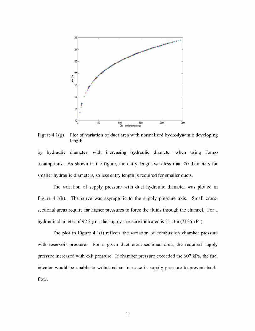
44
by hydraulic diameter, with increasing hydraulic diameter when using Fanno
assumptions. As shown in the figure, the entry length was less than 20 diameters for
smaller hydraulic diameters, so less entry length is required for smaller ducts.
The variation of supply pressure with duct hydraulic diameter was plotted in
Figure 4.1(h). The curve was asymptotic to the supply pressure axis. Small cross-
sectional areas require far higher pressures to force the fluids through the channel. For a
hydraulic diameter of 92.3 µm, the supply pressure indicated is 21 atm (2126 kPa).
The plot in Figure 4.1(i) reflects the variation of combustion chamber pressure
with reservoir pressure. For a given duct cross-sectional area, the required supply
pressure increased with exit pressure. If chamber pressure exceeded the 607 kPa, the fuel
injector would be unable to withstand an increase in supply pressure to prevent back-
flow.
Figure 4.1(g) Plot of variation of duct area with normalized hydrodynamic developing
length.
45
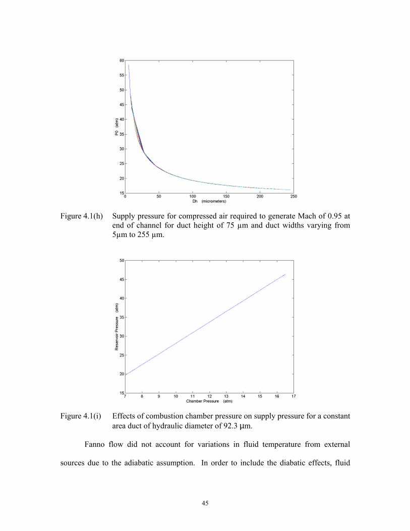
Figure 4.1(h) Supply pressure for compressed air required to generate Mach of 0.95 at
end of channel for duct height of 75 µm and duct widths varying from 5µm to 255 µm.
Figure 4.1(i) Effects of combustion chamber pressure on supply pressure for a constant
area duct of hydraulic diameter of 92.3 µm.
Fanno flow did not account for variations in fluid temperature from external
sources due to the adiabatic assumption. In order to include the diabatic effects, fluid

46
temperature was varied for a single duct size, as plotted in Figure 4.1(j). Variations in
volume flow rate and reservoir pressure with temperature were generated for a duct of
120 µm wide and 75µm high. The lower temperatures required an increased supply
pressure to generate a specified volume flow rate. The duct exit pressure was 709 kPa (7
atm), which, in the absence of a pressure gradient, corresponded to zero flow in the
figure. For a supply pressure of 21 atm (2126 kPa) and 14 atm (1417 kPa) at 600ºC, the
corresponding flow rates are 4.7 ml/s and 3.5 ml/s, respectively.
As shown in Figures 4.1(f) and 4.1(h), minimization of entry length and supply
pressure created conflicting design constraints. Entry length increased with increasing
channel size due to the slower boundary layer development. For broader channels, the
no-slip effect required longer lengths to become fully developed. Supply pressure
increased dramatically with decreasing channel size due to the increase in surface
Figure 4.1(j) Variation of exit volume flow rate from a duct of 5mm length with
supply pressure (P0) at entry temperatures ranging from room temperature to 600°C.
Increasing channel temperature

47
roughness to hydraulic diameter ratio. As this ratio increased, sensitivity to channel
surfaces increased. Another important consideration was the requirement of sufficient
volumetric flow rate in order to feed enough combustive gases into the secondary
combustion chamber to create the proper atmosphere for flame stability. Figure 4.1(k)
indicates the variation in volumetric flow rate as a function of channel size at elevated
room temperature (325K).
The design conflict could be reduced significantly by prioritizing the parameters
according to fabrication limitations. Fabrication constraints led to a reduced thickness for
Plate C, which contained the air swirlers on the surface, within the confines of out-of-
plane deflection limitations. The intolerance of the design to plate deflection was the
primary limitation on reservoir pressure. This matter will be further analyzed in Section
4.1.3. Ranges of hydraulic diameters corresponding to required parameters were
summarized in Table 4.1(a).
Figure 4.1(k) Volume flow rate variation with channel size at channel exit at 325K.

48
4.1.1.3 Rayleigh flow
To maximize heat transfer, the temperature (T0) of the fluid within the stagnation
reservoir was assumed to be 25°C and the exit temperature was 600°C, which was the
maximum design temperature of the prototype fuel injector. Using Equation 2.3.14, the
corresponding reservoir pressure (P0) was extracted using these conditions. The resulting
supply pressure was 1508 kPa (14.9 atm).
4.1.2 Fuel Supply Pressure
Simplification of the flow path and fluid properties was necessary for
approximation of the fuel supply pressure. Figure 4.1(l) shows the predefined points for
tracing pressure gradients in the fuel. In this section, the results of calculations using the
finalized fuel cross-section are presented.
Two different fuels were useful for flow and injection experiments with this
prototype: ethanol and kerosene. These fluids vary only slightly in their properties, as
indicated in Table 4.1(b), so ethanol was selected for all the remaining fuel calculations.
Table 4.1(a) Summary of feasible ranges of Dh for the corresponding contributions resulting from the calculations in the Modeling section.
Dh (mm) Controlling factors Le < 200 Le < 5.0 mm Po > 80 Po < 2025 kPa (20 atm)
Air flow rate > 140 Fuel flow rate = 0.13 mL/s With 60:1 air dilution

49
Since the fuel was atomized through the micro hole between States 2 and 3, it was
necessary to determine whether compressible or incompressible models were to be used
for fuel flow calculations. It is widely accepted that a compressible fluid with a Mach
number less than 0.3 may be modeled as incompressible (Munson, 1990). To determine
if fuel velocity was low enough to be considered incompressible, Equations 2.4.1 and
2.4.2 were used to determine the Mach number of the ethanol. The design fuel flow rate
at the exit of each nozzle (State 3) was 0.13 ml/s. The Mach numbers of the fuel at States
2 and 3 were 0.03 and 0.01, respectively. These values were the maximum fuel velocities
generated in the fuel injector in a channel length sized with the following dimensions:
length of 1 mm, height of 75 µm, and width of 50 µm. Since these Mach values were
less than 0.3, the incompressible fluid assumption was valid.
Figure 4.1(l) Drawing of a micro nozzle cross-section.
Table 4.1(b) Summary of fuel fluid properties. Fluid
Properties Ethanol Kerosene
Density (kg/m3) 789 800 Viscosity (Pa⋅s) 1.2 x 10⁻³ 1.6 x 10⁻³ Bulk modulus
(GPa) 0.902 -
1

50
Conservation of mass with constant density was used to estimate changes in flow
rate with variations in orifice size. Equations 2.4.3 and 2.4.4 were used to calculate the
pressure drop due to viscosity (∆Pµ) and energy effects (∆Pv), respectively. Table 4.1(c)
summarizes both types of contributions. The total pressure drop was 671 kPa, which
indicates the pressure required to accelerate the fluid from stagnation to the air swirl
chamber at the prescribed flow rate. Overestimation of the required pressure was made
to include safety factors where possible since these calculations were so simplified.
Thus, the negative values obtained for pressure changes from state 2 to 1 were neglected.
Since the injection pressure into the combustion chamber was assumed 101 kPa over the
combustion chamber pressure, the fuel reservoir pressure summed to 1381 kPa (200 psi).
Some intermediate parameters in the fuel nozzle are indicated in Table 4.1(d).
4.1.3 Fastener Separation Distance
Table 4.1(c) Pressure contributions at the paths between the locations indicated in Figure 4.1(l)
Paths ∆Pµ (kPa) ∆Pv (kPa) 3→2 251 267 2→1 Negative Negative 1→0 123 30
Total pressure loss (3→0) 671 kPa Pressure required for entrance into
combustion chamber 710 kPa
Total Fuel Reservoir pressure 1381 kPa
Table 4.1(d) Summary of flow conditions at the corresponding sites indicated in Figure 4.1(l).
Location Geometry Velocity (m/s) Flowrate (E-6 m3/s) 3 φhole = 110 µm 13.7 0.13 2 φhole = 75 µm 29.4 0.13
1 Four 50µm x 75µm channels
8.7 per channel 0.03 per channel
0 Reservoir 0 0

51
Eliminating out-of-plane deflection of the assembled plates by strategically
locating fasteners would assist in sealing the reservoirs. The distances between fasteners
were determined by initially considering the maximum distance between two fasteners
that would maintain acceptable deflections. The distances were then mapped onto the
nozzle pattern for orientation. Table 4.1(e) summarizes the material and physical
properties that were used for the calculations for each of the plates.
The distributed load, in force per unit length, was based on values that were
derived in the last two sections. The distributed load was the result of the pressure
differential across the plate. It was calculated by multiplying the pressure differential and
the width of the applied load. The width could have been chosen as a variety of different
values for modeling purposes. The most conservative case was the one that generated
larger loads. For these calculations, the chosen width was the working area of the
circular reservoir, which was 76.2 cm2. For each plate, the distributed load was
determined by finding the pressure differential between the sides of the plate and
multiplying that value times the working area. These values are indicated in the drawing
in Figure 4.1(m).
The reservoir and combustion chamber pressures in Figure 4.1(m) show that the
potential for back-flow of compressed air through the microhole existed. The maximum
pressures on Plate C were predicted to be higher on the air (top) side than the fuel
Table 4.1(e) Summary of material properties and dimensions for each plate in the assembly for properties at 600°C (Hoyt, 1954).
Material E (GPa) Thickness (mm) Poisson’s Ratio Plate A Inconel 600 180 1.0 0.31 Plate B Inconel 600 180 1.3 0.31 Plate C Nickel 201 170 1.3 0.30 Plate D Stainless
Steel 316 193 5.2 0.30

52
(bottom) side. These pressures reflect maximum flow rate conditions as determined in
Sections 4.1.1 and 4.1.2. Adjustment of the compressed air reservoir pressure to that of
the fuel reservoir, 1417 kPa, prevented the opportunity for back-flow while maximizing
the air flow rate.
Equations 2.5.1 and 2.5.2 were used to determine the maximum distance between
fasteners.
12
3bhI = 2.5.1
ymax = EI384
L4oq 2.5.2
The resulting fastener distance, L, determined the width shown in Figure 4.1(o).
Assuming a square plate portion, L is equal to b in Equation 2.5.1. Therefore combining
Equations 2.5.1 and 2.5.2 with the distributed loads indicated in Figure 4.1(n) and solving
for L resulted in the fastener distance for a given maximum deflection. Figure 4.1(o)
Figure 4.1(m) Summary of maximum pressures applied to each face and distributed load (qo) for deflection analysis for each plate in the assembly.
z y
x101 kPa
607 kPa
708 kPa
2126 kPa Changed to 1417 kPa
1417 kPa
qo = 3.2kN/m
qo = 108 kN/m
qo = 57.1 kN/m
qo = 97.3 kN/m Plate D
Plate C
Plate B
Plate A

53
indicates the distance between fasteners for each plate as a function deflection. The final
separation distance of 20 mm is indicated on the figure in this section.
Figure 4.1(o) indicates the minimal deflection of Plate D; however, the remaining
plates created unacceptable gaps under their loads, due primarily to plate thicknesses.
More realistic prediction of gaps in Figure 4.1(o) could be found by combining plates.
The assembled fuel injector with the plates laminated reinforced each plate to produce
Figure 4.1(n) Uniform distributed load applied to a clamped-clamped beam represents the pressure applied to the cross-section of the bolted plate. The distance between bolt centers is represented by L.
Figure 4.1(o) Resulting fastener distances for incremental deflection values for each plate individually.
Plate A
Plate D
Plate C
Plate B
qo
L

54
reduced deflections. As observed when comparing reservoir pressures in Figure 4.1.n,
Plates A, B, and C would deflect to form a three-dimensional convex geometry and,
similarly, Plate D would form a 3-D concave geometry. Plates A, B, and C were
combined as a single PlateABC for modeling purposes. PlateABC was considered 3.25 mm
thick with material properties of Inconel 600. This laminated single plate was a realistic
simplification since the plates were designed to be tightly clamped together at many
points. The pressure differentials between the fuel reservoir and the two external
pressures located outside of Plates A and D as shown in Figure 4.1(m) were used. The
resulting relation between the deflection of the two plates and the bolt distance are shown
in Figure 4.1(p). The maximum deflection values indicated at the two points of
intersection between the curves and 20mm fastener distance are 1 µm and 2.3µm for
Plate D and for Plate ABC, respectively.
Figure 4.1(p) Deflection values of assembly using air reservoir limited to 14 atm and the thin plates reinforced with Plate C, with length equal to 20 mm.
PlateD PlateABC

55
The curves in Figure 4.1(p) reflected improved reinforcement of the plates
through assembly. In Figure 4.1(p), the 20 mm distance resulted in combined maximum
gaps between mating plates of more than 3 µm when subjected to previously defined
maximum operation pressures. These gaps were far too large for sealing purposes.
Therefore, limitations on reservoir pressures may be imposed during testing for proper
function of the fuel injector.
To verify the deflection values presented above, the secondary model using the
Equations 2.5.3. and 2.5.4. This model was applied to two different plate sizes. Case 1
modeled the deflection of the reservoir assuming no internal fasteners. It was a circular
geometry of radius 32 mm with a uniformly distributed load and it was constrained
(clamped) in the circular pattern the model describes. The second case was to assume the
four fasteners that were located about each swirler behaved like a circular clamping
perimeter with radius of 10 mm, which was half the fastener distance. The results of
these calculations are listed in Table 4.1(f). Due to the equal maximum design pressures
on both sides of Plate C, the deflection would be zero.
Table 4.1(f) Deflection results for maximum applied load for the circular plate. Case 1 Case 2 Deflection
(µm) Bending
stress (MPa) Deflection
(µm) Bending
stress
Yield strength at
600ºC (MPa)
Plate A 100 78 0.95 7.6 330
Plate B 356 349 3.4 34 330
Plate C 0 0 0 0 70
Plate D 8.6 37 0.08 3.7 207
Plate ABC 20 - 0.19 - - Table 4.1(f) indicates the vast difference in deflection values depending on the
circular plate as defined by the fasteners. Case 1 significantly overestimates the

56
deflection since it is assumed there are no fasteners surrounding the swirlers within the
reservoirs. Case 2 slightly underestimates the deflection since there are only four
fasteners, not a full perimeter of them. The 3 µm deflection determined in the analysis
presented above is within the range indicated by this model.
4.1.4 Thermal Expansion of Plates
There were two areas of concern when considering the effects of thermal
expansion. Expansion of plate thickness may exceed expanded bolt length, resulting in
plastic deformation of the bolt during heating with insufficient clamping when cooled.
Additionally, deformation in the xy plane, as indicated in Figure 4.1(m), due to thermal
expansion could cause buckling if the fasteners were clamped to another device, such as a
combustion chamber. Further investigation of both types of expansion was necessary.
For thermal expansion in the z-direction, a preliminary calculation using the
thermal conductivity of the metal plates without fluids flowing through the reservoirs
revealed that the temperature difference between Plates A and D was 4°C, with a
temperature of 600°C for Plate A. This temperature difference was considered negligible
and 600ºC was applied to all four plates. Elevated temperatures cause expansion in
metals, according to Equation 4.1.1.
∆Lz = δt⋅L·∆T 4.1.1
where ∆Lz is the change in plate thickness, δt is the linear coefficient of thermal
expansion, L is the plate thickness, and ∆T is the change in temperature, with room
temperature as the reference. The coefficient of thermal expansion is material specific
and can be temperature dependent. Values of coefficient of thermal expansion were

57
chosen with the applied temperature range. These parameters and expansion results for
the design temperature of 600°C are shown in Table 4.1(g).
The bolts expand 44.5 µm more than the accumulated plate expansion. This
expansion difference could create spaces for leakage if not addressed. In order to
maintain tension on each bolt at elevated temperatures, a lock washer was added. Further
discussion on the specifications of hardware used for clamping the fuel injector is found
in Section 4.2.
There are two different effects that made thermal expansion in the xy plane
unworthy of further investigation. First, thermal expansion would be uniform due to the
high conductivity of each plate, which would result in subsequent uniformity of
expansion upon exposure to elevated temperatures. Additionally, the fastener holes were
fabricated significantly larger than the shaft diameter. Therefore, relative motion of the
plates, caused by differences in thermal expansion coefficients, would eliminate
buckling. Isotropic expansion effects tend to cause dimensional changes symmetric
about the centroid of the piece, with increasing effects as distance from the centroid
increases. Thus, relative plate motion would have negligible effects on critically
alignmed features since they were located close to the centroid of the fuel injector.
4.1.5 Deflection of Microchannel Walls
The original design of the air swirler included straighteners, which split the
Table 4.1(g) Thermal expansion of the plates and bolts at 600ºC. Component Material δt (µm/m·K) L (mm) ∆L600 (µm) Plates A, B Inconel 600 13.3 2 22.6
Plate C Nickel 201 13.3 1.25 14.1 Plate D SS 316 18 5.2 79.4
Total for all plates
138.7
Bolts SS 316 18 12 183.2

58
120 µm wide channel into four microchannels. The prototype was modified to remove
the microchannels, but a brief analysis was necessary to determine the strength of these
walls when subjected to fluid flow. This analysis determined if the material strength of
the thin wall would be adequate if a distributed force acted on it.
The dimensions of each channel wall were 16 µm wide, 75 µm high, and 3500
µm long. These fins had a length aspect ratio of over 45. To simplify the effects of the
fluid inside the reservoir, two times the original reservoir pressure (2126 kPa) was used
as the applied pressure for modeling. The doubling of the reservoir pressure was realistic
since at any moment there may be a positive pressure of that magnitude applied to one
side of the wall and a negative pressure of that magnitude applied to the opposite side of
the same wall. This value was translated into the distributed load by multiplying it by the
fin height. A cantilever beam was used to model the fin since the top of the walls were
not designed to adhere to the cover plate (Plate B). It was assumed the cantilever beam
would provide a more conservative estimate of fin deflection than a clamped-clamped
beam. The dimensions of the beam in the equations correlated to fin geometry according
to the drawings in Figure 4.1(q). Equations 2.6.1 through 2.6.3 were used for these
calculations. The moment of inertia was determined by using the full length of the fin as
the base. The results of these calculations are listed in Table 4.1(h).
Comparing the applied stress on the fin to the yield strength of the electroplated
nickel, 323 MPa (Sharpe, LaVan, & Edwards, 1997), these calculations predicted fin
survival in reservoirs at the maximum design pressure.

59
These results indicated the ability of the fins to avoid yielding in the high-
pressure air channels. There was no indication whether the adhesive strength of the
electroplated nickel to the substrate may be a limiting factor in fin survival. There was
also the clamping force of the capping plate to consider. This force could assist in
reducing deflection or it could cause buckling of the fin.
4.1.6 Conclusions
Compressible fluids calculations along with plate deflection considerations
revealed competing constraints in sizing between channel dimensions and the supply
pressure for the air; however, a compromise was found to reduce supply pressure.
Dilution quantities needed for mixing air and fuel with a ratio of 60:1 was not
maintained, since only 27:1 was possible with the maximum design air supply pressure.
However, a complementary air reservoir will compensate for the reduced air inside the
combustion chamber.
Figure 4.1(q) Simplification from fin as mounted on the substrate (left) a constrained cantilevered beam (right).
Table 4.1(h) Results of applied load on each fin. Reservoir pressure (kPa) M (N⋅m) σapp (MPa)
2126 4.2 x 10⁻⁵ 222
75 µm
3500 µm
16µm
b
L
h

60
The finalized channel dimensions were determined from these calculations and
are summarized in Table 4.1(i). To preserve the micrometer scale of the nozzles, swirler
length minimization was a primary priority. A 92.3 µm hydraulic diameter would yield
an air channel length of 2 mm. The channel length was eventually altered from the 2 mm
to 5 mm since the prototype had more space to allow for longer channels.
The next section in this chapter reveals the details of the metal fuel injector
design. The design process was iterative, using calculations, design criteria, and
fabrication limitations to converge on a configuration feasible for fabrication and a robust
assembly.
4.2 Prototype Design
For the design to be appropriate, the fuel injector must function according to the
device specifications that were detailed in Section 1.3. An effective means of moving
separate fluids through their own swirl channels and swirl chamber, forcing fuel into a
microhole, and then spraying the air/ fuel mixture into the combustion chamber had to be
determined for a micro nozzle.
Each micro nozzle was composed of a swirler mounted on a substrate at each end
of a conically-shaped microhole, which passed through the substrate as indicated in
Figure 4.2(a). A swirler was composed of four swirl channels, which tangentially fed
fluids into a cylindrically-shaped chamber. This chamber was designed to induce swirl in
Table 4.1(i) Summary of final dimensions and resulting parameters as calculated. Air channel:
height/ width/
Dh
Fuel channel height/ width/
Dh
Maximum air and fuel
supply pressure
Maximum air flow rate
Maximum fastener distance/
Maximum gap
generated
75 µm/ 120 µm/ 92.3 µm
75 µm/ 50 µm/ 60 µm
1417 kPa 3.5 ml/s 20 mm 3.2 µm

61
the fluids. A three-dimensional view of an individual swirler is shown in Figure 4.2(b).
Air swirlers were located at the 100 µm end of the orifice, while fuel swirlers were
located at the 50 µm end.
The design of the prototype required eliminating preconceived ideas, focusing on
device function, and developing creative solutions to packaging. The calculations in
Section 4.1 indicate the small dimensions of the swirler channels. The swirl chambers
were required to be scaled with the channels similar to the image in Figure 4.2(b), which
would result in swirl chamber diameters on the order 102. Moving the fluids through the
channels and microhole into the combustion chamber required the channels to be capped.
Figure 4.2(a) Drawing of cross-section of a single nozzle. Note the size difference between the air and fuel swirlers.
Figure 4.2(b) Three-dimensional rendering of a generalized swirler.
Air swirlers
Plate C
Fuel swirlers
Conical micro hole
Swirler channels
Swirl chamber
Atomizing microhole

62
The caps required a hole with a maximum size equal to the swirl chamber diameter for
prevention of leakage. Alignment of these small holes over the center of each swirl
chamber was necessary to prevent interference of the induced vortical profile of the
exiting fluids.
Separation of the fluids to prevent premature mixing was also required. Attaching
the fuel and air swirlers on each side of a thin plate was beneficial for minimizing the
path length between the two swirl chambers and, again, preserving the vorticity in the
fuel for improved mixing with the air. In order to supply the channels with the fluids, a
submersion technique was adopted. Creating reservoirs of each fluid on the
corresponding side of the plate allowed control of fluid velocity through the nozzle by
controlling supply pressure. The reservoirs were defined and contained by the same
plates that capped the swirl channels. Additionally, the reservoirs allowed multiple
nozzles to be added to the plate since many swirlers could be submerged in the same
reservoir as easily as a single swirler. The number of nozzles added was limited by
swirler size and fabrication methods. The elevated pressures of the supply air and fuel
required plate clamping devices along with leakage prevention. The air and fuel were
supplied by fittings, the number of which could be far fewer than the number of micro
nozzles. The connectors could have been located at various positions around the plates,
but it was considered easier to attach them on the bottom side of the prototype since this
would reduce interference of the supply lines with other features of the combustion
chamber. Passages within the prototype were needed to isolate and direct the fluids to the
appropriate reservoirs. Another reservoir was added above the high pressure air reservoir
to provide extra air needed for controlled dilution of the combustive mixture at locations

63
adjacent to the mixture exit site. Supply lines and passages for this added reservoir were
also required. Fabrication methods were balanced with nozzle function and design. A
combination of precision machining, traditional machining, and micromachining were
determined necessary for prototype fabrication.
4.2.1 Swirler Dimensions
The swirler design started with the microhole size and shape and the results of the
fluidic calculations. The swirl chamber diameters were estimated by taking into account
the amount of space needed to allow fluid to enter the swirl chamber tangentially from
four points and to establish swirl before injection. Channel dimensions determined in
Section 4.1 are summarized in Table 4.2(a) along with the finalized design dimensions of
both air and fuel swirler chambers. The geometry of the conically-shaped microhole is
reflected in the two microhole diameters listed in the table.
Early in the project, the developing entry length of each air channel was reduced
by dividing the 120 µm wide passage into four microchannels. Each microchannel width
was calculated by determining the widths of the dividing walls that could survive
fabrication and operating stresses. The results of Section 4.1.6 indicated a 16 µm wall
thickness does not physically yield in the turbulent fluid environment. As a result, four
microchannels 18 µm wide were created with three 3.5 mm long fins. Figure 4.2(c)
indicates the layout of the four micro channels in the air swirler. This design is referred
to as Channel Design I. Channel Design II evolved after calculations indicated that
Table 4.2(a) Swirler dimensions
Design
Microhole Diameter
Swirl Chamber Diameter Channel Width Channel
Height Channel Length
Fuel Side 50 µm 200 µm 50 µm 75 µm 1000 µm Air Side 100 µm 600 µm 120 µm 75 µm 5000 µm

64
excessive pressures were required to force the fluid through the long microchannels. The
microchannels were eliminated from the design, leaving the 120 µm wide channels for
supplying air to the swirl chamber. Channel Design II is the air swirler design
generically referred in the remainder of this document.
4.2.2 Plates
The plates were required to house the nozzles, cap the swirler channels, and
accommodate fluid delivery. Fluid delivery required high pressure air, lower pressure
air, and fuel transport from the external sources to corresponding reservoirs. The
delivery system also included the supporting channels that eliminated premature mixing
and facilitated prescribed mixing and injection into the combustion chamber.
Figure 4.2.c Illustration of a microfabricated air swirler consisting of four 18 µm
wide microchannels created by three 16 µm wide electroplated nickel fins on each leg. The high-pressure fluid enters the swirler from beyond the microchannels, travels through the straighteners and into the swirl chamber, and exits through the hole in the center of the swirl chamber (not indicated in the drawing) in a direction perpendicular to the swirler plane.
φ 600 µm swirl chamber
120 µm
16 µm x 3.5 mm long fins

65
4.2.2.1 Reservoirs
Reservoirs were used to transport specific fluids to the prescribed locations for
proper function of the nozzles. Flooding the volumes that surround the array of swirlers
with pressurized fluids maintained uniform pressure to the swirlers. Additionally,
reservoirs serve to reduce the number of connection sites for supply lines for each fluid.
Decreasing the need for multiple connectors per fluid conserves the compact size of the
array of micro-injectors.
Alternatives to reservoirs would have required interfacing micrometer-scaled
features with 1.5 cm diameter fluid connections. Without reservoirs multiple fluid
connections for each swirler along with logistical problems in interfacing with the
combustion chamber would have added much complexity to the design of multiple
nozzles.
Three reservoirs were created for the three fluids. The reservoirs were isolated
and sealed by stacked metal plates, as indicated in the cross-sectional view of the metal
prototype shown in Figure 4.2(d). Reservoir 1 contained and supplied supplementary air
for dilution control of the injected mixture after entry into the combustion chamber. The
air in Reservoir 1 was held at pressures just above the combustion chamber pressure since
it was not required to flow through micro channels. A seal was needed to isolate the air
in the reservoir to prevent air from leaking into the air/fuel mixture before entering the
combustion chamber. A separate air supply was channeled to Reservoir 2 at pressures
which depended on fuel flow rate in order to meet prescribed dilution quantities of the
injected mixture. Reservoir 3 housed the pressurized fuel.

66
The low pressure air was injected directly into the combustion chamber at
locations adjacent to and surrounding the air/fuel mixture injection orifice through Plate
A, as indicated in Figure 4.2(e). The injection holes were 1mm in diameter, which was
large enough to machine easily, yet small enough to provide a fine distribution of air
around the mixture exit site. The cylinder needed to seal Reservoir 1, as indicated in
Figures 4.2(e), was 5 mm in outer diameter with 1 mm inner diameter.
For flow rate adjustment, the reservoir pressures were controlled externally with
supply line pressure. A piezoelectric actuator was originally devised to pump fuel
Figure 4.2(d) Schematic of the cross-section of the prototype assembly with a single
nozzle, capping plates, and reservoirs.
Figure 4.2(e) Schematic view of the localized area surrounding each air/fuel mixture
exit orifice on Plate A, as viewed from the side of Plate A that interfaces with Plate B.
Reservoir 1
Reservoir 2
Reservoir 3
Plate A
Reservoir seal
Plate B
Air Swirler
Plate C
Fuel Swirler
Plate D
Supplementary air injection holes
Air/fuel mixture exit hole
Cylinder for sealing mixture fluids from
supplementary air

67
through the fuel swirlers; thereby controlling the frequency of injection. This feature
could be integrated into the next generation prototype.
4.2.2.2 Dimensions
The design of the reservoirs and the need to seal them led to the laminated plate
assembly shown in Figure 4.2(d). The metal plates provide strong, robust containment
for the corrosive, pressurized fluids. The frontal area and thickness of each plate
depended on many factors: maximum reservoir pressure requirements, feature sizes,
fabrication limitations, mechanical properties of plate materials, and fastener sizes.
Each metal plate face was sized to allow space for the features, but within the
confines of fabrication equipment compatibility. The face area of each square plate was
10 cm x 10 cm, which was small enough to fit in most of the fabrication equipment
normally used to hold 100 mm circular silicon wafers. Figure 4.2(f) indicates a plate
with the corners chamfered in order to accommodate the jig for precision machining,
which is discussed in section 4.3.
Since the four plates were subjected to high pressures within the reservoirs,
maximizing the thickness of each plate increased the stiffness of the assembly according
Figure 4.2(f) Drawing of plate face area.

68
to results found in Section 4.1.3. The thickness of Plates A, B, and C were minimized in
order to decrease travel distance of air/fuel mixture within the limitations imposed by
plate deflection. The thickness of Plate D was maximized within limits of fastener shaft
length. A balance between stiffness and other parameters resulted in a compromise in
final thickness for each plate. The results are summarized in Table 4.2(b).
The thickness of Plate A is 2 mm since 1 mm of material was removed to create
the low-pressure air reservoir, as discussed in Section 4.2.2.3.
Plate B was minimized in thickness within the limitations of dimensional
stability. Plates generally have internal stresses which can cause deflection if they are too
thin. The limit to plate thickness for the Inconel 600 and Nickel 201 plates was
determined to be approximately 1.5 mm. This value varies by ±0.5 mm depending on the
origin of the metal and the skill of the machinist performing the grinding.
The thickness of Plate C was dictated by the aspect ratio of the microholes,
microhole drilling method, and capabilities of the machinist. The diameter of the
microhole was originally 50 µm. EDM plunge drilling was the method chosen for
drilling a conically-shaped microhole. Aspect ratio limitations for EDM plunge drilling
were 17 for the experienced operator, Dean Jorgensen (personal communication, June
1999), with a nickel substrate, which is impressive when compared to conventional
length to diameter ratios of 7 for mechanical drilling. As the diameter of the microhole
decreased, the plate thickness was required to decrease by a multiple of 17. The plate
Table 4.2(b) Summary of final plate dimensions. Plate A B C D
Thickness (mm)
2.00 ± 0.05 1.25 ± 0.05 1.250 ± 0.025 5.20 ± 0.05

69
was required be thick enough to maintain stiffness, flatness, and dimensional stability, yet
thin enough to drill the microhole. A thickness of 1.25 mm with a minimum diameter of
75 µm was the most acceptable compromise that was compatible with the drilling process
for Plate C. A tolerance of ±25 µm was imposed on the plate thickness, since variations
would affect microhole aspect ratio and drilling results.
The face size and thickness of the plates became more important as fabrication
methods were determined. The main difficulty encountered with fabricating metal plates
was excessive weight. Some of the microfabrication equipment use automated wafer
transport devices, which were designed for the standard 10 gram silicon substrates. The
metal plates described in this section easily exceeded this limit. The plate area also posed
problems for various precision machining and microfabrication jigs since it strayed from
the standard 100 mm circular silicon wafer size.
4.2.3 Fluid Passages and Connectors
External connections and internal paths were required to direct fluids through the
prototype while avoiding leakage and premature mixing. The fluid connections to the
device were located on the bottom side of the prototype in order to minimize disorder of
supply tubing and avoid interference with the combustion chamber. Internal passages
were required to isolate the fluids as they traveled to their respective reservoirs.
Connectors for the external fluid supply lines were five compression fittings
attached to the bottom side of Plate D, shown in Figure 4.2(g). One fitting for the fuel
lines and two fittings of each air pressure line were connected. The number of air inlets
were doubled since pressure distribution of the compressible fluids was a concern early in
the project. Increasing the number of inlets ensured a uniform pressure distribution of air

70
inside Reservoirs 1 and 2. The locations of passage and connection sites are discussed in
Section 4.2.8.
Specifications for the compression fittings are summarized in Appendix A. The
fittings were attached by tapping Plate D at the entry sites and screwing in the
compression fittings. Three and a half threads held the tapped portion of Plate D for each
compression fitting. Strength was enhanced by welding the base of each connector at the
plate interface. Since the fluids were designed to travel through the joint at a maximum
pressure of 1417 kPa, the weld also sealed the joint to prevent fluid leakage and improve
strength.
Internal passages were needed to move high pressure air past Reservoir 3 to reach
Reservoir 2. Additionally, low pressure air had to pass through Reservoirs 3 and 2 to
reach Reservoir 1. In order to eliminate leakage between the fluids in the passages and
the reservoirs, annular seals between the passages and around the passage holes were
machined in the plates, as indicated in figure 4.2(h). Plate D entered Reservoir 3 without
bypassing another reservoir. The seals were required to align with the corresponding
Figure 4.2(g) The back side of Plate D. The five compression fittings are situated to
connect with fluid supply lines.

71
fluid hole within a generous tolerance that was coarse compared to alignment
requirements of other features on the plates.
4.2.4 Plate Fasteners
A fastening mechanism was needed to seal the reservoirs and maintain alignment
between the plates. In choosing the fastening method, plate condition and fastening
effects were important. Since sealing involved plate flatness and surface finish, these
parameters had to be preserved. Fastening strength between the plates needed to be
strong enough to withstand the separating tendencies of the maximum reservoir pressures
without deflection. Bolts secured with nuts were fastening mechanisms used for this
prototype.
Bolting the four plates together was a good choice since the fastening strength
could be ensured to meet requirements. There were no modifications, such as heating or
Figure 4.2(h) Schematic indicating leakage prevention seals located between the reservoirs and internal passages. The low pressure air bypassed two reservoirs before entering Reservoir 1 and the high pressure air bypassed the fuel reservoir before entering Reservoir 2.
Plate A Plate B Plate C Plate D
Reservoir 1
Reservoir 2
Reservoir 3
Low pressure air
passage
High pressure air
passage
Fluid passage seals

72
machining, to the plates during assembly which could compromise plate strength or ruin
features. Disadvantages of using bolts included additional efforts to design appropriate
sealing between the plates. Reduction in work area, such as reservoir volume and sites
for more swirlers, resulted from designation of space for the bolt shafts and seals, as
discussed in Sections 4.2.5 and 4.2.8.
Ultrasonic welding was a fastening alternative considered for the prototype. This
method uses vibration and pressure to weld the two plates at their points of contact. A
benefit to this method was its sealing capabilities. Ultrasonic welding was rejected since
it introduces severe vibration to the weld site. The vibration would have deformed,
damaged, or delaminated the smaller microfabricated features.
Bolt size was determined by balancing bolt strength, shaft diameter, and shaft
length. Bolt strength depended on the material used and shaft diameter. Bolt shaft length
was dictated by shaft diameter, since length to diameter ratio is standardized in order to
reduce the possibility of buckling. Shaft diameter was minimized due to congestion of
the other features within the limitations of bolt strength. Additionally, shaft length was
required to be long enough to accommodate required plate, nut, and lock washer
thickness.
Each plate was stacked along the fastener shaft, according to the image in Figure
4.2.b. The fasteners were 316 stainless steel M2 x 12 bolts, meaning a 2 mm shaft
diameter and 12 mm shaft length. This was the longest standard length for the M2 bolt.
According to Figure 4.2(i), the bolt length was shorter than the required length to
properly bolt the stacked components by 0.2 mm. This shortage was acceptable since it
excluded half of a thread rotation, out of possible four, at the nut/bolt interface.

73
4.2.5 Sealing
Sealing was necessary to contain the fluid within each reservoir while it was
forced through swirler channels. Leakage through various sites could contaminate the
reservoirs, undermine the function of the swirlers, and reduce stagnation pressure in an
unpredictable manner. Figure 4.2(j) shows a potential leakage path for a fastener hole.
Fastener sites within the reservoirs were sealed by annular leakage seals located around
the drilled holes, similar to the sealing for fluid passages discussed in Section 4.2.3.
These cylinders compress against the mating plates at the fastener and fluid passage
orifice sites.
The reservoirs, swirler channels, fluid passages, and fastener sites were capped
and sealed through flatness and smoothness of the mating plates and parts. This
procedure required two flat, smooth surfaces joined under compression to prevent
leakage. Seals created by plate flatness demanded flat, smooth surfaces of mating parts.
Figure 4.2(i) Cross-sectional drawing of plates stacked on one bolt including lock washer and nut. The thickness of Plate C is shown as 1.4 mm since the actual thickness is 1.25mm with 0.075mm high microfabricated components added to each face of Plate C.
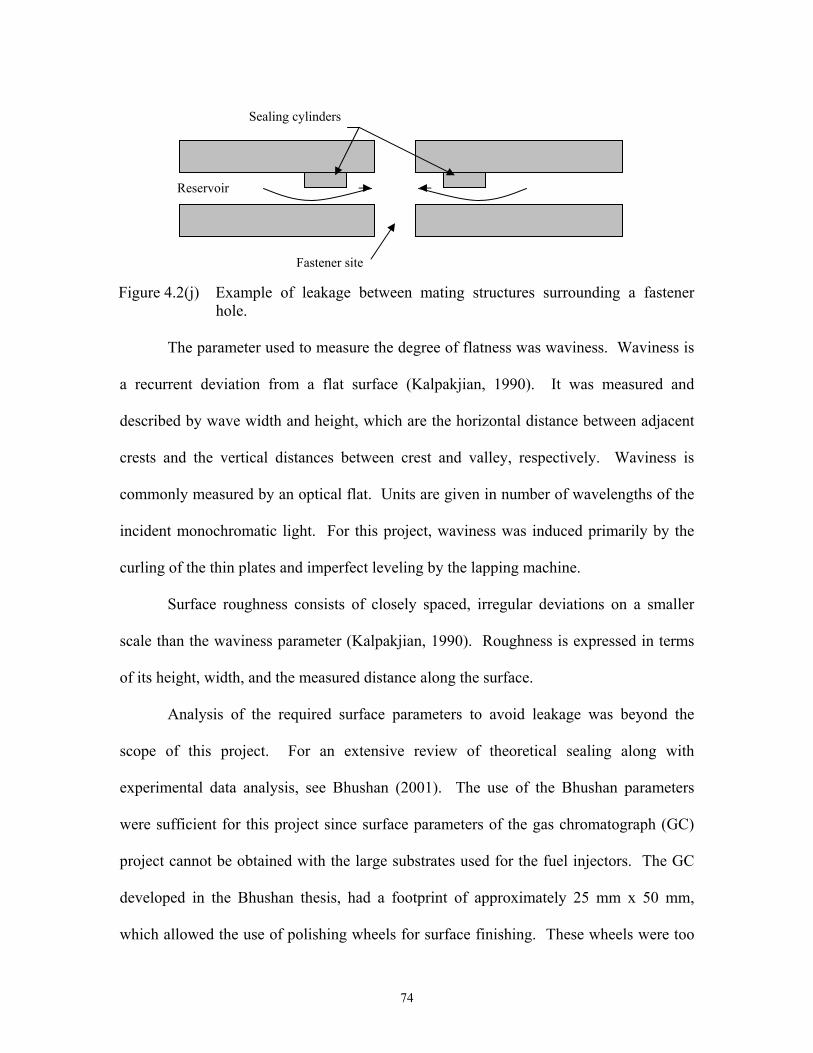
74
The parameter used to measure the degree of flatness was waviness. Waviness is
a recurrent deviation from a flat surface (Kalpakjian, 1990). It was measured and
described by wave width and height, which are the horizontal distance between adjacent
crests and the vertical distances between crest and valley, respectively. Waviness is
commonly measured by an optical flat. Units are given in number of wavelengths of the
incident monochromatic light. For this project, waviness was induced primarily by the
curling of the thin plates and imperfect leveling by the lapping machine.
Surface roughness consists of closely spaced, irregular deviations on a smaller
scale than the waviness parameter (Kalpakjian, 1990). Roughness is expressed in terms
of its height, width, and the measured distance along the surface.
Analysis of the required surface parameters to avoid leakage was beyond the
scope of this project. For an extensive review of theoretical sealing along with
experimental data analysis, see Bhushan (2001). The use of the Bhushan parameters
were sufficient for this project since surface parameters of the gas chromatograph (GC)
project cannot be obtained with the large substrates used for the fuel injectors. The GC
developed in the Bhushan thesis, had a footprint of approximately 25 mm x 50 mm,
which allowed the use of polishing wheels for surface finishing. These wheels were too
Figure 4.2(j) Example of leakage between mating structures surrounding a fastener hole.
Sealing cylinders
Reservoir
Fastener site
75
small for the fuel injector substrate size. Additionally, Bhushan did not include waviness,
which was important with a broader substrate. Finally, the GC internal pressure
requirements were maximum 709 kPa, compared to the maximum reservoir pressures of
1418 kPa for the fuel injector. The elevated pressure would require improved surface
requirements to contain the fluids. The Bhushan values were used as guidelines to fuel
injector prototype parameters since even those finishes could not be obtained with the
same surface finishing options available for the fuel injector plates. Specifications and
results of surface finish are presented in Section 4.3.1.4.
Leakage through the fastener sites was detected with a submergence test since no
fluids were expected to flow out of these holes. Of course, similar leakage could also
occur over the swirlers, circumventing the channels, as shown in Figure 4.2(j). This
problem would be difficult to detect since the fluid would continue to flow through the
micro hole as anticipated. Particle image velocimetry (PIV) could be used to compare
experimental results with expected injection profile since expected swirl would not be
generated with this type of leakage.
Gaskets were considered as an alternative for sealing. It was decided the gasket
thickness and the required deformation of the gasket material during assembly would
interfere with reservoir volumes.
Interlocking mechanical seals were not used since design simplicity was a
priority. It was determined that the flat plates would be less complicated than mechanical
seals since the bond strength of electroplated structures to the plate was unknown.
Adhesive strength to the substrate was a parameter vital to the success of mechanical
seals since the mating materials are exposed to various lateral forces.

76
4.2.6 Alignment
The location of the plates relative to each other in the assembly required
procedures for alignment. The air/fuel mixture exiting the nozzle passed from the air
swirler and microhole through Plates B and A before injecting into the combustion
chamber, as shown in Figure 4.2(k). Subsequent studies on the completed prototype
would involve fluid profile characterization. Interference with the exiting mixture caused
by misalignment between Plates A, B, and C could result in misrepresented experimental
data. Additionally, the connection sites and fluid passages must be aligned in order to
avoid leakage. The critical plate-to-plate alignment involved clearing the path for
mixture injection without disrupting flow from the microhole to through Plate A.
Alignment pins were used in coordination with precision-drilled holes in each
plate to achieve the prescribed alignment between the plates. Alignment of each plate
relative to the others was obtained by inserting the pins in the same corresponding hole as
those in the other plates, as indicated for Plate A in Figure 4.2(l). Once aligned, the
plates were then fastened with the bolts and nuts. The alignment holes were needed for
alignment only during assembly of the fuel injector, after which they served the purpose
of fastener sites for connection of the fuel injector to the combustion chamber. Design
parameters were not necessary for this secondary purpose of the alignment holes, since
the fuel injector was expected to be retrofitted to the combustion chamber.
Proper plate alignment involved consideration of tolerances on size, location, and
relative orientation of alignment and atomizing holes. In order to achieve uniform flow
results from the exiting orifices, total error of less than ±50 µm was available for the
misalignment between any two plates.

77
Tolerances based on machining capabilities were accumulated for the alignment
holes and microhole drilling, as summarized in Table 4.2(c). Alignment holes were
mechanically drilled, while the microholes were electrodischarge machined (EDM), as
discussed in Section 4.3.
Figure 4.2(k) Schematic of the cross-section a single nozzle assembly with capping plates and reservoirs. The center line of the microhole, fuel swirler, air swirler, reservoir seal and each plate must be aligned relative to each other.
Figure 4.2(l) Photograph of Plate A as viewed from the side in contact with Plate B. The alignment holes are indicated.
Alignment holes
Alignment holes

78
Tolerances of the alignment holes were determined by allocation of total error
available between plates and machining tolerances. The originating feature was the
diameter of the alignment pin. Stainless steel dowels, which were machined to the
accuracy indicated in Table 4.2(d), were used for the alignment pins. The resulting
tolerances placed on the diameter of the alignment holes are indicated in Table 4.2(d),
while the tolerance indicated in Table 4.2(c) was used to located the alignment hole
positions. It is important to remember that the x-y positional error combined into a larger
radial error.
EDM drilling locations were oriented to a datum created for the previously drilled
alignment holes. The precision on EDM hole diameter was determined by the skills of
the EDM machinist. The critical tolerance feature was the relative distance between the
microholes. The error involved with relative location of these holes was ±8 µm. Once
the first microhole was located against a datum, the other microholes were located with
high precision. When comparing the air/fuel exit orifices in Plates A and B to the
microhole centers, a maximum error of 160 µm was calculated. Though this error is
outside of the ±50 µm total error for allocation, it is an error of 16% when viewed
through the 1 mm exiting orifice. This error was acceptable to the design.
Table 4.2(c) Tolerance of drilling capabilities Traditional
drilling EDM microhole
drilling X/Y translation ± 13 µm ± 10 µm
Diameter ± 13 µm ± 7 µm
Table 4.2(d) Resulting tolerance allocation for mating dowels and alignment holes
Feature Diameter Dowel size 3175µm +5, -0 µm
Alignment hole size 3223 µm ±25.4 µm
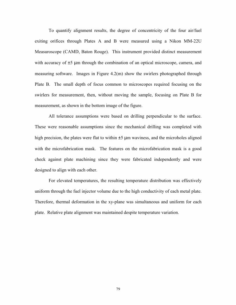
79
To quantify alignment results, the degree of concentricity of the four air/fuel
exiting orifices through Plates A and B were measured using a Nikon MM-22U
Measuroscope (CAMD, Baton Rouge). This instrument provided distinct measurement
with accuracy of ±5 µm through the combination of an optical microscope, camera, and
measuring software. Images in Figure 4.2(m) show the swirlers photographed through
Plate B. The small depth of focus common to microscopes required focusing on the
swirlers for measurement, then, without moving the sample, focusing on Plate B for
measurement, as shown in the bottom image of the figure.
All tolerance assumptions were based on drilling perpendicular to the surface.
These were reasonable assumptions since the mechanical drilling was completed with
high precision, the plates were flat to within ±5 µm waviness, and the microholes aligned
with the microfabrication mask. The features on the microfabrication mask is a good
check against plate machining since they were fabricated independently and were
designed to align with each other.
For elevated temperatures, the resulting temperature distribution was effectively
uniform through the fuel injector volume due to the high conductivity of each metal plate.
Therefore, thermal deformation in the xy-plane was simultaneous and uniform for each
plate. Relative plate alignment was maintained despite temperature variation.

80
4.2.7 Feature Layout
The nozzles, fluid passages, and fastener sites were located according to space
available within the limitations imposed by fabrication. Consideration of fabrication
techniques was vitally important in determining feature layout. Figure 4.2(n) 4.2(q) the
features and their relative locations on Plate A. The shop drawings in Appendix B
indicate the exact locations of the features.
Figure 4.2(m) Optical photographs of alignment each air swirler on Plate C are
shown in the top four images with the corresponding 1 mm diameter air/fuel mixture exit orifice in Plate B focused in the bottom image.
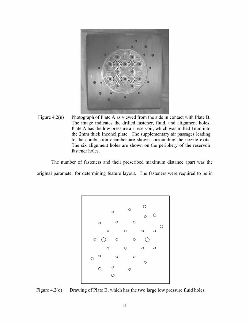
81
The number of fasteners and their prescribed maximum distance apart was the
original parameter for determining feature layout. The fasteners were required to be in
Figure 4.2(n) Photograph of Plate A as viewed from the side in contact with Plate B.
The image indicates the drilled fastener, fluid, and alignment holes. Plate A has the low pressure air reservoir, which was milled 1mm into the 2mm thick Inconel plate. The supplementary air passages leading to the combustion chamber are shown surrounding the nozzle exits. The six alignment holes are shown on the periphery of the reservoir fastener holes.
Figure 4.2(o) Drawing of Plate B, which has the two large low pressure fluid holes.

82
the same locations on all the plates and to be maximum 20 mm apart on center to
minimize plate deflection due to reservoir pressure. Fasteners were needed to surround
each swirler to reduce the possibility of fluid leakage between the swirler and cap plates.
Four fasteners in a diamond pattern surrounded each swirler, as shown in Figure 4.2(p).
To seal the outer edges of the reservoir, fasteners and their seals were needed
outside of the reservoir diameter, yet within the 80 mm working diameter imposed by
microfabrication mask work areas. This parameter resulted in the reservoir diameter of
64 mm.
It was estimated that maximizing the reservoir volume within the prescribed
diameter would allow easy maintenance of reservoir pressure uniformity. Four nozzles
were determined sufficient for flow analysis and would leave adequate reservoir volume.
The air swirlers were the largest nozzle features, which limited how closely the
fasteners could be positioned to the nozzles. The nozzles were centered in the reservoir
and positioned closely in order to share fasteners, as indicated in Figure 4.2(p).
Figure 4.2(p) The images show features for both sides of Plate C. The air and fuel swirlers are shown on the corresponding side of the plate. The air and fuel reservoirs are indicated by the largest diameter circle in each drawing.
Plate C Air side
Plate C Fuel side

83
The alignment holes were located in the same position on all the plates. They
were the six holes located outside of the prescribed working area. It was important to
maximize the distance between alignment holes to improve positional accuracy. It was
determined acceptable to locate the alignment holes outside of the microfabrication mask
area since these holes did not have to be sealed, which means they were not included in
the microfabrication features, as discussed in Section 4.3.
The fluid passages were drilled through the plates as indicated by the large holes
shown in Figure 4.2(n) through 4.2(q). The passage seals were sized 6 mm outer
diameter and 2.5 mm inner diameter, so that the seals would be robust. The seals were
strategically placed, since they were not needed for fluid passages leading to the
Figure 4.2(q) Drawing of Plate D with fluid supply lines and connectors indicated. The
alignment holes are not indicated in this drawing. The supply lines are labeled on Plate D and the large holes on the other plates correspond to the labeled supply lines indicated on Plate D.
Plate D
Fuel supply High pressure air supply
Low pressure air supply

84
corresponding fluid reservoirs. The number of fluid holes drilled in a specific plate
depended on how many fluids passages were by-passing and entering a reservoir.
Plate D had all five passages since the external connection sites were included on
this plate. The center hole was the fuel supply, which supplied Reservoir 3, as shown in
Figure 4.2(r).
The remaining four passages drilled into Plate C provided the path to bypass the
fuel reservoir by including seals on the fluid supply passages, as shown on the fuel side
of Plate C.
The high pressure air was supplied to the Reservoir 2. The absence of seals on
the high pressure supply passage on the air side of Plate C facilitated flow into
Reservoir 2, as shown in Figure 4.2(p). The low pressure air bypassed this reservoir
through the two seals shown on the air side of Plate C.
Plate B capped the features on the air side of Plate C, so the low pressure air
passages were drilled through. Plate A contained the complementary air supply holes
that lead to the combustion chamber adjacent to the sealed air/fuel mixture exit orifice.
An array of these 1 mm diameter holes was located in Plate A at each nozzle exit.
Figure 4.2(r) Schematic of the cross-section of the prototype assembly with a single nozzle, capping plates, and reservoirs.

85
4.3 Prototype Fabrication
Precision machining methods along with updated microfabrication techniques
were used to create the prototype metal fuel injector. Traditional methods included
mechanical milling and drilling, tapping, welding, and polishing. The fastener and
alignment holes were drilled simultaneously since they were common to all four plates.
The supplementary air reservoir was milled out of Plate A. Fittings were assembled on
the backside of Plate D. Surface finishing was accomplished for sealing. Less common
methods were needed for the atomizing holes and the swirlers. Plunge EDM was used to
drill the conical microholes. Microfabrication using the UV-LIGA technique was used to
form swirlers and supporting structures.
Microfabrication was used to create the swirlers, the fuel and high pressure air
reservoirs, and the seals associated with those reservoirs, because conventional
machining could not yield the precision and accuracy required in this project to form the
swirler channels and chambers. The materials compatible with microfabrication
techniques make microfabrication attractive for high temperature applications. Nickel
can be electroplated on metal substrates and ceramics can be injection molded into micro
molds.
Mounting the microfabricated structures on both sides of Plate C was preferred
over single-sided mounts on two different substrates due to the material properties of the
plates. Double-sided structures on Plate C required only one plate that was compatible
with microfabrication techniques. The alternative of single-sided mounts would have
required the use of two substrates that were compatible with microfabrication. The best
metal for the high temperature fuel injector was Inconel 600. Nickel 201 was the most

86
acceptable metal for meeting the design standards for the prototype and acting as a
microfabrication substrate. However, the physical properties of Nickel 201 were inferior
compared to the Inconel. Thin Inconel 600 plates had more strength at high temperatures
with reduced deformation. However, Inconel 600 made a poor substrate for
microfabrication due to the tendency of low-content nickel alloys to form passive oxide
layers that inhibit adhesion to the microstructures. Maximizing the number of plates
composed of materials with strength at high-temperatures was a step towards a more
robust assembly. Thus, Plate C was composed of Nickel 201 and was the only plate with
microfabricated structures formed on both sides.
There was the additional option of placing the microfabricated structures on
Plate D. Although Plate D was stainless steel, which is not an uncommon
microfabrication substrate, adding microfabrication to the many additional steps involved
in completion of Plate D would have reduced the chances of successfully completing that
component. The substantial thickness and weight of Plate D would have been difficult to
accommodate in microfabrication equipment. The addition of protruding fluid fittings
would have presented further difficulties at each step in the microfabrication process to
make this option prohibitive.
Double-sided microfabrication added to the complexities involved with device
fabrication. There were no previous examples to date in which thick (>50 µm)
mechanical structures were microfabricated and machined on both sides of an opaque
substrate. There is good reason for this: the problems involved in preserving the first
side during processing the second side were so complex that other assemblies are
designed for single-sided microstructure formation. These problems include process
87
chemical contamination, abrasive equipment, isolating the structures during
electroplating, and mechanically destroying features on the first side during surface
finishing. However, it was decided the benefits of double-sided microstructures
outweighed the obstacles and the air and fuel swirlers and reservoirs were designed to
mount on either face of Plate C.
The material removal methods of necessary precision machining are presented in
Section 4.3.1. UV-LIGA was the preferred microfabrication method, as discussed in
Section 4.3.2
4.3.1 Precision Machining
Material removal was most effectively accomplished by traditional machining
methods. Drilling holes, milling cavities, and grinding and polishing surfaces were the
most cost effective and common techniques available for creation of most features on the
fuel injector plates. However, even the traditional machining methods were time-
consuming and costly due to the stringent tolerances, discussed in Section 4.2, and the
prototypical nature of the project. Microholes were drilled with a non-traditional EDM
plunge technique.
4.3.1.1 Cutting
A water jet was used to cut the four plates 100 mm square, nominally. The
corners of each plate were removed as shown in Figure 4.3(a) in order to fit the plates for
the lapping jig.

88
4.3.1.2 Grinding
Grinding was necessary in order to obtain the proper thickness and flatness before
drilling the microholes. Plates B and C were designed to be the thinnest plates at
1.25 mm. Considerable skill was required to prevent these plates from curling during
grinding. Grinding induces surface stresses on the plates. These stresses encourage
bending, or curling, tendencies at the stress site. If the plates are thin enough and the
yield strength low enough, these surface stresses may deform the plate. Double-sided
grinding reduced curling in the thin plates since both faces were simultaneously stressed,
which tended to offset the stresses. This method was used for creation of Plate B and
Plate C (Don’s Grinding, Houston, TX). Obtaining the required thickness and flatness of
Plates A and D by grinding was not as demanding since these plates were significantly
thicker. Appendix B indicates the thickness, flatness, surface roughness requirements for
initial grinding for each plate. The results of surface finishing are discussed in Section
4.3.1.4.
Figure 4.3(a) Drawing of plate area

89
4.3.1.3 Traditional Drilling
A CNC (Computer Numerical Control) drilling/milling machine (Precision
Industries, Baton Rouge, LA) was used to mechanically drill the alignment holes. The
four plates were clamped together for simultaneous drilling of the holes common to all
plates, which were the fastener and alignment holes. This method reduced the error in
relative plate alignment. It also reduced burr formation, thereby conserving plate
grinding finish. The remaining holes, which were the large fluid passages, were drilled
through each individual plate as specified. Tolerance analysis on critical features was
necessary to ensure adequate alignment for the final assembly. In Section 4.2.6., the
tolerances for drilling the alignment holes were determined by accumulating tolerances
on the alignment system, microholes, and exit orifices.
Reservoir 1 was milled from Plate A with the CNC milling machine to a depth of
1 mm (Precision Industries, Baton Rouge, LA). The 6 mm diameter cylindrical fastener
seals were milled with nominal dimensions. Nominal refers to the ideal dimension with
undefined accuracy. Since error in the dimensions of the seal did not affect the function
of the prototype, unspecified accuracy was acceptable.
Fastener holes for each plate were drilled according to the shop drawings found in
Appendix B. These holes were drilled with the CNC milling machine and the tolerances
of location and size were nominal. The holes were drilled with a diameter of 2.5 mm for
bolts that have a 2 mm shaft diameter in order to easily clamp the plates with the bolts.
Plate B was drilled with 600 µm diameter air/fuel exits, as shown in Figure 4.3(b).

90
Plate C was drilled similarly to Plate B, but with two more fluid passage holes and
the four microholes substituted for the larger mixture exits found in Plate B.
The holes in Plate D were drilled and the connectors attached as shown in Figure
4.3(c). The fluid connection sites were tapped to screw the compression fittings and then
welded along the perimeter to strengthen and seal the joint.
4.3.1.4 Leveling and Polishing
Leveling and polishing were surface finishing steps required to obtain the flatness
and smoothness of sealing surfaces. Leveling refers to reduction in waviness over the
plate face. Polishing refers to decreasing surface roughness.
A single-sided lapping machine was used to level and polish Plates A and D,
since only one sealing side needed polishing for each plate. Both sides of Plate B were
also single-side polished.
Figure 4.3(b) Plate B-2 has the large fastener and low pressure air inlets along with 600
µm diameter air/fuel exit holes.
Air/fuel exit holes
Low pressure air passages

91
Single-sided polishing was used for Plate C because the microfabrication
procedures required it. Since both sides of the plate needed polishing after the
microstructures were formed on the surfaces, it would seem advantageous to lap both
sides simultaneously in order to ensure parallel faces. The lithographic photoresist,
which is structurally strong, was retained during lapping in order to protect the metal
structures from damage. When the second side of the plate was processed, the resist from
the first side was removed to avoid contamination of the process chemicals. Without the
resist on the first side, double sided polishing could not be accomplished. Thus, single-
sided lapping was necessary for final surface finishing of Plate C.
Additional difficulties with double-sided lapping involved supplying “dummy”
plates to balance the machine. These extra plates were required to be the same thickness
and material as the substrate. Calculation of plate and machining monetary costs along
with the time to obtain the extra plates made single-sided lapping a relatively simpler and
cheaper solution.
Figure 4.3(c) Plate D as viewed from the mating surface (left) indicating the drilled
fastener holes and the five large fluid holes. The back side is shown (right) with the compression fittings inserted into the five fluid inlets.

92
Figure 4.3(d) Photograph of the Engis lapping machine with the major features
associated with its use specified.
The single-sided lapping machine used for surface finishing was an Engis
15LM/V (Engis Corporation, Wheeling, IL), which is shown with accessories in
Figure 4.3(d). The pictures indicate the lapping wheel, slurry and sprayer, control panel,
and roller yoke arms. The substrate was mounted onto the bottom, flat surface of a 4.5 kg
cylindrical weight, as indicated in Figure 4.3(e). The weight was placed, with the
substrate facing down, inside a ceramic-backed stainless steel ring. The ring was cradled
by the roller yoke arm. Rotation of the lapping plate induced rotation of the ring and
substrate within the roller yoke arm. The rotation of the sample on the rotating wheel
provided polishing over the whole sample face and polishing wheel surface. The sample
was polished under the influence of two parallel axes of rotation with different origin
locations and angular speed.
Lapping wheel Sprayer Slurry Magnetic Stirrer
Roller yoke arm Controller for plate Stop button

93
Figure 4.3(e) Ceramic-backed stainless steel lapping jigs are shown with the mounting
weights in place on the lapping wheel.
The rotation rate of the ceramic-backed rings set the substrate rotation speed, due
to friction between them. The roller yoke arm guided the rotation rate of the ceramic-
backed rings. Two roller yoke arms were available: manual and automatic. The manual
version allowed the substrate to rotate with speed induced by the rotating lapping wheel,
though at times the substrate could slow due to friction between the ring and the
polishing wheel. The automated version had a variable speed motor which set the ring
rotational speed. The automated version was used to polish all of the plates in order to
obtain a consistent substrate rotation rate.
Components for the polishing machine included the controller for the lapping
plate, which controlled the angular rate of the lapping wheel and synchronized the
spraying timer with the lap plate motion. The oil-based slurry was continuously mixed
by the magnetic stirrer. The oil-based slurry was a slight improvement over the water-
based slurry for the nickel and nickel alloys that were being polished. Compressed
nitrogen was needed to spray the slurry. The 15” outer diameter (OD) and 4” inner
Stainless steel- ceramic rings
Mounting weights

94
diameter (ID) annular lapping wheel was composed of a copper composite with a waffle
surface texture. Diamond covered cylindrical rings of 5.75” diameter were used to
condition and clean the wheel.
Operator experience with the lapping machine dictated the degree of success of
the resulting surface conditions. Consultation with experienced machinists originally
revealed a few key parameters that must be controlled in order to obtain the required
flatness. Maintenance of wheel flatness was critical. During lapping, the sample eroded
the polishing wheel. Over time, this wear can be significant and can alter the shape of the
wheel, resulting in unsatisfactory sample topography. Incremental level checking was
required in order to correct deviations from level before the sample was ruined. After
experimenting, the polishing wheel was determined to wear uniformly during lapping due
to the large substrates used for this prototype. Initial leveling of the lapping wheel was
required, and then it was self-maintained to within ±12 µm.
Wheel level monitoring was achieved with a two-point level. This level was
composed of two individual gauges mounted in tandem along with supports through a
granite leveling bar. The bar spanned the outer diameter of the 15” polishing wheel. The
supports contacted two opposite points on the wheel OD. The gauges contacted a single
point on both the ID and the surface center of the wheel, which was half the distance
between the ID and OD, as shown in Figure 4.3(f). It was assumed the wheel level was
uniform in the tangential direction. Due to symmetry about the wheel center, the height
of two radially varying points relative to the OD height was sufficient to determine the
degree of waviness.

95
Conditioning referred to the process of leveling the wheel. Conditioning was
achieved with a diamond-grit conditioning ring and lubricant. If the ID was higher than
the OD, the wheel was considered concave. The amount of waviness was the height
difference between the polishing wheel OD and ID. To level a concave wheel, the ring
was shifted off of the polishing center towards the wheel ID. The amount of shift was
determined by trial-and-error. It was found that extreme shifting towards the wheel OD
such that the ring OD was over the wheel center of rotation was necessary to level an
exceptionally concave wheel. If the OD was higher than the ID, the wheel was
considered convex. To level a convex wheel, the ring was shifted towards the OD of the
polishing wheel. The best leveling obtained was 2 µm as measured between the ID and
polishing center of the wheel.
The wheel became abrasive during lapping through charging of the wheel surface.
Charging was achieved by embedding abrasive particles into the wheel surface by
spraying the diamond slurry onto the polishing wheel intermittently during lapping. The
slurry consisted of specific-sized diamond particles mixed in oil. The spray time
consistently used for lapping the solid plates was 3 seconds every 33 seconds, with a
wheel speed of 5.75-6.25 rad/sec. To avoid delaminating the electroplated structures,
Figure 4.3(f) Sketch of level gauge on lapping wheel surface, shown with polishing plate cross-section.
Site of ID level guage
Site of surface center leveling gauge

96
increasing the frequency of slurry spray to every 28 seconds and reducing wheel speed to
4.70 rad/sec provided more gentle material removal.
To avoid burrs or sharp edges that could scratch the lapping wheel, 540 grit
sandpaper was used to hand sand the electroplated surface before leveling on the lapping
machine. It was important to maintain flatness when hand-sanding. A piece of ½” thick
and 7” square Plexiglas, was used as a sanding block, with the sandpaper taped to it. The
Plexiglas was used since it is quite flat, wears slowly, and the large thickness prevented
deflection while in use. If there was expansion of the Plexiglas block due to heat or
moisture that made the sanding uneven, it was inconsequential since the piece was
subsequently leveled on the lapping machine.
Leveling and polishing was achieved on the lapping machine by beginning with
larger grit sizes and incrementally decreasing to the finest grit. The finest grit used for
these samples was 0.1 µm, which was reached by stepping down through 9 µm, 6µm, and
3 µm particle sizes. These slurries removed material at an accelerated rate compared to
finer grits. Then 1 µm, 0.5 µm, and 0.1 µm sizes were used, which further reduced
surface roughness.
A surface profiler (KLA-Tencor Alpha Step 500, San Jose, CA) located at CAMD
was used to view resulting waviness parameters. The profiler was a metrology tool that
generated a two-dimensional profile of the surface of a sample. This was accomplished
by a stylus, which touched the surface of a sample and was scanned across a specified
length. Waviness values extracted by the surface profiler were suspect due to the overall
plate curling. With the drift associated with the profiler, it was impossible to determine

97
the difference between mechanical/electrical drift and surface slope. Therefore, waviness
values were too unreliable to be included in this document.
Surface roughness was expressed through the root mean square average, Rq.
Equation 4.3.1 indicates the mathematical relationship.
ncbaRq
...222 +++= 4.3.1
The roughness data obtained from the profilometer was a series of waves traced
by the stylus. The root mean square (RMS) was related to the average wave height as
indicated in Figure 4.3(g). The values of the RMS roughness are equal to or slightly
greater than the average of the surface deviation from zero. Table 4.3(a) summarizes
mean values of Rq, averaged from ten separate scans per plate at locations which varied
radially from the center. The elevated standard deviation values indicated the difficulty
in reliably determining surface roughness with the profiler. Additionally, the stylus tip
had a radius of curvature of 12.5 µm, which resulted in a trace that was smoother than the
actual surface roughness.
As indicated in Table 4.3(a), the surface roughness for the electroplated structures
was much higher than the other plates. These electroplated portions were subjected to
less lapping in order to prevent loss of adhesion between the nickel structures and
substrate. Previous adhesion problems demanded delicate handling of these structures.
Figure 4.3(g) Definition of roughness parameters (KLA-Tencor, San Jose, CA).

98
The optical profiler at CAMD (model NT3300, Veeco, Woodbury, NY) was used
to determine surface roughness and to compare the data with the stylus version, as shown
in Table 4.3(a). This machine used interference optical light waves, which reflected from
the surface of the sample, to determine vertical changes in surface topography. The
optical profiler had a resolution of 1.0 nm for the average Rq. Since the polished metal
plates had good reflectivity, the precision of the data was within 2 nm. Reproducibility
of the data was also determined experimentally on the optical profiler. A mean and
standard deviation of a rescanned site ten times was 96.742 nm and 0.605 nm,
respectively. An image from data taken with the optical profiler of a rough sample is
indicated Figure 4.3(h).
Table 4.3(a) Summary of surface roughness values. Stylus Profilometer Optical Profilometer
Rq (nm) Standard deviation (nm)
Rq (nm) Standard deviation (nm)
Plate A 18.7 5.6 89.0 8.9 Plate B:
A interface 15.2 4.8 11.6 0.6
Plate B: C interface 13.7 3.2 12.1 1.3
Plate C: sandblasted
substrate 610.8 317.3 - -
Plate C: air side 38.0 7.4 168.2 7.0
Plate C: fuel side 57.7 22.3 280.4 12.1
Plate D - - 136.1 19.1

99
Figure 4.3(h) Image of data collected from a rough sample with the optical profiler with 20x magnification.
The values determined from each profilometer were quite different, though they
are both consistent in determining smoother and rougher surfaces. The stylus profiler
values indicate smoother surfaces on the rougher samples compared to the optical
profiler. The values were almost the same for the smoother samples. The radius of
curvature of the stylus tended to reduce surface roughness significantly. Analysis of
surface roughness with the surface profiler was determined unacceptable for valid
reporting of surface roughness. The data from the optical profiler were the valid surface
roughness data.
During the lapping procedure, there were difficulties in using a solid mounting
weight to hold the sample. Removing the substrate from the mounting weight could
cause the plate to warp. If a plate warped, then it was ruined, since it could not be
sufficiently flattened again. Double-sided sticky tape held the substrate to the weight.
Acetone was used to dissolve portions of the tape in order to gently pry off the plate. The

100
tape was approximately 1.5 mm thick and it was soft. The variation in tape thickness
depended on the pressure applied. Efforts were made to evenly tape the backside of the
substrate and maintain uniform load. There were no adverse effects to the plate polishing
surface while using the tape, since the tape was carefully adhered between the sample and
weight over the entire area of the plate. With full contact of the plate to a single layer of
tape, there were no bumps or trapped air pockets to produce flaws on the polished
surface. A vacuum chuck would have eliminated these problems.
The height of the electroplated structures was gauged relative to the resist, since it
was impossible to use a profilometer on a sample with a 4.5 kg weight attached to the
back side of it. It was not practical to periodically remove the substrate from the weight.
Therefore, when the electroplated structures were level with the resist, determined by
running a finger along the interface, the structures were at an acceptable height and finer
polishing could be started.
Deep, random scratches were found on the lapped areas. These scratches were
caused by contamination of the polishing wheel with coarse particles.
The lapping machine sometimes removed material at an angle relative to the
reverse side surface, which would be compounded when lapping the second side. Plate C
was assumed flat with parallel faces before micromachining. The thickness varied by
±5µm, as measured with a digital micrometer with 1 µm accuracy. The electroplated
surface was sometimes sloped relative to the plate face. It could be thinner close to the
waterline and thicker near the bottom of the tank. When lapping the first electroplated
side, the surface was flush with the polishing wheel with the mounting weight on the
back side of the plate. Thus, the electroplated surface was initially leveled at an angle,

101
and removal continued at that same angle. The difference in swirler heights on one
measured sample was 20 µm. When lapping the reverse side, the angle between the two
faces could increase if the same edge was the waterline edge. However, this effect could
also be offset if the edges were reverse during electroplating and similarly sloped
electroplated structures were formed. Modifications with the electroplating process were
also used to reduce the sloped features, as discussed in Section 4.3.2.8.
The flatness of the back of the plate dictated the pressure distribution of the
lapping wheel on the substrate. When PMMA filler was ‘puddled’ around the holes on
the reverse side of the plate, a bumpy, hard surface was formed on the plate surface, as
indicated in the photograph in Figure 4.3(i). When the weight was applied to the bumpy
surface during lapping, the applied pressure was concentrated at the bumps on and the
increased pressure in this localized region was indicated on the polished side, as shown in
Figure 4.3(j).
Figure 4.3(i) Photograph indicating PMMA puddles on the reverse side of the plate.
PMMA puddles

102
4.3.1.5 Microhole Drilling
The fabrication method for creating the microholes was determined by
considering drilling aspect ratio, the quality, size, and geometry of the holes, positional
tolerances, and localized heating and deformation. Electrodischarge machining (EDM)
wire plunge drilling was the best method for the conically-shaped holes. The specified
50 µm holes were actually drilled to approximately 75 µm in diameter at the fuel swirl
chamber to 115 µm in diameter at the air chamber.
Traditional drilling could not form the microholes due to their large aspect ratio
and conical geometry. Drill bits commonly have shank length to diameter ratios of 7,
while the atomizing holes required an aspect ratio of 20. Electrodepositing the plate with
the holes was also considered. However, this method would create holes with vertical
sidewalls. A number of other methods were reviewed, as summarized in Table 4.3(c).
Localized heating and deformation were complications to avoid since plate
flatness and material strength were critical. Hole quality, involving surface
characteristics at both ends of the hole was also considered. ECM etches nickel
Figure 4.3(j) Non-uniform lapped surface due to filler puddles on reverse side. The
lapped height of the structures increase with distance from defect.

103
isotropically, which forms a hemi-spherical geometry. LBM and EBM result in localized
heating and blow-out of the exit end.
EDM plunge drilling involved the use of thin wire used as the electrode sized
slightly smaller in diameter than the prescribed hole. The substrate was submerged in a
dielectric fluid and a dc power supply connected the electrode and substrate. When the
potential difference between the charged electrode and nickel plate was appropriate, a
transient spark arced from the fluid causing localized erosion of the substrate. The
critical gap between the wire electrode and substrate, which dictated potential difference,
was controlled by a servomechanism as it continued to drill vertically through the
substrate. Throughout the procedure, the diameter and length of the electrode was also
continuously eroded. Upon penetrating the backside of the plate, the reduced diameter of
Table 4.3(c) Summary of nontraditional drilling methods (Madou, 1997)
Process Characteristics Process Parameters and Material Removal Rate
(MRR)
Electrochemical machining (ECM)
Complex shapes with deep cavities; highest rate of material removal among nontraditional processes; expensive tooling and equipment; high power consumption; medium to high production quantity.
Potential: 5-25 dc Current: 1.5-8 A/mm2 MRR: 2.5 – 12 mm/min, depending on current density
Electrical-discharge machining (EDM)
Shaping and cutting complex parts made of hard materials; some surface damage may result; also used as a grinding and cutting process with traveling wire; expensive tooling and equipment.
Potential: 50-300 V Current: 0.1-500 A MRR: Typically 0.15 cm3/min; 0.1-0.25 cm3/min for grinding.
Laser-beam machining (LBM)
Cutting and hole making on thin materials; heat-affected zone; does not require a vacuum; expensive equipment; consumes much energy.
MRR: Typically 0.006 cm3/min
Electron-beam machining (EBM)
Cutting and hole making on thin materials; very small holes and slots; heat-affected zone; requires a vacuum; expensive equipment.
MRR: 0.0008-0.002 cm3/min

104
the wire determined the exit size. The entrance of the hole eroded during drilling such
that the resulting entrance size was approximately 20% larger than the original wire
diameter. The resulting cross-sectional shape of the orifice was conical.
Two different substrates were EDM drilled for the prescribed microhole geometry
and size. The first one, known as Plate C-1, was drilled with the four micro holes after
the large holes were drilled. The second one, known as Plate C-2, had only the four
micro holes drilled through the substrate. The fastener, fluid, and alignment holes for
Plate C-2 would be drilled after micromachining.
The microholes were drilled by the plunge EDM method by the machinists at
Optimation, Inc (Midvale, UT). For a starting wire diameter of 100 µm, the holes were
drilled to an average diameter of 117 µm at the entrance side of the plate and 78 µm at
the exit side. Photographs of the microholes are shown in Figure 4.3(k). Table 4.3(d)
indicates the average entrance and exit diameters of each hole drilled by this method.
The standard deviation indicates that the accuracy of the exit diameter was less than the
accuracy of the entrance hole diameter. This was due to the variation in erosion of each
electrode for the individual holes. The surface quality of the microhole wall is assumed
rough. Since it would destroy the plate to characterize the sidewall roughness of the hole,
this parameter was not investigated. The hole sizes for the fuel side of Plate C-2 could
not be obtained since the plate was processed and the microholes were overplated before
measurements were made.
The microholes were drilled within 25 µm relative position to each other for Plate
C-1, which was within the tolerance specified. This was verified by use of the UV mask
during alignment.

105
4.3.2 Microfabrication
In order to determine the most efficient method of microfabrication, process steps
were evaluated for compatibility with the fuel injector substrate and feature
characteristics. Efforts to use X-ray lithography were made since the solid resist,
polymethyl methacrylate (PMMA), was simple to use with the unconventional Nickel
201 substrate. During the design phase of this project, the X-ray exposure station for the
LIGA fabrication process had limitations on wafer size and geometry. X-ray exposure
was accomplished by scanning the substrate with a horizontal beam of a given span and
stroke length, which were predetermined by the exposure station used at the LSU CAMD
synchrotron facility. Early in the project, the X-ray beamline was 5 cm wide with a
Figure 4.3(k) Optical photographs of micro holes created by EDM plunging. Shown are
the exiting diameters of the cone-shaped profile of orifice on the fuel side (left) and the air side (right) of Plate C.
Table 4.3(d) Average diameters of drilled microholes of both Plate C samples as measured through a microscope. The small diameters of the fuel side measurements indicate wire exit and the air side corresponds to wire inlet location.
Diameters (micrometers) Plate Hole 1 Hole 2 Hole 3 Hole 4 Standard
Deviation Fuel Side 65 79 92 78 11.0 C-1 Air Side 119 122 117 111 4.6 Fuel Side N/A N/A N/A N/A N/A C-2 Air Side 110 96 109 116 8.4

106
10 cm stroke length. In order to expose the 10 x 10 cm2 square plate, at least two
separate scans with overlap would have been necessary. Additionally, at that time
fabrication of X-ray masks was time-consuming, expensive, and unreliable. Delicate
titanium masks were the standard for X-ray mask production. Fabrication of these masks
involved thousands of dollars with production times of up to 9 months. Development of
the graphite mask using gold absorber was progressing (Desta et al., 2000), but was not a
reliable alternative at that time. Additionally, due to the opaque nature of the graphite, an
alignment system including a modified graphite mask and precision-machined markings
on the substrate would have been necessary in order to align the X-ray mask to the
substrate. Decreased reliability accumulates with additional steps in microfabrication
processing.
Compatibility problems associated with the mask and exposure station for X-ray
lithography were less severe for optical lithography. The UV exposure jig accepted
large-area substrates with thicknesses of less than 3 mm. The flood-exposure system
covered the entire area of the mask, which eliminated the overlapping exposure seams in
the resist. The UV mask, which was composed of soda lime glass with chrome absorber,
was readily patterned with a pattern generator. Although UV lithography generally does
not generate the sidewall quality that X-ray offers, the requirements on structure quality
for this project were within UV-LIGA capabilities. Mask alignment to the substrate was
simplified by visually aligning the microholes, which were viewed through the clear
SU-8 resist, directly with the swirl chamber etched on the clear UV mask. A microscope
and an alignment stage were used in this method, with expected alignment accuracy
within 20 µm.

107
UV lithography introduced difficulties that did not exist in X-ray lithography.
UV lithography required use of liquid resists which were spun onto the substrate, whereas
a solid sheet of PMMA is glued to the substrate as the resist for X-ray exposure. The
procedure for processing PMMA was simpler and more reliable than the liquid process.
UV-LIGA, excluding molding, was selected as the better fabrication technique for
this microfabrication project after consideration of the information available during the
design phase. Facilities located at CAMD and the µSET laboratory on the LSU campus
(Baton Rouge, LA) provided the fabrication equipment.
The microfabrication portion of this project was the most time-consuming, even
compared to the extensive amount of time taken with traditional machining.
Considerable effort was directed towards obtaining acceptable results for the structures
formed on both sides of Plate C. Through experimental trials, two slightly different
machining sequences were developed which significantly impacted the reliability of the
microfabrication process. The two sequences are compared in Table 4.3(e). Sequence 1
Table 4.3(e) Generalized fabrication sequences for creation of Plate C. Step Sequence 1 Sequence 2
1 Cut plate to size, grind/polish flat and thin
2 Traditional drilling of fastener holes for all the plates No traditional drilling
3 EDM drill microholes
4 Microfabrication of structures on air side of Plate C
5 Level and polish structures
6 Microfabrication of structures on fuel side of Plate C
7 Level and polish structures
8 No drilling needed Traditional drilling of fastener holes for
all the plates
9 Assemble the four plates

108
used a pre-drilled substrate, which included all of the required drilling for Plate C,
including the microholes. Sequence 2 was developed after extensive processing on the
pre-drilled substrate. This sequence involved a solid microfabrication substrate with only
the microholes drilled through. After metal structure formation and polishing on both
sides were completed, the fluid, fastener, and alignment holes were to be drilled.
Sequence 2 is discussed in detailed in Section 4.3.2.12.
4.3.2.1 Microfabrication Processing Sequence 1
Table 4.3(f) summarizes the steps for microfabrication and surface finishing for
Sequence 1. Temporarily filling each hole, as indicated in Step 3, was required in order
to create a continuous surface for spinning liquid resist and to prevent electroplating
Table 4.3(f) Microfabrication with surface finishing steps for pre-drilled substrate.
Step Procedure
1 Sandblasting substrate on both sides
2 Cleaning substrate
3 Filling holes
a. fastener / fluid holes
b. micro holes
4 Final substrate preparation
5 Evaporation of metallic layers
6 Resist processing
7 Preparation of substrate for electroplating
8 Electroplating Nickel
9 Leveling
10 Polishing
11 Resist / filler removal
12 Repeat steps 2-11 for the reverse side with slight modifications for protection of existing structures.

109
inside the holes. Strong adhesion between the developed resist and substrate was
required in order to survive the electroplating process at elevated temperatures. Metallic
layers evaporated onto the clean substrate surface provided an intermediate layer for
improved adhesion between resist and the substrate. Resist processing involved spinning
the liquid resist, pre-baking, UV exposure, post-baking, and chemical development.
Etching the metallic layers in the cavities that were provided by developed resist
improved adhesion between the electroplated nickel and substrate. Electroplating nickel
structures and leveling/polishing the deposited nickel to the final structure height were
the final steps in processing. In order to form microstructures on the reverse side of the
plate, the resist and fillers were removed for subsequent creation of a smooth substrate on
the reverse side.
4.3.2.2 Sandblasting
Early experiments revealed that the SU-8 UV resist adhered better to a rough
substrate than a smooth one. After many trials attempting to bond the resist to a smooth
metal plate, Plate C was sandblasted. Low surface roughness was originally desirable for
predictable flow through the swirler channels. However, the elevated surface roughness
of the swirl channel floor actually assisted in maintaining turbulent conditions, which
encouraged fully-developed flow.
4.3.2.3 Initial Substrate Cleaning
Substrate cleanliness was critically important for adhesion of the evaporated
metallic layers. The only way to determine if the substrate was cleaned properly was to
continue resist processing. If the resist did not peel the metallic layers from the nickel
substrate, then the substrate was considered properly cleaned. Rarely would a tape-

110
peeling test of the evaporated metallic layers onto the substrate indicate inadequate
cleaning. A reliable sequence of cleaning mechanisms was developed. The cleaning
procedure is summarized in Table 4.3(g). With this procedure, the surface was clean
enough for adhesion of the metal layers 80% of the time on the pre-drilled substrate.
This method applied to both the smooth and sandblasted substrates.
The 9µm-grit sandpaper was used to remove localized chemical films or oils from
the surface. The 800-grit was used to eliminate films from deeper crevices of the rough
samples.
For cleansing the plate after completion of the full cycle of fabrication
requirements for the first side, another step was included in the above procedure. Since
the main component of the polishing slurry was oil, a de-greaser was necessary.
TrichloroEthylene (TCE) was used to wipe the reverse side after Step 3 in Table 4.3(g).
A thorough DI rinse, IPA rinse, and then DI rinse followed this additional step.
Table 4.3(g) Cleaning procedure to ensure a thoroughly clean substrate. Step Procedure
1 Acetone bath / Trichloroethylene (TCE)
2 IPA (Isopropyl Alcohol) rinse*
3 Water rinse*
4 Sand with 9µm-grit sandpaper, then 800-grit sandpaper for 10 minutes each
5 Rinse with water
6 Wipe with IPA thoroughly to remove any particles
7 MicroSoap wash, DI rinse (2 times)
8 IPA rinse*
9 Thorough de-ionized water (DI) rinse* * Rinse refers to pouring copious amounts of liquid on the plate surface at many orientations.
111
4.3.2.4 Hole Filling
A solid, uniform surface was required in order to create a smooth, level film of
liquid resist on the substrate surface. Since the pre-drilled substrate included the larger
traditionally machined fluid and fastener holes and the microholes, creating a consistent
surface for spinning resist was not trivial. The filler materials for both types of holes
were required to have relatively low viscosity for hole filling, remove easily after
fabrication of each side, maintain adhesion to evaporated metals at the surface, have
adequate stiffness to support the resist during spinning and handling, and survive resist
processing. The limiting steps for filler survival during resist processing included
thermal cycling and exposure to corrosive chemicals.
Initially, an experiment was run to determine if the microholes needed plugging.
Electroplating inside the holes could ruin the expensive microholes. There was also a
possibility of clogging the 75 µm diameter conical holes permanently with resist, due to
the difficulty in removing some resists from small crevices. However, it was thought that
the viscous SU-8-25 resist might span the microhole and spin smoothly over the
substrate.
Due to the lack of microholes available for experimentation, larger 400 µm
diameters test holes were mechanically drilled on a smooth Nickel 201 substrate. The
hypothesis to be tested by experimentation was that if the resist did not penetrate the
larger holes, then it would not penetrate the micro holes. It was found that the SU-8-25
photoresist quickly filled the test holes. Subsequent observation revealed that the test
holes did not electroplate due to the presence of resist inside the holes. It was also
determined that the microholes could be cleaned using an ultrasonic acetone bath.

112
Therefore, deliberate plugging was not necessary since the resist would passively protect
the microholes. The material and procedure for plugging the micro holes are presented in
the following two sections since the procedure could apply to future applications.
4.3.2.4.1 Choosing Filler Material
Two types of resists were chosen to fill the two different types of holes. First,
liquid PMMA was used to fill the larger holes and SJR 5740 optical resist was chosen as
the filler for the microholes. The composition and recipe of the liquid PMMA used is
indicated in Table 4.3(h).
Liquid PMMA was selected for the large holes due to its relatively low viscosity
in the liquid phase and its high stiffness when hardened. In the solid phase, this material
had strong adhesion to the nickel sidewalls and to the evaporated metallic layer at the
surface. PMMA was easily removed from the large holes by softening in an acetone soak
for 10 minutes then pushing it out with a tool. This filler material was also unaffected by
the baking cycles and UV exposure encountered during processing. However, the
PMMA was vulnerable to acetone and SU-8 Developer, which were both used during
processing. Contact with these chemicals caused the filler to dissolve and produce a film
over the substrate surface and resist structures. The film contaminated the SU-8
Table 4.3(h) Liquid PMMA recipe.
Substance Composition (by weight percent)
Methyl Methacrylate 85% Polymethyl Methacrylate 13.4%
Benzoyl Peroxide 1.6% Dimethyl Analine Additional 1%
The first three ingredients were added together and stirred for 6 hours. The resulting mixture was then stored at just above 0°C. At time of use, the Dimethyl Analine must be thoroughly stirred into the mixture. The composition began to harden within 15 minutes.

113
developer, and interfered with subsequent processing. To avoid these problems, careful
planning for cleaning the substrate in order to avoid the use of acetone after the PMMA
was inserted was necessary. In order to prevent the difficulties encountered upon contact
between PMMA and SU-8 developer, a barrier of exposed SU-8 was created to protect
the filler on the working side of the substrate. For improved protection of PMMA, both
of the UV masks were modified to provide resist coverage of an area slightly larger than
the area of the filled hole. Visualization of this coverage is shown in the sketch in Figure
4.3(l).
As Figure 4.3(l) indicates, the developed resist on the right covered exactly the
area over the PMMA-filled holes in the nickel substrate. This configuration was
vulnerable to the caustic chemicals since they leached past the resist and through the
metallic layers to attack the PMMA. Thus, the thin metal layers covering the PMMA
were insufficient prevention of PMMA dissolution and subsequent removal of the
metallic layers. The configuration on the left of Figure 4.3(l) adequately covered the
PMMA with the broader developed resist geometry. For the reverse side of the plate,
Figure 4.3(l) Cross-sectional view of exposure through the mask, which provided reliable protection of SU-8 film over the metal-coated PMMA filler inside the hole (left). The resist (right) provides an adequate barrier, but since the exposure area was equal to the hole area the developer can leach past the resist to dissolve the PMMA filler.
UV mask with Cr absorber
Developed SU-8 resist
Metallic layers (Au and Cr)
Nickel substrate with PMMA filler inside hole

114
electroplating tape (Harmon Corporation, Pittsburgh, PA) was an effective barrier
between resist and chemicals during developing.
A UV resist, SJR 5740 (Shipley, Somerville, NJ), was chosen as the filler for the
microholes since it stayed in the holes during processing and dissolved instantly when
exposed to acetone. The viscosity of this resist was low enough to move into the
microholes, yet high enough to stay. When baked at 90°C for 1 hour after filling, the
cross-linked resist swelled slightly and hardened resulting in a press-fit plug that did not
interfere with subsequent processing. The red color of SJR 5740 allowed confirmation of
complete filling without the use of a microscope.
4.3.2.4.2 Procedure for Filling Holes
For filling the large fastener and fluid inlet holes, a smooth surface was created
without the need for subsequent sanding by using electroplating tape. The tape was
placed over the holes on the plate face to be processed. Liquid PMMA was prepared by
adding three drops of Dimethyl Analine (DMA) into 10 ml of the premixed solution.
After stirring with a small magnetic stirrer for 2 minutes, the mixture was then gently
injected into the larger exposed cavities through a syringe. The syringe had an inner
diameter of 500 micrometers. A vacuum environment with pressure of up to 70 kPa was
used to remove trapped air bubbles. The PMMA was allowed to harden for a minimum
of 8 hours under an exhaust hood. The electroplating tape was then carefully removed to
reduce the amount of adhesive residue remaining on the surface.
The microholes were filled with SJR 5740 photoresist by forcing the resist
through the slender orifice. On the reverse side of the substrate, four small reservoirs
were created by electroplating tape. These reservoirs were attached, adhesive sides

115
together, at strategic locations to a single large piece of electroplating tape, which was
used to seal the reservoirs over the micro hole sites. A drop of SJR 5740 was placed on
each small reservoir. Carefully, the reservoirs were matched to the microhole sites and
the large tape was used to seal around each reservoir. The red resist was forced through
the microholes by pressing the reservoirs lightly. The assembly was then baked to harden
the photo resist.
4.3.2.5 Final Substrate Preparation
It was necessary to subsequently clean the front side of the substrate since the
electroplating tape used for assistance in PMMA filling left a film after removal. Gently
scraping the SJR 5740 resist bubble off the top surface decreased smearing, which can
leave a film that destroys adhesion of metal layers to the substrate. The surface was
sanded with 9 µm-grit sandpaper for 5 minutes. After rinsing with water, IPA, and DI
water, the sample was dehydrated at 90°C for 30 minutes. At this point, Plate C was
clean with the larger orifices and microholes filled.
4.3.2.6 Evaporation of Metallic Layers
The next step in microfabrication processing was thin film deposition. Since
SU-8 resist did not adhere to the Nickel 201 substrate, an intermediate layer was required.
The resist adhered well to gold, and a chromium layer served to bond the gold to the
substrate. The typical thicknesses of these intermediate layers were 50 Å of chromium
and 300 Å of gold. Evaporation of these metals produced controlled layer thicknesses at
relatively high speed with low contamination.
Evaporation is a form of physical vapor deposition in which deposition of the
material onto the substrate is an impingement-type deposition. A surface not exposed to

116
the line-of-sight will not be covered. (Madou, 1997). The evaporation process can be
divided into three steps: 1) the solid metal must be changed into a gaseous vapor, 2) the
gaseous metal must be transported to the substrate, and 3) the gaseous metal must
condense onto the substrate. E-beam evaporation used a high-intensity electron beam
gun to heat the target. As the beam was magnetically directed into the source area, the
metal was heated to its melting point, and eventually, evaporation temperature. A
Temescal BJD-1800 E-Beam Evaporator, owned and operated by CAMD, was used to
evaporate the chromium and gold layers onto Plate C.
Adhesion between the evaporated metallic layers and a nickel substrate was
typically strong enough to withstand multiple attempts at resist processing for most nickel
substrates. However, failed resist procedures required resist removal with the chemicals
that attack the fillers through the metallic layers. Thus, each attempt at resist processing
required refilling the holes and deposition of new gold and chromium layers.
If the cleaning procedures were ineffective, a film on the drilled substrate surface
sometimes interfered with adhesion to the metallic layers. Residue from the SJR 5740
filler and from the electroplating tape used during PMMA filling caused flaking of the
metallic layers upon SU-8 development.
4.3.2.7 Resist Processing
The UV resist chosen for UV-LIGA was a type of SU-8-25 (MicroChem, Inc,
Newton, MA). This resist was tailored to yield resist structure heights of approximately
40 µm to 150 µm. Table 4.3(i) summarizes the steps developed for creating SU-8-25
photo resist structures 100 µm high. This resist height was needed to yield final metal
structures 75 µm high.

117
A Headway Research PWM 103 heavy-duty photo resist spinner located at
CAMD was use to spincoat the resist. This spinner had a circular platform with a 125
mm square counter-sink. A spincoating jig was needed in order to snugly fit the nickel
plates into the milled area. A jig of ¼” Plexiglas was cut to the dimensions indicated in
Appendix B. The spinner held wafers of the same size as the outer dimensions of the jig.
A slight curvature was required for the inner corners to avoid stress concentrations and
subsequent fracture of the Plexiglas jig.
Table 4.3(i) SU-8 processing procedure for 100 µm thick resist spun onto pre-drilled substrate
Process Parameter Length of
Time Equipment
Spin resist 100 µm thick 850 rpm 20 sec Spinner
Sit 10 min 60°C 10 min
ramp to 96°C hold 1.5 hrs Pre-exposure Bake
ramp to 65°C 25 min.
326 Convection
oven
Sit 10 min
Exposure Energy (E) = 380
mJ/cm2
Time (t) = E / P
Wavelength = 220-400
nm Sit 10 min
60°C 10 min ramp to 96°C hold 25 min Post-exposure
Bake ramp to 65°C 25 min.
326 Convection
oven Cool 5 min.
Large vessel of developer
7 – 10 minutes
IPA bath / rinse 1 minute Development
DI bath / rinse 30 sec
Nano-Developer
by MicroChem
60°C 3 min ramp to 96°C 12 min Hard Bake ramp to 70°C 20 min.
326 Convection
oven

118
The most significant problem involved with UV resist processing on the
pre-drilled nickel substrate was the variation of resist height over the surface. This
significant variation was caused by surface tension. For a silicon or solid metal substrate,
SU-8 resist normally pulled back from the edges due to high surface tension. The
resulting film was level over the working area and thinner near the substrate edges.
Though the fillers in the large holes created a smooth spincoating surface, there was a
distinct interface between the PMMA-filled holes and the nickel surface. The resist
reacted to this interface as if it were an edge, resulting in resist thickness variations of
100 µm over the substrate area. The resist thickness was a maximum of 140 µm at
locations between the holes. In the area proximal to the holes, the film thickness was
reduced to less than 40 µm.
Figure 4.3(m) CAD drawing of UV mask for (left) fuel side and (right) air side
indicating locations of features on Plate C. The shaded areas will eventually be electroplated nickel. The features indicated are typical of the remaining structures. [1] are fastener holes, [2] are fastener holes with seals. [3] are holes for alignment pins. [4] are seals for high-pressure air passages, and [5] are seals for low-pressure air routes. [6] are air swirlers and [7] are fuel swirlers.
23
4
5
71
1
2
3
5
6

119
4.3.2.7.1 UV Mask Fabrication
UV mask fabrication was drawn with a computer aided drawing software,
AutoCAD, (Autodesk, Inc.) and fabrication. The design consisted of determining which
features would be electroplated and the type of resist used. The mask was composed of
soda-lime glass with a thin layer of chrome used to absorb the UV light during radiation.
Since SU-8 was a negative resist, the exposed portions generate the inverse of the final
metal structures. The absorber was patterned according to the layout of features
discussed in Section 4.2.7 where the electroplated structures were needed. The holes in
the mask aligned with the drilled holes. Thus, the holes for the air side are the mirror
image of the configuration of holes for the fuel side. The mask was patterned similar to
the drawings in Figure 4.3(m).
The areas around the holes for the masks indicated in Figure 4.3(m) are the same
size as the drilled holes. After resist processing and electroplating, it was learned that the
electroplated nickel was collecting around the edges of the holes and adhering, due to the
lower resist heights at those sites. Two more masks were designed that simply expanded
the areas adjacent to the circumference of the holes by 0.5 mm radially. This allowed
more resist at the edges during electroplating. Figure 4.3(n) shows the electroplated
results of the offset resist from the hole perimeter.
The UV mask patterns were exposed with a Pattern Generator (PG). This station
translated the lines on the drawing into step points and micrometer-sized flash points.
For features larger than 5 µm and radii of curvature larger than 20 µm, the resulting UV
mask was as accurate as the CAD drawing. For this project, all UV masks were

120
fabricated by LSI Photomask (Chandler, AZ) with CAD files that were completed by the
author.
4.3.2.7.2 UV Exposure
Exposure was accomplished on an Oriel UV flood exposure station (model 82421,
Stratford, CT) located at CAMD with radiation in the 280-450 nm wavelength range,
with the most intense peak at 365 nm. The system allowed vacuum contact printing,
which was preferred in order to minimize diffraction. However, vacuum exposure was
not achievable since the seal was weak and there was insufficient space for the thicker
metal plate. After alignment between the microholes and the swirl chambers, the stage
was raised high enough to provide full support of the glass UV mask on the resist surface.
Without vacuum contact, diffraction softened the sharp corners of developed resist.
Since the structures for the fuel injector were large by microfabrication standards, the
resulting diffraction was acceptable.
An exposure level of 450 mJ/cm2 and other resist processing parameters were
Figure 4.3(n) SEM photograph of a fastener hole with the electroplated portions offset to
avoid overplating on the edges of the hole.
Electroplated nickel Drilled substrate

121
used from guidelines published by Linke, et al (2000) for 100 µm resist thickness. This
energy level resulted in well-defined structures on single-crystal silicon and solid nickel
substrates without holes. The lithographic resolution, exposure dose sensitivity, and
development time were sensitive to resist height variations. For the pre-drilled substrates
and varying resist heights, the prescribed dose of 450 mW/cm2 was overexposing the
thinner areas and underexposing the thicker areas resist on the plate. The results were
loss of adhesion between the resist and the gold covered substrate. The resist was
required to survive many processing steps including oxygen plasma etch, wet etch of gold
and chrome, the electroplating baths, and the violent surface finishing techniques.
Two modifications were adopted to promote adhesion: exposure dose adjustment
and improved mechanical bonding. Further experimentation led to successful resist
adhesion at the reduced exposure level of 380 mJ/cm2. The exposure energy was
decreased to induce surface microcracking. It was hypothesized that delamination of
resist during processing was due to incompatibility of the coefficient of thermal
expansion (CTE) between the nickel substrate and the UV resist. Micro cracking at the
surface alleviated some of the internal stresses within the resist resulting in improved
adhesion.
While reducing stress by microcracking helped improve adhesion, the actual
mechanism was probably a softer, more pliable resist. The amount of polymer cross-
linking can affect adhesion through a number of mechanisms. The level of exposure
energy was directly correlated to the extent of cross-linking in the SU-8. This chemical
reaction resulted in the hard, insoluble portions of developed resist. Hardness and
internal stresses in the resist increased with further cross-linking. Though small amounts

122
of microcracking resulted at the reduced exposure levels, the reduction in cross-linking
led to a softer, more flexible resist, which resulted in improved adhesion through resist
processing. Figure 4.3(o) shows a photograph of a view of the resist through a
microscope after development to verify definition and adhesion. Adhesion was verified
by the view of the full image in focus, since delamination caused the lifted portions to
look blurred.
Though the previous techniques did improve adhesion of resist to the substrate,
the yield for successful resist processing was on the order of 5%. In order to further
improve adhesion between SU-8 and the substrate, mechanical bonding was generated by
increasing uniform surface roughness, which was created by sandblasting, as discussed in
Section 4.3.2.2. With the improvements made in exposure dose and the sandblasted
surface, the rate of successful resist adhesion was 100% of each processing attempt on a
clean pre-drilled substrate. Often small white particles were seen through the optical
microscope. These pieces of silicon (sand) were embedded in the nickel substrate during
Figure 4.3(o) Optical photograph focused on the top of the resist surface for
preliminary indication of resist structure definition and adhesion .

123
sandblasting. The particles did not compromise adhesion of the resist or structures.
Alignment of the substrate with the mask was accomplished by two methods. For
smooth nickel plates, alignment was achieved by aligning the microholes to the swirl
chambers. The microholes could be easily viewed through a split field microscope,
which allowed optical manual alignment. This microscope was used with the
mask/substrate holder and three micrometers for stage adjustment. Accuracy for the
Oriel substrate/mask holder with the smooth substrate was ±5µm.
When aligning to the sandblasted substrate, the microholes could not be viewed
with the alignment microscope since the surface roughness camouflaged them. However,
the air side microholes could be seen without assistance of the microscope. The large
fastener holes were used for coarse alignment, which was accurate to within ±40µm.
Verification of alignment was accomplished by looking for the microhole inside the swirl
chamber prior to flood exposure without assistance of the microscope. When processing
the fuel side on a sandblasted substrate, the microholes could not be seen at all since they
were so small. Alignment was accomplished in the same way as with the air side;
however, the only verification of alignment was after resist development. Photographs of
this verification are shown in Figure 4.3(p). These photographs demonstrate improved
imaging over the alignment microscope images. All four microholes were aligned with
the fuel swirl chamber to within 50 µm. Table 4.3(j) indicates the resulting alignment
offsets of each swirler and corresponding microhole.

124
4.3.2.7.3 Remaining Resist Processing
The ten-minute “sit” indicated in Table 4.3(i) allowed the resist to complete
chemical and physical reactions before subjecting it to other operations.
Bake times were experimented with, but eventually the parameters returned to
those suggested by Ling, et al (Ling, Lian, & Linke, 2000). Pre-baking reduced the
residual solvent level in the resist, which decreased the risk of exposed resist loss,
swelling, and delamination. Increasing the pre-bake time also tended to increase the
development time, which was suitable for obtaining well-defined resist structures. Post-
exposure baking assisted in the cross-linking reaction, which was initiated by the UV
exposure. The additional post-exposure bake time served to reduce internal stresses in
the SU-8, which improved adhesion.
Figure 4.3(p) Resist structures of fuel swirler over micro hole, which is seen when focused through the resist to the substrate on the left and, for another fuel swirler, on the right. The hole on the right is barely perceptible since an ink mark is on the resist surface.
Table 4.3(j) Summary of distance between the centers of the micro hole and swirl chamber for each swirler for the final sample on Plate C-1.
Distances (µm) Hole I Hole II Hole III Hole IV
Air side 30.7 63.4 79.4 48.5 Fuel side 19.3 48.5 32.8 N/A

125
The hard-bake step was critical for improving adhesion between resist and
substrate after development. On a few occasions following development, portions of
peeling resist re-adhered to the substrate during the hard-bake. Adhesion was improved
during the hard-bake due to relaxation of internal stresses, but it was insufficient to
complete the fabrication cycle required. These samples all survived electroplating, but
slight delamination occurred again at the end of surface finishing.
Removal of the gold and chromium layers was necessary in order to expose the
nickel substrate on the floor of the resist cavities that were to be electroplated. After
development of SU-8, a thin film of developer and resist covered these areas. Oxygen
plasma etch was used to remove the film in order to allow uniform wet etching of the
metal thin films. The Branson RF Plasma Asher (Plasma Etch, San Jose, CA) owned by
CAMD was used. During ashing, the temperature in the plasma chamber slowly
increased since there was no cooling mechanism. A temperature limit of 65° C placed on
the ashing yielded complete cleaning while preserving resist adhesion.
After cleansing in the asher, the gold layer was quickly removed with a potassium
iodide gold etch solution. After thoroughly rinsing the substrate with DI water, chrome
etch (Arch Chemicals, Norwalk, CT) readily removed the chromium layer. A final rinse
in DI water completed resist processing, and exposed the nickel plating base.
Further sample preparation was required before electroplating. There were many
areas that the resist did not cover and should not be electroplated. Electroplating tape
was used to seal these areas against contact with the electroplating solutions. Use of the
tape required care to ensure the electroplating fluids did not leak and the tape maintained
adhesion.

126
4.3.2.8 Electroplating Nickel
Nickel deposition within the cavities that were formed by developed resist
comprised the Galvanoformung step in the UV-LIGA process. To maximize bond
strength between the electroplated structures and the substrate a nickel/nickel interface
was created.
Electrodeposition rates for nickel electroplating were calculated with Faraday’s
law. Equation 4.3.2 indicates this relation modified to solve for electroplated height.
FztMmmax δi= 4.3.2
Where, mmax is the plated metal height in micrometers, i is the current density, t is time in
minutes, M is molecular weight of the deposited metal, F is Faraday’s constant (96,500
Coulombs), δ is density of deposited metal, and z is gram equivalent of each ion. The
electroplating time required to achieve the design height can be solved using Equation
4.3.3.
t =
imaxm7.48 4.3.3
This relation assumed 100% electrodeposition efficiency. Some of the electrical
current went into hydrogen evolution at the cathode site. The amount of hydrogen
evolving and competing with Ni deposition depended on the pH, the temperature, and the
current density. It was found that very close to 100% efficiency was common with the
electroplating conditions presented in the following sections.
The electroplating area was calculated in order to accurately determine the current
density. The complex shapes of the resist structures required the use of a CAD system to
accurately determine the areas. AutoCAD (Autodesk Inc., San Rafael, CA) was

127
previously used to layout the UV mask and it was also used to add areas. This technique
worked well for the unique shapes in the working area of the substrate. Calculation
errors arose from the use of electroplating tape for coverage and the location of the water
line in the plating bath. Since the total plating area was so large, the sensitivity of the
electroplating time was lower than with most other MEMS devices.
The time required for electrodeposition of 100 µm height was calculated using
Equation 4.3.3. Electrochemical dynamics created situations that create uneven
structures and make it difficult to predict the final height. Electroplating formed the
nickel structures in a concave geometry inside the crevices, instead of in even layers as
the structural height increased. The solution to this problem was overplating. The time
for 100 µm with a current density of 10 mA/cm2 was 7.9 hours. The samples were
usually allowed to electroplate for 8.5 hours to ensure the minimum structure height of
100 µm. The resulting structures were approximately 100 µm higher than resist at the
edges, reducing to 60 µm towards the center of the larger electroplated features.
4.3.2.8.1 Electroplating Procedures
Early adhesion problems required electroplating modifications for bond
improvement between the nickel structures and the Nickel 201 substrate. Activation
using C12 (Alpha Aesar, Ward Hill, MA) and Wood’s strike significantly improved
adhesion between electroplated structures and the substrate (Lowenheim, 1963;
Schlesinger, Morderchay, & Paunovic, 2000). The parameters for each bath used in
electrodeposition of nickel onto a Nickel 201 substrate are summarized in Table 4.3(k)
and listed in order of use.

128
Wood’s strike is a nickel chloride bath. Relative to nickel sulfamate baths, the
chloride solution generated an improved adhesive layer between the nickel structures and
various substrates. Nickel sulfamate was used for forming the electroplated structures
since lower stresses in the features were obtainable compared to nickel sulfate or nickel
chloride solutions.
The recommended Wood’s Strike plating procedure was 2 minutes of reverse
plating at 30 mA/cm2, then 6 minutes of forward electroplating at the same current
density (Lowenheim, 1963). The reverse plating was an etching step which was
recommended in order to remove remaining oxides or resist contaminating the surface.
The etch step created small pits in the surface, which may improve mechanical adhesion
to the substrate. However, the reverse plating caused delamination of the resist during
this step, as shown in a test sample in Figure 4.3(q). To remove the oxides on the
substrate surface activation of the surface by C12 (PCT Technologies Inc., Wantagh,
NY), a 60% chlorine activator, was substituted in place of the reverse plating with
Wood’s strike. The nickel adhesion layer was then plated with the Wood’s strike as
specified in Table 4.3(k), followed by immediate immersion and electroplating in the
sulfamate bath.
Table 4.3(k) Procedure for electroplating nickel structures onto a nickel substrate using galvanistatic mode.
Bath Type Current Density Time for process Temperature / pH
C12 Activator 20 mA/cm 2 minutes 25°C / 1.5
Wood’s Bath 30 mA/cm 6 minutes 25°C / NA
Nickel Sulfamate 10 mA/cm2
8 hours (for 100 µm tall structures) 55°C / 4.0

129
The C12 activator was mixed by following the manufacturer’s instructions. A
40:1 ratio of H2O:C12 composition was required for 6 liters. Sulfuric acid was used to
lower the pH to 1.5.
Composition of the Wood Strike is listed in Table 4.3(l). The three components
were stirred together at room temperature for approximately 2 hours for complete
dissolution of the salts. When electroplating, nickel rounds were used for the anode and
plating temperature was 25°C.
Six liters of nickel sulfamate (1.8M) was mixed according to the compositions
listed in Table 4.3(m). Boric acid was used as a buffering agent to minimize pH
elevation during electroplating. Lauryl sulfate served as a wetting agent to reduce the
Figure 4.3(q) Result of reverse electroplating with Wood’s strike. The outline of the
structures can be seen within the silver portion of the reservoir.
Table 4.3(l) Composition of Wood Strike electroplating solution.
Component Contribution to total volume of
6 liters Manufacturer Specifications
Nickel (II) Chloride Hexahydrate (NiCl2•6H2O)
1440 g Avocado Research
Chemicals
98% coarse powder
HydroChloric Acid (HCl) 402 ml generic 50 %

130
surface tension of the solution, which contributed to low-stress plating. Stirring at
elevated temperatures without boiling for more than 10 hours thoroughly dissolved the
powders.
When preparing to electroplate, the nickel sulfamate bath temperature must be
stabilized at 55°C and the pH adjusted to 4.0. During electroplating, the pH tended to
rise. However, this was not a concern since the 8.5-hour plating time span resulted in a
0.2 rise in pH, which was insignificant. Nickel rounds gathered in a titanium basket were
used as the anode.
All of the plating parameters for activation and electroplating were controlled in
galvanistatic mode. In order to set the correct current on the potentiostat, a test plate was
used. The plate was placed in the electroplating bath and the electrodes were connected.
The current was then set to the prescribed value.
4.3.2.8.2 Electroplating Setup
The Amel 2055 Potentiostat (Milan, Italy) was required for some of the required
pulsing since the plating currents were greater than 1A. Table 4.3(n) indicates the
calculated electroplating areas for four masks used on this project. Due to the need to
prevent electroplating of the electrical connection, which leads from the substrate to the
Table 4.3(m) Composition of nickel sulfamate electroplating solution.
Component Contribution to
total volume per liter
Manufacturer Specifications
Nickel (II) Sulfamate (Ni(SCNH2)2 450 mL Alfa Aesar
50% aqueous solution,
Reagent Grade
Boric Acid (H3BO3) 42 g Fisher Scientific powder
Lauryl Sulfate 3 g Sigma Powder
Deionized water Remaining volume - -

131
potentiostat, the top of the substrate must be held above the water line. The actual plating
area was the value in Table 4.39(n) reduced by the taped electroplated areas and area held
above the water line. The latter two measurements were approximated after taping was
completed and were accurate within 1 cm2. Figures 4.3(r) through Figure 4.3(u) indicate
features of the plating setup and the jigs used.
The electrode was positioned near the top edge of the substrate, as shown in
Figure 4.3(t). The working electrode lead was attached to the top of the electrical
connection on the substrate holder.
Figure 4.3(r) Photographs of electroplating station in µSET laboratory.
Table 4.3(n) Electroplating areas exposed by each mask.
Mask Design CAD Plating Area (cm2) Air (without straighteners) 53.9
Air (with straighteners) 64.5
Fuel (modified) 51.7
Fuel (original) 62.8
Potentiostat Electrical leads to counter and working electrodes
Stirring rod Electro-plating tank Hot water bath

132
Figure 4.3(s) Photograph of the electroplating tank of nickel sulfamate bath with leads
connected to the anode and cathode.
Figure 4.3(t) Photographs the substrate holder indicated the site for the cathodic
connection.
Electrical connection Substrate
Screws with washers Adapter for mounting in tank Sliding mechanism Substrate holder
Counter electrode jig with nickel anodes
Stirrer Cathodic jig for holding substrates inside the tank

133
Figure 4.3(u) Photograph of the anode basket and jig.
A slide mechanism was included in the substrate holder so that variable substrate
sizes may be electroplated while maintaining the top part of the plate above the water
line. The anode consisted of the adapting jig, titanium basket, cloth, and nickel anodes.
The anode jig may be positioned at for four different submerging distances above the
height of the tank by using the steel bar with the holes drilled in the sides of the Plexiglas
jig. The cloth bag was used as a filter to trap particulates settling out of the anode.
4.3.2.8.3 Electroplating Results
The electroplated features were well formed without significant flaws. The SEM
images in Figure 4.3(v) indicate slight curvature of the sidewalls. Due to the relatively
large size of the microfabricated structures, the curvature was determined to not affect
fluid flow. The resist adhered to the substrate throughout the electroplating process.
Adhesion of the nickel structures to the nickel substrate was also sufficient when the
procedures described previously were followed. Feature adhesion was tested and found
acceptable when the structures survived the surface finishing part of the fabrication
procedure. There was no pitting or unfilled features observed in the electroplated
structures.
Cloth to cover anode
Steel rod Adapter for mounting in tank Nickel rounds Titanium basket

134
Figure 4.3(v) SEM images of nickel electroplated samples with resist removed. The
sidewall of a channel appears smooth and straight (top). Upon closer inspection, some sidewall curvature is indicated (bottom) on the sharp swirler corner. The white particles are pieces of abrasive material remaining after surface finishing.
20 µm
50 µm

135
Optical photographs of electroplating results with resist removed are presented in
Figure 4.3(w). There was a large difference between the optical photographs and the
SEM images. The SEM yielded more information on sidewall formation, diffraction, and
remaining contaminants and resist on the surface. The optical photographs indicated the
remaining resist, and the electroplated structures looked deceptively good through the
microscope.
The effects of thinned resist near the filled holes were apparent after the
electroplating step. Figure 4.3(x) shows the bubbled portions of plated nickel at sites
which were meant to be covered by 100 µm thick resist. These bubbles nickel usually
Figure 4.3(w) Photographs at selected processing stages. After electroplating, the resist
and nickel structures remain intact (a). After resist removal, the air swirler heights measure between 75µm and 95µm (b). The air-side micro hole is easily viewed with a stereoscope (c) after resist removal.
(a)
(b) (c)

136
fell off during surface finishing or filler removal. However, sometimes these pieces
adhered to the surrounding cylinder. When attempts were made to remove the extra
pieces, the cylinder was sometimes removed with it. The pieces were filed around the
hole with a needle file to reveal the full diameter of the hole. This was insufficient for
some of the alignment holes since the tolerances on these holes leave no room for burrs.
For subsequent electroplating, the alignment holes were sealed against contact with
electroplating solution. This was a good solution since the alignment holes are not
required for sealing.
4.3.2.9 Final Steps for Completion of Air Side
After the electroplating phase, leveling completed fabrication. Removal of the
SU-8 and the PMMA filler was necessary in order to process the reverse side. It was
preferred to keep the resist intact on the first side in order to uniformly level the reverse
side. However, it was discovered that the SU-8 swelled with increased temperature while
Figure 4.3(x) Photograph of fastener hole after electroplating, before sanding and
stripping. Portions of the hole that are electroplated are indicated.
Electroplated cylinder for sealing
Filled hole with Au/Cr layers, SU-8 resist and overplated nickel on surface
Bubbled electroplated nickel in locations of thinned resist

137
processing the second side. This swelling caused delamination of the air swirlers at the
sharp corners. Thus, the SU-8 was removed from the first side before processing the
second side.
Uniform pressure could be maintained on the fuel swirlers during leveling even
though the resist was not available to provide uniformity over the entire face area since
the fuel swirlers were so much smaller than the air swirlers and were directly behind
them. The PMMA filler was removed to prevent non-uniform leveling of the working
side, as shown in Figures 4.3(i) and 4.3(j).
Before leveling, the PMMA filler puddles on the opposite side of the working
face were carefully leveled using acetone and sharp, flat tools. The acetone was confined
to the back side of the substrate where the puddles were located in order to avoid contact
with the SU-8, which was on the working side and vulnerable to delamination with
acetone contact. A flat-head screw driver was used to scrape the surface flat, and an
arbitrary sharply-pointed tool was used to assist in removing portions of PMMA from the
holes. Subsequent sanding with 800 grit sandpaper removed any particles present on the
working surface and ensured that the PMMA was at least level with the plate surface.
This procedure worked well when processing the first side. The procedure was
precarious when processing the second working (fuel) side since scraping the air side was
forbidden to prevent scratching the polished structures. Sanding was avoided since
maintenance of surface quality of the air side was imperative. Therefore, dissolution of
the PMMA filler by acetone was the only way to remove these puddles.
Removal of SU-8 was always a difficult part of projects that use this resist. There
have been many creative solutions devised for SU-8 removal. Incineration at

138
temperatures above 300°C is a thorough method, but it is forbidden in this project since
the nickel plate cannot exceed 120°C. This temperature limit was placed on the substrate
to reduce annealing, which would reduce strength. A method that worked slowly was to
use a solution of Nano Remover (Micro Chem, Newton, MA) at 65°C with a stirring rod
rotating at medium speed. The bulk of resist was removed within 1 hour. However, the
channels retained small particles of resist in them. Another 10 hours were needed to
remove the majority of the SU-8. Traces of resist continued to adhere to the sidewalls of
the swirler channels. SEM photographs of air swirlers with the microhole in view are
shown in Figure 4.3(y). The bright patches indicate remaining SU-8 that was not
removed completely.
After resist removal, the gold and chrome thin films were also removed in the
event these layers could not survive the working conditions of the fuel injector. The wet
etchants were again used at this stage with a similar pre-cleaning method as that followed
before electroplating.
Figure 4.3(y) SEM photograph of an air swirler on Plate C-1 after attempted resist
removal. Substrate surface roughness is noticeable in the image. Nickel was electroplated directly onto the nickel 201 substrate.

139
4.3.2.10 Conclusion of Air side Processing
Typical swirler heights after leveling are summarized in Table 4.3(o). The
standard deviation reflects the differences in height values after surface finishing of
average values of the four swirlers on the same plate. The resist on the C-2 sample was
spun thin, which yielded thin swirlers. This was a concern for prototype testing since the
design required higher channels for the fuel flow.
Loss of adhesion between the metal structures and the substrate usually occurred
during the surface finishing portion of the process. Delamination with intact resist was
the most common method by which to judge insufficient bonding. Determination of a
quantitative adhesion level was not explored in this project. A qualitative method was
used by applying a peel test to the structures with electroplating tape before surface
finishing. When SU-8 was removed with the Nano-Remover (MicroChem, Newton,
MA), it swelled and pushed against the electroplated nickel. These were sources of
delamination for smaller features.
Working towards satisfactory results required process iterations through many
failed samples. The results of electroplating without the activator and strike were weakly
bonded structures. These did not pass the peel test. Upon improvement of the
electroplating sequence that included the activator and strike, bonding between the
structures and substrate improved significantly. Additionally, the structures which
completely peeled had no internal stresses, since they did not curl. Due to these
Table 4.3(o) Average final heights of the four air swirlers as measured on two final samples of the listed substrates.
Height (µm) Standard deviation (µm) C-2 Air swirlers 43.5 7.0 C-1 Air swirlers 81.5 10.6

140
considerations, problems from inadequate electroplating were dismissed as adhesion
problems, and modified surface finishing techniques were the focus to improve structure
survival.
Efforts were made to improve surface finishing techniques to avoid delamination
of the structures. The wheel speed of the lapping machine was slowed since faster speed
would increase shear on the structures. Increasing the frequency of slurry spray reduced
friction that would tend to shear the structures. Delamination was often observed during
the later stages of surface finishing, when the grit of the slurries was below 2 µm. At
finer grits, it was found the sample conformed well to the wheel shape, which caused
some adhesion between the wheel and sample. Suction formed between the sample and
wheel when an attempt was made to remove the sample from the wheel. Pulling directly
against this suction pulled the structures from the substrate. This condition was
aggravated since polishing requires checking the sample often. This problem was easy to
avoid once recognized by sliding the sample off the wheel. By reducing the wheel speed
to 4.7 rad/sec, increasing the frequency of slurry, and carefully sliding the sample off the
wheel, the structures did not delaminate.
4.3.2.11 Fabrication of Fuel Side
Processing the second (fuel) side was almost exactly like processing of the air
side except that protection of the features and surface conditions on the air side was
required at all times. Exposure to chemicals and materials that could damage the surface
was avoided by covering the features with electroplating tape.

141
Final results of the fuel side processing were unsuccessful for this project. Plate
C-1 was warped when the fuel side was polished, which ruined the plate since it could
not be flattened. Figure 4.3(z) indicates the fuel side of Plate C-1 of when the warping
was discovered. The condition of the plate shown in the figure was caused by
insufficient amounts of slurry sprayed on the polishing wheel. The slurry provided
particles for material removal, oil to reduce friction, and it served as a cooling agent.
This plate was previously processed a number of times and the resulting thickness when
it warped was 1.10 mm, which is 150 µm thinner than its original size. The plate was
more dimensionally unstable at this thickness and, during one of the final steps in the
process it could not withstand the rigors of surface finishing.
4.3.2.12 Microfabrication Processing Sequence 2
The alternative fabrication sequence is summarized in Table 4.3(n). This
sequence was created to decrease microfabrication difficulty found with the pre-drilled
Figure 4.3(z) Photograph of a lapped fuel side surface in which the plate was not level.
The gray circle in the center is the location of the force concentration since it is lapped down to the substrate, while the periphery structures have not been leveled.

142
large holes. Hole-filling was eliminated since the microholes did not require it. Cleaning
difficulties resist uniformity, and sidewall height variations were significantly reduced.
However, fresh complications were introduced from postponing drilling. Substrate/mask
alignment and maintenance of surface conditions during drilling were more complicated.
Cleaning was simplified to using liberal amounts of chemicals and processes in
the following order: Acetone rinse, IPA rinse, DI water rinse, light sanding with 9 µm
sandpaper, IPA rinse, DI water rinse, and then plasma ash to 100ºC. The difficulties
associated with matching solvent compatibility with the PMMA filler were eliminated,
and the cleanliness of the substrate was certain.
Spinning and baking the SU-8 on a solid, flat substrate yielded a uniform film
thickness. Since this substrate was also sandblasted adhesion problems disappeared.
With the absence of the larger holes, crude alignment of the mask and substrate
was eliminated. However, use of the Quintel UV exposure station (model UL-7000, San
Jose, CA) at CAMD with motorized alignment made the alignment process for both the
air and fuel sides easier with an error of less than 5 µm possible, but detecting the
Table 4.3(p) Microfabrication steps with surface finishing for a post-drilled substrate.
Step Procedure
1 Sandblasting both sides of substrate
2 Cleaning substrate
3 Evaporation of metallic layers
4 Resist processing
5 Electroplating Nickel
6 Leveling
7 Polishing
8 Resist removal
9 Repeat steps 2-9 for the reverse side.

143
alignment holes on the rough substrate was still a problem.
The primary consequence of post-drilling the substrate was maintaining the
surface finish during the final drilling step. A scratch on either side of the plate would
destroy the smooth plate surfaces, without the means to re-polish. In order to protect the
surface while obtaining the accuracy required for the holes, layers of electroplating tape
could be used to cover the substrate at all locations except the alignment holes.
Plate C-2 was the dedicated plate for this fabrication sequence. During surface
finishing of the fuel side, this plate curled, which ruined the plate since it could not be
flattened.
4.3.3 Testing
The reservoir seals of metal prototype were tested with the warped Plate C-1. The
plate was bolted to Plates B and D. Reservoirs 2 and 3 were then pumped at various
pressures with argon gas while the prototype was submerged in water. Sealing was
evaluated since the bubble pattern indicated the leakage sites. The fuel injector leaked at
the edges and internally within the reservoirs at the initial pressure of 35 kPa (5 psi). As
the pressure was increased up to 140 kPa, the amount of leakage increased. However, the
amount of leakage as a percentage of the amount of bubbles exiting the swirler orifice
was approximately 5%, which was steady at the low pressures tested. The leakage
occurred due to the gap between the plates caused by the warped plate. Thus,
confirmation of surface conditions to determine if they were adequate for sealing
subsequent fuel injector designs could not be completed. Figure 4.3(aa) shows the
assembled fuel injector, without Plate A, and gas supply lines.

144
Figure 4.3(aa) Partially assembled prototype prepared for leakage testing (left) and during testing in water (right).
4.3.4 Conclusions
The parameters that determined fabrication methods for the metal fuel injector
were micrometer-scaled features and narrow tolerances on precision. The small features
include the restricted tolerances on positions and diameters of alignment holes, the
location and geometry of the port connecting the fuel and air swirlers, the alignment of
the swirl chambers to the microholes, and the micrometer-scaled channels. Multiple
fabrication methods were determined necessary for creation of these features. Precision
drilling, milling, and surface machining were needed for the orifices, complementary-air
reservoir, connectors, and sealing surfaces. The UV-LIGA method was determined
necessary for creation of the swirlers and supporting features on both sides of Plate C.
During the time microfabrication decisions were made, the available resources
and fabrication limitations were carefully considered. Through the efforts of CAMD
staff, LSU students, and scientists around the world, improvements were realized in both
SU-8 processing and X-ray lithography. Recent equipment upgrades also improved
capabilities which provided more flexibility in processing. Reconsiderations in
microfabrication processes due to technological advances are addressed in Chapter 6.

145
5 Ceramic Solutions
Ceramics provided a solution to the fastening and sealing requirements of the
reservoirs. The manner in which injection molded ceramics are formed led to the idea of
sealing the reservoirs with strength through a cofired assembly of the laminated plate
configuration. During the sintering stage, fusion of two green pieces held in firm contact
is possible. The laminated plates could be joined in this manner when firmly clamped
during sintering. Cofiring originated in the packaging industry as a thermal barrier for
high performance chip (Seraphim, Lasky, & Li, 1989).
In order to strengthen the uncharacterized joint, a shrink-fit joint was investigated.
This mechanical adaptation would use two different ceramic mixtures with differing
shrink rates to form a joint resembling a hole-and-shaft. The ceramic with the higher
shrinkage would compose the annular component and the material with reduced
shrinkage would comprise the shaft component, according to the images in Figures 5.1(a)
and 5.1(b). The strength of both of these bonds would be vitally important to the size and
geometry of the laminated plates of the ceramic prototype.
Disadvantages of the cofired bond originate from the uncertainty of working with
ceramics. The bonding would be process dependent, specifically on the amount of
Figure 5.1(a) Drawing of cofired flat laminated faces fused together with
microstructures sandwiched between to forming the sealing surfaces. The reservoir is located between the two plates.

146
pressure applied during the various heating and cooling cycles. The bond strengths
would vary with the bond completeness between the two sealing surfaces and the
composition of the materials fused. In the case of aligned parts for the shrink-fit joint, the
precision of alignment would dictate the pressure held between the fused surfaces.
Investigation of the molded features subjected to stresses and strains would be
required in order to apply the material capabilities to design parameters. Due to the
elevated pressures of the reservoirs, characterization of the fastening mechanisms was
required. Free body diagrams in Figures 5.1(c) and 5.1(d) were needed to isolate the
stresses when a pressure load was applied to the reservoirs for each design. Tensile
forces were applied to the cofired surfaces for the flat plate joint in Figure 5.1(c). Shear
was the dominant stress in the shrink-fit joint. Tension was also a factor as indicated in
Figure 5.1(b) Drawing of cross-section and top views of a cofired shrink-fit joint with
microstructures indicated in green. The reservoir is located between the two plates.

147
Figure 5.1(d), but only on the areas that top the swirlers. Since the swirler areas are
small, it was valid to consider tension in this sample negligible.
Examination of joint completeness would be the first parameter investigated after
Figure 5.1(c) Free-body diagram for the contact areas of the fused components indicated
in Figure 5.1(a). Tensile forces are applied to the cofired volumes when pressure is applied to the reservoirs.
Figure 5.1(d) Free body diagrams for the contact areas of the fused components under pressure load applied to the reservoir indicated in Figure 5.1(b). Tension and shear are indicated with the T and S marked forces, respectively.

148
accomplishing a cofired joint. The methods needed for the study would depend on the
sample geometry cofired. The remainder of this chapter involves discussion of bond
strength characterization with the assumption that the joint was fully formed between the
two intended contact surfaces.
There were two ways to approach testing of cofire strength. Isolation of the
stresses and testing the individual contributions of each is standardized. Another method
would be to replicate the joint, such as the shrink-fit pressure vessel, and apply pressure
until failure.
To isolate stresses, shear strength testing would be used to characterize the shear
stress in the shrink-fit joint. Similarly, flexural testing would characterize the fusion of
the flat plates in tension. Standardized methods for both of these tests were found in
American Society of Testing Materials (ASTM) procedures. The benefits of standardized
testing include specific guidelines for sample preparation and testing procedure. The
authors of these procedures are experts in ceramic testing and they created the
methodology for standardization than excludes potential problems of which amateurs
may not be aware. Standardization also allowed for comparison of testing results with
other data for improved understanding of the effects of parameters. The disadvantages of
standardized testing include using standardized bar samples instead of the more
geometrically accurate joint for which the test is completed. Variation of the test
specimen from component size, shape, and processing reduces the accuracy of the data
(Quinn, 1991). Surface preparation was also specified in the standards, which would
probably differ from the surface features of the component. Surface and subsurface flaws
are often strength limiting and will usually affect the mode of component failure. The

149
flexural strength standard available specified monolithic specimens not two fused
specimens. More modifications of the standards were needed to reduce the scale of the
test samples to more closely approximate component size.
To replicate the joint for more accurate strength determination, the concentric-
cylinder joint would be needed. It was necessary to understand the contributions of shear
and tension in this model in order to extrapolate joint strength from the vector sum of the
two. The bond strength may be more complex than a simple vector sum due to joint
formation and processing parameters (Quinn, 1991). The bond strength could be verified
by comparing this data to the more direct experimental data from replicated component
joints.
Isolation of tensile strength would require a modified version of the standard
flexural test, ASTM C 1161-94 Standard Test Method for Flexural Strength of Advanced
Ceramics at Ambient Temperature (1994). The flexural test was preferred, but with
caution since injection molding produces preferred orientations of grains and pores
resulting in anisotropic thermal and elastic properties, which could introduce substantial
errors into the extrapolation of flexure data for design purposes. Other tensile testing
methods, including direct tensile testing, were less reliable for design purposes than the
flexural test. A fine tolerance of eccentricity in the tensile load was acceptable depending
on the strain, though the loading commonly yielded data that could not be used in
strength determination (ASTM E 1012-99 Standard Practice for Verification of Specimen
Alignment Under Tensile Loading, 1999).
The four-point-1/4 point configuration shown in Figure 5.1(e) was determined
appropriate for testing a midline joint. The specimen size, fixture spans, and nominal

150
bearing distances could be scaled to 10% of recommended sizes for the first testing
attempts, which are specified in ASTM C 1161-94 (1994). Loading apparatus would be
possible with an ordinary tensile testing machine using the configuration specified in the
standard.
For isolated shear testing, ASTM C 1469-00 Shear Strength of Joints of
Advanced Ceramics at Ambient Temperature (2000) was only slightly modified for
sample size to be appropriate for testing ceramic joints in shear. The test specimen size
was reduced to 10% of the recommended sizes in the standard. An estimate of flexure
strength and joint strength was necessary in order to determine the joint geometry. The
choices for joint shape with corresponding strengths are listed in Table 5.1(a). If the joint
is too strong relative to the matrix strength, there is a high probability of invalid results
and this test method should not be used. The specimen and loading configuration is
presented in Figure 5.1(f). Loading apparatus would require an ordinary tensile testing
machine to apply the vertical load to the test fixture.
Figure 5.1(e) Drawing of flexure test specimen cross-section with applied loads of the
four-point-1/4 point configuration from ASTM C 1161-94. The vertical fused joint is shown in the center of the specimen. The round pins are the locations for the applied load, P.

151
The standards require minimum 10 valid tests for each load and configuration to
be statistically valid. Fracture analysis was also required in order to understand the mode
and type of fracture and location of fracture initiation for each specimen. Testing
parameters such as displacement rate, specimen condition, test fixture, and testing
procedure were specified in the standards.
Advantages with testing a replica of the component joint include improved
accuracy and reliability in test results. The most reliable test for determination of failure
thresholds for a ceramic part is test of the component itself (Quinn, 1991). This is usually
an unacceptable practice since testing each component of a large through-put
manufacturing process such as injection molding would be time and cost prohibitive. A
Table 5.1(a) Recommended joint geometry for various joint strengths. Joint strength as percentage of
flexural strength of ceramic matrix. Recommended joint geometry
< 25% uniform 25% - 50% straight or v-notch
> 50% Invalid test
Figure 5.1(f) Drawing of shear test specimen cross-section with applied loads of the
asymmetric flexure configuration from ASTM C 1469-00. The vertical fused joint is shown in the center of the specimen. The round pins are the locations for the applied load, P.

152
representative sample of data testing in this manner could provide reliable information on
joint strength. Additionally, unlike standardized testing, little extrapolation or statistical
manipulation of strengths would be needed to interpret data for component design.
Test samples that were replicas of the component joint required determination of
the geometry of mating components for use in the ceramic prototype. Size and scale
would also significantly affect processing since thermal or pressure gradients can vary
significantly with these parameters, which would affect joint strength. Testing and
design would require iteration since the test results would affect the component design.
Alignment between fused parts of samples of both the standardized and the in-situ
simulated testing would be important. The bar test specimen required in the standardized
test would need to be perfectly aligned to ensure proper loading. The standards require
no surface flaws, which would affect strength limits. A misaligned joint would be a large
flaw in the specimen surface. Surface finishing could improve misaligned specimen,
though consistency in finished size and surfaces would be critical. Alignment would also
be important in the shrink-fit joint in order to maintain uniform pressure along the fused
surfaces.
Clamping during firing would be required in order to maintain alignment and
force on the dimensionally changing components. As the components shrink, the clamp
would have to shrink in the direction of the applied force at approximately the same rate
as the shrinkage of the components. Using the same batch for formation of the
component and clamp would not ensure the same shrink since shrinkage depends on
volume. The clamps would also have to survive the elevated and cycling temperatures of
the kiln during firing.

153
In an effort to demonstrate the dimensional change between debinded and fired
ceramics, two-dimensional shrinkage simulations were performed with ANSYS software
(ANSYS, Inc., Lincoln, RI) using coefficient of thermal expansion (CTE) and
temperature changes. Material properties were created in the simulation and the CTE
was modified along with temperature until known shrinkage values were obtained. The
known values were measured from disc-shaped samples obtained from Coors Ceramics
(Golden, CO). Two samples were fired and four samples were green. The thickness and
diameters of these samples were measured at ten different sites for each sample. The
average sizes with standard deviation were recorded and are listed in Appendix A. The
average values of the unfired, or ‘green’, samples were included in the simulation as the
‘hot’ metal. The average values of the fired samples were included in the simulation as
the ‘cold’ metal. The results of the disc simulation which achieved known shrinkage are
indicated in Figure 5.1(g).
Once the predicted dimensional changes were simulated, other two-dimensional
geometries could be investigated to understand how the ceramics would shrink in
assembly. Figure 5.1(d) shows an ANSYS model of a monolithic pincer after firing. The
pincer was designed to shrink in a manner that would reduce the gap at the ‘fingers’ in
order to hold a cofired test specimen with force during firing. It is indicated in the figure
that the pincer dimensions shrink, but the gap is insignificantly reduced.

154
The simulation was used to understand the force concentrations and weak spots of
cofired joints of two dissimilar materials with different CTE. Figure 5.1(e) indicates the
stress distribution of a shrink-fit joint after firing. The sites of elevated stress are shown
near the interior corners of contact. The tension and compression in the two components
are also indicted. The flexural strength of the individual components should also be
understood for design. The values of stress and strain in the simulation were not valid
since the material properties applied loads are not accurate. The simulations
demonstrated that ANSYS could be used as a tool to determine shrinkage and applied
Figure 5.1(g) ANSYS 2-D model of disc shrinkage. The quarter disc was used to
ensure uniformity in the model shrinkage. The mesh indicates the original size. The colors indicate the range of dimensional changes in meters.

155
loads. Iteration on design was not attempted for this project, but it is recommended for
future work for advancement of cofiring techniques.
Ceramic testing for cofired joints was determined feasible in this chapter. Testing
options were presented and test procedures were indicated through standardized test and
replication of in-situ joint. Modeling was accomplished to indicate the utility of
simulation for determination of dimensional changes through ceramic processing.
Figure 5.1(e) ANSYS 2-D model indicating plane stress of a shrink-fit joint. The mesh
indicates the original size. The colors indicate the range of stress in Pascals.
Figure 5.1(d) ANSYS 2-D model of pincer shrinkage. The mesh indicates the original
size. The colors indicate the range of dimensional changes in meters.

156
6 Recommendations
This project was originally focused on creating an assembly for subsequent
testing of fluid flow from the swirling air/fuel mixture. It evolved into lessons in liquid
resist processing on a porous substrate with double-sided structure formation and surface
finishing. The difficulties in this project involved development of microfabrication for
UV lithography on a pre-drilled substrate when processing both sides individually. Due
to the advancement of X-ray lithographic techniques, it is recommended to use this
process for future microfabrication. More work is required to solve the sealing
requirements. The enormity of determining surface conditions for sealing along with
achieving these specifications for both sides of Plate C was appreciated in this project.
6.1 Lapping
A solution to the problems associated with polishing the second side on the
single-sided lapping machine is to use double-sided lapping along with X-ray
ligthography. Double-sided lapping would require altering the fabrication methods in
order to keep the resist intact for processing the second side. A pre-drilled 100 mm round
nickel substrate using X-ray lithography would be compatible with double-sided lapping.
6.2 Microfabrication Techniques
X-ray lithography is an attractive microfabrication method due to its use of solid
PMMA resist for compatibility with processing a drilled substrate. Use of the solid
PMMA resist would simplify much of the problems encountered with liquid resist.
Filling the holes of the pre-drilled substrate would not be necessary since a smooth, solid
surface would no longer be needed for a liquid resist. Adhesion of the resist would no
longer be difficult since this is an established procedure using a methyl methacrylate

157
(MMA) adhesive layer. Sandblasting may not be required since adhesion of PMMA is
better than SU-8, which would eliminate the alignment problems associated with the
rough substrate. If the roughened substrate were needed, the procedure discussed in
Section 6.2 would be useful. The developed resist areas covering the large holes would
have to be larger than the holes to allow adhesion of PMMA to the periphery of the holes.
The added step of fabricating an X-ray mask would be required along with configuring a
clear field for alignment to the metal plate, which are all established methods when using
a graphite mask mounted to a glass ring. The glass ring would provide optical
transparency for alignment. The critically dimensioned features required for the masks
are much larger than the current practical limits for minimum feature size of
approximately 2 µm for an X-ray mask.
Reduction of plate size to the size of standard 100 mm diameter wafers would
alleviate jig incompatibilities on the exposure station and the substrate holders in thin
film deposition equipment. It would not be necessary to have the extra area of a 100 mm
square plate if the alignment holes could be reconfigured to accommodate the working
area of an X-ray mask.
Development and electroplating of both sides simultaneously would work best,
but would not be necessary. Development of both sides of the plate would be easy since
the resist could be exposed on one side then flipped for exposure of the second side. This
exposure sequence would be possible since mounting the solid resist on both sides of the
plate simultaneously is simple. The electroplating could be completed one side at a time
using electroplating tape to mask the portions not being electroplated. Subsequent
double-sided lapping would accomplish the finished surface on each side simultaneously.

158
The pressure on the substrate would be controlled with most double-sided lapping
machines, which would allow gentle polishing. Flood exposure and then submersion of
the plate in a beaker of acetone for a few hours would thoroughly remove the PMMA
resist from the channels and large parts.
The procedure using X-ray lithography would also eliminate a number of other
difficulties associated with UV lithography. Cycle time would be significantly reduced
since each side would be processed simultaneously. Additionally, the resist would have
consistent thickness over the entire substrate, and resist removal would not cause
swelling of the PMMA.
A complication of double-sided lapping is that a number of other plates are
required to balance the lapping wheel. These extra plates must be similar in geometry,
thickness, and lapping surface to Plate C. Preparation of these extra plates would take
time and money for cutting to size, grinding to thickness, and polishing to pre-defined
surface conditions. Thus, multiple runs of processing samples would eventually lead to
lapping substrates and would require a number of plates prepared. The double-sided
lapping would have to be sent to a machinist, which presents uncertainties associated
with lack of control of lapping conditions. However, the machinist would be more
experienced and would lap the surfaces better than a student operator of the Engis
machine.
6.3 Contrast of Alignment Marks
Creation of alignment features on the substrate with enough contrast to be viewed
through the microscope and CCD cameras is a common problem. A reliable solution to
alignment of the optical mask with a roughened substrate could not be implemented

159
during this project, but a procedure is presented here. The microholes are the most
reliable feature of the plate against which to align. During EDM drilling of the four
microholes, two more microholes with the same tolerances as the other microholes could
be drilled on the plate periphery within the field of view of the alignment microscopes.
The small size of the holes provides reduced alignment error and the positional tolerances
are the most stringent of the precision machining. Marks that are complementary to the
microholes must be developed and included on the mask with a clear field to optically
align with the three peripheral microholes on the corners. Polishing the plate to improve
the contrast of the microholes under the microscope would then be needed. The substrate
should be sandblasted except in the locations of the two alignment holes. Alignment
would then be accomplished using the peripheral holes in the substrate with the mask.
6.4 Plate Thickness
Plates C-1 and C-2 were too thin to process without eventual warping. These
plates were 1.10 mm to 1.25 mm in thickness. Plate A had excellent dimensional
stability and it was 1 mm thick in the reservoir and 2 mm thick in the volume surrounding
the reservoir. A configuration similar to this one with a reservoir as the thinner area
created from a thicker substrate could be devised. At this point, a fabrication technique is
not apparent. Another solution would be to increase the thickness of the plates to
1.75 mm. While this would improve plate stiffness, the microholes would have to be
larger in diameter than those drilled in the thinner holes, due to aspect ratio of the drilling
process. Redesign of the swirl chambers and, possibly, swirler dimensions would be
necessary with increased plate thickness.

160
References ASTM C 1161-94 Standard Test Method for Flexural Strength of Advanced Ceramics at Ambient Temperature (1994). American Society for Testing and Materials. West Conshohocken, PA. ASTM C 1239-95 Reporting Uniaxial Strength Data and Estimating Weibull Distribution Parameters for Advanced Ceramics (1995). American Society for Testing and Materials. West Conshohocken, PA. ASTM C 1469-00 Shear Strength of Joints of Advanced Ceramics at Ambient Temperature (2000). American Society for Testing and Materials. West Conshohocken, PA. ASTM E 1012-99 Standard Practice for Verification of Specimen Alignment Under Tensile Loading (1999). American Society for Testing and Materials. West Conshohocken, PA.
Bhushan, Abhinav (2001). Fabrication of a LIGA Gas Chromatograph Column as a Step Towards a Micro-Fabricated GC. Masters thesis, Louisiana State University.
Callister, William D. (1991). Materials Science and Engineering, An Introduction (2nd ed.). New York: John Wiley and Sons. Cohen, H., Rogers, G.F.C., & Saravanamuttoo, H.I.H. (1996). Gas Turbine Theory (4th ed.). Essex, England: Longman Group Limited. Desta, Y., Aigeldinger, G., Zanca, K., Coane, P., Goettert, J., & Murphy, M. (2000). Fabrication of graphite masks for deep and ultra-deep X-ray lithography. Y. Vladimirsky, P. Coane (eds.). Proceedings of the SPIE Conference on Materials and Device Characterization in Micromachining III, 4175, (pp. 122-130). Bellingham, WA: SPIE Press. Harmon, Richard T. C. (1981). Gas Turbine Engineering: Applications, Cycles and Characteristics. New York: John Wiley and Sons. Hobson, G. D.(1984). Modern Petroleum Technology, Part 2 (2nd ed). Chichester, UK: John Wiley and Sons. Hoyt, Samuel L. (ed.) (1954). ASME Handbook: Metals Properties. New York: McGraw-Hill. Hsu, K.-Y., & Goss, L. P. (1998). Characteristics of a trapped-vortex combustor. Journal of Propulsion and Power, 14, (1), 57-65.

161
Kalpakjian, Serope (1990). Manufacturing Engineering and Technology. Reading, MA: Addison-Wesley. Katta, V. R., & Roquemore, W. M. (1998). Study on trapped-vortex combustor – Effect of injection on flow dynamics. Journal of Propulsion and Power, 14, (3), 273-281. Ling, Z. G., Lian, K., & Linke, J. (2000). Improved patterning quality of SU-8 microstructures by optimizing the exposure parameters. F. M. Houlihan (ed.). Proceedings of of the SPIE Conference on Advances in Resist Technology and Processing XVII, 3999, (pp. 1019-1027). Bellingham, WA: SPIE Press. Lorenz, H., Despont, M., Vettiger, P., & Renaud, P. (1998). Fabrication of photoplastic high-aspect ratio microparts and micromolds using SU-8 UV resist. Microsystems Technologies, 4, 143-146. Lowenheim, Frederick A. (1963). Modern Electroplating. New York: John Wiley and Sons. Madou, Mark (1997). Fundamentals of Microfabrication. Boca Raton: CRC Press. Matson, D. W., Martin, P. M., Bennett, W. D., Stewart, D. C., & Bonham, C. C. (1999). Laminated ceramic components for micro fluidic applications. C. H. Ahn, A. B. Frazier (eds.). Proceedings of of the SPIE Conference on Microfluidic Devices and Systems II, 3877, (pp. 95-100). Bellingham, WA: SPIE Press. Munson, Bruce R. (1990). Fundamentals of Fluid Mechanics. New York: John Wiley and Sons. Popov, Egor P. (1990). Engineering Mechanics of Solids. Englewood Cliffs, NJ: Prentice-Hall. Quinn, G. D., & Morrell, R. (1991). Design data for engineering ceramics: A review of the flexural test. Journal of the American Ceramic Society, 74 (9), 2037-2065. Rajan, N., Zorman, C., Mehregany, M., DeAnna, R., & Harvey, R. (1997). 3C-SiC coating of silicon micromachined atomizers. IEEE 10th Annual International Workshop on Micro Electromechanical Systems. Nagoya, Japan. January 26-30. Rajan, N., Mehregany, M., & Stefanescu, S. (1999). Fabrication and testing of micromachined silicon carbide and nickel fuel atomizers for gas turbine engines. Journal of Microelectromechanical Systems, 8 (3), 251-257. Richerson, David W. (1992). Modern Ceramic Engineering: Properties, Processing, and Use in Design (2nd ed.). New York: Marcel Dekker.

162
Schlesinger, M., & Paunovic, M. (2000). Modern Electroplating (2nd ed.). New York: John Wiley and Sons. Seraphim, D. P., Lasky, R., Li, C.-Y. (1989). Principles of Electronic Packaging. New York: McGraw-Hill. Sharpe, W. N., LaVan, D. A., & Edwards, R. L. (1997). Mechanical properties of LIGA-deposited nickel for MEMS transducers. IEEE Transducers 1997 International Conference on Solid-State Sensors and Actuators. Chicago. Sharpe, W. N., LaVan, D. A., & McAleavey, A. (1997). Mechanical testing of thicker MEMS materials. L. Lin (ed.). Microelectromechanical Systems (MEMS)-1997, 354, (pp. 93-97). Kansas City, MO: ASME. Sharpe, W. N., & McAleavey, A. (1998). Tensile properties of LIGA nickel. C. R. Friedrich, Y. Vladimirsky (eds.). Proceedings of the SPIE Conference on Materials and Device Characterization in Micromachining, 3512, (pp. 130-137). Bellingrath, WA: SPIE Press. Shigley, Joseph E., & Mischke, Charles R. (1989). Mechanical Engineering Design (5th ed.). New York: McGraw-Hill. Simmons, Harold C., Harvey, Rex J. (1995). Spray Nozzle and Method of Manufacturing Same, US Patent 5,435,884. July 25. Singh, A., Mehregany, M., Phillips, S. M., Harvey, R. J., & Benjamin, M. (1996). Micromachined silicon fuel atomizers for gas turbine engines. IEEE 9th Annual International Workshop on Micro Electromechanical Systems. San Diego, CA. February 11-15. Thompson, Philip A. (1972). Compressible Fluid Dynamics. New York: McGraw-Hill. Young, Warren C., & Budynas, Richard G. (2002). Roark’s Formulas for Stress and Strain (7th ed.). New York: McGraw-Hill. Yu, H., Ganser, D., Gehoski, K. A., Mancini, D., Rhine, S., & Grodzinski, P. (1999). The Fabrication of Micro Mold Inserts Using Thick Film Resist Approach, Microelectromechanical Systems (MEMS)-1999, 1, (pp. 247-250). Kansas City, MO: ASME.

163
Appendix A: Data Sheets
Table A.1. Composition of metals that were considered for use in metal fuel injector. Material Composition
%Ni %Cu %Fe %Mn %Si %C %S %Co %Cr Nickel
200 99
min 0.25 max
0.4 max
0.35 max
0.35 max
0.15% max
0.01 max trace
Nickel 201*
99 min
0.25 max
0.4 max
0.35 max
0.35 max
0.02 max
0.01 max trace
Inconel 600
72 min
0.5 max 6-10 1.0
max 0.5 max
0.15 max
0.015 max 14-17
Inconel 718◊ 50-55 0.3
max 17 0.35 max
0.35 max
0.08 max
0.015 max
1.0%max 17-21
* Nickel 201 composition and data provided by Inco Alloys. Difference between Ni 200 and Ni 201 is not made by ASME. ◊ Additional elements: 0.2-0.8% Al, 0.006% B, 2.8-3.3% Mo, 4.75-5.5 Nb, 0.015% max P, and 0.65-1.15% Ti. Composition and data supplied by Inco Alloys.
Table A.2. Summary of hardware used for fuel injector assembly Function Part Supplier Part number Specifications
Fluid connectors
Compression fitting
Omega Engineering, Stamford, CT
SSLK-316-18 SS 316; 1/8” NPT coupled with 3/16”
compression fit. Fasteners Bolts Small Parts, Inc.
Miami Lakes, FL MSHCX-2-12 SS; M2 x 12
Nuts Nuts Small Parts, Inc. Miami Lakes, FL
MHNX-2 SS; M2 x 0.4
Lock washers
Washers Small Parts, Inc. Miami Lakes, FL
MLWX-2 SS; M2
Alignment pins
Dowel pins Small Parts, Inc. Miami Lakes, FL
DWX-2-24 SS; 1/8” OD x 1-1/2” length
SS = Stainless steel

164
Table A.3 Measured sizes of the ceramic samples from Coors Tek™ before and after
sintering. Unfired Fired
Sample A B 1 2 3 4 Thickness
(mm) 2.7232 2.7349 2.0079 1.7626 1.7606 1.9956
Standard Deviation
(mm) 0.0387 0.0252 0.0416 0.0552 0.0512 0.0409
Diameter
(mm) 24.730 24.638 21.345 18.209 18.134 21.179
Standard Deviation
(mm) 0.034 0.022 0.099 0.072 0.103 0.062
D/t ratio 9.081 9.009 10.630 10.331 10.300 10.614

165
Appendix B: Shop Drawings
Figure B.1 Shop drawings for grinding the Inconel 600 and Nickel 201 plates. The stainless steel plate did not require tolerances. Note the prescribed thickness of Plate B is 1.5 mm.
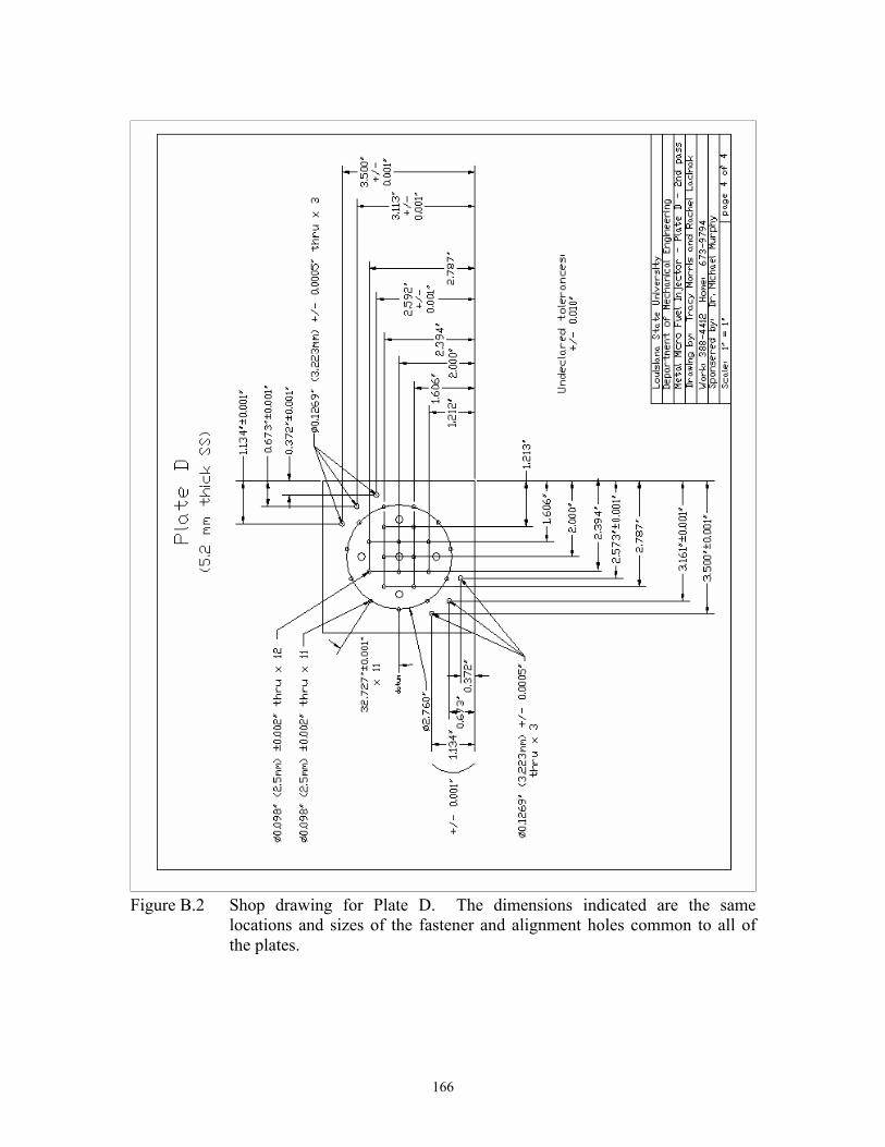
166
Figure B.2 Shop drawing for Plate D. The dimensions indicated are the same locations and sizes of the fastener and alignment holes common to all of the plates.

167
Figure B.3 Specifications for tapping and welding compression fittings into the back
side of Plate D.

168
Figure B.4 Shop drawing for Plate B.

169
Figure B.5 Shop drawing for Plate C.

170
Figure B.6 Shop drawing indicating the differences between Plate A from Plate D.

171
Figure B.7 Shop drawing for the spinning jig used to adapt the spinner holder with the nickel plates.

172
Figure B.8 Proposed drawing for x-ray mask for air-side for compatibility to x-ray
exposure machine. The circular ring indicates the location of a standard NIST stainless steel ring, to which the mask membrane is mounted.

173
Vita
Tracy Morris was born on November 1, 1969 in St. Augustine, Florida to Jane
Swilley Ettel and Ray D. Ettel II. She married Chad Aaron Morris in 1989.
Upon moving to Baton Rouge in May 2001, she began attending Louisiana
State University. She graduated from Louisiana State University with a Bachelor of
Science degree in Mechanical Engineering in 1996. She postponed graduate school to
care for her three children.
In August 1998, she began graduate studies at Louisiana State University. In
September 2001, she began full-time employment with the Center for Advanced
Microfabrication and Devices (CAMD) at Louisiana State University. In December
2001, she successfully defended her thesis. She expected to graduate May 2002 with a
Master of Science in Mechanical Engineering, but was delayed until May 2004.