fabricate parts for sub-assemblies
TRANSCRIPT
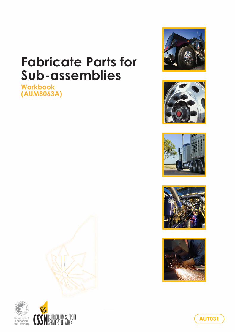
Fabricate Parts for Sub-assemblies Workbook(AUM8063A)
AUT031
AUM8063A
Fabricate Parts for Sub-assemblies
Workbook

Copyright and Terms of Use
© Department of Training and Workforce Development 2016 (unless indicated
otherwise, for example ‘Excluded Material’).
The copyright material published in this product is subject to the Copyright Act 1968
(Cth), and is owned by the Department of Training and Workforce Development or,
where indicated, by a party other than the Department of Training and Workforce
Development. The Department of Training and Workforce Development supports
and encourages use of its material for all legitimate purposes.
Copyright material available on this website is licensed under a Creative Commons
Attribution 4.0 (CC BY 4.0) license unless indicated otherwise (Excluded Material).
Except in relation to Excluded Material this license allows you to:
Share — copy and redistribute the material in any medium or format
Adapt — remix, transform, and build upon the material for any purpose, even commercially
provided you attribute the Department of Training and Workforce Development as
the source of the copyright material. The Department of Training and Workforce
Development requests attribution as: © Department of Training and Workforce
Development (year of publication).
Excluded Material not available under a Creative Commons license:
1. The Department of Training and Workforce Development logo, other logos and trademark protected material; and
2. Material owned by third parties that has been reproduced with permission. Permission will need to be obtained from third parties to re-use their material.
Excluded Material may not be licensed under a CC BY license and can only be used
in accordance with the specific terms of use attached to that material or where
permitted by the Copyright Act 1968 (Cth). If you want to use such material in a
manner that is not covered by those specific terms of use, you must request
permission from the copyright owner of the material.
If you have any questions regarding use of material available in this product, please
contact the Department of Training and Workforce Development.
Training Sector Services
Telephone: 08 6212 9789
Email: [email protected]
Website: www.dtwd.wa.gov.au
First published 2008
Published by and available from
WestOne Services
Prospect Place West Perth WA 6005Tel: (08) 9229 5200 Fax: (08) 9227 8393Email: [email protected]: www.westone.wa.gov.au
Cover images: © 2008 JupiterImages Corporation
© Department of Education and Training 2008
Developed by the Curriculum Support Services Network 2008.
Not for NEALS
Content expertise provided by Colin Russell.
All rights reserved. No part of this publication may be reproduced, stored in a retrieval system or transmitted in any form or by any means, electronic, mechanical, photocopying, recording or otherwise, without the prior written permission of the Western Australian Department of Education and Training.
Whilst every effort has been made to ensure the accuracy of the information contained in this publication, no guarantee can be given that all errors and omissions have been excluded. No responsibility for loss occasioned to any person acting or refraining from action as a result of the material in this publication can be accepted by the Western Australian Department of Education and Training.
ISBN 978-0-7307-9918-4
i
AUM8063A Fabricate Parts for Sub-assemblies
Contents
Introduction............................................................................................................... 1
Sub-assemblies.......................................................................................................... 1
Fabricate parts for sub-assemblies.......................................................................... 3
Order of manufacture and assembly of sub-assemblies....................................... 5
Fixed draw bar trailer cutting list.............................................................................. 6
Standard trailer base frame................................................................................... 7
Fixed draw bar....................................................................................................... 8
Tipping trailer cutting list........................................................................................... 9
Tipping trailer base frame.................................................................................... 10
Tipper draw bar – measurements...................................................................... .11
Tipper draw bar – angles.................................................................................... 12
Draw bar strengthening strap.............................................................................. 13
Tow-hitch plate.................................................................................................... 14
Tipping trailer draw bar pivot............................................................................... 15
Draw bar body guide........................................................................................... 16
Tow-bar hitch....................................................................................................... 17
Axle alignment..................................................................................................... 18
Spring hanger gusset.......................................................................................... 20
Provision for wiring.............................................................................................. 20
Fixed draw bar..................................................................................................... 21
Tipping body........................................................................................................ 22
Sheet management............................................................................................. 23
Body pressing details.......................................................................................... 24
Rear and front side panels.................................................................................. 25
Front and rear gates........................................................................................... 26
Front and rear gates – exercise.......................................................................... 27
Hinges – one pair................................................................................................ 28
Tailgate-locking pin............................................................................................. 29
Holes for rear lights............................................................................................. 30
Rear tailgate – hinge position.............................................................................. 31
Front gate............................................................................................................ 32
ii
AUM8063A Fabricate Parts for Sub-assemblies
Tail-light protector................................................................................................ 33
Mudguards .......................................................................................................... 34
Mudguard positioning.......................................................................................... 35
Rope rails............................................................................................................ 36
Locking bar hinge plate....................................................................................... 37
Locking bar mechanism...................................................................................... 38
Retainer bar.........................................................................................................39
Job completion.................................................................................................... 40
Material costing sheet.............................................................................................. 41
Trailer checklist ........................................................................................................ 43
1
AUM8063A Fabricate Parts for Sub-assemblies
Introduction
Sub-assembliesFabricate Parts for Sub-assemblies is based on a practical project consisting of the manufacture of parts to produce sub-assemblies which, in turn, are brought together to produce a completed vehicle body ready for painting and licensing.
The vehicle chosen for the practical exercise is a box trailer, either a fixed draw bar trailer or a tipping trailer, depending on the cutting list chosen. Students should follow the steps illustrated in the diagrams, noting any instructions or notes given.
From parts to sub-assembliesVehicle bodies are manufactured from a completed series of sub-assemblies. A completed vehicle body appears as a single total unit, but broken down it is actually a series of sub-assemblies which, in turn, are made up of several parts. Together the parts make sub-assemblies and, put together, the sub-assemblies complete the total body.
An example would be a one-tonne tray body consisting of a series of sub-assemblies brought together. The sub-frame is one unit, consisting of several parts such as the main runners, cross bearers and coaming rails. The drop sides are another sub-assembly, made up of the side pressings plus other parts such as end caps, hinges and locks.
The cab rack is also a sub-assembly, made up of parts such as cross rails, uprights and a kick plate.
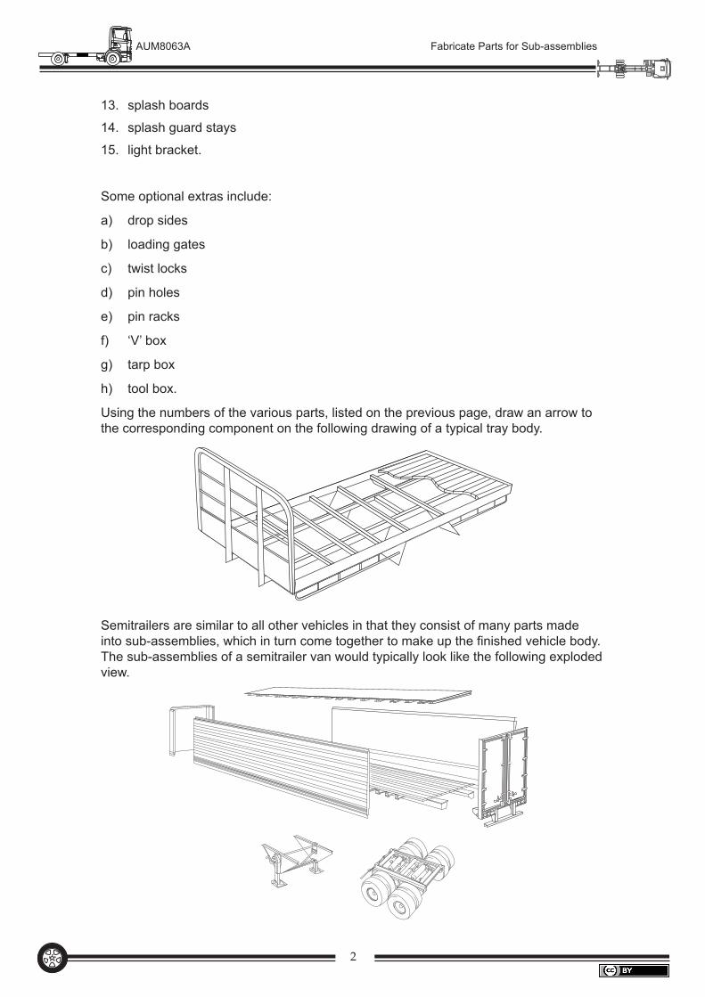
Vehicle body componentsThe following are the parts which would go together to make up sub-assemblies to produce a simple tray body:
1. main runners
2. cross bearers
3. dummy cross bearers
4. coaming rails
5. front and rear coaming
6. cab rack uprights
7. cab rack outer supports
8. cab rack kick rail panel
9. cab rack cross rails
10. rope rails
11. rope rail stays
12. floor
2
AUM8063A Fabricate Parts for Sub-assemblies
13. splash boards
14. splash guard stays
15. light bracket.
Some optional extras include:
a) drop sides
b) loading gates
c) twist locks
d) pin holes
e) pin racks
f) ‘V’ box
g) tarp box
h) tool box.
Using the numbers of the various parts, listed on the previous page, draw an arrow to the corresponding component on the following drawing of a typical tray body.
Semitrailers are similar to all other vehicles in that they consist of many parts made into sub-assemblies, which in turn come together to make up the finished vehicle body. The sub-assemblies of a semitrailer van would typically look like the following exploded view.
3
AUM8063A Fabricate Parts for Sub-assemblies
Fabricate parts for sub-assembliesPractical component
General construction guidelinesAlways wear personal-protective gear.
Cut the longer components first.
Use off-cut material where possible.
Paint between mating parts.
Use anti-spatter on zinc-coated material.
Do not weld across longitudinal beams or members.
Tack weld all components.
Check measurements and squareness before fully welding.
Only fully weld when the sub-assembly is complete and correct.
Use only the minimal amount of weld necessary; do not over weld.
Grind welds as you go.
Avoid sanding away zinc and protective coatings.
Work to a tolerance of ±1 mm.
•
•
•
•
•
•
•
•
•
•
•
•
•
4
AUM8063A Fabricate Parts for Sub-assemblies
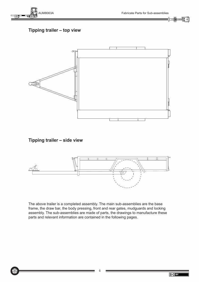
Tipping trailer – top view
The above trailer is a completed assembly. The main sub-assemblies are the base frame, the draw bar, the body pressing, front and rear gates, mudguards and locking assembly. The sub-assemblies are made of parts, the drawings to manufacture these parts and relevant information are contained in the following pages.
Tipping trailer – side view
5
AUM8063A Fabricate Parts for Sub-assemblies
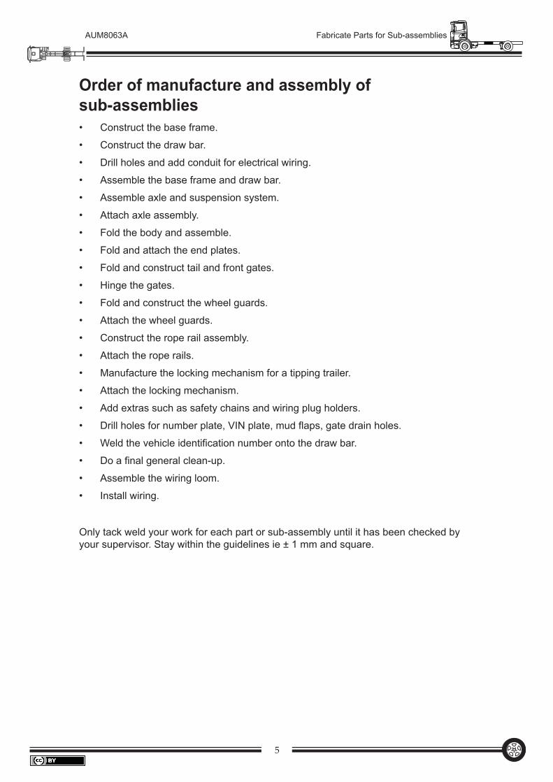
Order of manufacture and assembly of sub-assemblies
Construct the base frame.
Construct the draw bar.
Drill holes and add conduit for electrical wiring.
Assemble the base frame and draw bar.
Assemble axle and suspension system.
Attach axle assembly.
Fold the body and assemble.
Fold and attach the end plates.
Fold and construct tail and front gates.
Hinge the gates.
Fold and construct the wheel guards.
Attach the wheel guards.
Construct the rope rail assembly.
Attach the rope rails.
Manufacture the locking mechanism for a tipping trailer.
Attach the locking mechanism.
Add extras such as safety chains and wiring plug holders.
Drill holes for number plate, VIN plate, mud flaps, gate drain holes.
Weld the vehicle identification number onto the draw bar.
Do a final general clean-up.
Assemble the wiring loom.
Install wiring.
Only tack weld your work for each part or sub-assembly until it has been checked by your supervisor. Stay within the guidelines ie ± 1 mm and square.
•
•
•
•
•
•
•
•
•
•
•
•
•
•
•
•
•
•
•
•
•
•
6
AUM8063A Fabricate Parts for Sub-assemblies
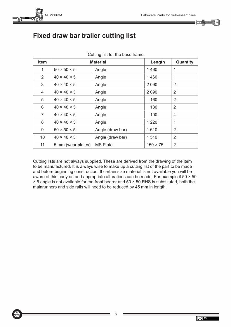
Fixed draw bar trailer cutting list
Cutting list for the base frame
Item Material Length Quantity
1 50 × 50 × 5 Angle 1 460 1
2 40 × 40 × 5 Angle 1 460 1
3 40 × 40 × 5 Angle 2 090 2
4 40 × 40 × 3 Angle 2 090 2
5 40 × 40 × 5 Angle 160 2
6 40 × 40 × 5 Angle 130 2
7 40 × 40 × 5 Angle 100 4
8 40 × 40 × 3 Angle 1 220 1
9 50 × 50 × 5 Angle (draw bar) 1 610 2
10 40 × 40 × 3 Angle (draw bar) 1 510 2
11 5 mm (wear plates) MS Plate 150 × 75 2
Cutting lists are not always supplied. These are derived from the drawing of the item to be manufactured. It is always wise to make up a cutting list of the part to be made and before beginning construction. If certain size material is not available you will be aware of this early on and appropriate alterations can be made. For example if 50 × 50 × 5 angle is not available for the front bearer and 50 × 50 RHS is substituted, both the mainrunners and side rails will need to be reduced by 45 mm in length.
7
AUM8063A Fabricate Parts for Sub-assemblies
2
3
1
8
4
7
8
6
33
6
11 153
5
11
346
55
75
Y Y
2100
745
100
340
1220
100 150 120
130
1395
160
50 x
50
x 5
ang
leex
5m
m M
S p
late
40 x
40
x 3
ang
le
1460
400 400120 120
XX
Pla
n
Fron
t
Det
ail
A
35
Sec
tion
XX
AS
ectio
n Y
YD
etai
l B
12 m
m Ø
hol
efo
r wire
B
1050 11
15
Axl
ec
Sec
tion
on C
Not
e: Che
ck s
prin
g si
zes
befo
refit
ting
parts
No 5
, 4 a
nd 6
.A
ll m
ater
ials
ex
40 x
40
x 5
angl
eun
less
oth
erw
ise
stat
ed.
1. 2.
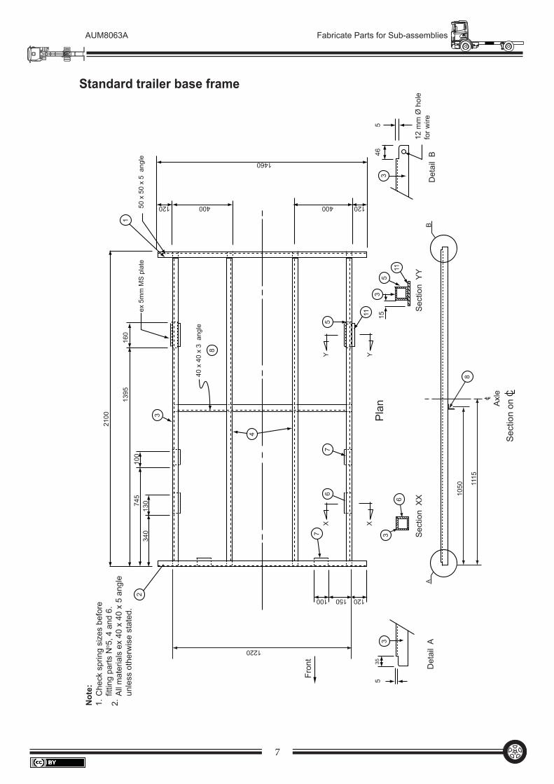
Standard trailer base frame
8
AUM8063A Fabricate Parts for Sub-assemblies
100
80
41
25
1000
450
160
80
910
Tow
-hitc
h pl
ate
Tow
-hitc
h pl
ate
Front of trailer floor
Dra
wba
r det
ail
Det
ail
A(P
late
om
itted
for c
larit
y)
1000
To fr
ont o
f tra
iler
175
910
25 ID
Bla
ck p
ipe
for e
lect
rical
plu
g
Not
e:C
ut o
ne e
nd o
f par
t No
1 as
sho
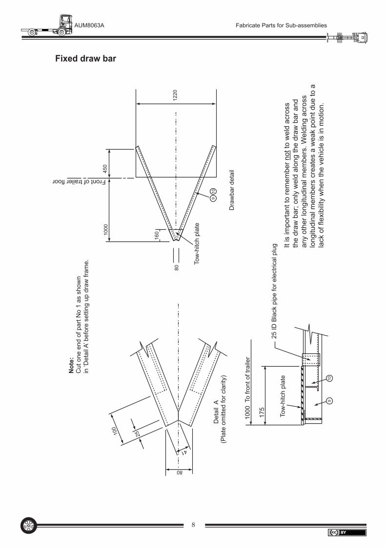
wn
in ‘D
etai
l A’ b
efor
e se
tting
up
draw
fram
e.
1220
Fixed draw bar
It is
impo
rtant
to re
mem
ber n
ot to
wel
d ac
ross
th
e dr
aw b
ar; o
nly
wel
d al
ong
the
draw
bar
and
an
y ot
her l
ongi
tudi
nal m
embe
rs. W
eldi
ng a
cros
s lo
ngitu
dina
l mem
bers
cre
ates
a w
eak
poin
t due
to a
la
ck o
f fle
xibi
lity
whe
n th
e ve
hicl
e is
in m
otio
n.
9
AUM8063A Fabricate Parts for Sub-assemblies
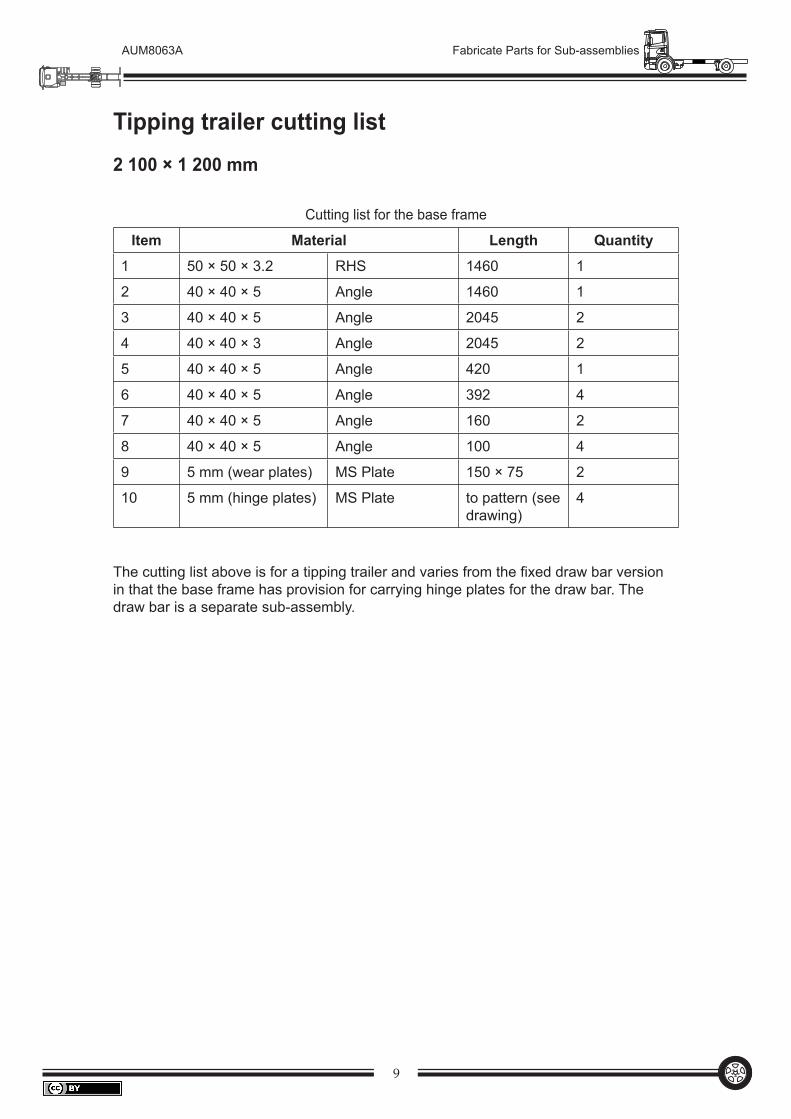
Tipping trailer cutting list2 100 × 1 200 mm
Cutting list for the base frame
Item Material Length Quantity
1 50 × 50 × 3.2 RHS 1460 1
2 40 × 40 × 5 Angle 1460 1
3 40 × 40 × 5 Angle 2045 2
4 40 × 40 × 3 Angle 2045 2
5 40 × 40 × 5 Angle 420 1
6 40 × 40 × 5 Angle 392 4
7 40 × 40 × 5 Angle 160 2
8 40 × 40 × 5 Angle 100 4
9 5 mm (wear plates) MS Plate 150 × 75 2
10 5 mm (hinge plates) MS Plate to pattern (see drawing)
4
The cutting list above is for a tipping trailer and varies from the fixed draw bar version in that the base frame has provision for carrying hinge plates for the draw bar. The draw bar is a separate sub-assembly.
10
AUM8063A Fabricate Parts for Sub-assemblies
2100
AB
1050 11
15
Axl
ec
Sec
tion
on C
Not
e: Che
ck s
prin
g si
zes
befo
refit
ting
parts
No 7
and
8.
All
mat
eria
ls E
X 4
0 x
40 x
5 a
ngle
unle
ss o
ther
wis
e st
ated
.
1. 2.
335
5
3
1
Det
ail
B12
Hol
efo
r wiri
ng
50 x
50
x 3.
2 R
HS
50 x
50
x 3.
2 R
HS
Det
ail
AS
ectio
n X
X
153
7
9
Sec
tion
YY
Ex
5 m
m M
SR
Pla
n
510
63
2
4
8
8
6
97
YX X
Y15
6
Pos
ition
with
dra
wba
r5
mm
MS
R
1220
120 100 150
120
Fron
t
160
1395
745
100
EX
5 m
m M
S P
late
400 120400120
1460
3
8
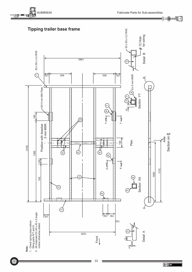
Tipping trailer base frame
11
AUM8063A Fabricate Parts for Sub-assemblies
Rei
nfor
cing
plat
e
65x
35x
3·2
RH
SLo
ckin
gba
rhi
nge
p lat
e
1080
770
100
230
1040
1200
180
100
x55
x5
plat
e12
mm
Øho
lefo
r wire
har
ness
20 m
m Ø
NB
blac
kpi
pe
Not
eN
TS
65x
35x
3·2
RH
S
Sec
tion
onC
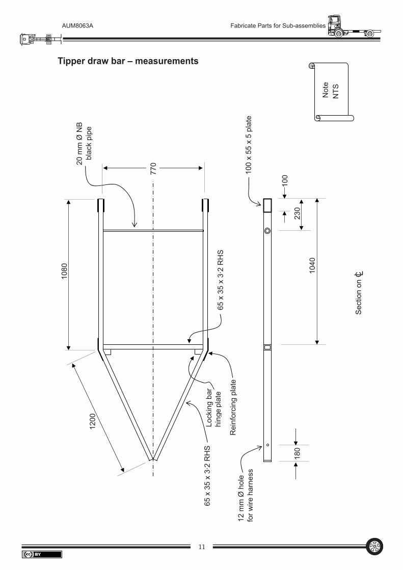
Tipper draw bar – measurements
12
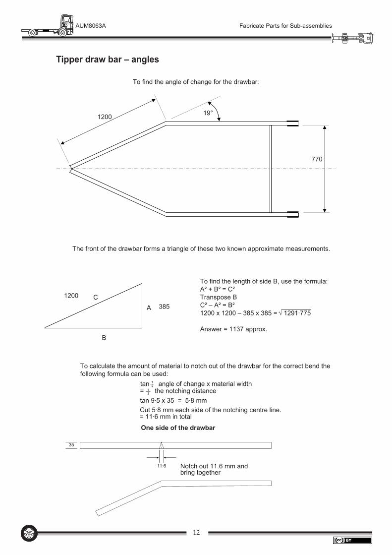
AUM8063A Fabricate Parts for Sub-assemblies
To find the angle of change for the drawbar:
The front of the drawbar forms a triangle of these two known approximate measurements.
770
1200
1200
385A
B
C
To find the length of side B, use the formula:A² + B² = C²Transpose BC² – A² = B²1200 x 1200 – 385 x 385 =
Answer = 1137 approx.
√ 1291·775
19°
To calculate the amount of material to notch out of the drawbar for the correct bend thefollowing formula can be used:
tan angle of change x material width= the notching distancetan 9·5 x 35 = 5·8 mmCut 5·8 mm each side of the notching centre line.= 11·6 mm in total
One side of the drawbar
11·6
35
Notch out 11.6 mm andbring together
12
12
Tipper draw bar – angles
13
AUM8063A Fabricate Parts for Sub-assemblies
55
100100
19°
20
15
20
20
ex 5 mm plate
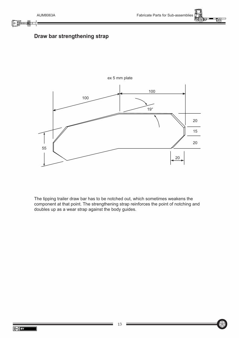
Draw bar strengthening strap
The tipping trailer draw bar has to be notched out, which sometimes weakens the component at that point. The strengthening strap reinforces the point of notching and doubles up as a wear strap against the body guides.
14
AUM8063A Fabricate Parts for Sub-assemblies
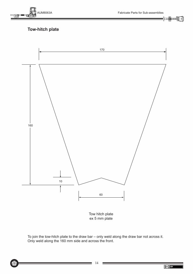
Tow-hitch plate
160
10
60
170
Tow hitch plateex 5 mm plate
To join the tow-hitch plate to the draw bar – only weld along the draw bar not across it. Only weld along the 160 mm side and across the front.
15
AUM8063A Fabricate Parts for Sub-assemblies
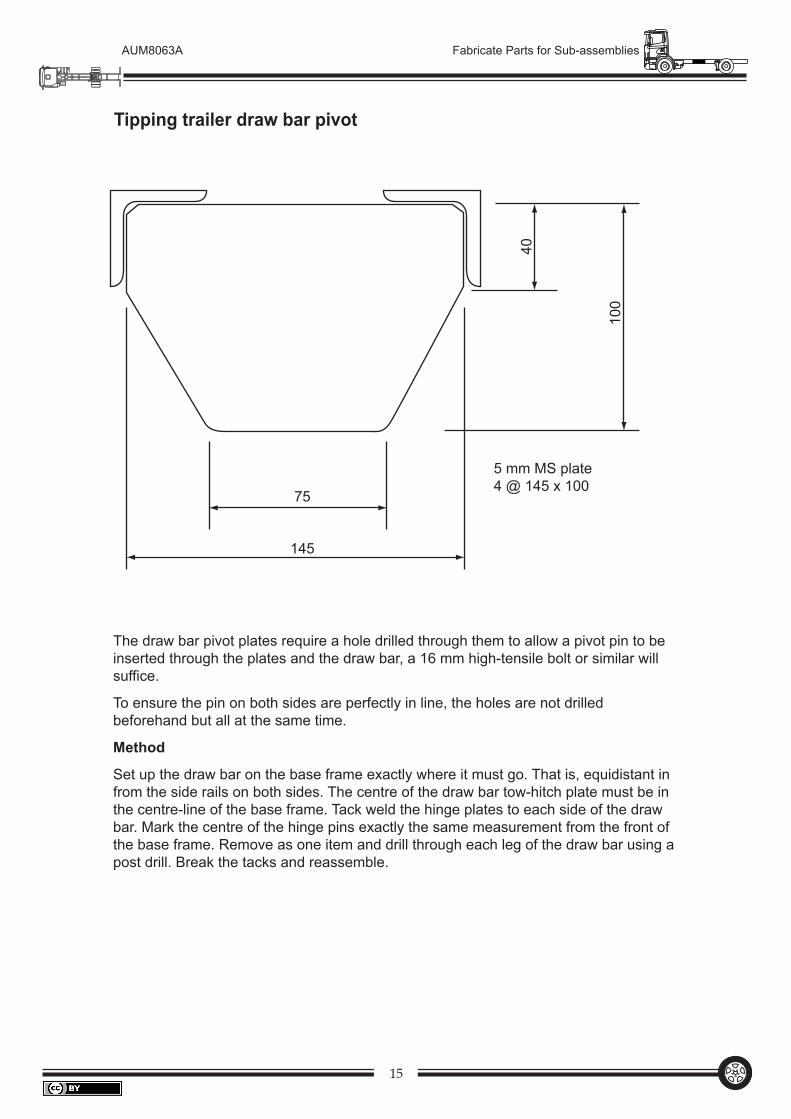
Tipping trailer draw bar pivot
40
75
145
100
5 mm MS plate4 @ 145 x 100
The draw bar pivot plates require a hole drilled through them to allow a pivot pin to be inserted through the plates and the draw bar, a 16 mm high-tensile bolt or similar will suffice.
To ensure the pin on both sides are perfectly in line, the holes are not drilled beforehand but all at the same time.
Method
Set up the draw bar on the base frame exactly where it must go. That is, equidistant in from the side rails on both sides. The centre of the draw bar tow-hitch plate must be in the centre-line of the base frame. Tack weld the hinge plates to each side of the draw bar. Mark the centre of the hinge pins exactly the same measurement from the front of the base frame. Remove as one item and drill through each leg of the draw bar using a post drill. Break the tacks and reassemble.
16
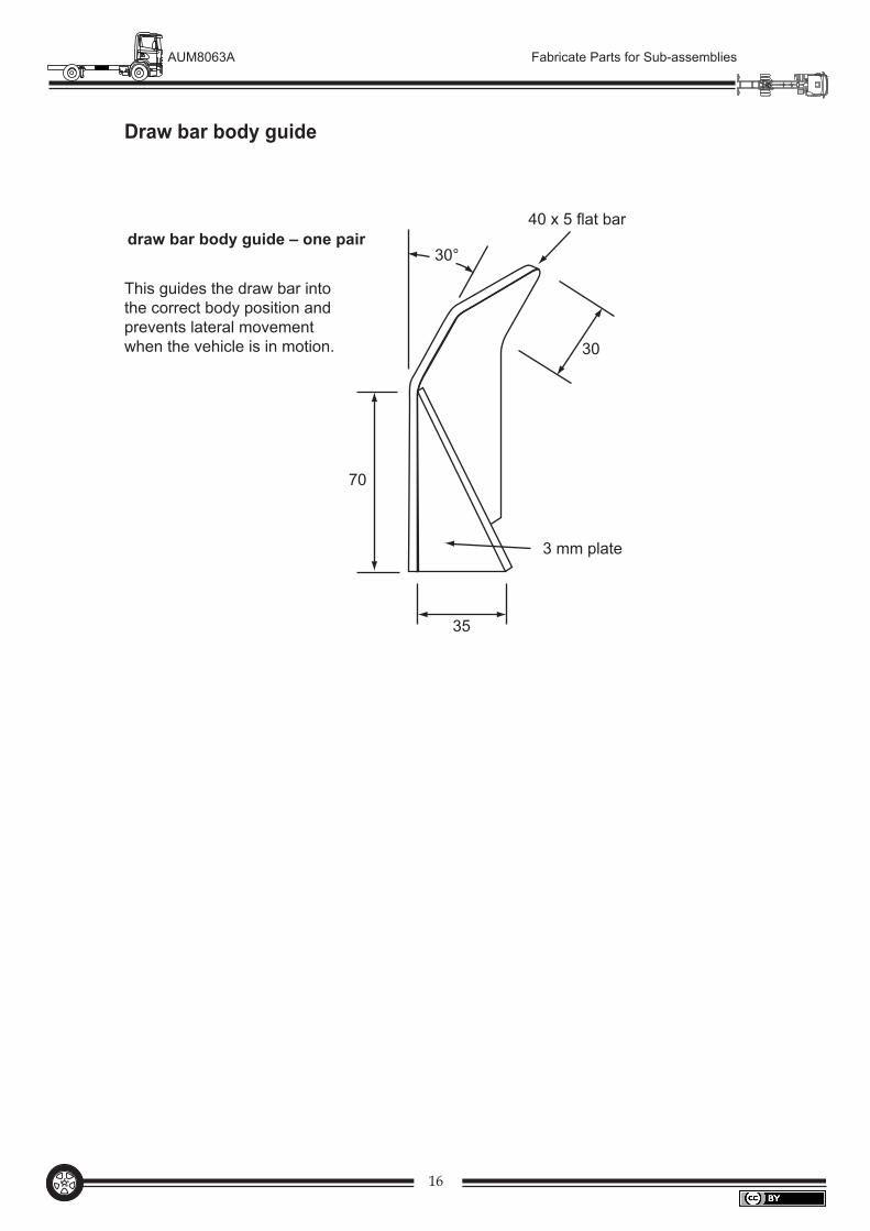
AUM8063A Fabricate Parts for Sub-assemblies
This guides the draw bar into the correct body position and prevents lateral movement when the vehicle is in motion.
Draw bar body guide
35
70
draw bar body guide – one pair30°
40 x 5 flat bar
3 mm plate
30
17
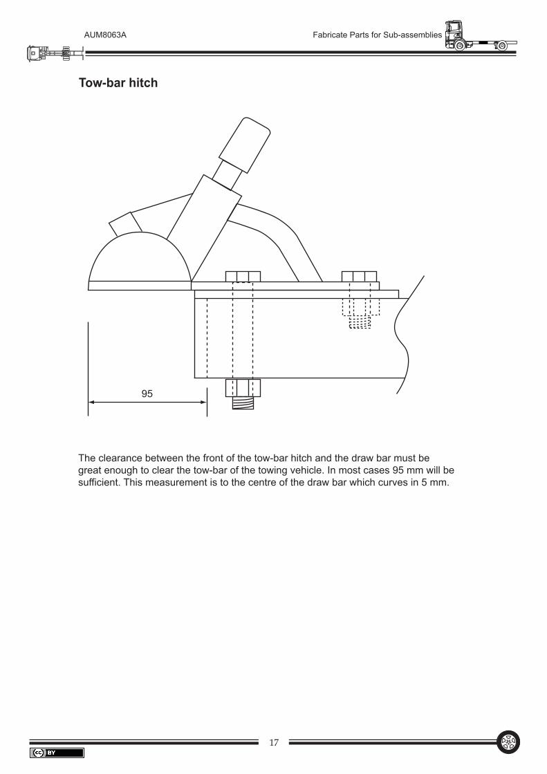
AUM8063A Fabricate Parts for Sub-assemblies
Tow-bar hitch
95
The clearance between the front of the tow-bar hitch and the draw bar must be great enough to clear the tow-bar of the towing vehicle. In most cases 95 mm will be sufficient. This measurement is to the centre of the draw bar which curves in 5 mm.
18
AUM8063A Fabricate Parts for Sub-assemblies
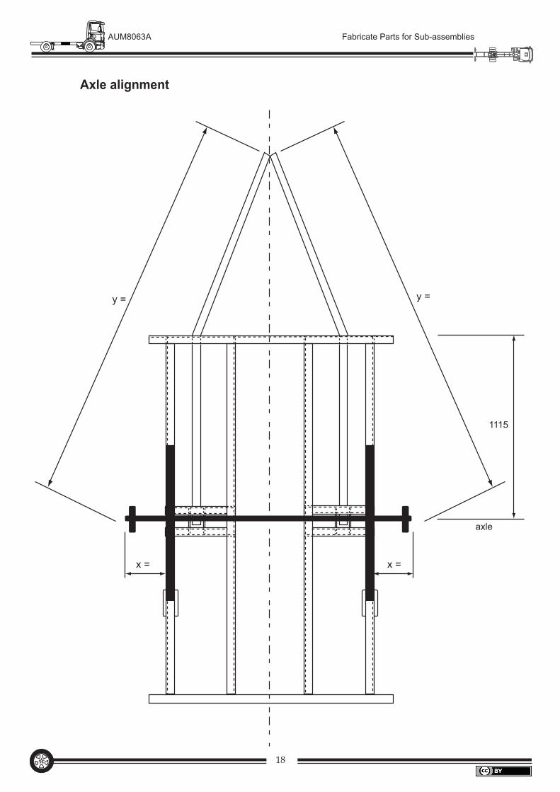
Axle alignment
x = x =
y = y =
1115
axle
19
AUM8063A Fabricate Parts for Sub-assemblies
To line up the axle, it is very important that everything lines up with the centre-line of the vehicle, usually established by using a string line. If the axle is not in line, the trailer will not track correctly, that is, it will want to travel across the road in the direction in which the axle is facing.
Method
Assemble the springs and hubs to the axle.
Measure the distance from the front of the base frame to the centre-line of the axle – in this case 1115 mm. This is back past the centre-line of the trailer to place more mass onto the towing vehicle and ensure better towing.
Measure from the hub to the side rails on both sides – they must be the same. (x)
Measure from the hub to the centre-line at the front of the draw bar, they must be the same. (y)
Once correct, tack weld the front-spring hangers in place and check measurements x and y again.
•
•
•
•
•
20
AUM8063A Fabricate Parts for Sub-assemblies
35
75Spring hanger
Sub-frame main runner
15
3 mm plate
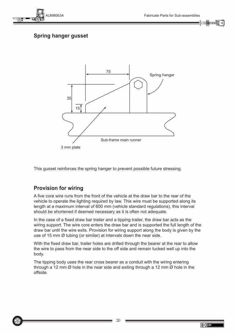
Spring hanger gusset
This gusset reinforces the spring hanger to prevent possible future stressing.
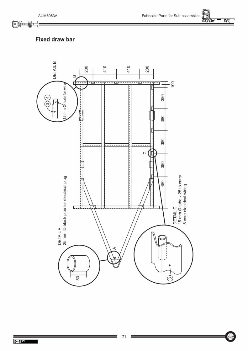
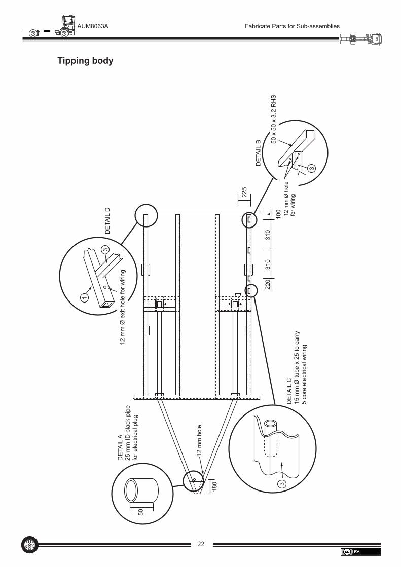
Provision for wiringA five core wire runs from the front of the vehicle at the draw bar to the rear of the vehicle to operate the lighting required by law. This wire must be supported along its length at a maximum interval of 600 mm (vehicle standard regulations), this interval should be shortened if deemed necessary as it is often not adequate.
In the case of a fixed draw bar trailer and a tipping trailer, the draw bar acts as the wiring support. The wire core enters the draw bar and is supported the full length of the draw bar until the wire exits. Provision for wiring support along the body is given by the use of 15 mm Ø tubing (or similar) at intervals down the near side.
With the fixed draw bar, trailer holes are drilled through the bearer at the rear to allow the wire to pass from the near side to the off side and remain tucked well up into the body.
The tipping body uses the rear cross bearer as a conduit with the wiring entering through a 12 mm Ø hole in the near side and exiting through a 12 mm Ø hole in the offside.
21
AUM8063A Fabricate Parts for Sub-assemblies
Fixed draw bar
50
3
3
4
12
mm
Ø h
ole
for w
ire
480
380
380
380
380
100
200
410
410
200
DET
AIL
A25
mm
ID b
lack
pip
e fo
r ele
ctric
al p
lug
DET
AIL
C15
mm
Ø tu
be x
25
to c
arry
5
core
ele
ctric
al w
iring
DET
AIL
B
A
B
C
22
AUM8063A Fabricate Parts for Sub-assemblies
Tipping body
220
310
100
225
310
50
DET
AIL
A25
mm
ID b
lack
pip
efo
r ele
ctric
al p
lug
3D
ETAI
L C
15 m
m Ø
tube
x 2
5 to
car
ry
5 co
re e
lect
rical
wiri
ng
DET
AIL
B
DET
AIL
D
1
3
3
50 x
50
x 3.
2 R
HS
12 m
m Ø
hol
efo
r wiri
ng
12
mm
Ø e
xit h
ole
for w
iring
180
12 m
m h
ole
23
AUM8063A Fabricate Parts for Sub-assemblies
Body
Mud
guar
dM
udgu
ard
Body
Sparematerial
Reargate
Frontgate Gussets
400
2400
2100
1200
400 400
1200
1200
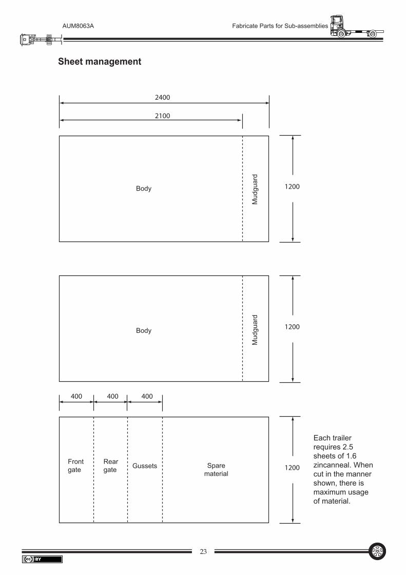
Sheet management
Each trailer requires 2.5 sheets of 1.6 zincanneal. When cut in the manner shown, there is maximum usage of material.
24
AUM8063A Fabricate Parts for Sub-assemblies
190
25
25
35
607
1200
300
18
25
0
0
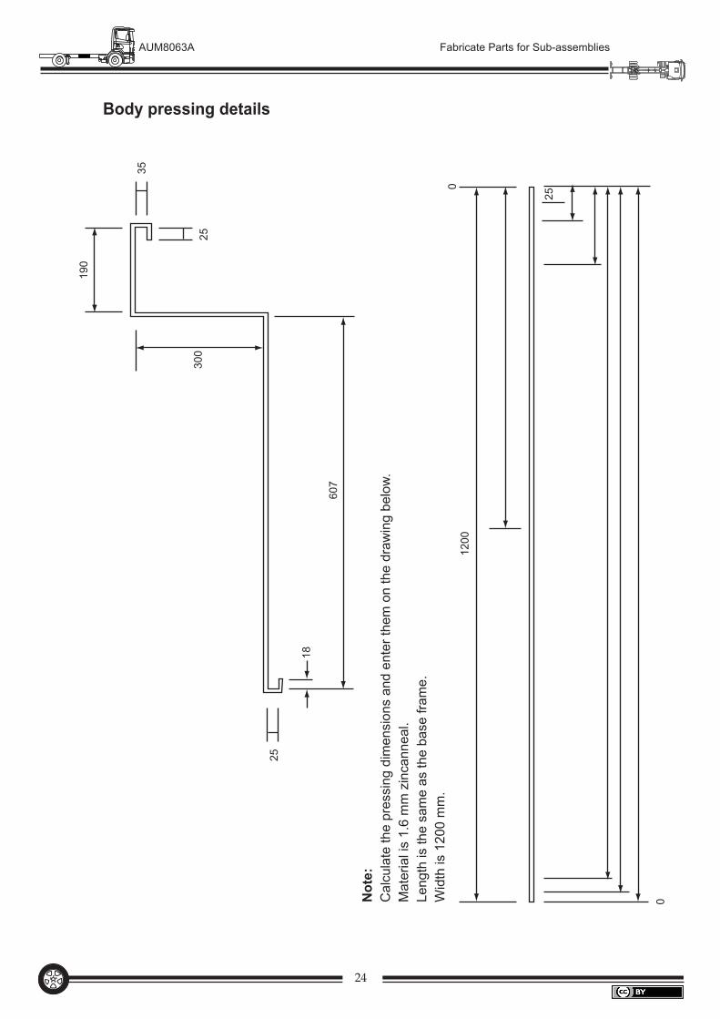
Not
e:C
alcu
late
the
pres
sing
dim
ensi
ons
and
ente
r the
m o
n th
e dr
awin
g be
low
.M
ater
ial i
s 1.
6 m
m z
inca
nnea
l.Le
ngth
is th
e sa
me
as th
e ba
se fr
ame.
Wid
th is
120
0 m
m.
Body pressing details
25
AUM8063A Fabricate Parts for Sub-assemblies
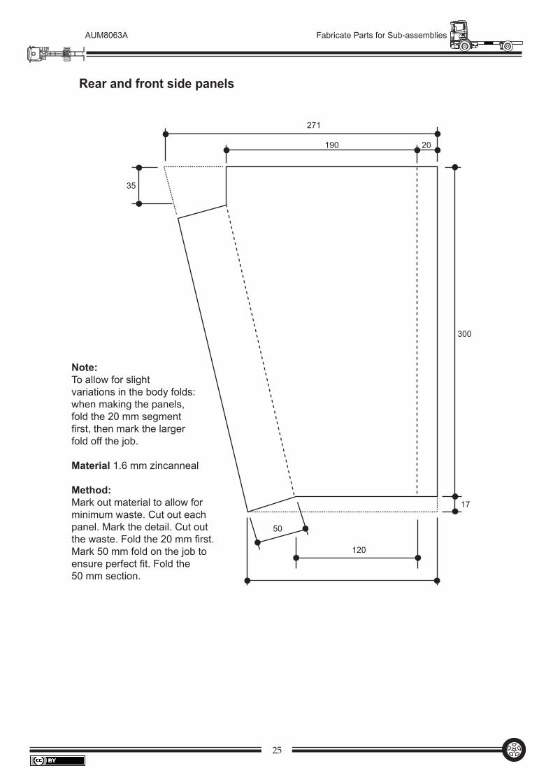
271
35
300
17
50
120
190 20
Note:To allow for slightvariations in the body folds:when making the panels,fold the 20 mm segment first, then mark the largerfold off the job.
Material 1.6 mm zincanneal
Method:Mark out material to allow for minimum waste. Cut out eachpanel. Mark the detail. Cut outthe waste. Fold the 20 mm first.Mark 50 mm fold on the job to ensure perfect fit. Fold the 50 mm section.
Rear and front side panels
26
AUM8063A Fabricate Parts for Sub-assemblies
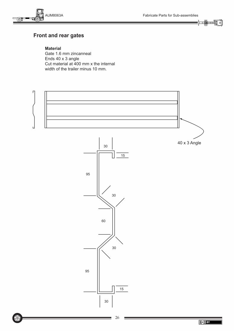
MaterialGate 1.6 mm zincannealEnds 40 x 3 angleCut material at 400 mm x the internalwidth of the trailer minus 10 mm.
40 x 3 Angle30
95
30
60
30
95
30
15
15
Front and rear gates
27
AUM8063A Fabricate Parts for Sub-assemblies
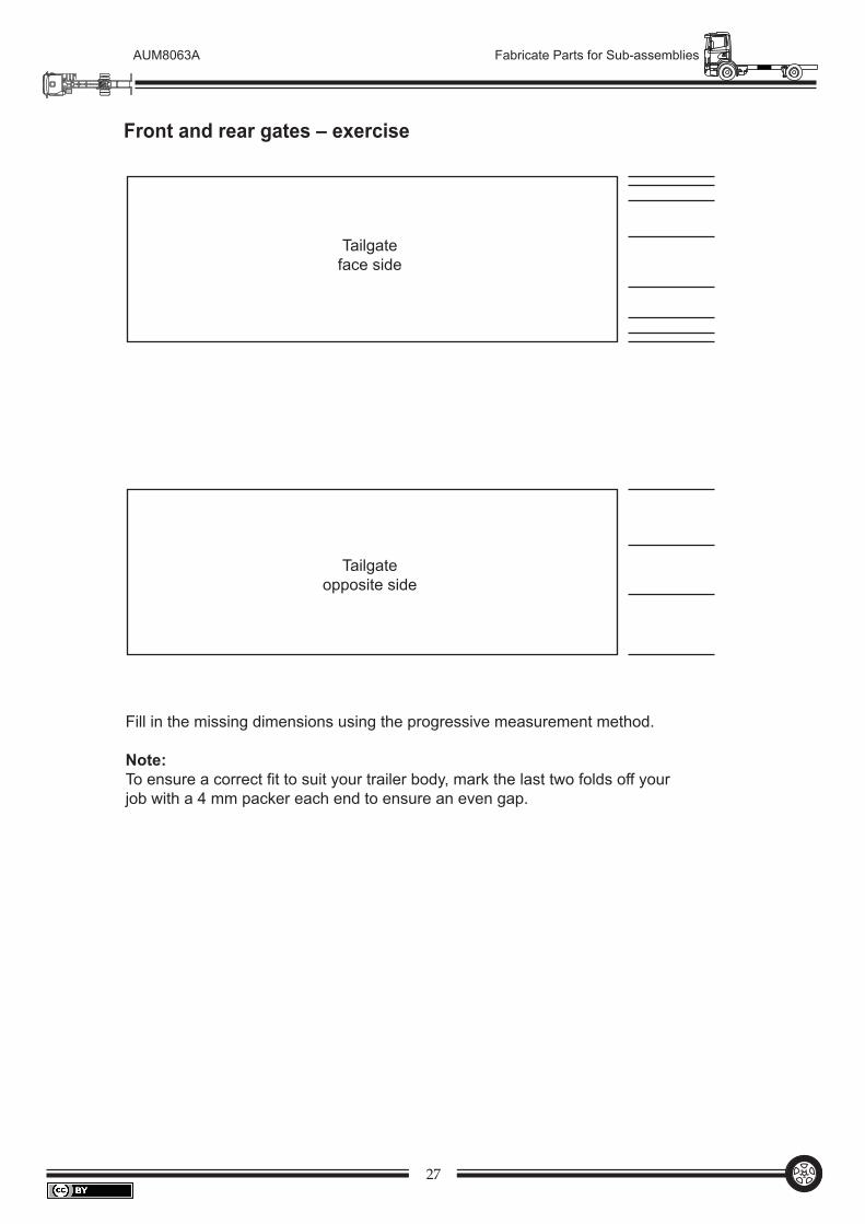
Tailgateface side
Tailgateopposite side
Fill in the missing dimensions using the progressive measurement method.
Note:To ensure a correct fit to suit your trailer body, mark the last two folds off your job with a 4 mm packer each end to ensure an even gap.
Front and rear gates – exercise
28
AUM8063A Fabricate Parts for Sub-assemblies
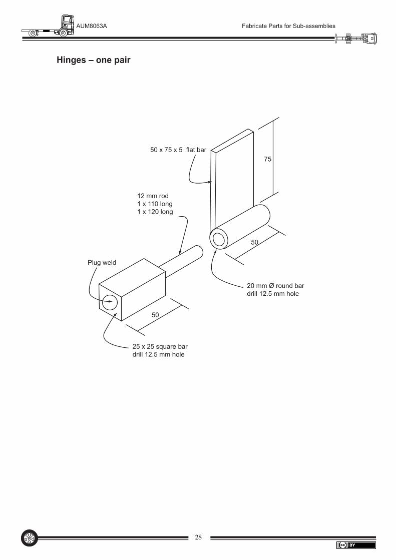
50 x 75 x 5 flat bar
12 mm rod1 x 110 long1 x 120 long
75
50
50
20 mm Ø round bardrill 12.5 mm hole
Plug weld
25 x 25 square bardrill 12.5 mm hole
Hinges – one pair
29
AUM8063A Fabricate Parts for Sub-assemblies
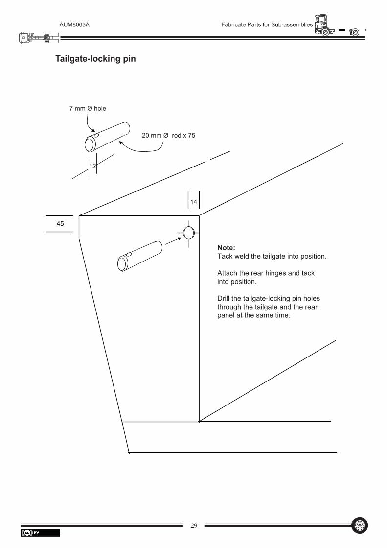
14
7 mm Ø hole
20 mm Ø rod x 75
Note:Tack weld the tailgate into position.
Attach the rear hinges and tack into position.
Drill the tailgate-locking pin holesthrough the tailgate and the rearpanel at the same time.
12
45
Tailgate-locking pin
30
AUM8063A Fabricate Parts for Sub-assemblies
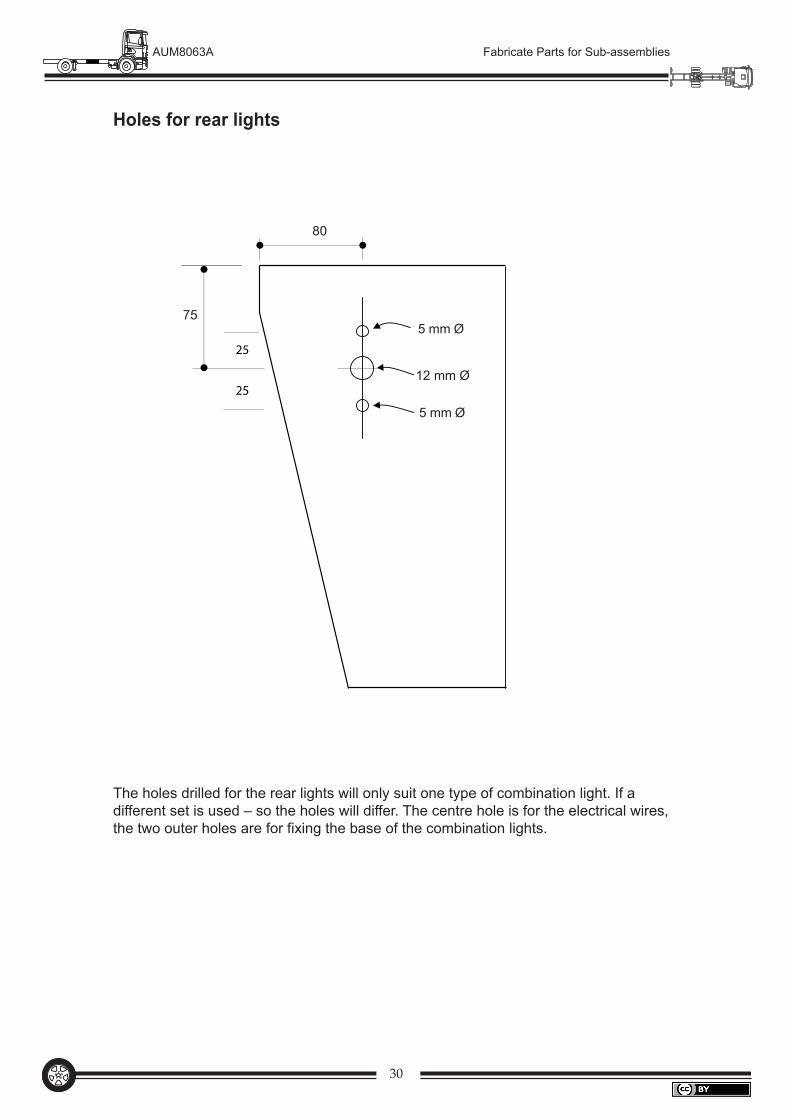
80
755 mm Ø
12 mm Ø
5 mm Ø
25
25
Holes for rear lights
The holes drilled for the rear lights will only suit one type of combination light. If a different set is used – so the holes will differ. The centre hole is for the electrical wires, the two outer holes are for fixing the base of the combination lights.
31
AUM8063A Fabricate Parts for Sub-assemblies
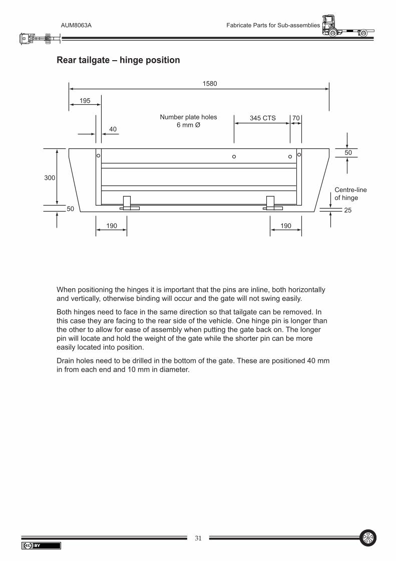
Rear tailgate – hinge position
When positioning the hinges it is important that the pins are inline, both horizontally and vertically, otherwise binding will occur and the gate will not swing easily.
Both hinges need to face in the same direction so that tailgate can be removed. In this case they are facing to the rear side of the vehicle. One hinge pin is longer than the other to allow for ease of assembly when putting the gate back on. The longer pin will locate and hold the weight of the gate while the shorter pin can be more easily located into position.
Drain holes need to be drilled in the bottom of the gate. These are positioned 40 mm in from each end and 10 mm in diameter.
1580
50
190
2550
40
195
345 CTS 70
300
190
Number plate holes6 mm Ø
Centre-lineof hinge
32
AUM8063A Fabricate Parts for Sub-assemblies
Front gate
40
15
40
Centre-line
The front gate is fixed in position with four 6 mm gutter bolts, this provides for removal if required.
Drain holes are drilled in the bottom of the gate. These are positioned 40 mm in from each end and are 10 mm in diameter.
33
AUM8063A Fabricate Parts for Sub-assemblies
45˚
100
30
50
5
ex 50 x 3 flat bar
Tail-light protector
The tail-light protector is to prevent damage to the red lenses of the tail-light in the case of accidental damage – such as reversing into a pole.
They are stitch welded from the underside of the protector so the welds are not visible. Only use the minimal weld such as five stitch welds 10 mm long.
34
AUM8063A Fabricate Parts for Sub-assemblies
15
30
240
20
Cross-section
30º30º
350 400450
Fill in the missing dimensions:
30º
(all insidemeasurements)
Mudguards
Mudguards are a legal requirement on all vehicles. They are designed to prevent water and mud spraying onto following vehicles. They must be as wide as the tyres and low enough at the rear to keep the spray at a low trajectory. To help this, mud flaps are added to the rear of the mudguard.
35
AUM8063A Fabricate Parts for Sub-assemblies
350400
450
120° 120°
(850 approx)
centre-line of the axle
Mudguard positioning
36
AUM8063A Fabricate Parts for Sub-assemblies
210
210
870
655
210
215
215
50
12 m
m ro
dGua
rd
960
20 m
m Ø
tube
sem
i-cru
shed
one
end
50
50
Fron
t rop
e ra
ilR
ear r
ope
rail
210
210
210
215
215
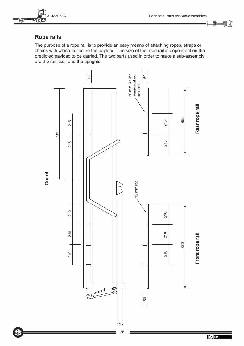
Rope railsThe purpose of a rope rail is to provide an easy means of attaching ropes, straps or chains with which to secure the payload. The size of the rope rail is dependent on the predicted payload to be carried. The two parts used in order to make a sub-assembly are the rail itself and the uprights.
37
AUM8063A Fabricate Parts for Sub-assemblies
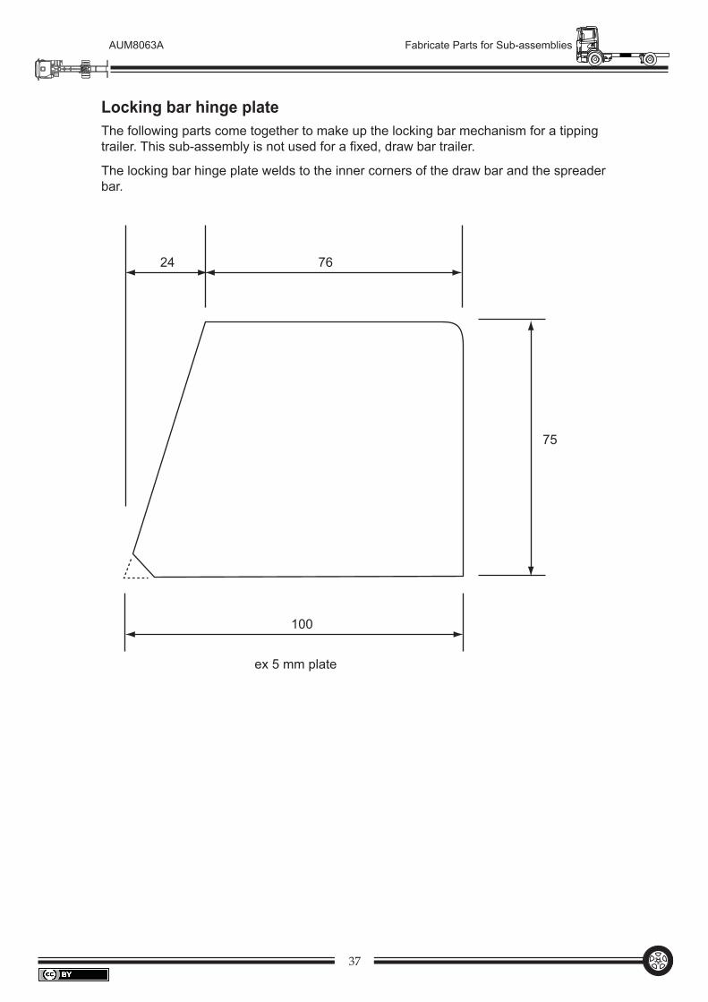
Locking bar hinge plateThe following parts come together to make up the locking bar mechanism for a tipping trailer. This sub-assembly is not used for a fixed, draw bar trailer.
The locking bar hinge plate welds to the inner corners of the draw bar and the spreader bar.
7624
75
100
ex 5 mm plate
38
AUM8063A Fabricate Parts for Sub-assemblies
1
4
5
6
3
2
7
Detail A
Drawbar
1050
320
25º
75 1100
See Detail A
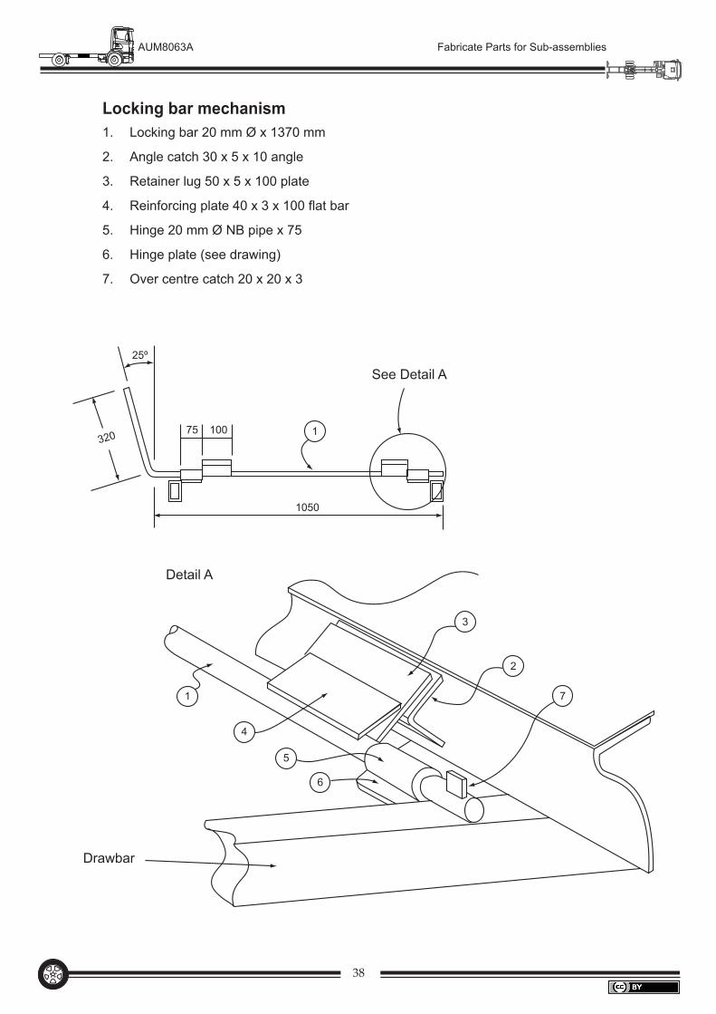
Locking bar mechanism1. Locking bar 20 mm Ø x 1370 mm
2. Angle catch 30 x 5 x 10 angle
3. Retainer lug 50 x 5 x 100 plate
4. Reinforcing plate 40 x 3 x 100 flat bar
5. Hinge 20 mm Ø NB pipe x 75
6. Hinge plate (see drawing)
7. Over centre catch 20 x 20 x 3
39
AUM8063A Fabricate Parts for Sub-assemblies
20
200
75 10
110°
70°
ex 12 mm rod
Retainer bar
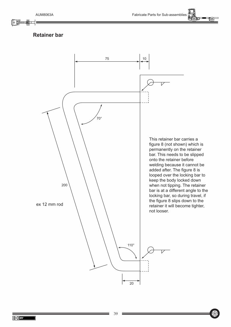
This retainer bar carries a figure 8 (not shown) which is permanently on the retainer bar. This needs to be slipped onto the retainer before welding because it cannot be added after. The figure 8 is looped over the locking bar to keep the body locked down when not tipping. The retainer bar is at a different angle to the locking bar, so during travel, if the figure 8 slips down to the retainer it will become tighter, not looser.
40
AUM8063A Fabricate Parts for Sub-assemblies
Job completionThe following items are the extras which need to be carried out:
all spatter removed
safety chain welded on
nyloc nuts on the spring shackles
nyloc nuts on the ‘U’ bolts
nyloc nuts and washers on the draw bar hinge
holes for the VIN plate
holes for the tail-lights
holes for the tailgate pin chains
drain holes drilled in the bottom of the gates
a safety catch added on from the body to the draw bar for tippers
a VIN number welded onto the draw bar
VIN stamped onto the gates.
At the completion of this project it is obvious that many parts go into making up sub-assemblies and each part is important. For example, a simple tube used to support the wiring, if left out, may cause the vehicle to be rejected at licensing because it would not comply with regulations.
Our project was a simple box trailer, but the same system of fabricating parts for sub-assemblies is applied to larger vehicles, such as semi-tippers and tourist coaches.
As you may have discovered, it is crucial that all parts are made to specifications as they must neatly fit together to produce a sub-assembly and of course the sub-assemblies need to combine accurately to produce a finished vehicle ready to be on the road carrying a payload.
•
•
•
•
•
•
•
•
•
•
•
•

41
AUM8063A Fabricate Parts for Sub-assemblies
Material costing sheetItem Material Length Qty Total
length$ per/m Total cost
$ C

42
AUM8063A Fabricate Parts for Sub-assemblies
Material costing sheet (continued)Item Material Length Qty Total
length$ per/m Total cost
$ C
43
AUM8063A Fabricate Parts for Sub-assemblies
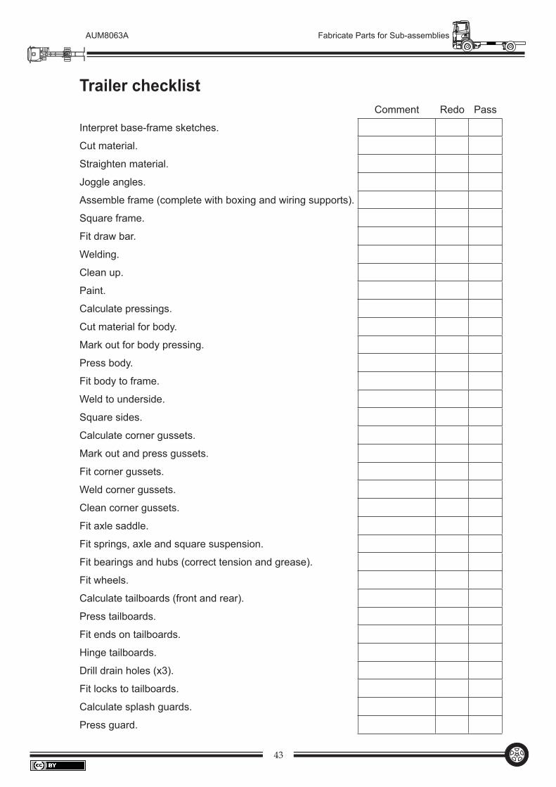
Trailer checklist Comment Redo Pass
Interpret base-frame sketches.
Cut material.
Straighten material.
Joggle angles.
Assemble frame (complete with boxing and wiring supports).
Square frame.
Fit draw bar.
Welding.
Clean up.
Paint.
Calculate pressings.
Cut material for body.
Mark out for body pressing.
Press body.
Fit body to frame.
Weld to underside.
Square sides.
Calculate corner gussets.
Mark out and press gussets.
Fit corner gussets.
Weld corner gussets.
Clean corner gussets.
Fit axle saddle.
Fit springs, axle and square suspension.
Fit bearings and hubs (correct tension and grease).
Fit wheels.
Calculate tailboards (front and rear).
Press tailboards.
Fit ends on tailboards.
Hinge tailboards.
Drill drain holes (x3).
Fit locks to tailboards.
Calculate splash guards.
Press guard.
44
AUM8063A Fabricate Parts for Sub-assemblies
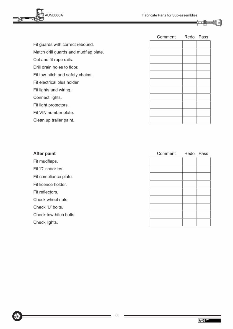
Comment Redo Pass
Fit guards with correct rebound.
Match drill guards and mudflap plate.
Cut and fit rope rails.
Drill drain holes to floor.
Fit tow-hitch and safety chains.
Fit electrical plus holder.
Fit lights and wiring.
Connect lights.
Fit light protectors.
Fit VIN number plate.
Clean up trailer paint.
After paint Comment Redo Pass
Fit mudflaps.
Fit ‘D’ shackles.
Fit compliance plate.
Fit licence holder.
Fit reflectors.
Check wheel nuts.
Check ‘U’ bolts.
Check tow-hitch bolts.
Check lights.

Fabricate Parts for Sub-assembliesWorkbook(AUM8063A)
9 7 8 0 7 3 0 7 9 9 1 8 4
AUT031 FABRICATE PARTS FOR SUB-ASSEMBLIES WORKBOOK
(AUM8063A)ISBN 978-0-7307-9918-4
ORDERING INFORMATION:Contact WestOne Services on Tel: (08) 9229 5200 Fax: (08) 9227 8393 Email: [email protected] can also be placed through the website: www.westone.wa.gov.au
AUT031
DESCRIPTIONThis guide is a practical unit which uses the manufacture and assembly of a simple vehicle body to demonstrate the relationship between fabricated parts, sub-assemblies and the completed article.
The reader is presented with diagrams and drawings of parts to fabricate which in turn make up the sub-assemblies required for a complete body.
EDITIONFirst edition
CATEGORYAutomotive Manufacture
COURSES AND QUALIFICATIONS Certificate III Automotive Manufacture (Bus truck and trailer)
RELATED PRODUCTSAUT032 Perform Gas Metal Arc Welding WorkbookAUT033 Prepare and Operate Equipment, Tools and Machinery - Hand Tools WorkbookAUT034 Prepare and Operate Equipment, Tools and Machinery - Power Tools WorkbookAUT035 Modify or Repair Chassis/Frame and Associated Components Workbook
•
Produced by WestOne Services