faa-ct-8080-4e, computer testing supplement for aviation mechanic general, powerplant ... ·...
TRANSCRIPT

U.S. Department of TransportationFederal Aviation Administration
COMPUTER TESTING SUPPLEMENTFOR
FAA-CT-8080-4E
AVIATION MECHANIC GENERAL,POWERPLANT, AND AIRFRAME;
AND PARACHUTE RIGGER
DO NOT MARK IN THIS BOOK


COMPUTER TESTING SUPPLEMENTFOR
AVIATION MECHANIC GENERAL,POWERPLANT, AND AIRFRAME;
AND PARACHUTE RIGGER
2005
U.S. DEPARTMENT OF TRANSPORTATION
FEDERAL AVIATION ADMINISTRATIONFlight Standards Service


PREFACE
This computer testing supplement is designed by the Flight Standards Service of the Federal Aviation Administration(FAA) for use by computer testing designees (CTDs) in the administration of computer-assisted airman knowledge testsin the following knowledge areas:
Aviation Mechanic General—AMGAviation Mechanic Powerplant—AMPAviation Mechanic Airframe—AMAParachute Rigger—RIG, RMC, RMP
FAA-CT-8080-4E supersedes FAA-CT-8080-4D, Computer Testing Supplement for Aviation Mechanic General,Powerplant, and Airframe; and Parachute Rigger, dated 2001.
Comments regarding this supplement should be sent to:
U.S. Department of TransportationFederal Aviation AdministrationFlight Standards ServiceAirman Testing Standards Branch, AFS-630P.O. Box 25082Oklahoma City, OK 73125
iii


FIGURE 1.—Equation ............................................................................................................................................. 1FIGURE 2.—Equation ............................................................................................................................................. 1FIGURE 3.—Equation ............................................................................................................................................. 1FIGURE 4.—Circuit Diagram .................................................................................................................................. 2FIGURE 5.—Formula .............................................................................................................................................. 2FIGURE 6.—Circuit Diagram .................................................................................................................................. 2FIGURE 7.—Circuit Diagram .................................................................................................................................. 3FIGURE 8.—Circuit Diagram .................................................................................................................................. 3FIGURE 9.—Circuit Diagram .................................................................................................................................. 3FIGURE 10.—Battery Circuit .................................................................................................................................. 4FIGURE 11.—Circuit Diagram ................................................................................................................................ 4FIGURE 12.—Circuit Diagram ................................................................................................................................ 4FIGURE 13.—Circuit Diagram ................................................................................................................................ 5FIGURE 14.—Circuit Diagram ................................................................................................................................ 5FIGURE 15.—Landing Gear Circuit ........................................................................................................................ 6FIGURE 16.—Fuel System Circuit .......................................................................................................................... 7FIGURE 17.—Electrical Symbols ............................................................................................................................ 8FIGURE 18.—Landing Gear Circuit ........................................................................................................................ 9FIGURE 19.—Landing Gear Circuit ........................................................................................................................ 9FIGURE 20.—Circuit Diagram .............................................................................................................................. 10FIGURE 21.—Electrical Symbols .......................................................................................................................... 10FIGURE 22.—Transistors ...................................................................................................................................... 11FIGURE 23.—Transistorized Circuit ..................................................................................................................... 12FIGURE 24.—Logic Gate ...................................................................................................................................... 13FIGURE 25.—Logic Gate ...................................................................................................................................... 13FIGURE 26.—Logic Gates .................................................................................................................................... 14FIGURE 27.—Object Views .................................................................................................................................. 15FIGURE 28.—Object Views .................................................................................................................................. 15FIGURE 29.—Object Views .................................................................................................................................. 16FIGURE 30.—Object Views .................................................................................................................................. 16FIGURE 31.—Sketches ......................................................................................................................................... 17FIGURE 32.—Sketches ......................................................................................................................................... 18FIGURE 33.—Material Symbols ............................................................................................................................ 18FIGURE 34.—Aircraft Drawing ............................................................................................................................. 19FIGURE 35.—Aircraft Drawing ............................................................................................................................. 20FIGURE 36.—Aircraft Drawing ............................................................................................................................. 21FIGURE 37.—Aircraft Drawing ............................................................................................................................. 22FIGURE 38.—Performance Chart ......................................................................................................................... 22FIGURE 39.—Electric Wire Chart ......................................................................................................................... 23FIGURE 40.—Cable Tension Chart ....................................................................................................................... 23FIGURE 41.—Performance Chart ......................................................................................................................... 24FIGURE 42.—Aircraft Hardware .......................................................................................................................... 24FIGURE 43.—Aircraft Hardware .......................................................................................................................... 25
Preface ................................................................................................................................................................ iiiContents ............................................................................................................................................................... v
CONTENTS
APPENDIX 1—AVIATION MECHANIC GENERAL
v
FIGURE 44.—Welds ............................................................................................................................................. 25FIGURE 45.—Welds ............................................................................................................................................. 26FIGURE 46.—Precision Measurement .................................................................................................................. 26FIGURE 47.—Precision Measurement .................................................................................................................. 27FIGURE 48.—Precision Measurement .................................................................................................................. 27FIGURE 49.—Precision Measurement .................................................................................................................. 28FIGURE 50.—Marshalling Signals ......................................................................................................................... 28FIGURE 51.—Marshalling Signals ......................................................................................................................... 29FIGURE 52.—Equation ......................................................................................................................................... 29FIGURE 53.—Equation ......................................................................................................................................... 29FIGURE 54.—Trapezoid Area ............................................................................................................................... 30FIGURE 55.—Triangle Area .................................................................................................................................. 30FIGURE 56.—Trapezoid Area ............................................................................................................................... 30FIGURE 57.—Triangle Area .................................................................................................................................. 31FIGURE 58.—Equation ......................................................................................................................................... 31FIGURE 59.—Equation ......................................................................................................................................... 31FIGURE 60.—Equation ......................................................................................................................................... 32FIGURE 61.—Physics ........................................................................................................................................... 32FIGURE 62.—Part 1 of 3 – Maintenance Data ..................................................................................................... 33FIGURE 62A.—Part 2 of 3 – Maintenance Data ................................................................................................... 34
FIGURE 1.—Rivets ................................................................................................................................................. 1FIGURE 2.—Countersinking ................................................................................................................................... 1FIGURE 3.—Grip Length ........................................................................................................................................ 1FIGURE 4.—Bending Sheet Metal .......................................................................................................................... 2
CONTENTS—Continued
FIGURE 62B.—Part 3 of 3 – Maintenance Data ................................................................................................... 35FIGURE 63.—Airworthiness Directive Excerpt ..................................................................................................... 36FIGURE 64.—Resistance Total ............................................................................................................................. 37FIGURE 65.—Scientific Notation .......................................................................................................................... 37FIGURE 66.—Equation ......................................................................................................................................... 37FIGURE 67.—Equation ......................................................................................................................................... 37FIGURE 68.—Alternative Answer ......................................................................................................................... 38FIGURE 69.—Equation ......................................................................................................................................... 38FIGURE 70.—Alternative Answer ......................................................................................................................... 38FIGURE 71.—Volume of a Sphere ........................................................................................................................ 38
APPENDIX 3—AVIATION MECHANIC AIRFRAME
vi
FIGURE 1.—Airworthiness Directive Excerpt ......................................................................................................... 1FIGURE 2.—Fire Extinguisher Pressure Chart ........................................................................................................ 2FIGURE 3.—Fire Extinguisher Pressure Chart ........................................................................................................ 2FIGURE 4.—Electric Wire Chart ............................................................................................................................. 3FIGURE 5.—Starter-Generator Circuit .................................................................................................................... 4FIGURE 6.—Fuel/Air Ratio Graphs ......................................................................................................................... 5FIGURE 7.—Fuel System........................................................................................................................................ 6
APPENDIX 2—AVIATION MECHANIC POWERPLANT
FIGURE 1.—Tacking Knot ..................................................................................................................................... 1FIGURE 2.—Parachute Material ............................................................................................................................ 1FIGURE 3.—Seam Stitching .................................................................................................................................. 2FIGURE 4.—Suspension Line Attachment ............................................................................................................. 2FIGURE 5.—Suspension Lines ............................................................................................................................... 3FIGURE 6.—Fittings .............................................................................................................................................. 3FIGURE 7.—Radial Seam Stitching ....................................................................................................................... 4FIGURE 8.—Lift Web Stitching ............................................................................................................................. 4FIGURE 9.—Knots ................................................................................................................................................. 5FIGURE 10.—Machine Stitching ........................................................................................................................... 5FIGURE 11.—French Fell Seam............................................................................................................................. 6FIGURE 12.—English Fell Seam ........................................................................................................................... 6FIGURE 13.—Machine Stitching ........................................................................................................................... 7FIGURE 14.—Machine Stitching ........................................................................................................................... 7FIGURE 15.—Machine Stitching ........................................................................................................................... 7FIGURE 16.—Hardware Threading ....................................................................................................................... 8
FIGURE 13.—Cooling System ............................................................................................................................... 6FIGURE 14.—Pressure Temperature Correction Chart .......................................................................................... 6FIGURE 15.—Formula ........................................................................................................................................... 7FIGURE 16.—Antennas ......................................................................................................................................... 7FIGURE 17.—Fuel System ..................................................................................................................................... 7FIGURE 18.—Battery Connections ........................................................................................................................ 8FIGURE 19.—Landing Gear Circuit ...................................................................................................................... 9FIGURE 20.—Landing Gear Circuit .................................................................................................................... 10FIGURE 21.—Fire Extinguisher Chart ................................................................................................................. 10
APPENDIX 4—PARACHUTE RIGGER
CONTENTS—Continued
vii
FIGURE 5.—Sheet Metal Layout ............................................................................................................................ 2FIGURE 6.—Sheet Metal Layout ............................................................................................................................ 3FIGURE 7.—Sheet Metal Layout ............................................................................................................................ 3FIGURE 8.—Control Cable ..................................................................................................................................... 4FIGURE 9.—Cable Tension Chart ........................................................................................................................... 4FIGURE 10.—Torque Value .................................................................................................................................... 5FIGURE 11.—Fittings .............................................................................................................................................. 5FIGURE 12.—Backup Rings ................................................................................................................................... 5

Aviation Mechanic General

Appendix 1
1
Aviation Mechanic General
CT 1/C + 1/C + 1/C . . .1 2 3
1=
FIGURE 1.—Equation.
FIGURE 2.—Equation.
FIGURE 3.—Equation.
CT1 2 3
1= 1/C + 1/C + 1/C
LT 1/L + 1/L + 1/L . . .1 2 3
1=

Appendix 1
2
Aviation Mechanic General
Z = R2 + (XL – X
C)2
Z =ImpedanceR =ResistanceX
L=Inductive Reactance
XC
=Capacitive Reactance
FIGURE 4.—Circuit Diagram.
FIGURE 5.—Formula.
FIGURE 6.—Circuit Diagram.

Appendix 1
3
Aviation Mechanic General
FIGURE 7.—Circuit Diagram.
FIGURE 8.—Circuit Diagram.
FIGURE 9.—Circuit Diagram.

Appendix 1
4
Aviation Mechanic General
FIGURE 10.—Battery Circuit.
FIGURE 12.—Circuit Diagram.
FIGURE 11.—Circuit Diagram.

Appendix 1
5
Aviation Mechanic General
FIGURE 14.—Circuit Diagram.
FIGURE 13.—Circuit Diagram.

Appendix 1
6
Aviation Mechanic General
FIGURE 15.—Landing Gear Circuit.

Appendix 1
7
Aviation Mechanic General
FIGURE 16.—Fuel System Circuit.

Appendix 1
8
Aviation Mechanic General
FIGURE 17.—Electrical Symbols.

Appendix 1
9
Aviation Mechanic General
FIGURE 19.—Landing Gear Circuit.
FIGURE 18.—Landing Gear Circuit.

Appendix 1
10
Aviation Mechanic General
FIGURE 20.—Circuit Diagram.
FIGURE 21.—Electrical Symbols.
1
2
3

Appendix 1
11
Aviation Mechanic General
FIGURE 22.—Transistors.
1 2
3

Appendix 1
12
Aviation Mechanic General
FIGURE 23.—Transistorized Circuit.

Appendix 1
13
Aviation Mechanic General
FIGURE 24.—Logic Gate.
FIGURE 25.—Logic Gate.

Appendix 1
14
Aviation Mechanic General
FIGURE 26.—Logic Gates.
2
3
Appendix 1
15
Aviation Mechanic General
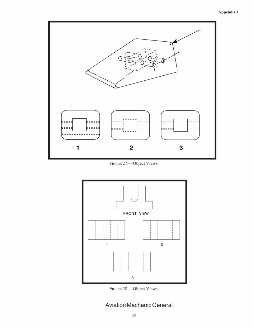
FIGURE 28.—Object Views.
FIGURE 27.—Object Views.
1 2 3

Appendix 1
16
Aviation Mechanic General
FIGURE 29.—Object Views.
FIGURE 30.—Object Views.
1 2 3
1 2 3

Appendix 1
17
Aviation Mechanic General
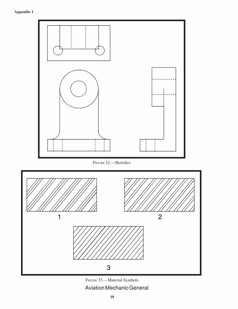
FIGURE 31.—Sketches.
Appendix 1
18
Aviation Mechanic General
FIGURE 33.—Material Symbols.
FIGURE 32.—Sketches.

Appendix 1
19
Aviation Mechanic General
FIGURE 34.—Aircraft Drawing.
Appendix 1
20
Aviation Mechanic General
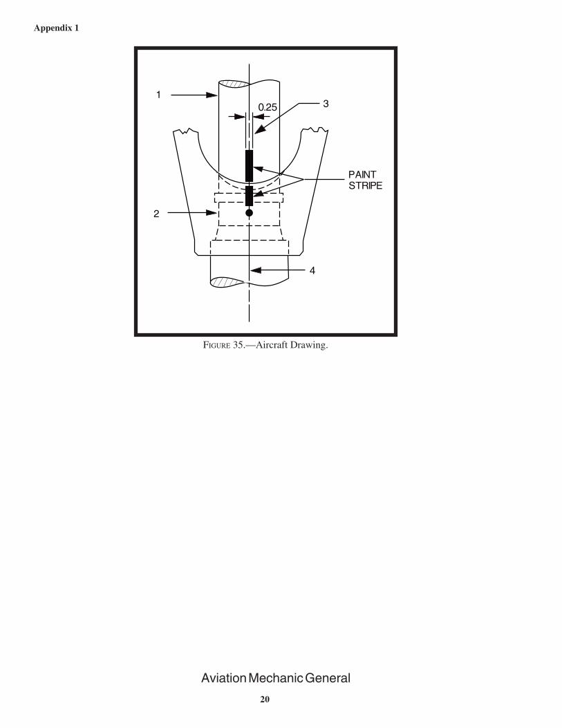
FIGURE 35.—Aircraft Drawing.

Appendix 1
21
Aviation Mechanic General
FIGURE 36.—Aircraft Drawing.

Appendix 1
22
Aviation Mechanic General
FIGURE 37.—Aircraft Drawing.
FIGURE 38.—Performance Chart.
Appendix 1
23
Aviation Mechanic General
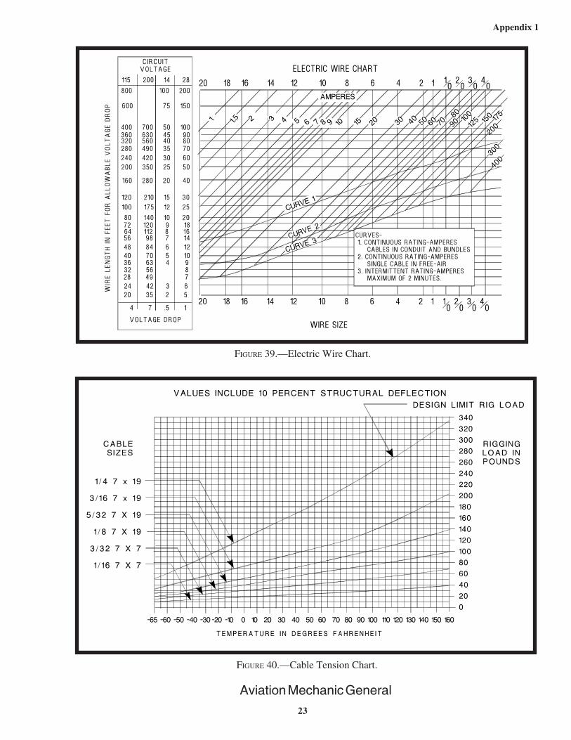
FIGURE 39.—Electric Wire Chart.
FIGURE 40.—Cable Tension Chart.

Appendix 1
24
Aviation Mechanic General
FIGURE 41.—Performance Chart.
FIGURE 42.—Aircraft Hardware.

Appendix 1
25
Aviation Mechanic General
FIGURE 43.—Aircraft Hardware.
FIGURE 44.—Welds.
1 2 3
11111
33333
22222
44444

Appendix 1
26
Aviation Mechanic General
FIGURE 45.—Welds.
FIGURE 46.—Precision Measurement.

Appendix 1
27
Aviation Mechanic General
FIGURE 47.—Precision Measurement.
FIGURE 48.—Precision Measurement.

Appendix 1
28
Aviation Mechanic General
FIGURE 49.—Precision Measurement.
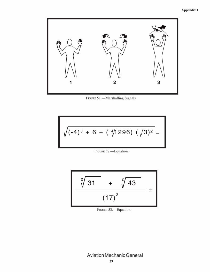
FIGURE 50.—Marshalling Signals.
1 2 3
Appendix 1
29
Aviation Mechanic General
4(-4) + 6 + ( 1296) ( 3)² =0
FIGURE 51.—Marshalling Signals.
FIGURE 52.—Equation.
31 + 4322
(17)2
=
FIGURE 53.—Equation.
1 2 3

Appendix 1
30
Aviation Mechanic General
FIGURE 54.—Trapezoid Area.
FIGURE 55.—Triangle Area.
FIGURE 56.—Trapezoid Area.
7.5"
3"
4"

Appendix 1
31
Aviation Mechanic General
FIGURE 57.—Triangle Area.
FIGURE 58.—Equation.
FIGURE 59.—Equation.
π

Appendix 1
32
Aviation Mechanic General
FIGURE 61.—Physics.
FIGURE 60.—Equation.
( -5 + 23) (-2 ) + (3 ) ( )-3
64
-27 ÷ 9=

Appendix 1
33
Aviation Mechanic General
FIG
UR
E 6
2.—
Part
1 o
f 3
– M
aint
enan
ce D
ata.

Appendix 1
34
Aviation Mechanic General
FIGURE 62A.—Part 2 of 3 – Maintenance Data.
GENERAL NOTES -200 Note: P. S. = Process SpecificationIAW = in accordance with
All bends IAW P. S. 1000.All holes IAW P. S. 1015.Heat treat -102 to -T6 IAW P. S. 5602.Alodine IAW P. S. 10000.Prime IAW P. S. 10125.Trim S-1 C just aft of the clip at STA. 355.750 and forward of the front face of theSTA. 370.25 frame and remove from airplane.Position the -102 doubler as shown. Install wet with NAS1097AD-4-4 and -4-5 rivets, anda faying surface seal IAW P. S. 41255. Pick up the rivet row that was in S-1 Cand the aft rivets in STA. 370.25. Add two edge rows as shown. Tie doubler into frontframe with clips as shown using MS20470AD-4-4 rivets through the clips and the frame.Install 4 NAS1473-3A nutplates with NAS1097-3-4 rivets through the skin and doubler toretain the antenna.Strip paint and primer from under the antenna footprint.Treat skin IAW P.S. 10000.Install antenna and apply weather seal fillet around antenna base.
GENERAL NOTES -100
ALL BENDS +/- .5 deg.All holes +/- .003.Apply Alodine 1000.Prime with MIL-P-23377 or equivalent.Trim S-1 C just aft of the clip at STA. 355.750 and forward of the front face of theSTA. 370.25 frame and remove from the airplane.Position the -101 doubler as shown. Install wet with NAS1097AD-4-4 and -4-5 rivetsand a faying surface seal of PR 1422. Pick up the rivet row that was in S-1 C and theaft rivets in sta. 370.25. Tie doubler into front frame with clips as shown usingMS20470AD-4-4 rivets through the clips and the frame.Install 4 NAS1473-3A nutplates with NAS1097-3-4 rivets through the skin and doubler toretain the antenna.Strip paint and primer from under the antenna footprint.Treat skin with Alodine 1000.Install antenna and apply weather seal fillet around antenna base.
1.2.3.4.5.6.
7.
8.
9.10.11.
1.2.3.4.5.
6.
7.
8.9.10.

Appendix 1
35
Aviation Mechanic General
FIG
UR
E 6
2B.—
Part
3 o
f 3
– M
aint
enan
ce D
ata.

Appendix 1
36
Aviation Mechanic General
The following is the compliance portion of an Airworthiness Directive. "Compliance required asindicated, unless already accomplished:
I. Aircraft with less than 500-hours' total time in service: Inspect in accordance withinstructions below at 500-hours' total time, or within the next 50-hours' time in service after theeffective date of this AD, and repeat after each subsequent 200 hours in service.
II. Aircraft with 500-hours' through 1,000-hours' total time in service: Inspect in accordancewith instructions below within the next 50-hours' time in service after the effective date of thisAD, and repeat after each subsequent 200 hours in service.
III. Aircraft with more than 1,000-hours' time in service: Inspect in accordance withinstructions below within the next 25-hours' time in service after the effective date of this AD,and repeat after each subsequent 200 hours in service."
FIGURE 63.—Airworthiness Directive Excerpt.

Appendix 1
37
FIGURE 64.— Resistance Total.
FIGURE 65.—Scientific Notation.
FIGURE 66.— Equation.
FIGURE 67.—Equation.

Appendix 1
38
FIGURE 68.—Alternative Answer.
FIGURE 69.—Equation.
FIGURE 70.—Alternative Answer.
FIGURE 71.—Volume of a Sphere.

Aviation Mechanic Powerplant

1
Appendix 2
Aviation Mechanic Powerplant
This is the compliance portion of an FAA Airworthiness Directive.
Compliance required as indicated:
(A) For model O-690 series engines, serial Nos. 101-40 through 5264-40 and IO-690 seriesengines, serial Nos. 101-48 through 423-48, compliance with (C) required within 25 hours' time inservice after the effective date of this AD and every 100 hours' time in service thereafter.
(B) For Model O-690 series engines, serial Nos. 5265-40 through 6129-40 and IO-690 seriesengines, serial Nos. 424-48 through 551-48, compliances with (C) required as follows:
(1) Within 25 hours' time in service after the effective date of this AD and every 100hours' time in service thereafter for engines with more than 275 hours' time in service on theeffective date of this AD.
(2) Prior to the accumulation of 300 hours total time in service and every 100 hours'time in service thereafter for engines with 275 hours or less time in service on the effectivedate of this AD.
(C) Inspect the oil pump drive shaft (P/N 67512) on applicable engines in accordance withinstructions contained in Connin Service Bulletin No. 295. Any shafts which are found to bedamaged shall be replaced before further flight. These inspections shall be continued until ConninP/N 67512 (redesigned) or P/N 74641 oil pump drive shaft is installed at which time the inspectionsmay be discontinued.
FIGURE 1.—Airworthiness Directive Excerpt.

2
Appendix 2
Aviation Mechanic Powerplant
FIGURE 2.—Fire Extinguisher Pressure Chart.
FIGURE 3.—Fire Extinguisher Pressure Chart.

3
Appendix 2
Aviation Mechanic Powerplant
FIGURE 4.—Electric Wire Chart.

4
Appendix 2
Aviation Mechanic Powerplant
FIGURE 5.—Starter-Generator Circuit.

5
Appendix 2
Aviation Mechanic Powerplant
FIGURE 6.—Fuel/Air Ratio Graphs.

6
Appendix 2
Aviation Mechanic Powerplant
FIGURE 7.—Fuel System.

Aviation Mechanic Airframe

1
Appendix 3
Aviation Mechanic Airframe
FIGURE 2.—Countersinking.
FIGURE 3.—Grip Length.
FIGURE 1.—Rivets.

2
Appendix 3
Aviation Mechanic Airframe
FIGURE 5.—Sheet Metal Layout.
FIGURE 4.—Bending Sheet Metal.

3
Appendix 3
Aviation Mechanic Airframe
FIGURE 6.—Sheet Metal Layout.
FIGURE 7.—Sheet Metal Layout.

4
Appendix 3
Aviation Mechanic Airframe
FIGURE 9.—Cable Tension Chart.
FIGURE 8.—Control Cable.
5
Appendix 3
Aviation Mechanic Airframe
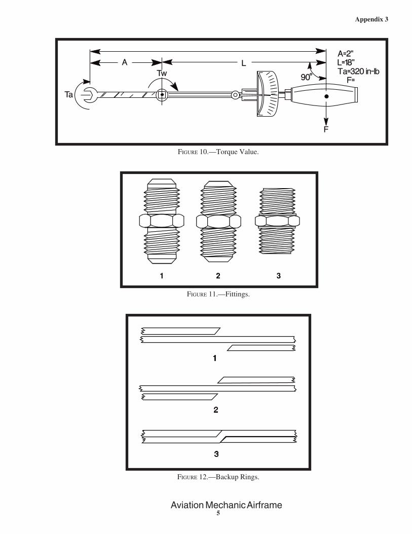
FIGURE 12.—Backup Rings.
FIGURE 11.—Fittings.
FIGURE 10.—Torque Value.

6
Appendix 3
Aviation Mechanic Airframe
FIGURE 13.—Cooling System.
FIGURE 14.—Pressure Temperature Correction Chart.

7
Appendix 3
Aviation Mechanic Airframe
D=.000327AV2
FIGURE 15.—Formula.
FIGURE 16.—Antennas.
FIGURE 17.—Fuel System.

8
Appendix 3
Aviation Mechanic Airframe
FIGURE 18.—Battery Connections.

9
Appendix 3
Aviation Mechanic Airframe
FIGURE 19.—Landing Gear Circuit.

10
Appendix 3
Aviation Mechanic Airframe
FIGURE 20.—Landing Gear Circuit.
FIGURE 21.—Fire Extinguisher Chart.