faa-ads- 28 metallurgical evaluation failed · pdf fileanalysis amples ... metallurgical...
TRANSCRIPT
FAA-ADS- 28
METALLURGICAL EVALUATION OF FAILEDSAIRCRAFT STAINLESS STEEL EXHAUST SYSTEM
COMPONENTS
TECHNICAL REPORT
(4 -. ,,_-•.._-,-- * iIAT Af
'RD COPY $ . ..- , o, ,.'. t'•lIUI H -•
JANUARY 1965 UZ•.••,•L•.~U "I'-TJSfA L
bvT. H. McCunn
Allegheny Ludlum Steel CorporationResearch Cente"
Brackenridge, Pennsylvania
Under Contract FA NAF-176
for
FEDERAL AVIATIOK AGENCYAIRCRAFT DEVELOPMENT SERVICE
Jim
METALLURGICAL EVALUATION OF FAILED AIRCRAFTSTAINLESS STEEL EXHAUST SYSTEM COMPONENTS
TECHNICAL REPORT
ADS-28
Contract No. FA NAF-176
by
T. H. McCunn
January, 1965
Prepared forTHE FEDERAL AVIATION AGENCY
Under Contract No. FA NAF-176
by
Allegheny Ludlum Steel CorporationResearch Center
Brackenridge, Pennsylvania
TABLE OF CONTENTS
PAGE
SUMMARY ........... . . . . . . . . . . . . . . . . . . .. . .
INTRODUCTION. . . . . . . . . . .. . .. . ... .
Purpose. . . . . . . . . . .... . . . . . . .
Background . . . . . . . . . . . . . . . . . . . . . . 1
Some Characteristics of Stainless Steels . . . . . 1
PROCEDURE . . . . . . ... . . .. . . . . . . .. .. ... 3
RESULTS. . . .. . . . . . . . . . . . . . . . 5
Sample No. I . . . . . . .. . . . . . . . . 5
Sample No. 2 . . . 0 . . . . . . . . . . . . . . . . . 5
Sample No. 3 . . . . . . . . . ... .. . . . . . . 10
Sample No. 5 . . ... . . . . . 10
Sample No. 6 . . . . . . . . . . .. ............ 16
Sample No. 7 . . . . . . . ... ............................. 23
Sample No. 8 . . .. o . ............... 28
Sample No. 9 .. . . . .o .... ... ..... . .. 28
Sample No. 10 . . . . ... . . . 35
Sample No. II ... .. .. . . . . . . . .... 35
Sample No. 12 . . . . .... . . . . . . . . . . . . . . . 40
Sample No. 14 . . . . . . . . . . . . . . . . .. . 40
ANALYSIS amples . . . . . . . . . . . . . . . . . . . . . . .. 47
Baseline Samples ....... ....... .. 47
TABLE OF CONTENTS (Continued)
PAGE
Heavily Oxidized Samples . . . . . . . . . .. ....... . 51
Cessna 150 Muffler .*. . . . . .. .. .. .... . . . . . . 52
Sample No. 1- . . . . . . . . . . . . . 54
CONCLUSIONS ... ....... . . . . . . . . . . . . . . . . 55
APPENDIX
General References on Stainless Steels (I Page)
ii
LIST OF ILLUSTRATIONS
FIGURE PAGE
Sample No. 1 - Type 321 Baselin, SampleBall Joint Welded at Seam ................. . . . 7
2 Sample No. 1 - Showing Normal Structure ........... 8
3 Sample No. 2 - Two Type 321 Baseline SamplesExhaust Pipes Welded at Seams ............ 9
4 Structure of Smaller Exhaust Pipe of Sample No. 2,Showing Weld, Heat-Affected Zone, and Base Metal.. 11
5 Structure of Larger Exhaust Pipe of Sample No. 2in Area of Flatter Weld, Showing Weld, Heat-Affected Zone, and Base Metal ....... ............. 11
6 Sample No. 3 - Baseline Samples, the One on theLeft Being Type 321 and the Right, Type 347 . . . . . 12
7 Structure of Type 347 Baseline Exhaust Pipe,
Sample No. 3 ......... ...................... 13
8 Structure of Type 321 Baseline Exhaust Pipe,Sample No. 3 ....... ...................... .... 13
9 Sample No. 5 - Section of Muffler Showing Bulgesand Cracks in Some Areas of Shell ............... 14
10 Structure of Stud from Top of Shell, ShowingStringers of Sigma Which Apparently TransformedDuring Service from Delta Ferrite . . . . . . . ... 15
11 Sample No. 5 Shell Cross-Section Showing Extentof Oxidation. . . . ......... . . . . . . . . . 17
12 Sample No. 5 Shell at Bulged Area Showing Oxidation. 18
13 Structure of Sample No. 5 Shell in Bulged Area. 19
14 Structure of Sample No. 5 Shell . . ........... Z0
I s Structure of Sample No. 5 Shell Away from BulgedArea. Showing Sigma Phase in Grain Boundaries.. 21
Iii
LIST OF ILLUSTRATIONS (Continued)
FIGURE PAGE
16 Sample No. 6 - Section of Muffler Showing Failureof Internal Baffle .. . ....... ... . . . . .. . 22
17 Sample No. 6 - Internal Baffle, Showing HeavyOxidation . . . . . . . . . .. ......... . . . . 24
18 Sample No. 7 - Sectioa of Muffle; Showing CrackThrough Mounting Hole and at Fusion Weld BetweenTube and Support Piece .................... ... 25
19 Sample No. 7 - Another View of this Sample ShowingCracking of Shell at Fusion Weld. The Crack in theShell above the Tube is Part of the Same Crack atthe Weld. . . . . . . . . . . . . . . . ......... 26
20 Sample No. 7 - Showing End of Crack Through Holein Support Pice. . . ........ . . .. . . .. . . 27
21 Sample No. 7 - Showing Fusion Weld Where Shellwas Joined to Lhe Tube. A Small Portion of the Tubeis on the Left ........ . . . . . . . . . . . . . . 27
Z.2 Sample No. 7 - Showing End of Crack in Shell WhichCan Be Seen in Figure 19 Just Above the Tube ..... 29
23 Sample No. 8 - Section of Muffler Showing CrackThrough Hole in Support Piece and Crack in Shell... 30
24 Sample No. 8 - View Showing Crack in Shell atFusion Weld. . . . . . ................. 31
25 Sample No. 8 - Showing (A) End and (B) AnotherLocation of Crack in Shell .... ............... .... 32
26 Sample No. 9 - Section of Muffler Showing Crackin Shell Portion ................. .. ..... 33
Z7 -o. Ae No. 9 - Showing End of Crack in Shell. . . . . 34
Z8 Sample No. 9 - Showing Structure of Shell. . . . . . . 34
iv
LLST OF ILLUSTRATIONS (Continued)
FIGURE PAGE
29 Sample No. 10 - Section of Muffler Showing CrackThrough Hole of Support Piece (Lower Left) AndCrack at Fusion Weld ....................... .... 36
30 Sample No. 10 - View Showing Crack .n Shell . . . .. 37
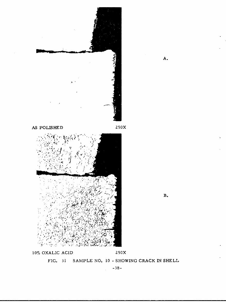
31 Sample No. 10 - Showing Crack in Shell ........ . 38
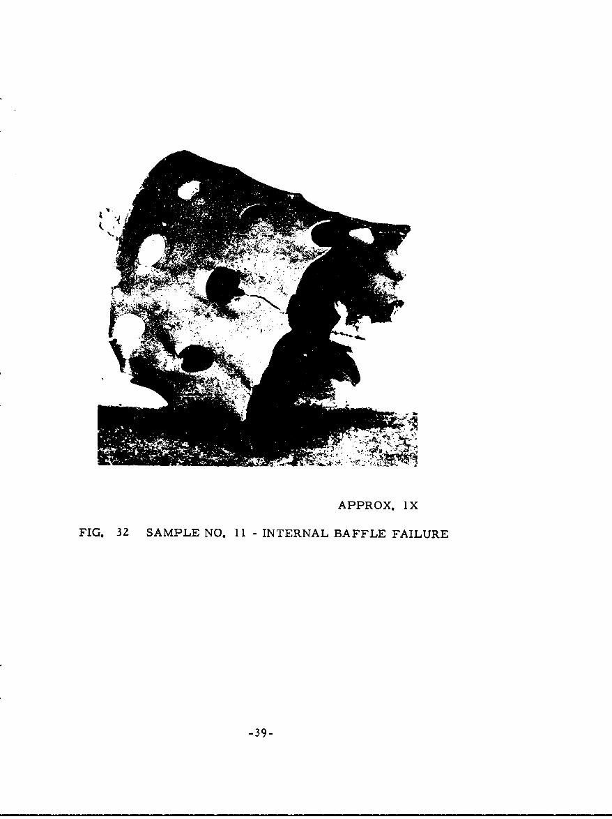
32 Sample No. I I - Internal Baffle Failure . . . # . . . 39
33 Sample No. I I - Showing Heavy Oxidation of Baffle . . 41
34 Sample No. I I - Showing Carbides at Inside Surfaceof Baffle (Top) and Sigma Phase in Grain Boundaries . 41
35 Sample No. 12 - Internal Baffle Failure ..... ........ 42
36 Sample No. 12 - Showing (A) Oxidation at Surfaces and(B) Deeper Penetration at Various Locations on InsideSurface . ......................... 43
37 Sampie No. 12 - Showing Heavier Carburizatior. onOutside Surface of Baffle ..... ............... .... 44
38 Sample No. 12 - Showing (A) Sigma Phase and Carbidesat the Outside Surface and (B) Sigma Phase with MuchLess Carburization at the Inside Surface ............. 45
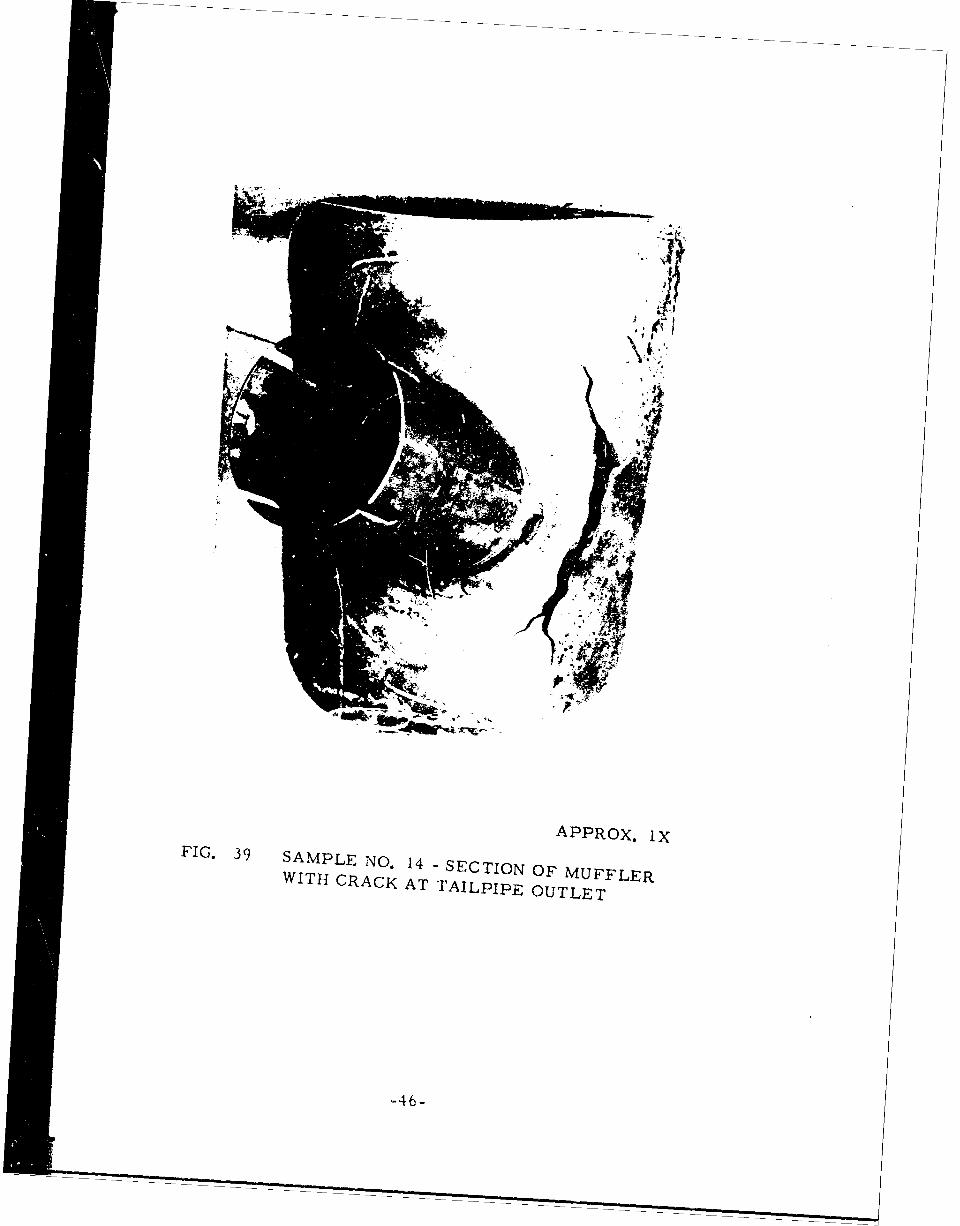
39 Sample No. 14 - Section of Muffler with Crack atTailpipe Outlet . . . . ........... . . . . . . 46
40 Sample No. 14 - Showing Structure at a Location onSide of Tailpipe Opposite to That Which Cracked . . . 48
41 Sample No. 14 - Showing Spot Weld and Course ofCrack in Base Metal ...... .................. .... 48
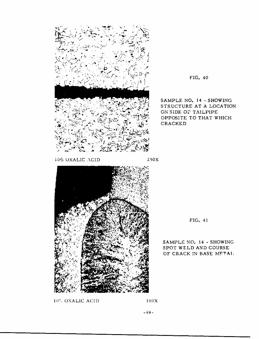
4Z Sample No. 14 - Showing Grain Boundary Precipitateat a Location Near the Spot Weld and the Crack . . . . 49
LIST O0' ILLUSTRATIONS (Continued)
FIGURE PAGE
43 Sample No. 14 - Showing the Structure of a Portionof the Spot Weld and the Base Metal Near the FusionWeld. The Grain Size is Larger than at OtherLocations Examined. The Structure Shows a GrainBoundary Precipitate...... . . . . . ....... 49
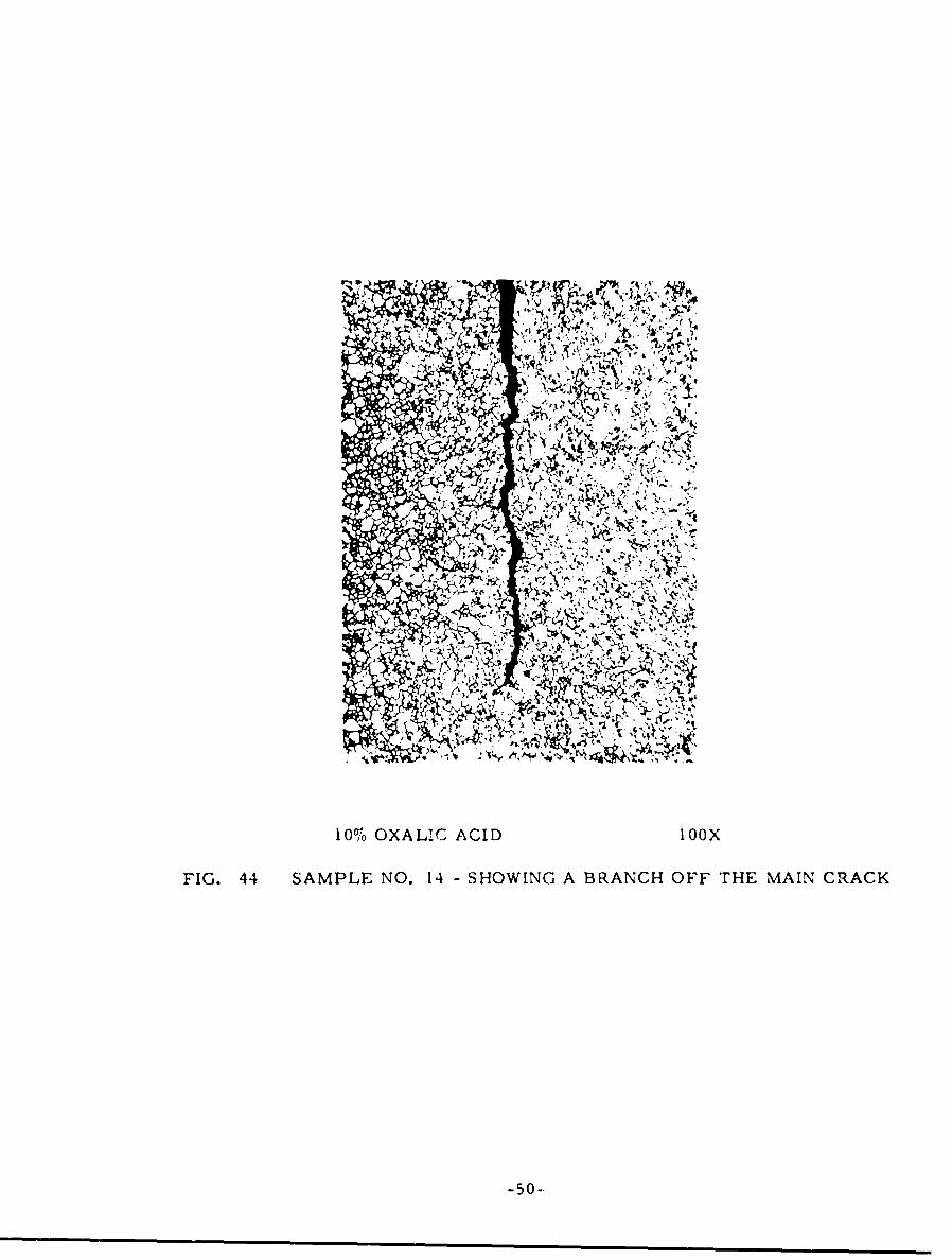
44 Sample No. 14 - Showing a Branch Off the MainCrack . . . .......... . . . . . . . . . . . . . 50
LIST OF TABLES
TABLE PAGE
I Identification of Samples from Aircraft ExhaustSystems .. .. .. .. .. .. .. .. .. .. .. . .. 4
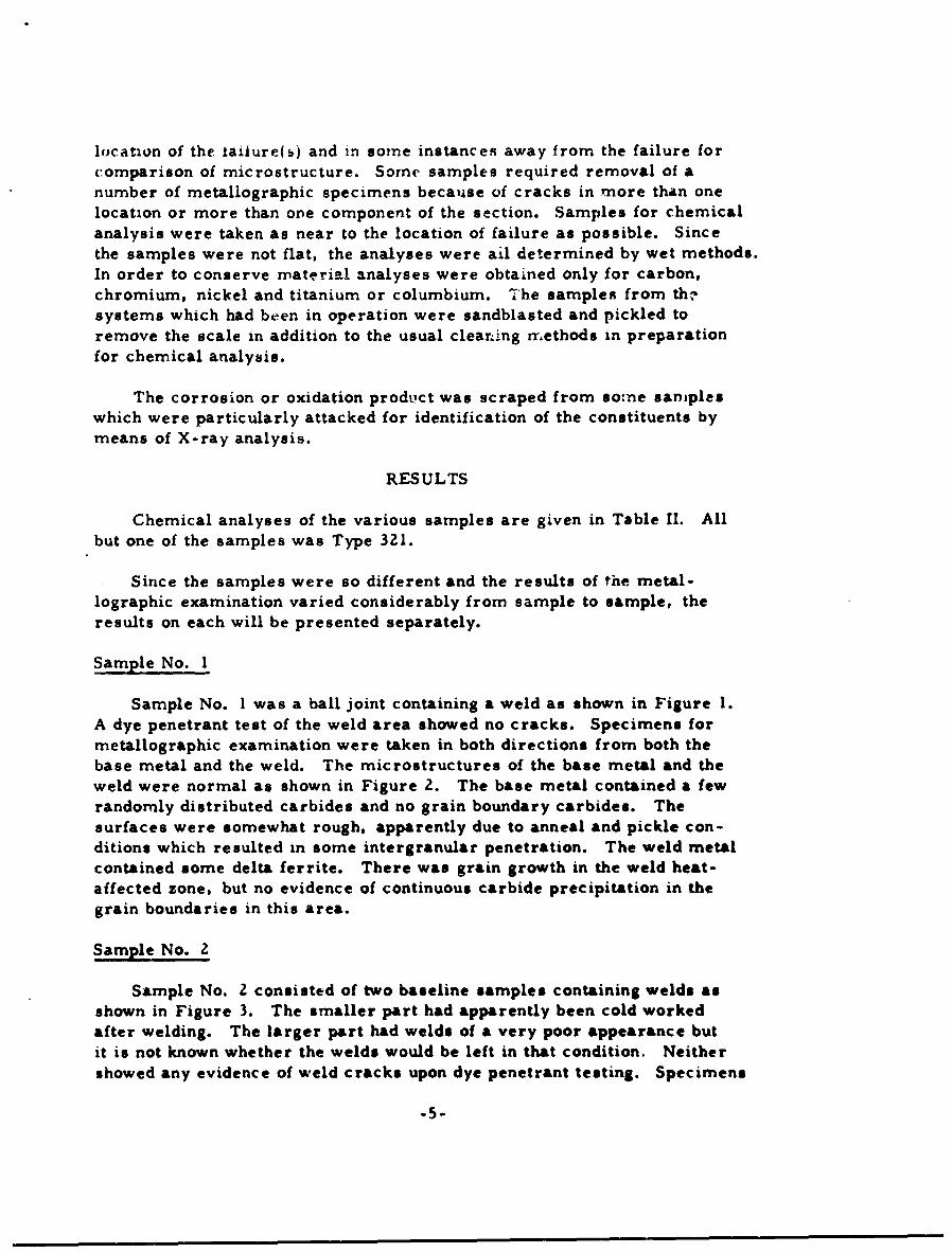
U1 Chemical Analysis of Samples . . ............. 6
vi
FEDERAL AVIATION AGENCY
TECTINICAL REPORT ADY-28
METALLURGICAL EVALUATION OF FAILED AIRCRAFT STAINLESS STEELEXHAUST SYSTEM COMPONENTS
By T. H. McCunn, Allegheny Ludlum Steel Corporation
Summary
A total of twelve samples from small aircraft exhaust sy9tems were investi-gated metallurgically. Three of the samples, referred to as baseline, werefrom new, unused systems. These were examined metallographically forgeneral microstructural characteristics and chemically analyzed. The othersamples were from systems which had failed while in flight operatio.,. Thesesamples were examined tnetallographically and analyzed chemically todetermine the cause(s) of failure. The investigation was supplemented byvisual examination and in some instances identification of the constituentsof the oxidation or corrosion products by X-ray means.
The samples were representative of a number of designs and different typesof failures which have been encountered. Practically all the materials wereAISI Type 321, a titanium-stabilized austenitic stainless steel. Examinationof the baseline samples showed microstructures of the base metal, weldand weld heat-affected zone to be noriral. Four samples failed because ofexcessive oxidation or high temperature corrosion due apparently to unevenflow of gases, resulting in local overheating. carburization. and probablymore rapid attack b', the products of combustion, especially lead compounds.Four other samples from mufflers of similar design and one sample of adifferent design showed fatigue cracks. The failures were attributed toexcessive vibrationa, and/or thermal stresses in the presence of abruptchanges in section size and likely locations for crack initiation.
ViI
INTRODUCTION
Purpose
The investigations of Contract No. FA-NAF-176 were undertaken todetermine the cause(s) of failure of small aircraft exhaust systems. Someof the failures result in a serious safety hazard in that cracks in certain
locations or parts allow the leakage of exhaust fumes to which occupants ofthe aircraft may be exposed.
Background
Initially the investigations were to include samples from (1) new, un-
used systems, (2) new, unused systems which failed after test by vibrationonly, (3) new, unused systems which failed after being operated on the
ground with an aircraft engine in a test bed under simulated flight conditions,and (4) systems which failed while installed in operating aircraft as a resultof actual flight. Because of certain delays samples from only new, unused
systems and systems which failed in operating aircraft have been receivedand examined up to this time. The former are referred to as baseline
samples.
The exhaust systems are fabricated from a stabilized grade of stainlesssteel, mostly AISI Type 321 and sometimes AISI Type 347.
Some Characteristics of Stainless Steels
Stainless steels are broadly classified into two groups according to
composition. The first group is the AISI 400 series or straight chromium
grades which contain chromium as the principal alloy addition. The
crystal structure is body-centered cubic and the materials are magnetic.Within this group some of the grades, such as AISI Types 410 and 420,
are termed martensitic because they are capable of being heat treatedsimilar to plain carbon or low alloy steels to obtain high strength andhardness. The other straight chromium grades, such as AISI Types430 and 446, are termed ferritic and are not heat treatable. The mar-
tensitic types generally contain less chromium than the fertitic types,but there is some overlap depending on the amount of other elements,
especially carbon. The martensitic types can be extended to higherchromium content by increasing the carbon content. Type 440A is anexample. The second group is the AISI 300 series -r chromium-nickel
grades. These steels are austenitic by virtue of the high nickel contrL..
Relatively small amounts of ferrite may be present depending upon the
balance of the chromium and nickel contents and other elements such as
carbon, molybdenum, etc. The crystal structure of austenite is face-
centered cubic. The austenitic steels are nonmagnetic. These steels
-I-
are not heat treatable but can be cold wor':.ed to high strength and hardnesslevels. The chromium and nickel contents vary somewhat according tospecific requirements, but the most common grades, such as AISI Types301 and 304, contain about 18 percent chromium and 8 percent nickel.
The greater oxidation and corrosion resistance of stainless steelscompared to low alloyed steels is due to the presence of chromium.Generally, steels with less than about I 1 percent chromium are not con-sidered as stainless steels. The oxidation resistance increases withchromium content, although not linearly. However, as the chromiumcontent increases, the maximum operating temperature for continuousservice increases from about 1300°F for the IZ percent chromium steelsto 2000 F for 25 percent chromium steels. Similarly, the corrosionresistance to a large number of environments increases with increasingchromium content. The excellent corrosion resistance of the stainlesssteels is generally attributed to a spontaneously formed thin film on thesurface which makes the steels passive. However, stainless steels are-nore passive under oxidizing service conditions and may be attacked quiterapidly under reducing conditions. The presence of nickel in the austeniticgrades increases the resistance of these steels to many kinds of corrosiveenvironments.
Thus, while the oxidation and corrosion resistance of the stainlesssteels is primarily due to the chromium content, nickel increases thecorrosion resistance in certain environments and the addition of molyb-denum may further enhance corrosion resistance for special purposes inthe more aggressive media. Furthermore, the austenitic chromium-nickel steels have higher strength than the straight chromium steels atelevated temperatures and are somewhat more formable and weldable.Therefore, the austenitic grades have been used for aircraft exhaustsystems. However, under conditions which may be present in exhaustsystems the austenitic stainless steels may undergo rapid deterioration.This can be further accelerated by design and fabrication and by micro-structural changes which occur during exposure of these steels totemperatures at which some parts of an aircraft exhaust system operate.
The austenitic stainless steels are subject to carburization undercertain conditions. The carbon combines with the chromium, formingcarbides so that the chromium content of the matrix is decreased. Thedecrease in effective chromium content decreases the oxidation resistance.The oxidation resistance, or high temperature corrosion resistance, isgenerally considered to be decreased in the presence of lead compounds.
The austenitic stainless steels undergo precipitation of chromiumcarbides in the grain loundaries upon heating in the temperature range ofabout 900 to 1500° F. Because of the depletion of chromium near the grain
-Z-
boundaries, the steels are then subject to intergranular attack upon exposureto corrosive environments. In exhaust systems the corrosive substancescan be condensates. Susceptibility to intergranular corrosion can be mini-mized or eliminated by addition of elements such as titanium or columbiumwhich combine with the carbon more readily than chromium. Thesestabilized grades are AISI Type 321 (titanium addition) and AISI Type 347(columbium addition). However, under certain conditions as a result ofextreme heating or welding followed by exposure at sensitizing temperatures,chromium carbides may form in preference to titanium or columbiumcarbides and the steels may be susceptible to intergranular attack. Awell-known example is knife-line attack near welds.
AustenItic stainless steels are also susceptible to stress corrosioncracking, especially in the presence of liquids containing halide ions.Characteristic of the cracks is that they are transgranular and have manybranches. The latter helps to distinguish stress-corrosion cracks fromfatigue cracks which are also transgranular.
A number of references is given in Appendix I for those readersinterested 4n more information on the general characteristics of stainlesssteels. Many of these articles contain references on more specificsubjects.
PROCEDURE
A total of twelve samples were received for evaluation. These wereidentified and described as given in Table I. The samples representedsections from exhaust systems of a number of different designs. Baselinesamples had no apparent connection with the samples from systems whichhad been in service. The relationship of the section received to the entireexhaust system was generally not known at the time the investigation wasbegun.
Each sample was first visually inspected for condition, location offailure, and any other characteristic which might help in the determinationof the cause of failure. Each sample was subjected to simple tests suchas a dye penetrant test of the welds of the baseline samples and responseto a hand magnet. The samples were then photographed in one or morepositions to show the primary characteristics and for future reference.
Each sample was then marked for removal of metallographicspecimens and chemical analysis samples. Since no information on thebaseline samples other than that given in Table I was available, metal-lographic specimens were removed for a general examination of the basemetal and weld structures in both the longitudinal and transverse directions.For the other samples the metallographic specimens were removed at the
-3-
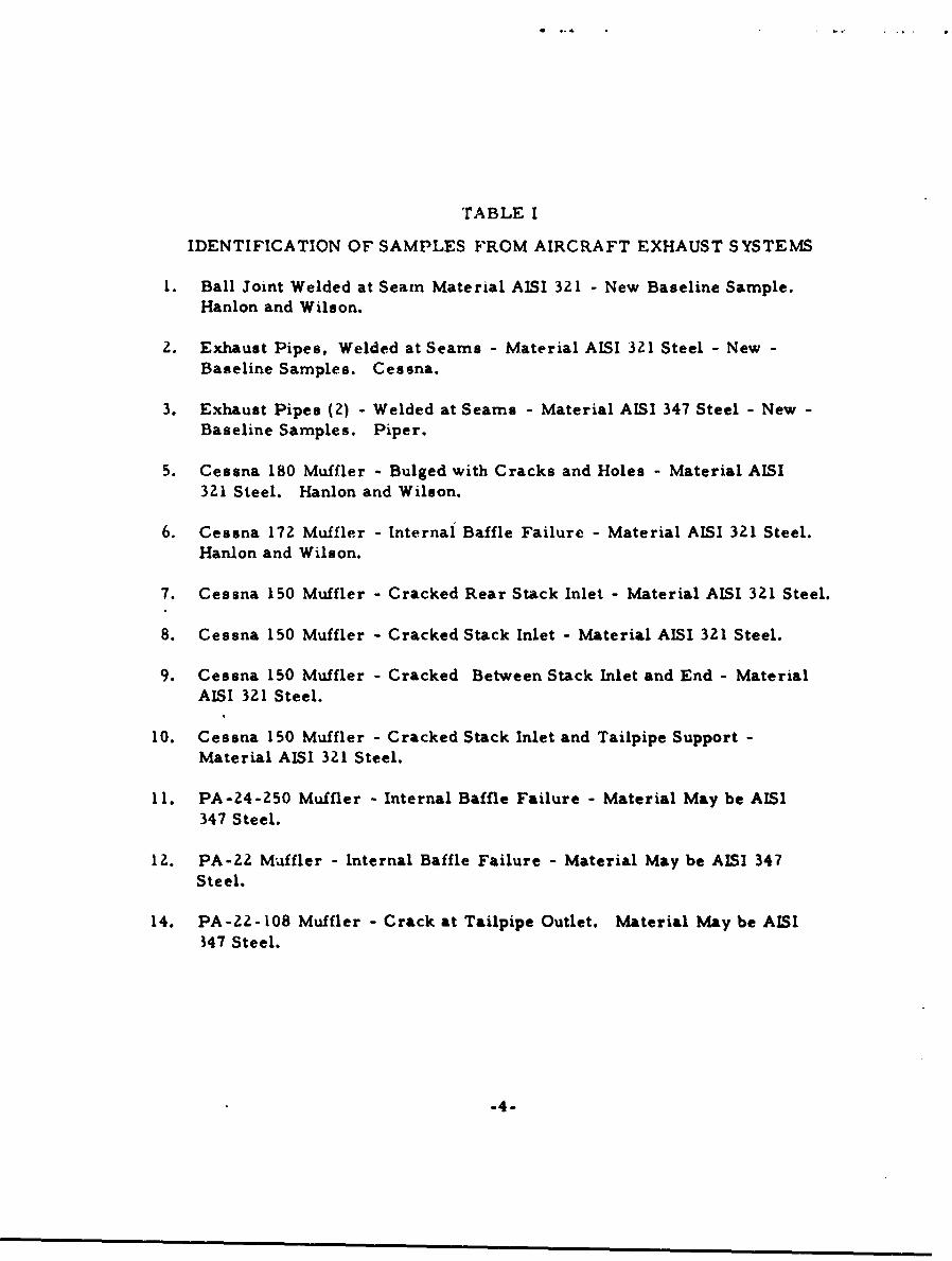
TABLE I
IDENTIFICATION OF SAMPLES FROM AIRCRAFT EXHAUST SYSTEMS
1. Ball Joint Welded at Seam Material AISI 321 - New Baseline Sample.Hanlon and Wilson.
2. Exhaust Pipes, Welded at Seams - Material AISI 321 Steel - New -Baseline Samples. Cessna.
3. Exhaust Pipes (2) - Welded at Seams - Material AISI 347 Steel - New -Baseline Samples. Piper.
5. Cessna 180 Muffler - Bulged with Cracks and Holes - Material AISI321 Steel. Hanlon and Wilson.
6. Cessna 172 Muffler - Internal Baffle Failure - Material AISI 321 Steel.
Hanlon and Wilson.
7. Cessna 150 Muffler - Cracked Rear Stack Inlet - Material AISI 321 Steel.
8. Cessna 150 Muffler - Cracked Stack Inlet - Material AISI 321 Steel.
9. Cessna 150 Muffler - Cracked Between Stack Inlet and End - MaterialAISI 321 Steel.
10. Cessna 150 Muffler - Cracked Stack Inlet and Tailpipe Support -
Material AISI 321 Steel.
11. PA-24-250 Muffler - Internal Baffle Failure - Material May be AISI347 Steel.
12. PA-22 Muffler - Internal Baffle Failure - Material May be AISI 347Steel.
14. PA-22-108 Muffler - Crack at Tailpipe Outlet. Material May be AISI347 Steel.
-4-
location of the tailure(s) and in some instances away from the failure forcomparison of microstructure. Some samples required removal of anumber of metallographic specimens because of cracks in more than onelocation or more than one component of the section. Samples for chemicalanalysis were taken as near to the location of failure as possible. Sincethe samples were not flat, the analyses were ail determined by wet methods.In order to conserve material analyses were obtained only for carbon,chromium, nickel and titanium or columbium. The samples from th-systems which had been in operation were sandblasted and pickled toremove the scale in addition to the usual cleaning rrmethods in preparationfor chemical analysis.
The corrosion or oxidation product was scraped from so:me sanmpleswhich were particularly attacked for identification of the constituents bymeans of X-ray analysis.
RESULTS
Chemical analyses of the various samples are given in Table II. Allbut one of the samples was Type 321.
Since the samples were so different and the results of the metal-
lographic examination varied considerably from sample to sample, theresults on each will be presented separately.
Sample No. I
Sample No. I was a ball joint containing a weld as shown in Figure 1.A dye penetrant test of the weld area showed no cracks. Specimens formetallographic examination were taken in both directions from both thebase metal and the weld. The microstructures of the base metal and theweld were normal as shown in Figure 2. The base metal contained a few
randomly distributed carbides and no grain boundary carbides. Thesurfaces were somewhat rough, apparently due to anneal and pickle con-ditions which resulted in some intergranular penetration. The weld metalcontained some delta ferrite. There was grain growth in the weld heat-affected zone, but no evidence of continuous carbide precipitation in thegrain boundaries in this area.
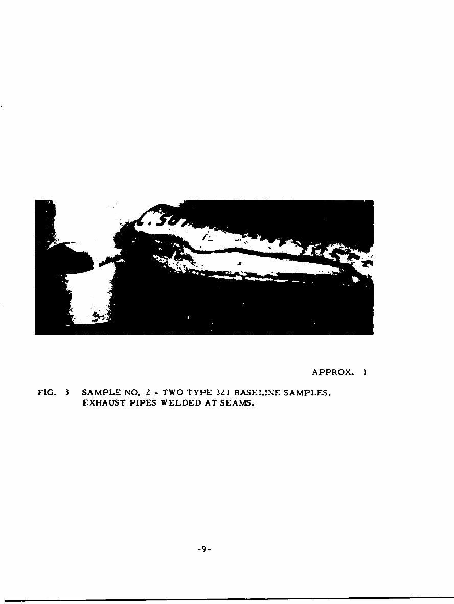
Sample No. 2
Sample No. 2 consisted of two baseline samples containing welds asshown in Figure 3. The smaller part had apparently been cold workedafter welding. The larger part had welds of a very poor appearance butit is not known whether the welds would be left in that condition. Neithershowed any evidence of weld cracks upon dye penetrant testing. Specimens
-5-
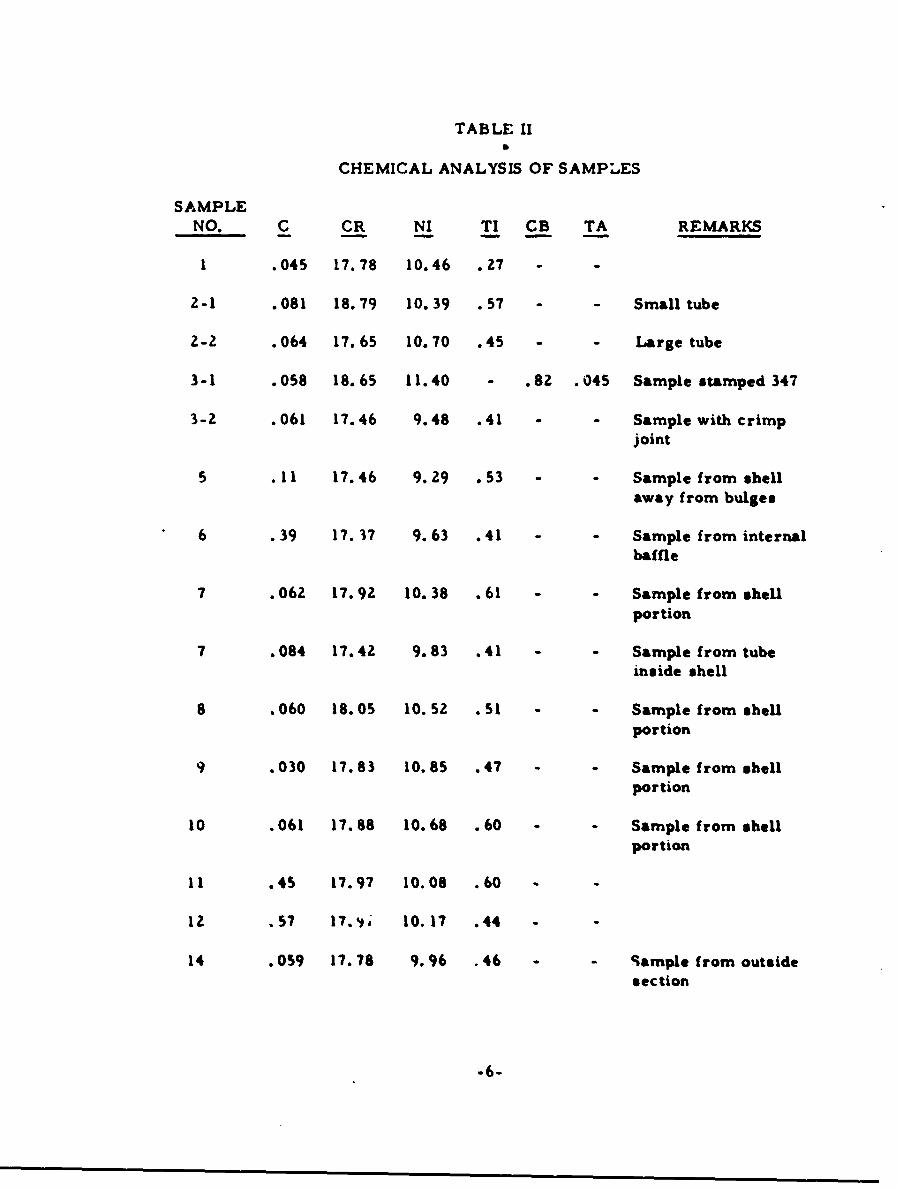
TABLE II
CHEMICAL ANALYSIS OF SAMPLES
SAMPLE
NO. C CR NI TI CB TA REMARKS
I .045 17.78 10.46 .27 - -
2-1 .081 18.79 10.39 .57 - - Small tube
2-2 .064 17.65 10.70 .45 - Large tube
3-1 .058 18.65 11.40 - .82 .045 Sample stamped 347
3-2 .061 17.46 9.48 .41 - Sample with crimpjoint
5 .11 17.46 9.29 .53 - Sample from shellaway from bulges
6 .39 17. 37 9.63 .41 - Sample from internalbaffle
7 .062 17.92 10. 38 .61 - - Sample from shell
portion
7 .084 17.42 9.83 .41 - - Sample from tubeinside shell
8 .060 18.05 10.52 .51 - - Sample from shellportion
9 .030 17.83 10.85 .47 - Sample from shellportion
10 .061 17.88 10.68 .60 - - Sample from shellportion
I I .45 17.97 10.08 .60 -
12 .57 17.,18 10.17 .44 -
14 .059 17.78 9.96 .46 - Sample from outsidesection
-6-

APPROX. IX
FIG. 1 SAMPLE NO. I - TYPE 321 BASELINE SAMPLE.BALL JOINT WELDED AT SEAM.
-7-
A.
BASE METAL AT BOTTOM, HAVINGTITANIUM CARBONITRIDES. WELDMETAL AT TOP.
0
AS POLISHED 1O0X
B.
BASE METAL AT BOTTOM ANDWELD METAL AT TOP, SHOWINGSOME GRAIN GROWTH IN HEAT-AFFECTED ZONE.
~A,
I0o OXALIC ACID 0OOX
FIG. .• SAMPLE NO. 1. alHOWING NORMAL STRUCTURE
-8-
APPROX. I
FIG. 3 SAMPLE NO. 2 - TWO TYPE 321 BASELINE SAMPLES.EXHAUST PIPES WELDED AT SEAMS.
-9-
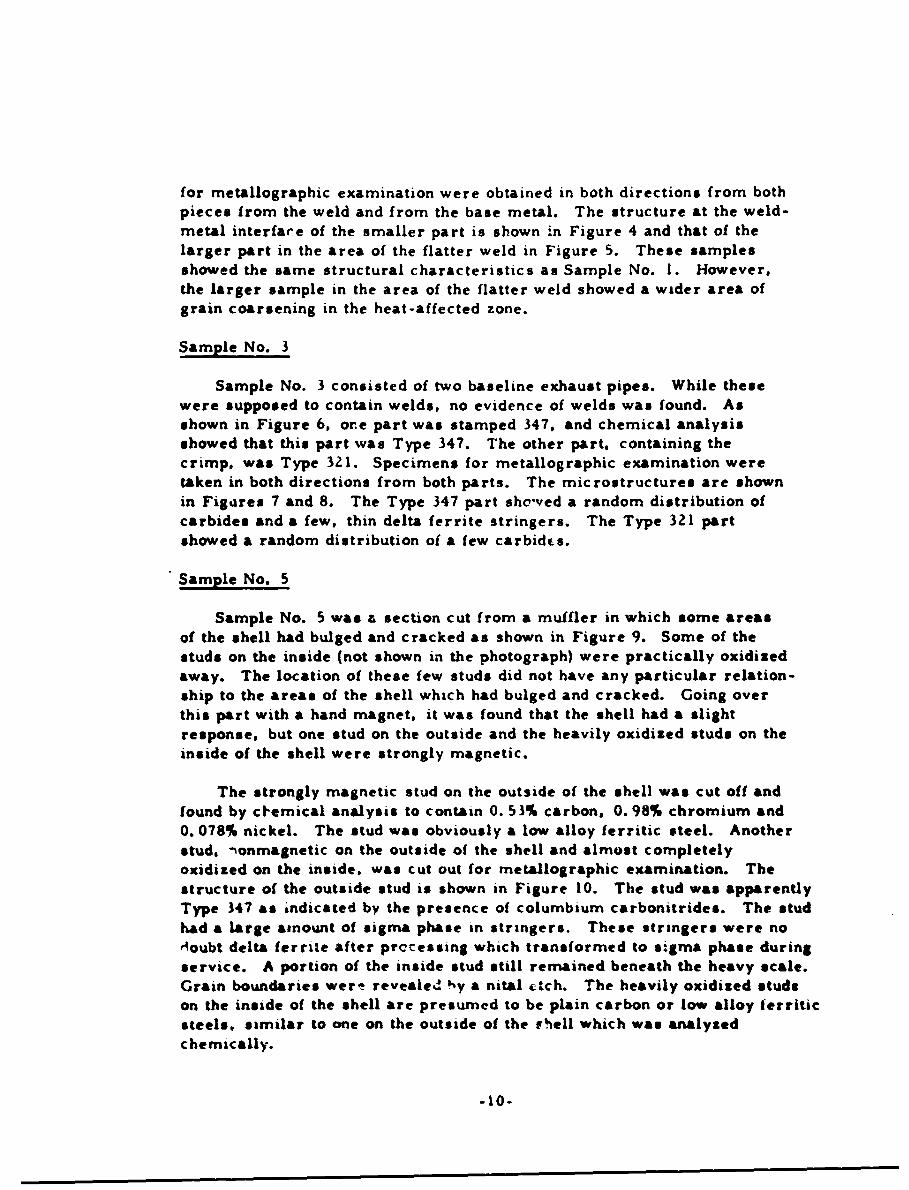
for metallographic examination were obtained in both directions from bothpieces from the weld and from the base metal. The structure at the weld-metal interface of the smaller part is shown in Figure 4 and that of the
larger part in the area of the flatter weld in Figure 5. These samplesshowed the same structural characteristics as Sample No. 1. However,the larger sample in the area of the flatter weld showed a wider area of
grain coarsening in the heat-affected zone.
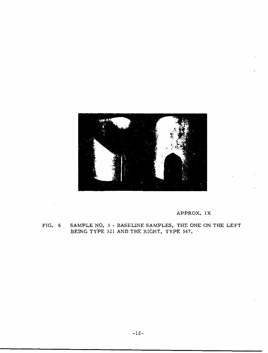
Sample No. 3
Sample No. 3 consisted of two baseline exhaust pipes. While thesewere supposed to contain welds, no evidence of welds was found. Asshown in Figure 6, ore part was stamped 347, and chemical analysisshowed that this part was Type 347. The other part, containing thecrimp. was Type 321. Specimens for metallographic examination weretaken in both directions from both parts. The microstructures are shownin Figures 7 and 8. The Type 347 part showed a random distribution ofcarbides and a few, thin delta ferrite stringers. The Type 321 partshowed a random distribution of a few carbidcs.
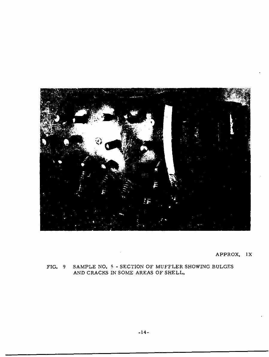
Sample No. 5
Sample No. 5 was a section cut from a muffler in which some areasof the shell had bulged and cracked as shown in Figure 9. Some of thestuds on the inside (not shown in the photograph) were practically oxidizedaway. The location of these few studs did not have any particular relation-ship to the areas of the shell which had bulged and cracked. Going overthis part with a hand magnet, it was found that the shell had a slight
response, but one stud on the outside and the heavily oxidized studs on theinside of the shell were strongly magnetic.
The strongly magnetic stud on the outside of the shell was cut off andfound by ctemical analysis to contain 0. 53% carbon, 0.98% chromium and0. 078% nickel. The stud was obviously a low alloy ferritic steel. Anotherstud. nonmagnetic on the outside of the shell and almost completelyoxidized on the inside, was cut out for metallographic examination. The
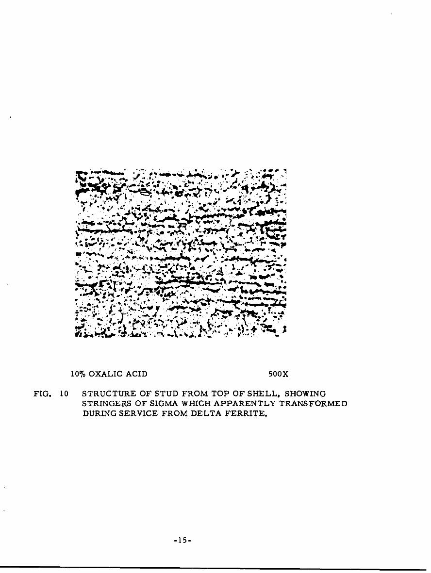
structure of the outside stud is shown in Figure 10. The stud was apparentlyType 347 as indicated by the presence of columbium carbonitrides. The studhad a large amount of sigma phase in stringers. These stringers were no,Ioubt delta ferrLte after prccessing which transformed to sigma phase duringservice. A portion of the inside stud still remained beneath the heavy scale.
Grain boundaries wer- revealed Iy a nital ctch. The heavily oxidized studson the inside of the shell are presumed to be plain carbon or low alloy ferriticsteels, similar to one on the outside of the rFhell which was analyzedchemically.
-10-
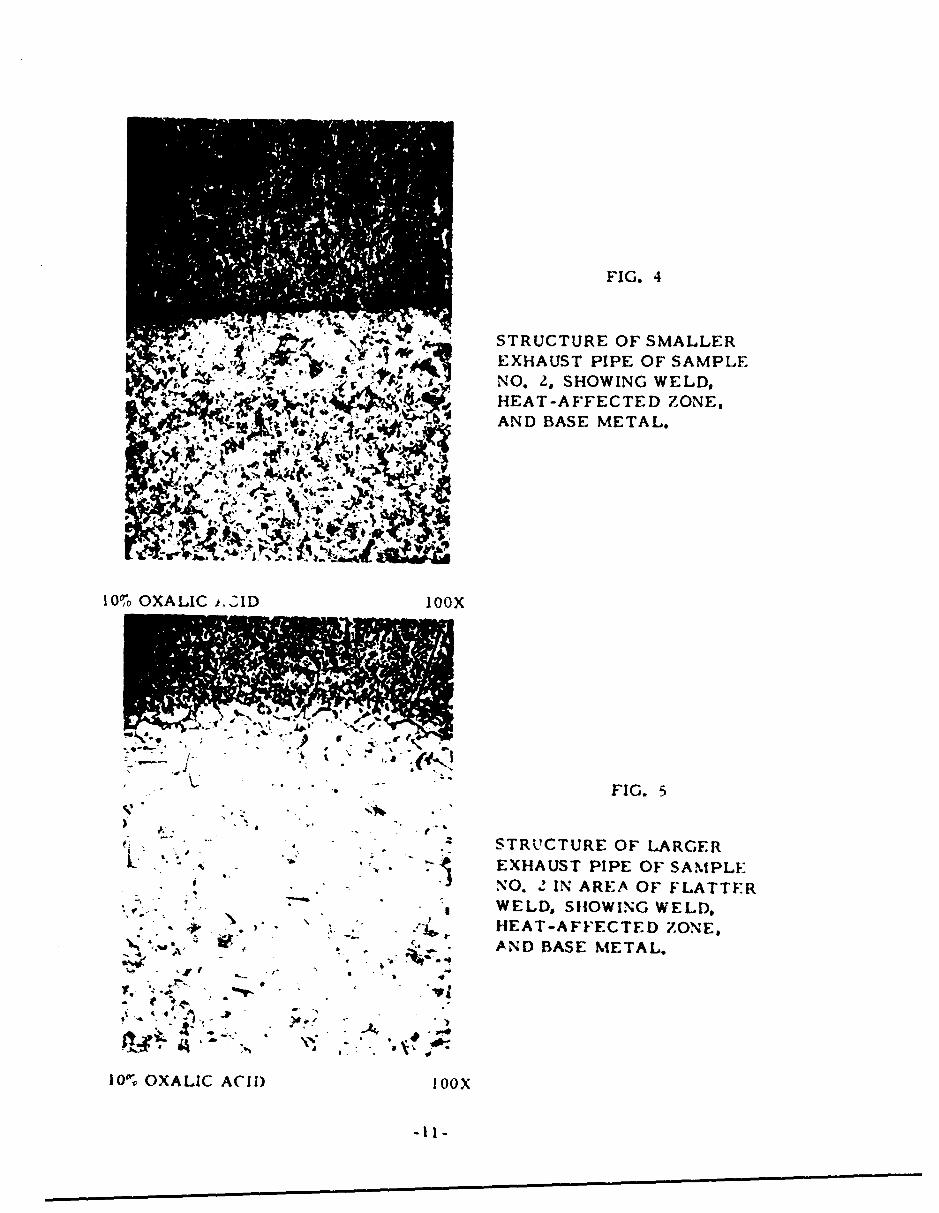
FIG. 4
STRUCTURE OF SMALLER= ~ EXHAUST PIPE OF SAMPLE
. r ~NO. 2, SHOWING WELD,WA~ H EAT-AFFECTED ZONES
~b ~Sr ~AND BASE METAL.
101o OXALIC t.OýID bOoX
FIG.5
STRU'CTURE OF LARGER.. EXHAUST PIPE OF SAIMPLE
* NO. 2 IN AREA OF FLATTFRWELD, SHOWING WELD.
* * * .HEAT-AFFECTED ZONE,"* ~ AND BASE METAL.
~I I
APPROX. lX
FIG. 6 SAMPLE NO. 3 - BASELINE SAMPLES, THE ONE ON THE LEFTBEING TYPE 321 AND THE RIGHT, TYPE 347.
-12-
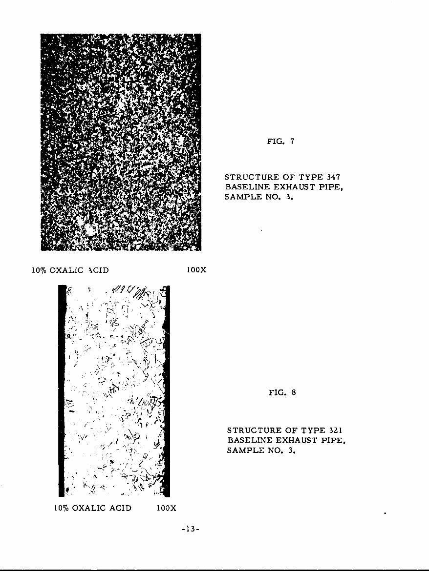
FIG. 7
STRUCTURE OF TYPE 347BASELINE EXHAUST PIPE,SAMPLE NO. 3.
10% OXALIC XCID looX
)f Z7
"I ,FIG. 8S.
"'• - / ." -, .\ /:•y
SFIG..
S-STRUCTURE OF TYPE 321
BASELINE EXHAUST PIPE,SAMPLE NO. 3.
10% OXALIC ACID looX
-13-
APPROX. IX
FIG. 9 SAMPLE NO. 5 - SECTION OF MUFFLER SHOWING BULGESAND CRACKS IN SOME AREAS OF SHELL.
-14-
VI t4 .I. ' -" ... ,.• ++•+, ';- i .• ."' " ' . -
to.
.. . .... b 4 ,k_+ . i. .JII•bbI IA-h. -. ?.
.4,I., 1*0STRUCT E..- O STUD FROM TO. PHO.. O. .. E,, * ,,
10%ORAICGR ACI SIM5HIHAPRETYTANFRE
DURING SERVICE FROM DELTA FERRITE.
-15-
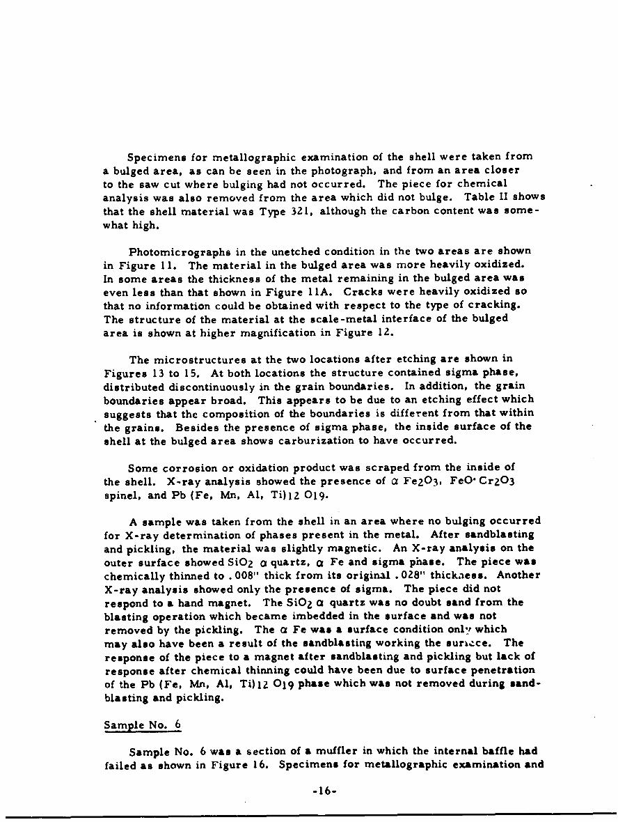
Specimens for metallographic examination of the shell were taken froma bulged area, as can be seen in the photograph, and from an area closerto the saw cut where bulging had not occurred. The piece for chemicalanalysis was also removed from the area which did not bulge. Table II showsthat the shell material was Type 321, although the carbon content was some-what high.
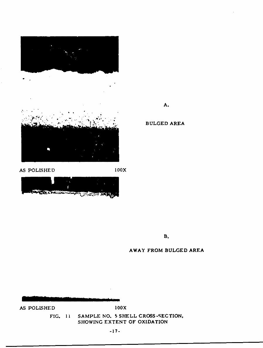
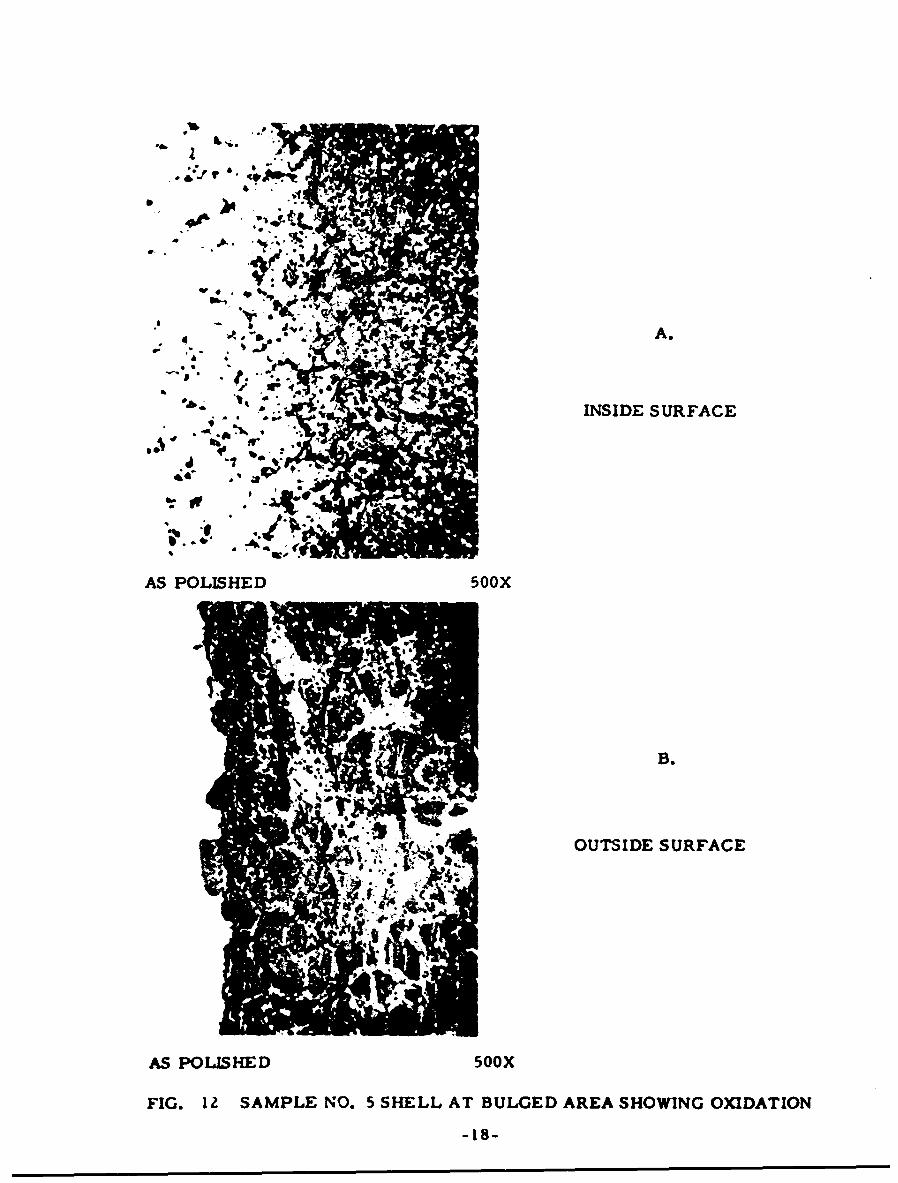
Photomicrographs in the unetched condition in the two areas are shownin Figure 11. The material in the bulged area was more heavily oxidized.In some areas the thickness of the metal remaining in the bulged area waseven less than that shown in Figure 11A. Cracks were heavily oxidized sothat no information could be obtained with respect to the type of cracking.The structure of the material at the scale-metal interface of the bulgedarea is shown at higher magnification in Figure 12.
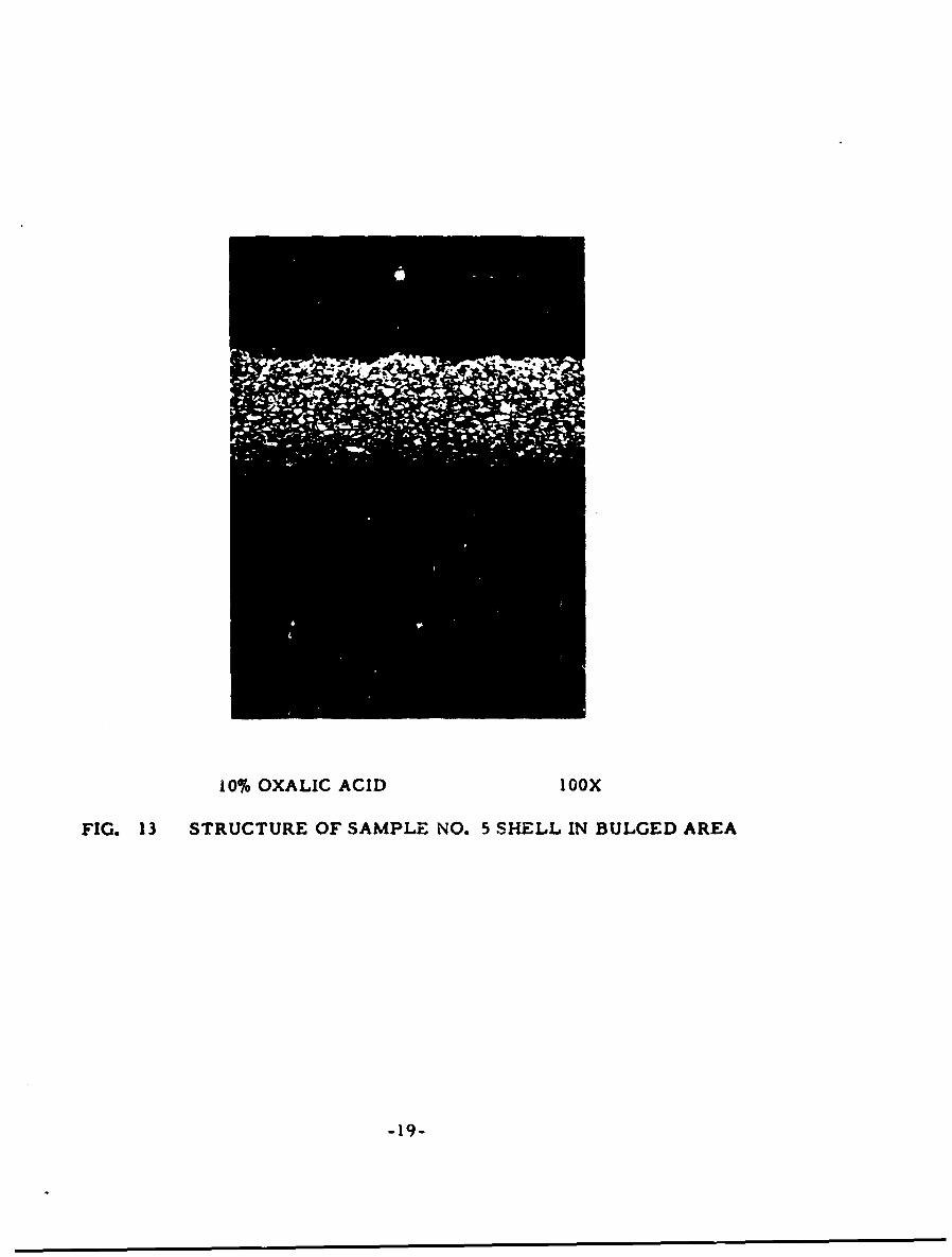
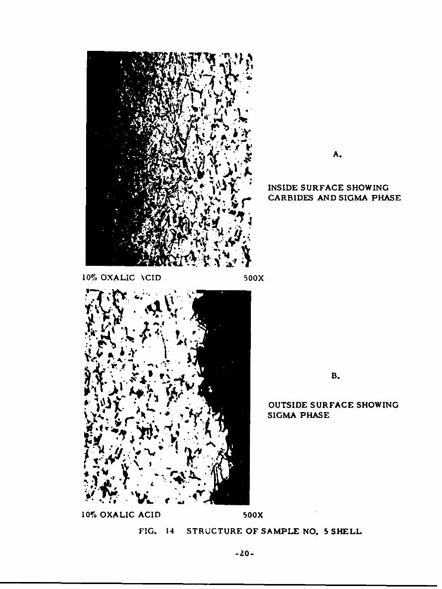
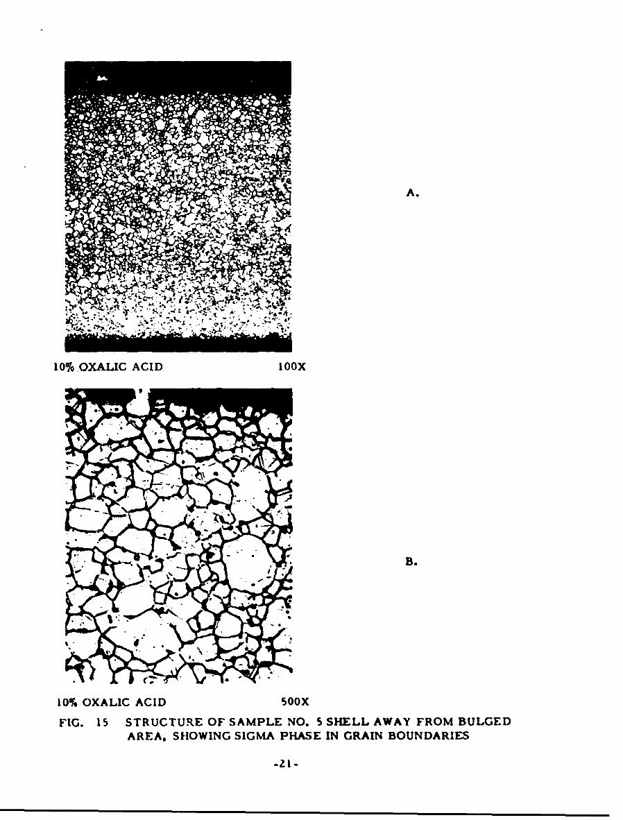
The microstructures at the two locations after etching are shown inFigures 13 to 15. At both locations the structure contained sigma phase,distributed discontinuously in the grain boundaries. In addition, the grainboundaries appear broad. This appears to be due to an etching effect whichsuggests that the composition of the boundaries is different from that withinthe grains. Besides the presence of sigma phase, the inside surface of theshell at the bulged area shows carburization to have occurred.
Some corrosion or oxidation product was scraped from the inside ofthe shell. X-ray analysis showed the presence of a Fe203, FeO" Cr203spinel, and Pb (Fe, Mn, Al, Ti)12 019.
A sample was taken from the shell in an area where no bulging occurredfor X-ray determination of phases present in the metal. After sandblastingand pickling, the material was slightly magnetic. An X-ray analysis on theouter surface showed SiO 2 a quartz, a Fe and sigma phase. The piece waschemically thinned to . 008" thick from its original . 028" thickiess. AnotherX-ray analysis showed only the presence of sigma. The piece did notrespond to a hand magnet. The SiO2 a quartz was no doubt sand from theblasting operation which became imbedded in the surface and was notremoved by the pickling. The a Fe was a surface condition onl:r whichmay also have been a result of the sandblasting working the suriace. Theresponse of the piece to a magnet after sandblasting and pickling but lack ofresponse after chemical thinning could have been due to surface penetrationof the Pb (Fe, Mn, Al, Ti)12 019 phase which was not removed during sand-blasting and pickling.
Sample No. 6
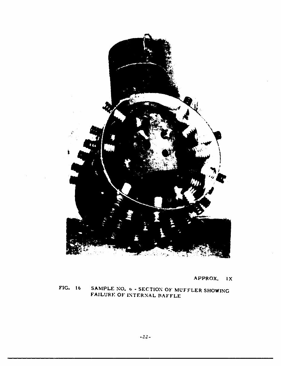
Sample No. 6 was a section of a muffler in which the internal baffle hadfailed as shown in Figure 16. Specimens for metallographic examination and
-16-
A.
"BULGED AREA
AS POLISHED 1OOX
B.
AWAY FROM BULGED AREA
AS POLISHED 1OOX
FIG. 11 SAMPLE NO. 5 SHELL CROSS-SECTION,SHOWING EXTENT OF OXIDATION
-17-
AA
INSIDE SURFACE
b.r
AS POLISHED 500X
B.
OUTSIDE SURFACE
AS POLISHED 500X
FIG. IZ SAMPLE NO. 5 SHELL AT BULGED AREA SHOWING OXIDATION
-18-
10% OXALIC ACID 0ooX
FIG. 13 STRUCTURE OF SAMPLE NO. 5 SHELL IN BULGED AREA
-'9-
A.': " t'j fr
A.
INSIDE SURFACE SHOWING
, yCARBIDES AND SIGMA PHASE
~: :
10% OXALIC \CID 50OX
i I -%4 B
,b."o . , . * • °.',ph :1;: ,- B."•' "
S! !~
.. . OUTSIDE SURFACE SHOWING• '. SIGMA PHASE
iri
in, IG 4 .C . SML NO. 5 SHELL
10% OXALIC ACID S00X
FIG. 14 STRUCTURE OF SAMPLE NO. 5 SHELL
-20-
A.
1001 OXALIC ACID I OOX
B.
10% OXALIC ACID 500X
FIG. 15 STRUCTURE OF SAMPLE NO. S SHELL AWAY FROM BULGEDAREA, SHOWING SIGMA PHASE IN GRAIN BOUNDARIES
-21-
le
APPROX. IX
FIG. 16 SAMPLE NO. b -SECTION OF MUFFLER SHOWINGFAILUTRE OF INTERNAL BAFFLE
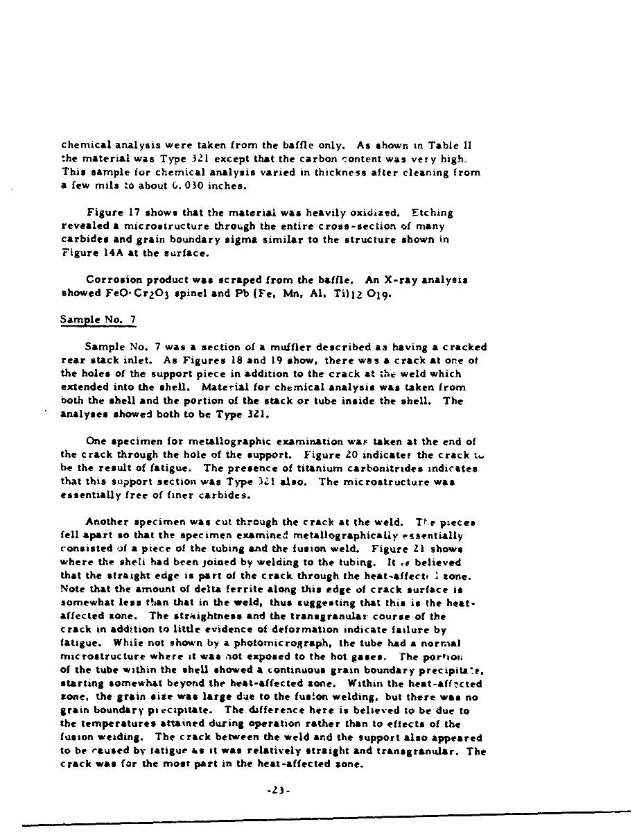
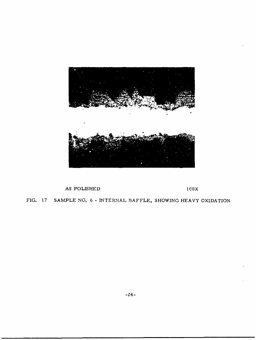
chemical analysis were taken from the baffle only. As shown in Table 11:he material was Type 321 except that the carbon content was very high.This sample for chemical analysis varied in thickness after cleaning froma few mils to about (. 030 inches.
Figure 17 shows that the material was heavily oxidized. Etchingrevealed a microstructure through the entire cross-section of manycarbides and grain boundary sigma similar to the structure shown inFigure 14A at the surface.
Corrosion product was scraped from the baffle. An X-ray analysisshowed FeO.Cr 2O 3 spinel and Pb (Fe, Mn, Al. Ti)12 019.
Sample No. 7
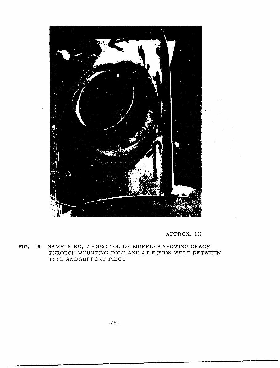
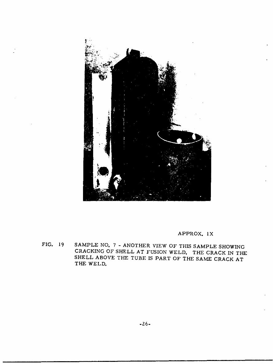
Sample No. 7 was a section of a mulfler described as having a crackedrear stack inlet. As Figures 18 and 19 show. there was a crack at ore ofthe holes of the support piece in addition to the crack at the weld whichextended into the shell. Material for chemical analysis was taken fromboth the shell and the portion of the stack or tube inside the shell. Theanalyses showed both to be Type 321.
One specimen for metallographic examination waF taken at the end ofthe crack through the hole of the support. Figure 20 indicateF the crack w,be the result of fatigue. The presence of titanium carbonitrides indicatesthat this support section was Type 361 also. The microstructure wasessentially free of finer carbides.
Another specimen was cut through the crack at the weld. VTe piecesfell apart so that the specimen examined me tallographicaliy essentiallyconsisted of a piece of the tubing and the fusion weld. Figure 21 showswhere the shell had been joined by welding to the tubing. It E, believedthat the straight edge is part of the crack through the heat-affecto 3 zone.Note that the amount of delta ferrite along this edge of crack surface issomewhat less t.an that in the weld, thus suggesting that this is the heat-affected zone. The straightness and the transgranular course of thecrack in addition to little evidence of deformation indicate failure byfatigue. While not shown by a photomicrograph. the tube had a norm.almicrostructure where it was not exposed to the hot gases. The portiotaof the tube within the shell showed a continuous grain boundary precipita&e,starting somewhut beyond the heat-affected zone. Within the heat-affictedzone. the grain size was large due to the fusion welding, but there was nograin boundary precipitate. The dafference here is believed to be due tothe temperatures attained during operation rather than to effects of thefusion weiding. The crack between the weld and the support also appearedto be r'aused by fatigue as it was relatively straight and transgranular. Thecrack was for the most part in the heat-affected zone.
-23-
AS POLISHED IOOX
FIG. 17 SAMPLE NO. 6 - INTERNAL BAFFLE, SHOWING HEAVY OXIDATION
APPROX. lX
FIG. 18 SAMPLE NO. 7 - SECTION OF MUFFLER SHOWING CRACKTHROUGH MOUNTING HOLE AND AT FUSION WELD BETWEENTUBE AND SUPPORT PIECE
-25-
APPROX. 1X
FIG. 19 SAMPLE NO. 7 - ANOTHER VIEW OF THIS SAMPLE SHOWINGCRACKING OF SHELL AT FUSION WELD. THE CRACK IN THESHELL ABOVE THE TUBE IS PART OF THE SAME CRACK ATTHE WELD.
-26-

~ 7 ~FIG. 20
SAMPL NO 7 HWN
Z/ HOLE IN SUPOR PIEC
SAMPL NO 7 - SHWN
FUIO WEDWER HL
WA ONDT H UE
10%~ OXALIC ACI 250XIG 2
-27
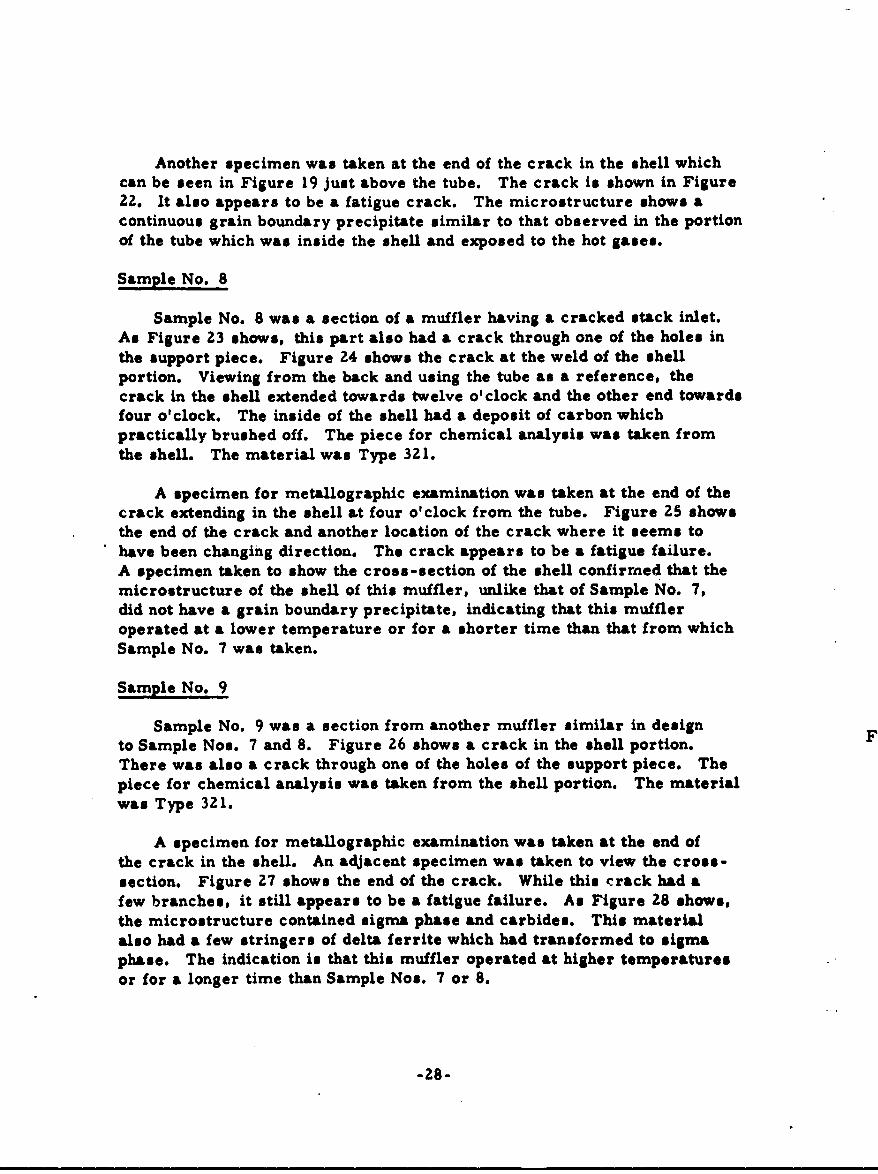
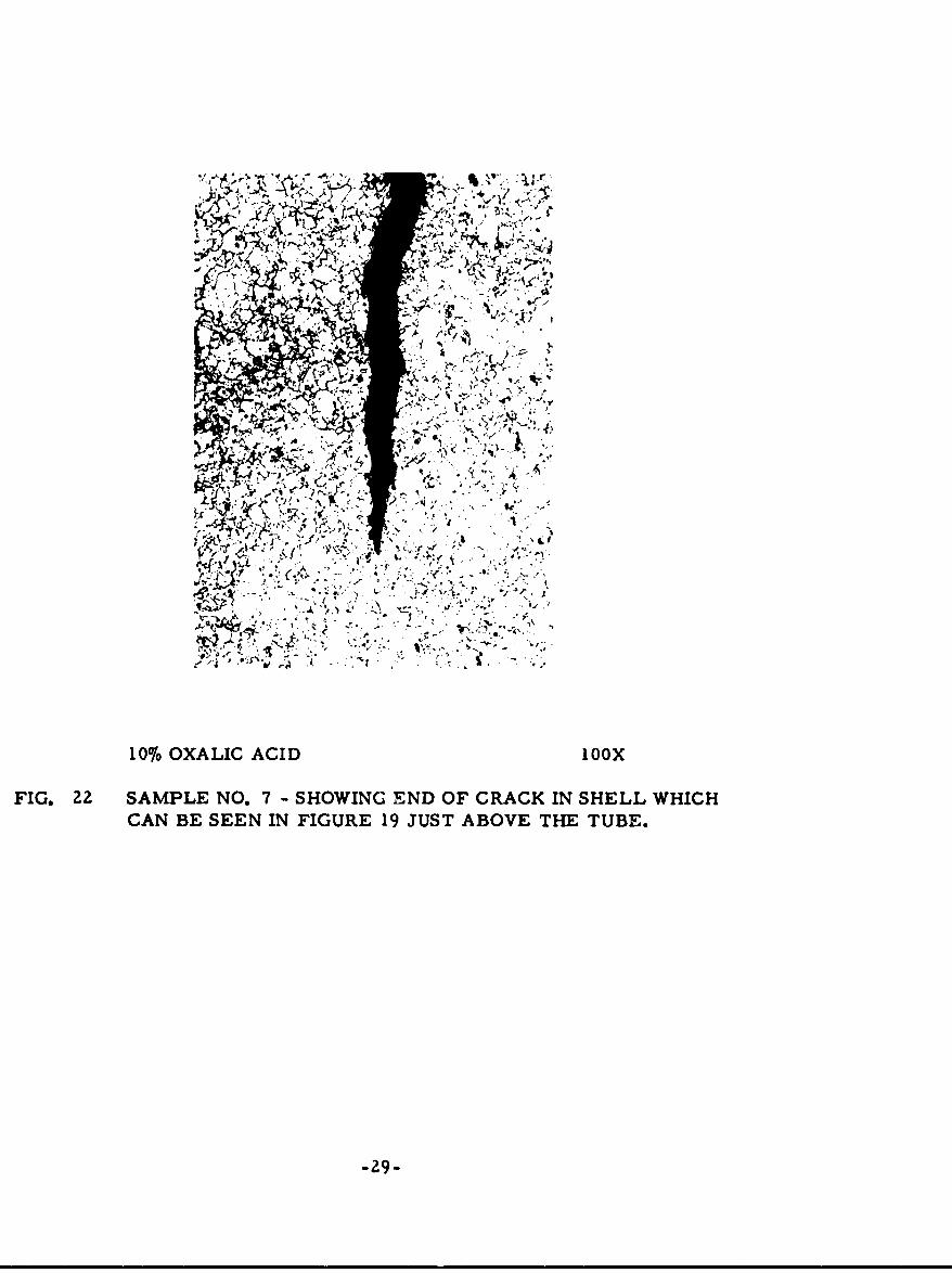
Another specimen was taken at the end of the crack in the shell whichcan be seen in Figure 19 just above the tube. The crack is shown in Figure22. It also appears to be a fatigue crack. The microstructure shows acontinuous grain boundary precipitate similar to that observed in the portionof the tube which was inside the shell and exposed to the hot gases.
Sample No. 8
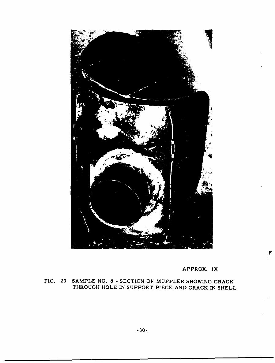
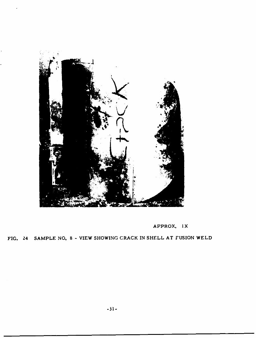
Sample No. 8 was a section of a muffler having a cracked stack inlet.As Figure 23 shows, this part also had a crack through one of the holes inthe support piece. Figure 24 shows the crack at the weld of the shellportion. Viewing from the back and using the tube as a reference, thecrack in the shell extended towards twelve o' clock and the other end towardsfour o'clock. The inside of the shell had a deposit of carbon whichpractically brushed off. The piece for chemical analysis was taken fromthe shell. The material was Type 321.
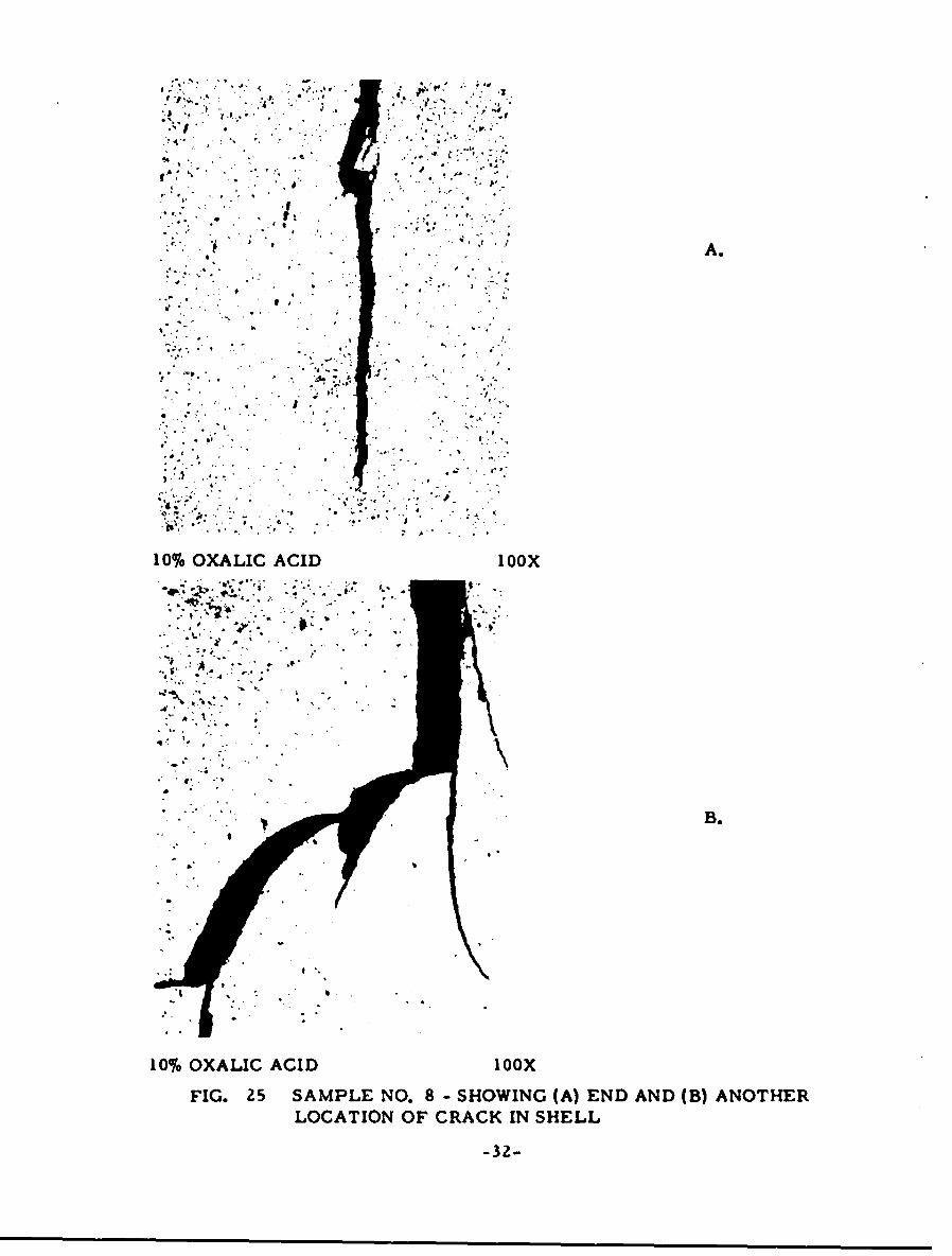
A specimen for metallographic examination was taken at the end of thecrack extending in the shell at four o'clock from the tube. Figure 25 showsthe end of the crack and another location of the crack where it seems tohave been changing direction. The crack appears to be a fatigue failure.A specimen taken to show the cross-section of the shell confirmed that themicrostructure of the shell of this muffler, unlike that of Sample No. 7,did not have a grain boundary precipitate, indicating that this muffleroperated at a lower temperature or for a shorter time than that from whichSample No. 7 was taken.
Sample No. 9
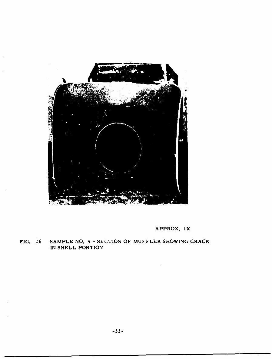
Sample No. 9 was a section from another muffler similar in design Fto Sample Nos. 7 and 8. Figure 26 shows a crack in the shell portion.There was also a crack through one of the holes of the support piece. Thepiece for chemical analysis was taken from the shell portion. The materialwas Type 321.
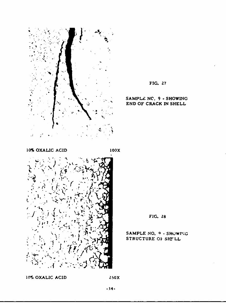
A specimen for metallographic examination was taken at the end ofthe crack in the shell. An adjacent specimen was taken to view the cross-section. Figure 27 shows the end of the crack. While this crack had afew branches, it still appears to be a fatigue failure. As Figure 28 shows,the microstructure contained sigma phase and carbides. This materialalso had a few stringers of delta ferrite which had transformed to sigmaphase. The indication is that this muffler operated at higher temperaturesor for a longer time than Sample Nos. 7 or 8.
-28-
kJ-r. LZ.I-~~. -C *Z
X4'.
107o4~4 OX LCA I 4
FIG.22 AMPE N. 7- SOWIG ED O CAK NHLLWHC
* 29
F
APPROX. IX
FIG. 23 SAMPLE NO. 8 - SECTION OF MUFFLER SHOWING CRACKTHROUGH HOLE IN SUPPORT PIECE AND CRACK IN SHELL
-30-
APRX I
FIG. 24 SAMPLE NO. 8 -VIEW SHOWING CRACK IN SHELL AT FUSION WELD
-31-
.. 'A.
I~ lt
* A.
FIG .5 SAMPLE NO4 HWN A N N B NTE
LOATO OF CRC-NHL
a -32-
APPROX. IX
FIG. 26 SAMPLE NO. 9 - SECTION OF MUFFLER SHOWING CRACKIN SHELL PORTION
-33-
-- 27,.'
I L
'.,-. - FIG. 27
.1SAMPLE NO. 9SHOWING
,-. .'" *A END OF CRACK IN SHELL• o . -
10% OXALIC ACID 10oX
. ,-34
~ -- •-"e •"/ ,€
-, * -j
•lI. .; --.. I
.- . -. .-. ..
10 OXAL~~IC CDZO
Sample No. 10
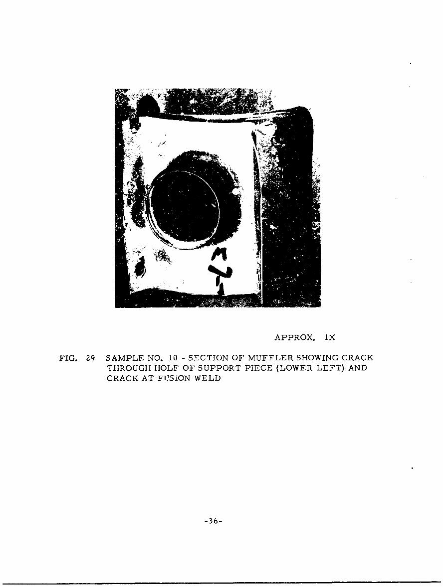
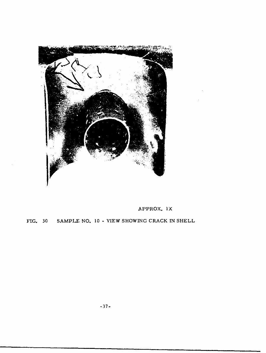
Sample No. 10 was a portion of anocher muffler similar in design toSample Nos. 7, 8 and 9. As Figure -29 shows, this part had a crackthrough one of the holes of the support piece and a crack at the fusionweld in the support piece. The crack extended into the shell portion asshown in Figure 30. The piece for chemical analysis was taken from
the shell. The material was Type 321.
Since a specimen for metallographic examination to vi.w the end ofthe crack was difficult to obtain because of the curved surfaces, aspecimen was taken through the weld perpenoicular to ýhe plane of thecrack in the shell. This specimen included portions of the tube, the
support piece, and the shell. After the sample vas polished, the crackthrough the shell extended all the way through the cross-section in theplane being viewed. This is sho,- n irn Figure 31 by the relative displace-ment of the two pieces.
Examination of this specimen showed a myriad of microstructures.First of all, the microstructures of the weld, the tube where it was outsidethe shell, and the support piece appeared normal. Similar to Sample No. 7,the s tructure of the portion of the tube within the shell had a continuous
grain boundary network of carbides so'rting beyond the heat-affected zone,apparently hecause of different temperatures attained during operation. Inthe shell portion at the crack the microstructure showed a continuous grainboundary precipitate near the surfaces, but not near midthicknevs. Themicrostructurc in Figure 31B shows this characteristic at the outsifesurface of the shell. Note that the surface shows some attack and thatanother short crack had started. There was a similar crack to a shallowerdepth on the outside surface but on the other side of the main crack. Thesecracks are transoranular and appear to be fatigue cracks. The micro-structure of the shell in the heat-affected tone showed the usual largegrain size but the grain boundary precipitate did not appear until near the
unaffected base metal.
Sample No. 11
Sample No. I 1 was an internal baffle failure. Figure 32 shows thebaffle which was heavily oxidized and distorted and contained cracksespecially at the holes. A piec- for chemical analysis was obtained. Thematerial was Type U1. but the carbon content was high as shown in
Table II.
-35-
APPROX. 1X
FIG. 29 SAMPLE NO. 10 - SECTION OF MUFFLER SHOWING CRACKTHROUGH HOLF OF SUPPORT PIECE (LOWER LEFT) AND
CRACK AT FUSION WELD
-36-
APPROX. lX
FIG. 30 SAMPLE NO. 10 - VIEW SHOWING CRACK IN SHELL
-37-
A.
AS POLISHED 2 50X
10 OXLI ACD 5
-- 38
APPROX. IX
FIG. 32 SAMPLE NO. 11 - INTERNAL BAFFLE FAILURE
-39-
Specimens for metallographic examination were taken in areas ofvarious amounts of distortion. Figure 33 shows heavy oxidation and atendency towards intergranular oxidation at the metal-heavy scaleinterface. Thicknesses of the specimens varied considerably due tothe amount of oxidation involved. Figure 34 shows the microstructureat one surface. The structure contains many carbides and sigma phase.The sigma phase was present throughout the cross-section of allspecimens examined. The carbides were present at both surfaces of allspecimens. Where material was thinned considerably many carbideswere present throughout the cross-section.
Some oxidation product was scraped from the baffle. X-rayanalysis showed Pb (Fe, Mn, Al, Ti)l2 019 and a possible trace ofFeO- Cr20 3 spinel.
Sample No. 12
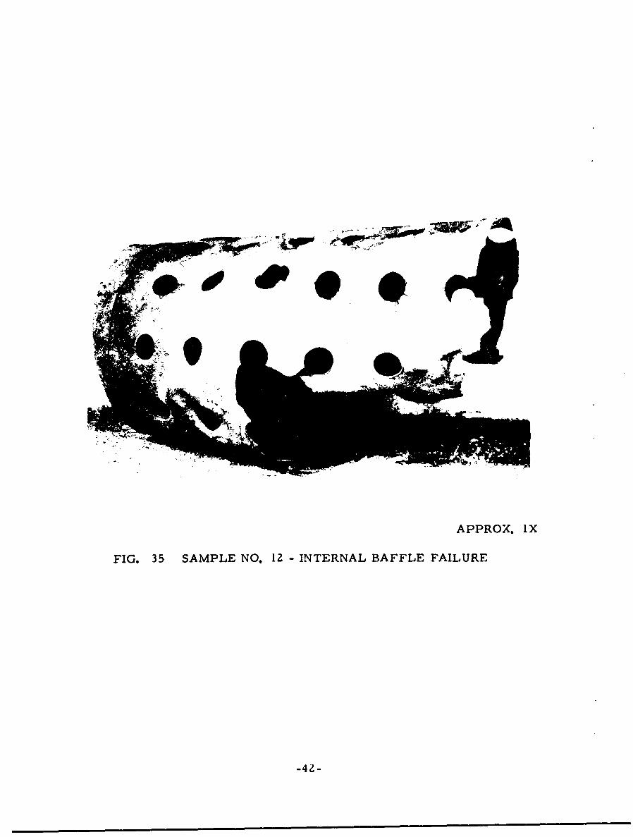
Sample No. 12 was also an internal baffle which had failed. Figure35 shows, like Sample No. 11, that the baffle was distorted and con-tained cracks especially at the holes. Chemical analysis showed thematerial to be Type 321, but the carbon content was high.
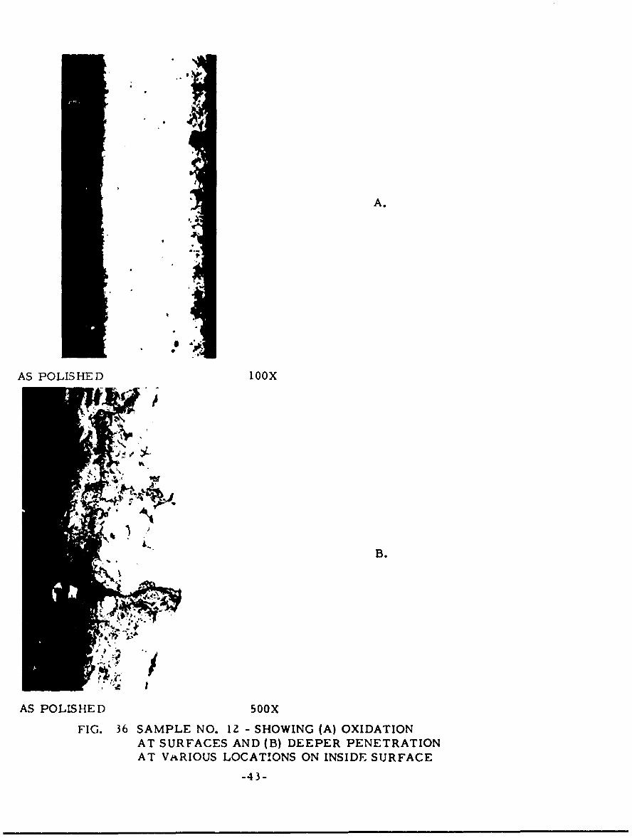
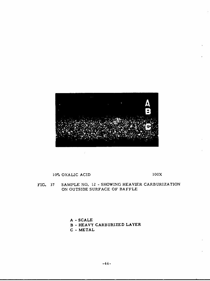
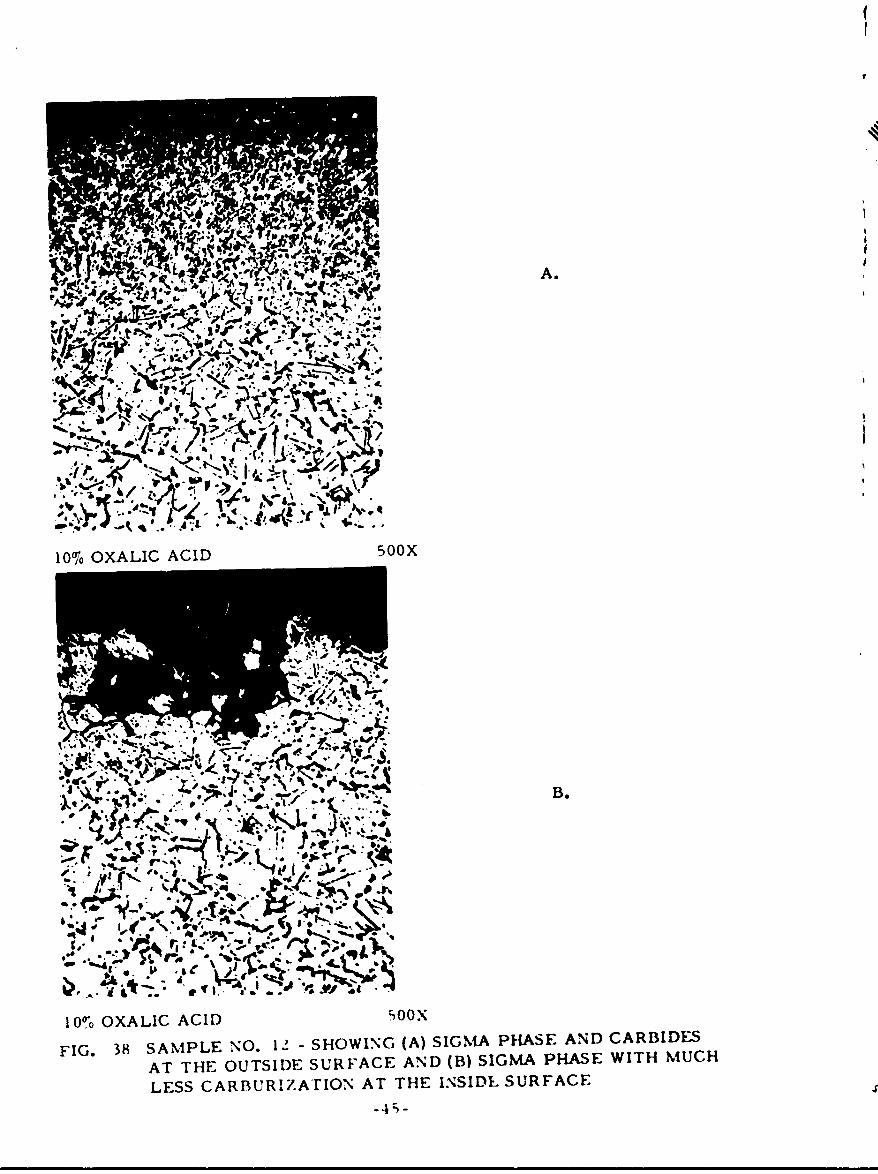
Specimens for metallographic examination were taken at only onelocation. Figure 36 shows the heavy oxidation. In addition, the insidesurface showed deeper penetration at various locations along the surface.Figures 37 and 38 show that the carburization was more prevalent on theoutside surface. Figure 38 shows the presence of sigma phase in thegrain boundaries. The sigma phase was present throughout the cross-section.
Some oxidation product was scraped from the baffle and X-rayanalysis showed the presence of a Fe203, FeO" Cr203 spinel, and Pb(Fe, Mn, Al, Ti)12 019.
Sample No. 14
Sample No. 14 was a section of a muffler which had cracked at thetailpipe outlet as shown in Figure 39. This part had a collar around thestack opening spot-welded on the back. The lip of the collar can be seeninside the tube and a section of the collar can be seen where the crack isopen. The collar was joined to the cracked part by iwo concentric ringsof spot welds. The crack tended to circumvent the spot welds in the outerconcentric ring. A piece for chemical analysis was cut from the part whichcracked. The material was Type 321.
-40-
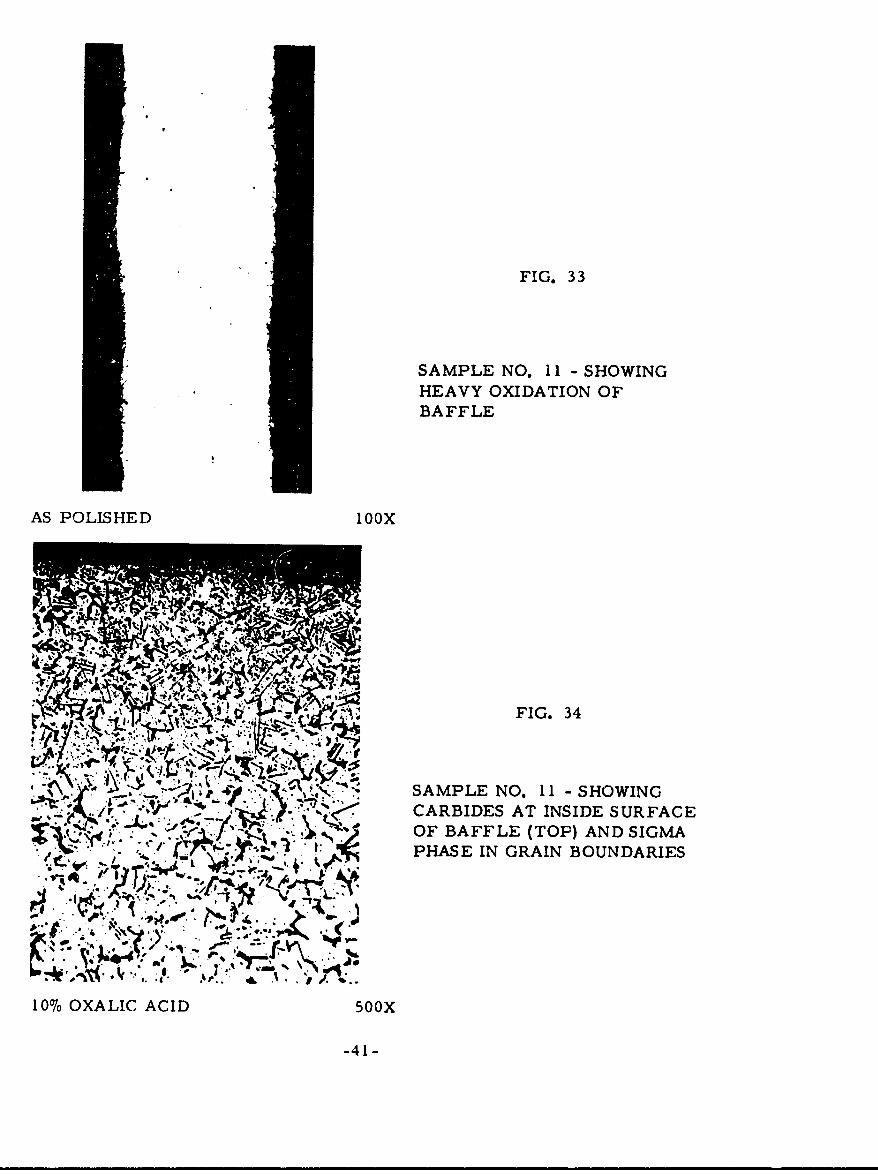
FIG. 33
SAMPLE NO. II - SHOWINGHEAVY OXIDATION OFBAFFLE
AS POLISHED 10OX
SFIG. 34
e\'" SAMPLE NO. 11 - SHOWING
CARBIDES AT INSIDE SURFACE" .OF BAFFLE (TOP) AND SIGMA
PHASE IN GRAIN BOUNDARIES
rl . . , 4. • 4
10% OXALIC ACID 500X
-41-
APPROX. lX
FIG. 35 SAMPLE NO. 12 - INTERNAL BAFFLE FAILURE
-42 -
A.
AS POLISHED 5OOX
A•
-43-
i£
10% OXALIC ACID 1O0X
FIG. 37 SAMPLE NO. 12 = SHOWING HEAVIER CARBURIZATIONON OUTSIDE SURFACE OF BAFFLE
A - SCALE
B - HEAVY CARBURIZED LAYER
C - METAL
-44-
, " tf,'f,
, -. , . .. . • , . -. .r . . , ,
ArL A.
. -;.
* ... o.: ,....L .
aft46,
I~z~-,(_, . j-- -.
-. '. - ,, , ..- .,L
10% OXALIC ACID 500X
. SOA . 1IM
A T: t OEA
-4f,
I~~X~ O~ XLC CDsoFIG. 38 S ILE NO. I HWN ()SGA HS NDCRIE
AT TH USDESRAE N B IGAPAE IHMC
LESCRUIAINATTEISD UFC
APPROX.lXFIG. 39 SAMPLE NO. 14 -SECTION OF MUFFLERWITH- CRACK AT TAILPIPE OUTLET
-46-
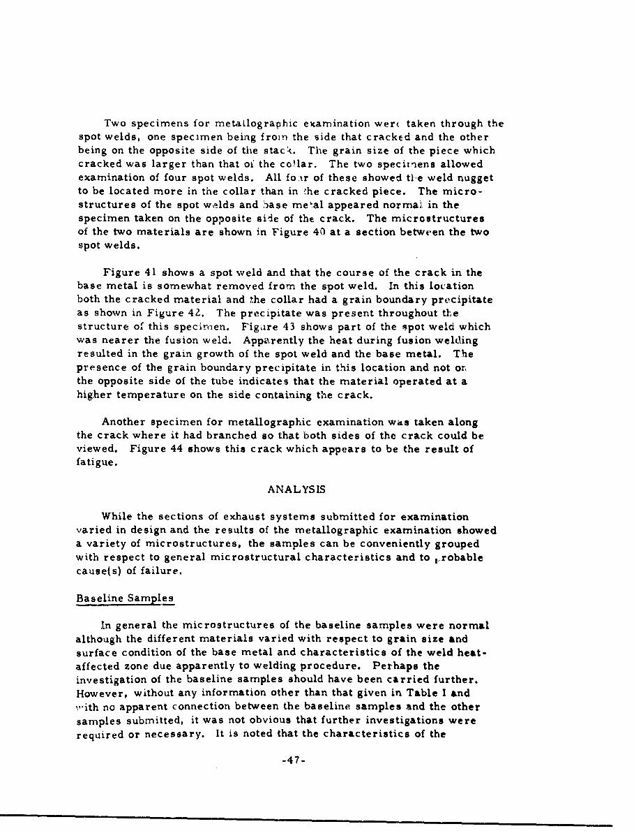
Two specimens for metaklographic examination were taken through thespot welds, one specimen being fromn the side that cracked and the otherbeing on the opposite side of the stack. The grain size of the piece whichcracked was larger than that of the co!lar. The two specitmens allowedexamination of four spot welds. All fo ir of these showed tle weld nuggetto be located more in the collar than in ýhe cracked piece. The micro-structures of the spot welds and base me'al appeared norma,• in thespecimen taken on the opposite siie of the crack. The microstructuresof the two materials are shown in Figure 40 at a section between the twospot welds.
Figure 41 shows a spot weld and that the course of the crack in thebase metal is somewhat removed from the spot weld. In this locationboth the cracked material and the collar had a grain boundary pre'cipitateas shown in Figure 42. The precipitate was present throughout thxestructure of this specirmen. Figaire 43 shows part of the spot weld whichwas nearer the fusion weld. Apparently the heat during fusion weldingresulted in the grain growth of the spot weld and the base metal. Thepresence of the grain boundary precipitate in this location and not or,the opposite side of the tube indicates that the material operated at ahigher temperature on the side containing the crack.
Another specimen for metallographic examination was taken alongthe crack where it had branched so that both sides of the crack could beviewed. Figure 44 shows this crack which appears to be the result offatigue.
ANALYSIS
While the sections of exhaust systems submitted for examinationvaried in design and the results of the metallographic examination showeda variety of microstructures, the samples can be conveniently groupedwith respect to general microstructural characteristics and to -robable
cause(s) of failure.
Baseline Samples
In general the microstructures of the baseline samples were normal
although the different materials varied with respect to grain size andsurface condition of the base metal and characteristics of the weld heat-affected zone due apparently to welding procedure. Perhaps theinvestigation of the baseline samples should have been carried further.However, without any information other than that given in Table I and,,ith no apparent connection between the baseline samples and the other
samples submitted, it was not obvious that further investigations were
required or necessary. It is noted that the characteristics of the
-47-
r, , FI .4
SAMPLE NO. 14 -SHOWING
STRUCTURE AT A LOCATION
ON SIDE Or TAILPIPEOPPOSITE TO THAT WHICH
IV,'.~4 ~ ~ CRACKED
i Ozl OXALIC ACID 250X
FIG. 41
SAMPLE NO. 14 -SHOWING
~ SPOT WELD AND COURSEOF CRACK IN BASE METAL.
1O',)XALIC AC 11) IOOX
-48-
,- %!/ýt4~
FIG. 42
SAMPLE NO. 14 - SHOWING GRAIN0 •"BOUNDARY PRECIPITATE AT A
4 LOCATION NEARTHE SPOT WELD
AND THE CRACK.
10% OXALIC ACID 250X
( . . . " I ""FIG. 43
4 SAMPLE NO. 14 SHOWING THE
' ' ,.. ,:,STRUCTURE OF A PORTION OF•" ",. *: - " ,..."THE SPOT WELD AND THE BASE
. - 5,, . :' "METAL NEAR THE FUSION WELD.\ ' " i•THE GRAIN SIZE IS LARGER THAN
: • iBOUNDARY PRECIPITATE.
10'7 OXALIC ACID 100X
-49-
A 1.
' -l
10% OXALIC ACID I Qox
FIG. 44 SAMPLE NO. 14 - SHOWING A BRANCH OFF THE MAIN CRACK
-50-
occurrence of grain growth and the lack of continuous grain boundarycarbides in the weld heat-affected zones of the baseline samples weresimilar to those observed :-i the examination of the samples which hadbeen in operation, provided that the temperature of operation did notresult in carbide precipitation.
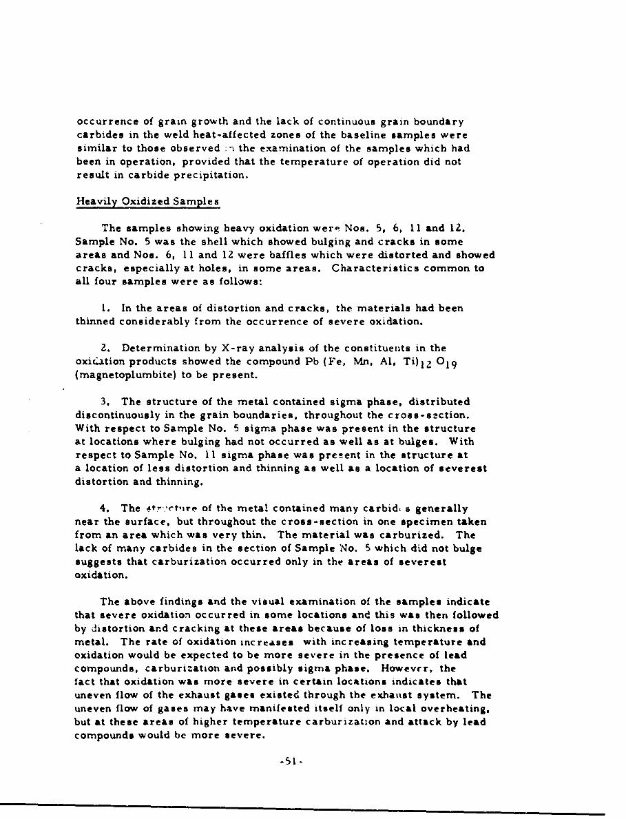
Heavily Oxidized Samples
The samples showing heavy oxidation were Nos. 5, 6, 11 and 12.Sample No. 5 was the shell which showed bulging and cracks in someareas and Nos. 6, 11 and 12 were baffles which were distorted and showedcracks, especially at holes, in some areas. Characteristics common toall four samples were as follows:
I. In the areas of distortion and cracks, the materials had beenthinned considerably from the occurrence of severe oxidation.
2. Determination by X-ray analysis of the constituents in theoxicdation products showed the compound Pb (Fe, Mn, Al, Ti) 1 2 019(magnetoplumbite) to be present.
3. The structure of the metal contained sigma phase, distributeddiscontinuously in the grain boundaries, throughout the cross-s.ction.With respect to Sample No. 5 sigma phase was present in the structureat locations where bulging had not occurred as well as at bulges. Withrespect to Sample No. II sigma phase was pre!!ent in the structure ata location of less distortion and thinning as well as a location of severestdistortion and thinning.
4. The 4t0 "t'ire of the metal contained many carbid, s generallynear the surface, but throughout the cross-section in one specimen takenfrom an area which was very thin. The material was carburized. Thelack of many carbides in the section of Sample No. 5 which did not bulgesuggests that carburization occurred only in the areas of severestoxidation.
The above findings and the visual examination of the samples indicatethat severe oxidation occurred in some locations and this was then followedby distortion and cracking at these areas because of loss in thickness ofmetal. The rate of oxidation increases with increasing temperature andoxidation would be expected to be more severe in the presence of leadcompounds, carburization and possibly sigma phase. However. thefact that oxidation was more severe in certain locations indicates thatuneven flow of the exhaust gases existed through the exhatust system. Theuneven flow of gases may have manifested itself only in local overheating.but at these areas of higher temperature carburization and attack by leadcompounds would be more severe.
-51 -
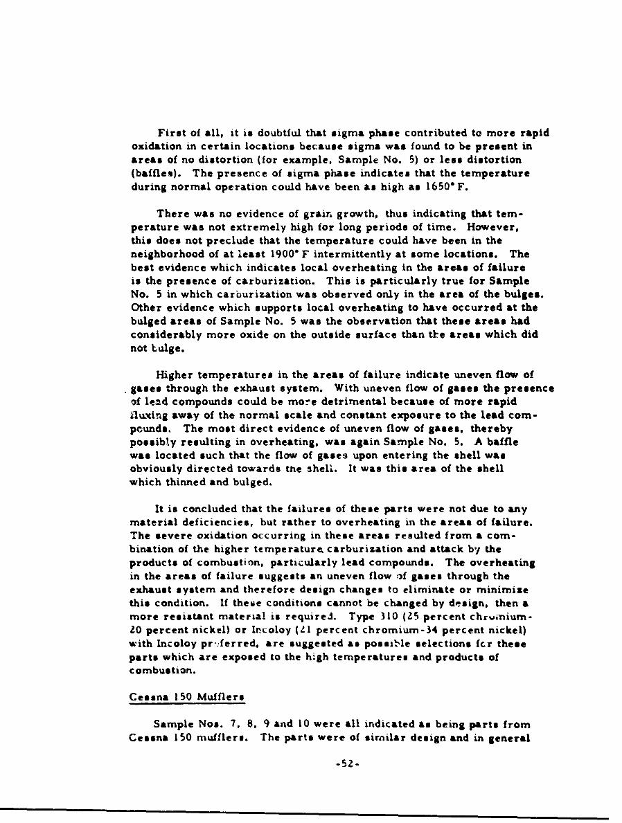
First of all, it is doubtful that sigma phase contributed to more rapidoxidation in certain locations because sigma was found to be present inareas of no distortion (for example, Sample No. 5) or less distortion(baffles). The presence of sigma phase indicates that the temperatureduring normal operation could have been as high as 1650" F.
There was no evidence of grain growth, thus indicating that tem-perature was not extremely high for long periods of time. However,this does not preclude that the temperature could have been in theneighborhood of at least 1900" F intermittently at some locations. Thebest evidence which indicates local overheating in the areas of failureis the presence of carburization. This is particularly true for SampleNo. 5 in which carburization was observed only in the area of the bulges.Other evidence which supports local overheating to have occurred at thebulged areas of Sample No. 5 was the observation that these areas hadconsiderably more oxide on the outside surface than tke areas which didnot bulge.
Higher temperatures in the areas of failure indicate uneven flow ofgases through the exhaust system. With uneven flow of gases the presenceof lead compounds could be more detrimental because of more rapidilu~xing away of the normal scale and constant exposure to the lead com-pounds. The most direct evidence of uneven flow of gases, therebypossibly resulting in overheating, was again Sample No. 5. A bafflewas located such that the flow of gases upon entering the shell wasobviously directed towards the shell. It was this area of the shellwhich thinned and bulged.
It is concluded that the failures of these parts were not due to anymaterial deficiencies, but rather to overheating in the areas of failure.The severe oxidation occurring in these areas resulted from a com-bination of the higher temperature. carburization and attack by theproducts of combustion, particularly lead compounds. The overheatingin the areas of failure suggests an uneven flow -f gases through theexhaust system and therefore design changes to eliminate or minimizethis condition. If theme conditions cannot be changed by design, then amore resistant material is requirei. Type 310 (25 percent chrvinium-Z0 percent nickel) or Incoloy (ZI percent chromium-34 percent nickel)with Incoloy pr:ferred. are suggested as possible selections fcr theseparts which are exposed to the high temperatures and products ofcombustion.
Cessna 150 Mufflers
Sample Nos. 7, 8. 9 and 10 were all indicated as being parts fromCessna 150 mufflers. The parts were of similar design and in general
-52-
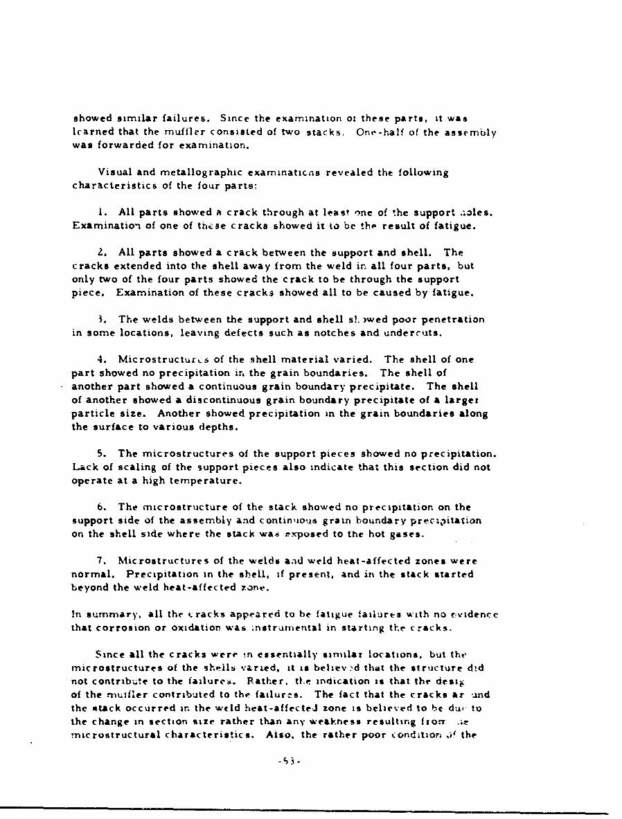
showed similar failures. Since the examination oi these parts. it waslearned that the muffler consisted of two stacks. One-half of the assemblywas forwarded for examination.
Visual and metallographic examinaticns revealed the followingcharacteristics of the four parts:
1. All parts showed a crack through at least 7ne of the support .- le$.Examination of one of these cracks showed it to be the, result of fatigue.
2. All parts showed a crack between the support and shell. Thecracks extended into the shell away from the weld in all four parts, butonly two of the four parts showed the crack to be through the supportpiece. Examination of these cracks showed all to be caused by fatigue.
3. The welds between the support and shell s!. )wed poor penetrationin some locations, leaving defects such as notches and undercuts.
4. Microstructurcs of the shell material varied. The shell of onepart showed no precipitation iri the grain boundaries. The shell ofanother part showed a continuous grain boundary precipitate. The shellof another showed a discontinuous grain boundary precipitate of a largerparticle size. Another showed precipitation in the grain boundaries alongthe surface to various depths.
5. The microstructures of the support pieces showed no precipitation.Lack of scaling of the support pieces also indicate that this section did notoperate at a high temperature.
6. The microstructure of the stack showed no precipitation on thesupport side of the assembly and contin'ao.io grain boundary precipitationon the shell side where the stack wa6 -x-posed to the hot gases.
7. Microstructures of the welds and weld heat-affected zones werenormal. Precipitation in the sbell, if present, and in the stack startedbeyond the weld heat-affected zone.
In summary, all the tracks appeared to be fatigue failures with no .videncethat corrosion or oxidation was ;nstrumental in starting the cracks.
Since all the cracks were in essentially similar locations, but the,microstructures of the sh.ils varied, it is believ d that the structure d-dnot contribute to the failure*. Rather. tO.e indication is that thr destz:of the muifler contributed to the failures. The fact that the cracks Azr -idthe stack occurred in the weld heat-affected zone is believed to be du4 tothe change in section size rather than any weakness resulting lionr .ie
microstructural characteristics. Also. the rather poor condition i' the
-",3-
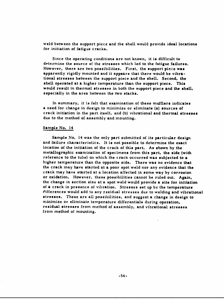
weld between the support piece and the shell would provide ideal locationsfor initiation of fatigue cracks.
Since the operating conditions are not known, it is difficult todetermine the source of the stresses which led to the fatigue failures.However, there are two possibilities. First, the support pit-e wasapparently rigidly mounted and it appears that there would be vibra-tional stresses between the support piece and the shell. Second, theshell operated at a higher temperature than the support piece. Thiswould result in thermal stresses in both the support piece and the shell,especially in the area between the two stacks.
In summary, it is felt that examination of these mufflers indicatesa need for change in design to minimize or eliminate (a) sources ofcrack initiation in the part itself, and (b) vibrational and thermal stressesdue to the method of assembly and mounting.
Sample No. 14
Sample No. 14 was the only part submitted of its particular designand failure characteristics. It is not possible to determine the exactlocation of the initiation of the crack of this part. As shown by themetallographic examination of specimens from this part, the side (withreference to the tube) on which the crack occurred was subjected to ahigher temperature than the opposite side. There was no evidence thatthe crack may have started at a poor spot weld nor any evidence that thecrack may have started at a location affected in some way by corrosionor oxidation. However, these possibilities cannot be ruled out. Again,the change in section size at a spot weld would provide a site for initiationof a crack in presence of vibration. Stresses set up by the temperaturec4ifferences would add to any residual stresses due to welding and vibrationalstresses. These are all possibilities, and suggest a change in design tominimize or eliminate temperature differentials during operation,residual stresses from method of assembly, and vibrational stressesfrom method of mounting.
-54-
CONCLUSIONS
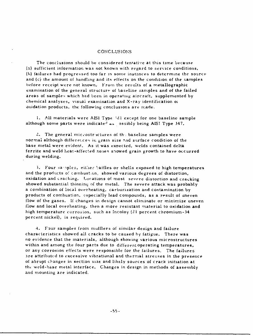
The conclusions should be considered tentative at this time because(a) sufficient information was not known with regard to service conditions,(b) failures had progressed too far in some instances to determine the sourceand (c) the amount of handling and its effects on the condition of the samplesbefore receipt were not known. From the results of a metallographicexamination of the general structure of baseline samples and of the failedareas of samples which had been in operating aircraft, supplemented bychemical analyses, visuai examination and X-ray identification oioxidation products, the following conclusions are nmade.
1. Ali materials were AISI Typf. ',Zl except for one baseline samplealthough some parts were indicatea .. ossibly being AIS! Type 347.
2. The general mic.ostr-ic Lures of th. baseline samples werenormal although differe:.ces in, grain size and surface condition of thebase metal were evident. As it was expected, welds contained deltaferrite and weld heat-affected -.oiaes siowed grain growth to have occurredduring welding.
3. Four sa'nples, eit'ier 1-atfles or shells exposed tc high temperaturesand the products or coinbust crn, showed various degrees of distortion,oxidation and cracking. Locations of most severe distortion and crackingshowed substantial thinning of the metal. The severe attack was probablya combination of local overheating, carburization and contamination byproducts of combustion, e-specially lead compounds, as a result of unevenflow of the gases. If changes in design cannot eliminate or minimize unevenflow and local overheating, then a more resistant material to oxidation andhigh temperature corrosion, such as Incoloy (21 percent chromium-34percent nickel), is required.
4. Four samples from mufflers of similar design and failurecharacteristics showed all cracks to be caused by fatigue. There wasno evidence that the materials, although showing various microstructureswithin and among the four parts due to different operating temperatures,or any corrosion effects were responsible for the failures. The failuresare attributed to excessive vibrational and thermal stresses in the presenceof abrupt ch-anges in section size and likely sources of crack initiation atthe weld-base metal interface. Changes in design in methods of assemblyand mounting are indicated.
-55-
5. A tailpipe support failed by Jatigue. Examination showed that oneside (with reference to the pipe) operated at a higher temperature than theother. Again, the failure appears to have been due to excessive vibrationaland thermal stresses rather than a defiLiency of the material or corrosioneffects.
-56-
APPENDIX I
GENERAL REFERENCES ON STAINLESS STEELS
1. Corrosion Resistance of Metals and Alloys, edited by F. L. LaQueand H. R. Copson, Second Edition, Reinhold Publishing Corporation,New York (1963), pages 375-445.
2. Corrosion and Corrosion Control, by H. H. Uhlig, John Wiley andSons, Inc., New York (1963), pages 258-283.
3. Stainless Steels, by C. A. Zappfe, American Society for Metals,Cleveland (1949).
4. Corrosion of Metals, American Society for Metals, Cleveland (1946),pages 51-99.
5. Corrosion, edited by L. L. Shreir, John Wiley and Sons, Inc.,New York (1963), pages 3.33-3.43, 3. 50-3.73, 7.56-7.79.
6. Corrosion Resistance of the Austenitic Chromium-Nickel StainlessSteels in High Temperature Environments, The International NickelCompany, Inc., New York, 1963.
7. H. L. Eiselstein and E. N. Skinner, "The Zffect of Composition onthe Scaling of Iron-Chromium-Nickel Alloys Subjected to Cyclic Tem-perature Conditions," ASTM Special Technical Publication No. 165,1954.
8. J. J. Moran, E. N. Skinner and F. L. LaQue, "Materials for Anti-Smog Devices," Metals Engineering Quarterly, Vol. 2, May 1962,pages 35-41.
9. Metals Handbook, Eighth Edition, Vol. 1, American Society forMetals, Metals Park, 1q61, pages 552-553, 564-566, 581-596, 598,614, 630.
APPENDIX I
Page 1 of 1