f2f meeting on 29 th and 30 th sept 2014. background in a joint meeting of “m2m policy &...
TRANSCRIPT

M2M Gateway and Architecture Working Group
F2F Meeting on 29th and 30th Sept 2014
BackgroundIn a Joint meeting of “M2M Policy & Regulatory
Committee”, “M2M Consultative Committee” on 13th August 2013, it was decided that a questionnaire will be released by DOT to gather inputs from various industry segments towards M2M.
DOT released a questionnaire in September 2013 for which it received around 50 responses from various stake holders from the industry.
Subsequently TEC was entrusted with the task of framing specifications for M2M in India. Five Working Groups were formed namely Automotive, Power, Health, Surveillance and M2M gateway (later rechristened as Gateway and Architecture WG)

Term of Reference (Framework of Reference) for Working groups of M2M domain (Excerpts)
Machine to machine (M2M) communication is considered to be a key enabler of applications and services across a broad range of vertical markets. A common M2M service layer, agreed at the global level involving stakeholders from the M2M and vertical market communities, would provide a cost-efficient platform, which can be easily deployed in hardware and software, in a multi-vendor environment, and across sectors.
Working groups will, inter-alia, identify a minimum set of common requirements of vertical markets, focusing on vertical related market and application programming interfaces (APIs) and protocols supporting applications and services, and draft technical reports in these areas.
The Journey So FarVarious architecture options available for M2M communication
were discussed.C-DOT presented a generic Architecture for M2M and suggested
that every layer shall be independent so that there can be business case for entrepreneurs for every element of the architecture.
Ericsson gave an overview of the OneM2M architecture and suggested that since a lot of work has already been done by that forum, it would be prudent to study that and try to see if that fits all the scenarios relevant for India. If need be it can be slightly tweaked to suit us.
It was also suggested that the architecture group should look at all the use cases currently prevailing and then try to map them in the architecture. It was decided thereafter to include the chair and rapporteur of all other Working Groups into the architecture working group.
The Journey So Far contd… It was suggested that the viewpoint of device
manufacturers must be taken into account and in this direction HPL gave an overview of the metering solution used by them. It was thereafter suggested that if the meter manufacturers standardize on any interface, then various pluggable communication adapters can be designed and manufactured by various manufacturers which can be used in diverse ergonomics
The use of IPv6 in the M2M architecture was deliberated. The group unanimously agreed on using IPv6 exclusively at the Device Gateway level and beyond but expressed concern for its exclusive use in the PAN/HAN. It was though agreed that in future there would be a need to uniquely address each device and for that purpose IPv6 is the most suitable choice. It was therefore agreed that all currently prevailing local area protocols used in the M2M applications would be accommodated in the architecture.
The use case of Continua Alliance in the health industry was discussed.
Use cases on Automobiles were presented by TTSL which was discussed in detail.[C-DOT and ETSI opined that though the public safety part of the Automobile use case discussed by TTSL was of extreme importance but at the same time it cannot be classified in the M2M category of application considering the definition of M2M. It was debated and was considered as a subject for further study and deliberations.]
Use case on 6LoWPAN was discussed in detail.Use cases on AMI were discussed in detail.
The Journey So Far contd…

Pipe (vertical):1 Application, 1 NW,
1 (or few) type of Device
Horizontal (based on common Layer)Applications share common infrastructure, environments, network elements & data
Local N/W
BusinessApplication #1
BusinessApplication
Device
Transport Network 1
Transport Network (mobile, fixed, Powerline ..)
Transport Network 2
Gateway
Local N/W
Device Device Device Device
Common Service Capabilities
Gateway
IP
Business platform
BusinessApplication #2
BusinessApplication #n

Vertical vs HorizontalWhile many applications were in place for
many industry segments following a ‘Vertical Architecture’, it was considered necessary to adopt a open standards based ‘Horizontal Architecture’
Horizontal ArchitecturePROS CONS
InteroperabilityStandardisation is always a tedious process in the
beginning and the time to market is long
Boost to Entrepreneurship
Optimal use of Resources
Choice for customers

It was considered appropriate by the Gateway and Architecture Working Group
that since a lot of progress towards framing the architecture has been made by
OneM2M, the same shall be adopted as the base architecture and India specific tailoring be done on that (if needed by any specific use case for any vertical)
AE AE
Mca Mca Mca
Mcc
Mcn Mcn
CSE CSE
NSE NSE
Field Domain Infrastructure Domain
To Infrastructure Domain of other Service Provider
Mcc’
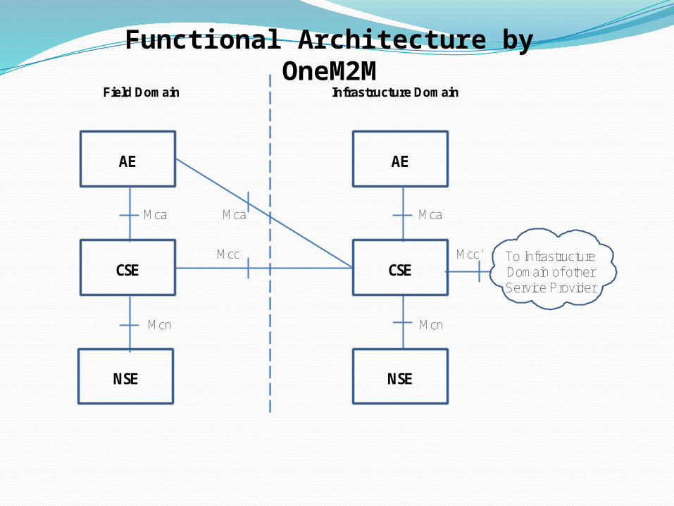
Functional Architecture by OneM2M
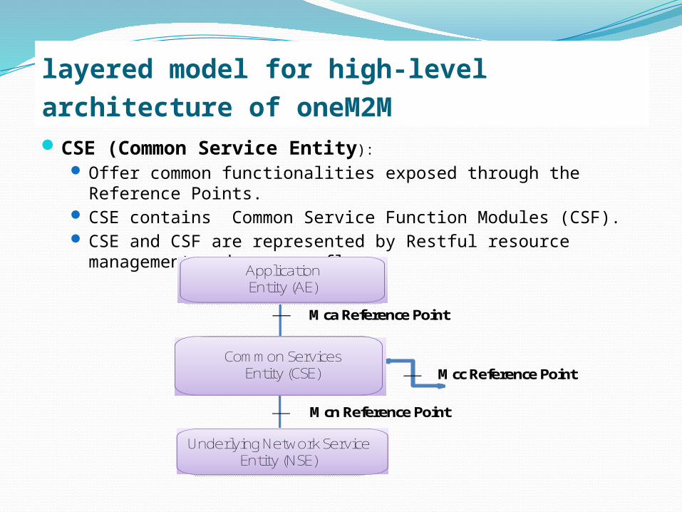
layered model for high-level architecture of oneM2M CSE (Common Service Entity):
Offer common functionalities exposed through the Reference Points.
CSE contains Common Service Function Modules (CSF). CSE and CSF are represented by Restful resource
management and message flows.
Mca Reference Point
Mcc Reference Point
Mcn Reference Point
Application Entity (AE)
Common Services Entity (CSE)
Underlying Network Service Entity (NSE)
OneM2M Architecture FunctionsThe oneM2M functional architecture in figure comprises of the following functions:Application Entity (AE): Application Entity
represents an instantiation of Application logic for end-to-end M2M solutions. Each Application Entity is identified with a unique Application Entity Identifier.
Examples of the Application Entities can be an instance of a fleet tracking application, a remote blood sugar monitoring application, a power metering application, or a controlling application.
Common Services Entity (CSE): A Common Services Entity represents an instantiation of a set of "common service functions" of the M2M environments. Such service functions are exposed to other entities through reference points Mca and Mcc. Reference point Mcn is used for accessing Underlying Network Service Entities. Each Common Service Entity is identified with a unique CSE-ID.
Communication flows between a Common Services Entity (CSE) and the Network Services Entity (NSE) cross the Mcn reference point. These flows enable a CSE to use the supported services (other than transport and connectivity services) provided by the NSE.
OneM2M Architecture Functions
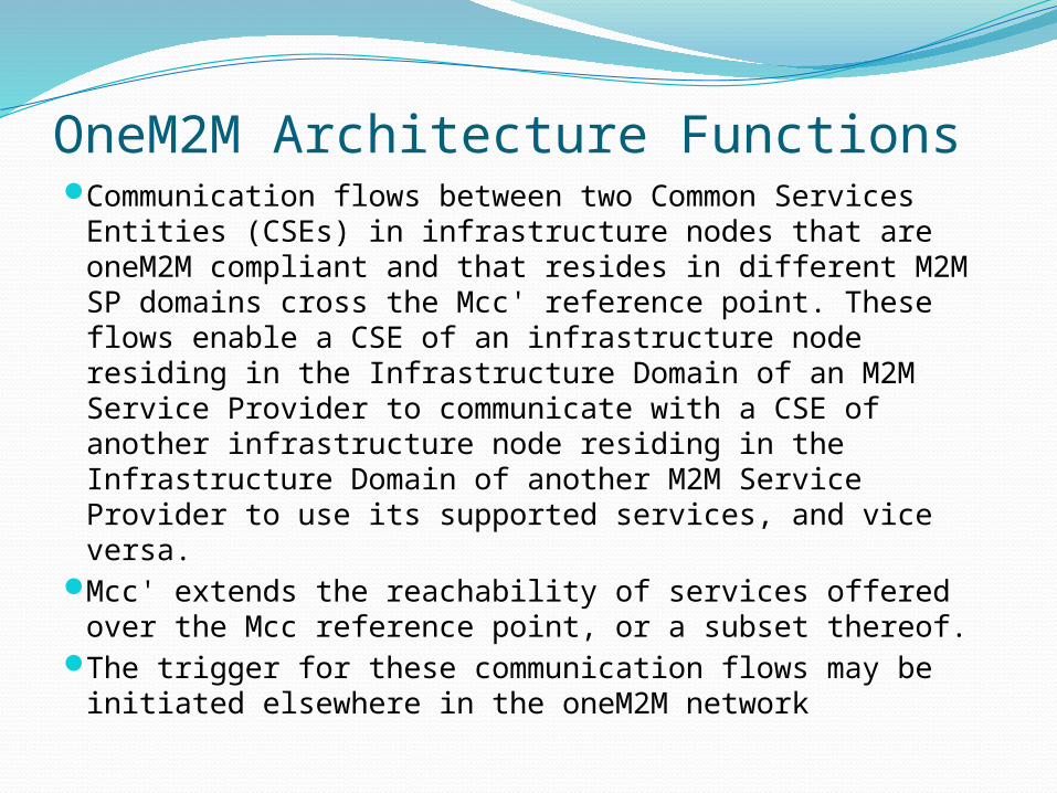
Communication flows between two Common Services Entities (CSEs) in infrastructure nodes that are oneM2M compliant and that resides in different M2M SP domains cross the Mcc' reference point. These flows enable a CSE of an infrastructure node residing in the Infrastructure Domain of an M2M Service Provider to communicate with a CSE of another infrastructure node residing in the Infrastructure Domain of another M2M Service Provider to use its supported services, and vice versa.
Mcc' extends the reachability of services offered over the Mcc reference point, or a subset thereof.
The trigger for these communication flows may be initiated elsewhere in the oneM2M network
OneM2M Architecture Functions

Communication flows which transfer CDRs generated by the IN to an external charging server cross the Mch reference point. The Mch reference point may be mapped to reference points of other specifications. E.g. for a 3GPP Underlying Network, the Mch reference point maps to the Rf reference point enabling a 3GPP charging server to be used for oneM2M CDRs.
Examples of service functions offered by CSE include: Data Management, Device Management, M2M Subscription Management, and Location Services. Such "sub-functions" offered by a CSE may be logically and informatively conceptualized as Common Services Functions (CSFs).
OneM2M Architecture Functions

Network Services Entity (NSE): An Underlying Network Services Entity provides services to the CSEs. Examples of such services include device management, location services and device triggering.
NOTE: Underlying Networks provide data transport services between entities in the oneM2M System. Such data transport services are not included in the NSE.
OneM2M Architecture Functions
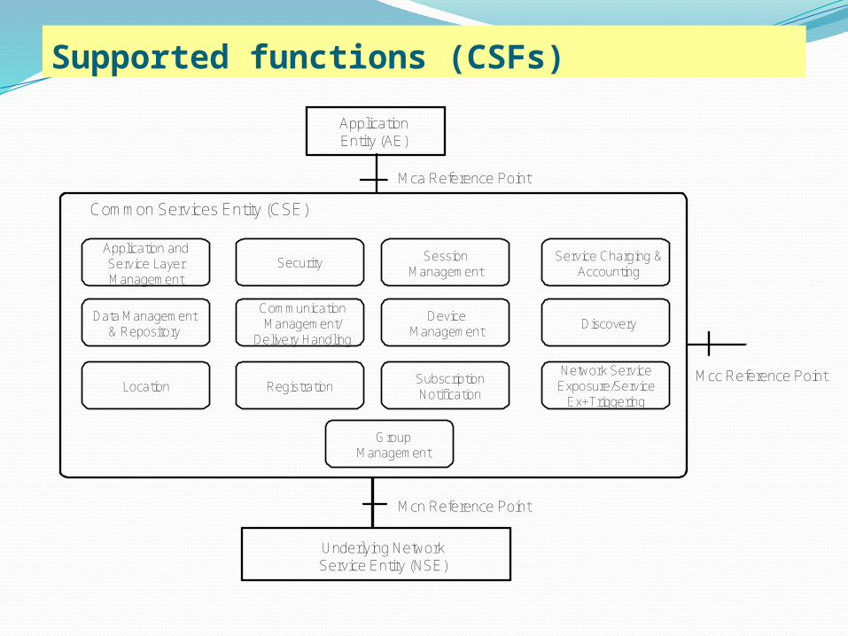
Supported functions (CSFs)
Mca Reference Point
Mcn Reference Point
Application Entity (AE)
Underlying Network Service Entity (NSE)
Common Services Entity (CSE)
Mcc Reference Point
Data Management & Repository
Location
Security
Communication Management/
Delivery Handling
Registration
Session Management
Device Management
Subscription Notification
Service Charging & Accounting
Discovery
Network Service Exposure/Service
Ex+Triggering
Group Management
Application and Service Layer Management

API Interface Consideration in oneM2M: RESTRESTREST stands for Representational State Transfer. It is a
style of API interface. When the API of a system qualifies REST's features, we say the system is RESTful.
REST was first described by R.T. Fielding in his Doctoral Dissertation [i.9]. The basic notion of REST is resource. Any information in the oneM2M system that can be named and addressed can be a resource: a document or image, a temporal service, a collection of other resources, a non-virtual object, a fragment of data, and so on. REST can be summarised to several basic constraints.
Client to Server. Client is separated from the Server by interfaces. As long as the interface stays the same, Client and Server can evolve separately.

The interface between client and server is Stateless. The request on the interface contains all the information needed for the server to handle the request.
Cache. Cache is used to improve the scalability and performance.
Uniform Interface. The resources could be addressed by the same methods. There are four constraints about the Uniform Interface:
identification of resources; manipulation of resources through representations; self-descriptive messages; hypermedia as the engine of application state
(HATEOAS).
REST (contd..)

REST (contd..)Layered system. The system is divided by several layers.
Each layer provides functions to the upper layer by utilise the functions provided by the lower layer. Each layer can evolve separately.
RESTful guarantees that the client needs no prior knowledge of the server. Every client can access to the resources using uniform interfaces. The method to parse the resource is along with the resource. A REST Client can interact with the server entirely using hypermedia provided by the server, which is the concept of HATEOAS. Resources are connected with each other using links. The REST Client can navigate from resources to resources to obtain the information desired. The HATEOAS constraint serves to decouple client and server in a way that allows the server to evolve functionality independently.
More and more architecture designers have adopted RESTful architecture in the M2M area; ETSI M2M , OMA DM2.0 , OMA LWM2M , IETF CoRE CoAP etc.

Finally: Key Recommendations by the G&AGUse of Open Standard based architecture
(preferably OneM2M (Tailored, if necessary)Use of IPv6 (if possible static, if not then
fused) to the extent possible in all the M2M devices which communicate to the network entity
Wherever possible, the AAA function shall be brought closest to the M2M Device and away from the AE
TEC Type approval and interface approval shall come into force for M2M devices and APIs
All verticals to fill the INDIAN M2M USE CASE capturing template

Thank You