f01d2000 installation guide.pdf
TRANSCRIPT

HUAWEI TECHNOLOGIES CO., LTD.
F01D2000
Quick Installation Guide
Issue: 03
Date: 2012-05-15

1
Contents
1 Precautions ………………………………………………………......................................2
2 Installation Tools ……………………………………………………….............................3
3 Cabinet Appearance and Cabinet Structure …………………………………………....4
4 Installing the Cabinet on the Concrete Pedestal ………………………...……………...5
5 Opening the Cabinet Door …………………………….............………………………....9
6 Routing Cables …………………..………………...………..................................…...…10
6.1 Connecting AC Power Cables and PGND Cable ............................................................................................11
6.2 Connecting External Subscriber Cables...........................................................................................................12
6.3 Connecting Optical Cables and Fibers (Configured With the UA5000)......................................................... 13
6.4 Connecting Optical Cables and Fibers (Configured With the MA5600T).......................................................14
7 Installing Batteries.............................................................................................................15
8 Checking the Cabinet Installation....................................................................................17
9 Powering On the Device.....................................................................................................18 9.1 Powering On the Device (Configured With the UA5000)...............................................................................18
9.2 Powering On the Device (Configured With the MA5600T)............................................................................19
10 Sealing the Cabinet...........................................................................................................20
11 FAQs for Installation........................................................................................................21
12 FAQs for Installation........................................................................................................22

2
Precautions
Bundling Cables
• The distance between cable ties or binding straps inside the cabinet must be within 250 mm. (For user cable, the distance
must be within 200 mm.)
• Use a diagonal pliers to cut off the extra part of the cable tie to the end, and ensure that the cable tie is neat without sharp
edges to prevent hand injury.
Affixing Labels / Fastening Tags
• After routing the cable, affix the label or fasten the tag to the cable, and 20 mm away from the connector.
• After the label for the signal cable is attached to the signal cable, the rectangular text area of the label must face
rightwards or downwards.
• After the identification plate for the power cable is attached to the power cable, the text area of the plate must face
rightwards or upwards. Ensure that the side attached with the label faces outwards.
• This document aims to provide simple and distinctive guidelines for hardware installation.
• This document does not describe operations for the pre-delivery installation of the internal cables and so on. Instead, this document
describers only the operations for on-site installation.
Electrostatic Discharge
Before touching the device, or holding the boards and IC chips, wear the ESD gloves or the ESD wrist strap to prevent the
electrostatic discharge of the human body from damaging the sensitive components. Ensure that the other end of the ESD wrist
strap is properly grounded.
Copyright © Huawei Technologies Co., Ltd. 2012 . All rights reserved.
Using the desiccant
• After removing the packing case of the cabinet on the site, take out the desiccant packages from the corresponding paper
bag (Note: Do not tear the own packages of the desiccant). Then, put the desiccant packages at proper places of the cabinet.
• After powering on the cabinet, the desiccant packages must be removed and disposed of as an industrial waste.

3
Installation Tools
Measuring tape Flathead screwdriver Philips screwdriver Socket wrench
Percussion drill
Hammer
Torque wrench Crowbar
Multimeter Impact tool Wire crimping tool
Wire stripper Network cable pliers
Brush ESD wrist strap
Diagonal pliers

4
Cabinet Appearance and Cabinet Structure
ODF
Power system
Service shelf
Fiber
Cable distribution compartment
Service shelf
Battery compartment
Outer installation hole 6-Φ18 Copper cable hole 4-Φ99
Inner installation hole
(optional) 4-Φ18
800
1850
MDF
Power cable hole Φ33
Dimensions of Installation Interfaces
Cabinet Appearance
Unit: mm
Unit: mm
Copper cable hole Optical cable hole 2-Φ33
1750
PGND cable hole Φ33
Copper cable hole 4-Φ99

5
Installing the Cabinet on the Concrete Pedestal
a
Plan the Space for the Concrete Pedestal
b
Construct the Concrete Pedestal
Unit: mm
Front
Construct the concrete pedestal. Decide the specific method for
constructing the concrete pedestal based on the local standards.
Ensure the constructed concrete pedestal is horizontal.
The horizontal deviation must be within 4 mm.
Face the cabinet front door
towards south or north if
possible. This ensures that the
cabinet receives the minimum
solar radiation.
NOTE
A A
B
B
Outer installation hole (80 mm
depth) 6-Φ16
Unit: mm
Inner installation hole
(optional, 80mm depth)
4-Φ16
Cable hole

Bearing capacity of the steel cable > 1950 kg
125
100
100
125
Cabinet position
Unit: mm
6
M12x60 bolt
Spring washer
Flat washer
Expansion tube
Guide trough
Cone bolt 52-60 Φ16
Unit: mm
c
Drill Holes and Install Expansion Bolts
d
Carry the Cabinet
Protect the parts where the cabinet contacts the steel rope to avoid
any damages to the cabinet surface.
• When drilling holes, you can use a punch tool to chisel a pit to help position the bit.
• Hold the drill firmly and keep the drill bit vertical to the concrete pedestal. Ensure that the drill does not shake when you
are drilling holes, as this may result in uneven holes.
90º

800~1000
800~1000
800~1000
≥490
Unit: mm
≥410
≥410
7
Cover of the installation foot Sealing gel
e
Fasten the Cabinet (Outer installation hole)
CAUTION
• Construct the protection fence after installing
the cabinet.
• Plan the coverage of the protection fence
based on the ground plan to ensure that all
doors of the cabinet can be opened without
difficulties.
Packaging bag (cover of the
installation foot, sealant)
CAUTION
• When fastening the cabinet, after
you cover the cover of the
installation foot, you need to seal
the installation foot with the
transparent or white silica gel.
• After installing the cabinet on a
concrete pedestal, use silicon gel
to seal the cabinet bottom
properly.

8
After fastening the cabinet,
use waterproof glue around
the expansion bolt to seal the
installation hole.
CAUTION
e
Fasten the Cabinet (Optional: Inner installation hole)
800~1000
800~1000
800~1000
≥490
Unit: mm
≥410
≥410
CAUTION
• Construct the protection fence after installing
the cabinet.
• Plan the coverage of the protection fence
based on the ground plan to ensure that all
doors of the cabinet can be opened without
difficulties.
Inner installation hole
(optional) 4-Φ18
For details about how to open the cabinet door, see
Opening the Cabinet Door.
NOTE

9
The equipment compartment of the cabinet uses
the HW-2802A lock, and the cable distribution
compartment uses the HW-2802B lock. The keys
of these two types of locks are different, as shown
by a and b in the figure.
NOTE
Opening the Cabinet Door

10
Routing Cables
• Before routing various cable into the cabinet, you need to open the cover of the handhole at the bottom of the MDF
compartment.
• After routing the cables, you need to set back the cover.
CAUTION
Open the cover of the handhole
Cover of the handhole
11
Routing Cables
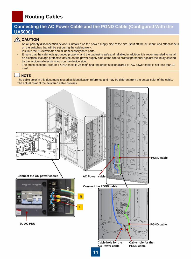
Connecting the AC Power Cable and the PGND Cable (Configured With the
UA5000 )
• An all-polarity disconnection device is installed on the power supply side of the site. Shut off the AC input, and attach labels
on the switches that will be set during the cabling work.
• Insulate the AC terminals and all unnecessary bare parts.
• Ensure that the cabinet is grounded properly, and the cabinet is safe and reliable; in addition, it is recommended to install
an electrical leakage protective device on the power supply side of the site to protect personnel against the injury caused
by the accidental electric shock on the device side.
• The cross-sectional area of PGND cable is 25 mm2 and the cross-sectional area of AC power cable is not less than 10
mm2 .
CAUTION
Connect the PGND cable
Cable hole for the
PGND cable
Cable hole for the
AC Power cable
PGND cable
Connect the AC power cables
3U AC PDU
L
N
PGND cable
AC Power cable
The cable color in this document is used as identification reference and may be different from the actual color of the cable.
The actual color of the delivered cable prevails.
12
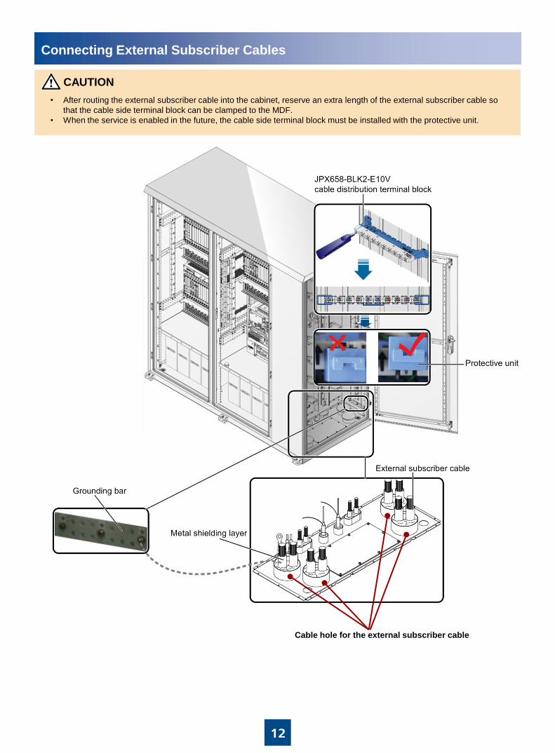
Connecting External Subscriber Cables
• After routing the external subscriber cable into the cabinet, reserve an extra length of the external subscriber cable so
that the cable side terminal block can be clamped to the MDF.
• When the service is enabled in the future, the cable side terminal block must be installed with the protective unit.
CAUTION
Cable hole for the external subscriber cable

13
Connecting Optical Cables and Fibers (Configured With the UA5000)
• You must use corrugated tube to protect core wires of optical cables in the cabinet, and use the binding strap to bind
optical fibers; do not drag or bind the optical fiber too tightly.
• The bending radius of the optical cable core or optical fiber must be 20 times larger than the diameter of the optical
cable core or optical fiber. Generally, the bending radius is larger than or equal to 40 mm.
• Install the optical module properly, and make sure that the rings of the optical module are locked.
Do not look into the optical port without eye protection.
Cable hole for the optical cable
To optical ports on the control board
14
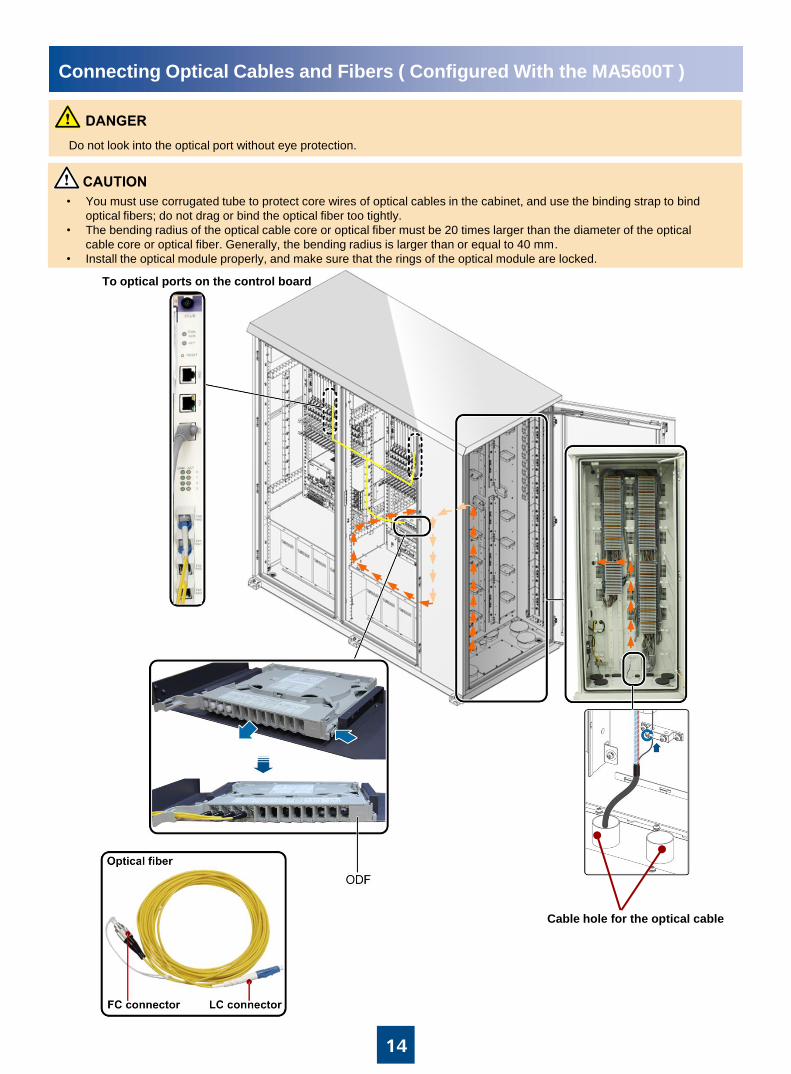
Connecting Optical Cables and Fibers ( Configured With the MA5600T )
• You must use corrugated tube to protect core wires of optical cables in the cabinet, and use the binding strap to bind
optical fibers; do not drag or bind the optical fiber too tightly.
• The bending radius of the optical cable core or optical fiber must be 20 times larger than the diameter of the optical
cable core or optical fiber. Generally, the bending radius is larger than or equal to 40 mm.
• Install the optical module properly, and make sure that the rings of the optical module are locked.
Do not look into the optical port without eye protection.
Cable hole for the optical cable
To optical ports on the control board
15
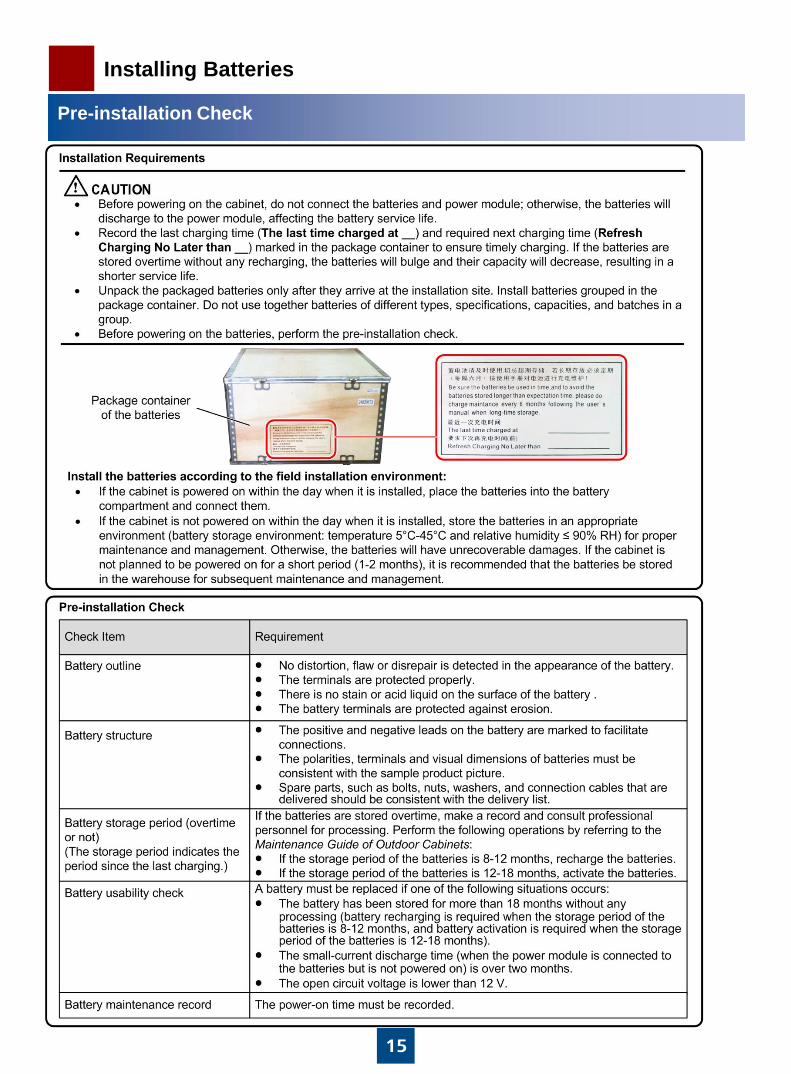
Installing Batteries
Pre-installation Check

16
Installing Batteries
Follow exactly the installation procedure to install the batteries. Wrap the metal installation tools, such as wrench, with
insulation tape for insulation. Any short circuit may hurt personnel and damage the equipment.
DANGER
• Before laying out the battery power cable, ensure that the battery switch is in the OFF state.
• Ensure that the polarity position of each battery is correct. The connection between two batteries, or the connection
between batteries and the power system/battery interface of the device must be firm and correct.
• Keep a space of at least 10 mm between batteries for heat dissipation.
• After the batteries are installed, the battery parameters must be configured during software commissioning. Otherwise,
the battery life may be shortened.
CAUTION
Installing the 150 Ah Batteries
Battery interconnecting cable
The battery switch is OFF
Fastening battery cables with
M6 screws (torque: 5 N·M).
CAUTION

17
Checking the Cabinet Installation
NO.
Item
Method
1 The structural parts of the cabinet are installed correctly and properly.
The cabinet door is not distorted during the transportation. The board can
be inserted or removed easily. Customized parts are installed according
to the requirements.
Check and use.
2 The painted surface of the cabinet is properly protected. Check the cabinet. Paint the
cabinet again if necessary to
avoid rust.
3 The cabinet is fastened reliably and meets the quakeproof requirement
specified in the engineering document.
Check whether the Six bolts
are fastened properly.
4 The cabinet installation site meets the requirement specified in the
engineering document.
Check the installation site.
5 All cable holes, including those for the power cable, ground cable, optical
cable, and external subscriber cable, are properly sealed.
Check.
6 The external positive and negative terminals of the battery are correctly
and reliably connected to the EPS75-4815AF power system.
Test with the multimeter.
7 The protective cap on the wiring terminal of the battery is intact. Check.
8 All cables are free of damage, fracture, or joint in the middle of the cable. Check.
9 The power cable and the ground cable are made of an entire section of
copper wire. The cables are free of joint in the middle or damage on the
jacket.
Check.
10 The radiuses of the power cable and the ground cable meet the
requirement specified in the engineering document and the power
distribution requirement of the device.
Check (check the actually
delivered cables if the cables
are from Huawei).
11 The optical fiber connector and the board optical port to be used are
protected with protective caps. If necessary, clean the connector and the
port in compliance with Huawei regulations.
Check.
12 The cable outside the cabinet is buried underground, if possible. If the
cable is routed through the overhead cabling, adopt the lightning proof
measures.
Check.
13 The cabinet is grounded properly and the ground resistance is smaller
than 10 ohms.
Measure with the earth
resistance meter.
14 An electrical leakage protective device is installed on the power supply
side of the site. If such a device does not exist, it is recommended to
install this device.
Check.
15 An all-polarity disconnection device is installed on the power supply side
of the site. If such a device does not exist, it is recommended to install
this device.
Check.
16 The inner cabinet is clean and neat, and free of redundant sundries.
Ensure that the air intake vent and air exhaust vent of the device are not
blocked by any object.
Check.

18
Powering On the Device
• The cabinet must be powered on in seven days after installation.
• To ensure the safety, before powering on the device, check whether condensation exists in the cabinet. Power on the
device only after you ensure that no condensation exists. For the detailed method of removing condensation, see the
corresponding label on the cabinet front door.
During the power-on, before and after turning on each circuit breaker for the first time, you must use a multimeter to
check the input and output voltages and ensure that the voltages are normal (AC ranges: 200 V AC to 240 V AC; DC
range: –42 V DC to –58 V DC).
• After installing the cabinet and powering on the device, ensure that the battery switch is in the ON state. If the device
needs to be powered off, you must first turn off the battery switch and then turn off the AC switch.
CAUTION
When the fan tray works in the
normal state, the green LED is
on for 1s and off for 1s
repeatedly. Green : on for 1s
and off for 1s
repeatedly
Green : on
Green : off
RCD for maintenance
sockets RCD2
(optional)
Powering On the Device ( Configured With the UA5000 )
Switches for DC PDU
Main switch
EPS75-4815AF-VB power system
Green : on for 1s
and off for 1s
repeatedly
Monitoring unit Rectifier unit
Green :
on

19
Powering On the Device
• The cabinet must be powered on in seven days after installation.
• To ensure the safety, before powering on the device, check whether condensation exists in the cabinet. Power on the
device only after you ensure that no condensation exists. For the detailed method of removing condensation, see the
corresponding label on the cabinet front door.
During the power-on, before and after turning on each circuit breaker for the first time, you must use a multimeter to
check the input and output voltages and ensure that the voltages are normal (AC ranges: 200 V AC to 240 V AC; DC
range: –42 V DC to –58 V DC).
• After installing the cabinet and powering on the device, ensure that the battery switch is in the ON state. If the device
needs to be powered off, you must first turn off the battery switch and then turn off the AC switch.
CAUTION
Green : on for 1s
and off for 1s
repeatedly
Monitoring unit Rectifier unit
Green :
on
RCD for maintenance
sockets RCD2
(optional)
Powering On the Device ( Configured With the MA5600T)
Switches for DC PDU
Main switch
EPS75-4815AF-VB power system
When the fan tray works in the
normal state, the green LED is
on for 1s and off for 1s
repeatedly.

Sealing material
20
Sealing the Cabinet
b
Close the Cabinet Door
a
Seal the Cable hole
• Cover the sealing material ( such as silica gel and sealant, bundled on the left grounding bar at the bottom of the cable
distribution compartment) onto the cable hole at the bottom of the cabinet to seal the cable hole gap and the gaps among
cables.
• After the engineering installation of the cabinet is completed and before the device is powered on, to avoid the condensation
in the cabinet, you need to remove the packaging bag from the desiccant (four packages) that is attached to the cabinet.
Three packages are at the bottom of the device compartment and the other one package at the bottom of the cable
distribution compartment. Remove the desiccant packages and VCI-powder packages only when the device is powered on
next time.
• After installing the cabinet on a concrete pedestal, use silicon gel to seal the cabinet bottom properly.
CAUTION
Packaging bag
(cover of the
installation foot,
sealant)
Desiccant

21
FAQs for Installation
22
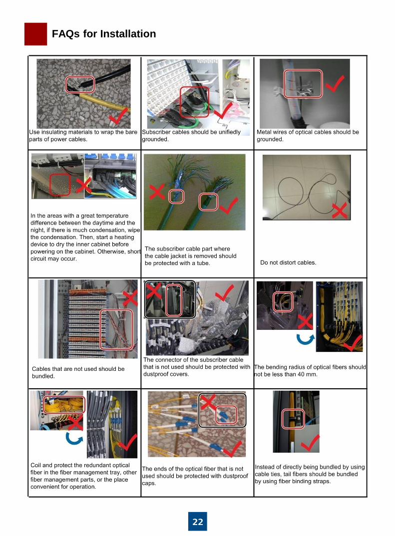
FAQs for Installation

HUAWEI TECHNOLOGIES CO., LTD. Huawei Industrial Base Bantian Longgang
Shenzhen 518129
People’s Republic of China
www.huawei.com