f. nanofiber reinforced polymer-polymer composites 14...
TRANSCRIPT

1
F. Nanofiber reinforced polymer-polymer composites
14. Electrospun composite nanofibers and polymer composites
Kolos Molnár and László Mihály Vas, Budapest University of Technology and Economics,
Hungary
Mr. Kolos Molnár – Mechanical Engineer, PhD student, Department of Polymer Engineering, Faculty of
Mechanical Engineering, Budapest University of Technology and Economics.
Postal address: Műegyetem rkp 3., H-1111, Budapest, Hungary
Tel.: +36-1/463-1525
Fax.: +36-1/463-1527
e-mail: [email protected]
Prof. Dr. László Mihály Vas – Scientific advisor, Department of Polymer Engineering, Faculty of Mechanical
Engineering, Budapest University of Technology and Economics.
Postal address: Műegyetem rkp 3., H-1111, Budapest, Hungary
Tel.: +36-1/463-1529
Fax.: +36-1/463-1527
e-mail: [email protected]

2
Keywords
Beaded fibers
Branching jet
Bubble electrospinning
Buckling jet
Carbon nanofibers
Carbonization
Carbonized nanofibers
Charge injection electrospinning
CNT reinforced nanofibers
Coating with nanofibers
Coaxial electrospinning
Composite nanofibers
Conjugate electrospinning
Core-shell nanofibers
Disc collector
Drum collector
Electrically charged rings
Electrospinning
Electrospraying
Electrospun interlaminar layers
Electrospun yarn
Exocomposite fibers
Functionalization
Interlaminar reinforcing
Interlaminar toughening
Nanofiber bundle
Nanofiber composites
Nanofibers
Nanofibrous structures
Nanofiber web
Nanofiber yarn
Nanoparticle embedded nanofibers
Polyacrylonitrile
Self bundling
Spinneret
Spinneret electrode
Taylor cone
Wet spinning

3
14.1 Introduction
Nowadays the field of synthetic polymer-polymer composites (PPCs) is characterized by very
rapid progress. It is because new ideas forming the basis of new technologies often require new
materials to be developed. Thus new materials such as nanofibers and nanofiber reinforced
composites can lead to newer ideas and further applications and these further applications in turn
can lead to the development of more specialized materials. PPC industry requires advanced
matrices, advanced reinforcements, advanced additives and advanced technologies and also the
application fields are still widening.
This chapter tries to interpret electrospun materials and their applications from the materials
aspect although we try to reflect on future applications as well as on the need for functionalized
materials which led to the development of the existing ones.
The demand for special synthetic fibers for the composites industry has been continuously
growing. In this context special means that these fibers have some unique properties making
them applicable to build high strength, highly functional or smart materials and composites or
they can modify the mechanical properties of composites even by applying only a small amount
of them. In the last two decades the research on fibers basically branched into three different sub-
directions.
The first one is microfibers with unique mechanical properties [1]. It has always been a challenge
for scientists and for companies to develop stronger fibers, new fibers with higher modulus or
even to advance their former products in order to increase strength. If we have a look at this from
the application side, for example in case of automotive and aeronautical applications fuel can be
saved by decreasing weight. It can be made by exchanging existing composite parts in the design
construction for advanced composites which have more efficient reinforcement.
The second way is to create specially functionalized fibers [3]. There may be different reasons for
doing this such as better adhesion between fiber and matrix, conductive fibers against lightning
strikes or for microelectronics, self-healing composites, quality insurance, damage analysis,
sensing, etc. This field is quite interdisciplinary, because these innovations are advantageous not
only for the composite industry but also for many others. Just to mention a few: textile industry
and clothing (e.g. photo luminescent fibers), biomedical applications (e.g. drug delivery),

4
filtration (e.g. functionalized filters to remove toxic or hazardous materials from water), sensors
(e.g. more efficient and sensitive ones), etc.
The third direction which was the concept of diameter reduction has led to the group of
‘nano’fibers, although such fibers can also be built up in a bottom-up way [1]. This group is
somehow the combination of the two former groups because the aim in this case is both increased
strength and functionalization. The decrease of the fiber diameter generally leads to an increased
strength because of the so-called size-effect [2]. This phenomenon revived the development of
nanocomposites and nano-reinforcements where the typical size of reinforcement is in the
nanometer or submicron scale.
Nano-additives are able to further functionalize the materials or can even be used to produce
hybrid composites [5-6]. Even the fibers can be composites themselves where for example
microfibers or even nanofibers are reinforced with carbon nanotubes (CNTs) [7-8] or with
nanoclay [9-10], etc. In these cases nano-reinforcement is typically embedded into a fiber which
becomes a kind of matrix itself. These composite fibers can have excellent tensile properties [7]
or can be used for detecting damage in composite structures [11] or can be precursors of carbon
fibers [12].
Fiber diameters can be decreased to the submicron-scale in several ways in order to get nano-
reinforcement. Nanofibers can have unique properties which primarily originate from their small
diameter. They are very flexible and have a very high surface to mass ratio. Self-crystalline
polymer nanofibers can have different cristallinity compared with microfibers [13-14]. They can
have very high aspect ratios which is preferable to establish a good adhesion with the matrix.
These continuous fibers can mostly be used in hybrid composites in combination with
microfibers. In principle it is possible to reinforce composites with nanofibers alone but
nowadays our knowledge is very limited in this field.
Nanofibers include many types depending on their material and manufacturing processes, for
example: electrospun nanofibers, various titania (TiO2) nanofibers [15], special ceramic-based
nanofibers [16], supersonic laser drawn nanofibers [17-18], sea-island-type conjugated melt spun
nanofibers [19], technologies include formation of nanofibrils from polymer blends [20], jet
blowing [21] and there are CNTs [22] and other special forms of carbon nanofibers [23].
As one can see, there are several types of nanofiber preparation, but for now it seems that
electrospinning is the most popular and emerging technique in case of continuous nanofiber

5
production [24]. There are many reasons for this, such as easy processability of a wide variety of
polymers [25] and ceramics [26], feasibility [27], etc. Unlike many nano-structures which are
produced in a bottom-up way, electrospinning offers a top-down process resulting in cost-
effectiveness and easy processing. Scanning electron micrograph of a typical electrospun material
can be seen in Figure 1.
Figure 1 Scanning electron micrograph (SEM) of electrospun poly(vinylalcohol) (PVA) nanofibrous mat
This subsection introduces electrospun nanofibers and their typical behavior and moreover it tries
to give a short introduction why and how it can be a feasible way to reinforce or even toughen
PPCs with nanofibers. The general benefits of nanofibers can also be emphasized. Nanofibers are
usually form a cross-linked fiber net, which is not harmful to human and animal health, in the
sense that it does not cause silicosis nor is carcinogenic, etc. as other nanomaterials [28]. On the
other hand there are several feasible and cost-effective and simple ways to produce these
nanofibrous materials. These can have different formats, such as yarns [29-32], nonwovens, mats
with oriented structure [33], unidirectional fabrics [34], and 3D structures as well [35]. These
different formats can lead to different application fields or stated otherwise for a wide spectrum
of applications the appropriate format of these nanomaterials can be produced. These
nanomaterials have very high surface to weight ratio which is their main advantage for example

6
in drug delivery, filtration or in case of PPCs a better adhesion of fibers with the matrix material
can be achieved by simply increasing the contact surface [35-37].
This chapter deals with nanofibers processed by electrospinning method, their applications in the
composites industry, academic researches and with further developments in detail.
14.2 Electrospinning of nanofibers
Nanotechnology literally means any technology performed on a nanoscale that has applications in
the real world [1] Electrospinning (electrostatic spinning) method and its products are principally
related to nanotechnology. The electrospun fiber’s diameters are usually from several nanometers
up to a few microns but they are typically in the submicron range. These fibers are called
nanofibers in the literature [38], because they have unique properties compared to microfibers.
Electrospinning was developed from the elecrospraying method which was first patented in 1902
by Morton [39] and Cooley [40] who both invented methods which were able to disperse fluids
by using electrostatic forces. The other important step which led to the electrospinning technique
as known today was the workmanship of Zeleny [41]. In 1934, Formhals developed a feasible
method [42] to obtain yarns via electrospinning. Somehow the technology was less appreciated
and did not have either scientific or industrial importance. As nanotechnology became a well-
researched field, many scientists began to focus on electrospinning in the 1990’s.
The potential applications of electrospun nanofibers, which still a steadfastly extending field are
summarized in Figure 2 by Huang et al. [43].
Inasmuch as we focus on the composite applications of nanofibers only the most important fields
are introduced here and even these only briefly. The first one is filtration, which is nowadays the
primary utilization of electrospun nanofibers. Nanofibrous mats can be bought in the market and
can be applied in industrial filters, air and water cleaning systems. It is also an example for
functionalized nanofibers because these nanomaterials contain activated carbon particles and
therefore can filter out different chemicals in addition to submicron particles [44].

7
Figure 2 Potential applications of electrospun polymer nanofibers [43]
Nanofibrous mats can also act as ion exchangers [45-46] which have faster kinetics compared to
the classical, granular systems. SEM image of pollens of Aesculus hippocastanum filtered by
electrospun media can be seen in Figure 3. It is worth mentioning that nanofibers have
approximately two orders of magnitude lower pore size than the size of the pollens, therefore
even smaller things can be filtered such as bacteria, etc. which points to the biomedical
applications of electrospun nanofibers.
The biomedical field is very wide but can principally be divided into three different groups:
1. Wound and burn healing [47, 48].
2. Synthetic prosthesis, transplant surgery, and dental applications [49-54].
3. Drug, vitamin, other organic materials delivery [55, 56].
There are many good reviews on this topic [52, 57, 58] which are suggested to be read for further
details.

8
Figure 3 Pollens of Aesculus hippocastanum (Horse-chestnut) filtered by electrospun nanofibrous
material
The application field of nanofibers is still growing and there are researches on functionalized
nanofibrous materials, energy-related applications, such as fuel cells, dye-sensitized solar cells,
Li-ion batteries, supercapacitors, catalyst support for rechargeable batteries [59], sensors and
optoelectronics [3-60], building and aeronautical acoustics [61] and composites industry [43].
14.2.1 The principles of electrospinning
Electrospinning is a method which gives the opportunity to produce nanofibers in a quite simple
and cost-effective way. It has many advantages, and some disadvantages as well.
The base material is a polymer solution or a melt, which may contain various admixed additives
or particles. Generally electrospinning operates with solutions, if the material is melt it is
emphasized and called melt-electrospinning [62-63].
The fibers are usually round-shaped and their diameter can be set easily by adjusting the process
parameters [25]. It is a single-step technology which means that fiber formation, drawing and the
deposition of fibers (formation of the textile structure) occur simultaneously and almost in the

9
same place. Fibers are deposited randomly because of the stochastic nature of the fiber formation.
If the aim is to produce nanofibrous nonwoven mats the method has a benefit of saving cost and
time and requires only a simple apparatus.
The resulting nanofibers have some kind of mechanical connections and interactions between
themselves as they traverse or overlap each other. The fiber length is potentially infinite because
no fiber endings can be seen in scanning electron micrographs (SEM), for instance in Figure 1.
The material destined for electrospinning is preferably a polymer solution which has an adequate
conductivity, although polymer melts can also be used [63]. In the basic electrospinning setup
(Figure 4) the material is located on a tip of a capillary spinneret which is exposed to high voltage
[64]. The high voltage is generated by a power supply. Commonly direct current output is used
but there is an opportunity to use alternating current too [65]. A collector electrode which is
usually grounded collects nanofibers after the spinning process.
Figure 4 Scheme of basic electrostatic spinning apparatus [64]
The electrostatic forces generated by the high electrostatic field can easily interact with
electrically conductive liquids. In case of classical electrospinning a droplet of solution is applied.
If the interaction is adequate than the droplet forms a conical shape. This shape is called Taylor-
cone in honour of Taylor [59] who gained significant results in the mathematical description of
the forming liquid surface.

10
This deformation is caused by volumetric forces such as gravitational force and Stokes-friction,
and surface tensions (normal and tangential ones). The equilibrium of forces and surface tensions
can be calculated although there is no generic analytical method solving these equations [60].
If the electrostatic field exceeds a critical limit one or more thin solution jets emerge from the tip
of the Taylor-cone depending on the solution parameters and on the charge density within the
droplet. The jet has a diameter of less than say 100 µm, so it is not yet in the nano-range. The
electric charges are carried along with the conductive jet and due to the Coulomb-repulsion they
are moving to the surface because the electrostatic field tends to be zero within the liquid. The
time required for this charge-arrangement depends on the conductivity and dielectric properties
of the solution. The jet begins to elongate as it travels to the collector due to the repulsive forces
induced by electric surface-charges. It must be noted that here the surface tension, viscosity and
interacting electrostatic forces of the liquid play a very important role. The destiny of the charged
jet is mainly determined by the dominating factor [68-69]. This phenomenon was even known
before the invention of electrospinning, because Rayleigh had unfolded this problem back in
1882 [70], through fluids placed in electrostatic and magnetic fields. He experienced that the
liquid droplets can break into smaller ones if the interaction forces (electrostatic or magnetic
ones) dominate over surface tension of the liquid and suggested to use fissility index which is
some kind of a ratio of them. On the other hand if the surface tension is high, higher forces are
required to break the droplet into smaller ones.
In our case if the liquid jet breaks up and small droplets are formed we can talk about
electrospraying which is a generally used spraying method in for instance the ink industry. If the
jet can elongate without defections it is definitely electrospinning.
According to this, two different modes can be distinguished when talking about polymer
solutions or melts in electrostatic fields, which are: spraying and spinning jet [68]. Cloupeau and
Prunet-Foch [71-72] were dealing with these modes in detail and distinguished 2 times 4 sub-
modes which can be seen in Figure 5 and where a-d refer to spraying and the latter ones for
spinning fibers [67].

11
Figure 5 Different formations of liquids under electrostatic fields [67]
A typical multi-jet mode spinning with forming Taylor-cones can be seen in Figure 6. It can be
seen that jets are straight until a specific distance.
Figure 6 Electrospinning – formation of Taylor-cones and jets from the tips.
During drawing and traveling to the collector screen the solvent evaporates [73]. In higher output
devices the harmful solvents should be properly managed in order to avoid health risks. There
can be residual solvent in the fibrous product after electrospinning process which can be
eliminated by for instance washing then vacuum drying the fibers at high temperatures (50-90°C)
for several hours [74].

12
The liquid can exhibit different instabilities the most frequent one being bending. Firstly some
small buckling happens due to the stochastic nature of electrospinning, atmospheric disorder, or
other noises of the system. This small buckling begins to grow because of the repulsive forces
induced by charge. Finally the whole jet coils up to a spiral which has a continuously growing
size. This is called first-order or whipping [69] instability. A spiral is formed because it requires
less kinetic energy to hold the head of the jet before the following parts [75]. Electric energy is
mostly expended to stretch the thinning jet. As it becomes even thinner the inertia of the jet
reduces dramatically which leads to other instabilities superimposed on the former ones. The
forming structure is a bit fractal-like because the first-order instability is akin to second-order, the
second-order is akin to third-order instability and so on.
All instabilities are escalated in a monotonous way. The scheme of the instability region can be
seen in Figure 7 as drawn by Reneker and Yarin [75, 76]. Figure 8 shows the first and multiple
order instabilities through a real example. The picture was taken with stroboscopic method [77].
Figure 7 Instabilities of the electrospinning jet [76]

13
Figure 8 Forming instabilities of the electrospinning jet in photograph [77]
After the linear section, in the instability region the radial increment of the moving path of the jet
is constant, thus the fiber formation space is conical. The vertical speed of the emerging jet was
estimated to be approximately 3 m/s [77] and the rotation direction of the jet can even be both
clockwise and counterclockwise depending on the first-order instability formation.
Deitzel et al. [78] placed electrically charged rings in front of the spinneret electrode which could
reduce the space of fiber formation and could focus the jet.
Depending on material and process parameters there can be other types of instabilities, although
with lower probability. These instabilities can be: bead formation on fibers (instability parallel
with the axis of the jet), branching of the jet (in case of high charge densities), or buckling of the
jet which occurs when the jet hits the collector screen. In this latter case conical or zigzag fibers
are formed.
A special case is when the viscosity is low for homogeneous fiber spinning but higher than
required for jet breakup. In this case beads are formed on fibers as droplets as at some places the
liquid jet springs back and becomes twitched in specific locations because of the viscoelastic-
behavior of the solution. An SEM micrograph of typical beaded fibers can be seen in Figure 9
[79]. Usually in this case the charge density is relatively low.

14
Figure 9 SEM images of beaded polystyrene (PS) fibers obtained from 10 wt% DMF solution
[79]
On the other hand, when charge density on the jet surface is high branching of the polymer jet
can occur. Bead formation and branching generally does not occur simultaneously [75].
Stroboscopic picture of a branching jet can be seen in Figure 10 [80].
Figure 10 Stroboscopic image of branching electrospinning jet [80]
Buckling instability occurs when the jet dynamically impacts the collector’s surface. Therefore
this instability is independent of other ones and can happen even in the straight zone of the jet or
in the bending instability region depending on the position of the collector [77]. Due to the
sudden impact of the jet a wide variety of fiber shapes also known as patterns can be obtained.

15
Fibers can gain sinusoidal, zigzag, eights, spiral and other periodic shapes [77]. The bending and
buckling instabilities have different frequencies therefore they can be differentiated easily. The
most important parameters which play important roles in this instability are speed of the jet, fiber
diameter, viscosity and density [77].
14.2.2 Process optimization for gaining ultrafine nanofibers
The aim is generally to produce fibers with well-determined fiber diameter which has a small
standard deviation and fibers should be without defects [43]. These can be obtained by adjusting
solution, process and environmental parameters which affect electrospinning.
Solution parameters are: solvent, conductivity, concentration, viscosity, molecular weight,
temperature of the solution, etc. Electrospinning set-up parameters which affect electrospinning
are: voltage, electric field strength and shape, polarity, capillary geometry, the arrangement of the
device (vertical, horizontal, etc.), application of special spinnerets and collectors. Ambient
conditions such as relative humidity, temperature, pressure can play also an important role as
they modify the evaporation of the solvents, or the maximum field strength without electric
breakdown, for instance. Although there are no specific rules or comprehensive predictive
models [25] for creating homogeneus electrospun structures, some simple amendments can be
given.
In overall it can be said that there are things that make the jet fragmented and there are
parameters which increase its stability. Surface tension has a stabilizing effect, but it can
sometimes clog the jet formation. The effect of surface tension on fiber diameters can be seen in
Figure 11 [81].
Surfactants, such as glycerine can be used in these cases.Viscosity has jet-stabilizing effect, but
on the other hand higher repulsion forces are required to stretch a more viscous liquid. Below the
proposed viscosity, bead formation on fibers can be seen, and further decrease of the viscosity
leads to electrospraying. To avoid bead-forming instability the viscosity and surface tension
should be increased [25]. Even increasing conductivity can help [82].

16
Figure 11 Effect of the surface tension on the diameter of the electrospun nanofibers [81]
Molecular weight is also an important factor. The linear molecules which orient along the
spinning direction are continuously overlapping with one another which can clog the breakup of
the jet [83].Therefore the higher the molecular weight the better the stability. In most cases
electrospinning usually works above a molecular weight of approximately 30 kDa. Other
parameters are not detailed here, but there are several books and reviews which deal with this
topic [25,84].
14.3 Industrialization attempts for producing electrospun materials in a high volume
Although electrospinning is a very simple, single-step and cost-effective process, it is important
to emphasize that the low productivity is the key problem or disadvantage of the method. It is
also important to consider that nanofibers usually make less than 1 percent by the weight of
hybrid PPCs, so it is still important to implement more efficient production technologies.
Nanofibrous materials can be produced in industrial scales [85] and there are companies which
produce nanofibers for over 40 years [86].

17
There are several patents and methods describing modified electrospinning setups that make
possible to electrospin other materials or other formats for specific applications or in order to gain
better productivity. Some kind of rule of thumb is that modified spinneret electrodes should be
used for higher output and modified collector systems are developed to change the shape of the
output material. A few of these inventions have begun to work in industrial scale.
14.3.1 Modified spinnerets for higher outputs
Spinnerets are modified to get higher output, but the final product remains a fiber mat. In the
electrospinning literature capillaries made of metal or even glass are commonly used.
One capillary can produce 0.01 to 2 grams of nanofibers per hour, which is not an industrial
scale. Arranging capillaries in rows and/or columns multiplies the output volume. This increase
of the number of capillaries also results in higher voltage and current during the process.
Varabhas et al. [87] used a piece of poly-tetra-fluoroethylene (PTFE) tube and drilled capillary
holes axially in one line at every 10 mm and placed a customized grid-like metal electrode inside.
The collector was a moving belt therefore nanofibers could be continuously collected on a
substrate material. The solution flow rate can be easily adjusted by increasing the pressure within
the tube electrode and the spinneret can be cleaned or exchanged easily therefore the maintenance
seems to be easy. Tubular spinneret was also applied by Heikkila and Harlin [88] who simply
placed a linear wire electrode along the tube.
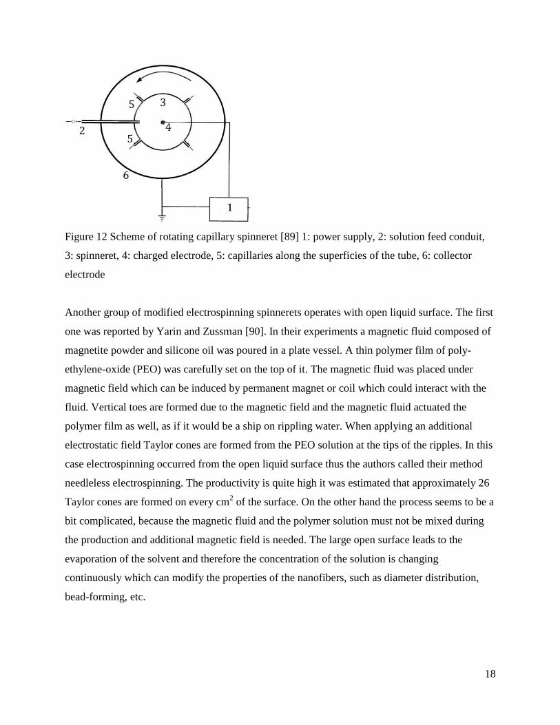
Andrady et al. [89] patented a spinneret configuration which also operates with a plenty of
capillary holes. The scheme can be seen in Figure 12.
Holes are located on a superficies of a cylinder and the collector is also cylindrical and concentric
with the spinneret. The solution can be fed into the spinneret through a conduit or even manually.
The flow rate can be regulated by adjusting the rotation speed and/or the pressure within the
spinneret tube. High output rates can be achieved, but the collector’s surface is limited or can be
extended only in a complicated way.
18
Figure 12 Scheme of rotating capillary spinneret [89] 1: power supply, 2: solution feed conduit,
3: spinneret, 4: charged electrode, 5: capillaries along the superficies of the tube, 6: collector
electrode
Another group of modified electrospinning spinnerets operates with open liquid surface. The first
one was reported by Yarin and Zussman [90]. In their experiments a magnetic fluid composed of
magnetite powder and silicone oil was poured in a plate vessel. A thin polymer film of poly-
ethylene-oxide (PEO) was carefully set on the top of it. The magnetic fluid was placed under
magnetic field which can be induced by permanent magnet or coil which could interact with the
fluid. Vertical toes are formed due to the magnetic field and the magnetic fluid actuated the
polymer film as well, as if it would be a ship on rippling water. When applying an additional
electrostatic field Taylor cones are formed from the PEO solution at the tips of the ripples. In this
case electrospinning occurred from the open liquid surface thus the authors called their method
needleless electrospinning. The productivity is quite high it was estimated that approximately 26
Taylor cones are formed on every cm2 of the surface. On the other hand the process seems to be a
bit complicated, because the magnetic fluid and the polymer solution must not be mixed during
the production and additional magnetic field is needed. The large open surface leads to the
evaporation of the solvent and therefore the concentration of the solution is changing
continuously which can modify the properties of the nanofibers, such as diameter distribution,
bead-forming, etc.
19
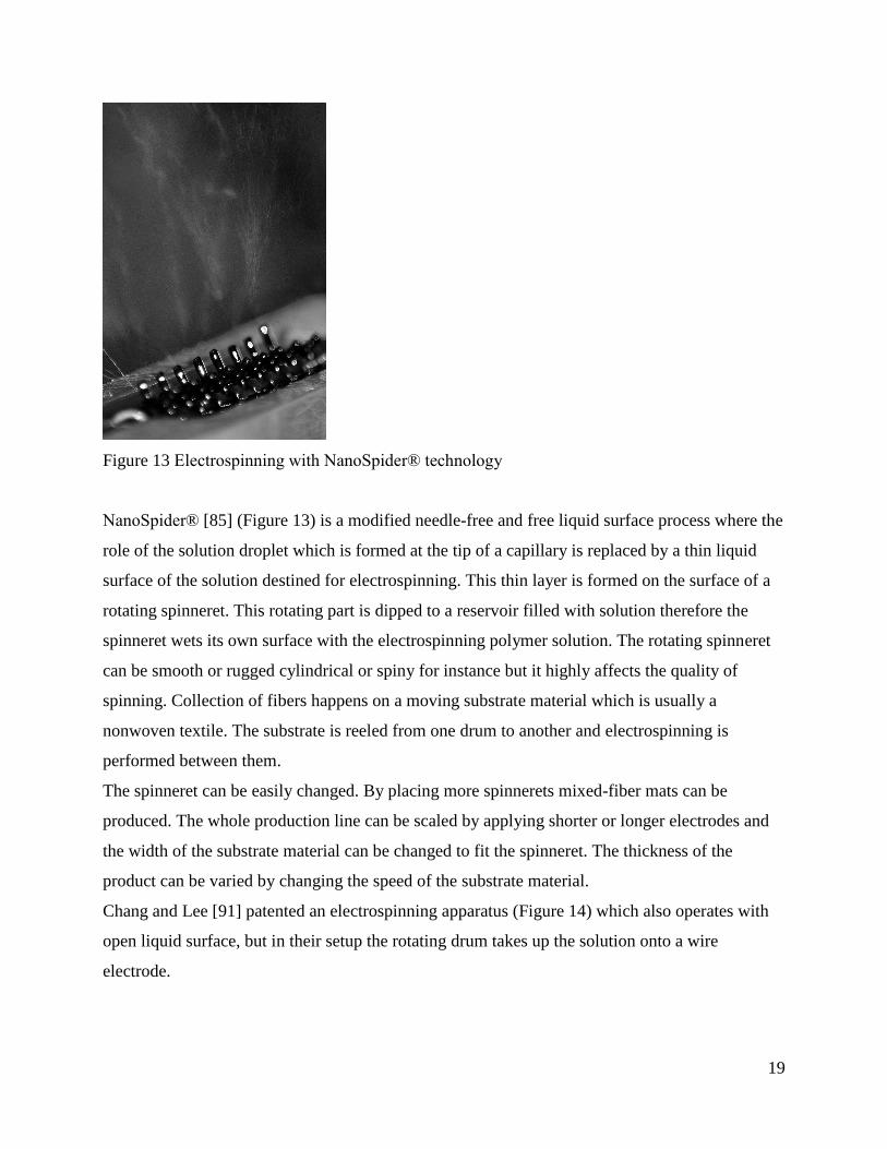
Figure 13 Electrospinning with NanoSpider® technology
NanoSpider® [85] (Figure 13) is a modified needle-free and free liquid surface process where the
role of the solution droplet which is formed at the tip of a capillary is replaced by a thin liquid
surface of the solution destined for electrospinning. This thin layer is formed on the surface of a
rotating spinneret. This rotating part is dipped to a reservoir filled with solution therefore the
spinneret wets its own surface with the electrospinning polymer solution. The rotating spinneret
can be smooth or rugged cylindrical or spiny for instance but it highly affects the quality of
spinning. Collection of fibers happens on a moving substrate material which is usually a
nonwoven textile. The substrate is reeled from one drum to another and electrospinning is
performed between them.
The spinneret can be easily changed. By placing more spinnerets mixed-fiber mats can be
produced. The whole production line can be scaled by applying shorter or longer electrodes and
the width of the substrate material can be changed to fit the spinneret. The thickness of the
product can be varied by changing the speed of the substrate material.
Chang and Lee [91] patented an electrospinning apparatus (Figure 14) which also operates with
open liquid surface, but in their setup the rotating drum takes up the solution onto a wire
electrode.

20
Figure 14 Electrospinning apparatus which operates with wire electrode [91], 1: Electrospinning
solution, 2: take-up drum, 3: wire electrode, 4: electrospinning space, 5: collector, 6: rotating
mandrel
Bubble electrospinning is also an interesting method. It was invented and reported by Liu and He
[92-94] in China, Smit and Sanderson in South Africa [95] and in USA by Reneker et al. [96] at
almost the same time in 2008. There are only few differences in the PCT submission dates. The
invention scheme drawn by Reneker can be seen in Figure 15 and Figure 16. Bubble
electrospinning can operate with even a static reservoir or with a rotating spinneret and moreover
the gas inlet can be diverse.

21
Figure 15 Bubble electrospinning setup with multiple gas inlets for mass production of nanofibers
[96]
Figure 16 Bubble electrospinning apparatus with a rotating spinneret [96]
Bubbles are produced on the surface of the spinning solution with the aid of air/nitrogen gas.
These bubbles are able to play the role of Taylor-cones. The fiber formation can principally be
affected by the size of bubbles, thus even 50 nm diameter fibers can be obtained. When the
bubbles crack it would not splash on the collector screen, but the altering surface during bubble
pop is also eligible for spinning fibers.
The charge injection method which was originally developed for electrospraying but it can also
be applied for electrospinning as patented by Kelly [97] and can be seen in Figure 17. It can be
applied for materials with poor conductivity, for example polymer melts. The liquid destined for
spinning is touched by two electrodes: a blunt one from outside and a tapered one which is
dipping in. The high voltage is connected with one of the electrodes while the other one is
grounded. Spinning is carried out with the aid of high pressure, for instance air flow, which
forces out the polymer material through the spinneret hole. No Taylor cone comes into existence,
but as the liquid is charged electrically, therefore the jet undergoes the same instabilities as in
case of the capillary electrospinning. The productivity of this spinning technique is 2 or 3 orders

22
of magnitude higher than that of the classical capillary electrospinning. The method is a kind of
hybrid of electrospinning and melt spinning techniques.
Figure 17 Scheme of charge injection electrospinning [97]
14.3.2 Modified collector systems for producing special electrospun structures
Composite materials have the advantage that the layup and fiber orientations can be well-
designed according to the appropriate loads.
In case of electrospinning the product is a fiber mat without any specific fiber orientation. It is
quite similar to microfibrous mats, but there are strong cross-linking points between fibers. It also
means that this material is quasi-isotropic. It also means that one of the main advantages of
composites is lost because the material can not be designed to fit the loads. There are several
methods which allow preparing uniform fiber structures contrary to quasi-isotropic mat structure
via electrospinning.
One dimensional electrospun structures can be created by stretching the nanofibrous fibers during
their generation. By stretching technique the diameter of the nanofibers can be reduced and
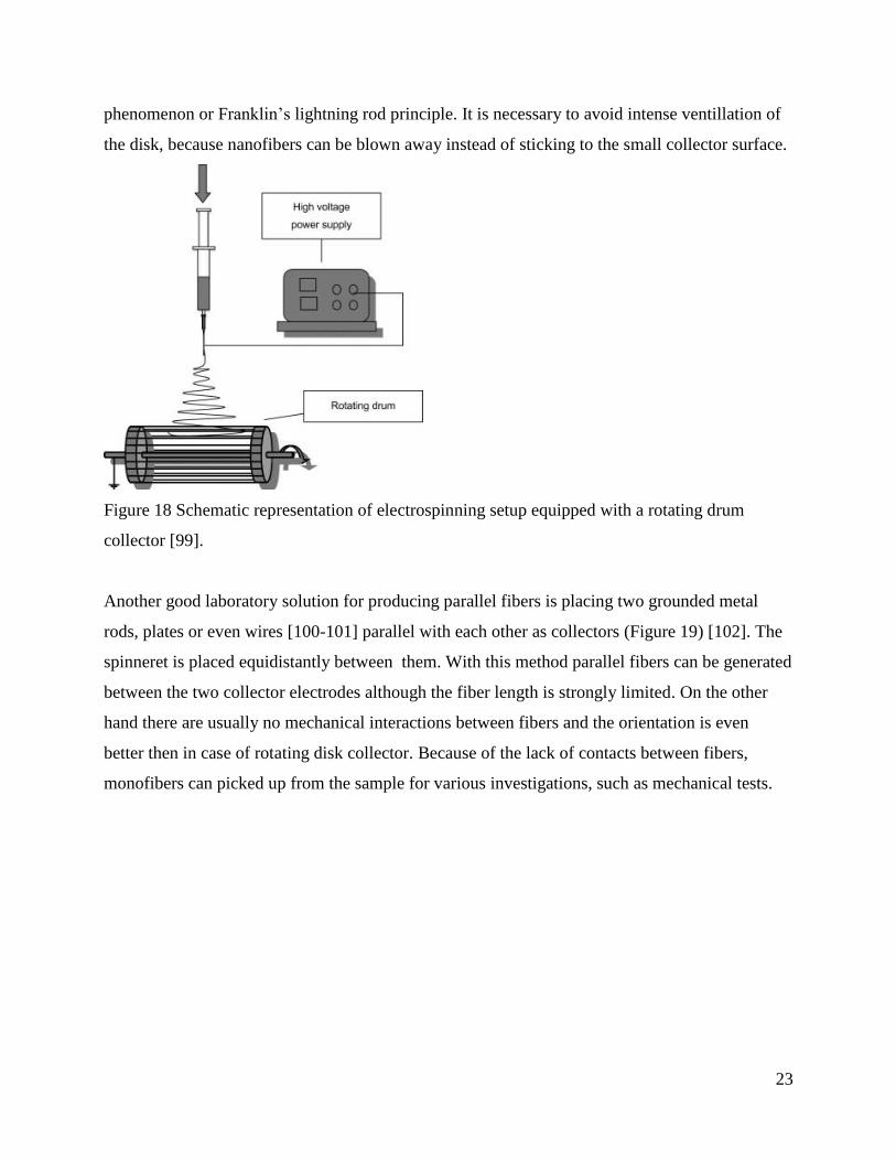
excellent orientation can be obtained [98]. A rotating disk or drum [99] (Figure 18) can be
applied as collector where fibers are deposited on the superficies. Although this technique is
simple it is very limited because yarns can be created only with a finite length. The most
important factors which affect fiber orientation are the circumferential rotational speed and the
width of the disk and the geometry of the edges are also important due to the coronal discharge
23
phenomenon or Franklin’s lightning rod principle. It is necessary to avoid intense ventillation of
the disk, because nanofibers can be blown away instead of sticking to the small collector surface.
Figure 18 Schematic representation of electrospinning setup equipped with a rotating drum
collector [99].
Another good laboratory solution for producing parallel fibers is placing two grounded metal
rods, plates or even wires [100-101] parallel with each other as collectors (Figure 19) [102]. The
spinneret is placed equidistantly between them. With this method parallel fibers can be generated
between the two collector electrodes although the fiber length is strongly limited. On the other
hand there are usually no mechanical interactions between fibers and the orientation is even
better then in case of rotating disk collector. Because of the lack of contacts between fibers,
monofibers can picked up from the sample for various investigations, such as mechanical tests.

24
Figure 19 Stretching of a charged jet segment across a pair of parallel electrodes [102].
Two ring electrodes can also be applied instead of rods. It is a very easy way to produce
nanofibrous yarns by rotating one of the rings by the desired number of twists after
electrospinning. The scheme and the realization of the system can be seen in Figure 20 and
Figure 21 [103].
Figure 20 Application of two ring electrodes for producing twisted nanofiber yarns [103].

25
Figure 21 Application of two ring electrodes for producing twisted nanofiber yarns in practice:
the produced oriented nanofibers before twisting [103].
As it can be seen through a few examples, there are several tricks which allow to produce linear
structures, but these practically can not be implemented to industrial scales. Different continuous
yarn-preparation methods are developed which can be classified into two different groups. The
first one consists of processes operating with special electrode geometries or spinning conditions,
while the members of the other group apply liquid collector systems.
Two, perpendicular rotating disks can be used as collector system [104] instead of one. In case of
two disks the fibers cannot stick to the first one and the other disk can continouosly wind up the
yarn. The orientation and twisting of fibers occurs between the drums. Potentially infinite twisted
yarn can be produced, with relatively high (approx. 10 m/s) haul-off.
A tip of a needle can focus fibers by the “lightning rod” principle. The focused jet of fibers would
not stick to the tip of the needle it is rather blown away. Fibers are twisted around one another
due to the whipping instability in a small space forming a yarn. This phenomenon is called self-
bundling in electrospinning literature [105]. Fibers can be reeled with the aid of an auxiliary
rotating drum to get continuous yarns or even with only one drum [92]. If the electrospinning
parameters are adequate the already twisted part of the forming structure can act as a needle-tip
and an automatic process is being started with further twisting and yarn formation. Continuous
yarns can be produced by conjugate electrospinning technique also. The fibers are produced from
two capillaries which are located in front of each other having the same axis but in different

26
directions. The parallel forming fibers from the two spinnerets twist each other as they contact,
resulting a yarn which can be reeled continuously.
Smit et al. [30] developed a method which uses open liquid (water for instance) surface to collect
nanofibers. The wet nanofibers are then pulled out of the liquid bath with a rotating drum. Fiber
orientation is formed when the nanofibrous mat leaves the bath resulting in a continuous yarn.
The scheme of the process can be seen in Figure 22 and the yarn formation mechanism from top-
view can be seen in Figure 23.

27
Figure 22 Yarn-spinning setup with water bath grounded collector electrode [30]
Figure 23 Top-view of the yarn formation process [30]
Teo et al. [29] developed a liquid support system which allows creating continuous yarns which
can be seen in Figure 24. Here the fibers are twisted due to the formation of a continuous vortex
of water in the upper tank. The liquid is continuously restored from the lower reservoir with the
aid of a pump. Twisted fibers are collected with a rotating mandrel therefore yarns can be
produced with potentially infinite length.
Figure 24 Schematic of the steps for the formation of yarn using a vortex [29]

28
14.4 Composite nanofibers
Nanofibers can be composites themselves if they are reinforced with smaller nanoparticles. On
the other hand they can be the reinforcement of mono- and hybrid composites. Some processing
techniques and applications of electrospun fibers are summarized in this subsection.
14.4.1 Testing and modeling the mechanical behavior of nanofibers for composite
applications
Determination of the tensile properties of nanofibers and structures built of
The mechanical performance of electrospun nanofibers concerning nanocomposites can be
discussed at different levels such as mechanical properties of single nanofibers, mechanical
properties of nanofibrous self-products, and nanofiber reinforced composites as well. When
designing composites it is crucial to know the mechanical parameters, behavior and damage
process of the nanofibrous materials.
Determination of the mechanical properties of nanofibrous mats and yarns is quite simple. In case
of mats, dumbbell specimens or even stripes can be cut and attached to paper frames by adhesive
tapes and tested by traditional tensile testers after removing the edge of the frames (see Figure
25).
Figure 25 Tensile tests carried out on nanofibrous mat samples. A: gripping the specimen, B:
cutting the edge of the frame, c: beginning of the test.

29
For determining the tensile properties, it is necessary to know the cross section of the specimens.
In case of electrospun materials which are deposited on a flat metal collector [106] the area
density is not uniform. To avoid this problem, it is suggested to use a rotating drum with low
velocity. This slow motion does not affect the orientation of fibers, but the structure has a quasi-
constant thickness in the direction of the rotation [107]. And in this case the linear density in the
direction of rotaion can also be considered constant. The cross section can easily be determined
by knowing the density of the bulk material, the weight and length of the sample [25,107]. When
testing nanofibers embedded in a matrix material, this method can also be used and paper frames
can even be discarded.
In case of single fibers the determination of tensile parameters are far more complicated. These
methods require special and also expensive apparatus, for example atomic force microscopy
(AFM), micromanipulators, etc. That is the reason why testing of nanofibers is usually limited to
the determination of geometrical or drug release properties [107]. For the determination of single
nanofibers it is suggested to produce oriented nanofibrous samples for instance with the ‘two
parallel rods’ collector configuration (Chapter 14.3.2). The sample can be attached to a paper
frame, and under a microscope, all fibers can be removed, but one. This single fiber then can be
manipulated for further experiments. Figure 26 shows a single fiber test setup designed for
determining the modulus of a single nanofiber within a chamber of SEM. The modulus of single
carbon nanofibers can be determined using the natural resonance vibration method where the
modulus-frequency relation is given from the classical linear elasticity [108].
As these methods are quite complicated, modeling can also be applied to determine the tensile
properties of nanofibers. The modeling method and software developed by Vas and Tamás [109]
were applied to determine the tensile properties of single nanofibers via experiments carried out
on nanofibrous Polyamide-6 (PA-6) mats. The modeling method was found to be appropriate
because the results were agreed well with the experimental results of Hwang et al. [110] who
measured the tensile strength of single PA-6 nanofibers by using nanomanipulator and AFM
cantilever in a SEM.

30
Figure 26 SEM image of a carbonized nanofiber clamped between an AFM tip and a tungsten
wire. A smaller AFM cantilever on the same AFM chip is present in the background [108].
As the damage of nanofibers happens due to the flaws of the material which are strongly related
to the volume and extent of nanofibers, e.g. Weibull-analysis can be used to describe the failure
characteristics [108].
Properties of nanofibers in respect of composite applications
Nanofibers have excellent flexural properties and high specific volume because of their small
diameters. In principle, disregarding the differences in tensile strength they may be used for
reinforcing at much smaller fiber content as compared to microfibers. For example, supposing
regular quadratic arrangement of fibers (Figure 27) and microfiber content of 50% the same
interfibrillar distance (here 12.5 m) that is the matrix layer thickness between micro- and
nanofibers of 10 and 0.1 m diameters, respectively, can be realized at a nanofiber content of
0.005 % which means a difference of 4 magnitudes.
Therefore it is a big challenge for scientists to develop nanofibers with appropriate tensile
properties as a primary reinforcement of PPCs. The idea to utilize nanofibers as reinforcement in
composites is based on very strong arguments. Their high surface compared to their volume
makes them able to make a strong adhesion with the matrix. If the critical fiber length is 1000
times more than the fiber diameter it still only means that a few hundred microns can be adequate
in length in case of continuous electrospun nanofibers, it can be seen that theoretically nanofibers

31
could still reinforce the composite and properly bear the stress even in case of a meager
compatibility between the fiber and the matrix.
a
a
d
L
a
Figure 27 Quadratic arrangement for studying the matrix vicinity and the distance between
reinforcing fibers
Nanofibers generally have a moderately higher tensile strength and modulus than the bulk or film
material due to the inner orientation of polymer molecules. Figure 28 [111] shows the E-moduli
of submicron fibers as a hyperbolic function of the fiber radius as usual concerning this
relationship. As fiber diameters are decreased somewhere below 300 nm, the tensile properties
also increase notably [110] and the nano-effect takes place.

32
Figure 28 The E modulus of nanofibers. Redrawn and reanalyzed by He et al. [111] according to
Gu and co-workers’ experimental data [112] shown by the dots.
It is believed that during the elongation of the liquid jet a very high molecular orientation is
formed, but the chains are relaxed during and after the evaporation of the solvent (solidification
of fibers) which leads to moderate inner orientation [113] and that is the reason why only very
thin fibers can have highly increased strength. WAXD (wide-angle X-ray diffraction)
experiments revealed that molecular chains are just moderately oriented within nanofibers and
the crystal structure did not change significantly compared to the film of the same material [114].
Gu et al. examined nanofibrous polyacrylonitrile (PAN) material by FTIR (Fourier transform
infrared spectroscopy). They found that the dichroic ratio significantly decreased from 1 for cast
film to 0.881 for aligned electrospun fibers and the orientation factor was also increased.
Zussman et al. [108] found that Herman’s orientation factor of carbonized nanofibers was 0.34. It
is a low value compared to the orientation factor of highly-oriented melt-spun fibers (0.6) and
wet-spun fibers (0.66).
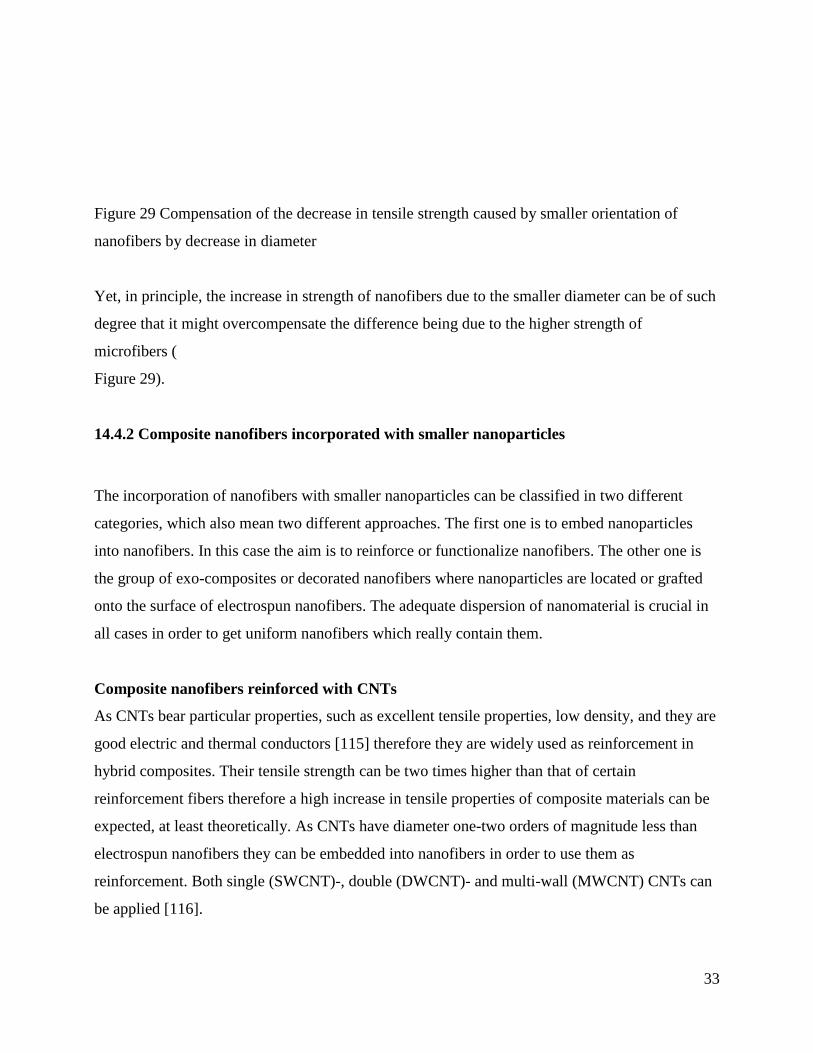
All in all the tensile strength and moduli of nanofibers are usually far lower than those of the
microfibers of the same material. The origin of the morphological difference can be attributed to
the different fiber drawing mechanisms. In case of microfibers the high inner orientation is
formed during the drawing and the solidification also befalls under mechanical tension thus the
high orientation remains along the fiber length unlike in case of nanofibers. Nanofibrous
structures cannot be drawn efficiently during solidification and relaxation of molecular chains
can be expected. The material can be subjected to mechanical post-drawing, but only in a
complicated way otherwise its structure, which is generally not composed of ideally parallel
fibers would be damaged.
B1=B2 High orientation
Lower orientation
Fiber diameter, d
Tensile strength
d3>d2>d1
B3
33
Figure 29 Compensation of the decrease in tensile strength caused by smaller orientation of
nanofibers by decrease in diameter
Yet, in principle, the increase in strength of nanofibers due to the smaller diameter can be of such
degree that it might overcompensate the difference being due to the higher strength of
microfibers (
Figure 29).
14.4.2 Composite nanofibers incorporated with smaller nanoparticles
The incorporation of nanofibers with smaller nanoparticles can be classified in two different
categories, which also mean two different approaches. The first one is to embed nanoparticles
into nanofibers. In this case the aim is to reinforce or functionalize nanofibers. The other one is
the group of exo-composites or decorated nanofibers where nanoparticles are located or grafted
onto the surface of electrospun nanofibers. The adequate dispersion of nanomaterial is crucial in
all cases in order to get uniform nanofibers which really contain them.
Composite nanofibers reinforced with CNTs
As CNTs bear particular properties, such as excellent tensile properties, low density, and they are
good electric and thermal conductors [115] therefore they are widely used as reinforcement in
hybrid composites. Their tensile strength can be two times higher than that of certain
reinforcement fibers therefore a high increase in tensile properties of composite materials can be
expected, at least theoretically. As CNTs have diameter one-two orders of magnitude less than
electrospun nanofibers they can be embedded into nanofibers in order to use them as
reinforcement. Both single (SWCNT)-, double (DWCNT)- and multi-wall (MWCNT) CNTs can
be applied [116].

34
Generally the most profitable dispersion method is to mix the nanoparticles to the solvent then
add and mix to the polymer destined for electrospinning. For example Hou et al. [117] mixed
SWCNTs in DMF with bath sonication. The process took 12h to reach adequate dispersion. After
ultrasonication they added the polymer and stirred further for 12h by using magnetic mixer. Hou
et al. [117] pointed out that if the CNT concentration is too high the fibers surface is rough. It is
because CNTs are not completely embedded in the fiber in this case. TEM micrographs of CNT
embedded polyamide fibers can be seen in Figure 30[118].
Figure 30 TEM micrographs of (a) CNT reinforced nylon 6,6 fibers showing the agglomeration
of CNTs. The CNTs were dispersed in the nylon 6,6 polymer solution; and (b) CNTs are
embedded in the core region of the fiber and are aligned along the fiber axis [118].
Well-dispersed nanotubes are oriented along the nanofibers axis and in specific cases they
increase the molecular orientation. The conductivity of CNT-loaded nanofibers is significantly
increased [119-120].
The mechanical properties of nanofibrous materials can significantly be improved by embedding
CNTs. The electrospun fibers which contained 0.75 wt% SWCNTs had nearly 60% higher tensile
strength and more than 60% higher modulus than that of the reference material [117].
It is possible to produce composite nanofibers by an industrialized and cost-effective way as
Kostakova et al. [121] did via needleless electrospinning from PVA (Poly-vinyl alcohol),
crosslinking agents and applied either MWCNTs or SWCNTs as a nano-reinforcement of the
nanofibers. It is not obvious whether CNTs are embedded in the fibers in case of needleless
electrospinning, because there is no such continuous flow through a capillary which assures the
35
CNTs flow with the liquid jets of electrospinning. They carried out Raman spectroscopy and
pointed out that CNTs are located within the fibers spun from the open liquid surface.
There are several other types of carbons which can be embedded in fibers, such as carbon black
[25], exfoliated graphite [122] and there are other types of nanoparticles, such as montmorillonite
[122-124], metal nanoparticles [125], nano-silica [126], etc. but these latter ones are not strongly-
related to PPCs.
Exocomposite polymer nanofibers
Another group of composite nanofibers are decorated or exocomposite nanofibers which are
particularly developed for biomedical and sensor applications. The nanoparticles are located at
the surface of nanofibers which can lead to ultra-fast drug release, but do not play reinforcing
role.
Exocomposite nanofibers can be processed by different methods. E.g. nanoparticles are
electrosprayed on the forming fibers. The other possibility is to carry out electrospinning in a
dusty environment. Nanoparticles can be stuck to the surface of the forming nanofibers the same
way. The amount of nanoparticles can be adjusted by the flow rate or density of the nanoparticles
in the spinning space, respectively.
A wide variety of nanoparticles can be processed, and there are other methods also, for example
physical or chemical vapor deposition can be used for metal particles. Exocomposite fibers can
also be produced via wet methods where nanoparticle coating is obtained by immersing
nanofibrous mats into a liquid containing nanoparticles. It is also especially used for metal
nanoparticles. These other solutions which are not strongly related to polymer-polymer
composites are reviewed by Andrady [25].
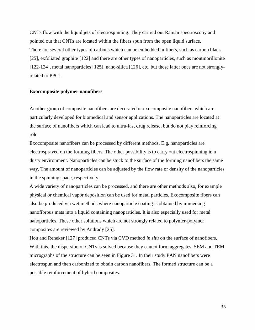
Hou and Reneker [127] produced CNTs via CVD method in situ on the surface of nanofibers.
With this, the dispersion of CNTs is solved because they cannot form aggregates. SEM and TEM
micrographs of the structure can be seen in Figure 31. In their study PAN nanofibers were
electrospun and then carbonized to obtain carbon nanofibers. The formed structure can be a
possible reinforcement of hybrid composites.
36
Figure 31 TEM (A) and SEM (B) micrographs of CNTS on carbon nanofibers [127].
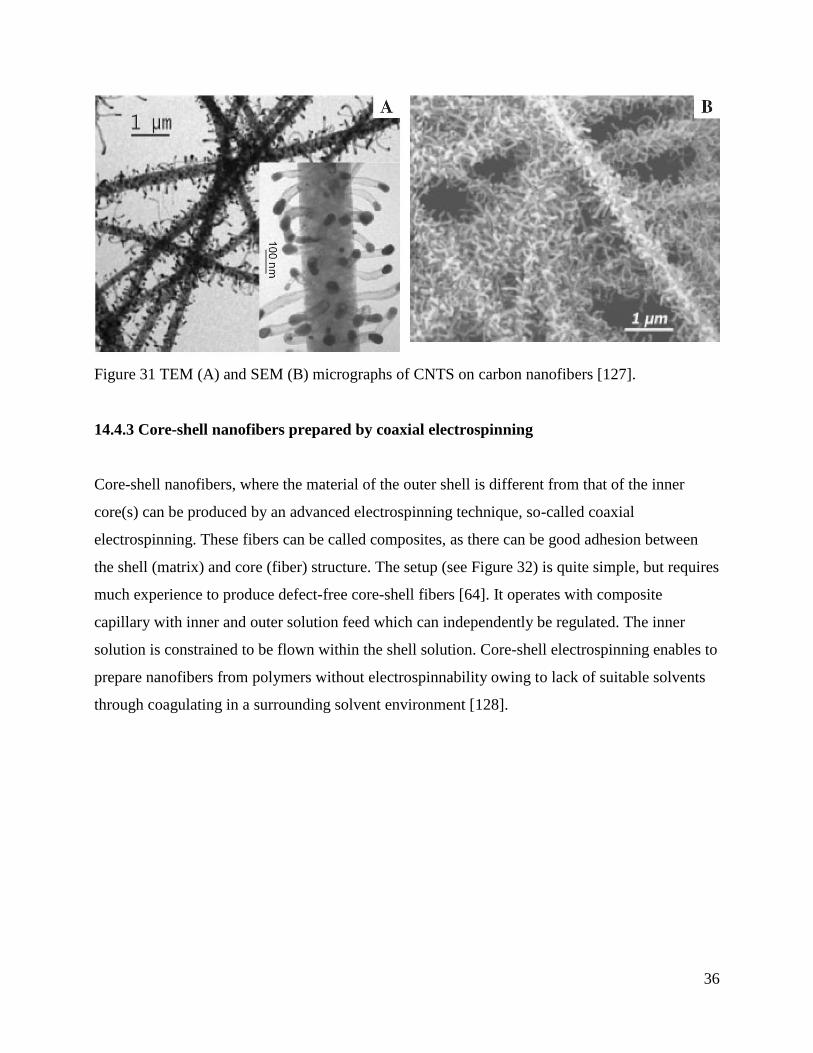
14.4.3 Core-shell nanofibers prepared by coaxial electrospinning
Core-shell nanofibers, where the material of the outer shell is different from that of the inner
core(s) can be produced by an advanced electrospinning technique, so-called coaxial
electrospinning. These fibers can be called composites, as there can be good adhesion between
the shell (matrix) and core (fiber) structure. The setup (see Figure 32) is quite simple, but requires
much experience to produce defect-free core-shell fibers [64]. It operates with composite
capillary with inner and outer solution feed which can independently be regulated. The inner
solution is constrained to be flown within the shell solution. Core-shell electrospinning enables to
prepare nanofibers from polymers without electrospinnability owing to lack of suitable solvents
through coagulating in a surrounding solvent environment [128].
37
Figure 32 Coaxial electrospinning basic setup and the formation of Taylor cone [64]
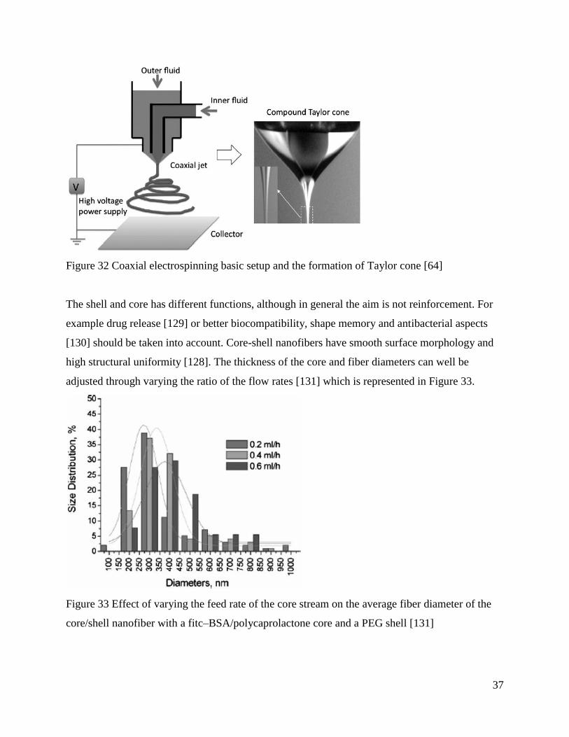
The shell and core has different functions, although in general the aim is not reinforcement. For
example drug release [129] or better biocompatibility, shape memory and antibacterial aspects
[130] should be taken into account. Core-shell nanofibers have smooth surface morphology and
high structural uniformity [128]. The thickness of the core and fiber diameters can well be
adjusted through varying the ratio of the flow rates [131] which is represented in Figure 33.
Figure 33 Effect of varying the feed rate of the core stream on the average fiber diameter of the
core/shell nanofiber with a fitc–BSA/polycaprolactone core and a PEG shell [131]

38
In several cases the aim is to eliminate the core from the fibers and gain nanofibers with hollow
conduits inside or with simple holes. SEM images of core-shell fibers prepared by coaxial
electrospinning can be seen in Figure 34. The other option is to create beaded fibers where the
beads are porous [81]. Presently these are not strongly-related to composite applications.
Figure 34 Cross sections of hollow fibers prepared by coaxial spinning having two, three, four
and five channels, respectively. The scale bars are 100 nm [64]
Composite nanofibers with for example CNT loading can also be prepared via coaxial
electrospinning, where high concentration of CNTs can be embedded [132]. Kim et al. [133]
produced PAN nanofibers by coaxial electrospinning and combined the technology with
decoration of fibers with palladium and forming small holes within fibers with water vapor. The
fibers were then heat-treated to obtain carbon nanofibers. These materials can be used as fuel
cells and had a specific surface area of more than 800 m2/g. Nagamine et al. [134] produced
carbon-core/TiO2-sheath nanofibers with diameters of a few hundred nanometers and sheath
thicknesses of tens of nanometers by coaxial electrospinning. This material has an excellent
conductivity and could be used in functional of composite applications as well.
14.5 Synthetic polymer-polymer composites containing or based on electrospun nanofibers

39
Classical SPPCs can further be incorporated with nanofibers, in order to get hybrid composites.
The nanofibrous structure can modify their interlaminar properties or even other properties to get
functionalized hybrids for specific applications. On the other hand nanofibers can be the primary
reinforcement of composite materials. This subsection summarizes the potential of nanofibers in
nanocomposites.
14.5.1 Nanofibers as interlaminar reinforcement of composites
The interlaminar properties of laminated thermosetting composites can often become their
dominating weakness. E.g. laminated composite parts must have adequate interlaminar shear
strength to avoid damage such as delamination, buckling, and peeling.There are several ways
developed to increase the interlaminar shear strength, such as physical blending, placing special
thin films [135-137] or CNTs [138-140] between laminate layers, etc. but these solutions usually
modify the geometry and increase the weight of laminates. Stitching, Z-pinning or other methods
can be applied to clench the layers but these can cause fiber breaks of the primary reinforcement
of the material and also generate additional costs.
The idea of incorporating and placing small diameter fibers within microfibrous reinforcement
layers was patented by Dzenis and Reneker [141] in 2001. Their invention is not limited to any
particular matrix type, therefore nanofibers can be used both in thermosetting and thermoplastic
matrices, theoretically. The small diameter fibers (typically electrospun nanofibers) can be
applied at one or more ply interfaces or at a portion thereof and provide improved interlaminar
toughness, strength, and delamination resistance without substantial reduction of in-plane
properties and without substantial increase in weight. They intercalated graphite/epoxy
unidirectional prepregs with polybenzimidazole (PBI) electrospun fibers and reported 15%
increase in the Mode I and 130% improvement in the Mode II critical energy release rates.
Nanofibers can be generated by using a plate collector or by spinning them directly onto the
surface of the reinforcement fabric or prepreg. In the first case the electrospun fibers must be
removed from the collector surface carefully, for example by washing. Figure 35 shows a
unidirectional carbon fabric partly coated by electrospun nanofibers.

40
Figure 35 Unidirectional carbon reinforcement coated with nanofibers (left) and without coating
(right) [142]
The latter method is favorable because the nanofibrous mat (which sometimes has an area density
of only 1 g/m2 or less) in this case will not be damaged during transport or processing which is
especially important in industrialization. According to other considerations there is no need to use
release agent between the collector and the nanofibrous mat because the collector is the
reinforcement material. If metal mould is used for laminating the composite part or product and
the fibers have enough conductivity (which is ture for example for carbon nanofibers) then
electrospun interlaminar layers can be produced in situ during the layup. The spinneret should be
moved along the mould to have an even nanofibrous coating on the whole interfacial surface.
Robots can even be used for automation.
The coating can be done before the product preparation, and before the pattern making, where the
reinforcement is available in roll or in tow formats. In this case the reinforcement material is re-
wound between two rollers and electrospinning happens in-between by using stationery spinneret
electrode(s). Therefore there is some technological flexibility: production of nanofibrous
interlayers can be taken upon by both the fiber manufacturer and the composite product
manufacturer.
Beyond the good automation possibilities the most important difference between the two
approaches which emphasize the efficiency is that nanofibers can twist and encompass

41
microfibers (see Figure 36). Nanofibers can act as anchors of microfibers after impregnation,
resulting in better shear performance [142].
Figure 36 Scanning electron micrograph of carbon micro- and PAN nanofibers [142]
According to the experiences in this field, it is crucial to impregnate well the nanofibers.
Although nanofibrous mats have a high porosity and the wetting of the resin is often adequate,
heed must be given to the small size of the micro- and nanopores which can require high pressure
to be filled with resin [142]. It is recommended to use vacuum or pressure for impregnation to
eliminate bubbles and cavities. There are different, simple methods for better impregnation, such
as vacuum pressing [142], vacuum bag technology [143], using autoclave for curing [144],
VARTM, H-VARTM [145], etc.
Zhang [146] et al. investigated the effect of the thickness of the nanofibrous interleaves and the
effect of nanofiber diameters on the Mode I fracture toughness, flexural and DMTA properties.
They investigated carbon fiber fabric reinforced epoxy composites with approx. 0.2-0.7 wt%
polyetherketone cardo (PEK-C) toughening.
Finer nanofibers resulted in better improvement in the interlaminar properties without
compromising the in-plane performance of the toughened composites [146], thus decreasing the
fiber diameters is favorable. It must be noted that the increase in Gic-INI (critical energy release
rate for crack initialization) was increased primarily due to the presence of nanofibers and the
effect of fiber diameters had only secondary, minor effects. The smallest fiber diameter they

42
investigated was 450 nm but nanofibers strength typically increases significantly under 300 –
200, nm of which we do not have experience, only predictions.
The thickness of nanofibrous toughening layer had a significant effect on crack initiation and
propagation properties. Figure 37 shows the critical energy release rates as a function of the
thickness of nanofibrous interleaves. The critical energy needed for crack initiation and for crack
propagation are increased considerably, by approx. 60% and 80%, respectively in the case of 70
and 105 µm thicknesses.
Figure 37 Effect of the thickness of nanofibrous interleaves on the crack initiation and
propagation behavior [146]
Increasing the thickness even more can have negative outcome. For instance Liu et al. [143]
found that approximately, when the sum of the thickness of nanofibrous toughening layers
reaches one tenth of that of the composite the flexural modulus and the interlaminar shear
properties began to drop. When increasing the amount of nanofibers this effect becomes even
heavier.
Different nanofibrous interlaminar layers in the same composite material can lead to different
toughening effects. Liu et al. [143] investigated this problem by applying a rigid, general
thermoplastic and elastomer nanofibers. The rigid one increased the tensile modulus
considerably, while the elastomer helped more in toughening and lead to lower modulus. It gives
the opportunity to adjust the mechanical performance of composites by choosing the adequate

43
toughening material. On the other hand the exact amount which gives the best toughening is
unknown in these days.
Kelkar et al. [145] investigated the Mode I fracture toughness of glass fiber reinforced
composites incorporated with tetra-ethyl-orthosilicate (TEOS) nanofibrous interlayers and
alumina nanoparticles. They found no significant improvement, however only one interlaminar
layer was placed between 10 layers of glass fabric. On the other hand they experienced
significant increase in GIC in case of alumina nanoparticles. Nanoparticles can also be constructed
from nanofibers, through phase-separation.
Polysulfone (PSF) is used as an interlaminar toughener in film form [147], acting through the
mechanism of reaction-induced phase separation. The film between the layers forms small
(several micron sized) spheres and sea-island morphology can be obtained. Li and his co-workers
[148-149] had the idea to utilize this phenomenon in case of nanofibers and created polysulfone
nanofibrous mats on the surface of carbon fiber reinforced epoxy prepregs because they
presumed that the phase separation occurs in the same way as in the case of nanofibers. They
prepared composite laminates by hot pressing the prepregs at 130°C for 2h, 180°C for 2h and
200°C for another 1h. The composite coupons had a PSF nanofiber content of 1 wt%, 3 wt% and
5wt%. They investigated the morphology via SEM, and the Mode I fracture, DMTA and 3-point
bending properties of the samples taken from the coupons. The found that the due to the high
porosity of nanofibrous mats they could be well-impregnated and on the fracture surface it can be
seen that complete phase-separation occurred during the curing at high temperatures. They found
PSF spheres with diameters of 2-6 µm, with uneven distribution. It can be attributed to the high
scattering of nanofiber diameters. They concluded that the Mode I interlaminar fracture
toughness (GIC) which means the magnitude of adsorbed energy for crack propagation and which
is related to the morphology of the laminate was higher in case of nanofiber-reinforces
composites than in case of PSF films and also higher than in the reference sample without any
interlaminar layer (reference material). They found 158%, 261% and 281% increase in case of
the 1 wt%, 3 wt%, 5 wt% sample compared to the reference material and 132%, 150%, 140%
compared to the PSF film toughened composite samples. The flexural properties were slightly
increased but not in case of the 5 wt% sample.
Dynamic mechanical thermal analysis (DMTA) showed that the Tgs (glass transition
temperatures) of the PSF nanofiber mat toughened composites were slightly higher which can be
44
attributed to the better cross-linkage of a part of the epoxy/amine molecules resulting in better
compatibility between the matrix and PSF nanofibers than in case of applying PSF films instead.
It can be concluded that the thickness of nanofibrous layer somehow again affects the properties
considerably. In this case the 3 wt% sample gave the best results.
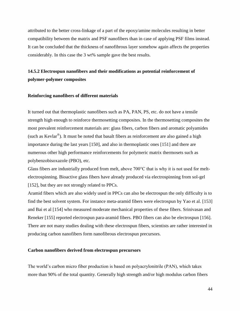
14.5.2 Electrospun nanofibers and their modifications as potential reinforcement of
polymer-polymer composites
Reinforcing nanofibers of different materials
It turned out that thermoplastic nanofibers such as PA, PAN, PS, etc. do not have a tensile
strength high enough to reinforce thermosetting composites. In the thermosetting composites the
most prevalent reinforcement materials are: glass fibers, carbon fibers and aromatic polyamides
(such as Kevlar®). It must be noted that basalt fibers as reinforcement are also gained a high
importance during the last years [150], and also in thermoplastic ones [151] and there are
numerous other high performance reinforcements for polymeric matrix thermosets such as
polybenzobisoxazole (PBO), etc.
Glass fibers are industrially produced from melt, above 700°C that is why it is not used for melt-
electrospinning. Bioactive glass fibers have already produced via electrospinning from sol-gel
[152], but they are not strongly related to PPCs.
Aramid fibers which are also widely used in PPCs can also be electrospun the only difficulty is to
find the best solvent system. For instance meta-aramid fibers were electrospun by Yao et al. [153]
and Bai et al [154] who measured moderate mechanical properties of these fibers. Srinivasan and
Reneker [155] reported electrospun para-aramid fibers. PBO fibers can also be electrospun [156].
There are not many studies dealing with these electrospun fibers, scientists are rather interested in
producing carbon nanofibers form nanofibrous electrospun precursors.
Carbon nanofibers derived from electrospun precursors
The world’s carbon micro fiber production is based on polyacrylonitrile (PAN), which takes
more than 90% of the total quantity. Generally high strength and/or high modulus carbon fibers

45
are PAN or pitch-based, while in case of nanofibers the former one is far more popular although
there are attempts to create carbon nanofibers from metaphase pitch, but they usually have a
diameter of several microns [157-158].
For carbon fiber manufacturing the PAN base material is copolymerized, in most cases with
methyl methacrylate. In the electrospinning literature both PAN homopolymer and copolymer are
used. The applied solvent of PAN is commonly N,N-dimethylformamide (DMF) [108] but other
solvents can also be used, such as dimethylsulphoxide [159].
The precursor material is produced by electrospinning method and can have different formats:
such as yarn, mat, etc. Nanofibrous PAN precursor yarn can be seen in Figure 38.
Figure 38 SEM micrograph of PAN precursor yarn
The optimal precursor material consists of fibers which are defect-free and should be continuous
for industrial purposes. The solution and electrospinning process should be optimized considering
the parameters affecting fiber quality, such as concentration, applied voltage, etc. [160-161].
Carbon fibers are prepared from the precursor fibers through thermo-chemical reactions. The first
phase is stabilization under oxygen atmosphere, then follows carbonization under inert gas
atmosphere at higher temperature and finally graphitization follows at even higher temperatures.
In case of nanofibrous precursors this method is practically the same but pyrolysis parameters are
different.

46
The pyrolization of nanofibers is not a fully-developed field. The temperature of stabilization is
usually between 200 and 350°C and then carbonization and graphitization (optional) takes place
somewhere between 700 and 1500°C, but sometimes this interval can be even higher, between
500 and 3000°C [159].
There are different approaches, for instance Dhakate et al. [162] stabilized PAN in air atmosphere
and under stretching, at 275 and 320°C. The stabilized fibers were carbonized so that the
temperature was raised slowly from 550 up to 1000°C in nitrogen atmosphere. Zussman et al.
[108] stabilized PAN precursors for 30 min at 250 °C, carbonized in nitrogen fog 1h at 750°C
and graphitized at 1100°C for another 1h. The ramp rate between the 250, 750 and 1100°C
plateaus was 5°C/min. Zhou et al. [163] stabilized PAN nanofibrous yarns with a heating rate of
2°C/min up to 280°C and holding it for 3 h. Carbonization followed at 1000°C with the same
heating rate. The final carbonization (graphitization) followed in vacuum at 1400, 1800 and
2200°C, respectively with a heating rate of 5°C/min. It can be concluded that there is no standard
approach.
Similarly to carbon microfibers it is profitable to increase the final graphitization temperature
because the carbon nanofibers become more graphitic and structurally ordered [164] which is
reflected by increased tensile properties. The graphitic structure of PAN-derived carbon
nanofibers can be seen in Figure 39 [165].
Figure 39 TEM images showing the graphitic structures in GCNFs made from electrospun PAN
nanofiber bundles with phosphoric acid [165]

47
The nitrile groups in electrospun PAN nanofibers have a higher reactivity compared to micro
fibers and the structural conversion occurs faster in the stabilization phase [113] therefore
stabilization time is shorter than in case of microfibers.
The thermal behavior of the nanofibrous precursor made from PAN copolymer was investigated
by Dhakate et al. [162]. It was found that during differential scanning calorimetric (DSC)
experiments the nanofibers behave differently as compared to microfibers of the same material.
Microfibers and films have one exothermic peak which indicates the cyclization of nitrile groups,
formation of the ladder-like polymeric structure. On the contrary, nanofibers have two separate
peaks. The first one is similar to the peak that observed in case of micro fibers and films (at
275°C), but there is a second one, which is at a higher temperature (317°C) have a higher
intensity which can be seen in Figure 40.
Figure 40 DSC curve of (1) micron size PAN-CP fiber, (2) thin film of PAN-CP solution, and (3)
electrospun PAN-CP nanofibers [162].
It can be attributed to the difference in their surface to mass ratio. In case of nanofibers the
chemical reactions are somehow not completed at the first peak. Liu et al. [113] have also
compared the DSC curves of PAN microfibrous precursor of a carbon fiber manufacturer with
nanofibrous mat of the same base material. They also found one peak in case of microfibers and
two separated ones for electrospun material. It means that in case of nanofibers there are two

48
different types of thermo-chemical reactions. They concluded that it can be ascribed to the
discrepancies in macromolecular conformations and packing structures. In case of highly-
stretched microfibers the molecules are highly extended which makes the intra-molecular
cyclization among neighboring nitrile groups dominant during the early stages of the stabilization
process. Due to the low activation energy of this type of thermo-chemical reaction it happens at
lower temperature. On the other hand electrospun fibers contain a significant percentage of
molecules having helical conformations with nitrile groups being located on the outside of the
helices. It is because relaxation of chains happens before the solvent totally evaporates during
electrospinning and thermodynamically these helices are favorable, so the relaxed structure
would be like that. In case of this conformation the intra-molecular cyclization is hampered. The
intra-molecular cyclization has higher activation energy and occurs at higher temperature. That is
the reason why a second dominant peak appear on the DSC curves. Gu et al. [114,166] also
measured the DSC behavior of PAN nanofibers spun form homopolymer. They have found only
one peak, but it was shifted to a slightly lower temperature. They concluded that in case of
nanofibers the cyclization can be initiated easier.
The adequate copolymerization is a key problem in order to avoid degradation during the
oxidative stabilization of nanofibers. The specific exothermic heat energy which can lead to a
sudden degradation our burn of nanofibers instead of stabilization was found to be one order of
magnitude higher in case of PAN nanofibers than in case of films and microfibers of the same
material [162]. Moreover, it was found in TGA experiments, that PAN nanofibers are especially
sensitive for temperature-induced degradation (see Figure 41).

49
Figure 41 TGA curve of (1) PAN-CP micron size fiber, (2) film made from PAN-CP solution, (3)
PAN-CP nanofibers from 5 wt.% solution, (4) PAN-CP nanofibers from 7.5 wt.% solution, and
(5) PAN-CP nanofibers from 10 wt.% solution [162].
To increase the tensile properties, hot-stretching can be applied to PAN fibers [117]. Hou et al.
used PAN copolymer where the co-monomers were methyl acrylate (5.3 w%) and itaconic acid
(1.7 w%) and SWCNTs were mixed to the solutions in different concentrations between 0 and
1%. At first they electrospun a nanofibrous mat precursor then it was hot-stretched at 135°C for 5
minutes. For this both ends of the stripe-shaped nanofibrous mat were clamped. One end was
fixed to the ceiling of the oven while on the other ending there was a weight to induce the desired
tension. Hot-stretching increased crystallinity from 11% up to 38% and also the crystallite size
grew from 4 nm to 11 nm. The tensile strength was improved by 55% and the modulus had an
even higher improvement of 156%. On the other hand hot-stretching slightly increased the
exothermic heat during the stabilization which is, emphasized again, crucial to be minimized not
to degrade nanofibers instead of stabilizing them.
The higher weight losses can possibly be attributed to entrapped and residual solvents between
polymeric chains. Although it means that higher weight loss is not necessarily a problem, but at
the same time it can lead to a higher shrinkage of fibers during stabilization and carbonization.
The higher shrinkage can possibly lead to the realignment of the nanofibrous structure as well as
to other morphological changes.
It was found that although fibers shrank, their morphology did not alter [162]. The final diameters
of carbon nanofibers were in the range of 75-100 nm, which is approximately the half of the
diameter of the precursor. Moon and Farris [164] reported 55-59% decrease of fiber diameters
after carbonization. Zussman et al. [108] also experienced similar, 50% decrease in diameter after
carbonization. Gu et al. [166] found that the shrinkage after the carbonization was 25% in
diameter, and as the pyrolization process had different parameters in all cases, thus these
parameters can somehow be closely related to the morphological changes, shrinkage and weight
loss. Kurban et al. [159] revealed that adequate stabilization is very important to avoid high
weight losses and on the other hand the final graphitization temperature can significantly affect
the final fiber diameter through shrinkage and weight loss. They also found that the final
graphitization temperature can affect the surface morphology of carbon nanofibers. The surface

50
was found to be smooth in case of 1500°C and graphitizing at higher temperature (3000°C)
resulted in rougher, and more ridged surface which can also be seen in Figure 42 [159].
Figure 42 SEM images of heat treated non-oxidized fibres: (a) HTT = 1500 °C, (b)
HTT = 2800 °C, and oxidized fibres (c) HTT = 1500 °C and (d) HTT = 2800 °C [159].
The resulting carbon nanofibers can have a rough and pitted surface which can be assigned to the
vapor pressure of the solvent [166]. The size of pits was about 5 nm in width and 10 nm in length
on the surface of the investigated carbon nanofibers. Dhakate et al. [162] measured the surface
roughness of electrospun carbon nanofibers by using scanning probe microscopy (SPM) which
was found to be 27.0 nm, which is about 10 to 20 percent of the fiber diameter. This kind of
roughness can be an advantage, because the specific surface is further increased which is
favorable for good adhesion and functionalization. The surface roughness is also typical for
carbon microfibers which are derived from wet-spun precursors [113] (Figure 43 [167]).
Zussman et al. [108] found that crystalline sheets were oriented radially in the skin which has a
thickness of approximately 10 nm, but in the core of the fibers it formed a random-granular
structure. Aggregations of elongated crystals could be found parallel to the fiber axis which is a
preferable structure. Carbon microfibers can also have this typical core-shell structure.

51
Figure 43 Carbon nanofibers (a) FE-SEM images of the fractured surface of carbon nanofibers.
(b) The nanofibers were broken during sonication in an ultrasonic bath [167].
The mechanical properties of these carbon nanofibers neither exceed nor even approximate the
properties of microfibers. Although the strength of the classical microsized PAN precursors is
one order of magnitude larger than that of PAN nanofibers oxidizing and carbonizing them
makes this difference significantly smaller.
Moon and Farris [164] produced PAN co-polymer yarns in a finite length with different degrees
of alignment. They applied tension during stabilization and carbonization. The yarn samples were
drawn at different temperatures. They concluded that the drawing temperature should be above
Tg and the best results were got at 155-160°C (approximately 60°C above Tg).
It should be mentioned that the diffusion rate transfer in nanofibers would be hundred times faster
than in case of industrial microfibers, because diffusion is related to the inverse square of the
dimensions (fiber diameter).
Zussman et al. [108] measured the mechanical properties of single carbon nanofibers by the way
introduced in subsection 14.4.1. The average bending modulus of nanofibers were 63 ± 7 GPa
and the failure stress was between 0.32 and 0.9 GPa, where failure occurred at the gauge region.
The carbon fibers were prepared from PAN homopolymers, which is not easy to compare with
carbon microfibers based on PAN copolymers. They also carried out Weibull-analysis which
gave a failure stress of 640 MPa where 63% of nanofibers would break with a confidence interval
of 95%.
Zhou et al. [163] also measured the tensile properties of carbonized PAN yarns. The 1000°C
carbonized bundle had a tensile strength of 325 ± 15 MPa and a modulus of 40 ± 4 GPa. These
52
values are increased to 542 ± 45 and 58 ± 6 GPa, respectively with the increase of the final
graphitization temperature to 2200°C. These values are measured for the bundle which can differ
from the properties of single fibers to a great extent.
Moon and Farris [164] investigated different carbonization parameters in case of yarn samples
and the best one resulted an ultimate strength of approximately 1 GPa, but this value was
increased to 1.7 GPa when they impregnated the yarn with an adhesive. The problem with the
nanofibrous structure is that no single fibers can easily be tested. The tensile properties of single
fibers can be estimated from the tensile properties of the product for example by modeling (see
subsection 14.4.1). Single fibers can even have approximately 3 times higher tensile strength than
nanofibrous mats which are built up of the same single fibers [107]. In case of the experiments of
Moon and Farris [164] the adhesive blocked the slippage of nanofibers and this is the reason why
higher tensile values were got. The twisting of nanofibrous yarns which would also clog the
slippage surprisingly led to a decrease in the tensile properties. Finally, SEM micrographs
showed there were more broken fibers within the yarn samples which could cause a drop in
strength.
Zhou et al. [163,165] concluded that the electrical conductivity of carbon nanofibers were
approximately 180 S/cm parallel and 8 S/cm perpendicular to the fiber axis. This difference is
because the carbon fibers are continuous but in the perpendicular direction there are only small
contacts between them. The conductivity of the bundle strongly depends on the
contacts/entanglements among nanofibers. Increasing final graphitization temperature can
strongly affect conductivity through improved graphite structure. By increasing the temperature
from 1000°C up to 2200°C resulted 3.6 times higher in parallel and 7 times higher conductivity
in perpendicular directions.
Beside composite applications of electrospun carbon nanofibers, these materials can be used as
filter media also and can be applied to remove disinfection byproducts from water [168], for gas
separation, solvent recovery and catalyst support [169]. These activated carbon nanofibers have
low pressure-drop compared to granular activated carbon.
14.6 Conclusions and outlook
53
Electrospinning gained a high interest in the last years because it is a cost-effective and feasible
technology to produce nanofibers. Although these nanofibers have various applications, the
propagation of them in the fields of composites is being established. There are several problems
which have to be solved before industrialization.
These are, just to mention a few, the moderate productivity rate of the process, the immaturity of
the technology. The technology has a limitation that only mats with random fiber orientations can
be produced easily, and it is originated from the stochastic nature of the method, such as
instabilities arising during spinning. Composites industry, on the other hand often requires other
structures. Therefore, it can be expected in the near future that other modified setups will be
developed in order to create structures similar to the ones already used in composites such as
different textiles. Electrospinning is a technique which principally differs from classical spinning
methods and it should be taken into account. This difference also reveals in the inner orientation
of fibers which is far less than that of microfibers and it also appears in lower tensile properties.
Temporarily, that is why nanofibers are basically not applied as composite reinforcements. On
the other hand nanofibers have the potential to become widely-used reinforcements of composites
if their properties could be set to an appropriate level.
Nanofibers are easy to be incorporated with other nanomaterials and can also be functionalized
easily therefore these nanofibers can become the basis of smart materials which have an
increasing demand from the industrial side. Application of electrospun nanofibers in higher
volumes can have a potential future in the composites industry.
Acknowledgement
The research leading to these results has received funding from the European Union's Seventh
Framework Programme (FP7/2007-2013) for the Clean Sky Joint Technology Initiative under
grant agreement no 270599.
This work is connected to the scientific program of the "Development of quality-oriented and
harmonized R+D+I strategy and functional model at BME" project supported by the New
Széchenyi Plan (Project ID: TÁMOP-4.2.1/B-09/1/KMR-2010-0002).

54
References
1. Kim J-K and Mai Y-W (1991) High strength, high fracture toughness fibre composites with
interface control - A review, Compos Sci Technol 41:333-378.
2. Sutherland L S, Shenoi R A and Lewis SM (1999) Size and Scale Effects in Composites: I.
Literature Review. Composites Science and Technology 59:209-220
3. Ding B, Kim J, Miyazaki Y and Shiratori S (2004) Electrospun nanofibrous membranes coated
quartz crystal microbalance as gas sensor for NH3 detection, Sensor Actuat B-Chem, 101:373-
380.
4. Bhushan B (2004) Introduction to nanotechnology in Springer Handbook of Nanotechnology (Ed.
Bhushan B) Springer-Verlag, Berlin Heidelberg, pp. 1-6.
5. Romhany G and Szebenyi G (2009) Interlaminar crack propagation in MWCNT/fiber reinforced
hybrid composites, Express Polym Lett 3:145-151.
6. Gryshchuk O, Karger-Kocsis J, Thomann R, Kónya Z and Kiricsi I (2006) Multiwall carbon
nanotube modified vinylester and vinylester – based hybrid resins, Compos Part A-Appl S
37:1252-1259.
7. Ruan S, Gao P and Yu T X (2006) Ultra-strong gel-spun UHMWPE fibers reinforced using
multiwalled carbon nanotubes, Polymer 47:1604-1611.
8. Bhattacharyya A R, Sreekumar T V, Liu T, Kumar S, Ericson L M, Hauge R H and Smalley R E
(2003) Crystallization and orientation studies in polypropylene/single wall carbon nanotube
composite, Polymer 44:2373-2377.
9. Li L, Bellan L M, Craighead H G and Frey M W (2006), Formation and properties of nylon-6 and
nylon-6/montmorillonite composite nanofibers, Polymer 47:6208-6217.
10. Lee Y H, Lee
J H, An I-G, Kim C, Lee D S, Lee Y K and Nam J-D (2005) Electrospun dual-
porosity structure and biodegradation morphology of Montmorillonite reinforced PLLA
nanocomposite scaffolds, Biomaterials 26:3165-3172.
11. Alexopoulos N D, Bartholome C, Poulin P and Marioli-Riga Z (2010) Damage detection of glass
fiber reinforced composites using embedded PVA–carbon nanotube (CNT) fibers, Compos Sci
Technol 70:1733-1741.
12. Vaisman L, Wachtel E, Wagner D H and Marom (2007) Polymer-nanoinclusion interactions in
carbon nanotube based polyacrylonitrile extruded and electrospun fibers, Polymer 48:6843-6854.
13. Li Y, Huang Z and Lü Y (2006), Electrospinning of nylon-6,66,1010 terpolymer, Eur Polym J
42:1696-1704.
14. Lee K H, Kim H Y, Khil M S, Ra Y M and Lee D R (2003), Characterization of nano-structured
poly([epsilon]-caprolactone) nonwoven mats via electrospinning, Polymer 44:1287-1294.
15. Kasuga T, Hiramatsu M, Hoson A, Sekino T, Niihara K (1999) Titania Nanotubes Prepared by
Chemical Processing, Adv Mater 11:1307-1311.
16. Shimazaki Y, Hojo F and Takezawa Y (2008) Preparation and characterization of
thermoconductive polymer nanocomposite with branched alumina nanofibers, Appl Phys Lett 92:
133309 - 133309-3.

55
17. Suzuki A (2006) Highly oriented super microfilaments, US patent 7101504.
18. Suzuki A and Tanizawa K (2009) Poly(ethylene terephthalate) nanofibers prepared by CO2 laser
supersonic drawing, Polymer 50:913-921.
19. Nakata K, Fujii K, Ohkoshi Y, Gotoh Y, Nagura M, Numata M and Kamiyama M (2007),
Poly(ethylene terephtalate) nanofibers made by sea-island-type conjugated melt spinning and
laser-heated flow drawing, Macromol Rapid Comm 28:792-795.
20. Fakirov S, Bhattacharyya D and Shields R J (2008), Nanofibril reinforced composites from
polymer blends, Colloid Surface A 313-314:2-8 (2008).
21. Borkar S, Gu B, Dirmyer M, Delicado R, Sen A, Jackson B R and Badding J V (2006)
Polytetrafluoroethylene nano/microfibers by jet blowing, Polymer 47:8337-8343.
22. Fischer J E (2006) Carbon Nanotubes: Structure and Properties in Nanotubes and Nanofibers (Ed.
Gogotsi Y), Taylor & Francis – CRC, Boca Raton, pp. 1-36.
23. Kostakova E, Chotebor M, Gregr J, Meszaros L and Nagy Z (2010) Unconventional substrates for
cvd production of carbon nanostructures, World J Eng 7:P48.
24. Teo W E and Ramakrishna S (2006) A review on electrospinning design and nanofibre
assemblies, Nanotechnology 17:R89.
25. Andrady A L (2008) Science and technology of polymer nanofibers, John Wiley & Sons, Inc.,
New Jersey.
26. Sigmund W, Yuh J, Park H, Maneeratana V, Pyrgiotakis G, Daga A, Taylor J and Nino J C (2006)
Processing and structure relationships in electrospinning of ceramic fiber systems, J Am Ceram
Soc 89:395–407.
27. Marosi Gy (2010) Electrospinning a feasible nanotechnology, Express Polym Lett 4: 263-263.
28. Roller M (2009) Carcinogenicity of inhaled nanoparticles, Inhal Toxicol 21:144-157.
29. Teo WE, Gopal R, Ramaseshan R, Fujihara K and Ramakrishna S (2007) A dynamic liquid
support system for continuous electrospun yarn fabrication, Polymer 48:3400-3405.
30. Smit E, Büttner U and Sanderson R D (2005) Continuous yarns from electrospun fibers, Polymer
46:2419–2423.
31. Bazbouz M B and Stylios G K (2008) Novel mechanism for spinning continuous twisted
composite nanofiber yarns, Eur Polym J 44:1-12.
32. Wang X, Zhang K, Zhu M, Yu H, Zhou Z, Chen Y and Hsiao B S (2008) Continuous polymer
nanofiber yarns prepared by self-bundling electrospinning method, Polymer 49:2755-2761.
33. Xin Y, Huang Z, Chen J, Wang C, Tong Y and Liu S (2007) Fabrication of well-aligned
PPV/PVP nanofibers by electrospinning, Mater Lett 62:991-993.
34. Beachley V and Wen X (2009) Effect of electrospinning parameters on the nanofiber diameter
and length, Mat Sci Eng C 29:663-668.
35. Soliman S, Pagliari S, Rinaldi A, Forte G, Fiaccavento R, Pagliari F, Franzese O, Minieri M,
Nardo P, Licoccia S and Traversa E (2010) Multiscale three-dimensional scaffolds for soft tissue
engineering via multimodal electrospinning, Acta Biomater 6:1227-1237.
36. Kelly A and Tyson W R (1965), Tensile properties of fibre-reinforced metals: copper/tungsten
and copper/molybdenum, J Mech Phys Solids 13:329–338.
37. Vas L M, Ronkay F, Czigany T (2009), Active fiber length distribution and its application to
determine the critical fiber length, Polym Test 28:752-759.
38. Ko F K (2006) Nanofiber Technology in Nanotubes and Nanofibers (Ed. Gogotsi Y), Taylor &
Francis – CRC, Boca Raton, pp. 233-244.
39. Morton W J (1902) Method of Dispersing Fluids, US patent 705691.
40. Cooley J F (1902) Apparatus for electrically dispersing fluids, US patent 692631.
41. Zeleny J (1914) The electrical discharge from liquid points and a hydrostatic method of measuring
the electric intensity at their surfaces, Phys Rev 3:69–91.
42. Formhals A (1934) Process and apparatus for preparing artificial threads, US patent 1975504.
43. Huang Z M, Zhang Y Z, Kotaki M and Ramakrishna S (2003) A review on polymer nanofibers by
electrospinning and their applications in nanocomposites, Compos Sci Technol 63:2223–2253.
56
44. Rodney K (2009) Four commercial applications for electroadsorptive filter media in water
filtration. Nanofibers For the 3rd Millenium – Nano for Life™, Conference Proceedings pp.168-
171.
45. Jaromir M, Milan B.J and Luděk J (2009) Cation and anion exchangers from nanofibrous
polystyrene for fast water treatment, Nanofibers For the 3rd Millennium – Nano for Life™,
Conference Proceedings pp. 177-182.
46. Chiu H T, Lin J M, Cheng T H and Chou S Y (2011) Fabrication of electrospun polyacrylonitrile
ion-exchange membranes for application in lysozyme adsorption, Express Polym Lett 5:308-317.
47. Rho K S, Jeong L, Lee G, Seo B-M, Park Y J, Hong S-D, Roh S, Cho J J, Park W H and Min B-M
(2006) Electrospinning of collagen nanofibers: effects on the behavior of normal human
keratinocytes and early-stage wound healing, Biomaterials 27:1452-1461.
48. Hromadka M, Collins J, Reed C, Han L, Kolappa K, Cairns B. Andrady A and van Aalst J (2008)
Nanofiber Applications for Burn Care, J Burn Care Res 29:695-703.
49. Sell S A, McClure M J, Barnes C P, Knapp D C, Walpoth B H, Simpson D G and Bowlin G L
(2006) Electrospun polydioxanone–elastin blends: potential for bioresorbable vascular grafts,
Biomed Mater 1:72-80.
50. Tillman B W, Yazdani S K, Lee S J, Geary R L, Atala A and Yoo J J (2009) The in vivo stability
of electrospun polycaprolactone-collagen scaffolds in vascular reconstruction, Biomaterials,
30:583-588.
51. Bini T B, Gao S, Tan T C, Wang S, Lim A, Hai L B and Ramakrishna S (2004) Electrospun
poly(L-lactide-co-glycolide) biodegradable polymer nanofibre tubes for peripheral nerve
regeneration, Nanotechnology 15:1459-1464.
52. Li W-J, Laurencin C T, Caterson E J, Tuan R S and Ko F K (2002) Electrospun nanofibrous
structure: A novel scaffold for tissue engineering, J Biomed Mater Res 60:613–621.
53. Xu Y C, Inai R, Kotaki M and Ramakrishna S (2004) Aligned biodegradable nanofibrous
structure – a potential scaffold for blood vessel engineering, Biomaterials 25:877–886.
54. Tian M, Gao Y, Liu Y, Liao Y, Xu R, Hedin N E and Fong H (2007) Bis-GMA/TEGDMA dental
composites reinforced with electrospun Nylon 6 nanocomposite nanofibers containing highly
aligned fibrillar silicate single crystals, Polymer 48:2720–2728.
55. Taepaiboon P, Rungsardthong U and Supaphol P (2007) Vitamin-loaded electrospun cellulose
acetate nanofiber mats as transdermal and dermal therapeutic agents of vitamin A acid and
vitamin E, Eur J Pharm Biopharm 67:387-397.
56. Nagy Zs K, Nyul K, Wagner I, Molnar K and Marosi Gy (2010) Electrospun water soluble
polymer mat for ultrafast release of Donepezil HCl, Express Polym Lett 4:763-772.
57. Pham Q P, Sharma U and Mikos A G (2006) Electrospinning of polymeric nanofibers for tissue
engineering applications: a review, Tissue Eng 12:1197-1211.
58. Murugan R and Ramakrishna S (2006) Nano-featured scaffolds for tissue engineering: a review of
spinning methodologies, Tissue Eng 12: 435-447.
59. Dong Z, Kennedy S J and Wu Y (2011) Electrospinning materials for energy-related applications
and devices, J Power Sources, 196:4886-4904.
60. Wang X, Drew C, Lee S-H, Senecal K J, Kumar J and Samuelson L A (2002) Electrospun
Nanofibrous Membranes for Highly Sensitive Optical Sensors, Nano Lett 2:1273-1275.
61. Asmatulu R, Khan W and Yildirim M B (2009) Acoustical Properties of Electrospun Nanofibers
for Aircraft Interior Noise Reduction, in ASME Conf. Proc. 223.
62. Lyons J, Li C and Ko F (2004) Melt-electrospinning part I: processing parameters and geometric
properties, Polymer 45:7597-7603.
63. Dalton P D, Grafahrend D, Klinkhammer K, Klee D and Möller M (2007) Electrospinning of
polymer melts: phenomenological observations, Polymer 48:6823-6833.
64. Li F, Zhao Y and Song Y (2010) Core-Shell Nanofibers: Nano channel and capsule by coaxial
electrospinning in Nanofibers (Ed. Kumar A.) Intech, Vukovar, pp. 419-438.

57
65. Kessick R, Fenn J and Tepper G (2004), The use of AC potentials in electrospraying and
electrospinning processes, Polymer 45:2981-2984.
66. Taylor G (1959) Electrically Driven Jets, P Roy Soc Lond A Mat 313:453-475.
67. Jaworek A and Sobczyk T (2008) Electrospraying route to nanotechnology: An overview, J
Electrostat 66:197–221.
68. Salata O V (2005) Tools of nanotechnology: Electrospray, Curr Nanosci 1:25-33.
69. Rutledge G C and Fridrikh S V (2007) Formation of fibers by electrospinning, Adv Drug Deliver
Rev 59:1384-1391.
70. Rayleigh L (1882) On the equilibrium of liquid conducting masses charged with electricity, Philos
Mag 14:182-184.
71. Cloupeau M and Prunet-Foch B (1990) Electrostatic spraying of liquids. Main functioning modes,
J Electrostat, 25:165–184.
72. Cloupeau M and Prunet-Foch B (1994) Electrohydrodynamic spraying functioning modes, A
critical review, J Aerosol Sci 25:1021-1036.
73. Tripatanasuwan S, Zhong Z and Reneker D H (2007) Effect of evaporation and solidification of
the charged jet in electrospinning of Poly(ethyleneoxide) aqueous solution, Polymer, 48:5742-
5746.
74. Xu S, Zhang J, He A, Li J, Zhang H, Han C C (2008), Electrospinning of native cellulose from
nonvolatile solvent system, Polymer, 49:2911-2917.
75. Reneker D H and Yarin A L (2008) Electrospinning jets and polymer nanofibers, Polymer
49:2387-2425.
76. Reneker D H and Fong H (editors) (2006) Polymeric nanofibers, American Chemical Society,
ACS Symposium Series, Vol. 918, Washington D.C.
77. Han T, Reneker D H and Yarin A L (2007) Buckling of jets in electrospinning, Polymer 48:6064-
6076.
78. Deitzel J M, Kleinmeyer J D, Hiroven J K and Beck Tan N C (2001) Controlled deposition of
eletrospun poly(ethylene oxide) fibers. Polymer 42:8163-8170.
79. Demir M M (2010) Investigation on glassy skin formation of porous polystyrene fibers
electrospun from DMF. Express Polym Lett 4:2–8.
80. Yarin A L, Kataphinan W and Reneker D H (2005) Branching in electrospinning nanofibers, J
Appl Phys 98: 064501- 064501-12.
81. He J-H, Liu Y, Mo L-F, Wan Y-Q and Xu L (2008) Allometric Scaling in Electrospinning, in
Electrospun nanofibres and their applications, iSmithers, Shawbury, pp. 41-79.
82. Uyar T and Besenbacher F (2008) Electrospinning of uniform polystyrene fibers: The effect of
solvent conductivity, Polymer 49:5336–5343.
83. Shenoy S L, Bates W D, Frisch H L, Wnek G E (2005), Role of chain entanglements on fiber
formation during electrospinning of polymer solutions: good solvent, non-specific polymer-
polymer interaction limit, Polymer 46:3372-3384.
84. Bhardwaj N and Kundu S C (2010), Electrospinning: A fascinating fiber fabrication technique,
Biotechnol Adv 28:325-347.
85. Website of Elmarco s.r.o.: http://www.elmarco.cz/ (2011).
86. Website of Esfil Tehno AS: http://www.esfiltehno.ee/eng/ (2011).
87. Varabhas J S, Chase G G and Reneker DH (2008) Electrospun nanofibers from a porous hollow
tube, Polymer 49:4226-4229.
88. Heikkila P and Harlin A (2009) Electrospinning of polyacrylonitrile (PAN) solution: effect of
conductive additive and filler on the process, Express Polym Lett, 3:437-445.
89. Andrady A L, Ensor D S and Newsome R J (2006) Electrospinning of fibers using a rotatable
spray head. US patent 7134857.
90. Yarin A L and Zussman E (2004) Upward needleless electrospinning of multiple nanofibers,
Polymer 45:2977-2980.
91. Chang H-J and Lee J H (2009) Electrostatic spinning apparatus, US patent 7600990.

58
92. He J-H, Liu Y, Mo L-F, Wan Y-Q and Xu L (2008) Electrospun nanofibres and their applications,
iSmithers, Shawbury, United Kingdom.
93. Liu Y and He J-H (2007) Bubble electrospinning for mass production of nanofibers, Int J Nonlin
Sci Num 8:393-396.
94. Yang R, He J, Xu L and Yu J (2009) Bubble-electrospinning for fabrication nanofibers, Polymer
50:5846-5850.
95. Smit E A and Sanderson R D (2010) Process for the fabrication of fibers, US 2010/0207303.
96. Reneker D H, Chase G G and Sunthornvarabhas J (2010) Bubble launched electrospinning jets.
US 2010/0283189.
97. Kelly A J (2003 Method and Apparatus for high throughput generation of fibers by charge
injection, US patent 6656394).
98. Xin Y, Huang Z, Chen J, Wang C, Tong Y and Liu S (2007) Fabrication of well-aligned
PPV/PVP nanofibers by electrospinning, Mater Lett 62:991-993.
99. Xu S, Zhang J, He A, Li J, Zhang H and Han C C (2008) Electrospinning of native cellulose from
nonvolatile solvent system, Polymer 49:2911-2917.
100. Li D, Wang Y, Xia Y (2003) Electrospinning of Polymeric and ceramic canofibers as uniaxially
aligned arrays, Nano Lett 3:1167-1171.
101. Beachley V and Wen X (2009) Effect of electrospinning parameters on the nanofiber diameter
and length, Mater Sci Eng C, 29:663-668.
102. Jalili R, Morshed M, Abdolkarim S, and Ravandi H (2006) Fundamental parameters affecting
electrospinning of PAN nanofibers as uniaxially aligned fibers, J Appl Polym Sci 101:4350–4357.
103. Dalton P D, Klee D and Moller M (2005) Electrospinning with dual collection rings, Polymer
46:611–614.
104. Bazbouz M B, Stylios G K (2008) Novel mechanism for spinning continuous twisted composite
nanofiber yarns, Eur Polym J 44:1-12.
105. Wang X, Zhang K, Zhu M, Yu H, Zhou Z, Chen Y and Hsiao B.S (2008) Continuous polymer
nanofiber yarns prepared by self-bundling electrospinning method, Polymer 49:2755-2761.
106. Molnár K, Provost M and Vas L M (2009) Electrospinning and characterization of polyamide
nanofibrous mats, Proceedings of the 3rd Achen-Dresden International Textile Conference, paper
No. 8, pp.1-7.
107. Molnar K, Vas L M and Czigany T (2011) Determination of tensile strength of electrospun
single nanofibers through modeling tensile behavior of the nanofibrous mat, Compos Part B-Eng,
In Press, doi:10.1016/j.compositesb.2011.04.024.
108. Zussman E, Chen X, Ding W, Calabri L, Dikin D A, Quintana J P and Ruoff R S (2005)
Mechanical and structural characterization of electrospun PAN-derived carbon nanofibers,
Carbon 43:2175-2185.
109. Vas L M and Tamás P (2008) Modelling method based on idealised fibre bundles, Plast Rubber
Compos 37:233–239.
110. Hwang K Y. Kim S D, Kim Y W and Yu W R (2010) Mechanical characterization of
nanofibers using a nanomanipulator and atomic force microscope cantilever in a scanning electron
microscope, Polym Test 29:375-380.
111. He J-H, Liu Y, Mo L-F, Wan Y-Q and Xu L (2008) Bubble electrospinning: biomimic
fabrication of electrospun nanofibres with high throughput in Electrospun nanofibres and their
applications, iSmithers, Shawbury, pp. 131-156.
112. Gu S-Y, Wu Q-L, Ren J, Vancso J (2005) Mechanical properties of a single electrospun fiber
and its structures, Macromol Rapid Comm 26:716-720.
113. Liu J, Zhou P, Zhang L, Ma Z, Liang J, Fong H (2009) Thermo-chemical reactions
occurring during the oxidative stabilization of electrospun polyacrylonitrile precursor nanofibers
and the resulting structural conversions, Carbon 47:1087-1095.
114. Gu S Y, Ren J and Wu Q L (2005) Preparation and structures of electrospun PAN nanofibers as
a precursor of carbon nanofibers, Synthetic Met 155:157-161.

59
115. Wang Q, Dai J, Li W, Wei Z and Jiang J (2008) The effects of CNT alignment on electrical
conductivity and mechanical properties of SWNT/epoxy nanocomposites, Comp Sci Technol
68:1644-1648.
116. Jeong J S, Jeon S Y, Lee T Y, Park J H, Shin J H, Alegaonkar P S, Berdinsky A S, Yoo J B
(2006) Fabrication of MWNTs/nylon conductive composite nanofibers by electrospinning, Diam
Relat Mater 15:1839-1843.
117. Hou X, Yang, Zhang L, Waclawik E, Wu S (2010) Stretching-induced crystallinity and
orientation to improve the mechanical properties of electrospun PAN nanocomposites. Mater
Design 31:1726-1730.
118. Baji A, Mai Y-W, Wong S-C, Abtahi M and Du X (2010) Mechanical behavior of self-
assembled carbon nanotube reinforced nylon 6,6 fibers, Comp Sci Technol 70:1401-1409.
119. Mazinani S, Ajji A and Dubois C (2009) Morphology, structure and properties of conductive
PS/CNT nanocomposite electrospun mat, Polymer 50:3329-3342.
120. Shin M K, Kim Y J, Kim S I, Kim S-K, Lee H, Spinks G M and Kim S J (2008) Enhanced
conductivity of aligned PANi/PEO/MWNT nanofibers by electrospinning, Sensor Actuat B-Chem
134:122-126.
121. Kostakova E, Meszaros and Gregr J (2009) Composite nanofibers produced by modified
needleless electrospinning, Mater Lett 63:2419-2422.
122. Schiffman J D, Blackford A C, Wegst U G K and Schauer C L (2011) Carbon black
immobilized in electrospun chitosan membranes, Carbohyd Polym 84:1252-1257.
123. Fong H, Liu W, Wang C-S and Vaia R A (2002) Generation of electrospun fibers of nylon 6
and nylon 6-montmorillonite nanocomposite, Polymer 43:775-780.
124. Li L, Bellan L M, Craighead H G and Frey M W (2006) Formation and properties of nylon-6
and nylon-6/montmorillonite composite nanofibers, Polymer 47:6208-6217.
125. Saquing C D, Manasco J L and Khan S A (2009) Electrospun Nanoparticle–Nanofiber
Composites via a One-Step Synthesis, Small 5:944-951.
126. Ji L and Zhang X (2008) Ultrafine polyacrylonitrile/silica composite fibers via electrospinning,
Mater Lett 62:2161-2164.
127. Hou H and Reneker D H (2004) Carbon Nanotubes on Carbon Nanofibers: A Novel Structure
Based on Electrospun Polymer Nanofibers, Adv Mater 16:69-73.
128. Yu D G, Branford-White C, White K, Chatterton N P, Zhu L M, Huang L Y and Wang B
(2011) A modified coaxial electrospinning for preparing fibers from a high concentration polymer
solution, Express Polym Lett 5:732-741.
129. Liu S P, Li X Q, Su Y, Tan L J, Zhang Y and Chen Y M (2009) Study of electrospun PLLACL
nanofibrous mats for drug delivery system, Mater Sci Forum 610-613:1319-1322.
130. Zhuo H T, Hu J L and Chen S J (2011) Coaxial electrospun polyurethane core-shell nanofibers
for shape memory and antibacterial nanomaterials, Express Polym Lett 5:182-187.
131. Zhang Y Z, Wang X, Feng Y, Li J, Lim C T and Ramakrishna S (2006) Coaxial electrospinning
of (fluorescein isothiocyanate-conjugated bovine serum albumin)-encapsulated poly(1-
caprolactone) nanofibers for sustained release, Biomacromolecules 7:1049–1057.
132. Lisunova M, Hildmann A, Hatting B, Datsyuk V and Reich S (2010) Nanofibres of CA/PAN
with high amount of carbon nanotubes by core-shell electrospinning, Compos Sci Technol
70:1584-1588.
133. Kim H, Lee D and Moon J (2011) Co-electrospun Pd-coated porous carbon nanofibers for
hydrogen storage applications, Int J Hydrogen Energ 36:3566-3573.
134. Nagamine S, Ishimaru S, Taki K and Ohshima M (2011) Fabrication of Carbon-Core/TiO2-
Sheath Nanofibers by Carbonization of Poly(vinyl alcohol)/TiO2 Composite Nanofibers Prepared
via Electrospinning and an Interfacial Sol-Gel Reaction, Mater Lett, In Press. Doi:
10.1016/j.matlet.2011.06.067
135. Chen S F and Jang B Z (1991) Fracture behaviour of interleaved fiber-resin composites, Comp
Sci Technol 41:77-97.

60
136. Aksoy A and Carlsson L.A (1992) Interlaminar shear fracture of interleaved graphite/epoxy
composites, Comp Sci Technol 43:55-69.
137. Todo M, Jar P-Y B, Takahashi K (2000) Initiation of a mode-II interlaminar crack from an
insert film in the end-notched flexure composite specimen, Comp Sci Technol 60:263-272.
138. Kishi H, Kuwata M, Matsuda S, Asami T and Murakami A (2004) Damping properties of
thermoplastic-elastomer interleaved carbon fiber-reinforced epoxy composites, Comp Sci Technol
64:2517-2523.
139. Godara L, Gorbatikh G, Kalinka A, Warrier O, Rochez L, Mezzo F, Luizi A W, van Vuure S V,
Lomov I and Verpoest I. (2010) Interfacial shear strength of a glass fiber/epoxy bonding in
composites modified with carbon nanotubes, Comp Sci Technol 70:1346-1352.
140. Deng F, Lu W, Zhao H, Zhu Y, Kim B-S and Chou T-W (2011) The properties of dry-spun
carbon nanotube fibers and their interfacial shear strength in an epoxy composite, Carbon
49:1752-1757.
141. Dzenis Y A, Reneker D H (2001) Delamination resistant composites prepared by small
diameter fiber reinforcement at ply interfaces, US patent, US 6 265 333.
142. Molnár K, Kostakova E, Vas L M (2010) Preparation of Composites Reinforced with ‘In Situ’
Electrospun Fibres, Proceedings of the European Conference on Composite Materials (ECCM-
14), Budapest, Hungary pp. 1-7.
143. Liu L, Huang Z M, He C L and Han X J (2006) Mechanical performance of laminated
composites incorporated with nanofibrous membranes, Mater Sci Eng A 435-436:309-317.
144. Akangah P, Lingaiah S and Shivakumar K (2010) Effect of Nylon-66 nano-fiber interleaving on
impact damage resistance of epoxa/carbon fiber composite laminates. Compos Struct 92:1432-
1439.
145. Kelkar A J, Mohan R, Bolick R and Shendokar S (2010) Effect of nanoparticles and nanofibers
on Mode I fracture toughness of fiber glass reinforced polymeric matrix composites, Mater Sci
Eng B 168:85-89.
146. Zhang J, Lin T and Wang X (2010) Electrospun nanofibre toughened carbon/epoxy composites:
Effects of polyetherketone cardo (PEK-C) nanofibre diameter and interlayer thickness, Compos
Sci Tech 70:1660-1666.
147. Yun N G, Won Y G and Kim S C (2004) Toughening of carbon fiber/epoxy composite by
inserting polysulfone film to form morphology spectrum. Polymer 45:6953-6958.
148. Li G, Li P, Yu Y, Jia X, Zhang S, Yang X, Ryu S (2008) Novel carbon fiber/epoxy composite
toughened by electrospun polysulfone nanofibers, Mater Lett 62:511-514.
149. Li G, Li P, Zhang C, Yu Y, Liu H, Zheng S, Jia X, Yang X, Xue Z and Ryu S (2008)
Inhomogeneous toughening of carbon fiber/epoxy composite using electrospun poysulfone
nanofibrous membranes by in situ phase separation, Compos Sci Tech 68:987-994.
150. Czigany T (2007) Trends in fiber reinforcements - the future belongs to basalt fiber, Express
Polym Lett 1:59-59.
151. Deak T, Czigany T, Tamas P and Nemeth C (2010) Enhancement of interfacial properties of
basalt fiber reinforced nylon 6 matrix composites with silane coupling agents, Express Polym Lett
4:590-598.
152. Kim H W, Kim H E and Knowles J C (2006) Production and potential of bioactive glass
nanofibers as a next-generation biomaterial, Adv Funct Mater 16:1529-1535.
153. Yao L, Lee C and Kim J (2010) Fabrication of electrospun meta-aramid nanofibers in different
solvent systems, Fiber Polym 11:1032-1040.
154. Bai L and Chen G-Q (2011) The Microstructure and Mechanical Property of Meta-Aramid
Nanofiber Web for High Temperature Filter Media, Adv Mater Res 175-176:318-322.
155. Srinivasan G and Reneker D H (1995) Structure and morphology of small diameter electrospun
aramid fibers, Polym Int 36:195–201.
156. Chen C C, Yang J C, Ji D Y and Lu Y (2010) Method of fabricating nano-fibers by
electrospinning, Patent Appl. No. 20100003519.

61
157. Chun I, Reneker D H, Fong H, Fang X, Deitzel J, Beck-Tan N and Kearns K (1999) Carbon
nanofibers from polyacrylonitrile and metaphase pitch, J Adv Mater 31:36-41.
158. Park S H, Kim C and Yang K S (2004) Preparation of carbonized fiber web from
electrospinning of isotropic pitch, Syn Metals 143:175-179.
159. Kurban Z, Lovell A, Jenkins D, Bennington S, Loader I, Schober A and Skipper N (2010)
Turbostratic graphite nanofibres from electrospun solutions of PAN in dimethylsulphoxide, Eur
Polym J 46:1194-1202.
160. Gu S Y, Ren J, Vancso G J (2005) Process optimization and empirical modeling for electrospun
polyacrylonitrile (PAN) nanofiber precursor of carbon nanofibers, Eur Polym J 41:2559-2568.
161. Ali A A and El-Hamid M A (2006) Electro-spinning optimization for precursor carbon
nanofibers, Compos Part A-Appl S 37:1681-1687.
162. Dhakate S R, Gupta A, Chaudhari A, Tawale J and Mathur R B (2011) Morphology and
thermal properties of PAN copolymer based electrospun nanofibers. Synthetic Met 161:411-419.
163. Zhou Z, Lai C, Zhang L, Qian Y, Hou H, Reneker D H and Fong H (2009) Development of
carbon nanofibers from aligned electrospun polyacrylonitrile nanofibers bundles and
characterization of their microstructural, electrical and mechanical properties, Polymer 50:2999-
3006.
164. Moon S C and Farris R J (2009) Strong electrospun nanometer-diameter polyacrylonitrile
carbon fiber yarns, Carbon 47:2829-2839.
165. Zhou Z, Liu K, Lai C, Zhang L, Li J, Hou H, Reneker D H and Fong H (2010) Graphitic carbon
nanofibers developed from bundles of aligned electrospun polyacrylonitrile nanofibers containing
phosphoric acid, Polymer 51:2360-2367.
166. Gu S Y, Wu Q L and Ren J (2008) Preparation and surface structures of carbon nanofibers
produced from electrospun PAN precursors, New Carbon Mater 23:171-176.
167. Liao C-C, Wang C-C, Chen C-Y and Lai W-J (2011) Stretching-induced orientation of
polyacrylonitrile nanofibers by an electrically rotating viscoelastic jet for improving the
mechanical properties, Polymer 52:2263-2275.
168. Singh G, Rana D, Matsuura T, Ramakrishna S, Narbaitz R M and Tabe S (2010) Removal of
disinfection byproducts from water by carbonized electrospun nanofibrous membranes, Sep Purif
Technol 74:202-212.
169. Liu W and Adanur S (2010) Properties of Electrospun Polyacrylonitrile Membranes and
Chemically-activated Carbon Nanofibers, Text Res J 80:124-134.