f. drijfhout development of nuclear fuel unloading machine
TRANSCRIPT
1
Development of an unloading machine for nuclear fuel pebbles
Folkert Drijfhout
Dissertation submitted in fulfilment of the requirements for the degree Master of Science in
Applied Mathematics at the Potchefstroom Campus of the North-West University
Supervisor: Prof. L. Liebenberg
November 2010

2
3
ABSTRACT
The project goal is to develop a machine that can unload nuclear sphere fuel pebbles in a
controlled sequence. The unloading machine will be operational in an environment filled with
graphite dust and the gas medium is helium. Furthermore, the environment is radioactive and
therefore maintenance activities must be reduced to a minimum.
The unloading machine must fit in the bottom of a fuel storage tank. Access to the tank is only
from the top, so as to control radioactive releases. The unloading machine must additionally be
capable of unloading usable spheres and separate pieces of spheres to the bottom of the tank.
A scale model was built to confirm the functionality of two unloading principles, gravity
unloading and suction unloading. The gravity unloading concept was selected and further
developed. Different improvements were made to the original concept used for the scale
model. At first sequencing was not achieved, and therefore the concept was improved to
separate spheres mechanically. This caused a possibility to damage spheres. The concept
was further improved to remove the disadvantage of sphere damage. Spheres were now again
unloaded through the centre of rotation of the unloading head.
This mechanism achieved sphere separation, but not sequencing control. Another unloading
level was added to the unloading head which proved theoretically to improve sequencing.
At this stage of the design it proved theoretically possible to achieve sequentially controlled
unloading of spheres, with separation of pieces of spheres to the bottom of the tank. The tests
proved that the concept would work, but another improvement was required to prevent strung
unloading of spheres.
The tank unloading machine was not further tested with the required improvement. Therefore
the tests should be repeated when the improvement has been incorporated. It is proposed to
add bumps in the housing at the level of the second level of the unloading head. These bumps
will prevent spheres from rolling towards the exit in the head. The spheres will then maintain
their position in the second unloading level until the exit hole will pass the sphere to take it in.
The conclusion is that the concept will probably be acceptable when the latest test was
performed. It is however believed that this last improvement will be successful. The tank
unloading machine is developed to be low on maintenance. It is believed that the bearings will
not need replacement, thus no maintenance is foreseen. The tank unloading device can
separate pieces of spheres before the usable spheres are delivered into the sphere
transportation pipe.

4
CONTENTS
1. Introduction ............................................................................................................................................. 10
1.1 Background ...................................................................................................................................... 10
1.2 Goal of study .................................................................................................................................... 11
1.3 Scope of study .................................................................................................................................. 11
2. Literature survey ..................................................................................................................................... 13
2.1 Introduction ....................................................................................................................................... 13
2.2 Helium technology ............................................................................................................................ 13
2.3 Fuel Pebble for the PBMR ................................................................................................................ 14
2.4 Bridge-forming .................................................................................................................................. 16
2.5 Synthetic Materials in the nuclear environment ............................................................................... 17
2.6 Nuclear Safety principles .................................................................................................................. 18
2.7 Sphere unloading devices ................................................................................................................ 19
2.7.1 Sphere indexing device ............................................................................................................. 19
2.7.2 Sphere pick-up mechanism ....................................................................................................... 20
2.7.3 Ball Loader ................................................................................................................................ 21
2.7.4 Paintball gun loader ................................................................................................................... 22
2.7.5 Levitation Stir Ball Loader ......................................................................................................... 23
2.7.6 Nuclear fuel sphere unloading devices ..................................................................................... 25
2.8 Conclusions ...................................................................................................................................... 26
3. Conceptual design .................................................................................................................................. 28
3.1 Introduction ....................................................................................................................................... 28
3.2 Design requirements and design specifications ............................................................................... 28
3.3 Concept generation .......................................................................................................................... 28
3.3.1 Concept 1: Pneumatic suction ................................................................................................... 29
3.3.2 Concept 2: Gravity unloading .................................................................................................... 31
3.4 Concept selection ............................................................................................................................. 32
3.5 Conclusion ........................................................................................................................................ 33
4. Detail design ........................................................................................................................................... 34
4.1 Introduction ....................................................................................................................................... 34
4.2 Detail design ..................................................................................................................................... 34
4.2.1 Concept improvement ............................................................................................................... 34
4.2.2 Detail design calculations .......................................................................................................... 37
4.2.3 Concept design status and compliance verification .................................................................. 61
4.2.4 Further gravity concept development ........................................................................................ 61
4.2.5 Concept improvement for broken sphere pieces ...................................................................... 67
4.3 Conclusion ........................................................................................................................................ 72
5. Testing .................................................................................................................................................... 73

5
5.1 Introduction ....................................................................................................................................... 73
5.2 Test methodology ............................................................................................................................. 73
5.3 Testing .............................................................................................................................................. 76
5.3.1 Test sheet and results ............................................................................................................... 76
5.3.2 Test findings .............................................................................................................................. 79
5.4 Conclusion ........................................................................................................................................ 87
6. Conclusions ............................................................................................................................................ 88
7. References ............................................................................................................................................. 90
8. Appendix A ............................................................................................................................................. 93
LIST OF FIGURES
Figure 1: Tank unloading device block diagram ......................................................................................... 12
Figure 2: Graphical representation of the friction of graphite, [9] ............................................................... 14
Figure 3: Typical nuclear fuel sphere, [13] ................................................................................................. 15
Figure 4: Sphere cross section, [13] ........................................................................................................... 15
Figure 5: Fuel sphere structure, [11] .......................................................................................................... 16
Figure 6: A sphere bridge ........................................................................................................................... 16
Figure 7: Sketch of the core cavity and discharge pipe of the HTR-10, [8] ................................................ 17
Figure 8: Diagram indicating blocked indexing finger ................................................................................ 20
Figure 9: Unloading concept: Pipeline Engineering, [17] ........................................................................... 20
Figure 10: Sphere pick-up mechanism, [18] ............................................................................................... 21
Figure 11: Ball Loader ................................................................................................................................ 22
Figure 12: Paintball gun loader .................................................................................................................. 22
Figure 13: Paintball gun singulizer, [19] ..................................................................................................... 23
Figure 14: Diagram showing blocked movement ....................................................................................... 24
Figure 15: Levitation stir ball loader, [20] ................................................................................................... 24
Figure 16: Main components and loading plenum, [20] ............................................................................. 25
Figure 17: Gravity fuel unloading devices, [21] .......................................................................................... 25
Figure 18: Vacuum fuel unloading of an ordered bed core, [22] ................................................................ 26
Figure 19: Ordered packed bed, [22] ......................................................................................................... 26
Figure 20: Vacuum concept (a) test model; (b) the detail of the unloading head ...................................... 30
Figure 21: Combination of gravity concept ................................................................................................. 31
Figure 22: Mechanical sphere indexing ...................................................................................................... 34
Figure 23: TUD head (first iteration) ........................................................................................................... 35
Figure 24: TUD housing ............................................................................................................................. 36
Figure 25: Clamped sphere ........................................................................................................................ 37
Figure 26: Head and housing park alignment ............................................................................................ 38
6
Figure 27: Head dimensions for calculations ............................................................................................. 38
Figure 28: Scale drawing of tank filled with spheres .................................................................................. 40
Figure 29: Integrating over the radius of the head ..................................................................................... 41
Figure 30: FHA-40B actuator (from the Harmonic Drive Catalogue, [30]) ................................................. 44
Figure 31: Torque limiter (Obtained from the Heid Antriebstechnik Catalogue, [32]) ................................ 45
Figure 32: Leine & Linde 567 Angle Encoder (from the Leine & Linde Catalogue, [31]) ........................... 45
Figure 33: Coil spring configuration ............................................................................................................ 47
Figure 34: Three-dimensional model of the metal spring ........................................................................... 48
Figure 35: Variable selection options ......................................................................................................... 50
Figure 36: Spring installation space requirement ....................................................................................... 52
Figure 37: Three dimensional model for the silicone spring ....................................................................... 53
Figure 38: Sphere deforms silicone ............................................................................................................ 53
Figure 39: Mathematical representation of silicone deformation................................................................ 55
Figure 40: Silicone compression pressure increase .................................................................................. 55
Figure 41: Algorithm for silicone spring design .......................................................................................... 56
Figure 42: Properties for silicone “Required 2” ........................................................................................... 59
Figure 43: Typical head velocity after impact with the silicone spring of type “Required 1” silicone ......... 59
Figure 44: Head displacement after impact with type “Required 1” silicone .............................................. 60
Figure 45: Forces on the sphere after impact ............................................................................................ 60
Figure 46: Maintenance pipe used to limit amount of spheres on the head .............................................. 62
Figure 47: Bird feeder ................................................................................................................................. 62
Figure 48: Castle indexing .......................................................................................................................... 63
Figure 49: Separate functions between the separated levels .................................................................... 63
Figure 50: Current gravity concept improvement ....................................................................................... 64
Figure 51: Level 1 operation: remove spheres from sphere bed ............................................................... 65
Figure 52: Level 2 operation: align spheres for single unloading ............................................................... 65
Figure 53: Sphere speed relative to head and housing ............................................................................. 66
Figure 54: Third level operation: single unloading or indexing ................................................................... 66
Figure 55: Damaged sphere ....................................................................................................................... 67
Figure 56: Possible fuel sphere fracture ..................................................................................................... 68
Figure 57: Sphere blockage in sphere pipe ................................................................................................ 69
Figure 58: Sphere pipe dimensions ............................................................................................................ 69
Figure 59: Broken sphere geometry that could cause blockage ................................................................ 70
Figure 60: Removal of pieces of broken spheres ....................................................................................... 70
Figure 61: Bearing support ......................................................................................................................... 71
Figure 62: Full scale tank unloading device test unit ................................................................................. 74
Figure 63: Constructed test unit ................................................................................................................. 75
Figure 64: Spheres enter the second level of the head ............................................................................. 79
Figure 65: Spheres flowing through the head ............................................................................................ 80

7
Figure 66: Adjusting the height of the maintenance pipe ........................................................................... 81
Figure 67: Bridge-forming ........................................................................................................................... 82
Figure 68: View down the maintenance pipe to TUD head loaded with spheres....................................... 83
Figure 69: Experimental spheres per minute versus TUD rotational speed .............................................. 84
Figure 70: Theoretical spheres per minute versus TUD rotational speed .................................................. 85
Figure 71: Size range of typical unusable spheres and pieces of broken spheres .................................... 85
Figure 72: Unusable sphere size range that could cause blockage in lifting line ....................................... 86
Figure 73: Separated and removed pieces of broken spheres .................................................................. 86
Figure 74: Humps proposal to limit sensitivity for horizontal misalignment ................................................ 87
LIST OF TABLES
Table 1: DiD Levels .................................................................................................................................... 19
Table 2: Concept selection criteria ............................................................................................................. 32
Table 3: Concept selection ......................................................................................................................... 33
Table 4: Torque requirements .................................................................................................................... 43
Table 5: Gearbox ratio (Information obtained from the Harmonic Drive catalogue, [30]) .......................... 43
Table 6: Simulation results of head reactions after impact with different k-values .................................... 46
Table 7: Fixed plate spring measurements ................................................................................................ 48
Table 8: Coil spring measurements ............................................................................................................ 49
Table 9: Results on variable settings for fatigue calculations .................................................................... 50
Table 10: Spring simulation results ............................................................................................................ 50
Table 11: Spring simulation results (continued) ......................................................................................... 51
Table 12: Spring simulation results (continued) ......................................................................................... 51
Table 13: Silicone properties from available silicone ................................................................................. 57
Table 14: Results for different silicones ..................................................................................................... 58
Table 15: Required silicone properties ....................................................................................................... 58
Table 16: Results for different silicones ..................................................................................................... 58
Table 17: Evaluating the concept status .................................................................................................... 61
Table 18: Re-evaluating the concept status ............................................................................................... 71
Table 19: Tank unloading device result sheet ............................................................................................ 76
Table 20 Sphere unloading performance ................................................................................................... 84
8
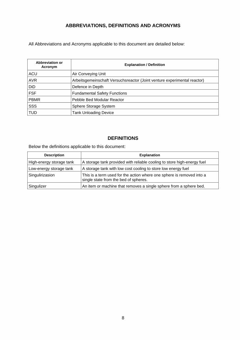
ABBREVIATIONS, DEFINITIONS AND ACRONYMS
All Abbreviations and Acronyms applicable to this document are detailed below:
Abbreviation or Acronym
Explanation / Definition
ACU Air Conveying Unit
AVR Arbeitsgemeinschaft Versuchsreactor (Joint venture experimental reactor)
DiD Defence in Depth
FSF Fundamental Safety Functions
PBMR Pebble Bed Modular Reactor
SSS Sphere Storage System
TUD Tank Unloading Device
DEFINITIONS
Below the definitions applicable to this document:
Description Explanation
High-energy storage tank A storage tank provided with reliable cooling to store high-energy fuel
Low-energy storage tank A storage tank with low cost cooling to store low energy fuel
Singulirizasion This is a term used for the action where one sphere is removed into a single state from the bed of spheres.
Singulizer An item or machine that removes a single sphere from a sphere bed.

9
LIST OF SYMBOLS
Symbol Explanation Unit
αD Acceleration of head rad/s2
C Spring index -
D Spring nominal diameter m
d Spring wire diameter m
Dosp Head outer diameter m
Dsp Sphere exit diameter (on the head where the spheres passes through) m
Dsh Head shaft diameter m
Fµ Force due to friction Nm
Jsh Momentum of shaft inertia m2 kg
Jsp Momentum of head inertia m2 kg
Jt Total moment of inertia of head and shaft m2 kg
Lpl Plate spring total length m
Lt Plate spring effective length (where spring action takes place) m
msp Head mass kg
msh Head shaft mass kg
pμ Pressure on head from the spheres as result of sphere mass on the head in friction calculations
Pa
r Radius of head used in integration calculation m
θD Angle of head acceleration ° (deg)
Sse Maximum endurance limit in shear for the spring MPa
Ssy Torsional yield strength on coil spring MPa
TD Torque required to accelerate head Nm
Tμ Torque required to overcome friction Nm
τa Stress amplitude of spring MPa
τmax Mean stress on spring MPa
ω0 Beginning velocity of head rad/s
ωsp Running velocity of head rad/s
W Weight of object N
y Distance from plate spring top, this distance equals the coil spring radius m

10
1. INTRODUCTION
1.1 BACKGROUND
The Tank Unloading Device (TUD) is a machine in the Sphere Storage System (SSS) of the
Pebble Bed Modular Reactor (PBMR) with the function of unloading spheres from a storage
vessel. The SSS interfaces with the fuel handling system, which is responsible for re-circulation
of fuel through the reactor, [1]. The fuel is in the form of graphite spheres with a diameter of
approximately 60 mm, [1] and [2].
Fuel circulation is required for burn-up measurement of the fuel. When the fuel is burned up,
the fuel handling system removes the fuel from the reactor to the sphere storage system and
replaces it with fresh fuel from the fresh fuel storage tank, [1]. The fuel is transported through a
pipeline by means of a combination of gravity and pneumatic forces where helium is used as
the transportation medium.
Burned-up fuel that is removed from the reactor is moved to the high energy storage section of
the sphere storage system. It is cooled there till the heat energy is low enough to move the fuel
over to the low energy storage part of the sphere storage system.
When the reactor is unloaded for maintenance, the partially burned-up or used fuel is unloaded
to the high energy section of the sphere storage system for storage. Graphite spheres are then
unloaded from the graphite tank into the reactor. After the maintenance is completed the fuel
spheres are returned from the SSS to the fuel handling system for refuelling of the reactor. The
refuelling process is to be done within a sphere circulation rate of approximately 242 spheres
per hour (normal operation), [1].
At the end of the plant life of 40 years, the spent fuel is stored for another 40 years before final
unloading will take place, moving the spent fuel to a waste handling facility, [1]. This unloading
will also be done by the fuel unloading machine.
Redistribution of fuel within the SSS is done in a nitrogen environment. Spent fuel is
transported from a high energy storage tank to the low energy storage tank after the fuel has
cooled down.
The fuel spheres that have to be removed from the storage tanks must be individually loaded
into the sphere pipe for transportation in a gas stream of helium or nitrogen to the required
destination. Before the spheres are loaded into the sphere pipelines, the broken spheres must
be separated from the usable spheres because broken spheres can block sphere transportation
pipelines.
The fuel handling system is a controlled system and operated sophisticatedly to ensure
accurate measurements of fuel and optimum fuel handling, [1]. Pipe routings and blowers are
11
sized for reactor performance and the sphere loading to the reactor must be correctly timed to
maintain optimum reactor performance with regard to fuel balance, [2].
The fuel handling system is one of the key systems of the pebble bed reactor. The components
of the fuel handling system are subjected to the helium atmosphere and high radiation.
Therefore components must ensure high reliability and must be maintainable, [8]. Experience
gained on the AVR (first German high temperature reactor) indicated that the fuel handling
components must become simpler, safer and easier to maintain, [8].
The SSS concept is a new system and at the development phase lags behind the other
systems. The previous SSS concept was cancelled due to nuclear safety requirements and it is
now required to enhance the new SSS concept to align with the basic design status of the fuel
handling system. The success of the current concept design for the whole spent fuel storage
system is dependent on the successful development of a tank unloading device which is a main
component of the SSS.
1.2 GOAL OF STUDY
The primary goal of this study is to develop a tank unloading device for nuclear spheres that will
comply with all the design requirements. To reach this goal within the available time frame, the
first step would be to upgrade the current unloading concept which has a risk of damaging fuel
spheres. This might be achieved by developing and fitting an impact limiting device to protect
the spheres against damage during impact.
If the implementation of the impact limiting device is not successful, another unloading machine
concept must be developed, but it must make use of work that has already been done on the
present concept.
1.3 SCOPE OF STUDY
The scope of this study is to develop an unloading machine within a helium environment, with
available and proven helium technology concepts. This is required to limit expensive
development tests in helium for the unloading machine and to save development and testing
time. This study will make use of proven helium technology concepts to develop the unloading
machine.
Furthermore the study must demonstrate that the developed machine will be reliable and safely
maintainable. Equipment failure must be identified to prevent damage to nuclear fuel.
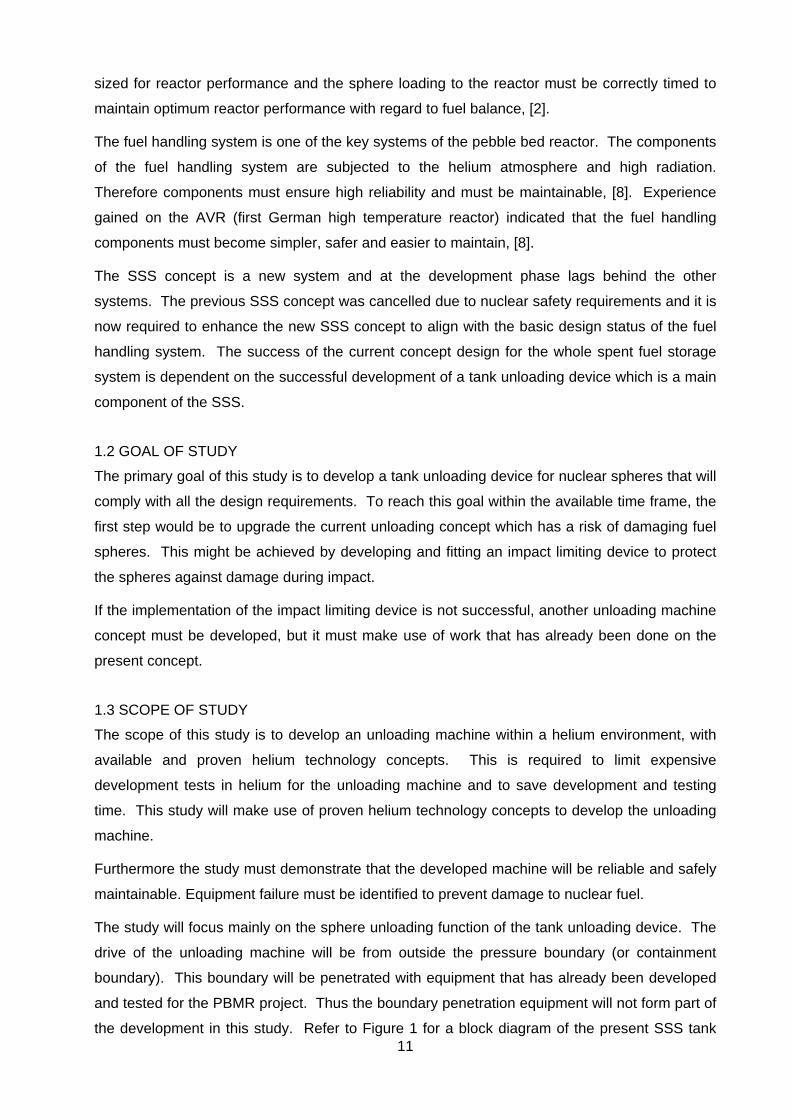
The study will focus mainly on the sphere unloading function of the tank unloading device. The
drive of the unloading machine will be from outside the pressure boundary (or containment
boundary). This boundary will be penetrated with equipment that has already been developed
and tested for the PBMR project. Thus the boundary penetration equipment will not form part of
the development in this study. Refer to Figure 1 for a block diagram of the present SSS tank
12
layout and the main components of the tank unloading device arranged in the allocated spaces.
The components and geometry which form part of the scope of the study are encircled with a
dotted line. It is important to note that the pressure boundary of the tank is positioned in such a
manner that when the pressure boundary is opened, it is opened into the controlled area of the
building.
Figure 1: Tank unloading device block diagram
The scope of the study
is encircled with a the
dotted line Head of the TUD
Drive shaft of the TUD
Maintenance pipe
for the TUD head
(400 mm diameter)
Pressure boundary
penetration
Storage tank
Drive actuator for the
TUD head
Sphere flow guide
13
2. LITERATURE SURVEY
2.1 INTRODUCTION
The literature study was performed to understand the environment where the tank unloading
device will be operational. The environment is a critical factor when materials are selected.
Furthermore, nuclear safety requirements were researched to ascertain what safety
requirements will be placed on the design. Other sphere loading and unloading concepts were
investigated for possible application in the present study.
2.2 HELIUM TECHNOLOGY
Helium technology is a term used in high-temperature gas reactors, [4]. This type of reactor
uses helium gas as a cooling medium, as opposed to water that is used in most other reactors.
Due to this new technology physicists are organising regular international meetings that are
held on the topic of High-Temperature Reactor Technology. At these meetings papers are
presented on helium technology and new findings are discussed. Some of these findings are
discussed in the following paragraphs.
Sliding connections, e.g. bearings and slides, are subjected to excessive wear due to the
atmospheric and thermal conditions created by the dry helium, even more so when the helium
temperature increases, [14]. “Hochtemperatur Reaktorbau GmbH, Mannheim, Federal Republic
of Germany”, did a study where ceramic coatings were applied to protect components in the
helium environment against frictional wear and diffusion welding. However, these new
technologies do not have an established track record, even though thoroughly tested.
Graphite becomes abrasive when it is operated in a helium environment, especially at high
temperatures [4]. Due to the graphite-coated fuel pebble, which is transported in helium
through the fuel handling pipe system, fine graphite dust will form, [5]. Most of this dust will
however be captured in the filter system.
Due to the small molecular size of helium it is difficult to prevent helium leakages, [4]. Therefore
penetrations through the helium pressure boundary should be limited. Usually drives are placed
outside the pressure boundary for maintenance purposes, requiring the remainder of the
mechanisms inside the pressure boundary to be reliable and resistant to cold welding in helium.
In France a research programme was conducted to investigate the feasibility of helium
technology, [4]. Results indicated that mechanisms in high temperature gas cooled reactors
need wear protection. The nuclear regulatory agencies will require tests in helium to determine
the durability of coatings on materials.
The friction coefficient between graphite and graphite, as well as between graphite and steel, is
higher in helium than in atmospheric air. It has been determined by studies performed, as
supported by the Department of Energy, [5], that the friction coefficient increases as the
14
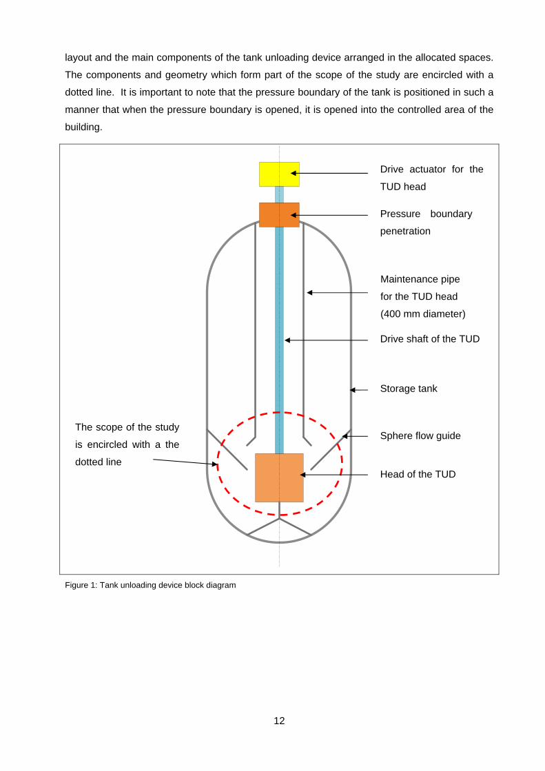
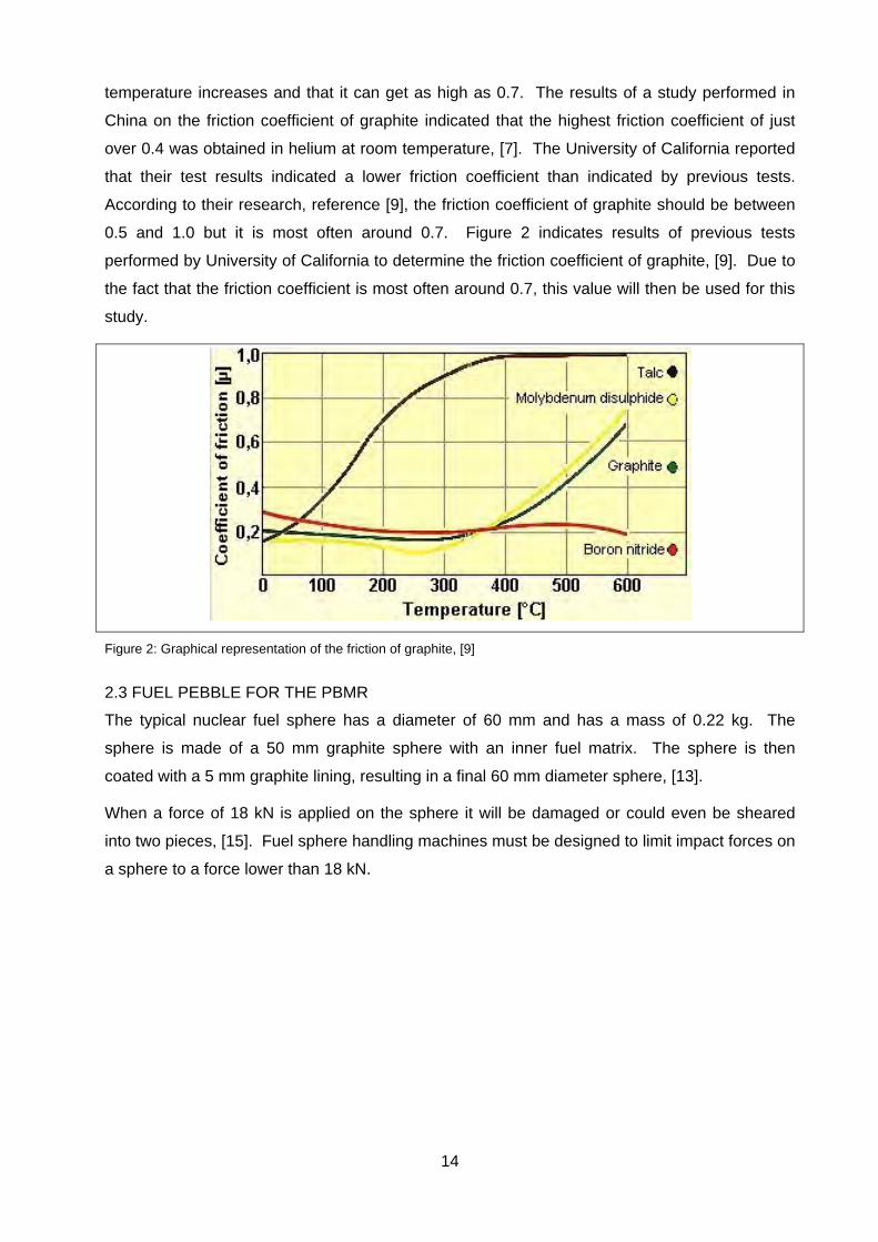
temperature increases and that it can get as high as 0.7. The results of a study performed in
China on the friction coefficient of graphite indicated that the highest friction coefficient of just
over 0.4 was obtained in helium at room temperature, [7]. The University of California reported
that their test results indicated a lower friction coefficient than indicated by previous tests.
According to their research, reference [9], the friction coefficient of graphite should be between
0.5 and 1.0 but it is most often around 0.7. Figure 2 indicates results of previous tests
performed by University of California to determine the friction coefficient of graphite, [9]. Due to
the fact that the friction coefficient is most often around 0.7, this value will then be used for this
study.
Figure 2: Graphical representation of the friction of graphite, [9]
2.3 FUEL PEBBLE FOR THE PBMR
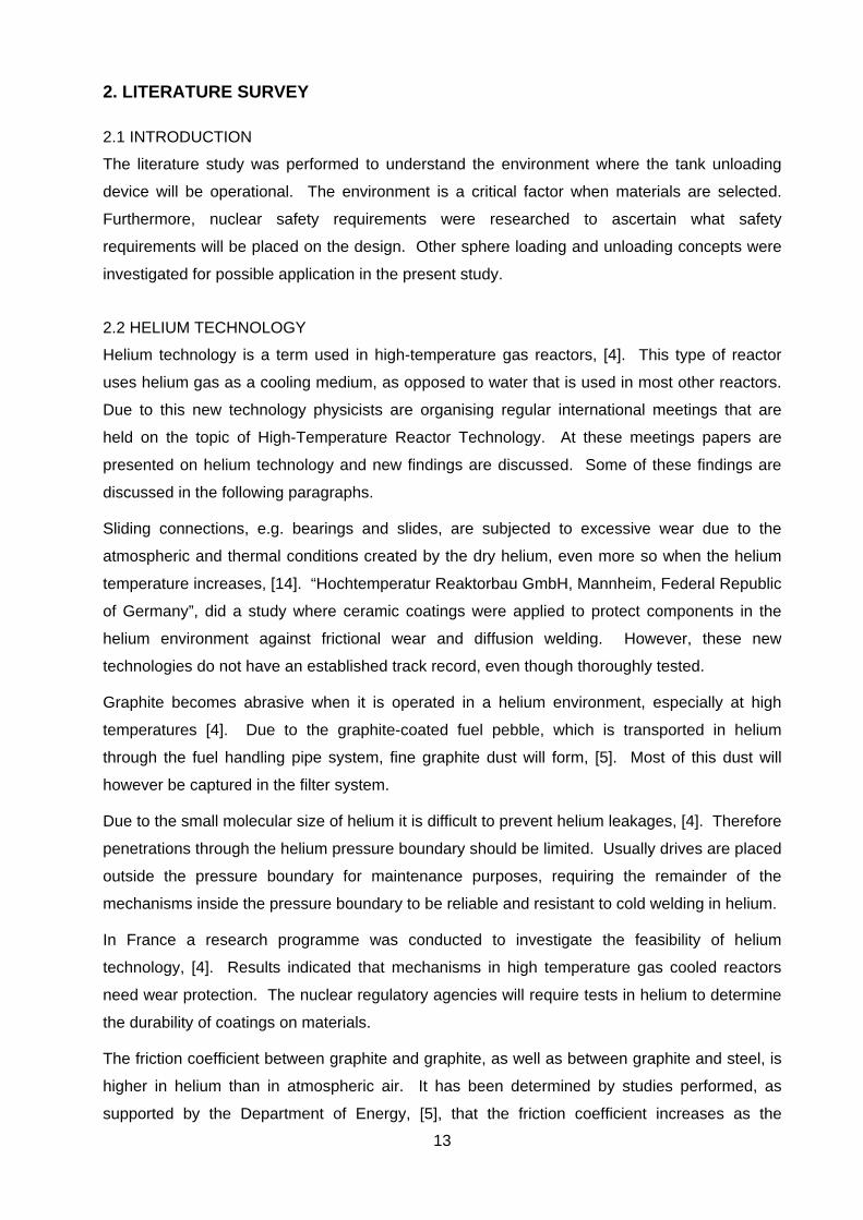
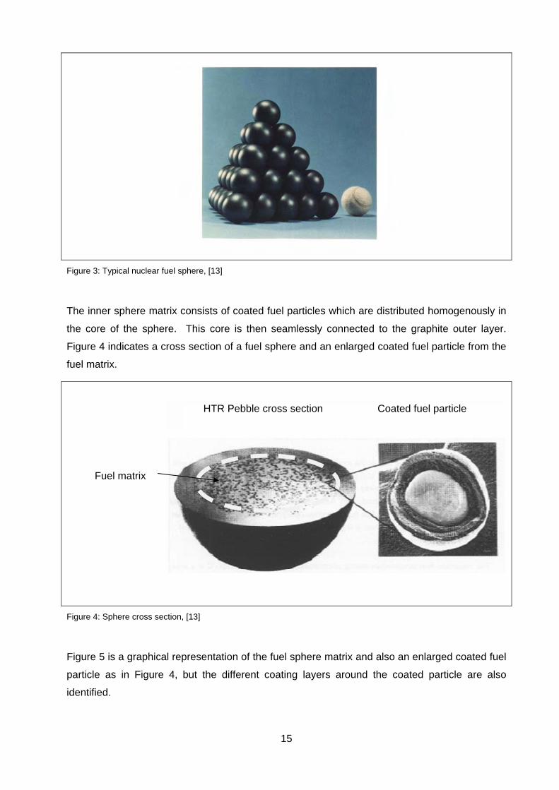
The typical nuclear fuel sphere has a diameter of 60 mm and has a mass of 0.22 kg. The
sphere is made of a 50 mm graphite sphere with an inner fuel matrix. The sphere is then
coated with a 5 mm graphite lining, resulting in a final 60 mm diameter sphere, [13].
When a force of 18 kN is applied on the sphere it will be damaged or could even be sheared
into two pieces, [15]. Fuel sphere handling machines must be designed to limit impact forces on
a sphere to a force lower than 18 kN.
15
Figure 3: Typical nuclear fuel sphere, [13]
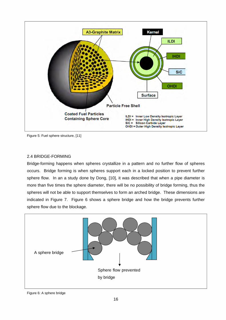
The inner sphere matrix consists of coated fuel particles which are distributed homogenously in
the core of the sphere. This core is then seamlessly connected to the graphite outer layer.
Figure 4 indicates a cross section of a fuel sphere and an enlarged coated fuel particle from the
fuel matrix.
Figure 4: Sphere cross section, [13]
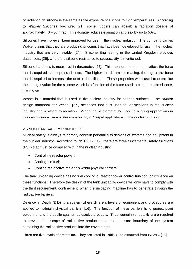
Figure 5 is a graphical representation of the fuel sphere matrix and also an enlarged coated fuel
particle as in Figure 4, but the different coating layers around the coated particle are also
identified.
HTR Pebble cross section Coated fuel particle
Fuel matrix
16
Figure 5: Fuel sphere structure, [11]
2.4 BRIDGE-FORMING
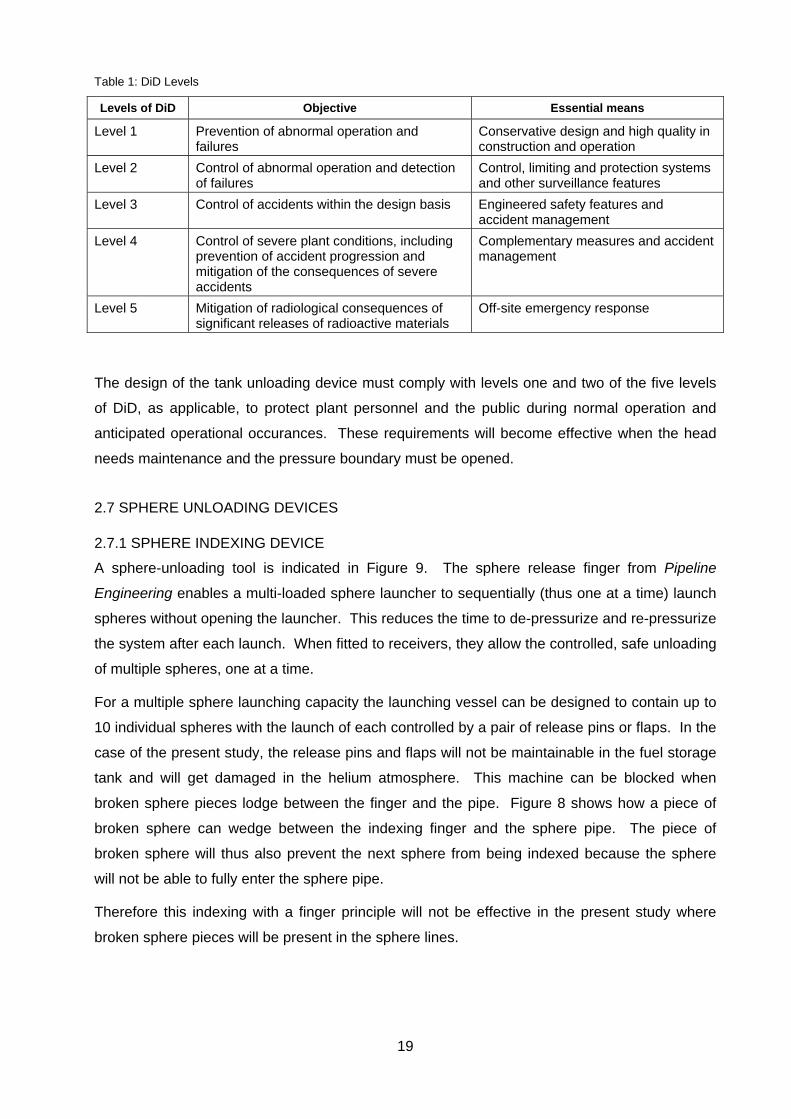
Bridge-forming happens when spheres crystallize in a pattern and no further flow of spheres
occurs. Bridge forming is when spheres support each in a locked position to prevent further
sphere flow. In an a study done by Dong, [10], it was described that when a pipe diameter is
more than five times the sphere diameter, there will be no possibility of bridge forming, thus the
spheres will not be able to support themselves to form an arched bridge. These dimensions are
indicated in Figure 7. Figure 6 shows a sphere bridge and how the bridge prevents further
sphere flow due to the blockage.
Figure 6: A sphere bridge
A sphere bridge
Sphere flow prevented
by bridge

17
Figure 7: Sketch of the core cavity and discharge pipe of the HTR-10, [8]
In the full scale test setup of the fuel handling system of the HTR-10 the diameter of the funnel
which transported the fuel was too small to prevent bridge forming. Therefore gas pulses were
used to break the bridge when a bridge was formed, [8].
2.5 SYNTHETIC MATERIALS IN THE NUCLEAR ENVIRONMENT
The application of materials in the PBMR environment is directly linked to helium technology.
As previously discussed, the materials will be introduced into a helium environment where they
will be subjected to a high-abrasive environment. Additionally materials in high-temperature gas
reactors will be subjected to helium temperatures of up to a 1000°C. However, the PBMR fuel
handling and storage system will be limited to a maximum temperature of 260 °C, [1].
Therefore the material specification on the tank unloading device allows more materials to be
used as in the reactor itself due to the lower temperatures. The abrasiveness of the helium
environment will also be lower due to the lower temperature, [4].
Silicone properties were researched to determine whether it could be used in the nuclear
industry for seals and springs. It was found that silicone is not resistant to radiation. The effect
500 mm pipe diameter
500 mm discharge pipe
Core cavity
18
of radiation on silicone is the same as the exposure of silicone to high temperatures. According
to Wacker Silicones brochure, [21], some rubbers can absorb a radiation dosage of
approximately 40 – 50 mrad. This dosage reduces elongation at break by up to 50%.
Silicones have however been improved for use in the nuclear industry. The company James
Walker claims that they are producing silicones that have been developed for use in the nuclear
industry that are very reliable, [24]. Silicone Engineering in the United Kingdom provides
datasheets, [25], where the silicone resistance to radioactivity is mentioned.
Silicone hardness is measured in durameter, [26]. This measurement unit describes the force
that is required to compress silicone. The higher the durameter reading, the higher the force
that is required to increase the dent in the silicone. These properties were used to determine
the spring k-value for the silicone which is a function of the force used to compress the silicone,
F = k × Δx.
Vespel is a material that is used in the nuclear industry for bearing surfaces. The Dupont
design handbook for Vespel, [27], describes that it is used for applications in the nuclear
industry and resistant to radiation. Vespel could therefore be used in bearing applications in
this design since there is already a history of Vespel applications in the nuclear industry.
2.6 NUCLEAR SAFETY PRINCIPLES
Nuclear safety is always of primary concern pertaining to designs of systems and equipment in
the nuclear industry. According to INSAG 12, [12], there are three fundamental safety functions
(FSF) that must be complied with in the nuclear industry:
Controlling reactor power;
Cooling the fuel;
Confine radioactive materials within physical barriers.
The tank unloading device has no fuel cooling or reactor power control function, or influence on
these functions. Therefore the design of the tank unloading device will only have to comply with
the third requirement, confinement, when the unloading machine has to penetrate through the
radioactive barriers.
Defence in Depth (DiD) is a system where different levels of equipment and procedures are
applied to maintain physical barriers, [16]. The function of these barriers is to protect plant
personnel and the public against radioactive products. Thus, containment barriers are required
to prevent the escape of radioactive products from the pressure boundary of the system
containing the radioactive products into the environment.
There are five levels of protection. They are listed in Table 1, as extracted from INSAG, [16]:
19
Table 1: DiD Levels
Levels of DiD Objective Essential means
Level 1 Prevention of abnormal operation and failures
Conservative design and high quality in construction and operation
Level 2 Control of abnormal operation and detection of failures
Control, limiting and protection systems and other surveillance features
Level 3 Control of accidents within the design basis Engineered safety features and accident management
Level 4 Control of severe plant conditions, including prevention of accident progression and mitigation of the consequences of severe accidents
Complementary measures and accident management
Level 5 Mitigation of radiological consequences of significant releases of radioactive materials
Off-site emergency response
The design of the tank unloading device must comply with levels one and two of the five levels
of DiD, as applicable, to protect plant personnel and the public during normal operation and
anticipated operational occurances. These requirements will become effective when the head
needs maintenance and the pressure boundary must be opened.
2.7 SPHERE UNLOADING DEVICES
2.7.1 SPHERE INDEXING DEVICE
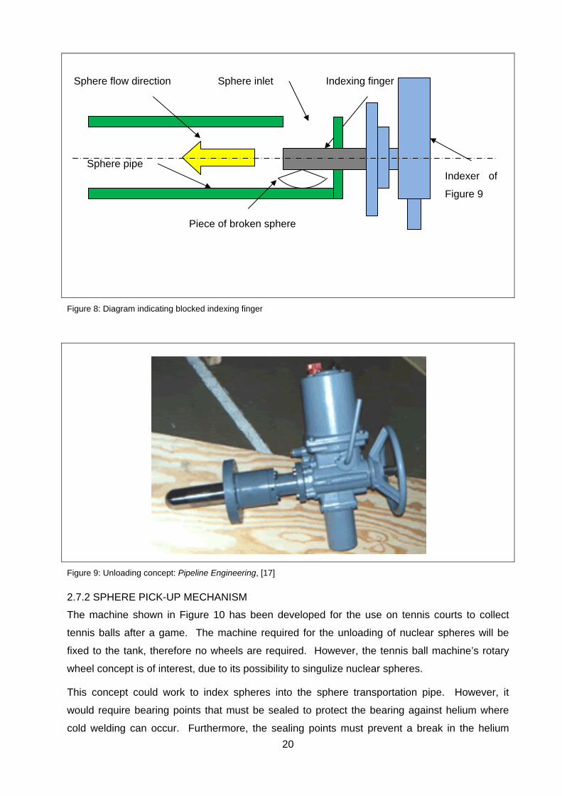
A sphere-unloading tool is indicated in Figure 9. The sphere release finger from Pipeline
Engineering enables a multi-loaded sphere launcher to sequentially (thus one at a time) launch
spheres without opening the launcher. This reduces the time to de-pressurize and re-pressurize
the system after each launch. When fitted to receivers, they allow the controlled, safe unloading
of multiple spheres, one at a time.
For a multiple sphere launching capacity the launching vessel can be designed to contain up to
10 individual spheres with the launch of each controlled by a pair of release pins or flaps. In the
case of the present study, the release pins and flaps will not be maintainable in the fuel storage
tank and will get damaged in the helium atmosphere. This machine can be blocked when
broken sphere pieces lodge between the finger and the pipe. Figure 8 shows how a piece of
broken sphere can wedge between the indexing finger and the sphere pipe. The piece of
broken sphere will thus also prevent the next sphere from being indexed because the sphere
will not be able to fully enter the sphere pipe.
Therefore this indexing with a finger principle will not be effective in the present study where
broken sphere pieces will be present in the sphere lines.
20
Figure 8: Diagram indicating blocked indexing finger
Figure 9: Unloading concept: Pipeline Engineering, [17]
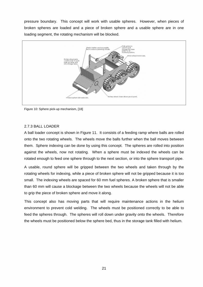
2.7.2 SPHERE PICK-UP MECHANISM
The machine shown in Figure 10 has been developed for the use on tennis courts to collect
tennis balls after a game. The machine required for the unloading of nuclear spheres will be
fixed to the tank, therefore no wheels are required. However, the tennis ball machine’s rotary
wheel concept is of interest, due to its possibility to singulize nuclear spheres.
This concept could work to index spheres into the sphere transportation pipe. However, it
would require bearing points that must be sealed to protect the bearing against helium where
cold welding can occur. Furthermore, the sealing points must prevent a break in the helium
Sphere pipe
Piece of broken sphere
Indexing finger Sphere inlet Sphere flow direction
Indexer of
Figure 9
21
pressure boundary. This concept will work with usable spheres. However, when pieces of
broken spheres are loaded and a piece of broken sphere and a usable sphere are in one
loading segment, the rotating mechanism will be blocked.
Figure 10: Sphere pick-up mechanism, [18]
2.7.3 BALL LOADER
A ball loader concept is shown in Figure 11. It consists of a feeding ramp where balls are rolled
onto the two rotating wheels. The wheels move the balls further when the ball moves between
them. Sphere indexing can be done by using this concept. The spheres are rolled into position
against the wheels, now not rotating. When a sphere must be indexed the wheels can be
rotated enough to feed one sphere through to the next section, or into the sphere transport pipe.
A usable, round sphere will be gripped between the two wheels and taken through by the
rotating wheels for indexing, while a piece of broken sphere will not be gripped because it is too
small. The indexing wheels are spaced for 60 mm fuel spheres. A broken sphere that is smaller
than 60 mm will cause a blockage between the two wheels because the wheels will not be able
to grip the piece of broken sphere and move it along.
This concept also has moving parts that will require maintenance actions in the helium
environment to prevent cold welding. The wheels must be positioned correctly to be able to
feed the spheres through. The spheres will roll down under gravity onto the wheels. Therefore
the wheels must be positioned below the sphere bed, thus in the storage tank filled with helium.
22
Figure 11: Ball Loader
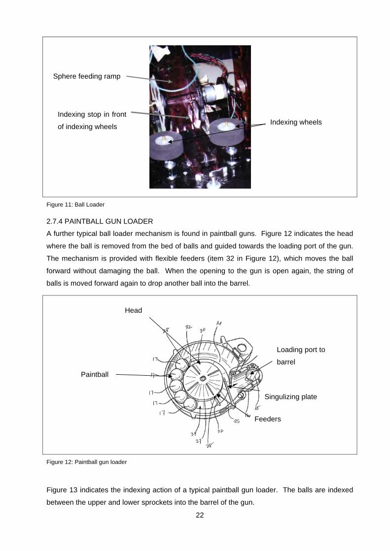
2.7.4 PAINTBALL GUN LOADER
A further typical ball loader mechanism is found in paintball guns. Figure 12 indicates the head
where the ball is removed from the bed of balls and guided towards the loading port of the gun.
The mechanism is provided with flexible feeders (item 32 in Figure 12), which moves the ball
forward without damaging the ball. When the opening to the gun is open again, the string of
balls is moved forward again to drop another ball into the barrel.
Figure 12: Paintball gun loader
Figure 13 indicates the indexing action of a typical paintball gun loader. The balls are indexed
between the upper and lower sprockets into the barrel of the gun.
Indexing wheels
Sphere feeding ramp
Indexing stop in front
of indexing wheels
Loading port to
barrel
Paintball
Head
Singulizing plate
Feeders

23
Figure 13: Paintball gun singulizer, [19]
These loaders are reliable in loading balls due to the good quality of the balls. The balls are
standard in size and no broken balls are present. When broken balls are introduced into the
mechanism, blockages will occur causing no feed to the gun because these mechanisms are
not designed to operate with broken paintballs.
2.7.5 LEVITATION STIR BALL LOADER
Figure 15 is a machine that is used to load plenums with balls. Figure 16(b) indicates these
plenums. Figure 16(a) indicates the main components of the loader section. The plenum (item
21 in Figure 16) is filled with spheres by the rake, item 10 in Figure 16(a), which is moved
linearly by a pneumatically operated piston. When the plenum is full it is taken out and replaced
with an empty plenum.
This concept will not be successful for the present study application. This design works only
with usable spheres. When pieces of broken spheres are present, a sphere location hole can
be filled with a piece of broken sphere and a usable sphere, causing the plenum to be stuck
because the sphere is protruding from the plenum into the section above the plenum. Figure 14
shows how a piece of sphere will block this machine.

24
Figure 14: Diagram showing blocked movement
Figure 15: Levitation stir ball loader, [20]
Item 21 of Figure 16
Piece of a sphere and a
sphere in one position
Movement of lower part blocked due to piece of broken sphere

25
Figure 16: Main components and loading plenum, [20]
2.7.6 NUCLEAR FUEL SPHERE UNLOADING DEVICES
There are other fuel unloading device concepts from earlier concept designs of pebble bed
reactors. Figure 17 shows some conceptual drawings of unloading devices that were done in
1962 for a conceptual pebble bed design, [21].
These designs are all unloading fuel through the bottom of the tank, while it is required for the
present study to unload fuel only through the top of the storage tank. These concepts will be
investigated further during the research study.
Figure 17: Gravity fuel unloading devices, [21]
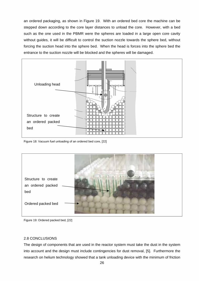
Figure 18 shows an unloading machine concept for the unloading of an ordered bed core, [22].
This unloading machine is a vacuum concept opposed to the gravity concept as indicated in
Figure 17. An ordered bed core is when the spheres are packed in the core in guides to create
(a) (b)
26
an ordered packaging, as shown in Figure 19. With an ordered bed core the machine can be
stepped down according to the core layer distances to unload the core. However, with a bed
such as the one used in the PBMR were the spheres are loaded in a large open core cavity
without guides, it will be difficult to control the suction nozzle towards the sphere bed, without
forcing the suction head into the sphere bed. When the head is forces into the sphere bed the
entrance to the suction nozzle will be blocked and the spheres will be damaged.
Figure 18: Vacuum fuel unloading of an ordered bed core, [22]
Figure 19: Ordered packed bed, [22]
2.8 CONCLUSIONS
The design of components that are used in the reactor system must take the dust in the system
into account and the design must include contingencies for dust removal, [5]. Furthermore the
research on helium technology showed that a tank unloading device with the minimum of friction
Ordered packed bed
Structure to create
an ordered packed
bed
Structure to create
an ordered packed
bed
Unloading head

27
components must be designed or selected. The components subjected to friction must be
designed to withstand the highly frictional environment of dust and helium.
It can also be concluded that a safe design, from a maintenance point of view, will be
constructed from metallic items rather than silicone type of materials because metallic items are
more resistant to radioactivity.
The maintenance requirements of the tank unloading device must take in consideration that the
tank unloading device will be in a radioactive environment. Based on the research regarding
nuclear safety principles, care must be taken when opening a radioactive containment system
or area.
The sphere handling concepts that were researched and described will not succeed in its
present designed layout as a tank unloading device. All these concepts have too many friction
points that can fail due to wear of the bearing interfaces. To prevent failure of these
components due to wear, regular maintenance actions will be required during the TUD’s
lifetime. These unloading concepts have not been designed for easy and safe maintenance in
the radioactive environment.
28
3. CONCEPTUAL DESIGN
3.1 INTRODUCTION
This section presents the concepts that were developed for the tank unloading device. A short
description will be given of the concepts. Thereafter a concept selection will be done and then
future development will be pointed out.
3.2 DESIGN REQUIREMENTS AND DESIGN SPECIFICATIONS
The following functional requirements are directly applicable to the TUD and summarised as
follows:
Unloading performance: amount of spheres per hour;
Operating medium: helium and nitrogen;
Maintenance: time required for maintenance in radioactive environment;
Broken pieces separation: description of identification of broken pieces to follow.
The main performance specification that the tank unloading machine must comply with is:
Deliver a minimum of 333 spheres/hour;
Indexing must be at regular intervals.
Safety and maintenance requirements are generally applicable to equipment in the nuclear
industry. Safety requirements must be adhered to in the nuclear industry. The drive of the tank
unloading device will penetrate through the pressure boundary into the radioactive environment,
requiring that this concept must be designed to be functional in the radioactive environment
filled with dust and helium. A robust and maintainable tank unloading device must be designed.
Maintenance procedures must be developed for each maintenance task in the nuclear industry
to ensure personnel safety due to the high risk of radiation. Therefore equipment is designed
for low maintenance requirements to reduce cost on elaborative maintenance preparation and
tasks.
3.3 CONCEPT GENERATION
Two concepts are being investigated for this study. Both these concepts utilize an unloading
head in the storage tank with a drive unit outside the storage tank with a penetration item to
penetrate safely through the containment barrier into the tank where radioactive fuel is stored.
The penetration item will not be part of the study because it has already been tested for
reliability in the nuclear industry.
The first concept utilizes pneumatic suction to lift the sphere into the sphere transportation pipe,
while the second concept uses gravity and mechanical equipment to unload the spheres from
the storage tank.

29
To remove spheres from a storage tank into a transportation pipe, the spheres must be
loosened from the interlocking force caused by the weight of the spheres on top of them. Then
the spheres must be aligned for indexed removal, where after they can be released in a
separately into the transportation pipe.
It was decided to build concept-demonstrating models. The purpose of these models was to
demonstrate the concept of suction or gravity removal. The one model used suction to remove
spheres, while the other concept used rotational movement to remove the spheres. Figure 20
shows the suction model and Figure 21 the gravity model that were built.
Both concepts were functional in unloading the spheres. However, the suction option required a
high suction rate to lift the sphere and suck it into the lifting pipe. Once the sphere was in the
suction pipe the sphere accelerated to a very high velocity due to the high suction rate required
to lift the sphere from its resting position. Therefore the suction concept was not developed any
further.
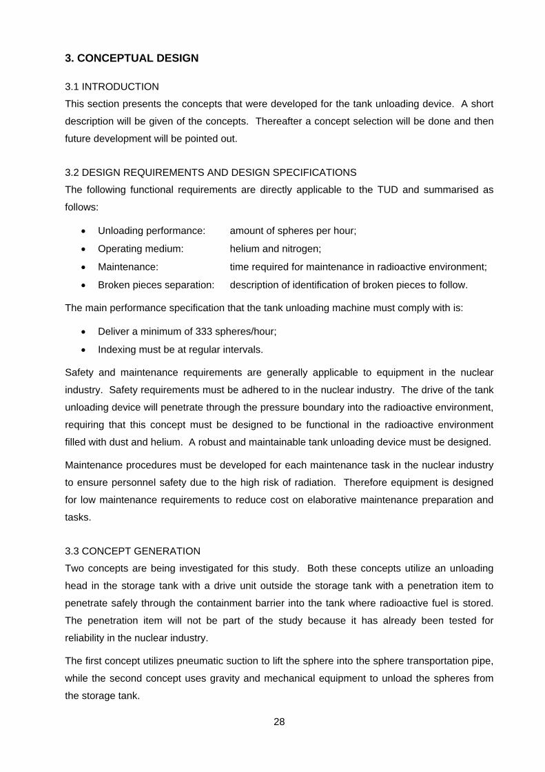
3.3.1 CONCEPT 1: PNEUMATIC SUCTION
This concept uses pneumatic suction to lift the fuel sphere from its position into the suction
nozzle of the head into the suction pipe in the unloading head. Figure 20(a) is a picture of the
scale model that was built to do the suction tests. Figure 20(b) is a cross section of the head
with the conveying pipe inside, the bottom of the tank and some spheres.
The spheres in the tank roll down to the lowest point in the tank. There is a base fixed in the
middle of the tank bottom where the head tank unloading device interfaces for rotational bearing
support. The space between the head and the tank bottom is approximately 65 mm to allow a
ring of spheres to form around the base underneath the head. The head of the unloading
device rotates just above the spheres while enough air to lift a sphere is sucked into the suction
nozzle of the head. When the suction nozzle in the head is moved over a sphere the sphere is
sucked into the suction nozzle of the head, from where the sphere is transported the top.
Meanwhile the head rotates further to the next sphere lying against the base which is then
sucked in. Singulising of spheres are achieved when the head rotates and spheres lying in a
ring around the base are sucked in as the nozzle pass over them. The unloading intervals
between the spheres can be adjusted by rotating the head faster for shorter intervals, or slower
for longer intervals.
This concept was able to unload spheres. Furthermore, the delivery of spheres can be reduced
by decreasing the head rotational speed, with zero delivery at zero speed. Thus with better
control of the blower performance and the rotational speed of the head it should be possible to
deliver the required 333 spheres/hour. Due to the limited selection of spheres and blowers
available these tests were performed with lighter sphere masses and a blower capacity that is to
30
powerful. However, the purpose of the test was not to verify the design, but only to confirm that
suction could be used as an unloading possibility.
Figure 20: Vacuum concept (a) test model; (b) the detail of the unloading head
A disadvantage of this concept is that high sphere velocities are created. When a sphere is
lying in the open, thus not in a pipe, a high gas velocity is required from a nozzle to lift the
sphere and suck the sphere into the nozzle. The gas velocity over the sphere causes friction
over the sphere to lift it. Once the sphere is lifted a pressure differential exists over the sphere
causing it to be lifted into the lower pressure region. Once the sphere enters the suction pipe it
is transported due to a pressure differential over the sphere due to the moving transportation
gas. To create this pressure differential over the sphere less gas flow velocity is required as
when a sphere is to be lifted from a flat area. A further disadvantage of the high suction velocity
is that it is now possible to lift more spheres into the suction pipe due to this high gas velocity.
When there is too much spheres in the vertical sphere transport pipe the spheres will hover in
midair due to blower capacity that cannot lift the spheres further. The string of spheres will then
hover in the suction pipe until the suction is removed and the spheres are allowed to roll down.
To make this concept more acceptable it would be required to decrease the gas velocity once
the sphere enters the conveying nozzle in the head, and then to increase it again when the
sphere is at the top of the tank so that the next sphere can be sucked into the conveying pipe.
The gas velocity can be controlled with by-pass pipes between the suction nozzle and the top
exit. When a sphere is in the lifting section between the nozzle and the top exit, some of the
Critical geometric
dimensions
Suction / conveying
pipe
Single sphere to be lifted
(b) (a)
Sphere suction
nozzle
Head
Base for the bearing interface of
the head
Sphere transportation
pipe, for sphere lifting
to the tank top
31
gases will by-pass the sphere pipe in the parallel by-pass pipe. This by-pass pipe must be
smaller in diameter than the sphere pipe to maintain some gas-flow through the sphere pipe for
sphere lifting. There is however a possibility that the smaller diameter by-pass pipe can be
clogged with graphite dust.
It will be possible to do maintenance on the vacuum concept by removing the head with its
driveshaft at the top of the tank. This process will require opening of the pressure boundary
which will require special tools in the nuclear environment.
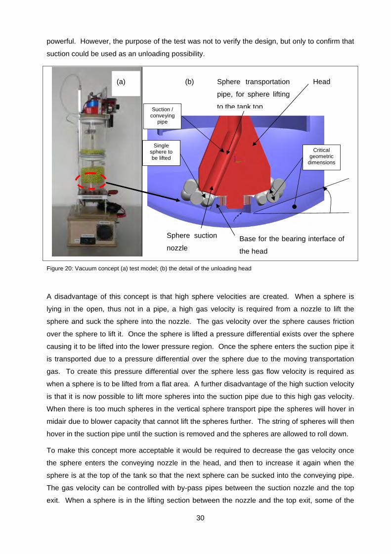
3.3.2 CONCEPT 2: GRAVITY UNLOADING
Figure 21(a) is a scale model that was built to test the gravity unloading concept. Concept 2
uses gravity to drop spheres down into a sphere transport line into a constant gas flow rate.
Figure 21(b) indicates a single sphere in the groove between the tank bottom and the head of
the tank unloading device. The groove has the width of a sphere and the purpose is to form a
single row or string of spheres in the groove.
Spheres are taken from the sphere bed into the groove. While the head of the unloading device
rotates a sphere rolls down through the head into the sphere pipe below. Spheres can be
indexed faster by rotating the head faster, and vice versa.
The length of the vertical pipe segment in the head can influence the amount of spheres
unloaded into the gas stream. The pipe fills up with spheres and the bottom sphere is taken by
the gas stream. A short pipe segment will prevent too many spheres from flowing into the gas
stream.
Figure 21: Combination of gravity concept
(b) (a) Sphere
transport
line
Gas supply
line
Sphere Head
Groove for
sphere flow
32
Spheres were unloaded in strings by the gravity concept. By decreasing the rotational speed
delivery had a tendency to decrease until zero spheres were delivered when the head was not
rotating. When there are too many spheres in the pipe the given blower does not have the
capacity to lift the mass of spheres. Again the purpose of this test was only to show that the
gravity unloading concept was possible.
It was concluded that better control had to be incorporated into the design for better
singulization of the spheres because the gravity concept worked well to unload spheres only
when the head rotated slowly. When the head was rotating too fast a string of spheres fell
through into the sphere transport pipe. It is therefore recommended that a more effective
singulizing action must be developed for this concept to increase timely indexing in the
unloading sequence.
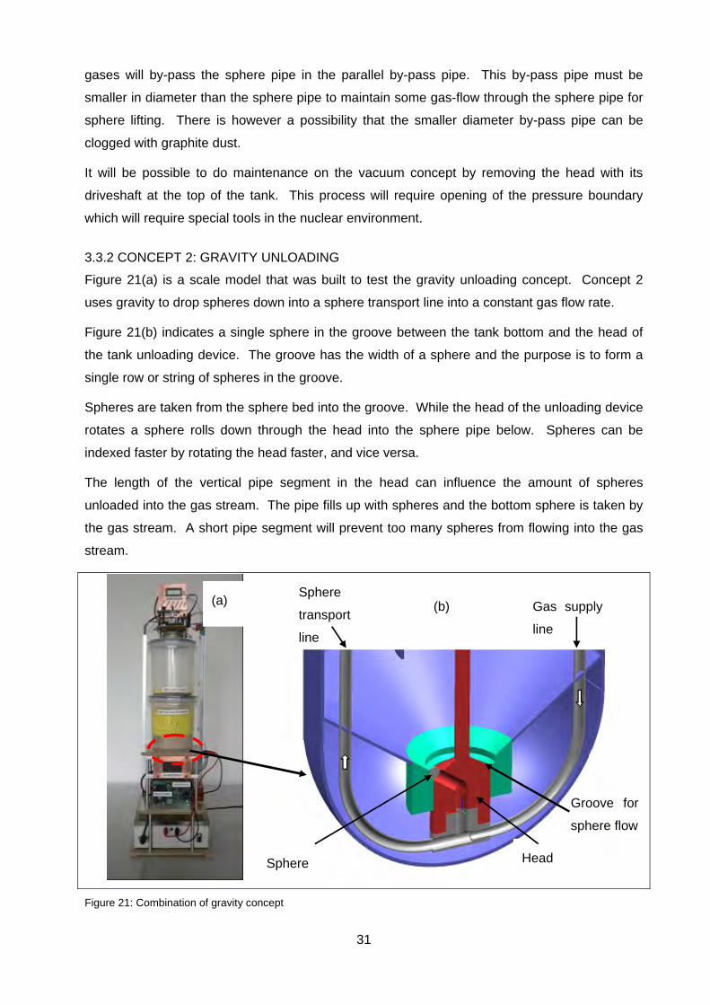
3.4 CONCEPT SELECTION
For the concept selection the criteria in Table 2 will be used. The weights scaling is indicated
with 1 as the most important weight.
Table 2: Concept selection criteria
Criteria Criteria weight
Description
Control of indexing 4 Indicate how accurate the indexing of spheres can be controlled.
1: no control
10: accurate control
Control of sphere speed 5 Is the sphere speed within transportation speed limits, with a maximum of 10 m/s?
1: speed not in limits
10: speed within limits
Sphere string forming 3 Is there a tendency to load strings of spheres into the sphere transport pipe?
1: yes
10: No strings
Dust environment 2 Are there changes that dust will cause failure of the concept?
1: yes
10: no
Helium environment 1 Are there frictional components other than vespel?
1: yes there are
10: no, nothing
Construction simplicity 7 Constructability of the concept 1: complex
10: easy
Maintenance 6 Is maintenance possible? 1: difficult
10: easy
Development status 8 Is further development required? 1: yes
10: no

33
Table 3: Concept selection
Criteria Vacuum Gravity Selection
Control of indexing 4/10 5/10 Gravity
Control of sphere speed 1/10 7/10 Gravity
Sphere string forming 8/10 8/10 Any
Dust environment 3/10 8/10 Gravity
Helium environment 8/10 8/10 Any
Construction simplicity 8/10 7/10 Vacuum
Maintenance possible 8/10 8/10 Any
Further development 3/10 5/10 Gravity
Totals 43 56
From Table 3 the gravity option seems to be the better option. Therefore the gravity option has
been selected. In both cases improvement is required for the concepts to comply with the
design requirements. There is documented evidence available from the gas reactor history on
gravity unloading which added to the choice of selecting the gravity concept for improvement.
These concepts were shortly described in the literature study.
This gravity concept has a slightly different geometry than those given in the literature study. It
was done because it was reasoned that the sphere will line up in the groove for single
unloading.
3.5 CONCLUSION
The principle of vacuum lifting and gravity unloading are both workable solutions. It is therefore
envisaged that both concepts can be further developed into working concepts. With the limited
time frame the gravity concept was selected because of better compliance with the
requirements.
It is however evident that the concept needs to be developed further to allow more reliable
indexing.
34
4. DETAIL DESIGN
4.1 INTRODUCTION
The gravity concept was selected, but with the recommendation of further development of the
indexing mechanism. The detail design will include the improvement of the concept as well as
the calculations to ensure that the tank unloading design will comply with the design
specifications.
4.2 DETAIL DESIGN
4.2.1 CONCEPT IMPROVEMENT
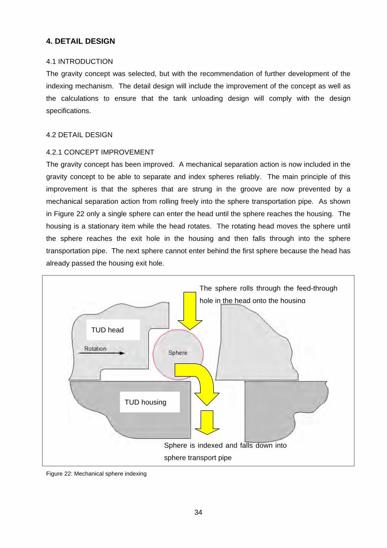
The gravity concept has been improved. A mechanical separation action is now included in the
gravity concept to be able to separate and index spheres reliably. The main principle of this
improvement is that the spheres that are strung in the groove are now prevented by a
mechanical separation action from rolling freely into the sphere transportation pipe. As shown
in Figure 22 only a single sphere can enter the head until the sphere reaches the housing. The
housing is a stationary item while the head rotates. The rotating head moves the sphere until
the sphere reaches the exit hole in the housing and then falls through into the sphere
transportation pipe. The next sphere cannot enter behind the first sphere because the head has
already passed the housing exit hole.
Figure 22: Mechanical sphere indexing
The sphere rolls through the feed-through
hole in the head onto the housing
Sphere is indexed and falls down into
sphere transport pipe
TUD housing
TUD head
35
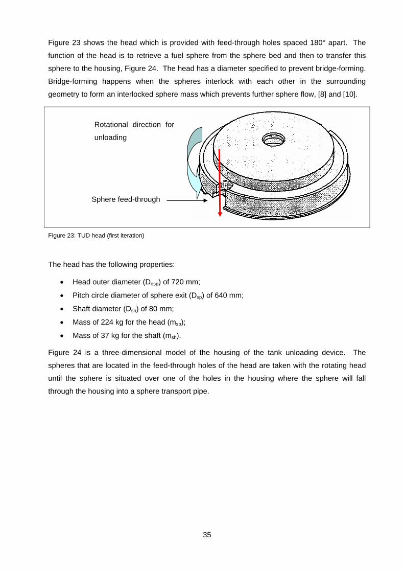
Figure 23 shows the head which is provided with feed-through holes spaced 180° apart. The
function of the head is to retrieve a fuel sphere from the sphere bed and then to transfer this
sphere to the housing, Figure 24. The head has a diameter specified to prevent bridge-forming.
Bridge-forming happens when the spheres interlock with each other in the surrounding
geometry to form an interlocked sphere mass which prevents further sphere flow, [8] and [10].
Figure 23: TUD head (first iteration)
The head has the following properties:
Head outer diameter (Dosp) of 720 mm;
Pitch circle diameter of sphere exit (Dsp) of 640 mm;
Shaft diameter (Dsh) of 80 mm;
Mass of 224 kg for the head (msp);
Mass of 37 kg for the shaft (msh).
Figure 24 is a three-dimensional model of the housing of the tank unloading device. The
spheres that are located in the feed-through holes of the head are taken with the rotating head
until the sphere is situated over one of the holes in the housing where the sphere will fall
through the housing into a sphere transport pipe.
Sphere feed-through
Rotational direction for
unloading

36
Figure 24: TUD housing
The disadvantage of this concept is that fuel spheres can be damaged due to spheres being
caught between the separating (or singulirizasion) mechanisms. Mechanical separation acting
in the form of a scissor is used to separate spheres and this scissor action will damage the fuel
spheres when a sphere is caught between the separating mechanisms.
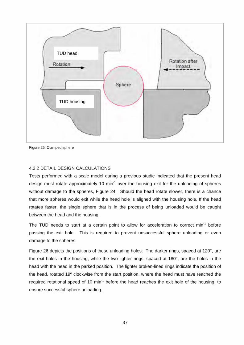
Striking of spheres in the scissor mechanism can occur when the head rotates too fast and the
sphere cannot pass through in time before the gap closes, or when the head rotates too slowly
and more than one sphere fall through, causing the last sphere to be clamped between the
head and the housing, as indicated in Figure 25. With broken spheres in the tank that will also
pass through the tank unloading device the risk of blockages increases.
The timing of the unloading machine is based on a sphere that must be delivered into the
sphere transportation pipe every 10.8 seconds. It is required to deliver a minimum of 333
spheres per hour which is one sphere every 10.8 seconds:
3600 s / 333 spheres per hour = 10.8 s (1)
The housing in Figure 24 shows three holes, where a sphere must be delivered every 10.8
seconds per hole. (During redistribution only one hole will be used and during reactor refilling
all three holes will be used. The required rotational speed is:
60 s·min-1 / 10.8 s = 5.6 min-1 (2)
The unloading device will be developed for a speed of 10 min-1 to be able to deliver more than
the required minimum of 333 spheres per hour. When fewer spheres are required the tank
unloading device can be operated in a stop-start operation to fill and maintain a sphere buffer in
the fuel handling system.
Through these holes the
spheres exits the tank
unloading device.
37
Figure 25: Clamped sphere
4.2.2 DETAIL DESIGN CALCULATIONS
Tests performed with a scale model during a previous studie indicated that the present head
design must rotate approximately 10 min-1 over the housing exit for the unloading of spheres
without damage to the spheres, Figure 24. Should the head rotate slower, there is a chance
that more spheres would exit while the head hole is aligned with the housing hole. If the head
rotates faster, the single sphere that is in the process of being unloaded would be caught
between the head and the housing.
The TUD needs to start at a certain point to allow for acceleration to correct min-1 before
passing the exit hole. This is required to prevent unsuccessful sphere unloading or even
damage to the spheres.
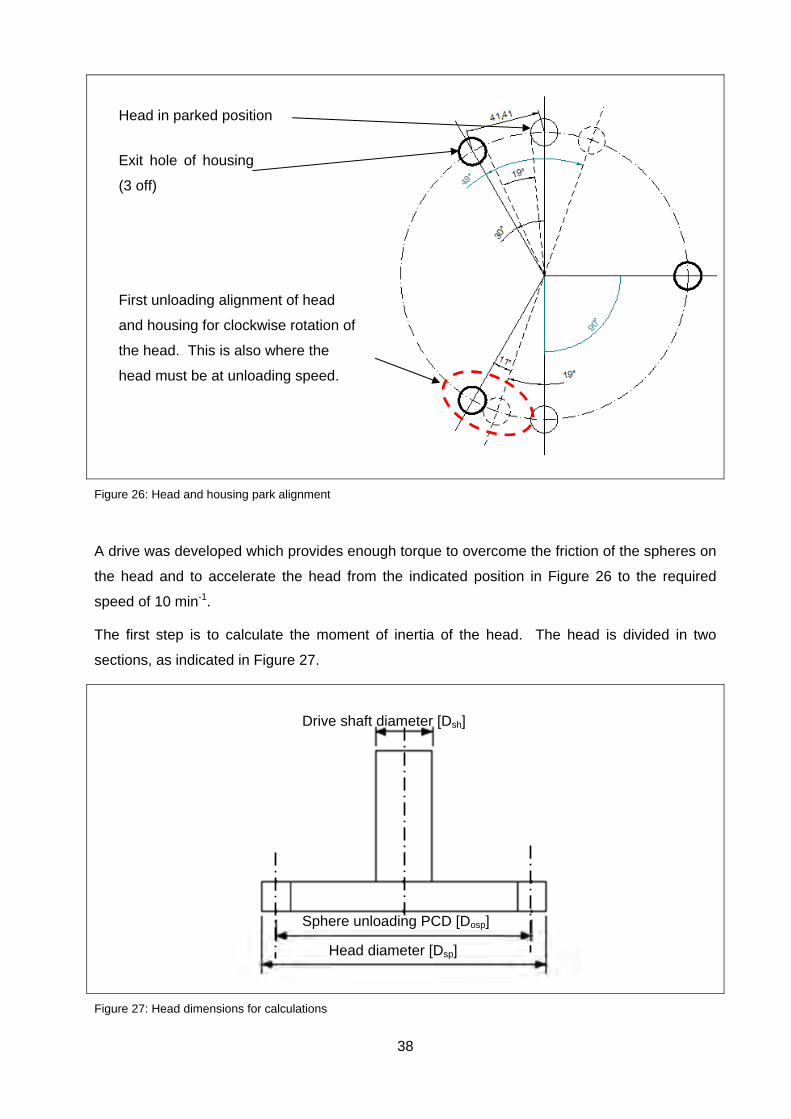
Figure 26 depicts the positions of these unloading holes. The darker rings, spaced at 120°, are
the exit holes in the housing, while the two lighter rings, spaced at 180°, are the holes in the
head with the head in the parked position. The lighter broken-lined rings indicate the position of
the head, rotated 19º clockwise from the start position, where the head must have reached the
required rotational speed of 10 min-1 before the head reaches the exit hole of the housing, to
ensure successful sphere unloading.
TUD head
TUD housing
38
Figure 26: Head and housing park alignment
A drive was developed which provides enough torque to overcome the friction of the spheres on
the head and to accelerate the head from the indicated position in Figure 26 to the required
speed of 10 min-1.
The first step is to calculate the moment of inertia of the head. The head is divided in two
sections, as indicated in Figure 27.
Figure 27: Head dimensions for calculations
Head in parked position
Exit hole of housing
(3 off)
First unloading alignment of head
and housing for clockwise rotation of
the head. This is also where the
head must be at unloading speed.
Head diameter [Dsp]
Sphere unloading PCD [Dosp]
Drive shaft diameter [Dsh]

39
The moment of inertia of the head is then calculated [28]:
The equation for the shaft [28]: Jsh = 0.5·msh·(Dsh/2)2 (3)
The equation for the head disk [28]: Jsp = 0.5·msp·(Dosp/2)2 (4)
With the head rotating at 10 min-1 (or 1.047 rad/s) the head has a total moment of inertia
(Jt) of 14.545 kg·m2.
The second step is to determine the torque required to accelerate the head against the friction
of the spheres on the head. The head must be accelerated from standstill to 10 min-1 within
19°, refer to Figure 26.
With ωsp = 1.047 rad/s the acceleration is calculated as1.66rad/s2 with the equation, [28]:
αD = (ωsp2-ω0
2) / (2·θD) (5)
The torque required for accelerating the head from the stationary position to 1.047 rad/s is
24·Nm. This value excludes the friction of the fuel spheres on the head. The torque is
calculated from [28]:
TD = Jt·αD (6)
The maintenance pipe above the head prevents spheres the overload the head. Refer to Figure
1 for the tank layout. However for the calculations a conservative height of 1 m will be used to
calculate the friction on the head.
This column is however not a solid column because the spheres have open spaces between
them. The column weight is calculated by a packaging factor. The packaging factor is a
function of the volume in which the spheres are. If the spheres are packed in a cube the
packaging factor can be calculated by using the 60 ° angles in which they will stack themselves.
The packaging factor can be calculated using equation 7, although it is based on standard
shapes [29]:
√
0.74 (7)
In this case there is the round tank shell with the inner tube and an inner support ring which
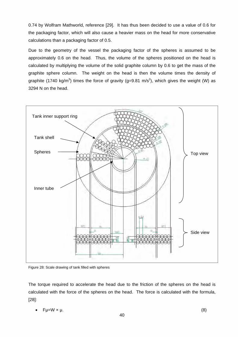
changes the packaging factor. With the use of Figure 28, a scale drawing of the tank filled with
scaled spheres, the packaging factor was calculated. On this drawing the spheres were
counted and their total volume calculated. The filled volume of the tank was then calculated.
Only a quarter of the tank was used and then multiplied by four to get the total volume. This
was done for both a top view and a bottom view. For the top view a packaging factor of 0.49
was calculated and a packaging factor of 0.51 was calculated for the side view, thus
approximately 0.5.
A packaging factor of 0.5 means that half the tank is filled with spheres and the remainder filled
with gas. It has however been assumed that this value is very low against the given value of
40
0.74 by Wolfram Mathworld, reference [29]. It has thus been decided to use a value of 0.6 for
the packaging factor, which will also cause a heavier mass on the head for more conservative
calculations than a packaging factor of 0.5.
Due to the geometry of the vessel the packaging factor of the spheres is assumed to be
approximately 0.6 on the head. Thus, the volume of the spheres positioned on the head is
calculated by multiplying the volume of the solid graphite column by 0.6 to get the mass of the
graphite sphere column. The weight on the head is then the volume times the density of
graphite (1740 kg/m3) times the force of gravity (g=9.81 m/s2), which gives the weight (W) as
3294 N on the head.
Figure 28: Scale drawing of tank filled with spheres
The torque required to accelerate the head due to the friction of the spheres on the head is
calculated with the force of the spheres on the head. The force is calculated with the formula,
[28]:
Fμ=W × μ. (8)
Tank shell
Tank inner support ring
Inner tube
Spheres Top view
Side view

41
The pressure (pμ) on the head is a function of the force on the head and the area of the head
where the force is applied. The torque required to turn the head with the spheres on the head is
then calculated with equation 9, [28]:
Tμ=r × pμ. (9)
However, the since the radius of the head is increasing, starting at the head centre and then
increases to 320 mm, the torque can be calculated by integrating over the radius of the head
top area, as indicated in Figure 29.
Figure 29: Integrating over the radius of the head
The equation that is used to calculate the torque is:
(10)
The torque required against the friction is calculated as 211 Nm by equation (10).
·
; where α = 1.65 m/s2 [28] (11)
0.5 · · ; where J = 14.545 m2·kg [28] (12)
· ; where T = 24 Nm [28] (13)
The total torque required for accelerating the head can be found by adding the accelerating
torque and friction torque values: 24 Nm + 211 Nm = 235 Nm. (14)
The next step is to determine what the impact force of the rotating head is on the sphere if a
sphere is clamped. There are three conditions applicable to the head:
First is the torque required to accelerate the head;
Second, to maintain head optimum rotational speed;
Third is the rotating head striking a sphere.

42
The force on the sphere that is now clamped between the head and the housing, as indicated in
Figure 25, is a function of the momentum of the head as well as the stall torque force of the
actuator applied to the rotation of the head. A conservative approach is to do this calculation
without spheres on the head, because the spheres will have a dampening effect on the impact
of the head on the sphere, due to the friction brake between the rotating head and the spheres
on top of the head.
It is required to rotate the head with only enough torque to overcome the friction in the rotating
parts of the unloading mechanism. However, to accelerate the head from its parked position a
high torque is required. Therefore the head is driven through a variable electromechanical
torque limiter. When the head is to be accelerated the torque limiter is set to a high setting
enough to overcome the full friction of spheres on the head together with the torque required to
accelerate the head.
When the head speed is reached the torque is reduced to a torque setting just above the torque
required to overcome friction on the head since acceleration is not required. According to
calculations a torque setting of 211 Nm corresponds with the friction, therefore a torque limiter
with a maximum torque setting of 313 Nm has been selected. This selection is the closest
standard for off-the-shelf torque limiters to the required minimum of 235 Nm, thus the torque
limiter will be operated at a maximum of 235 Nm at acceleration of the head, and then reduced
to 211 Nm after acceleration.
When the head strikes a miss fed sphere, the force of the actuator is limited to a minimum
required force for rotating the head. However, the impact has been simulated mathematically to
predict what is going to happen at impact. In paragraph 8 of Appendix A it was calculated that
an impact occurring in a time duration equal to or less than 0.003 s will result in a force higher
than 18 kN, enough to break the sphere. This force is the result of the momentum of the
rotating head.
It can be concluded that the momentum of the head alone is enough to cut the sphere at
impact. The conservative assumption is that there are only a few spheres on the head, thus
friction between the head and the spheres can be ignored at the time of impact, which causes
the highest force on the sphere due to the absence of the friction brake between spheres on the
head and head itself. It has therefore been decided to introduce an impact limiter to the design
to protect the sphere.
a. Main actuator components
The characteristic of the actuator that rotates the head is required to design the impact
limiter. Based on the 235 Nm, as calculated above, and 10 min-1 rotational speed, an
actuator drive was selected. The following components are required for the actuator:
Actuator drive;
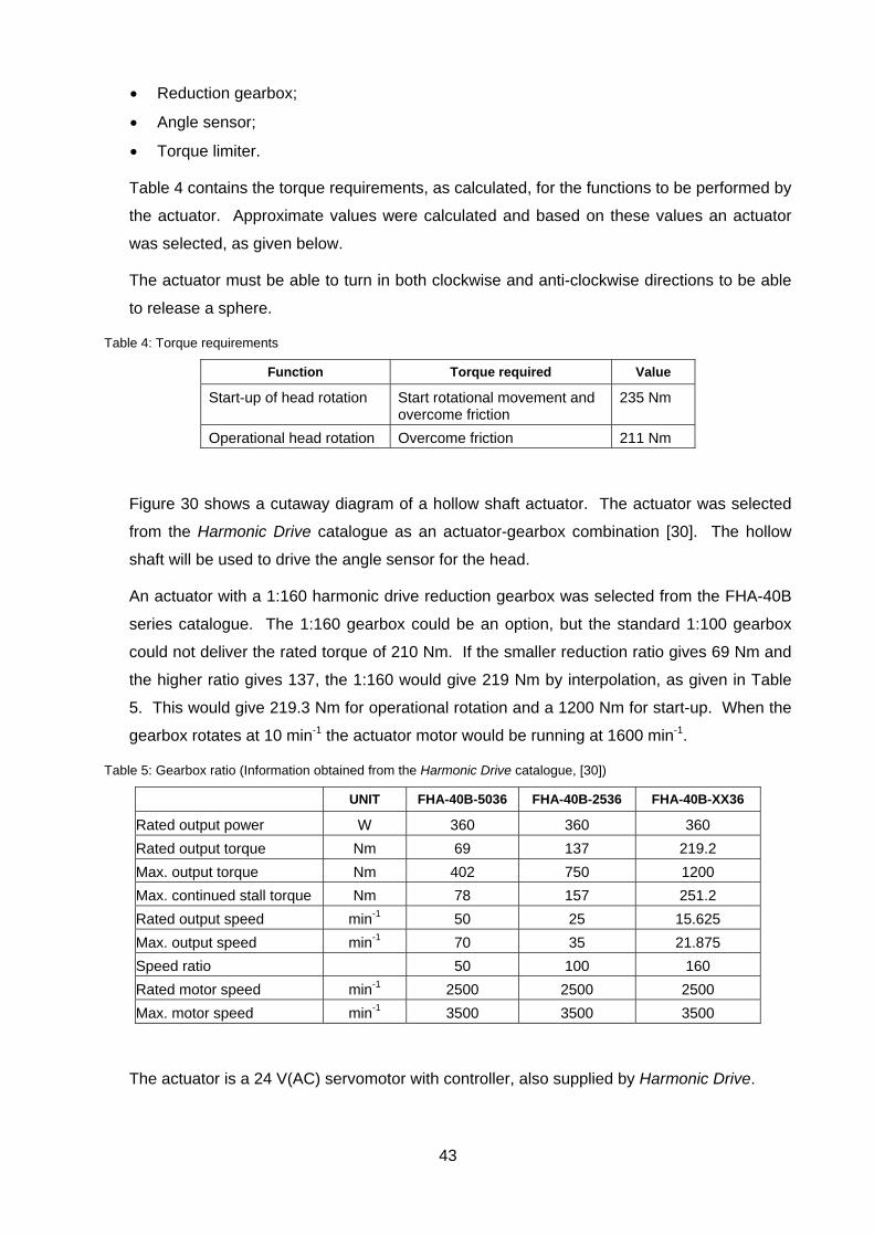
43
Reduction gearbox;
Angle sensor;
Torque limiter.
Table 4 contains the torque requirements, as calculated, for the functions to be performed by
the actuator. Approximate values were calculated and based on these values an actuator
was selected, as given below.
The actuator must be able to turn in both clockwise and anti-clockwise directions to be able
to release a sphere.
Table 4: Torque requirements
Function Torque required Value
Start-up of head rotation Start rotational movement and overcome friction
235 Nm
Operational head rotation Overcome friction 211 Nm
Figure 30 shows a cutaway diagram of a hollow shaft actuator. The actuator was selected
from the Harmonic Drive catalogue as an actuator-gearbox combination [30]. The hollow
shaft will be used to drive the angle sensor for the head.
An actuator with a 1:160 harmonic drive reduction gearbox was selected from the FHA-40B
series catalogue. The 1:160 gearbox could be an option, but the standard 1:100 gearbox
could not deliver the rated torque of 210 Nm. If the smaller reduction ratio gives 69 Nm and
the higher ratio gives 137, the 1:160 would give 219 Nm by interpolation, as given in Table
5. This would give 219.3 Nm for operational rotation and a 1200 Nm for start-up. When the
gearbox rotates at 10 min-1 the actuator motor would be running at 1600 min-1.
Table 5: Gearbox ratio (Information obtained from the Harmonic Drive catalogue, [30])
UNIT FHA-40B-5036 FHA-40B-2536 FHA-40B-XX36
Rated output power W 360 360 360
Rated output torque Nm 69 137 219.2
Max. output torque Nm 402 750 1200
Max. continued stall torque Nm 78 157 251.2
Rated output speed min-1 50 25 15.625
Max. output speed min-1 70 35 21.875
Speed ratio 50 100 160
Rated motor speed min-1 2500 2500 2500
Max. motor speed min-1 3500 3500 3500
The actuator is a 24 V(AC) servomotor with controller, also supplied by Harmonic Drive.
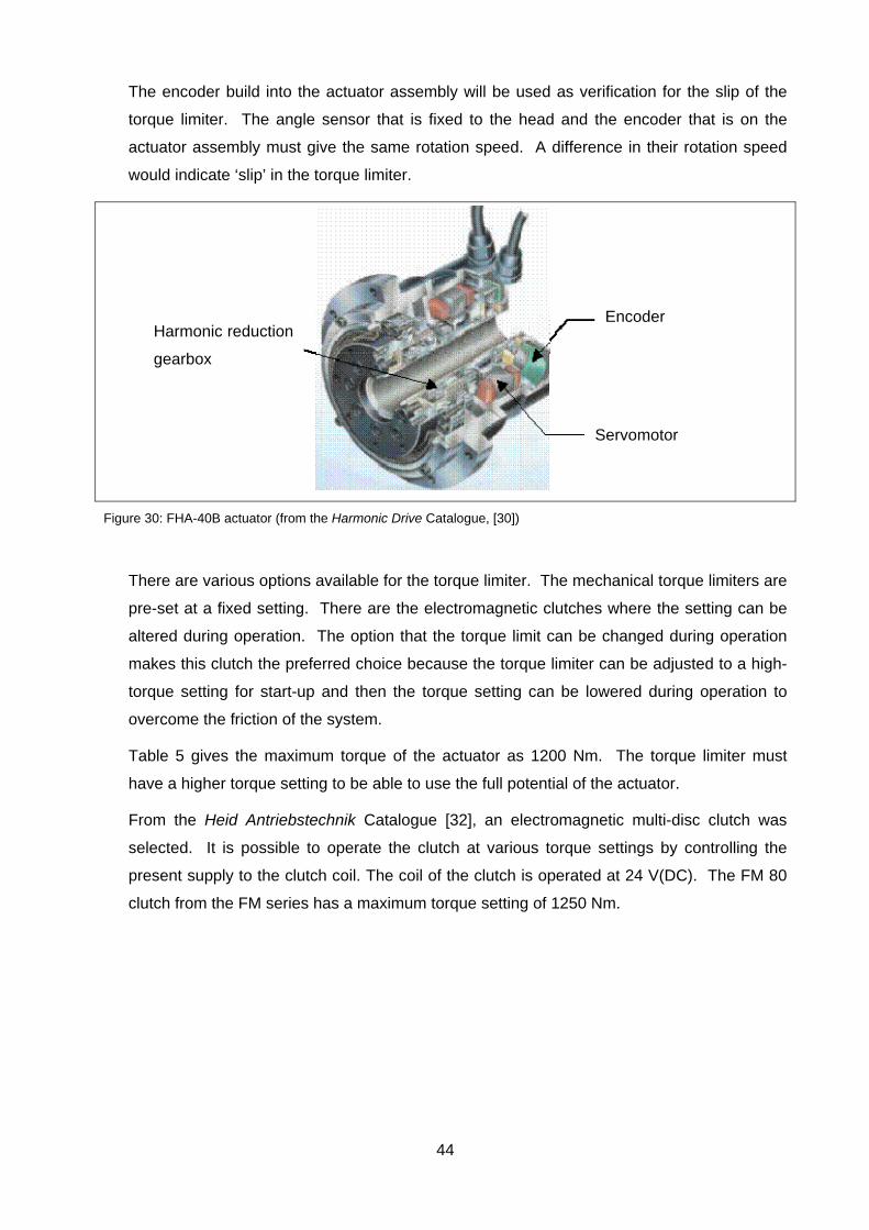
44
The encoder build into the actuator assembly will be used as verification for the slip of the
torque limiter. The angle sensor that is fixed to the head and the encoder that is on the
actuator assembly must give the same rotation speed. A difference in their rotation speed
would indicate ‘slip’ in the torque limiter.
Figure 30: FHA-40B actuator (from the Harmonic Drive Catalogue, [30])
There are various options available for the torque limiter. The mechanical torque limiters are
pre-set at a fixed setting. There are the electromagnetic clutches where the setting can be
altered during operation. The option that the torque limit can be changed during operation
makes this clutch the preferred choice because the torque limiter can be adjusted to a high-
torque setting for start-up and then the torque setting can be lowered during operation to
overcome the friction of the system.
Table 5 gives the maximum torque of the actuator as 1200 Nm. The torque limiter must
have a higher torque setting to be able to use the full potential of the actuator.
From the Heid Antriebstechnik Catalogue [32], an electromagnetic multi-disc clutch was
selected. It is possible to operate the clutch at various torque settings by controlling the
present supply to the clutch coil. The coil of the clutch is operated at 24 V(DC). The FM 80
clutch from the FM series has a maximum torque setting of 1250 Nm.
Encoder
Servomotor
Harmonic reduction
gearbox
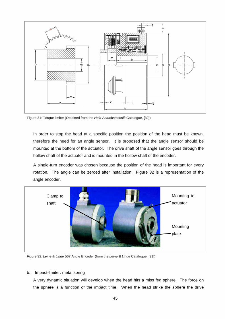
45
Figure 31: Torque limiter (Obtained from the Heid Antriebstechnik Catalogue, [32])
In order to stop the head at a specific position the position of the head must be known,
therefore the need for an angle sensor. It is proposed that the angle sensor should be
mounted at the bottom of the actuator. The drive shaft of the angle sensor goes through the
hollow shaft of the actuator and is mounted in the hollow shaft of the encoder.
A single-turn encoder was chosen because the position of the head is important for every
rotation. The angle can be zeroed after installation. Figure 32 is a representation of the
angle encoder.
Figure 32: Leine & Linde 567 Angle Encoder (from the Leine & Linde Catalogue, [31])
b. Impact-limiter: metal spring
A very dynamic situation will develop when the head hits a miss fed sphere. The force on
the sphere is a function of the impact time. When the head strike the sphere the drive
Mounting to
actuator
Mounting
plate
Clamp to
shaft

46
torque from the actuator is increased until a maximum torque of 1200 Nm (from Table 5)
where after the actuator drive torque falls to the continuous torque setting of 251 Nm (from
Table 5). The actuator is thus still driving the head into the sphere when the head has come
to a standstill after full depression of the spring. To demonstrate what was happening a
mathematical model was developed, Appendix A, and is described in the next section.
Since the impact on the sphere is a function of the deceleration of the head, the algorithm
calculates the incremental speed according to the deceleration that occurs. The velocity of
the head is calculated with equation 15:
· ∆ [28] (15)
With the velocity after time increment 1, the new position of the head is calculated with
equation 16:
·· .
· ∆ [28] (16)
The new position of equation (16) is then used to calculate the force on the sphere with a
spring k-value 1.
The algorithm methodology with a spring is described in paragraph 9.2 of Appendix A. Each
time the model was run, a different k-value for the spring was used to determine the effect of
the spring k-value on the system under impact. Table 6 shows that by increasing the k-
value of the spring, the force on the sphere increases, which corresponds with the spring
equation:
F=k × Δx. (17)
The lower k-value provides better protection for the sphere because it increases the time of
impact. The resulting force, together with the spring displacement, is then used as a direct
input for the spring design.
Table 6: Simulation results of head reactions after impact with different k-values
Spring Maximum spring
compression Maximum head return
Maximum force on sphere
k-value [kN/m]
Time [s}
Distance[mm]
Time [s}
Distance[mm]
Time [s}
Force [N]
2000 0.01361 2.9634 0.05127 -2.5382 0.01364 5.9268 4000 0.00951 2.0665 0.0446 -3.2845 0.00957 8.2663 6000 0.00775 1.6769 0.04156 -3.608 0.00775 10.061 8000 0.00675 1.4468 0.03991 -3.799 0.00669 11.575 10000 0.00597 1.2908 0.03895 -3.9284 0.00601 12.908 12000 0.00545 1.1761 0.03811 -4.0235 0.00547 14.114 14000 0.00505 1.0873 0.03741 -4.0971 0.00507 15.222 16000 0.00474 1.0159 0.03684 -4.1562 0.00473 16.254 18000 0.00442 0.95674 0.03651 -4.2052 0.00448 17.222
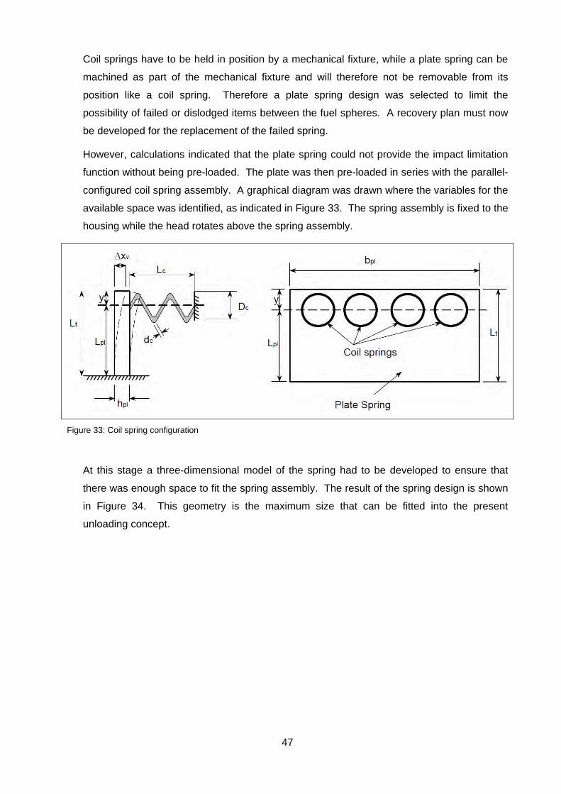
47
Coil springs have to be held in position by a mechanical fixture, while a plate spring can be
machined as part of the mechanical fixture and will therefore not be removable from its
position like a coil spring. Therefore a plate spring design was selected to limit the
possibility of failed or dislodged items between the fuel spheres. A recovery plan must now
be developed for the replacement of the failed spring.
However, calculations indicated that the plate spring could not provide the impact limitation
function without being pre-loaded. The plate was then pre-loaded in series with the parallel-
configured coil spring assembly. A graphical diagram was drawn where the variables for the
available space was identified, as indicated in Figure 33. The spring assembly is fixed to the
housing while the head rotates above the spring assembly.
Figure 33: Coil spring configuration
At this stage a three-dimensional model of the spring had to be developed to ensure that
there was enough space to fit the spring assembly. The result of the spring design is shown
in Figure 34. This geometry is the maximum size that can be fitted into the present
unloading concept.
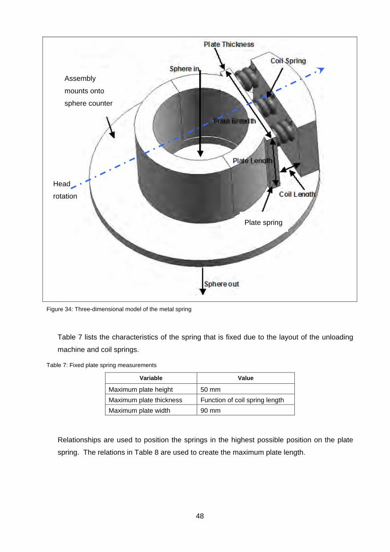
48
Figure 34: Three-dimensional model of the metal spring
Table 7 lists the characteristics of the spring that is fixed due to the layout of the unloading
machine and coil springs.
Table 7: Fixed plate spring measurements
Variable Value
Maximum plate height 50 mm
Maximum plate thickness Function of coil spring length
Maximum plate width 90 mm
Relationships are used to position the springs in the highest possible position on the plate
spring. The relations in Table 8 are used to create the maximum plate length.
Head
rotation
Assembly
mounts onto
sphere counter
Plate spring
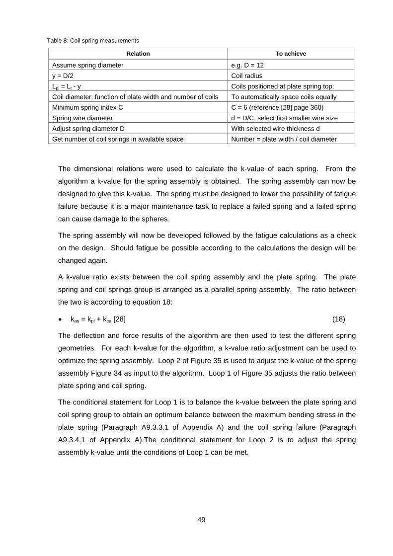
49
Table 8: Coil spring measurements
Relation To achieve
Assume spring diameter e.g. D = 12
y = D/2 Coil radius
Lpl = Lt - y Coils positioned at plate spring top:
Coil diameter: function of plate width and number of coils To automatically space coils equally
Minimum spring index C C = 6 (reference [28] page 360)
Spring wire diameter d = D/C, select first smaller wire size
Adjust spring diameter D With selected wire thickness d
Get number of coil springs in available space Number = plate width / coil diameter
The dimensional relations were used to calculate the k-value of each spring. From the
algorithm a k-value for the spring assembly is obtained. The spring assembly can now be
designed to give this k-value. The spring must be designed to lower the possibility of fatigue
failure because it is a major maintenance task to replace a failed spring and a failed spring
can cause damage to the spheres.
The spring assembly will now be developed followed by the fatigue calculations as a check
on the design. Should fatigue be possible according to the calculations the design will be
changed again.
A k-value ratio exists between the coil spring assembly and the plate spring. The plate
spring and coil springs group is arranged as a parallel spring assembly. The ratio between
the two is according to equation 18:
kas = kpl + kca [28] (18)
The deflection and force results of the algorithm are then used to test the different spring
geometries. For each k-value for the algorithm, a k-value ratio adjustment can be used to
optimize the spring assembly. Loop 2 of Figure 35 is used to adjust the k-value of the spring
assembly Figure 34 as input to the algorithm. Loop 1 of Figure 35 adjusts the ratio between
plate spring and coil spring.
The conditional statement for Loop 1 is to balance the k-value between the plate spring and
coil spring group to obtain an optimum balance between the maximum bending stress in the
plate spring (Paragraph A9.3.3.1 of Appendix A) and the coil spring failure (Paragraph
A9.3.4.1 of Appendix A).The conditional statement for Loop 2 is to adjust the spring
assembly k-value until the conditions of Loop 1 can be met.
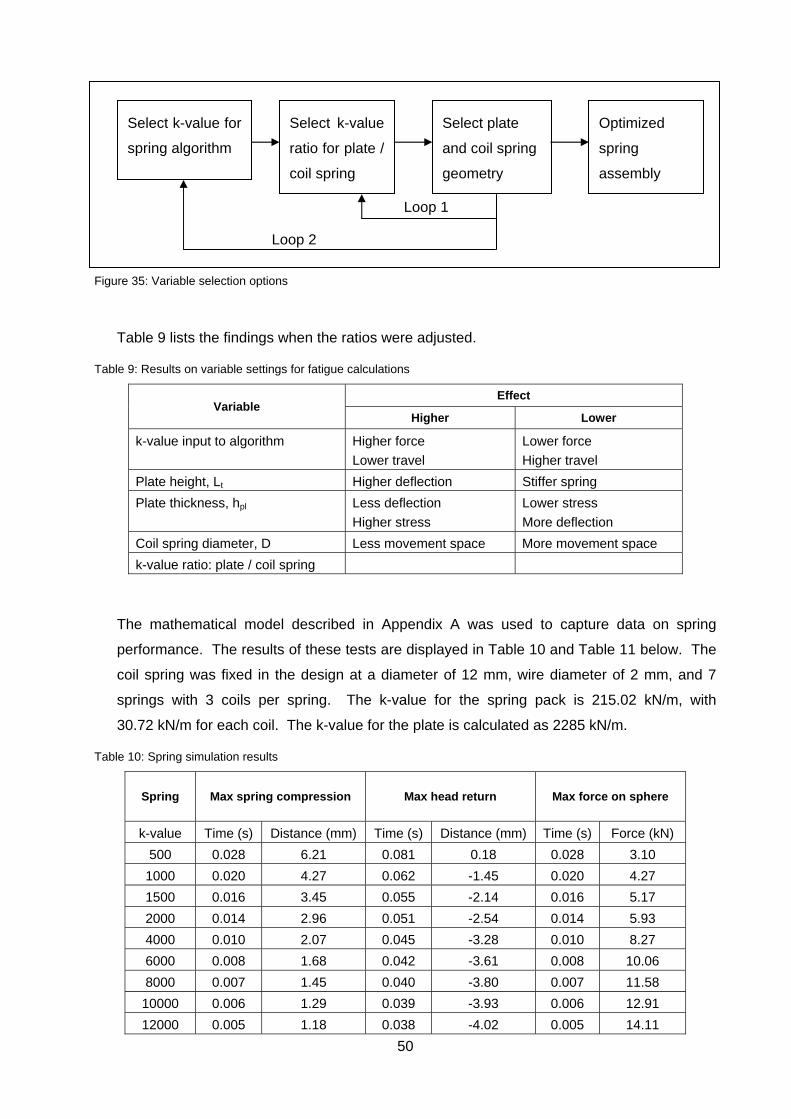
50
Figure 35: Variable selection options
Table 9 lists the findings when the ratios were adjusted.
Table 9: Results on variable settings for fatigue calculations
Variable Effect
Higher Lower
k-value input to algorithm Higher force
Lower travel
Lower force
Higher travel
Plate height, Lt Higher deflection Stiffer spring
Plate thickness, hpl Less deflection
Higher stress
Lower stress
More deflection
Coil spring diameter, D Less movement space More movement space
k-value ratio: plate / coil spring
The mathematical model described in Appendix A was used to capture data on spring
performance. The results of these tests are displayed in Table 10 and Table 11 below. The
coil spring was fixed in the design at a diameter of 12 mm, wire diameter of 2 mm, and 7
springs with 3 coils per spring. The k-value for the spring pack is 215.02 kN/m, with
30.72 kN/m for each coil. The k-value for the plate is calculated as 2285 kN/m.
Table 10: Spring simulation results
Spring Max spring compression Max head return Max force on sphere
k-value Time (s) Distance (mm) Time (s) Distance (mm) Time (s) Force (kN)
500 0.028 6.21 0.081 0.18 0.028 3.10
1000 0.020 4.27 0.062 -1.45 0.020 4.27
1500 0.016 3.45 0.055 -2.14 0.016 5.17
2000 0.014 2.96 0.051 -2.54 0.014 5.93
4000 0.010 2.07 0.045 -3.28 0.010 8.27
6000 0.008 1.68 0.042 -3.61 0.008 10.06
8000 0.007 1.45 0.040 -3.80 0.007 11.58
10000 0.006 1.29 0.039 -3.93 0.006 12.91
12000 0.005 1.18 0.038 -4.02 0.005 14.11
Select k-value for
spring algorithm
Select plate
and coil spring
geometry
Select k-value
ratio for plate /
coil spring
Loop 1
Loop 2
Optimized
spring
assembly

51
Table 11: Spring simulation results (continued)
Spring Coil spring
failure Plate bending
stress Plate
thickness Spring material
space filling
Total space
required
k-value t = s tm=Sy MPa mm mm mm
500 yes no 1533 1.96 7.96 14.17
1000 no no 1480 2.75 8.75 13.02
1500 n no 1407 2.34 8.34 11.79
2000 no no 1350 3.61 9.61 12.57
4000 no no 1209 4.64 10.64 12.71
6000 no no 1130 5.35 11.35 13.03
8000 no no 1077 5.91 11.91 13.36
10000 no no 1067 6.37 12.37 13.66
12000 no no 1005 6.78 12.78 13.96
Table 12 gives the results where the coil spring was fixed at a diameter of 8 mm, wire
diameter of 1.3 mm, and at 11 springs of 3 coils each. The k-value for the test spring pack is
219.63 kN/m, and 19.066 kN/m for each coil.
Table 12: Spring simulation results (continued)
Spring Coil spring
failure Plate bending
stress Plate
thickness
Spring material
space filling
Total space required
k-value t = s tm=Sy MPa mm mm mm
500 yes yes 1525 1.95 5.85 12.06
1000 yes no 1477 2.74 6.64 10.91
1500 no no 1405 3.24 7.14 10.59
2000 no no 1349 3.61 7.51 10.47
4000 no no 1209 4.64 8.54 10.61
6000 no no 1130 5.35 9.25 10.93
8000 no no 1076 5.9 9.80 11.25
10000 no no 1036 6.37 10.27 11.56
12000 no no 1005 6.78 10.68 11.86
The smallest spring assembly space requirement in Table 12 is where the spring assembly
has a k-value of 2000 kN/m, where 10.47 mm is required to position the spring assembly.
Of this 10.47 mm the spring plate takes up 3.6 mm (plate thickness hpl as indicated in Figure
36) and the compressed coil a length of 3 × 1.3 = 3.9 mm, totalling hardware that takes up
7.5 mm of the 10.47 mm. According to fatigue calculations the coil springs will not fail, but
the bending stress on the plate spring is very high. The high bending stress will require

52
special materials, for example the yield stress of EN24 steel is only 650 MPa according to
Shelley Steels [33].
Figure 36: Spring installation space requirement
The metal spring works, but the bending stresses in the materials are high. The high
stresses make the design a marginal design and definitely not robust. Regular
maintenance will be required which is expensive in the nuclear industry. It has therefore
been decided to discontinue further development work on the metal spring concept.
c. Impact-limiter: silicone spring
To expand on the gravity concept the possibility of using a silicone spring was investigated.
The silicone spring was placed in the same position as the metal spring. Figure 37 shows
the three dimensional model of the silicone spring where the silicone is housed in a metal
ring.
The silicone spring will not suddenly collapse as happened with the failure of the metal
spring, but the silicone will degrade over time due to the radioactive environment, [23], [24].
Therefore the silicone must be replaced at certain maintenance intervals.
Free length of spring
assembly (10.47 mm) Compressed length of spring
assembly (7.51 mm)
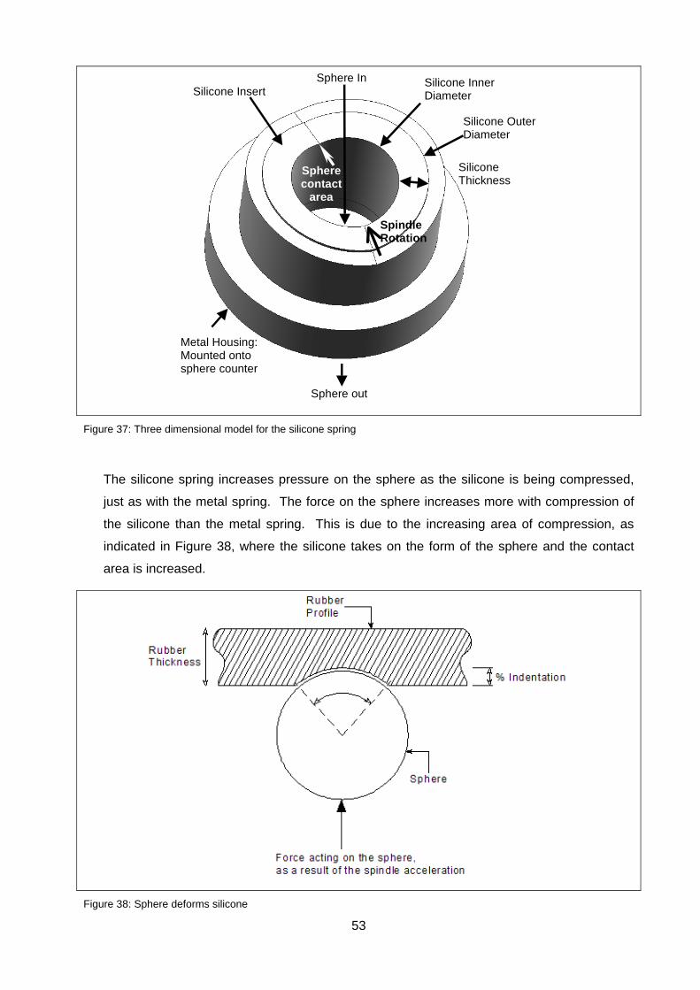
53
Figure 37: Three dimensional model for the silicone spring
The silicone spring increases pressure on the sphere as the silicone is being compressed,
just as with the metal spring. The force on the sphere increases more with compression of
the silicone than the metal spring. This is due to the increasing area of compression, as
indicated in Figure 38, where the silicone takes on the form of the sphere and the contact
area is increased.
Figure 38: Sphere deforms silicone
Sphere In Silicone Insert
Silicone Thickness
Metal Housing: Mounted onto sphere counter
Sphere out
Spindle Rotation
Sphere contact
area
Silicone Outer Diameter
Silicone Inner Diameter

54
The same algorithm that was used for the metal spring calculations was used for the silicone
spring. However, in this case the formula was altered to make provision for the silicone
properties and the increasing force on the spring due to the increasing contact area between
the silicone and the sphere.
To calculate the increasing force on the sphere due to the increasing area of contact, a
relation was required in the algorithm to take this phenomenon into account.
With reference to Figure 39, the increasing force on the sphere can be described
mathematically with the following equation:
% · ·
% ·
(19)
Equation 19 is derived from:
The area of contact between the sphere and the silicone is:
o A = (π × d2)/4, (20)
o Where d = 2 × R × Sin θ. (21)
The increasing contact area is a function of the increasing indentation,
o Δx = sphere radius – (%compression / 100 × the rubber thickness) × θ. (22)
The angle θ is calculated by:
o Cosθ = (head radius – Δx) / sphere radius. (23)
The resulting equation becomes equation 19
The force on the sphere is calculated with the equation:
o pressure = force / area (24)
The percentage indentation is calculated as a function of Δx where the:
o indentation% = (Δx / rubber thickness) × 100 (25
The k-value of the silicone spring is calculated by the (force as a function of %
indentation, %C, of the rubber again as a function of Δx) / Δx, or in formula format as
o ∆ % ∆
∆ (26)

55
Figure 39: Mathematical representation of silicone deformation
A typical result is shown in Figure 40, which depends on the silicone hardness used.
Figure 40: Silicone compression pressure increase
The algorithm was altered to calculate the k-value for the silicone spring. Figure 41 shows
the improved algorithm. The mathematical calculations with this algorithm can be followed
in Appendix A.
0 5 105 1 10
4 1.5 104
0
100
200
300
Displacement [m]
For
ce [
N]
Fr %c
x r
· sin
· % 100⁄
· cos
Angle θ°
(degrees)
Contact angle 2θ°
(degrees)
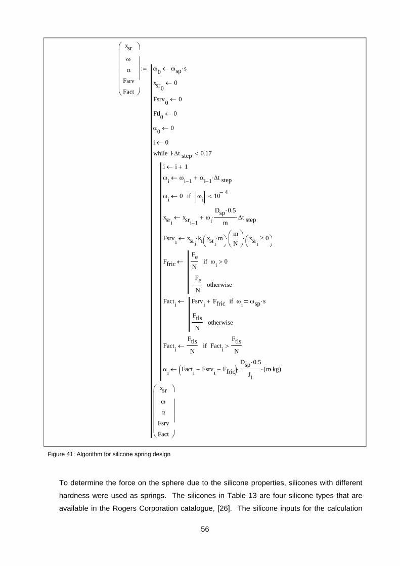
56
Figure 41: Algorithm for silicone spring design
To determine the force on the sphere due to the silicone properties, silicones with different
hardness were used as springs. The silicones in Table 13 are four silicone types that are
available in the Rogers Corporation catalogue, [26]. The silicone inputs for the calculation
xsr
Fsrv
Fact
0
sp s
xsr00
Fsrv0
0
Ftl0
0
0
0
i 0
i i 1
i
i 1
i 1 t step
i
0 i
104
if
xsrixsri 1
i
Dsp 0.5
m t step
Fsrvi
xsrikr xsri
m
m
N
xsri0
Ffric
Fe
N
i0if
Fe
N otherwise
Facti
Fsrvi
Ffric i
sp sif
Ftls
Notherwise
Facti
Ftls
N Fact
i
Ftls
Nif
i
Facti
Fsrvi
Ffric Dsp 0.5
Jt m kg( )
i t step 0.17while
xsr
Fsrv
Fact
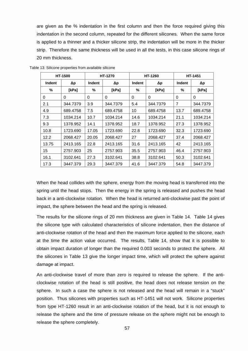
57
are given as the % indentation in the first column and then the force required giving this
indentation in the second column, repeated for the different silicones. When the same force
is applied to a thinner and a thicker silicone strip, the indentation will be more in the thicker
strip. Therefore the same thickness will be used in all the tests, in this case silicone rings of
20 mm thickness.
Table 13: Silicone properties from available silicone
HT-1500 HT-1270 HT-1260 HT-1451
Indent Δp Indent Δp Indent Δp Indent Δp
% [kPa] % [kPa] % [kPa] % [kPa]
0 0 0 0 0 0 0 0
2.1 344.7379 3.9 344.7379 5.4 344.7379 7 344.7379
4.9 689.4758 7.5 689.4758 10 689.4758 13.7 689.4758
7.3 1034.214 10.7 1034.214 14.6 1034.214 21.1 1034.214
9.3 1378.952 14.1 1378.952 18.7 1378.952 27.3 1378.952
10.8 1723.690 17.05 1723.690 22.8 1723.690 32.3 1723.690
12.2 2068.427 20.05 2068.427 27 2068.427 37.4 2068.427
13.75 2413.165 22.8 2413.165 31.6 2413.165 42 2413.165
15 2757.903 25 2757.903 35.5 2757.903 46.4 2757.903
16.1 3102.641 27.3 3102.641 38.8 3102.641 50.3 3102.641
17.3 3447.379 29.3 3447.379 41.6 3447.379 54.8 3447.379
When the head collides with the sphere, energy from the moving head is transferred into the
spring until the head stops. Then the energy in the spring is released and pushes the head
back in a anti-clockwise rotation. When the head is returned anti-clockwise past the point of
impact, the sphere between the head and the spring is released.
The results for the silicone rings of 20 mm thickness are given in Table 14. Table 14 gives
the silicone type with calculated characteristics of silicone indentation, then the distance of
anti-clockwise rotation of the head and then the maximum force applied to the silicone, each
at the time the action value occurred. The results, Table 14, show that it is possible to
obtain impact duration of longer than the required 0.003 seconds to protect the sphere. All
the silicones in Table 13 give the longer impact time, which will protect the sphere against
damage at impact.
An anti-clockwise travel of more than zero is required to release the sphere. If the anti-
clockwise rotation of the head is still positive, the head does not release tension on the
sphere. In such a case the sphere is not released and the head will remain in a “stuck”
position. Thus silicones with properties such as HT-1451 will not work. Silicone properties
from type HT-1260 result in an anti-clockwise rotation of the head, but it is not enough to
release the sphere and the time of pressure release on the sphere might not be enough to
release the sphere completely.
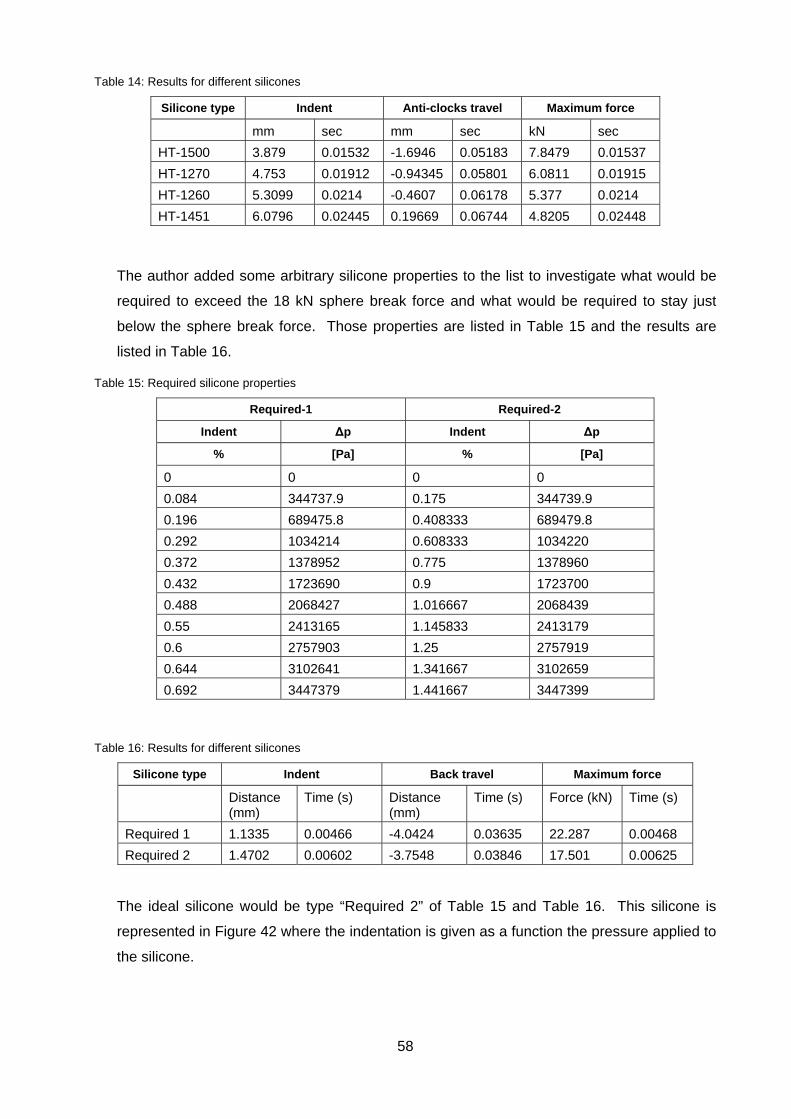
58
Table 14: Results for different silicones
Silicone type Indent Anti-clocks travel Maximum force
mm sec mm sec kN sec
HT-1500 3.879 0.01532 -1.6946 0.05183 7.8479 0.01537
HT-1270 4.753 0.01912 -0.94345 0.05801 6.0811 0.01915
HT-1260 5.3099 0.0214 -0.4607 0.06178 5.377 0.0214
HT-1451 6.0796 0.02445 0.19669 0.06744 4.8205 0.02448
The author added some arbitrary silicone properties to the list to investigate what would be
required to exceed the 18 kN sphere break force and what would be required to stay just
below the sphere break force. Those properties are listed in Table 15 and the results are
listed in Table 16.
Table 15: Required silicone properties
Required-1 Required-2
Indent Δp Indent Δp
% [Pa] % [Pa]
0 0 0 0
0.084 344737.9 0.175 344739.9
0.196 689475.8 0.408333 689479.8
0.292 1034214 0.608333 1034220
0.372 1378952 0.775 1378960
0.432 1723690 0.9 1723700
0.488 2068427 1.016667 2068439
0.55 2413165 1.145833 2413179
0.6 2757903 1.25 2757919
0.644 3102641 1.341667 3102659
0.692 3447379 1.441667 3447399
Table 16: Results for different silicones
Silicone type Indent Back travel Maximum force
Distance (mm)
Time (s) Distance (mm)
Time (s) Force (kN) Time (s)
Required 1 1.1335 0.00466 -4.0424 0.03635 22.287 0.00468
Required 2 1.4702 0.00602 -3.7548 0.03846 17.501 0.00625
The ideal silicone would be type “Required 2” of Table 15 and Table 16. This silicone is
represented in Figure 42 where the indentation is given as a function the pressure applied to
the silicone.
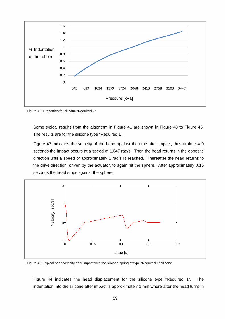
59
Figure 42: Properties for silicone “Required 2”
Some typical results from the algorithm in Figure 41 are shown in Figure 43 to Figure 45.
The results are for the silicone type “Required 1”.
Figure 43 indicates the velocity of the head against the time after impact, thus at time = 0
seconds the impact occurs at a speed of 1.047 rad/s. Then the head returns in the opposite
direction until a speed of approximately 1 rad/s is reached. Thereafter the head returns to
the drive direction, driven by the actuator, to again hit the sphere. After approximately 0.15
seconds the head stops against the sphere.
Figure 43: Typical head velocity after impact with the silicone spring of type “Required 1” silicone
Figure 44 indicates the head displacement for the silicone type “Required 1”. The
indentation into the silicone after impact is approximately 1 mm where after the head turns in
0
0.2
0.4
0.6
0.8
1
1.2
1.4
1.6
345 689 1034 1379 1724 2068 2413 2758 3103 3447
Series1
0 0.05 0.1 0.15 0.21
0
1
2
Time [s]
Vel
ocit
y [r
ad/s
]
Pressure [kPa]
% Indentation
of the rubber
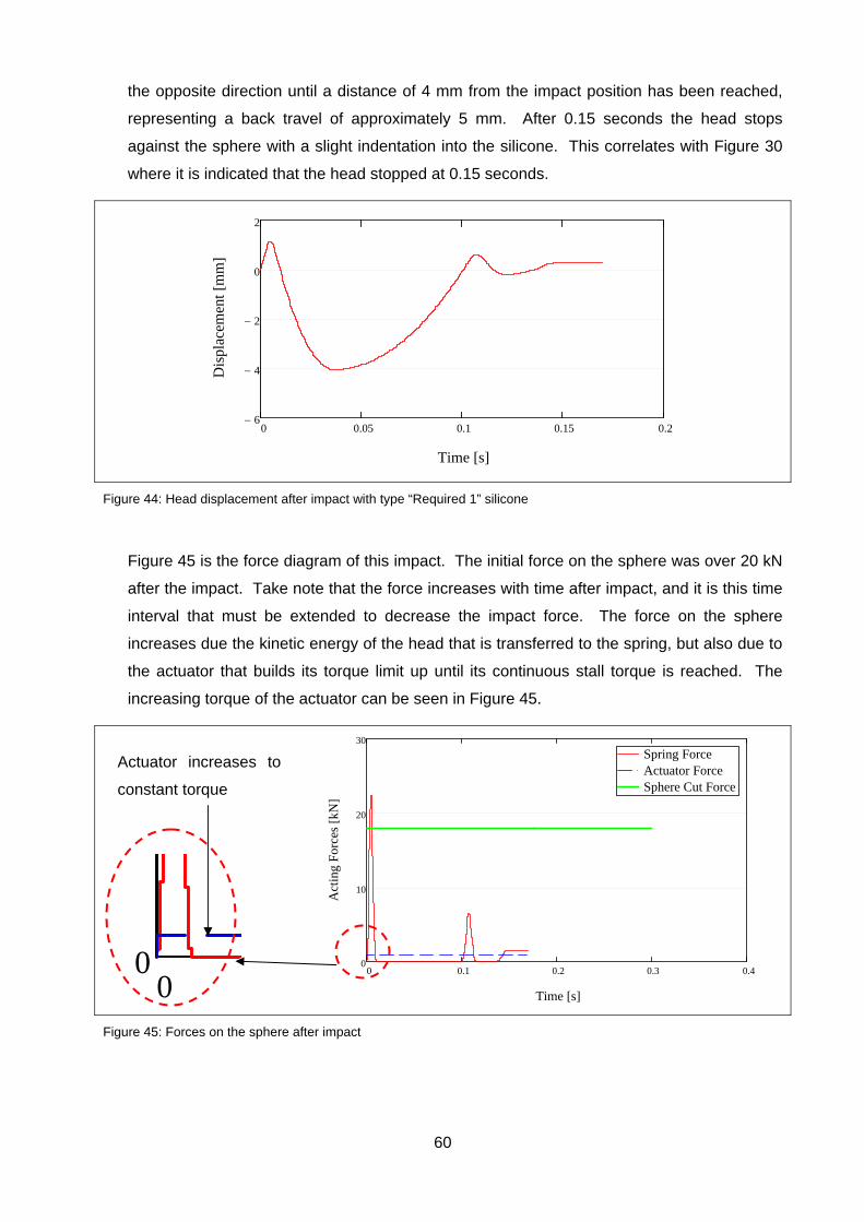
60
the opposite direction until a distance of 4 mm from the impact position has been reached,
representing a back travel of approximately 5 mm. After 0.15 seconds the head stops
against the sphere with a slight indentation into the silicone. This correlates with Figure 30
where it is indicated that the head stopped at 0.15 seconds.
Figure 44: Head displacement after impact with type “Required 1” silicone
Figure 45 is the force diagram of this impact. The initial force on the sphere was over 20 kN
after the impact. Take note that the force increases with time after impact, and it is this time
interval that must be extended to decrease the impact force. The force on the sphere
increases due the kinetic energy of the head that is transferred to the spring, but also due to
the actuator that builds its torque limit up until its continuous stall torque is reached. The
increasing torque of the actuator can be seen in Figure 45.
Figure 45: Forces on the sphere after impact
0 0.05 0.1 0.15 0.26
4
2
0
2
Time [s]
Dis
plac
emen
t [m
m]
00
0 0.1 0.2 0.3 0.40
10
20
30
Spring ForceActuator ForceSphere Cut Force
Time [s]
Act
ing
For
ces
[kN
]
Actuator increases to
constant torque

61
Silicone apparently provides good sphere protection properties and silicones with the
required properties are available. The preferred silicones must have the same properties as
that provided by HT-1270 and HT-1500 provided by the Rogers Corporation.
4.2.3 CONCEPT DESIGN STATUS AND COMPLIANCE VERIFICATION
Spheres are removed from the sphere bed at the required indexing sequence. Both the silicone
and metal spring protect the sphere against damage. However, the springs will require
inspections and maintenance during the operational lifetime of the tank unloading device. Table
17 lists the criteria and the evaluation of the existing concept status against the criteria.
Table 17: Evaluating the concept status
Criteria Advantage Disadvantage
Sphere removal from sphere bed
333 spheres / hr
Unload rhythm Very good, every 7 seconds
Sphere damage Spheres could be damaged by scissor action between head and housing
Broken sphere separation Only dust, not larger pieces
Maintenance requirement Regular inspections will be required and most likely maintenance to replace the springs.
Maintenance possible No, head diameter too big for removal
Dust generation Dust generation is limited due to slow rotational speed
Nuclear safety When a sphere is broken a DiD barrier is broken
4.2.4 FURTHER GRAVITY CONCEPT DEVELOPMENT
Due to the inspection and maintenance requirements the head must be removable. The head is
however not removable through the maintenance pipe. The maintenance pipe has an inner
diameter of 400 mm as indicated in Figure 28. Therefore the head diameter must be reduced to
less than 400 mm. This concept will be developed further to limit the maintenance needs, rather
than to increase maintainability. The spring assembly is the part of the tank unloading device
that will need inspection and maintenance. If the need for the spring can be removed, the need
for spring maintenance will also be removed.
It has however still been decided to decrease the head diameter to make the head removable
through the maintenance pipe. Due to the smaller head diameter bridge-forming can possibly
occur. Bridge-forming can be limited or even prevented by the maintenance pipe that can be
positioned in such a way that it prevents large sphere loads in the head, as indicated in Figure
46, but this must be verified through testing. This is the same principle that is used in bird
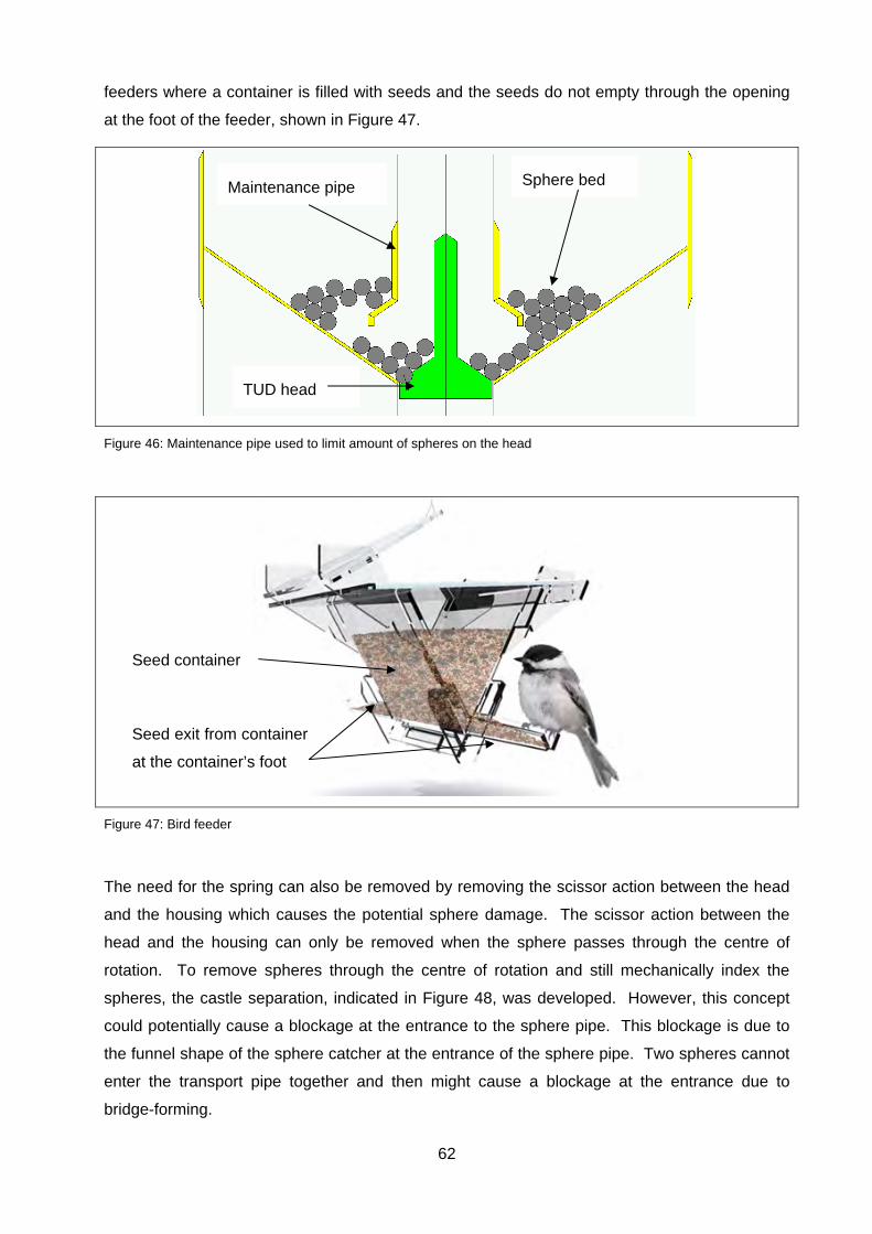
62
feeders where a container is filled with seeds and the seeds do not empty through the opening
at the foot of the feeder, shown in Figure 47.
Figure 46: Maintenance pipe used to limit amount of spheres on the head
Figure 47: Bird feeder
The need for the spring can also be removed by removing the scissor action between the head
and the housing which causes the potential sphere damage. The scissor action between the
head and the housing can only be removed when the sphere passes through the centre of
rotation. To remove spheres through the centre of rotation and still mechanically index the
spheres, the castle separation, indicated in Figure 48, was developed. However, this concept
could potentially cause a blockage at the entrance to the sphere pipe. This blockage is due to
the funnel shape of the sphere catcher at the entrance of the sphere pipe. Two spheres cannot
enter the transport pipe together and then might cause a blockage at the entrance due to
bridge-forming.
Maintenance pipe Sphere bed
TUD head
Seed container
Seed exit from container
at the container’s foot
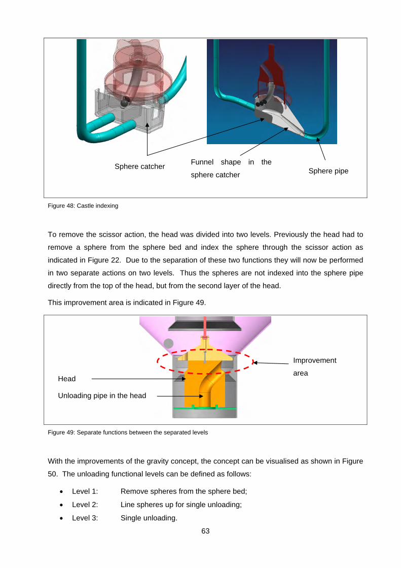
63
Figure 48: Castle indexing
To remove the scissor action, the head was divided into two levels. Previously the head had to
remove a sphere from the sphere bed and index the sphere through the scissor action as
indicated in Figure 22. Due to the separation of these two functions they will now be performed
in two separate actions on two levels. Thus the spheres are not indexed into the sphere pipe
directly from the top of the head, but from the second layer of the head.
This improvement area is indicated in Figure 49.
Figure 49: Separate functions between the separated levels
With the improvements of the gravity concept, the concept can be visualised as shown in Figure
50. The unloading functional levels can be defined as follows:
Level 1: Remove spheres from the sphere bed;
Level 2: Line spheres up for single unloading;
Level 3: Single unloading.
Sphere catcher Funnel shape in the
sphere catcher Sphere pipe
Improvement
area Head
Unloading pipe in the head
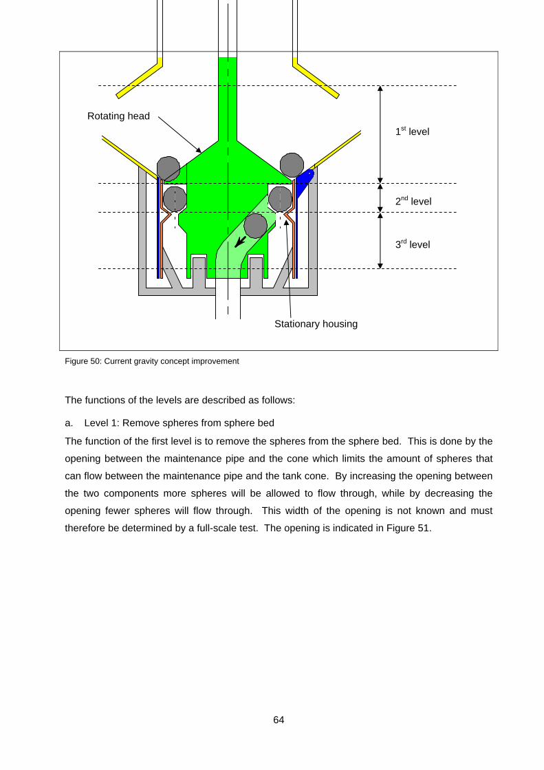
64
Figure 50: Current gravity concept improvement
The functions of the levels are described as follows:
a. Level 1: Remove spheres from sphere bed
The function of the first level is to remove the spheres from the sphere bed. This is done by the
opening between the maintenance pipe and the cone which limits the amount of spheres that
can flow between the maintenance pipe and the tank cone. By increasing the opening between
the two components more spheres will be allowed to flow through, while by decreasing the
opening fewer spheres will flow through. This width of the opening is not known and must
therefore be determined by a full-scale test. The opening is indicated in Figure 51.
2nd level
1st level
3rd level
Rotating head
Stationary housing
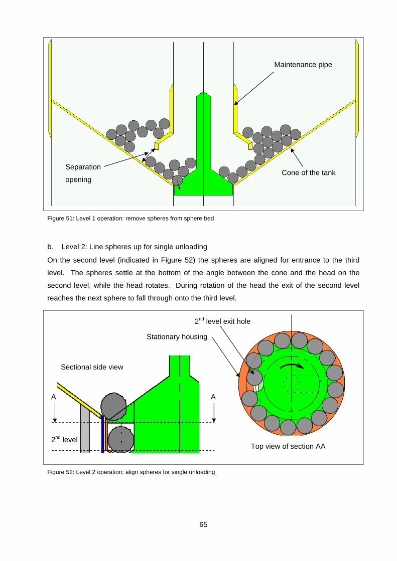
65
Figure 51: Level 1 operation: remove spheres from sphere bed
b. Level 2: Line spheres up for single unloading
On the second level (indicated in Figure 52) the spheres are aligned for entrance to the third
level. The spheres settle at the bottom of the angle between the cone and the head on the
second level, while the head rotates. During rotation of the head the exit of the second level
reaches the next sphere to fall through onto the third level.
Figure 52: Level 2 operation: align spheres for single unloading
Separation
opening Cone of the tank
Maintenance pipe
Top view of section AA
Sectional side view
A A
2nd level
2nd level exit hole
Stationary housing
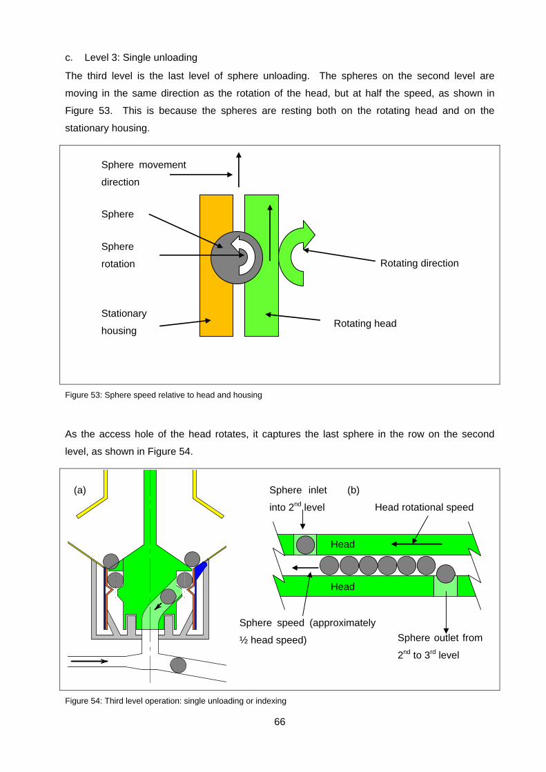
66
c. Level 3: Single unloading
The third level is the last level of sphere unloading. The spheres on the second level are
moving in the same direction as the rotation of the head, but at half the speed, as shown in
Figure 53. This is because the spheres are resting both on the rotating head and on the
stationary housing.
Figure 53: Sphere speed relative to head and housing
As the access hole of the head rotates, it captures the last sphere in the row on the second
level, as shown in Figure 54.
Figure 54: Third level operation: single unloading or indexing
Stationary
housing Rotating head
Rotating direction
Sphere
rotation
Sphere
Sphere movement
direction
Head
Head
Head rotational speed
Sphere speed (approximately
½ head speed)
Sphere inlet
into 2nd level
Sphere outlet from
2nd to 3rd level
(a) (b)
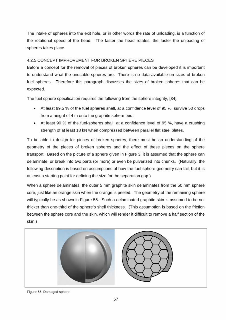
67
The intake of spheres into the exit hole, or in other words the rate of unloading, is a function of
the rotational speed of the head. The faster the head rotates, the faster the unloading of
spheres takes place.
4.2.5 CONCEPT IMPROVEMENT FOR BROKEN SPHERE PIECES
Before a concept for the removal of pieces of broken spheres can be developed it is important
to understand what the unusable spheres are. There is no data available on sizes of broken
fuel spheres. Therefore this paragraph discusses the sizes of broken spheres that can be
expected.
The fuel sphere specification requires the following from the sphere integrity, [34]:
At least 99.5 % of the fuel spheres shall, at a confidence level of 95 %, survive 50 drops
from a height of 4 m onto the graphite sphere bed;
At least 90 % of the fuel-spheres shall, at a confidence level of 95 %, have a crushing
strength of at least 18 kN when compressed between parallel flat steel plates.
To be able to design for pieces of broken spheres, there must be an understanding of the
geometry of the pieces of broken spheres and the effect of these pieces on the sphere
transport. Based on the picture of a sphere given in Figure 3, it is assumed that the sphere can
delaminate, or break into two parts (or more) or even be pulverized into chunks. (Naturally, the
following description is based on assumptions of how the fuel sphere geometry can fail, but it is
at least a starting point for defining the size for the separation gap.)
When a sphere delaminates, the outer 5 mm graphite skin delaminates from the 50 mm sphere
core, just like an orange skin when the orange is peeled. The geometry of the remaining sphere
will typically be as shown in Figure 55. Such a delaminated graphite skin is assumed to be not
thicker than one-third of the sphere’s shell thickness. (This assumption is based on the friction
between the sphere core and the skin, which will render it difficult to remove a half section of the
skin.)
Figure 55: Damaged sphere
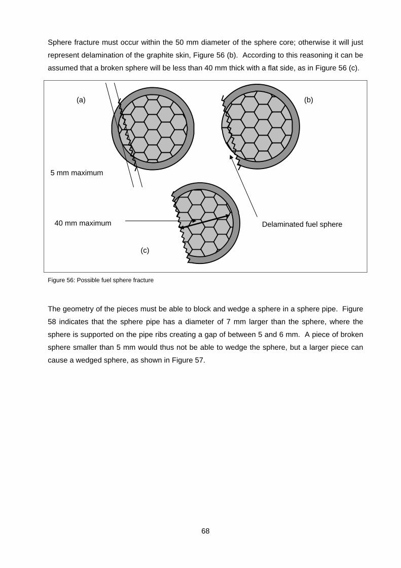
68
Sphere fracture must occur within the 50 mm diameter of the sphere core; otherwise it will just
represent delamination of the graphite skin, Figure 56 (b). According to this reasoning it can be
assumed that a broken sphere will be less than 40 mm thick with a flat side, as in Figure 56 (c).
Figure 56: Possible fuel sphere fracture
The geometry of the pieces must be able to block and wedge a sphere in a sphere pipe. Figure
58 indicates that the sphere pipe has a diameter of 7 mm larger than the sphere, where the
sphere is supported on the pipe ribs creating a gap of between 5 and 6 mm. A piece of broken
sphere smaller than 5 mm would thus not be able to wedge the sphere, but a larger piece can
cause a wedged sphere, as shown in Figure 57.
40 mm maximum Delaminated fuel sphere
5 mm maximum
(a) (b)
(c)

69
Figure 57: Sphere blockage in sphere pipe
Figure 58: Sphere pipe dimensions
Pieces of broken spheres will be transported with the spheres when they are large enough.
Based on Figure 56 it is assumed that a sphere of 50 mm, (Figure 56 (b)), can still roll in a
sphere-pipe, but a sphere of 40 mm, on a flat side, (Figure 56(c)), will not be able to roll in a
sphere pipe without transportation gas.
Figure 59 (a) and (b) indicate that a broken sphere piece must have an edge of less than 6 mm
to be able to wedge between the sphere and the sphere pipe. Figure 59 (c) shows a piece of a
sphere that is too large to wedge the sphere, and in this case the piece of sphere will be
transported with the sphere.
Sphere and broken sphere
wedged to block pipe
Sphere pipe
Broken sphere velocity
Sphere velocity
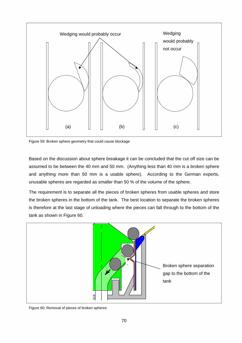
70
Figure 59: Broken sphere geometry that could cause blockage
Based on the discussion about sphere breakage it can be concluded that the cut off size can be
assumed to be between the 40 mm and 50 mm. (Anything less than 40 mm is a broken sphere
and anything more than 50 mm is a usable sphere). According to the German experts,
unusable spheres are regarded as smaller than 50 % of the volume of the sphere.
The requirement is to separate all the pieces of broken spheres from usable spheres and store
the broken spheres in the bottom of the tank. The best location to separate the broken spheres
is therefore at the last stage of unloading where the pieces can fall through to the bottom of the
tank as shown in Figure 60.
Figure 60: Removal of pieces of broken spheres
Wedging would probably occur Wedging
would probably
not occur
Broken sphere separation
gap to the bottom of the
tank
(a) (b) (c)

71
Movement restriction must be provided to support the head against horizontal movement when
larger pieces from damaged spheres are wedged through the separating opening. The
movement restriction must also comply with maintenance requirements in the nuclear industry.
Therefore it has been decided to use Vespel as the material for a bearing. Figure 61 shows
how the bearing will be installed.
Figure 61: Bearing support
The gravity concept can be re-evaluated to verify the design status against the requirements.
Table 18 indicates that the requirements have been achieved theoretically, but are to be verified
through tests.
Table 18: Re-evaluating the concept status
Criteria Advantage Disadvantage
Sphere removal from sphere bed
333 spheres / hr To be tested
Unload rhythm Theoretically every 7 seconds To be tested
Sphere damage No sphere damage foreseen
Broken sphere separation Broke sphere separation is theoretically possible To be tested
Maintenance need Measure the torque on actuator. If the torque increases there could be possible bearing damage.
Maintenance possible Yes, head can be removed
Dust generation Dust generation is limited due to slow rotation speed
Nuclear safety No sphere damage foreseen
Contact points for horizontal support
Limited
horizontal
movement

72
4.3 CONCLUSION
It can be concluded that the gravity concept complies theoretically with the requirements that
are placed on the tank unloading device. The bending stress of the metal spring assembly is
very high and will fail due to metal fatigue. In the case of the silicone spring, the life expectancy
of the silicone is not long enough to cover the required life expectancy of the unloading
machine. Thus, although calculations indicate that both the springs could work, a maintenance
plan is to be provided to prevent spring failure.
The latest improvements present a better solution for the gravity concept, not needing an
intensive maintenance plan due to the absence of the springs.

73
5. TESTING
5.1 INTRODUCTION
An examination of Table 18 confirms that the requirements have theoretically been complied
with. This section describes the testing of the gravity unloading machine developed for the tank
unloading device.
5.2 TEST METHODOLOGY
A full scale test unit was built to confirm the geometrical assumptions and to verify the TUD’s
capability to satisfactorily perform the functions that were allocated to the TUD. The functions
are as follows:
Make provision for maintenance;
Lift single sphere;
Count spheres that pass through the unit;
Separate pieces of broken spheres;
Empty tank for final decommissioning.
Geometry that has to be confirmed:
TUD maintenance pipe height;
Angle of cone ring.
Figure 62 shows the three-dimensional model of the tank unloading device test unit, which has
been designed as a full-scale model. The tank unloading device is connected to a full-scale
model of the bottom section of the storage tank in order to simulate the sphere flow though the
tank into the tank unloading device. The maintenance pipe is adjustable because the optimum
height for the opening for spheres to flow through onto the tank unloading device head (Figure
51) is to be determined through testing. For this test unit the spheres are returned to the same
tank to be able to run a continuous test.
The tests can be divided into two sets. The first set of tests is required to complete the design
(i.e. parameters that must be verified with tested settings). The second set of tests is to verify
the performance of the tank unloading device.
The first test is to verify the capability of the tank unloading device to unload a sphere and then
a string of spheres. This test will confirm the functional operation of unloading.
The second test is to determine the exact position (height) of the maintenance pipe. When the
test unit adjustment is complete, the test unit is to be filled with more spheres which will enable
to run the test continuously.
The rotating speed must be increased and decreased to determine the minimum, maximum and
optimum unloading speeds.
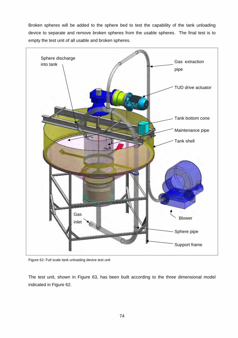
74
Broken spheres will be added to the sphere bed to test the capability of the tank unloading
device to separate and remove broken spheres from the usable spheres. The final test is to
empty the test unit of all usable and broken spheres.
Figure 62: Full scale tank unloading device test unit
The test unit, shown in Figure 63, has been built according to the three dimensional model
indicated in Figure 62.
Tank shell
Maintenance pipe
Tank bottom cone
TUD drive actuator
Sphere pipe
Support frame
Blower
Sphere discharge into tank
Gas extraction
pipe
Gas
inlet
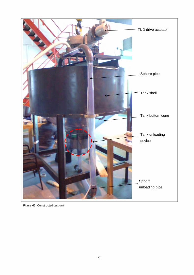
75
Figure 63: Constructed test unit
Sphere pipe
TUD drive actuator
Tank unloading
device
Tank bottom cone
Sphere
unloading pipe
Tank shell
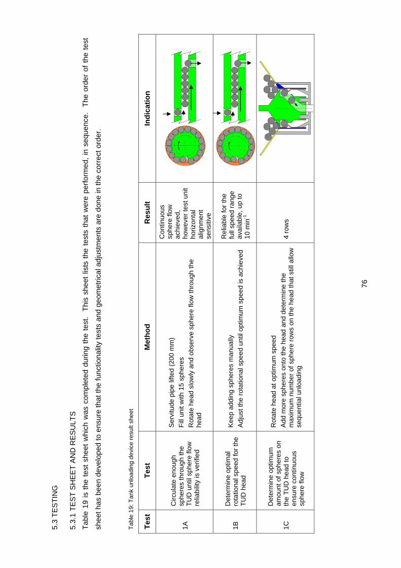
76
5.3
TE
ST
ING
5.3.
1 T
ES
T S
HE
ET
AN
D R
ES
ULT
S
Tab
le 1
9 is
the
tes
t sh
eet
whi
ch w
as c
ompl
eted
dur
ing
the
test
. T
his
shee
t lis
ts t
he t
ests
tha
t w
ere
perf
orm
ed,
in s
eque
nce.
T
he o
rder
of
the
test
shee
t has
bee
n de
velo
ped
to e
nsur
e th
at th
e fu
nctio
nalit
y te
sts
and
geom
etric
al a
djus
tmen
ts a
re d
one
in th
e co
rrec
t ord
er.
Tab
le 1
9: T
ank
unlo
adin
g d
evic
e re
sult
she
et
Tes
t T
est
M
eth
od
R
esu
lt
Ind
icat
ion
1A
Circ
ulat
e en
ough
sp
here
s th
roug
h th
e T
UD
unt
il sp
here
flow
re
liabi
lity
is v
erifi
ed
Ser
vitu
de p
ipe
lifte
d (2
00 m
m)
Fill
uni
t with
15
sphe
res
Rot
ate
head
slo
wly
and
obs
erve
sph
ere
flow
thro
ugh
the
head
Con
tinuo
us
sphe
re fl
ow
achi
eved
, ho
wev
er te
st u
nit
horiz
onta
l al
ignm
ent
sens
itive
1B
Det
erm
ine
optim
al
rota
tiona
l spe
ed fo
r th
e T
UD
hea
d
Kee
p ad
ding
sph
eres
man
ually
Adj
ust t
he r
otat
iona
l spe
ed u
ntil
optim
um s
peed
is a
chie
ved
Rel
iabl
e fo
r th
e fu
ll sp
eed
rang
e av
aila
ble,
up
to
10 m
in-1
1C
Det
erm
ine
optim
um
amou
nt o
f sph
eres
on
the
TU
D h
ead
to
ensu
re c
ontin
uous
sp
here
flow
Rot
ate
head
at o
ptim
um s
peed
Add
mor
e sp
here
s on
to th
e he
ad a
nd d
eter
min
e th
e m
axim
um n
umbe
r of
sph
ere
row
s on
the
head
that
stil
l allo
w
sequ
entia
l unl
oadi
ng
4 ro
ws

77
Tes
t T
est
M
eth
od
R
esu
lt
Ind
icat
ion
2 D
eter
min
e op
timum
fe
ed th
roug
h op
enin
g
Adj
ust s
ervi
tude
pip
e to
allo
w a
90
mm
gap
bet
wee
n pi
pe
and
cone
Rot
ate
head
and
mon
itor
for
cont
inuo
us s
pher
e flo
w
Slo
wly
add
mor
e sp
here
s to
the
unit
Adj
ust t
he s
ervi
tude
pip
e to
ens
ure
that
the
leve
l of s
pher
es
on th
e he
ad is
lim
ited
to o
ptim
um n
umbe
r of
sph
eres
Adj
ust p
ipe
low
er if
too
man
y sp
here
s ar
e on
the
head
85 m
m
3A
Det
erm
ine
the
low
er
spee
d lim
it
With
the
test
uni
t run
ning
sm
ooth
ly, l
ower
the
rota
tiona
l sp
eed
of th
e he
ad u
ntil
the
unlo
adin
g be
com
es u
nrel
iabl
e an
d no
te th
e sp
eed
limit
Rep
eat a
gain
to e
nsur
e th
at th
e lo
wer
spe
ed li
mit
is
repe
atab
le
No
min
imum
ro
tatio
nal s
peed
3B
Det
erm
ine
the
high
er
spee
d lim
it
With
the
test
uni
t run
ning
sm
ooth
ly, i
ncre
ase
the
rota
tiona
l sp
eed
of th
e he
ad u
ntil
the
unlo
adin
g be
com
es u
nrel
iabl
e an
d no
te th
e sp
eed
limit
Rep
eat a
gain
to e
nsur
e th
at th
e hi
gher
spe
ed li
mit
is
repe
atab
le
Max
spe
ed
avai
labl
e w
as
1.4
min
-1
3C
The
oret
ical
cal
cula
tions
in
dica
ted
that
a
rota
tiona
l spe
ed o
f ap
prox
imat
ely
0.
39 m
in-1
is r
equi
red
to
unlo
ad 3
33 s
pher
es/h
r.
Ver
ify th
e ro
tatio
nal
spee
d re
quire
d to
un
load
333
sph
eres
/hr
With
the
test
uni
t run
ning
sm
ooth
ly, a
djus
t the
rot
atin
g sp
eed
of th
e un
load
ing
head
unt
il th
e re
quire
d 33
3 sp
here
s/hr
is
reac
hed
Rep
eat t
he te
st to
ens
ure
repe
atab
ility
of u
nloa
ding
at t
his
spee
d
At t
his
stag
e th
e te
st s
et-u
p sh
ould
be
adju
sted
for
oper
atio
n w
ithou
t pie
ces
of b
roke
n sp
here
s
App
roxi
mat
ely
0.3
min
-1
Fee
d th
roug
h
open
ing
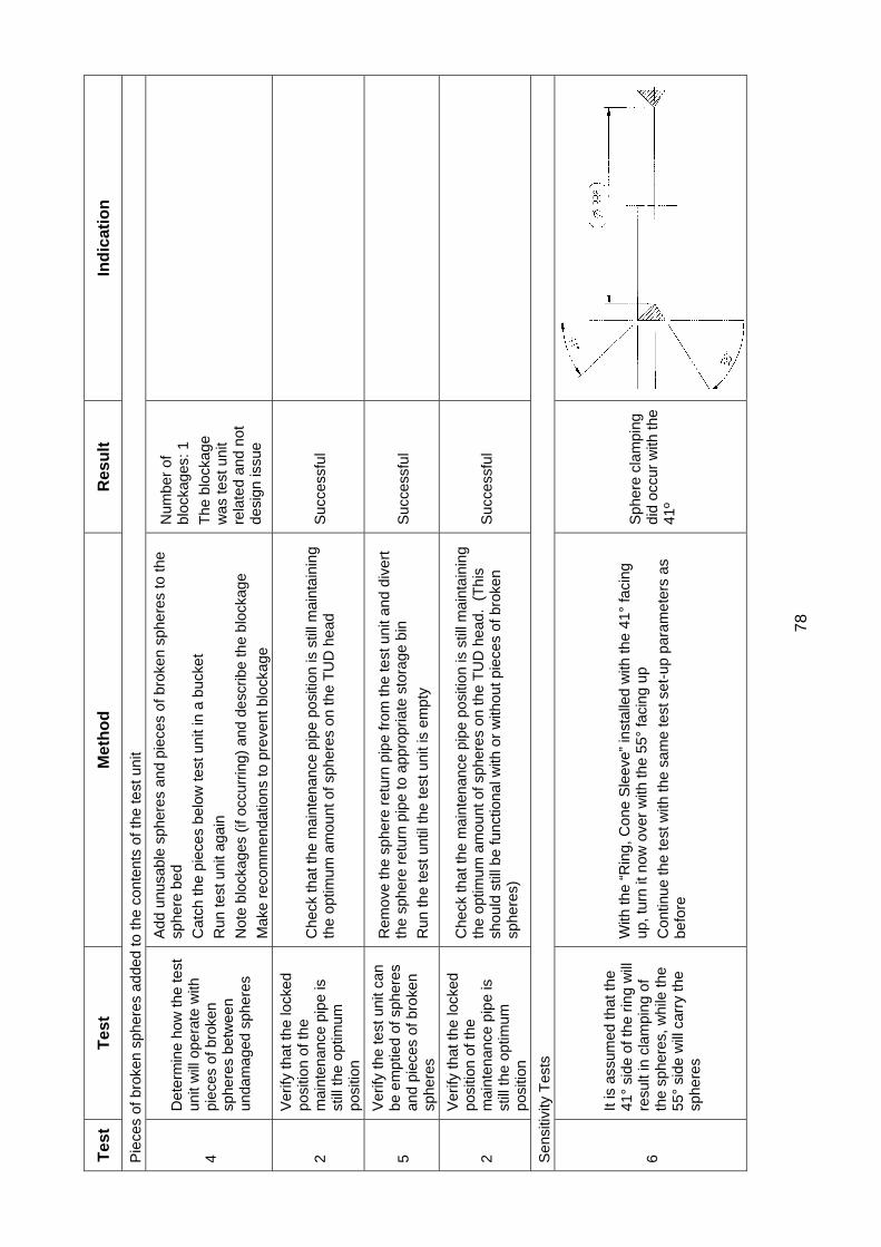
78
Tes
t T
est
M
eth
od
R
esu
lt
Ind
icat
ion
Pie
ces
of b
roke
n sp
here
s ad
ded
to th
e co
nten
ts o
f the
test
uni
t
4
Det
erm
ine
how
the
test
un
it w
ill o
pera
te w
ith
piec
es o
f bro
ken
sphe
res
betw
een
unda
mag
ed s
pher
es
Add
unu
sabl
e sp
here
s an
d pi
eces
of b
roke
n sp
here
s to
the
sphe
re b
ed
Cat
ch th
e pi
eces
bel
ow te
st u
nit i
n a
buck
et
Run
test
uni
t aga
in
Not
e bl
ocka
ges
(if o
ccur
ring)
and
des
crib
e th
e bl
ocka
ge
Mak
e re
com
men
datio
ns to
pre
vent
blo
ckag
e
Num
ber
of
bloc
kage
s: 1
The
blo
ckag
e w
as te
st u
nit
rela
ted
and
not
desi
gn is
sue
2
Ver
ify th
at th
e lo
cked
po
sitio
n of
the
mai
nten
ance
pip
e is
st
ill th
e op
timum
po
sitio
n
Che
ck th
at th
e m
aint
enan
ce p
ipe
posi
tion
is s
till m
aint
aini
ng
the
optim
um a
mou
nt o
f sph
eres
on
the
TU
D h
ead
Suc
cess
ful
5
Ver
ify th
e te
st u
nit c
an
be e
mpt
ied
of s
pher
es
and
piec
es o
f bro
ken
sphe
res
Rem
ove
the
sphe
re r
etur
n pi
pe fr
om th
e te
st u
nit a
nd d
iver
t th
e sp
here
ret
urn
pipe
to a
ppro
pria
te s
tora
ge b
in
Run
the
test
unt
il th
e te
st u
nit i
s em
pty
Suc
cess
ful
2
Ver
ify th
at th
e lo
cked
po
sitio
n of
the
mai
nten
ance
pip
e is
st
ill th
e op
timum
po
sitio
n
Che
ck th
at th
e m
aint
enan
ce p
ipe
posi
tion
is s
till m
aint
aini
ng
the
optim
um a
mou
nt o
f sph
eres
on
the
TU
D h
ead.
(T
his
shou
ld s
till b
e fu
nctio
nal w
ith o
r w
ithou
t pie
ces
of b
roke
n sp
here
s)
Suc
cess
ful
Sen
sitiv
ity T
ests
6
It is
ass
umed
that
the
41°
side
of t
he r
ing
will
re
sult
in c
lam
ping
of
the
sphe
res,
whi
le th
e 55
° si
de w
ill c
arry
the
sphe
res
With
the
“Rin
g, C
one
Sle
eve”
inst
alle
d w
ith th
e 41
° fa
cing
up
, tur
n it
now
ove
r w
ith th
e 55
° fa
cing
up
Con
tinue
the
test
with
the
sam
e te
st s
et-u
p pa
ram
eter
s as
be
fore
Sph
ere
clam
ping
di
d oc
cur
with
the
41º
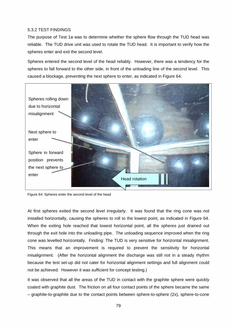
79
5.3.2 TEST FINDINGS
The purpose of Test 1a was to determine whether the sphere flow through the TUD head was
reliable. The TUD drive unit was used to rotate the TUD head. It is important to verify how the
spheres enter and exit the second level.
Spheres entered the second level of the head reliably. However, there was a tendency for the
spheres to fall forward to the other side, in front of the unloading line of the second level. This
caused a blockage, preventing the next sphere to enter, as indicated in Figure 64.
Figure 64: Spheres enter the second level of the head
At first spheres exited the second level irregularly. It was found that the ring cone was not
installed horizontally, causing the spheres to roll to the lowest point, as indicated in Figure 64.
When the exiting hole reached that lowest horizontal point, all the spheres just drained out
through the exit hole into the unloading pipe. The unloading sequence improved when the ring
cone was levelled horizontally. Finding: The TUD is very sensitive for horizontal misalignment.
This means that an improvement is required to prevent the sensitivity for horizontal
misalignment. (After the horizontal alignment the discharge was still not in a steady rhythm
because the test set-up did not cater for horizontal alignment settings and full alignment could
not be achieved. However it was sufficient for concept testing.)
It was observed that all the areas of the TUD in contact with the graphite sphere were quickly
coated with graphite dust. The friction on all four contact points of the sphere became the same
– graphite-to-graphite due to the contact points between sphere-to-sphere (2x), sphere-to-cone
Head rotation
Next sphere to
enter
Sphere in forward
position prevents
the next sphere to
enter
Spheres rolling down
due to horizontal
misalignment
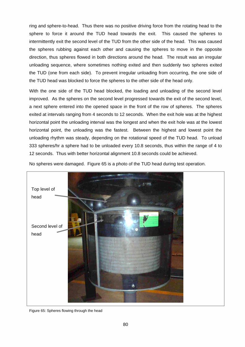
80
ring and sphere-to-head. Thus there was no positive driving force from the rotating head to the
sphere to force it around the TUD head towards the exit. This caused the spheres to
intermittently exit the second level of the TUD from the other side of the head. This was caused
the spheres rubbing against each other and causing the spheres to move in the opposite
direction, thus spheres flowed in both directions around the head. The result was an irregular
unloading sequence, where sometimes nothing exited and then suddenly two spheres exited
the TUD (one from each side). To prevent irregular unloading from occurring, the one side of
the TUD head was blocked to force the spheres to the other side of the head only.
With the one side of the TUD head blocked, the loading and unloading of the second level
improved. As the spheres on the second level progressed towards the exit of the second level,
a next sphere entered into the opened space in the front of the row of spheres. The spheres
exited at intervals ranging from 4 seconds to 12 seconds. When the exit hole was at the highest
horizontal point the unloading interval was the longest and when the exit hole was at the lowest
horizontal point, the unloading was the fastest. Between the highest and lowest point the
unloading rhythm was steady, depending on the rotational speed of the TUD head. To unload
333 spheres/hr a sphere had to be unloaded every 10.8 seconds, thus within the range of 4 to
12 seconds. Thus with better horizontal alignment 10.8 seconds could be achieved.
No spheres were damaged. Figure 65 is a photo of the TUD head during test operation.
Figure 65: Spheres flowing through the head
Top level of
head
Second level of
head
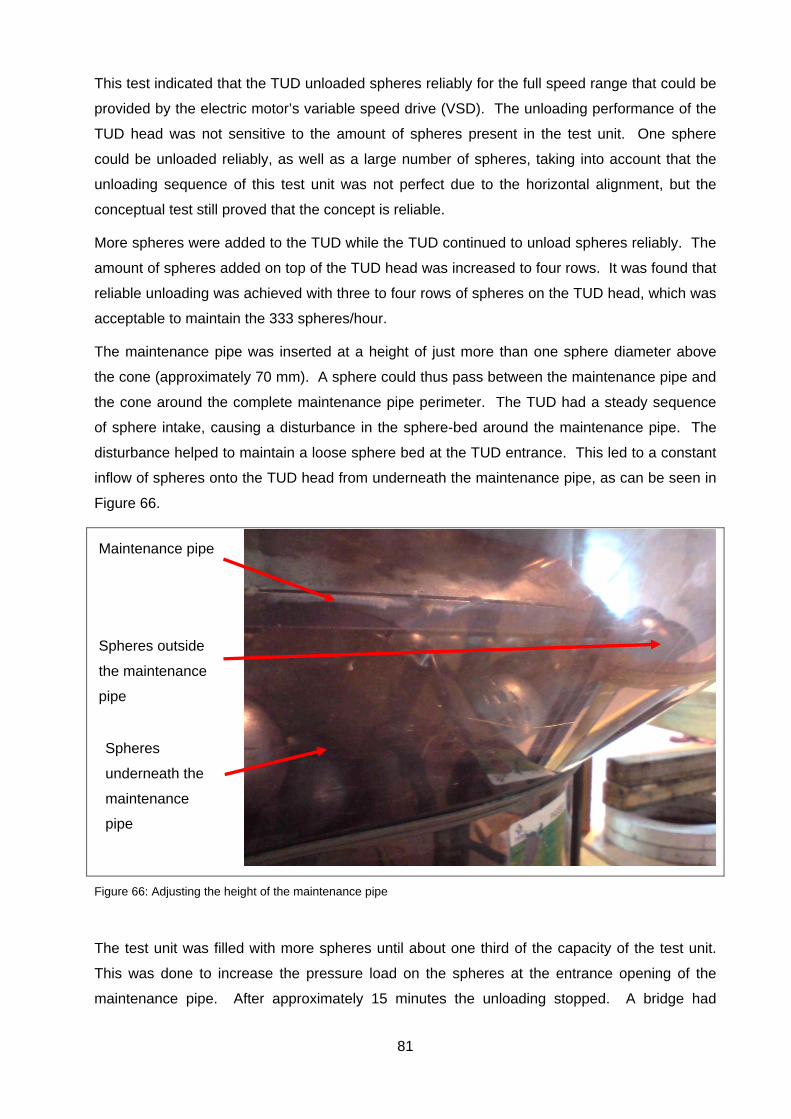
81
This test indicated that the TUD unloaded spheres reliably for the full speed range that could be
provided by the electric motor’s variable speed drive (VSD). The unloading performance of the
TUD head was not sensitive to the amount of spheres present in the test unit. One sphere
could be unloaded reliably, as well as a large number of spheres, taking into account that the
unloading sequence of this test unit was not perfect due to the horizontal alignment, but the
conceptual test still proved that the concept is reliable.
More spheres were added to the TUD while the TUD continued to unload spheres reliably. The
amount of spheres added on top of the TUD head was increased to four rows. It was found that
reliable unloading was achieved with three to four rows of spheres on the TUD head, which was
acceptable to maintain the 333 spheres/hour.
The maintenance pipe was inserted at a height of just more than one sphere diameter above
the cone (approximately 70 mm). A sphere could thus pass between the maintenance pipe and
the cone around the complete maintenance pipe perimeter. The TUD had a steady sequence
of sphere intake, causing a disturbance in the sphere-bed around the maintenance pipe. The
disturbance helped to maintain a loose sphere bed at the TUD entrance. This led to a constant
inflow of spheres onto the TUD head from underneath the maintenance pipe, as can be seen in
Figure 66.
Figure 66: Adjusting the height of the maintenance pipe
The test unit was filled with more spheres until about one third of the capacity of the test unit.
This was done to increase the pressure load on the spheres at the entrance opening of the
maintenance pipe. After approximately 15 minutes the unloading stopped. A bridge had
Spheres
underneath the
maintenance
pipe
Maintenance pipe
Spheres outside
the maintenance
pipe
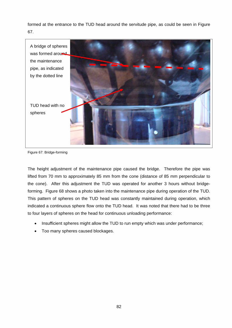
82
formed at the entrance to the TUD head around the servitude pipe, as could be seen in Figure
67.
Figure 67: Bridge-forming
The height adjustment of the maintenance pipe caused the bridge. Therefore the pipe was
lifted from 70 mm to approximately 85 mm from the cone (distance of 85 mm perpendicular to
the cone). After this adjustment the TUD was operated for another 3 hours without bridge-
forming. Figure 68 shows a photo taken into the maintenance pipe during operation of the TUD.
This pattern of spheres on the TUD head was constantly maintained during operation, which
indicated a continuous sphere flow onto the TUD head. It was noted that there had to be three
to four layers of spheres on the head for continuous unloading performance:
Insufficient spheres might allow the TUD to run empty which was under performance;
Too many spheres caused blockages.
A bridge of spheres
was formed around
the maintenance
pipe, as indicated
by the dotted line
TUD head with no
spheres

83
Figure 68: View down the maintenance pipe to TUD head loaded with spheres
Because of the sensitivity of the TUD to its horizontal alignment, the TUD performed better at
lower rotational speeds. When the head was rotating slowly, the string of spheres tended not to
roll horizontally down towards the exit hole on the second level when the exit was at its lowest
horizontal point. However, spheres could still roll down towards the exit and exit at a 4 second
interval. Refer to Table 20 for results.
The rotational speed of the TUD head was increased to the maximum allowed by the VSD,
approximately 10 min-1. Taking the horizontal misalignment into account, unloading did achieve
the 333 spheres per hour, although not at sequentially spaced intervals. The TUD head could
thus be rotated at 10 min-1 without risking damage the TUD head mechanism or the spheres.
Refer to Table 20 for results.
With the TUD being affected by horizontal alignment it was difficult to set the unloading speed
exactly. However, by counting the spheres per minute the speed could be adjusted until
approximately 334 spheres were unloaded per minute. Table 20 lists the experimental amount
of spheres unloaded against the TUD rotational speed. These values were a bit lower (amount
of spheres against revolutions per minute) than predicted. This was due to the spheres
bumping into each other as they moved around the TUD head on the second level, causing
slower sphere feed on the second level.
TUD head loaded
with spheres
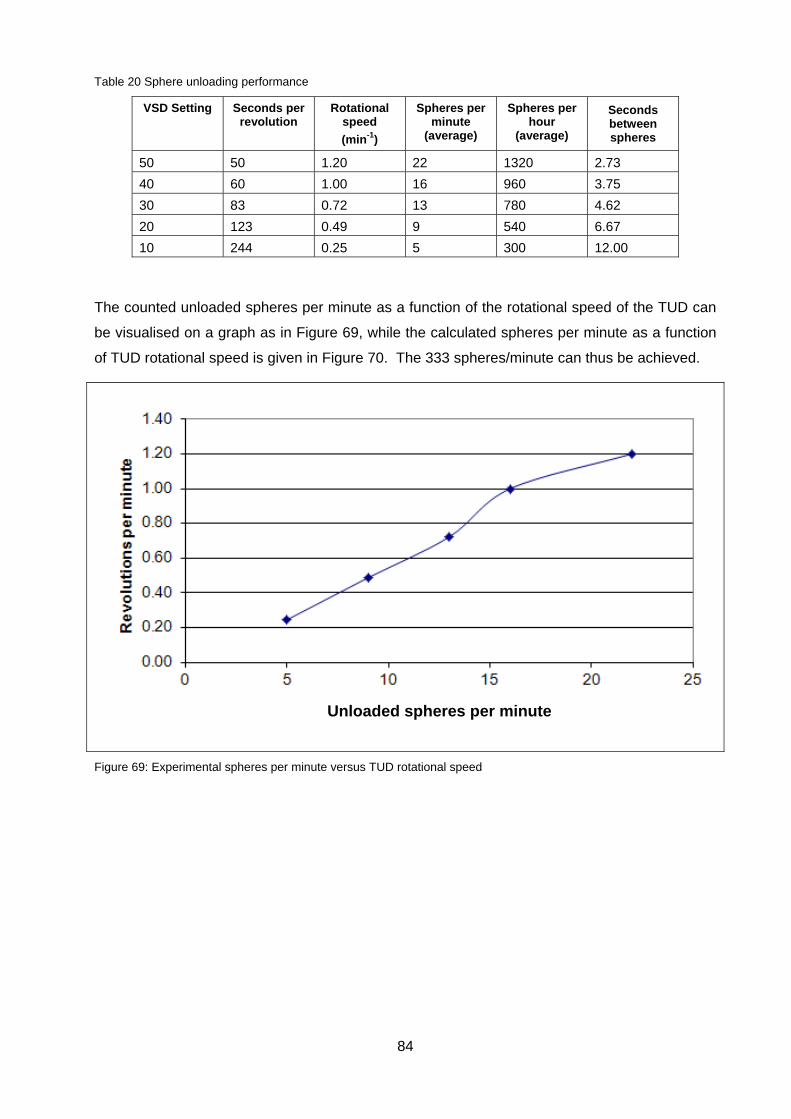
84
Table 20 Sphere unloading performance
VSD Setting Seconds per revolution
Rotational speed
(min-1)
Spheres per minute
(average)
Spheres per hour
(average)
Seconds between spheres
50 50 1.20 22 1320 2.73
40 60 1.00 16 960 3.75
30 83 0.72 13 780 4.62
20 123 0.49 9 540 6.67
10 244 0.25 5 300 12.00
The counted unloaded spheres per minute as a function of the rotational speed of the TUD can
be visualised on a graph as in Figure 69, while the calculated spheres per minute as a function
of TUD rotational speed is given in Figure 70. The 333 spheres/minute can thus be achieved.
Figure 69: Experimental spheres per minute versus TUD rotational speed
Unloaded spheres per minute
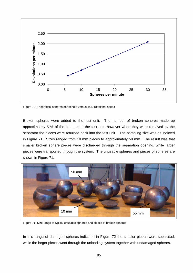
85
Figure 70: Theoretical spheres per minute versus TUD rotational speed
Broken spheres were added to the test unit. The number of broken spheres made up
approximately 5 % of the contents in the test unit, however when they were removed by the
separator the pieces were returned back into the test unit.. The sampling size was as indicted
in Figure 71. Sizes ranged from 10 mm pieces to approximately 50 mm. The result was that
smaller broken sphere pieces were discharged through the separation opening, while larger
pieces were transported through the system. The unusable spheres and pieces of spheres are
shown in Figure 71.
Figure 71: Size range of typical unusable spheres and pieces of broken spheres
In this range of damaged spheres indicated in Figure 72 the smaller pieces were separated,
while the larger pieces went through the unloading system together with undamaged spheres.
0.00
0.50
1.00
1.50
2.00
2.50
0 5 10 15 20 25 30 35
Rev
olu
tio
ns
per
min
ute
Spheres per minute
10 mm 55 mm
50 mm
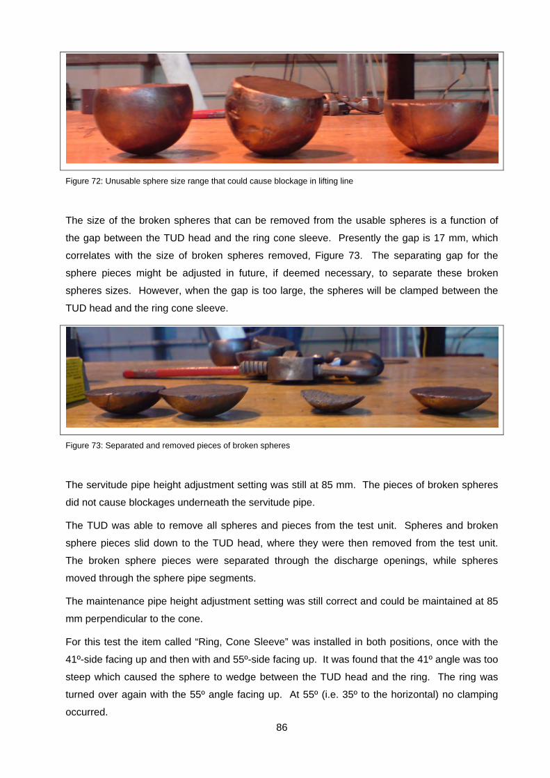
86
Figure 72: Unusable sphere size range that could cause blockage in lifting line
The size of the broken spheres that can be removed from the usable spheres is a function of
the gap between the TUD head and the ring cone sleeve. Presently the gap is 17 mm, which
correlates with the size of broken spheres removed, Figure 73. The separating gap for the
sphere pieces might be adjusted in future, if deemed necessary, to separate these broken
spheres sizes. However, when the gap is too large, the spheres will be clamped between the
TUD head and the ring cone sleeve.
Figure 73: Separated and removed pieces of broken spheres
The servitude pipe height adjustment setting was still at 85 mm. The pieces of broken spheres
did not cause blockages underneath the servitude pipe.
The TUD was able to remove all spheres and pieces from the test unit. Spheres and broken
sphere pieces slid down to the TUD head, where they were then removed from the test unit.
The broken sphere pieces were separated through the discharge openings, while spheres
moved through the sphere pipe segments.
The maintenance pipe height adjustment setting was still correct and could be maintained at 85
mm perpendicular to the cone.
For this test the item called “Ring, Cone Sleeve” was installed in both positions, once with the
41º-side facing up and then with and 55º-side facing up. It was found that the 41º angle was too
steep which caused the sphere to wedge between the TUD head and the ring. The ring was
turned over again with the 55º angle facing up. At 55º (i.e. 35º to the horizontal) no clamping
occurred.

87
5.4 CONCLUSION
The sphere geometry and sphere integrity were maintained during the unloading test, thus no
spheres were damaged by the test unit. However, the horizontal misalignment influenced the
overall performance of the TUD with regard to sequential timing between spheres. These
findings are as follows:
TUD installation requires accurate horizontal installation, (Test 1A);
The ring cone must be installed with the 55º angle on the top (resulting in 35º angle),
(Test 6).
Further improvement to the concept can be done. Figure 63 indicates humps or obstacles that
can be added to the ring cone to prevent spheres from rolling to the lowest point, thus reducing
the effect of horizontal misalignment. These humps should space the spheres on the second
level to prevent them from touching. Due to these humps, the top hole will position the sphere
in the space between the bumps and the sphere will fall into the bottom hole of the TUD head
when the hole passes by. The height of the hump should be less than the space between the
TUD head and the sphere to prevent sphere clamping between TUD head and the cone sleeve.
Figure 74: Humps proposal to limit sensitivity for horizontal misalignment
Humps provided to prevent sphere
rolling at horizontal misalignment
Sphere in
Sphere out
Head move
Spheres not
moving between
humps
Head move
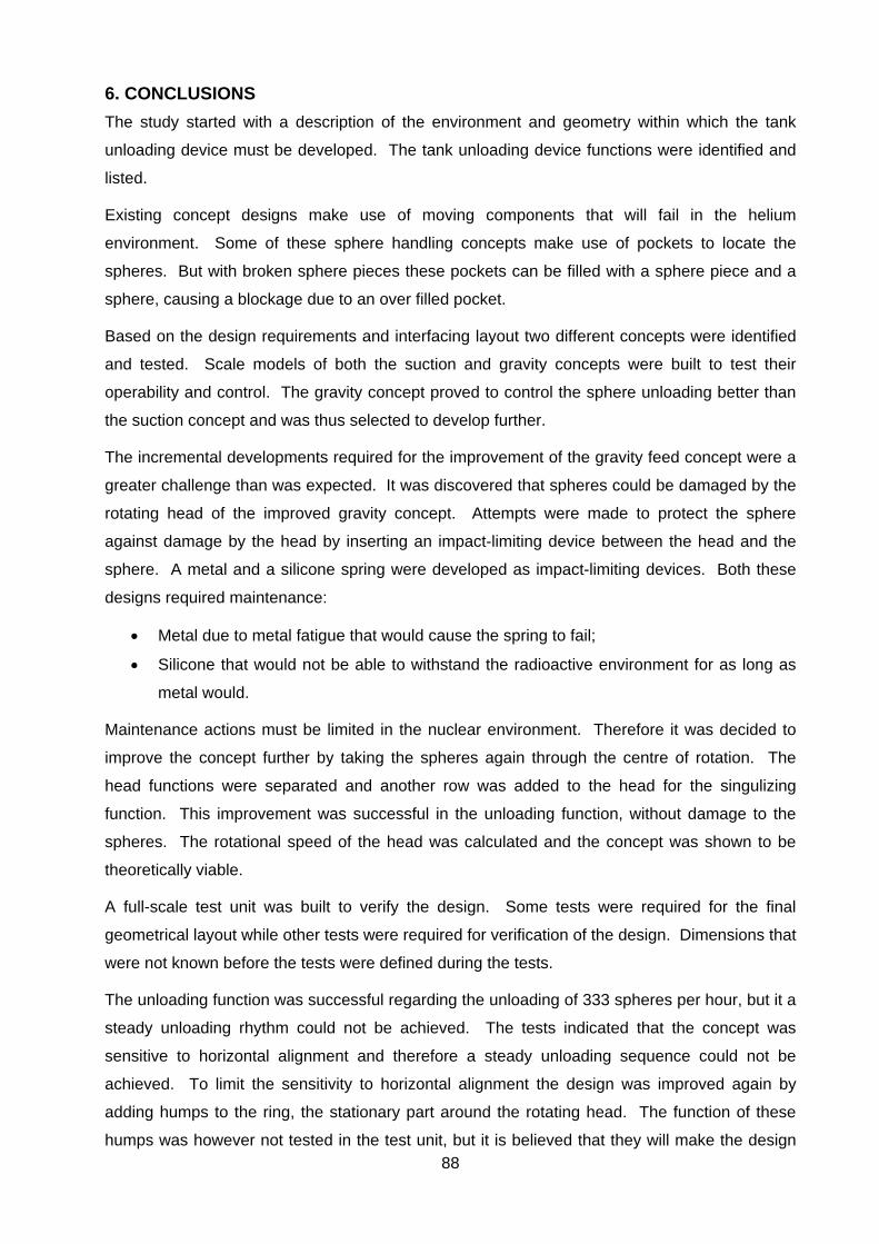
88
6. CONCLUSIONS
The study started with a description of the environment and geometry within which the tank
unloading device must be developed. The tank unloading device functions were identified and
listed.
Existing concept designs make use of moving components that will fail in the helium
environment. Some of these sphere handling concepts make use of pockets to locate the
spheres. But with broken sphere pieces these pockets can be filled with a sphere piece and a
sphere, causing a blockage due to an over filled pocket.
Based on the design requirements and interfacing layout two different concepts were identified
and tested. Scale models of both the suction and gravity concepts were built to test their
operability and control. The gravity concept proved to control the sphere unloading better than
the suction concept and was thus selected to develop further.
The incremental developments required for the improvement of the gravity feed concept were a
greater challenge than was expected. It was discovered that spheres could be damaged by the
rotating head of the improved gravity concept. Attempts were made to protect the sphere
against damage by the head by inserting an impact-limiting device between the head and the
sphere. A metal and a silicone spring were developed as impact-limiting devices. Both these
designs required maintenance:
Metal due to metal fatigue that would cause the spring to fail;
Silicone that would not be able to withstand the radioactive environment for as long as
metal would.
Maintenance actions must be limited in the nuclear environment. Therefore it was decided to
improve the concept further by taking the spheres again through the centre of rotation. The
head functions were separated and another row was added to the head for the singulizing
function. This improvement was successful in the unloading function, without damage to the
spheres. The rotational speed of the head was calculated and the concept was shown to be
theoretically viable.
A full-scale test unit was built to verify the design. Some tests were required for the final
geometrical layout while other tests were required for verification of the design. Dimensions that
were not known before the tests were defined during the tests.
The unloading function was successful regarding the unloading of 333 spheres per hour, but it a
steady unloading rhythm could not be achieved. The tests indicated that the concept was
sensitive to horizontal alignment and therefore a steady unloading sequence could not be
achieved. To limit the sensitivity to horizontal alignment the design was improved again by
adding humps to the ring, the stationary part around the rotating head. The function of these
humps was however not tested in the test unit, but it is believed that they will make the design
89
fully compliant with all the requirements, because the rhythmic unloading was the only non-
compliance.
The 85 mm distance between the cone and the maintenance pipe, measured perpendicular to
the cone, will prevent bridge forming, while preventing overfilling of spheres onto the TUD head.
This distance of 85 mm maintains three to four rows of spheres on the head which is adequate
to maintain a constant sphere unloading.
A robust design was developed and tested with a full-scale test unit for the unloading of nuclear
fuel spheres. These spheres can now be unloaded by this tank unloading device from the
storage tank without damage to the fuel spheres.
The tank unloading device has been developed with materials that can withstand the nuclear
environment. Furthermore the unloading device can operate in a graphite dust filled helium
environment. Maintenance requirements have been reduced by placing the maintenance
intensive items outside the pressure boundary. Therefore the actuator is situated outside the
helium pressure boundary. The actuator is a normal off-the-shelf item used at various places in
the plant. For the second concept no special requirements such as angle sensing or torque
limitation have been placed on the actuator.
The pressure boundary is penetrated with an item called shaft penetration, which is used in
other machinery where the helium pressure boundary is penetrated. Since this proven
technology has no effect on the unloading principle, no attention has been given in this study to
the shaft penetration.
90
7. REFERENCES
[1] Dudley T. et al., The Fuel Handling and Storage System (FHSS) Model for the Pebble
Bed Modular Reactor (PBMR) Plant Training Simulator, Proceedings of 3rd International
Topical Meeting on High Temperature Reactor Technology, Johannesburg, South Africa,
October 2006
[2] Venter P.J., Mitchell M.N., Fortier F., PBMR reactor design and development, 18th
International Conference on Structural Mechanics in Reactor Technology, Beijing, China,
August 7-12, 2005
[3] Matzner D., PBMR Existing and Future R&D Test Facilities, Proceedings of 2nd
International Topical Meeting on High Temperature Reactor Technology, Beijing, China,
September 2004
[4] Cachon L. et al., Tribology in High Temperature Helium: First Phase of the CEA Helium
Technology Program, Proceedings of 2nd International Topical Meeting on High
Temperature Reactor Technology, Beijing, China, September 2004
[5] Cogliati J.J., Ougouag A. M., Pebble bed reactor dust production model, Proceedings of
4th International Topical Meeting on High Temperature Reactor Technology, Washington,
DC USA, September 2008
[6] Li C.C., Sheehan J.E., Friction and wear studies of graphite and a carbon-carbon
composite in air and in helium, Department of Energy, October 1980
[7] Luo X., Yu S., Sheng X., He S., Graphite friction coefficient for various conditions, Institute
of Nuclear Energy Technology, Tsinghua University, Beijing, Science in China, Vol. 44
Supp., 248-252, August, 2001
[8] Liu J. G., Design and full scale test of the fuel handling system, Nuclear Engineering and
Design 218 (2002) 169-178, 2002
[9] Hong R. et al., Reactor safety and mechanical design for the Annular Pebble Bed
Advanced High Temperature Reactor, University of California, Department of Nuclear
Engineering, May 19, 2009
[10] Dong J., Yu S., Concept of pebble bed based HTGR with fast pebble discharge system,
Proceedings of 2nd International Topical Meeting on High Temperature Reactor
Technology, Beijing, China, September 2004
[11] Hrovat Dr. M., Grosse K., Manufacture of high corrosion resistant fuel spheres for high
temperature pebble bed modular reactors (PBMR), Proceedings of 3rd International
91
Topical Meeting on High Temperature Reactor Technology, Johannesburg, South Africa,
October 2006
[12] IAEA, INSAG 12, Basic Safety Principles for Nuclear Power Plants, Vienna, Austria, 1999
[13] U.S.NRC, Next Generation Nuclear Plant Phenomena Identification and Ranking Tables
(PIRTs) Volume 1: Main Report, March 2008
[14] Theymann W., Engel R., Demus H., Ceramic coatings for protection against frictional
wear and diffusion welding in HTR helium, Nuclear Engineering and Design 119 (1990)
447-457, 1990
[15] Petti D. A., et al., Key Differences in the Fabrication, Irradiation of U.S. and German Triso-
coated Particle Fuel and their Implications on Fuel Performance, Idaho Falls, Idaho,
INEEL/EXT-02-00300, June 2002
[16] IAEA, INSAG 10, Defence in Depth in Nuclear Safety, Vienna, Austria, June 1996
[17] Pipeline Engineering, Sphere unloading concept, www.pipelineengineering.com [Website
accessed on 16 June 2010]
[18] Tennis robot, Pick-up mechanism for tennis balls, http://tennisrobot.org/pick-up-
mechanism/ [Website accessed on 16 June 2010]
[19] Tippmann Pneumatics Inc, A-5 Owner’s manual CO2 powered Paintball Marker, Ford
Wayne, USA
[20] V&P Scientific, Inc., Scientific Levitation Ball Loader VP725C, Operating Instructions, San
Diego, USA
[21] Oak Ridge National Laboratory, Conceptual design of the pebble bed reactor experiment,
Oakridge, USA, May 17, 1962
[22] Tian J., Loading and unloading scheme of the ordered bed modular reactor, 3rd
International Topical Meeting on High Temperature Reactor Technology, Johannesburg,
South Africa, October 1, 2006
[23] Wacker Silicones, Elastosil brochure, www.wacker.com [Website accessed on 15 August
2010]
[24] James Walker, brochure for Shieldseal Elastomers for use with ionising radiation,
www.jameswalker.biz [Website accessed on 15 August 2010]
[25] Silicone Engineering, Cellular Silicone Elastomer, www.silicone.co.uk [Website accessed
on 15 August 2010]
[26] Rogers Corporation, www.rogerscorp.com [Website accessed on 15 August 2010]
92
[27] Dupont, Design Handbook Vespel S Line, www2.dupont.com [Website accessed on 15
August 2010]
[28] Shigley J. E., Mechanical Engineering Design, 1st Metric Edition, McGraw-Hill, New York,
1986
[29] Wolfram Mathworld, http://mathworld.wolfram.com/SpherePacking.html [Website
accessed on 25 October 2010]
[30] Harmonic Drive, Catalogue for the FHA series, www.harmonicdrive.net [Website
accessed on 25 August 2010]
[31] Leine & Linde, Catalogue for angle encoders, www.mclennan.co.uk [Website accessed on
25 August 2010]
[32] Heid Antriebstechnik, Catalogue for Electromagnetic Stationary Field Multi-Disc Clutch,
www.heid-antriebstechnik.at [Website accessed on 25 August 2010]
[33] Shelley Steels, EN24 Material properties, http://www.shelleysteels.co.uk/en24.htm
[Website accessed on 12 August 2010]
[34] PBMR Fuel Spheres, Product Specification, PB-FTP-0001, Centurion, South Africa

93
8. APPENDIX A
A 1. PURPOSE
A1.1 Purpose of this calculation recordThe purpose of this calculation record is to capture all the calculations that have been done to date on theTUD Drive Assembly and the head kinematics during operation of the TUD Drive Assembly.
A1.2 Scope of this calculation recordThe torque needed to operate the TUD at the required sphere discharge rate will be calculated as well asthe capabilities of the drive shafts. It will also be determined if a spring is required to protect the sphereagainst damage should the sphere be jammed between the head and housing. If so, the spring types andtheir sizes will be determined.
A1.3 ApplicabilityThis document is applicable to the TUD drive assembly and the TUD head.
A 2. APPLICABLE AND REFERENCE DOCUMENTATION / DATA
[1] Petti D. A., et al, Key Differences in the Fabrication, Irradiation of U.S. and GermanTriso-coated Particle Fuel and their Implications on Fuel Performance, INEEL/EXT-02-00300,June 2002
[2] Bonuskor Steel, Cataloque[3] Mechanics of Materials, ISBN 0 534-37133-7, 5th edition[4] Mechanical Engineering Design, ISBN 0-07-056898-7, 1st Metric
A 3. ASSUMPTIONS / EXCLUSIONSThe following assumptions were made:1) A height of more than 1m of spheres will not have a weight effect on the head ;2) No friction in system, except where the friction of the spheres on the head is stated;3) Head has only one exit hole.

A4. NUMENCLATUREA4.1 SYMBOLS
Angular acceleration rad/s2
Density kg/m3
Stress MPa Shear stress MPa Angular velocity rad/s Friction coefficient Poison's ratio
A Area m2
D Diameter mE Modulus of elasticity GPaF Force NI Moment of inertia
J Moment of inertia around shaft center m2 kgPf Packaging factor
S Section modulus m3
Sf Safety factorT Torque Nm
V Volume m3
W Weight Nb Breadth mk Spring stiffness kN/ml Length mm Mass kgn number of ...r Radius mt Time in seconds secv Linear velocity m/sx Distance change m
A4.2 SUBSCRIPTS Friction CoefficientL Lifea Amplitudeact Actuatorc Coil (spring)cut Value where sphere will be cute Effectivef Fatiguegr Graphitei Incrementim Impactm Meanmax Maximummin Minimummw music Wireo_ Outer of _ (something)pl Plate (spring)r Rubberse Endurance limit in shears Spheresh Shaftsp headsq Square
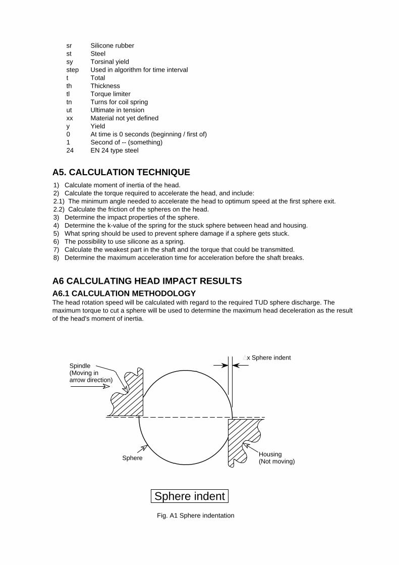
sr Silicone rubberst Steelsy Torsinal yieldstep Used in algorithm for time intervalt Totalth Thicknesstl Torque limitertn Turns for coil springut Ultimate in tensionxx Material not yet definedy Yield0 At time is 0 seconds (beginning / first of)1 Second of -- (something)24 EN 24 type steel
A5. CALCULATION TECHNIQUE1) Calculate moment of inertia of the head.2) Calculate the torque required to accelerate the head, and include:2.1) The minimum angle needed to accelerate the head to optimum speed at the first sphere exit.2.2) Calculate the friction of the spheres on the head.3) Determine the impact properties of the sphere.4) Determine the k-value of the spring for the stuck sphere between head and housing.5) What spring should be used to prevent sphere damage if a sphere gets stuck.6) The possibility to use silicone as a spring.7) Calculate the weakest part in the shaft and the torque that could be transmitted.8) Determine the maximum acceleration time for acceleration before the shaft breaks.
A6 CALCULATING HEAD IMPACT RESULTSA6.1 CALCULATION METHODOLOGYThe head rotation speed will be calculated with regard to the required TUD sphere discharge. Themaximum torque to cut a sphere will be used to determine the maximum head deceleration as the resultof the head's moment of inertia.
Sphere indent
x Sphere indent
Housing(Not moving)
Spindle(Moving inarrow direction)
Sphere
Fig. A1 Sphere indentation
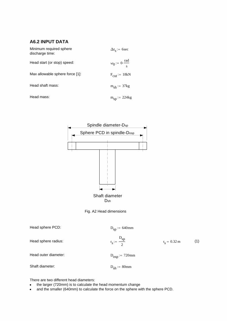
A6.2 INPUT DATA
Minimum required spheredischarge time:
Δts 6sec
Head start (or stop) speed: ω0 0rad
s
Max allowable sphere force [1]: Fcut 18kN
Head shaft mass: msh 37kg
Head mass: msp 224kg
Spindle diameter-Dsp
Sphere PCD in spindle-Dosp
Shaft diameterDsh
Fig. A2 Head dimensions
Head sphere PCD: Dsp 640mm
Head sphere radius: rs
Dsp
2 rs 0.32 m (1)
Head outer diameter: Dosp 720mm
Shaft diameter: Dsh 80mm
There are two different head diameters:the larger (720mm) is to calculate the head momentum changeand the smaller (640mm) to calculate the force on the sphere with the sphere PCD.
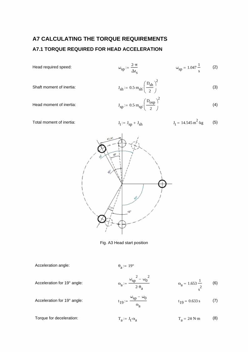
A7 CALCULATING THE TORQUE REQUIREMENTS
A7.1 TORQUE REQUIRED FOR HEAD ACCELERATION
Head required speed: ωsp2 π
Δts ωsp 1.047
1
s (2)
Shaft moment of inertia: Jsh 0.5 mshDsh
2
2
(3)
Head moment of inertia: Jsp 0.5 mspDosp
2
2
(4)
Total moment of inertia: Jt Jsp Jsh Jt 14.545 m2
kg (5)
Fig. A3 Head start position
Acceleration angle: θa 19°
Acceleration for 19° angle: αa
ωsp2
ω02
2 θa αa 1.653
1
s2
(6)
Acceleration for 19° angle: t19
ωsp ω0
αa t19 0.633 s (7)
Torque for deceleration: Ta Jt αa Ta 24 N m (8)
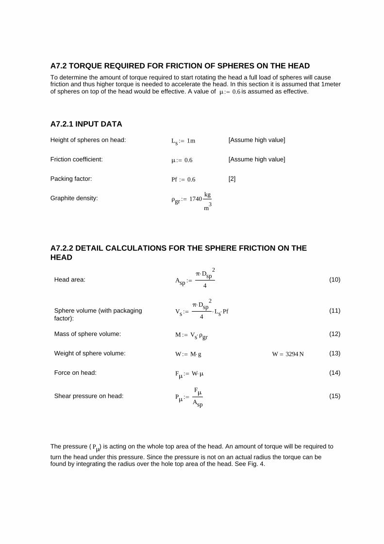
A7.2 TORQUE REQUIRED FOR FRICTION OF SPHERES ON THE HEAD
To determine the amount of torque required to start rotating the head a full load of spheres will causefriction and thus higher torque is needed to accelerate the head. In this section it is assumed that 1meterof spheres on top of the head would be effective. A value of μ 0.6 is assumed as effective.
A7.2.1 INPUT DATA
Height of spheres on head: Ls 1m [Assume high value]
Friction coefficient: μ 0.6 [Assume high value]
Packing factor: Pf 0.6 [2]
Graphite density: ρgr 1740kg
m3
A7.2.2 DETAIL CALCULATIONS FOR THE SPHERE FRICTION ON THEHEAD
Head area: Asp
π Dsp2
4 (10)
Sphere volume (with packagingfactor):
Vs
π Dsp2
4Ls Pf (11)
Mass of sphere volume: M Vs ρgr (12)
Weight of sphere volume: W M g W 3294 N (13)
Force on head: Fμ W μ (14)
Shear pressure on head: Pμ
Fμ
Asp (15)
The pressure ( Pμ) is acting on the whole top area of the head. An amount of torque will be required to
turn the head under this pressure. Since the pressure is not on an actual radius the torque can befound by integrating the radius over the hole top area of the head. See Fig. 4.
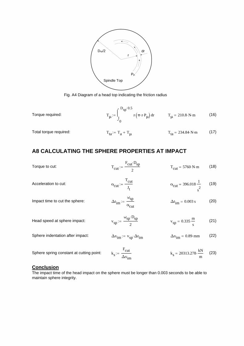
rdrDsp/2
P
Spindle Top
Fig. A4 Diagram of a head top indicating the friction radius
Torque required: Tμ0
Dsp 0.5
rr π r Pμ
d Tμ 210.8 N m (16)
Total torque required: Tta Ta Tμ Tta 234.84 N·m (17)
A8 CALCULATING THE SPHERE PROPERTIES AT IMPACT
Torque to cut: Tcut
Fcut Dsp
2 Tcut 5760 N m (18)
Acceleration to cut: αcut
Tcut
Jt αcut 396.018
1
s2
(19)
Impact time to cut the sphere: Δtim
ωsp
αcut Δtim 0.003 s (20)
Head speed at sphere impact: vsp
ωsp Dsp
2 vsp 0.335
m
s (21)
Sphere indentation after impact: Δxim vsp Δtim Δxim 0.89 mm (22)
Sphere spring constant at cutting point: ks
Fcut
Δxim ks 20313.278
kN
m (23)
ConclusionThe impact time of the head impact on the sphere must be longer than 0.003 seconds to be able tomaintain sphere integrity.
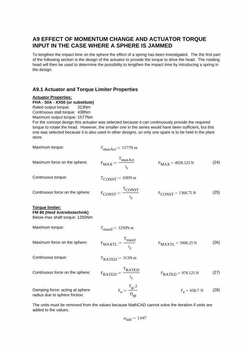
A9 EFFECT OF MOMENTUM CHANGE AND ACTUATOR TORQUEINPUT IN THE CASE WHERE A SPHERE IS JAMMED
To lengthen the impact time on the sphere the effect of a spring has been investigated. The the first partof the following section is the design of the actuator to provide the torque to drive the head. The rotatinghead will then be used to determine the possibility to lengthen the impact time by introducing a spring inthe design.
A9.1 Actuator and Torque Limiter Properties
Actuator Properties:FHA - 50A - XX50 (or substitute)Rated output torque: 313NmContinuous stall torque: 438NmMaximum output torque: 1577NmFor the concept design this actuator was selected because it can continuously provide the requiredtorque to rotate the head. However, the smaller one in the series would have been sufficient, but thisone was selected because it is also used in other designs, so only one spare is to be held in the plantstore.
Maximum torque: TmaxAct 1577N m
Maximum force on the sphere: FMAX
TmaxAct
rs FMAX 4928.125 N (24)
Continuous torque: TCONST 438N m
Continuous force on the sphere: FCONST
TCONST
rs FCONST 1368.75 N (25)
Torque limiter:FM 80 (Heid Antriebstechnik)Below max shaft torque: 1250Nm
Maximum torque: Tmaxtl 1250N m
Maximum force on the sphere: FMAXTL
Tmaxtl
rs FMAXTL 3906.25 N (26)
Continuous torque: TRATED 313N m
Continuous force on the sphere: FRATED
TRATED
rs FRATED 978.125 N (27)
Damping force: acting at sphereradius due to sphere friction.
Fe
Tμ 2
Dsp Fe 658.7 N (28)
The units must be removed from the values because MathCAD cannot solve the iteration if units areadded to the values.
ωinit 1.047
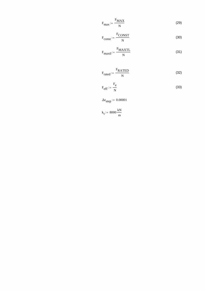
Fmax
FMAX
N (29)
Fconst
FCONST
N (30)
Fmaxtl
FMAXTL
N (31)
Frated
FRATED
N (32)
Feff
Fe
N (33)
Δtstep 0.00001
kt 8000kN
m
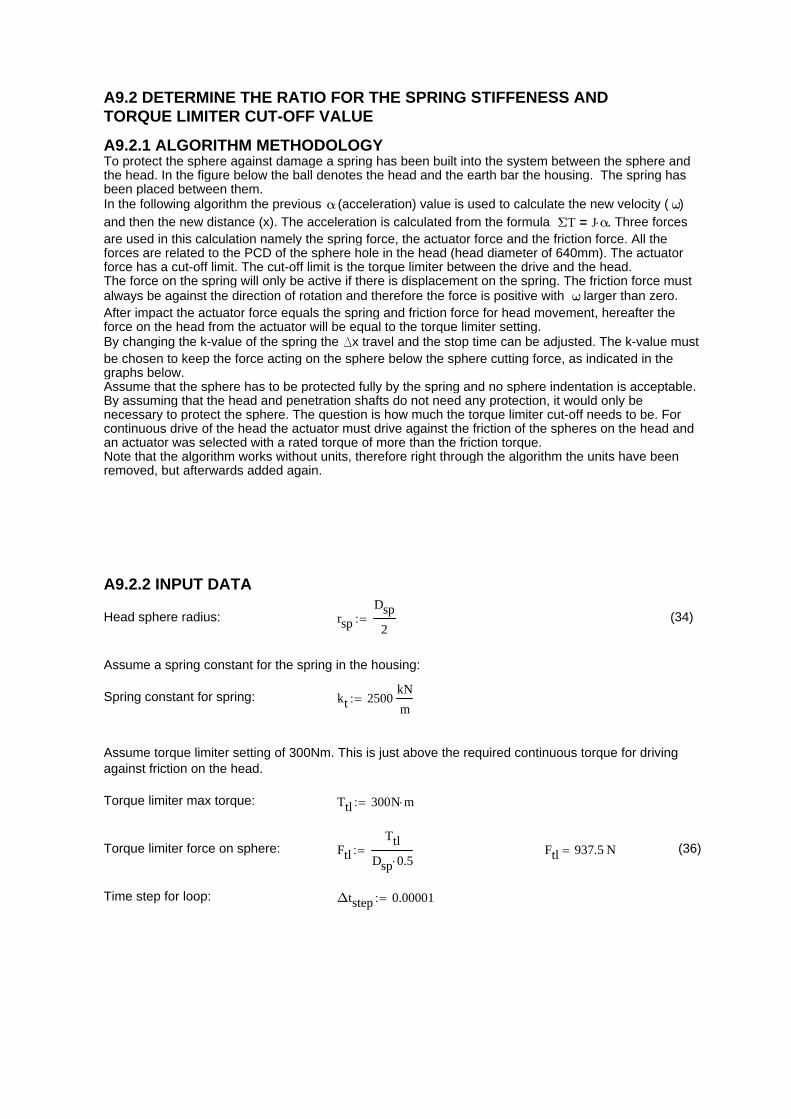
A9.2 DETERMINE THE RATIO FOR THE SPRING STIFFENESS ANDTORQUE LIMITER CUT-OFF VALUE
A9.2.1 ALGORITHM METHODOLOGYTo protect the sphere against damage a spring has been built into the system between the sphere andthe head. In the figure below the ball denotes the head and the earth bar the housing. The spring hasbeen placed between them. In the following algorithm the previous α (acceleration) value is used to calculate the new velocity ( ω)and then the new distance (x). The acceleration is calculated from the formula ΣT J α= . Three forcesare used in this calculation namely the spring force, the actuator force and the friction force. All theforces are related to the PCD of the sphere hole in the head (head diameter of 640mm). The actuatorforce has a cut-off limit. The cut-off limit is the torque limiter between the drive and the head.The force on the spring will only be active if there is displacement on the spring. The friction force mustalways be against the direction of rotation and therefore the force is positive with ω larger than zero.After impact the actuator force equals the spring and friction force for head movement, hereafter theforce on the head from the actuator will be equal to the torque limiter setting.By changing the k-value of the spring the Dx travel and the stop time can be adjusted. The k-value mustbe chosen to keep the force acting on the sphere below the sphere cutting force, as indicated in thegraphs below. Assume that the sphere has to be protected fully by the spring and no sphere indentation is acceptable.By assuming that the head and penetration shafts do not need any protection, it would only benecessary to protect the sphere. The question is how much the torque limiter cut-off needs to be. Forcontinuous drive of the head the actuator must drive against the friction of the spheres on the head andan actuator was selected with a rated torque of more than the friction torque. Note that the algorithm works without units, therefore right through the algorithm the units have beenremoved, but afterwards added again.
A9.2.2 INPUT DATA
Head sphere radius: rsp
Dsp
2 (34)
Assume a spring constant for the spring in the housing:
Spring constant for spring: kt 2500kN
m
Assume torque limiter setting of 300Nm. This is just above the required continuous torque for drivingagainst friction on the head.
Torque limiter max torque: Ttl 300N m
Torque limiter force on sphere: Ftl
Ttl
Dsp 0.5 Ftl 937.5 N (36)
Time step for loop: Δtstep 0.00001
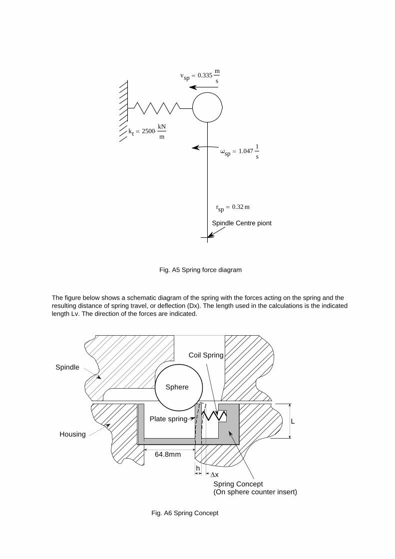
Spindle Centre piont
vsp 0.335m
s
kt 2500kN
m
ωsp 1.0471
s
rsp 0.32 m
Fig. A5 Spring force diagram
The figure below shows a schematic diagram of the spring with the forces acting on the spring and theresulting distance of spring travel, or deflection (Dx). The length used in the calculations is the indicatedlength Lv. The direction of the forces are indicated.
Sphere
Spindle
Spring Concept(On sphere counter insert)
x
64.8mm
Housing
h
L
Coil Spring
Plate spring
Fig. A6 Spring Concept
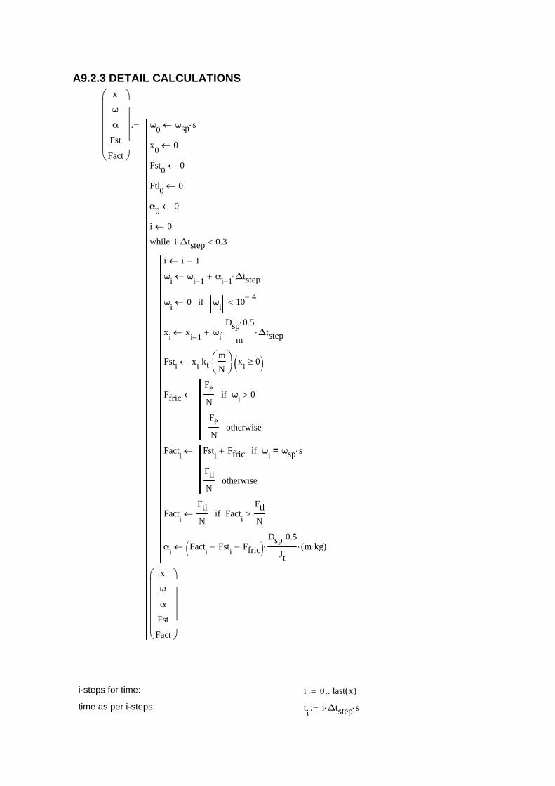
A9.2.3 DETAIL CALCULATIONSx
ω
α
Fst
Fact
ω0
ωsp s
x0
0
Fst0
0
Ftl0
0
α0
0
i 0
i i 1
ωi
ωi 1 α
i 1 Δtstep
ωi
0 ωi
104
if
xi
xi 1 ω
i
Dsp 0.5
m Δtstep
Fsti
xi
ktm
N
xi
0
Ffric
Fe
Nω
i0if
Fe
N otherwise
Facti
Fsti
Ffric ωi
ωsp s=if
Ftl
Notherwise
Facti
Ftl
N Fact
i
Ftl
Nif
αi
Facti
Fsti
Ffric Dsp 0.5
Jt m kg( )
i Δtstep 0.3while
x
ω
α
Fst
Fact
i-steps for time: i 0 last x( )
time as per i-steps: ti
i Δtstep s

Unit implementation:
x
ω
α
Fst
Fact
x m
ω1
s
α1
s2
Fst N
Fact N
0 0.1 0.2 0.3 0.41
0.5
0
0.5
1
1.5
Fig. A7 Spindle Angular Velocity
Time [s]
Vel
ocit
y [r
ad/s
]
0 0.1 0.2 0.3 0.44
2
0
2
4
Fig. A8 Spring Deflecion
Time [s]
Dis
tanc
e [m
m]
The correct torque limiter setting will allow the head to be turned in the other direction of rotation afterimpact as can be seen on the graph. With the head moving through the 0mm into the negative impliesthat the head releases the sphere again. Should the sphere be stuck it will thus be removed.

0 0.1 0.2 0.3 0.40
5
10
15
20
Spring ForceActuator ForceSphere Cut Force
Fig. A9 Combined forces
Time [s]
For
ce [
kN]
4 2 0 2 40
2
4
6
8
Fig. A10 Spring Force / Displacement Curve
Spring Displacement [mm]
Spr
ing
For
ce [
kN]
A9.2.4 CONCLUSION
It is stated that the torque limiter setting will be above the constant drive torque. A value of 300 Nm forthe torque limiter was set. The question is what must the spring constant be? The following is required:
"re-bounce" of the head;Force on sphere below 18 kN.
For a torque limiter value of 300 Nm and a spring constant of more than 600 kN/m there will bere-bounce. A spring constant of 19000 kN/m will give a sphere force of 18 kN.
A9.3 SPRING CALCULATION
From the geometrical three dimensional model it is also possible to build the spring into the housing.The following calculations are according a concept to build the spring into the housing above thesphere counter insert. The sphere counter insert is a removable item which means that the spring isnow replaceable should the spring fail. For these calculations the output values from section 9.1.3 for the spring force ( Fv) and spring travel
distance (Dx) will be used to determine the spring.
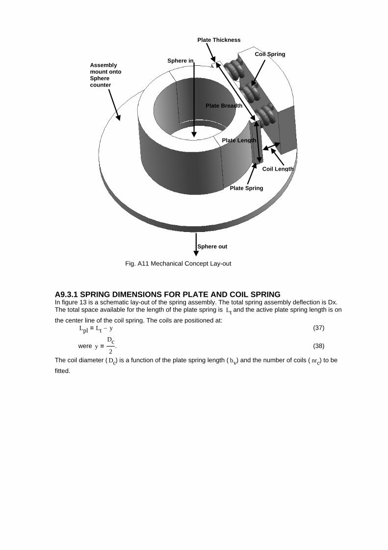
Sphere out
Plate Spring
Coil Spring
Coil Length
Assembly mount onto Sphere counter
Sphere in
Plate Length
Plate Thickness
Plate Breadth
Fig. A11 Mechanical Concept Lay-out
A9.3.1 SPRING DIMENSIONS FOR PLATE AND COIL SPRINGIn figure 13 is a schematic lay-out of the spring assembly. The total spring assembly deflection is Dx.The total space available for the length of the plate spring is Lt and the active plate spring length is on
the center line of the coil spring. The coils are positioned at: Lpl Lt y= (37)
were yDc
2= . (38)
The coil diameter ( Dc) is a function of the plate spring length ( bv) and the number of coils ( nrc) to be
fitted.
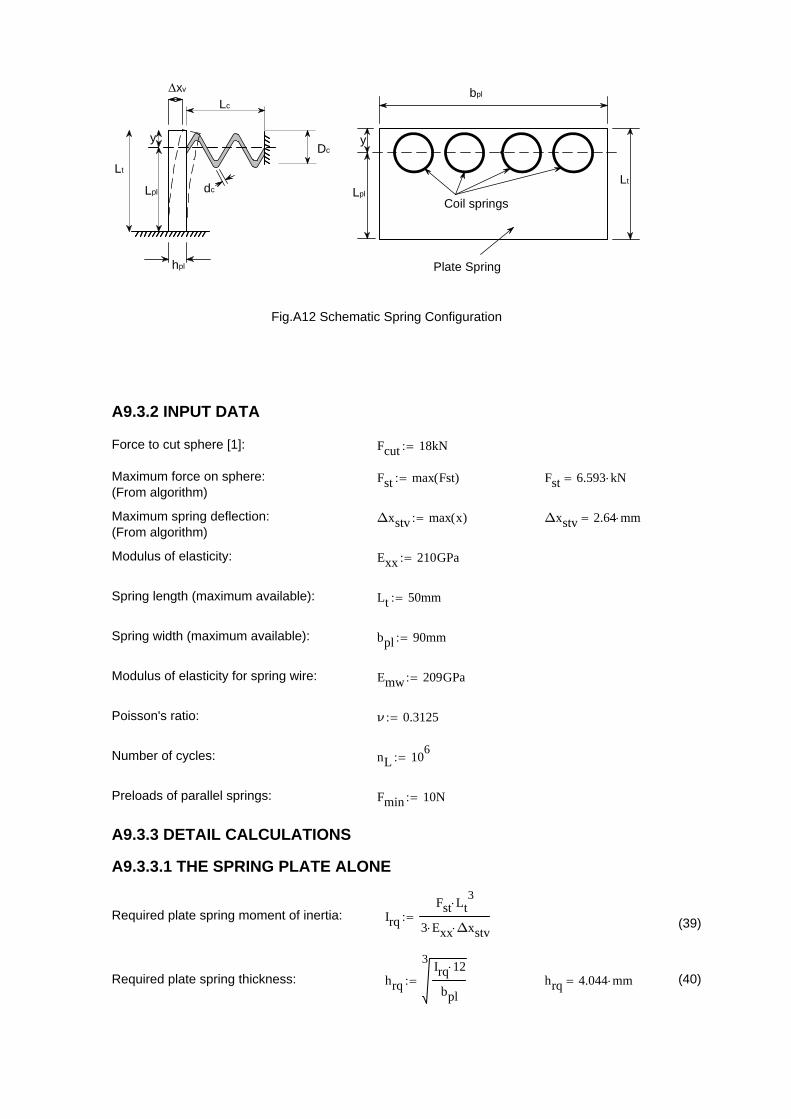
Lt
Lpl
yDc
Lc
dc
xv bpl
y
Lpl
Coil springs
Plate Spring
Lt
hpl
Fig.A12 Schematic Spring Configuration
A9.3.2 INPUT DATA
Force to cut sphere [1]: Fcut 18kN
Maximum force on sphere:(From algorithm)
Fst max Fst( ) Fst 6.593 kN
Maximum spring deflection:(From algorithm)
Δxstv max x( ) Δxstv 2.64 mm
Modulus of elasticity: Exx 210GPa
Spring length (maximum available): Lt 50mm
Spring width (maximum available): bpl 90mm
Modulus of elasticity for spring wire: Emw 209GPa
Poisson's ratio: ν 0.3125
Number of cycles: nL 106
Preloads of parallel springs: Fmin 10N
A9.3.3 DETAIL CALCULATIONS
A9.3.3.1 THE SPRING PLATE ALONE
Required plate spring moment of inertia: Irq
Fst Lt3
3 Exx Δxstv (39)
Required plate spring thickness: hrq
3Irq 12
bpl hrq 4.044 mm (40)
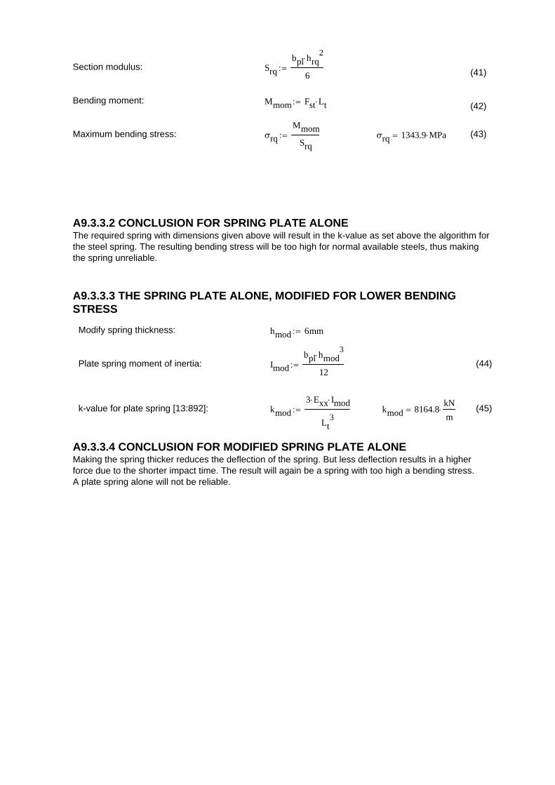
Section modulus: Srq
bpl hrq2
6 (41)
Bending moment: Mmom Fst Lt (42)
Maximum bending stress: σrq
Mmom
Srq σrq 1343.9 MPa (43)
A9.3.3.2 CONCLUSION FOR SPRING PLATE ALONEThe required spring with dimensions given above will result in the k-value as set above the algorithm forthe steel spring. The resulting bending stress will be too high for normal available steels, thus makingthe spring unreliable.
A9.3.3.3 THE SPRING PLATE ALONE, MODIFIED FOR LOWER BENDINGSTRESS
Modify spring thickness: hmod 6mm
Plate spring moment of inertia: Imod
bpl hmod3
12 (44)
k-value for plate spring [13:892]: kmod
3 Exx Imod
Lt3
kmod 8164.8kN
m (45)
A9.3.3.4 CONCLUSION FOR MODIFIED SPRING PLATE ALONEMaking the spring thicker reduces the deflection of the spring. But less deflection results in a higherforce due to the shorter impact time. The result will again be a spring with too high a bending stress. A plate spring alone will not be reliable.
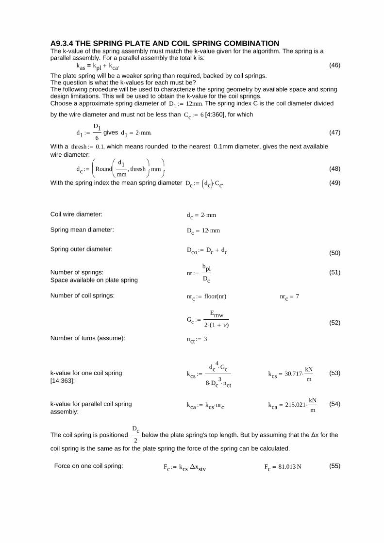
A9.3.4 THE SPRING PLATE AND COIL SPRING COMBINATIONThe k-value of the spring assembly must match the k-value given for the algorithm. The spring is aparallel assembly. For a parallel assembly the total k is:
kas kpl kca= . (46)
The plate spring will be a weaker spring than required, backed by coil springs.The question is what the k-values for each must be?The following procedure will be used to characterize the spring geometry by available space and springdesign limitations. This will be used to obtain the k-value for the coil springs.Choose a approximate spring diameter of D1 12mm . The spring index C is the coil diameter divided
by the wire diameter and must not be less than Cc 6 [4:360], for which
d1
D1
6 gives d1 2 mm . (47)
With a thresh 0.1 , which means rounded to the nearest 0.1mm diameter, gives the next availablewire diameter:
dc Roundd1
mmthresh
mm
. (48)
With the spring index the mean spring diameter Dc dc Cc . (49)
Coil wire diameter: dc 2 mm
Spring mean diameter: Dc 12 mm
Spring outer diameter: Dco Dc dc (50)
Number of springs:Space available on plate spring
nrbpl
Dc (51)
Number of coil springs: nrc floor nr( ) nrc 7
Gc
Emw
2 1 ν( ) (52)
Number of turns (assume): nct 3
k-value for one coil spring[14:363]:
kcs
dc4
Gc
8 Dc3
nct kcs 30.717
kN
m (53)
k-value for parallel coil springassembly:
kca kcs nrc kca 215.021kN
m (54)
The coil spring is positioned Dc
2 below the plate spring's top length. But by assuming that the Δx for the
coil spring is the same as for the plate spring the force of the spring can be calculated.
Force on one coil spring: Fc kcs Δxstv Fc 81.013 N (55)
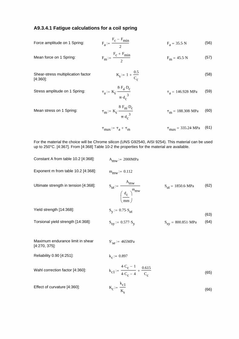
A9.3.4.1 Fatigue calculations for a coil spring
Force amplitude on 1 Spring: Fa
Fc Fmin
2 Fa 35.5 N (56)
Mean force on 1 Spring: Fm
Fc Fmin
2 Fm 45.5 N (57)
Shear-stress multiplication factor[4:360]:
Ks 10.5
Cc (58)
Stress amplitude on 1 Spring: τa Ks
8 Fa Dc
π dc3
τa 146.928 MPa (59)
Mean stress on 1 Spring: τm Ks
8 Fm Dc
π dc3
τm 188.308 MPa (60)
τmax τa τm τmax 335.24 MPa (61)
For the material the choice will be Chrome silicon (UNS G92540, AISI 9254). This material can be usedup to 250°C. [4:367]. From [4:368] Table 10-2 the properties for the material are available.
Constant A from table 10.2 [4:368]: Amw 2000MPa
Exponent m from table 10.2 [4:368]: mmw 0.112
Ultimate strength in tension [4:368]: Sut
Amw
dc
mm
mmw Sut 1850.6 MPa (62)
Yield strength [14:368]: Sy 0.75 Sut(63)
Torsional yield strength [14:368]: Ssy 0.577 Sy Ssy 800.851 MPa (64)
Maximum endurance limit in shear[4:270, 375]:
S'se 465MPa
Reliability 0.90 [4:251]: kc 0.897
Wahl correction factor [4:360]: kc1
4 Cc 1
4 Cc 4
0.615
Cc (65)
Effect of curvature [4:360]: Kc
kc1
Ks (66)
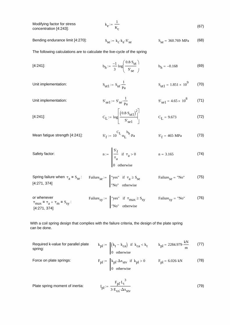
Modifying factor for stressconcentration [4:243]:
ke1
Kc (67)
Bending endurance limit [4:270]: Sse kc ke S'se Sse 360.769 MPa (68)
The following calculations are to calculate the live-cycle of the spring
[4:241]: bh1
3log
0.8 Sut
S'se
bh 0.168 (69)
Unit implementation: Sut1 Sut1
Pa Sut1 1.851 10
9 (70)
Unit implementation: S'se1 S'se1
Pa S'se1 4.65 10
8 (71)
[4:241]: CL log0.8 Sut1 2
S'se1
CL 9.673 (72)
Mean fatigue strength [4:241]: S'f 10CL
nL
bh Pa S'f 465 MPa (73)
Safety factor: nS'f
τaτa 0if
0 otherwise
n 3.165 (74)
Spring failure when τa Sse= :
[4:271, 374]
Failurese "yes" τa Sseif
"No" otherwise
Failurese "No" (75)
or whenever τmax τa τm= Ssy= :
[4:271, 374]
Failuresy "yes" τmax Ssyif
"No" otherwise
Failuresy "No" (76)
With a coil spring design that complies with the failure criteria, the design of the plate springcan be done.
Required k-value for parallel platespring:
kpl kt kca kca ktif
0 otherwise
kpl 2284.979kN
m (77)
Force on plate springs: Fpl kpl Δxstv kpl 0if
0 otherwise
Fpl 6.026 kN (78)
Plate spring moment of inertia: Ipl
Fpl Lt3
3 Exx Δxstv (79)
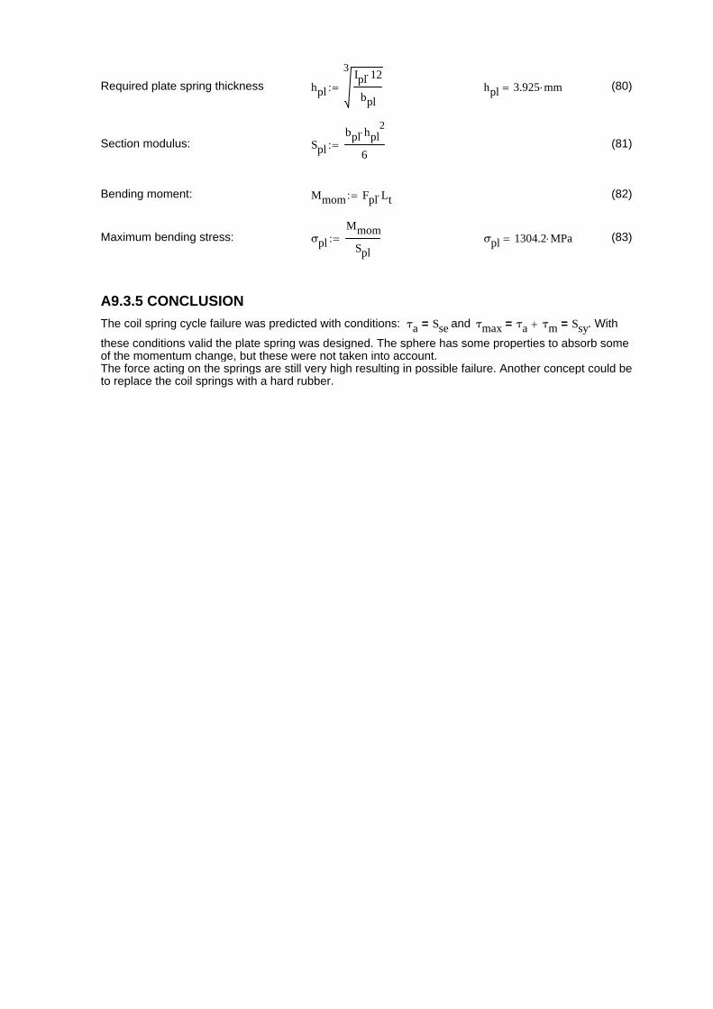
Required plate spring thickness hpl
3Ipl 12
bpl hpl 3.925 mm (80)
Section modulus: Spl
bpl hpl2
6 (81)
Bending moment: Mmom Fpl Lt (82)
Maximum bending stress: σpl
Mmom
Spl σpl 1304.2 MPa (83)
A9.3.5 CONCLUSION
The coil spring cycle failure was predicted with conditions: τa Sse= and τmax τa τm= Ssy= . With
these conditions valid the plate spring was designed. The sphere has some properties to absorb someof the momentum change, but these were not taken into account. The force acting on the springs are still very high resulting in possible failure. Another concept could beto replace the coil springs with a hard rubber.
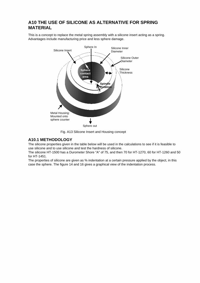
A10 THE USE OF SILICONE AS ALTERNATIVE FOR SPRINGMATERIAL
This is a concept to replace the metal spring assembly with a silicone insert acting as a spring.Advantages include manufacturing price and less sphere damage.
Sphere In Silicone Insert
Silicone Thickness
Metal Housing: Mounted onto sphere counter
Sphere out
Spindle Rotation
Sphere contact
area
Silicone Outer Diameter
Silicone Inner Diameter
Fig. A13 Silicone Insert and Housing concept
A10.1 METHODOLOGYThe silicone properties given in the table below will be used in the calculations to see if it is feasible touse silicone and to use silicone and test the hardness of silicone. The silicone HT-1500 has a Durometer Shore "A" of 75, and then 70 for HT-1270, 60 for HT-1260 and 50for HT-1451.The properties of silicone are given as % indentation at a certain pressure applied by the object, in thiscase the sphere. The figure 14 and 16 gives a graphical view of the indentation process.
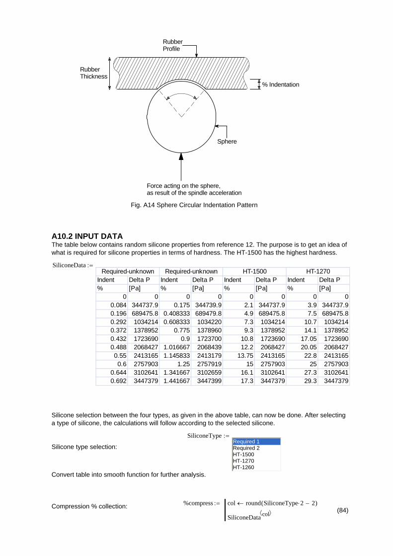
RubberThickness
% Indentation
Sphere
RubberProfile
Force acting on the sphere,as result of the spindle acceleration
Fig. A14 Sphere Circular Indentation Pattern
A10.2 INPUT DATAThe table below contains random silicone properties from reference 12. The purpose is to get an idea ofwhat is required for silicone properties in terms of hardness. The HT-1500 has the highest hardness.
SiliconeData
Indent Delta P Indent Delta P Indent Delta P Indent Delta P% [Pa] % [Pa] % [Pa] % [Pa]
0 0 0 0 0 0 0 00.084 344737.9 0.175 344739.9 2.1 344737.9 3.9 344737.90.196 689475.8 0.408333 689479.8 4.9 689475.8 7.5 689475.80.292 1034214 0.608333 1034220 7.3 1034214 10.7 10342140.372 1378952 0.775 1378960 9.3 1378952 14.1 13789520.432 1723690 0.9 1723700 10.8 1723690 17.05 17236900.488 2068427 1.016667 2068439 12.2 2068427 20.05 20684270.55 2413165 1.145833 2413179 13.75 2413165 22.8 24131650.6 2757903 1.25 2757919 15 2757903 25 2757903
0.644 3102641 1.341667 3102659 16.1 3102641 27.3 31026410.692 3447379 1.441667 3447399 17.3 3447379 29.3 3447379
Required-unknown HT-1500 HT-1270Required-unknown
Silicone selection between the four types, as given in the above table, can now be done. After selectinga type of silicone, the calculations will follow according to the selected silicone.
SiliconeTypeRequired 1Required 2HT-1500HT-1270HT-1260
Silicone type selection:
Convert table into smooth function for further analysis.
%compress col round SiliconeType 2 2( )
SiliconeData col Compression % collection:
(84)

Pressure col round SiliconeType 2 1( )
SiliconeData col (85)
Pressure collection:
Spline form: vs lspline %compress Pressure( ) (86)
Pressure interpolation: Prubber %c linterp %compress Pressure %c Pa (87)
0 0.5 10
2 103
4 103
6 103
8 103
1 104
Fig. A15 Rubber Hardness
Percent Compression [%]
Pre
ssur
e on
rub
ber
[kP
a]
Torque limiter max torque Ttls 300N m
Torque limiter force on sphere: Ftls
Ttls
Dsp 0.5 Ftls 937.5 N (88)
Sphere diameter: dsf 60mm
Sphere radius: rsf
dsf
2
(89)
Rubber thickness: tr 20mm
Rubber inner radius: rri64.8
2mm (90)
Rubber outer diameter: dro rri tr 2 dro 104.8 mm (91)
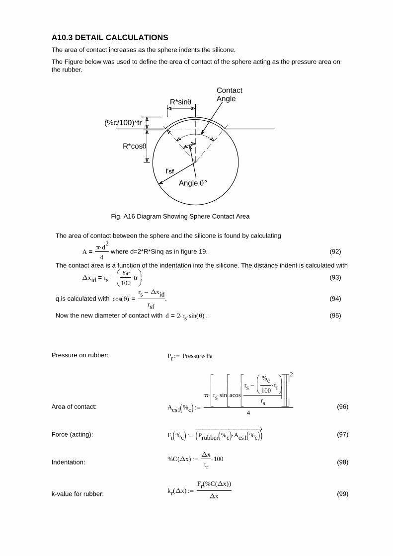
A10.3 DETAIL CALCULATIONS
The area of contact increases as the sphere indents the silicone.
The Figure below was used to define the area of contact of the sphere acting as the pressure area onthe rubber.
rsf
ContactAngle
Angle °
R*sin
R*cos
(%c/100)*tr
Fig. A16 Diagram Showing Sphere Contact Area
The area of contact between the sphere and the silicone is found by calculating
Aπ d
2
4= where d=2*R*Sinq as in figure 19. (92)
The contact area is a function of the indentation into the silicone. The distance indent is calculated with
Δxid rs%c
100tr
= . (93)
q is calculated with cos θ( )rs Δxid
rsf= . (94)
Now the new diameter of contact with d 2 rs sin θ( )= . (95)
Pressure on rubber: Pr Pressure Pa
Area of contact: Acs1 %c π rs sin acos
rs
%c
100tr
rs
2
4 (96)
Force (acting): Fr %c Prubber %c Acs1 %c
(97)
%C Δx( )Δx
tr100Indentation: (98)
kr Δx( )Fr %C Δx( )( )
Δxk-value for rubber: (99)
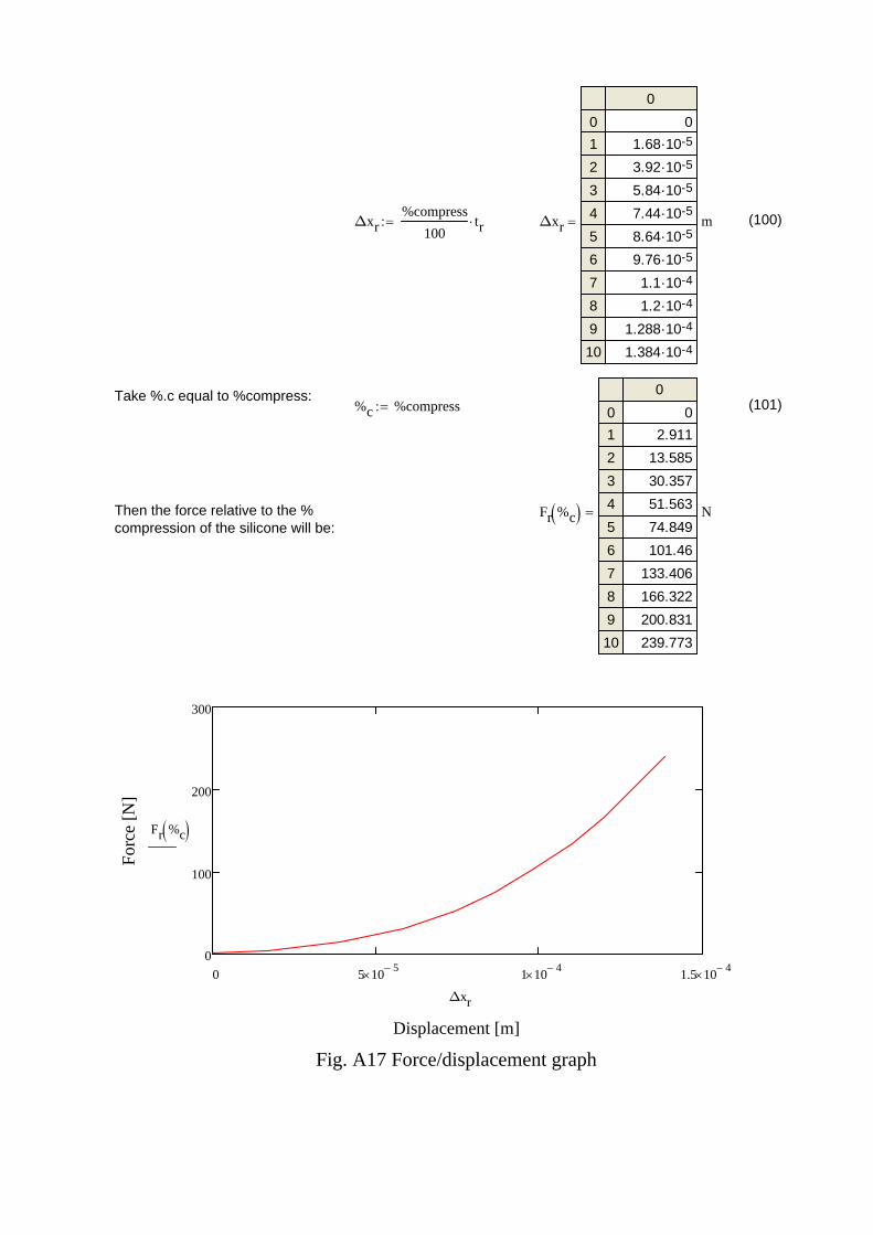
Δxr%compress
100tr Δxr
0
01
2
3
4
5
6
7
8
9
10
0-51.68·10-53.92·10-55.84·10-57.44·10-58.64·10-59.76·10-41.1·10-41.2·10-41.288·10-41.384·10
m (100)
Take %.c equal to %compress:%c %compress (101)
Then the force relative to the %compression of the silicone will be:
Fr %c
0
01
2
3
4
5
6
7
8
9
10
02.911
13.585
30.357
51.563
74.849
101.46
133.406
166.322
200.831
239.773
N
0 5 105 1 10
4 1.5 104
0
100
200
300
Fig. A17 Force/displacement graph
Displacement [m]
For
ce [
N]
Fr %c
Δxr
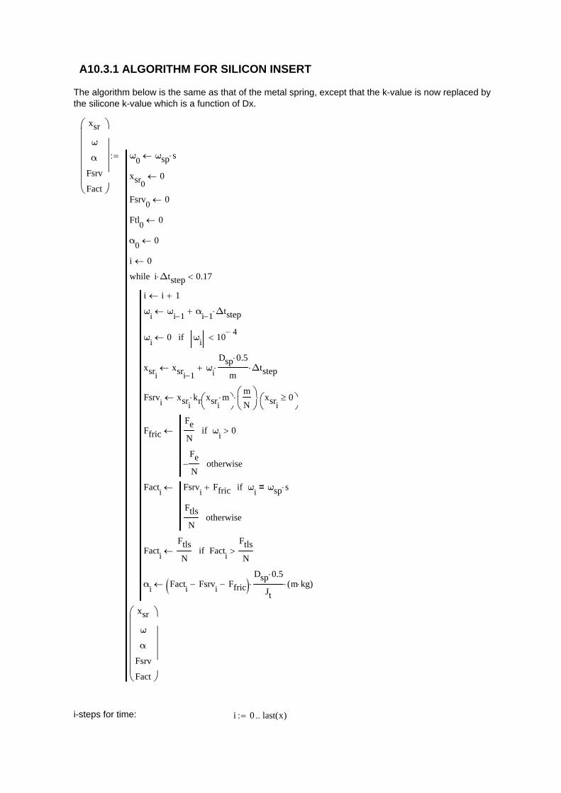
A10.3.1 ALGORITHM FOR SILICON INSERT
The algorithm below is the same as that of the metal spring, except that the k-value is now replaced bythe silicone k-value which is a function of Dx.
xsr
ω
α
Fsrv
Fact
ω0
ωsp s
xsr00
Fsrv0
0
Ftl0
0
α0
0
i 0
i i 1
ωi
ωi 1 α
i 1 Δtstep
ωi
0 ωi
104
if
xsrixsri 1
ωi
Dsp 0.5
m Δtstep
Fsrvi
xsrikr xsri
m
m
N
xsri0
Ffric
Fe
Nω
i0if
Fe
N otherwise
Facti
Fsrvi
Ffric ωi
ωsp s=if
Ftls
Notherwise
Facti
Ftls
N Fact
i
Ftls
Nif
αi
Facti
Fsrvi
Ffric Dsp 0.5
Jt m kg( )
i Δtstep 0.17while
xsr
ω
α
Fsrv
Fact
i-steps for time: i 0 last x( )
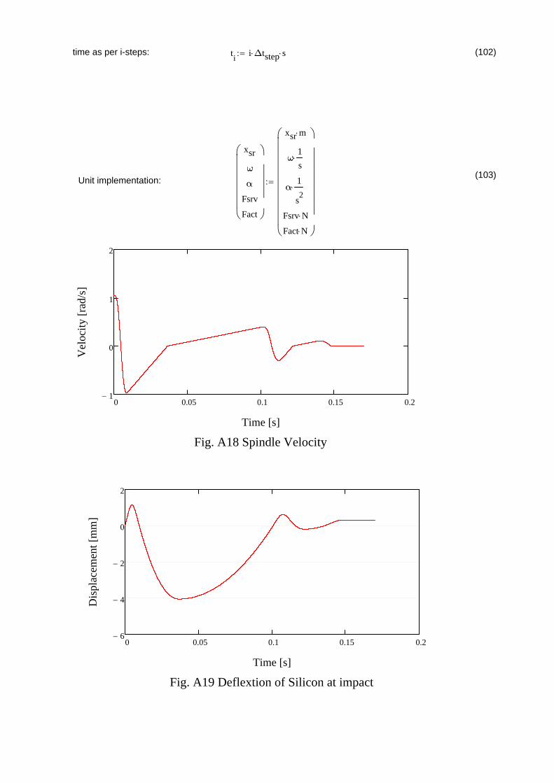
time as per i-steps: ti
i Δtstep s (102)
(103)Unit implementation:
xsr
ω
α
Fsrv
Fact
xsr m
ω1
s
α1
s2
Fsrv N
Fact N
0 0.05 0.1 0.15 0.21
0
1
2
Fig. A18 Spindle Velocity
Time [s]
Vel
ocit
y [r
ad/s
]
0 0.05 0.1 0.15 0.26
4
2
0
2
Fig. A19 Deflextion of Silicon at impact
Time [s]
Dis
plac
emen
t [m
m]

0 0.1 0.2 0.3 0.40
10
20
30
Spring ForceActuator ForceSphere Cut Force
Fig. A20 Acting Forces
Time [s]
Act
ing
For
ces
[kN
]
Spring constant at maximum force: ksmax Fsrv( )
max xsr ks 19660.85
kN
m (104)
A10.4 CONCLUSION:
The calculations for the silicone spring options started with the table containing four randomsilicone properties. During the calculations it was found that all four selections was too soft. Afifth column was added after running the algorithm and by changing the data in the columniteratively properties of what should be required was derived. This iteration was also done whilechanging the torque limiter setting. The torque limiter and spring constant in combination givethe amount of head return. The idea is currently to let the head travel back to before the impactpoint to release the sphere.Silicone does not have a straight line for a spring constant, but the spring constant given aboveat maximum impact force relates to the spring constant required from the metal spring. In this algorithm the sphere impacted on a straight silicone strip with a straight forward impact,but the right insert will be found that will result in a greater impact area and therefore lessindentation into the silicone.The result is that silicone can be used for a spring. It can fit in the same position in the housingas the metal spring.

A11 CALCULATE SHAFT PROPERTIES FOR TORQUE TRANSMITTING
A11.1 METHODOLOGY OF SHAFT CALCULATIONThe Penetration shaft and the head shaft are the two shafts to be used. The material properties for theshafts to be able to cut spheres will be calculated by selecting the weakest part of each shaft. Theweakest part of the penetration shaft is the 30mm diameter part and in the penetration shaft the 27mmsquare at the end. Figure 4 shows a picture of both shafts indicating the critical points.
30mmSpline
Square
Splines (Inside)
Fig.A21 Penetration shaft (Left) and head shaft (Right)
A11.2 INPUT DATA
EN 24 (Condition V)steel yield stress:
σ24 835MPa [5]
If the shafts can be replaced we do not need a safety factor as high as 3 for fatigue, thus in thiscase a safety factor of 1.2 was used.
Safety factor: Sf 1.2
Effective radius of square: rsq35mm
2 (105)
The actual effective square radius will be a bit more because the square is a bit larger than theinscribed square.
Square section of penetration shaft: bsq 27mm
Shaft diameter (smallest dia): Dsp1 30mm
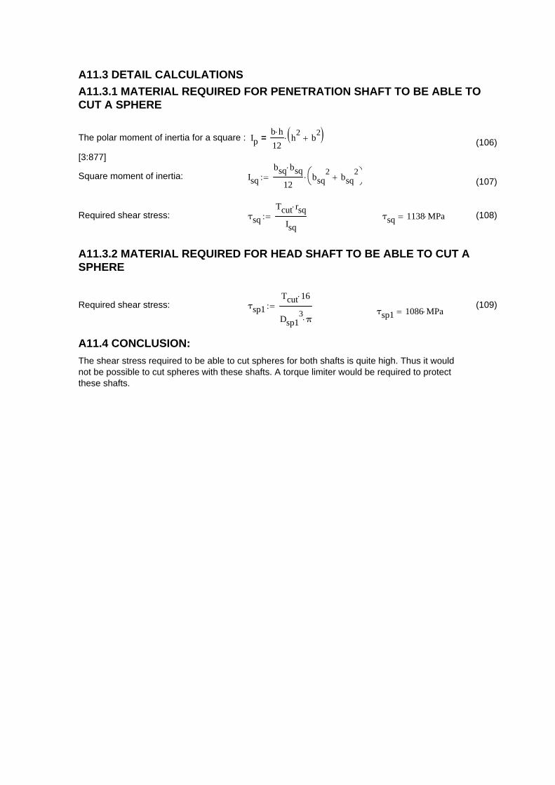
A11.3 DETAIL CALCULATIONS
A11.3.1 MATERIAL REQUIRED FOR PENETRATION SHAFT TO BE ABLE TOCUT A SPHERE
The polar moment of inertia for a square : Ipb h
12h
2b
2 =
[3:877]
(106)
Square moment of inertia: Isq
bsq bsq
12bsq
2bsq
2
(107)
Required shear stress: τsq
Tcut rsq
Isq τsq 1138 MPa (108)
A11.3.2 MATERIAL REQUIRED FOR HEAD SHAFT TO BE ABLE TO CUT ASPHERE
Required shear stress: τsp1
Tcut 16
Dsp13
π (109)
τsp1 1086 MPa
A11.4 CONCLUSION:
The shear stress required to be able to cut spheres for both shafts is quite high. Thus it wouldnot be possible to cut spheres with these shafts. A torque limiter would be required to protectthese shafts.
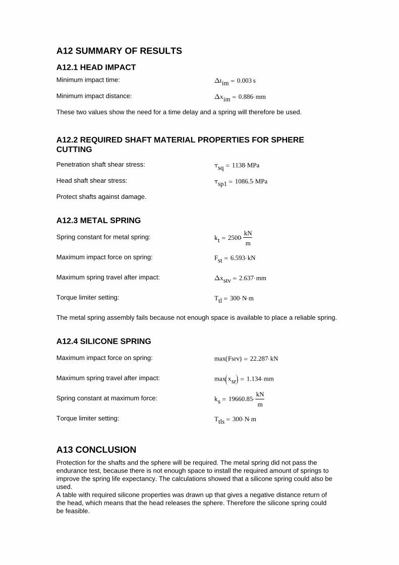
A12 SUMMARY OF RESULTS
A12.1 HEAD IMPACT
Minimum impact time: Δtim 0.003 s
Minimum impact distance: Δxim 0.886 mm
These two values show the need for a time delay and a spring will therefore be used.
A12.2 REQUIRED SHAFT MATERIAL PROPERTIES FOR SPHERECUTTING
Penetration shaft shear stress: τsq 1138 MPa
Head shaft shear stress: τsp1 1086.5 MPa
Protect shafts against damage.
A12.3 METAL SPRING
Spring constant for metal spring: kt 2500kN
m
Maximum impact force on spring: Fst 6.593 kN
Maximum spring travel after impact: Δxstv 2.637 mm
Torque limiter setting: Ttl 300 N m
The metal spring assembly fails because not enough space is available to place a reliable spring.
A12.4 SILICONE SPRING
Maximum impact force on spring: max Fsrv( ) 22.287 kN
Maximum spring travel after impact: max xsr 1.134 mm
Spring constant at maximum force: ks 19660.85kN
m
Torque limiter setting: Ttls 300 N m
A13 CONCLUSIONProtection for the shafts and the sphere will be required. The metal spring did not pass theendurance test, because there is not enough space to install the required amount of springs toimprove the spring life expectancy. The calculations showed that a silicone spring could also beused.A table with required silicone properties was drawn up that gives a negative distance return ofthe head, which means that the head releases the sphere. Therefore the silicone spring couldbe feasible.
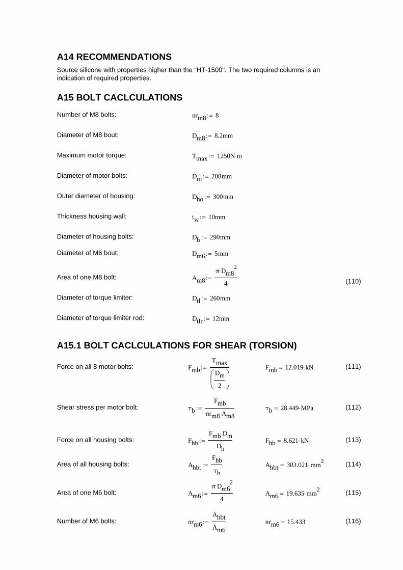
A14 RECOMMENDATIONSSource silicone with properties higher than the "HT-1500". The two required columns is anindication of required properties.
A15 BOLT CACLCULATIONS
Number of M8 bolts: nrm8 8
Diameter of M8 bout: Dm8 8.2mm
Maximum motor torque: Tmax 1250N m
Diameter of motor bolts: Dm 208mm
Outer diameter of housing: Dho 300mm
Thickness housing wall: tw 10mm
Diameter of housing bolts: Dh 290mm
Diameter of M6 bout: Dm6 5mm
Area of one M8 bolt: Am8
π Dm82
4 (110)
Diameter of torque limiter: Dtl 260mm
Diameter of torque limiter rod: Dtlr 12mm
A15.1 BOLT CACLCULATIONS FOR SHEAR (TORSION)
Force on all 8 motor bolts: Fmb
Tmax
Dm
2
Fmb 12.019 kN (111)
Shear stress per motor bolt: τb
Fmb
nrm8 Am8 τb 28.449 MPa (112)
Force on all housing bolts: Fhb
Fmb Dm
Dh Fhb 8.621 kN (113)
Area of all housing bolts: Ahbt
Fhb
τb Ahbt 303.021 mm
2 (114)
Area of one M6 bolt: Am6
π Dm62
4 Am6 19.635 mm
2 (115)
Number of M6 bolts: nrm6
Ahbt
Am6 nrm6 15.433 (116)

15.2 BOLT CACLCULATIONS FOR TENSION (MOTOR WEIGHT)
Motor mass: Mm 14.5kg
Motor mass: Mw Mm g Mw 142.196 N (117)
A15.3 TORQUE LIMITER STOP
Fig.A22 Fixing to prevent Torque Limiter rotation
Force on anchor pin (Torque limiter): Fatl
Tmax
Dtl
2
Fatl 9615.4 N (118)
Force on anchor pin (Housing): Fah
Tmax
Dh
2
Fah 8620.7 N (119)
Resulting force on pin: Fra Fatl Fah Fra 994.695 N (120)
A15.4 TORQUE ON COVER SHELL
Inner diameter of housing: Di Dho2 Ahbt 4
π Di 299.356 mm (121)
Housing thickness: th
Dho Di 2
th 0.322 mm (122)
Safety margin for max torque: nsm
tw th
tw
100 nsm 96.8 (123)
