f-800 and f-1000 mud pump charles specification and ... product conform to api spec 7k, f-800 and...
TRANSCRIPT

This product conform to API Spec 7K,
F-800 and F-1000 MUD PUMP
Specification and Performance
Distributed by
Charles Rig Supplies, Inc.
Charles Rig Supplies, Inc.
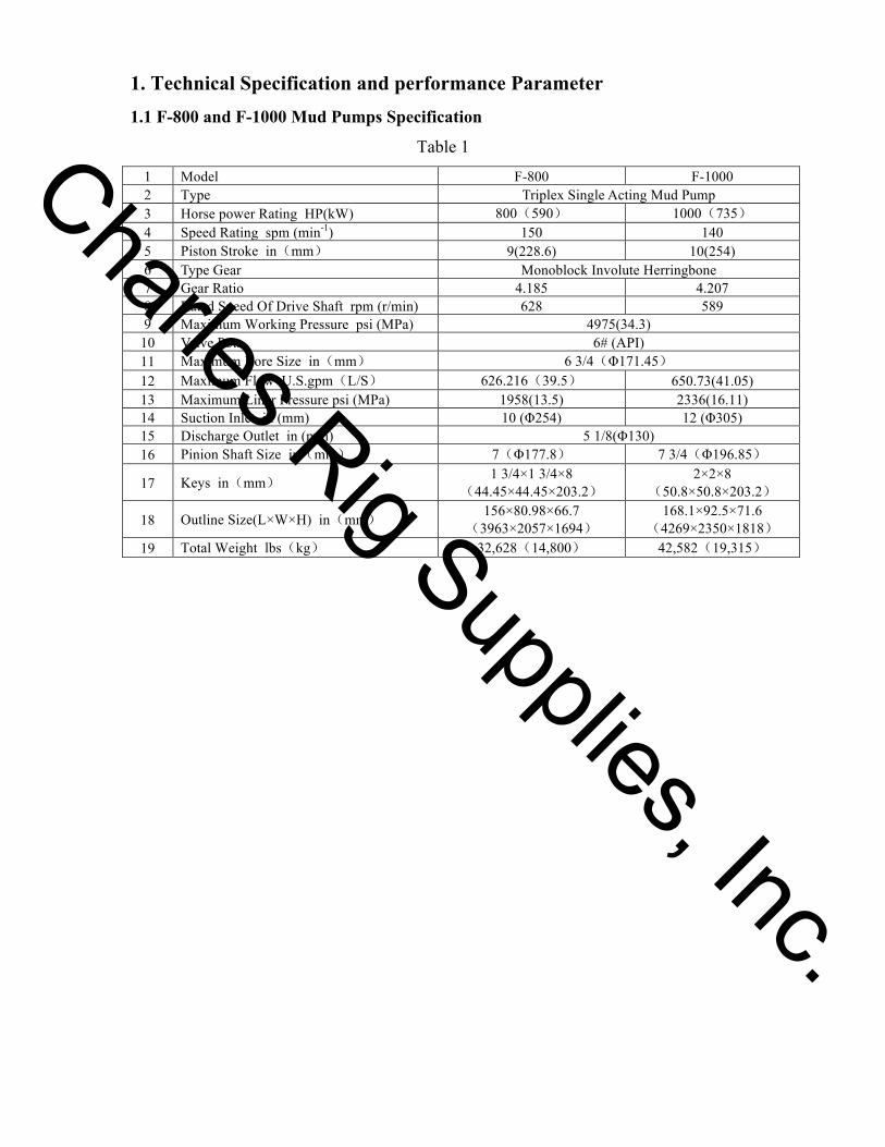
1. Technical Specification and performance Parameter 1.1 F-800 and F-1000 Mud Pumps Specification
Table 1
1 Model F-800 F-1000 2 Type Triplex Single Acting Mud Pump 3 Horse power Rating HP(kW) 800(590) 1000(735) 4 Speed Rating spm (min-1) 150 140 5 Piston Stroke in(mm) 9(228.6) 10(254) 6 Type Gear Monoblock Involute Herringbone 7 Gear Ratio 4.185 4.207 8 Rated Speed Of Drive Shaft rpm (r/min) 628 589 9 Maximum Working Pressure psi (MPa) 4975(34.3)
10 Valve Pots 6# (API) 11 Maximum Bore Size in(mm) 6 3/4(Φ171.45) 12 Maximum Flow U.S.gpm(L/S) 626.216(39.5) 650.73(41.05) 13 Maximum Liner Pressure psi (MPa) 1958(13.5) 2336(16.11) 14 Suction Inlet in (mm) 10 (Φ254) 12 (Φ305) 15 Discharge Outlet in (mm) 5 1/8(Φ130) 16 Pinion Shaft Size in(mm) 7(Φ177.8) 7 3/4(Φ196.85)
17 Keys in(mm) 1 3/4×1 3/4×8(44.45×44.45×203.2)
2×2×8(50.8×50.8×203.2)
18 Outline Size(L×W×H) in(mm) 156×80.98×66.7(3963×2057×1694)
168.1×92.5×71.6(4269×2350×1818)
19 Total Weight lbs(kg) 32,628(14,800) 42,582(19,315)
Charles Rig Supplies, Inc.
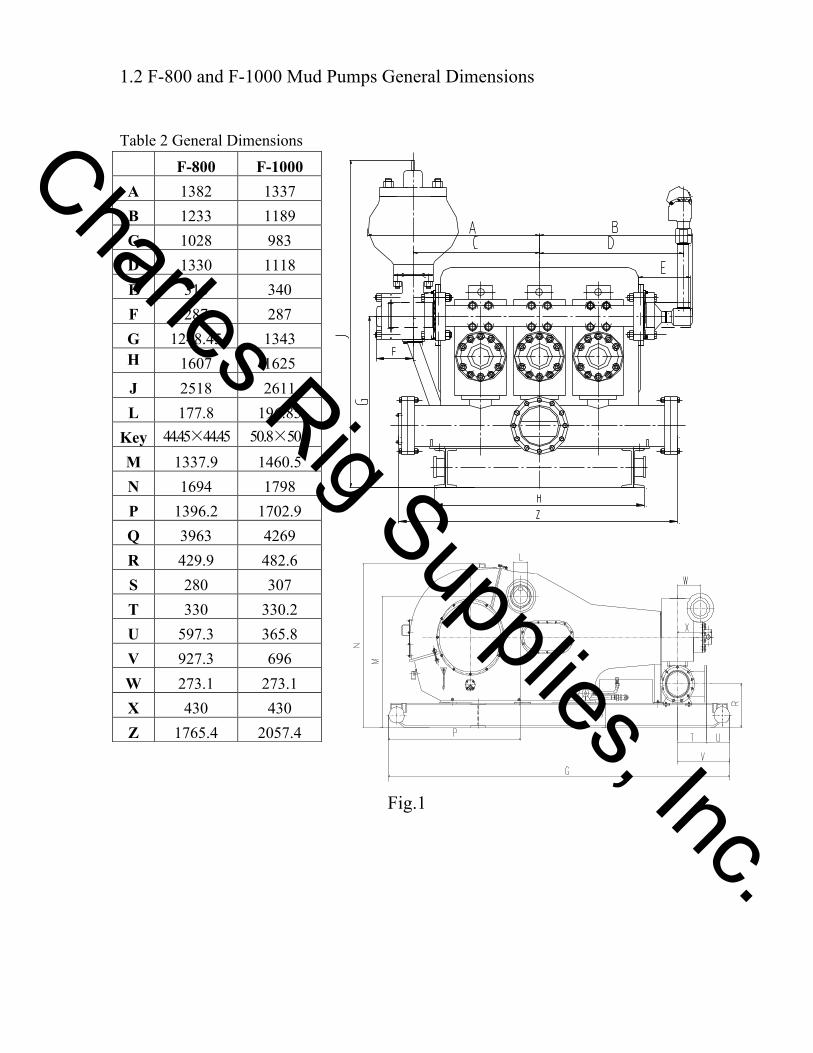
1.2 F-800 and F-1000 Mud Pumps General Dimensions
Table 2 General Dimensions
Fig.1
F-800 F-1000 A 1382 1337 B 1233 1189 C 1028 983 D 1330 1118 E 316 340 F 287 287 G 1248.45 1343 H 1607 1625 J 2518 2611 L 177.8 196.85
Key 44.45×44.45 50.8×50.8 M 1337.9 1460.5 N 1694 1798 P 1396.2 1702.9 Q 3963 4269 R 429.9 482.6 S 280 307 T 330 330.2 U 597.3 365.8 V 927.3 696 W 273.1 273.1 X 430 430 Z 1765.4 2057.4
Charles Rig Supplies, Inc.
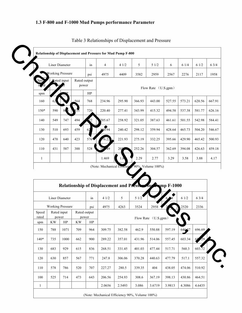
1.3 F-800 and F-1000 Mud Pumps performance Parameter
Table 3 Relationships of Displacement and Pressure
Relationship of Displacement and Pressure for Pump F-1000
Liner Diameter in 4 1/2 5 5 1/2 6 6 1/4 6 1/2 6 3/4
Working Pressure psi 4975 4263 3524 2958 2726 2520 2336 Speed rated
Rated input power
Rated output power Flow Rate (U.S.gpm)
spm KW HP KW HP
150 788 1071 709 964 309.75 382.58 462.9 550.88 597.19 646.37 696.69
140* 735 1000 662 900 289.22 357.01 431.96 514.06 557.45 603.34 650.29
130 683 929 615 836 268.51 331.45 401.03 477.44 517.71 560.3 603.72
120 630 857 567 771 247.8 306.06 370.28 440.63 477.79 517.1 557.32
110 578 786 520 707 227.27 280.5 339.35 404 438.05 474.06 510.92
100 525 714 473 643 206.56 254.93 308.6 367.19 398.13 430.86 464.51
1 2.0656 2.5493 3.086 3.6719 3.9813 4.3086 4.6435
(Note: Mechanical Efficiency 90%, Volume 100%)
Relationship of Displacement and Pressure for Mud Pump F-800
Liner Diameter in 4 4 1/2 5 5 1/2 6 6 1/4 6 1/2 6 3/4
Working Pressure psi 4975 4409 3582 2959 2567 2276 2117 1958
Speed rated
Rated input power
Rated output power
Flow Rate (U.S.gpm) spm HP HP
160 627 853 564 768 234.96 295.90 366.93 443.00 527.55 573.21 620.56 667.91
150* 590 800 531 720 220.40 277.41 343.99 415.32 494.58 537.38 581.77 626.16
140 549 747 494 672 205.67 258.92 321.05 387.63 461.61 501.55 542.98 584.41
130 510 693 459 624 190.94 240.42 298.12 359.94 428.64 465.73 504.20 546.67
120 470 640 423 576 176.22 221.93 275.19 332.25 395.66 429.90 465.42 500.93
110 431 587 388 528 161.49 203.43 252.26 304.57 362.69 394.08 426.63 459.18
1 1.469 1.85 2.29 2.77 3.29 3.58 3.88 4.17
(Note: Mechanical Efficiency 90%, Volume 100%)
Charles Rig Supplies, Inc.
2. Structure Features 2.1 Power End Features
a. The Frame The frame is made of welded steel plate and stress relief treated to
obtain the good rigidity and high strength. The place where the crankshaft bearing is
fitted is strengthened by using ribbed plates. The frame is furnished with the necessary oil
basin and oil way system for cooling and lubricating purpose.
b. The Pinion Shaft The pinion shaft is made of forged alloy steel on which a
herringbone gear with the medium-hard tooth surface is machined. For easy maintenance,
the single row radial long cylindrical roller bearing with inner ring (without sides) is
used. The both ends of the pinion shaft extend out, so that the sheave or the sprocket can
be mounted on either end.
c. The Crankshaft The crankshaft is made of cast alloy steel and furnished with
herringbone gear, connecting rod and bearing. The tooth form of the big-geared ring is
herringbone gear. The gear bore and the crankshaft surfaces are interference fitted and
they are both fastened with bolts and lock nuts. The big end of the connecting rod is
mounted on three eccentric straps of the crankshaft through single row short cylindrical
roller bearings and the small end on the crosshead pin through double row long
cylindrical roller bearing. Double row radial spherical roller bearings are mounted at both
ends of the crankshaft.
d. The Crosshead And Crosshead Guide The crosshead and crosshead guide are
made of homebred meehanite cast iron featured by good abrasion resistance and long
service life. Upper and lower guides are used for mud pump, so that the concentricity can
be adjusted by adding shims beneath the lower guide. The connection between the
crosshead and the extension rod is made by using bolted flange. The rigid connection
ensures the concentricity of the crosshead and the extension rod. The coupling is used for
connecting the extension rod to the piston rod. The lightweight coupling enables the
extension rod and the piston rod to connect to each other easily and reliably.
e. The Extension Rod Packing. The extension rod packing is duplex seal structure
to provide the good seal result.
f. The Power End. The power end uses the combined lubricating system of forced
lubrication and splash lubrication.
Charles Rig Supplies, Inc.
2.2 Fluid End Features
a. Cylinders Cylinders are made of forged alloy steel, three cylinders of each pump
are interchangeable. Valve-over-valve (through type cylinder) design reduces the
cylinder volume and promotes the volumetric efficiency. At customers’request,
the cylinder surface may be nickel plated to improve the abrasion resistance.
b. Discharge pulsation dampener, shear relief valve and discharge block are
furnished at the outlet. F-800 pump suction inlet with 10" flange and F-1000
pump suction inlet with 12" flange. c. Valve Assembly The suction valve and the discharge valve for F-800 and F-1000
mud pumps are interchangeable. F-800 and F-1000 mud pump uses API 6# valve
pots.
d. Liners Bi-metal liners are used. The sleeve is made of wear-resistant cast iron, the
surface hardness is HRC60~65. Therefore, liners feature wear resistance,
corrosion resistance and high surface finish. Liners are put in from the cylinder
cover bore in the front of the cylinder and fixed with liner cage, cylinder cover
plug and cylinder cover when installing.
e. Pistons And Piston Rods They are slide fitted, sealed with rubber seal ring and
finally fastened with lock nuts to prevent the piston from looseness and to play a
role in sealing.
Cylinders, liners, pistons, valves, valve seats, valve springs, seal rings, valve
pot covers and cylinder covers at the fluid end of F-800 and F-1000 mud pumps
are all interchangeable.
f. Spraying System The spraying system consists mainly of spray pump, cooling
water box, and spray pipe, the function is to cool and rinse liners and pistons to
promote their service life.
The centrifugal spray pump can be driven by a sheave mounted on the input
shaft extension end or a separate motor and cooled and lubricated by water.
Follow-up pray pipe is used. The spray pipe is mounted on the piston rod clamp
and the frame. Nozzle is face to the piston end so that the lubricating-cooling fluid
can rinse the contact surface between the piston and liner all the time.
g. Lubricating System The power end uses the combined lubricating system of
forced lubrication and splash lubrication. The pressure oil is conveyed through
lubricating pipeline, crosshead, extension rod, crosshead guide and all bearings by
Charles Rig Supplies, Inc.
a gear oil pump within the oil box to realize the forced lubrication. The working
condition of the gear oil pump may be understood from the pressure gauge behind
the frame.
h. Charging System To prevent the air lock occurring for low pump inlet pressure,
every mud pump should be furnished with a complete charging system. It consists
of charging pump,pump base, butterfly valve and corresponding manifold.
Mounted on the suction manifold of the mud pump, the charging pump is driven
by the special purpose motor or the input shaft of the mud pump through V-belts
to reduce the power consumption.
Charles Rig Supplies, Inc.