ez flange spiral pipe – sheet metal connectors
DESCRIPTION
Sheet Metal Connectors, Inc. E-Z Flange spiral pipe and fittings are one part of our complete line of HVAC products. The spiral pipe is formed from a coil of metal into a rigid tube with a 4-ply lockseam. It has a smooth interior low friction loss with the grooved seam entirely on the outside. This pipe has a resistance to crushing approximately 2 1/2 times that of longitudinal lockseam or welded pipe. Optional corrugations are available which increase the rigidity of the pipe by approximately 300%. Pipe sections are joined together by an E-Z Flange Jr. or an E-Z Flange with barrel clamp, which exceeds ASHRAE and SMACNA Class 3 Leakage Tests.TRANSCRIPT


Corporate Headquarters
SHEET METAL CONNECTORS, INC.5850 MAIN STREET N.E. • MINNEAPOLIS, MINNESOTA 55432
Toll Free: 800-328-1966 Local: 763-572-0000 Fax: 763-572-1100www.smcduct.com
Manufacturing Facilities5850 Main Street N.E. 5601 Sandy Hollow RoadMinneapolis, MN 55432 Rockford, IL 61109LOCAL: 763-572-0000 LOCAL: 815-874-4600TOLL FREE: 1-800-328-1966 TOLL FREE: 1-866-504-4600FAX: 763-572-1100 FAX: 815-874-9979
Sheet Metal Connectors, Inc. is proud to be a member or affiliatedwith the following associations;
Sheet Metal Workers’ International AssociationWashington, DC
Sheet Metal Air Conditioning Contractors’National AssociationChantilly, VA
SPIDASpiral Duct Manufacturers AssociationIrmo, SC
SMACNA Testing & Research InstituteChantilly, VA

1
May 2013
The E-Z Flange Spiral Pipe System
Sheet Metal Connectors, Inc. E-Z Flange spiral pipe and fittings are one part of our complete line of HVAC products. The spiral pipe is formed from a coil of metal into a rigid tube with a 4-ply lockseam. It has a smooth interior low friction loss with the grooved seam entirely on the outside. This pipe has a resistance to crushing approximately 2 1/2 times that of longitudinal lockseam or welded pipe. Optional cor-rugations are available which increase the rigidity of the pipe by approximately 300%. Pipe sections are joined together by an E-Z Flange Jr. or an E-Z Flange with barrel clamp, which exceeds ASHRAE and SMACNA Class 3 Leakage Tests.
DIAMETER MATERIAL THICKNESS ASTM TYPE LENGTH
6” - 24” Galvanized 26 - 20 gauge A-653 G60-G90 1’ – 20’; 9’ 11” Standard
6” - 24” Paint Grip 24 - 20 gauge A-653 A60 1’ – 20’; 9’ 11” Standard
6” - 24” PVS 24 - 20 gauge A-653 4 x 1, 4 x 4 1’ – 20’; 9’ 11” Standard
6” - 24” Aluminum .032 - .048 B-316 3003 H-14 1’ – 20’; 9’ 11” Standard
E-Z Flange Jr. with Barrel Clamp 6” – 24” Diameter
DIAMETER MATERIAL THICKNESS ASTM TYPE LENGTH
26” - 96” Galvanized 26 - 14 gauge A-653 G60-G90 1’ – 20’; 10’ Standard
26” - 96” Paint Grip 24 - 18 gauge A-653 A60 1’ – 20’; 10’ Standard
26” - 96” PVS 24 - 16 gauge A-653 4 x 1, 4 x 4 1’ – 20’; 10’ Standard
26” - 96” Aluminum .032 - .063 B-316 3003 H-14 1’ – 20’; 10’ Standard
E-Z Flange with Barrel Clamp 26” – 96” Diameter
Note: SMACNA Testing and Research Institute verified that Sheet Metal Connectors, Inc.shop standards comply with the 2005-3rd edition of the SMACNA HVAC Duct Construction Standards.
5" 5"
5
5" 5"
5
5" 5"
5
Lateral section of 4-ply pressure-proof spiral seam.
Lateral section of grooved seam with optional corrugated grooves.
Optional culvert groove.
5”
5”
5”
Sheet Metal Connectors, Inc. is proud to be a member or affiliatedwith the following associations;

2E-Z Flange Jr. Spiral Pipe System
The E-Z Flange Jr. Spiral Pipe System has a 5/8” flange roll formed directly on the ends of the spiral pipe and fittings. Since the flange is part of the pipe and fittings, it adds rigidity and there is no chance for leakage. With no protrusions in the air stream to disrupt the airflow, the E-Z Flange Jr. Spiral Pipe System is much more efficient than any other self sealing system.
The E-Z Flange Jr. Spiral Pipe System is assembled by applying a gasket to one flange, mating the two flanges together, and attaching the barrel clamp. The E-Z Flange Jr. Spiral Pipe System is sealed so tight that it out performs both ASHRAE and SMACNA Leakage Class 3 Testing. There is virtually no leakage at the transverse connections (test data available).
• Meets SMACNA Rigidity Class A per the SMACNA Testing and Research Institute.
• E-Z Flange Jr. sets are fabricated to fit inside the spiral pipe and fittings ranging from 6” to 24” diameter
• Manufactured from 22 gauge galvanized material meeting specifications ASTM A-653 (lock forming quality)
• Also available in PVS, aluminum, and paint grip materials upon request
• E-Z Flange Jr. can be installed on site
• Ducts can be disassembled and reassembled
• E-Z Flange Jr. is assembled using a barrel clamp system that locks together with two 3/8” carriage bolts, no screws are required.
• E-Z Flange Jr. can be used on single wall, double wall.
• Virtually no leakage at traverse connection, test data available.
• Sold in sets only, a set consists of 2 flanges and 1 barrel clamp
E-Z Flange Jr. with Barrel ClampField Cut Set
3E-Z Flange Spiral Pipe System
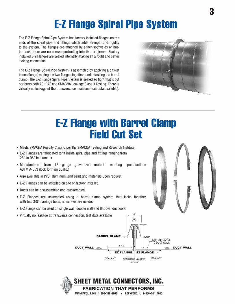
The E-Z Flange Spiral Pipe System has factory installed flanges on the ends of the spiral pipe and fittings which adds strength and rigidity to the system. The flanges are attached by either spotwelds or but-ton lock, there are no screws protruding into the air stream. Factory installed E-Z Flanges are sealed internally making an airtight and better looking connection.
The E-Z Flange Spiral Pipe System is assembled by applying a gasket to one flange, mating the two flanges together, and attaching the barrel clamp. The E-Z Flange Spiral Pipe System is sealed so tight that it out performs both ASHRAE and SMACNA Leakage Class 3 Testing. There is virtually no leakage at the transverse connections (test data available).
• Meets SMACNA Rigidity Class C per the SMACNA Testing and Research Institute.
• E-Z Flanges are fabricated to fit inside spiral pipe and fittings ranging from 26” to 96” in diameter
• Manufactured from 16 gauge galvanized material meeting specifications ASTM A-653 (lock forming quality)
• Also available in PVS, aluminum, and paint grip materials upon request
• E-Z Flanges can be installed on site or factory installed
• Ducts can be disassembled and reassembled
• E-Z Flanges are assembled using a barrel clamp system that locks together with two 3/8” carriage bolts, no screws are needed.
• E-Z Flange can be used on single wall, double wall and flat oval ductwork
• Virtually no leakage at transverse connection, test data available
E-Z Flange with Barrel ClampField Cut Set
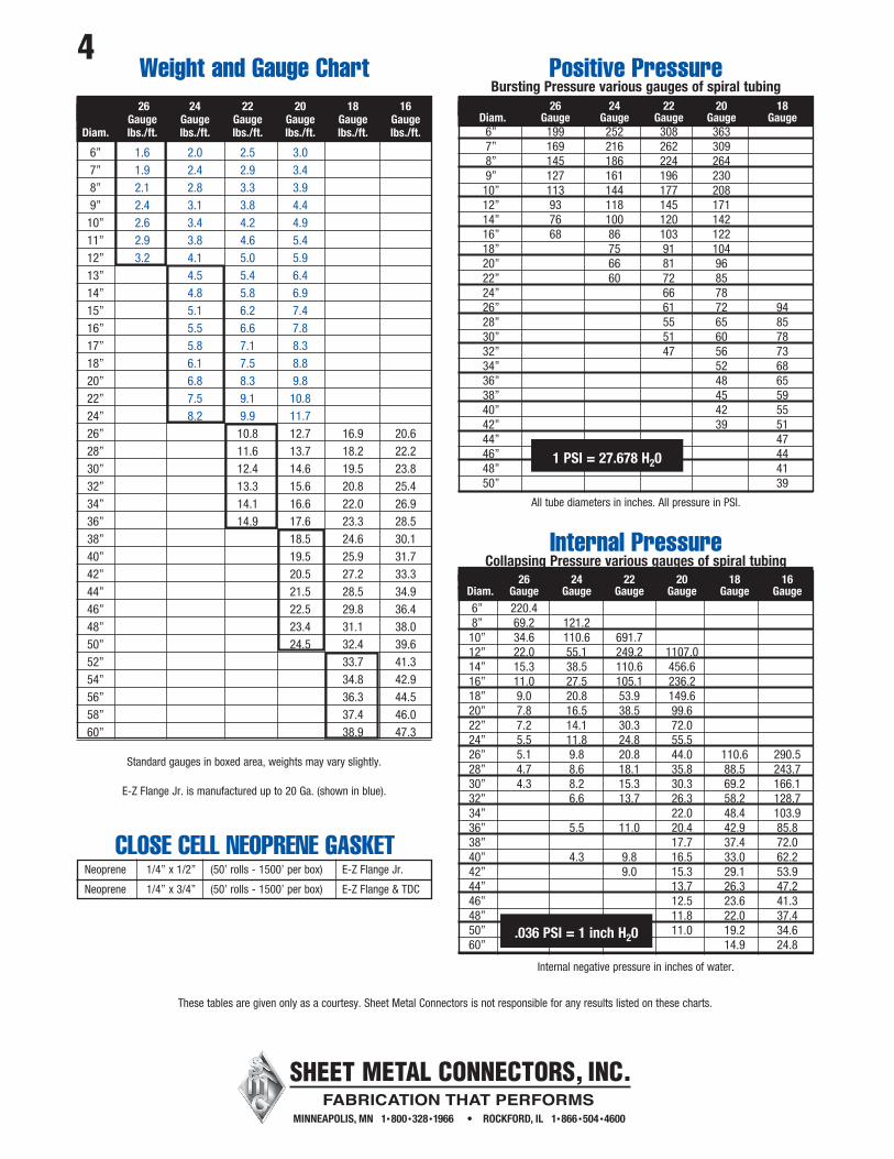
4 26 24 22 20 18 16 Gauge Gauge Gauge Gauge Gauge Gauge Diam. lbs./ft. lbs./ft. lbs./ft. lbs./ft. lbs./ft. lbs./ft.
6” 1.6 2.0 2.5 3.0 7” 1.9 2.4 2.9 3.4 8” 2.1 2.8 3.3 3.9 9” 2.4 3.1 3.8 4.4 10” 2.6 3.4 4.2 4.9 11” 2.9 3.8 4.6 5.4 12” 3.2 4.1 5.0 5.9 13” 4.5 5.4 6.4 14” 4.8 5.8 6.9 15” 5.1 6.2 7.4 16” 5.5 6.6 7.8 17” 5.8 7.1 8.3 18” 6.1 7.5 8.8 20” 6.8 8.3 9.8 22” 7.5 9.1 10.8 24” 8.2 9.9 11.7 26” 10.8 12.7 16.9 20.6 28” 11.6 13.7 18.2 22.2 30” 12.4 14.6 19.5 23.8 32” 13.3 15.6 20.8 25.4 34” 14.1 16.6 22.0 26.9 36” 14.9 17.6 23.3 28.5 38” 18.5 24.6 30.1 40” 19.5 25.9 31.7 42” 20.5 27.2 33.3 44” 21.5 28.5 34.9 46” 22.5 29.8 36.4 48” 23.4 31.1 38.0 50” 24.5 32.4 39.6 52” 33.7 41.3 54” 34.8 42.9 56” 36.3 44.5 58” 37.4 46.0 60” 38.9 47.3
Standard gauges in boxed area, weights may vary slightly.
E-Z Flange Jr. is manufactured up to 20 Ga. (shown in blue).
Weight and Gauge Chart
Internal PressureCollapsing Pressure various gauges of spiral tubing
26 24 22 20 18 16 Diam. Gauge Gauge Gauge Gauge Gauge Gauge 6” 220.4 8” 69.2 121.2 10” 34.6 110.6 691.7 12” 22.0 55.1 249.2 1107.0 14” 15.3 38.5 110.6 456.6 16” 11.0 27.5 105.1 236.2 18” 9.0 20.8 53.9 149.6 20” 7.8 16.5 38.5 99.6 22” 7.2 14.1 30.3 72.0 24” 5.5 11.8 24.8 55.5 26” 5.1 9.8 20.8 44.0 110.6 290.5 28” 4.7 8.6 18.1 35.8 88.5 243.7 30” 4.3 8.2 15.3 30.3 69.2 166.1 32” 6.6 13.7 26.3 58.2 128.7 34” 22.0 48.4 103.9 36” 5.5 11.0 20.4 42.9 85.8 38” 17.7 37.4 72.0 40” 4.3 9.8 16.5 33.0 62.2 42” 9.0 15.3 29.1 53.9 44” 13.7 26.3 47.2 46” 12.5 23.6 41.3 48” 11.8 22.0 37.4 50” 11.0 19.2 34.6 60” 14.9 24.8
.036 PSI = 1 inch H20
Internal negative pressure in inches of water.
26 24 22 20 18 Diam. Gauge Gauge Gauge Gauge Gauge 6” 199 252 308 363 7” 169 216 262 309 8” 145 186 224 264 9” 127 161 196 230 10” 113 144 177 208 12” 93 118 145 171 14” 76 100 120 142 16” 68 86 103 122 18” 75 91 104 20” 66 81 96 22” 60 72 85 24” 66 78 26” 61 72 94 28” 55 65 85 30” 51 60 78 32” 47 56 73 34” 52 68 36” 48 65 38” 45 59 40” 42 55 42” 39 51 44” 47 46” 44 48” 41 50” 39
All tube diameters in inches. All pressure in PSI.
1 PSI = 27.678 H20
Positive PressureBursting Pressure various gauges of spiral tubing
These tables are given only as a courtesy. Sheet Metal Connectors is not responsible for any results listed on these charts.
CLOSE CELL NEOPRENE GASKETNeoprene 1/4” x 1/2” (50’ rolls - 1500’ per box) E-Z Flange Jr.
Neoprene 1/4” x 3/4” (50’ rolls - 1500’ per box) E-Z Flange & TDC

5E-Z Flange Spiral Pipe System
D
D
Adjustable Elbows & Angles
D
D
Adjustable elbows and angles are versatile and are most commonly used in a standard spiral duct system.
Full sweep elbows and angles are available up to 16” diameter
90° Throat and Gauge Chart 26 24 22 Diam. Gauge Gauge Gauge
6” 3” 3” 3” 7” 3” 3” 3” 8” 3” 3” 3” 9” 3” 3” 3” 10” 3” 3” 3” 11” 4” 4 4” 12” 4 1/2” 4 1/2” 4 1/2” 13” 5” 5” 5”
26 24 22 Diam. Gauge Gauge Gauge
14” N/A 4” 4” 15” N/A 4” 4” 16” N/A 4” 4” 18” N/A 5” 5” 20” N/A 6” 6” 22” N/A N/A 6” 24” N/A N/A 6”
45° Throat and Gauge Chart 26 24 22 Diam. Gauge Gauge Gauge
6” 5” 5” 5” 7” 6” 6” 6” 8” 6” 6” 6” 9” 6” 6” 6” 10” 6” 6” 6” 11” 6” 6” 6” 12” 6” 6” 6” 13” 6” 6” 6”
26 24 22 Diam. Gauge Gauge Gauge
14” N/A 6” 6” 15” N/A 6” 6” 16” N/A 6” 6” 18” N/A 6” 6” 20” N/A 8” 8” 22” N/A N/A 9” 24” N/A N/A 10”
Sheet Metal Connectors, Inc. E-Z Flange Spiral Pipe System has a complete line of compatible fittings. E-Z Flange fittings are manufactured on our state of the art fabri-cation equipment. Many different materials, gauges, and configurations are available. E-Z Flange fittings can be fabricated with standing seam, elbow lock seam, or welded seam construction. Please consult our factory for more information.
All fittings are manufactured with:
• E-Z Flange Jr. with Barrel Clamp – 6” to 24” Diameter• E-Z Flange with Barrel Clamp – 26” to 96” Diameter
FittingsElbow Lock Seam
Riveted Lap Seam
Standing Seam
Butt Weld Seam
Stich Weld

6E-Z Flange Spiral Pipe System
Welded Gored Elbows & Angles
Welded Gored Elbows & AnglesWelded Gored elbows and angles are used in high pres-sure and low leakage systems. Standard elbows and angles are fabricated from 20 gauge material. Available in E-Z Flange Jr. 6” – 24” diameter and E-Z Flange 26” – 60” diameter. 52” and larger in diameter 90 degree full sweep (1.5 x CL) elbows are fabricated using two 45 degree angles connected with an E-Z Flange and Barrel Clamp unless otherwise specified.
Full Sweep Standing Seam Elbows8”- 30” will be a 5 gore one piece standard throat construction. 32” and larger in diameter 90 degree full sweep elbows are fabricated using two 45 degree angles connected with an E-Z Flange and Barrel Clamp unless otherwise specified.
Standard Throats
8” thru 18” 8” Throat 20” thru 40” 10” Throat 42” thru 60” * 20” Throat
Standing Seam Elbows & AnglesStanding Seam Elbows and AnglesStanding Seam fittings work well for medium pressure applications plus offer an alternative to welded elbows and angles. Available in E-Z Flange Jr. 8” – 24” diameter and E-Z Flange 26” – 60” diameter.* 42” and larger diameter 90 degree elbows are fabricated using two 45 degree angles connected with an E-Z Flange and Barrel Clamp unless otherwise specified.
D
D
D
90°
R = 1 1/2 x D
D
45°
R = 1 1/2 x D

7E-Z Flange Spiral Pipe System
All stamped fittings are manufactured from extra deep drawing steel (EDDS) in accordance with ASTM–A653. This type of steel is manufactured by domestic steel mills and has some unique qualities. Stamped fittings are precision drawn, tolerances must be within + or - .002 thickness to assure a quality product at all times. All pressed fittings are made of 24 Ga. or 22 Ga. Galvanized material with a G60 coating thickness and are chemically treated to retard white rust.
Two Piece Pressed Solid Welded Elbows
Centerline ThroatRadius Chart Diam. 90° 45°
6” 10 1/2” 10 1/2” 7” 12” 12” 8” 13 1/2” 13 1/2” 9” 15” 15” 10” 16 1/2” 16 1/2” 12” 19 1/2” 19 1/2”
D
90°
CL
D
45°
CL
A B
Length
Pressed Concentric Reducer A B Overall Length 8” 6” 6 1/4” 10” 6” 8” 10” 8” 6 1/4” 12” 8” 8” 12” 10” 6 1/4” 14” 10” 8” 14” 12” 6 1/4” 16” 10” 10 16” 12” 8 16” 14” 6 1/4” 18” 12” 10 18” 14” 8 18” 16” 6 1/4”
Pressed Reducers
All sizes listed are in stock
8E-Z Flange Spiral Pipe System
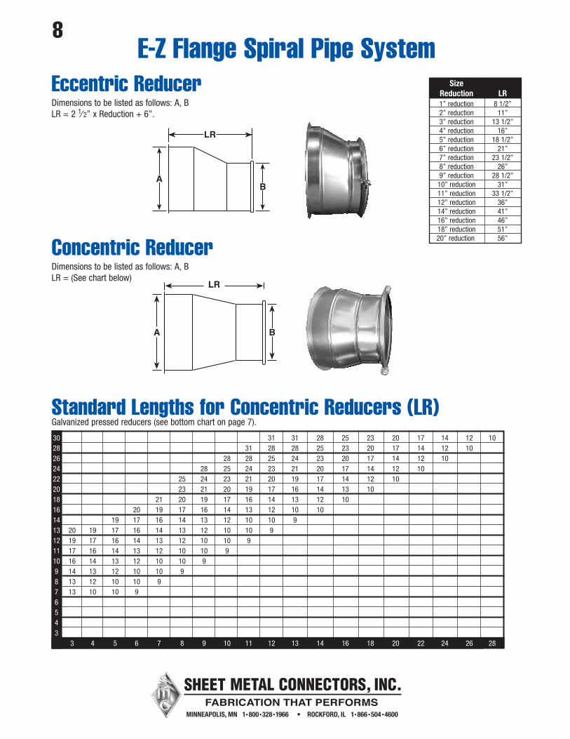
Eccentric Reducer Size Reduction LR 1” reduction 8 1/2” 2” reduction 11” 3” reduction 13 1/2” 4” reduction 16” 5” reduction 18 1/2” 6” reduction 21” 7” reduction 23 1/2” 8” reduction 26” 9” reduction 28 1/2” 10” reduction 31” 11” reduction 33 1/2” 12” reduction 36” 14” reduction 41” 16” reduction 46” 18” reduction 51” 20” reduction 56”
Dimensions to be listed as follows: A, BLR = 2 1⁄ 2” x Reduction + 6”.
Concentric ReducerDimensions to be listed as follows: A, BLR = (See chart below)
A B
LR
30 31 31 28 25 23 20 17 14 12 10 28 31 28 28 25 23 20 17 14 12 10 26 28 28 25 24 23 20 17 14 12 10 24 28 25 24 23 21 20 17 14 12 10 22 25 24 23 21 20 19 17 14 12 10 20 23 21 20 19 17 16 14 13 10 18 21 20 19 17 16 14 13 12 10 16 20 19 17 16 14 13 12 10 10 14 19 17 16 14 13 12 10 10 9 13 20 19 17 16 14 13 12 10 10 9 12 19 17 16 14 13 12 10 10 9 11 17 16 14 13 12 10 10 9 10 16 14 13 12 10 10 9 9 14 13 12 10 10 9 8 13 12 10 10 9 7 13 10 10 9 6 5 4 3 3 4 5 6 7 8 9 10 11 12 13 14 16 18 20 22 24 26 28
Standard Lengths for Concentric Reducers (LR)Galvanized pressed reducers (see bottom chart on page 7).

9E-Z Flange Spiral Pipe System
90° TeeDimensions to be listed as follows: A, B, CL = “C” + 2”
A B
C
L
3"
CrossDimensions to be listed as follows: A, B, C, DL = Largest of “C” or “D” + 2”
A B
C
D
L
3"
3"
Conical TeeDimensions to be listed as follows: A, B, CL = “C” + 7”C+1” = Cone Diameter
L
A B
C
6"
Conical CrossDimensions to be listed as follows: A, B, C, DL = Largest of “C” or “D” + 7”C+1” = Cone Diameter
A B
C
D
L
6"
6"

10E-Z Flange Spiral Pipe System
LateralDimensions to be listed as follows: A, B, CL = (1.414 x C) + 9”
A
C
B
L
7"
3" 6"
Lateral CrossDimensions to be listed as follows: A, B, C, DL = 1.414 x (Larger of “C” or “D”) + 9”
A
C
BL
D
7"
7"
3" 6"
Dimensions to be listed as follows: A, B, C
B
45°
C
A
45°
Pair of Pants (Wye Branch)
Dimensions to be listed as follows: A, O, L
L
A
A
O
Offset

11E-Z Flange Spiral Pipe System
90° Pressed Saddles No DamperDimensions to be listed as follows: A on B
3"
A
B
Existing Pipe
90° Pressed Saddles with Volume DamperDimensions to be listed as follows: A on B Also available with 2” Extension
B
Existing Pipe
6 1/2"
A
90° Pressed Saddles with 2” Stand OffDimensions to be listed as follows: A on B
B
Existing Pipe
A
8 1/2"
A on B
6” on 6”
6” on 8”
6” on 10”
6” on 12”
6” on 14”
8” on 8”
8” on 10”
8” on 12”
8” on 14”
8” on 16”
8” on 18”
10” on 10”
10” on 12”
10” on 14”
10” on 16”
10” on 18”
12” on 12”
12” on 14”
12” on 16”
12” on 18”
Pressed90° Saddles
All sizes listed are in stock.
Other sizes are available.
All pressed fittings are made of 24 Ga. or 22 Ga. Galvanized material with a G60 coatingthickness and is chemically treated to retard white rust.

12E-Z Flange Spiral Pipe System
90° Swedge SaddleDimensions to be listed as follows: A on B
45° Swedge SaddleDimensions to be listed as follows: A on B
90° Full SaddleDimensions to be listed as follows: A on B
45° Full SaddleDimensions to be listed as follows: A on B
Existing Pipe
5/8"
B
3"
A
Existing Pipe
B
5/8"
A
45°
4"
Existing Pipe
B
A
2" 3"
Existing Pipe
B
A
2" 45°
4"

13E-Z Flange Spiral Pipe System
90° Conical Swedge SaddleDimensions to be listed as follows: A on BB = A + 1”
90° Shoe TapDimensions to be listed as follows: A on BC = A + 3”
Register TakeoffsDimensions to be listed as follows: A, B on C(Order Takeoffs by Register Size Only)
Flex Connector
A
B
3"
4"
B
4"
3"
A
C
Existing Pipe
3"
B
A
6"
1"1"
C B
A
6"
1"1"
C
Order as follows: A equals diameter
A
4"
2"

14E-Z Flange Spiral Pipe System
High Efficiency Die Stamped Takeoff(Super Heto)
Patent # US D571,908 S
A Length 5” 10” 6” 5 3/4” 8” 6 1/4” 10” 6 1/4” 12” 6 1/4” 14” 6 1/4”
A Length 6” 5 3/4” 7” 10” 8” 6 1/4” 9” 10 3/4” 10” 6 1/4” 12” 6 1/4” 14” 6 1/4”
A Length 6” 5 3/4” 7” 10” 8” 6 1/4” 9” 10 3/4” 10” 6 1/4” 12” 6 1/4” 14” 6 1/4”
A Length 6” 8” 8” 8 1/2” 10” 8 1/2” 12” 8 1/2” 14” 8 1/2”
Super HetoOrder as follows: A equals diameter
Super Heto w/2” ExtensionOrder as follows: A equals diameter
Super Heto w/ DamperOrder as follows: A equals diameter
Super Heto w/2” StandoffOrder as follows: A equals diameter

15E-Z Flange Spiral Pipe System
E-Z Tap Collars with Volume DamperOrder as follows: A equals diameterAlso available with 2” Insulation Extension
Conical E-Z Tap with Volume DamperOrder as follows: A equals diameterA+2” = Cone DiameterAlso available with 2” Insulation Extension
Hi-Efficiency with Volume DamperOrder as follows: A equals diameterAlso available with 2” Insulation Extension
Overall A Length 6” 4 3/4” 7” 4 3/4” 8” 4 3/4” 9” 4 3/4” 10” 4 3/4” 12” 6 1/2” 14” 6 1/2” 16” 11 1/2” 18” 11 1/2” 20 11 1/2”
Overall A Length 6” 6” 7” 6” 8” 6” 9” 6” 10” 6” 12” 6” 14” 6 1/2” 16” 8 1/4” 18” 8 1/4” 20 8 1/4”
Overall A Length 16” 12 3/4” 18” 12 3/4” 20 12 3/4”
LENGTH
A
CO
NE
DIA
MET
ER

16E-Z Flange Spiral Pipe System
E-Z Tap Collars with 2” StandoffOrder as follows: A equals diameter
Conical E-Z Tap with 2” StandoffOrder as follows: A equals diameterA+2” = Cone Diameter
Hi-Efficiency with 2” StandoffOrder as follows: A equals diameter
Overall A Length 6” 5” 7” 5” 8” 5” 9” 5” 10” 5” 12” 6 1/2” 14” 6 1/2” 16” 11 1/2” 18” 11 1/2” 20” 11 1/2” 22” 14 1/2” 24” 14 1/2”
Overall A Length 6” 8 1/4” 7” 8 1/4” 8” 8 1/4” 9” 8 1/4” 10” 8 1/4” 12” 8 1/4” 14” 8 1/4” 16” 8 1/4” 18” 8 1/4” 20” 8 1/4”
Overall A Length 16” 14 1/4” 18” 15” 20 15”
LENGTH
A
CO
NE
DIA
MET
ER

17E-Z Flange Spiral Pipe System
Double Rod Hanger18” - 60” Diameters, fabricated from 2 7⁄ 8” - 14 gauge galvanized7⁄ 16” Standard Bolt Hole for 3⁄ 8” Rod9⁄ 16” Bolt Hole available on request(Rod and hardware not included)
Single Rod Hangers6” - 16” Diameters, fabricated from 2 7⁄ 8” - 14 gauge galvanized7⁄ 16” Standard Bolt Hole for 3⁄ 8” Rod9⁄ 16” Bolt Hole available on request(Rod and hardware not included)
D
6"
Light Gauge Round Pipe Hangers6” - 36” Diameters, fabricated from 1” - 16 gauge galvanized5⁄ 16” Standard Bolt Hole for 1⁄ 4” Bolt(Bolt not included)
D
1"
Light Gauge Dampers6” - 20” Diameters fabricated from 24 gauge galvanized material1⁄ 4” Rapit Bearing provided with Stiffening beads on 10” diameters and larger
Heavy Volume Dampers6” - 24” 22 gauge, 3⁄ 8” square rod and H.D, Quadrants with stiffener brake26” - 30” 20 gauge, 3⁄ 8” square rod and H.D. Quadrants with stiffener brakeStandoff Quadrants and End Bearings also available
V-Brake
3/8”Square
Rod

Com
pany
Nam
e:
Con
tact
Per
son:
Con
tact
Cel
l #:
PO #
:
Job
Nam
e:
Job
#:
Ship
To:
6” -
24”
E-Z
FLA
NG
E JR
. W/B
AR
REL
CLA
MP
OR
DER
SH
EET
1Fa
x Sh
eet _
____
____
____
of
____
____
____
____
**G
alva
nize
d m
ater
ial u
nles
s ot
herw
ise
note
d**
If an
othe
r mat
eria
l is
need
ed c
ircle
bel
owFA
X76
3-57
2-11
00
*Fie
ld c
ut E
-Z F
lang
e Jr
. w/ B
arre
l Cla
mp
is a
set
that
con
sist
s of
two
slee
ves
w/ 5
/8” f
lang
es a
nd a
con
nect
ing
barre
l cla
mp.
Bar
rel C
lam
p an
d G
aske
t are
aut
omat
ical
ly fi
gure
d in
to o
rder
.
SHEE
T M
ETA
L C
ON
NEC
TOR
S, IN
C.
5850
Mai
n St
. NE
Min
neap
olis
, MN
554
32LO
CAL
LY C
ALL
763-
572-
0000
TOLL
FR
EE 1
-800
-328
-196
6w
ww.
smcd
uct.c
om
6” 8” 10”
12”
14”
16”
18”
20”
22”
24”
Dia
met
er* E
-Z F
lang
eJr
. Set
s9'
-11'
Spi
ral
E-Z
Tap
E-Z
Tap
w/ V
DH
i-Effi
cien
cyTa
keof
fH
ETO
w/ V
DH
ETO
w/ 2
””St
ando
ffE-
Z Ta
pw/
2”” S
OC
onic
alE-
Z Ta
pC
onic
alE-
Z w
/ VD
Con
ical
E-Z
w/ 2
”” SO
6” 8” 10”
12”
14”
16”
18”
20”
22”
24”
Dia
met
er90
˚ Aju
stab
leEl
bow
45˚ A
just
able
Angl
e90
˚ Sta
ndin
gSe
am E
lbow
Tear
Dro
pH
ange
rsIn
sula
ted
Flex
Duc
tFl
ex T
ake
Off
Col
lar
45˚ S
tand
ing
Seam
Ang
le90
˚ Pre
ssed
Elbo
w45
˚ Pre
ssed
Angl
eR
ound
Pip
eH
ange
rsEn
d C
ap(F
lat D
isc)
N/A
N/A
N/A
N/A
N/A
N/A
N/A
N/A
N/A
N/A
N/A
N/A
PVS
PA
INT
GR
IP
A
LUM
INU
M

Com
pany
Nam
e:
Con
tact
Per
son:
Con
tact
Cel
l #:
PO #
:
Job
Nam
e:
Job
#:
Ship
To:
6” -
24”
E-Z
FLA
NG
E JR
. W/B
AR
REL
CLA
MP
OR
DER
SH
EET
2Fa
x Sh
eet _
____
____
____
of
____
____
____
____
**G
alva
nize
d m
ater
ial u
nles
s ot
herw
ise
note
d**
If an
othe
r mat
eria
l is
need
ed c
ircle
bel
owFA
X76
3-57
2-11
00
SHEE
T M
ETA
L C
ON
NEC
TOR
S, IN
C.
5850
Mai
n St
. NE
Min
neap
olis
, MN
554
32LO
CAL
LY C
ALL
763-
572-
0000
TOLL
FR
EE 1
-800
-328
-196
6w
ww.
smcd
uct.c
om
Red
ucer
90˚ S
addl
e45
˚ Sw
edge
Sad
dle
90˚ T
ee45
˚ Lat
eral
Con
ical
90˚
Swed
ge S
addl
e
Qty.
A x
BQ
ty.
A
on B
Qty.
A on
BQ
ty.
A
x C
Qty.
A x
CQ
ty.
A
on B
x x x x x x x
on on on on on on on
x x x x x x x
x x x x x x x
on on on on on on on
on on on on on on on
Gas
ket -
25’
/roll
Qty.
Nut
s &
Bol
ts -
1000
/box
Qty.
18ga
Han
ger -
50#
/bdl
Bdl.
Duc
t Tap
e - 2
” x 6
0yds
Rol
lsFo
il Ta
pe -
2” x
50y
dsR
olls
Tek
Scre
ws
- 100
0/bo
xSi
zeQ
ty.10
x 1
/2”
10 x
3/4
”10
x 1
”
Duc
t Sea
lant
Tube
Gal
lon
Duc
t Tie
s - 2
5/ba
gSi
zeQ
ty.
36”
48”
Zip
Scre
ws
- 100
0/bo
xSi
zeQ
ty.8
x 1/
2”8
x 3/
4”8
x 1”
2” B
rush
esQ
ty.
Jr. V
ice
Grip
sQ
ty.
2 C
one
Diff
user
24”
x 2
4”
Size
Qty.
6” 8” 10”
12”
14”
3 C
one
Diff
user
24”
x 2
4”
Size
Qty.
6” 8” 10”
12”
14”
Egg
Cra
te
Size
Qty.
6” x
2’
1’ x
2’
2’ x
2’
2’ x
4’
Hex
Nut
Driv
eQ
ty.D
uct T
ie T
ensi
onin
g To
olQ
ty.
PVS
PA
INT
GR
IP
A
L�M
IN�
M