exxim.comexxim.com/fidex/documentation-fidex/dghill/fidex user... · web viewthe field light is the...
TRANSCRIPT

hFidex User Manual
Type of Document SpecificationsOperation DescriptionWork InstructionsS/W Version DocumentationTest PlanTest Reportsite ReportItem Selection ReportHazard AnalysisProduction ReleaseTechnical Report User Documentation
Product : Fidex
Document Number : ANI-80-300HFB09-0.5
Document Revision : 0.1
Revision Date : April 15June 8, 2009
Author : Horst Bruning
File Path : Animage\User Manual
Number of pages in document :
Animage LLC Company Confidential

Animage, LLC Document # ANI-80-300HFB09-0.5 FIDEX User Manual
Revision Description
Rev Date Comments Approved by
0.1 April 15, 2009 Document Creation – Horst Bruning0.4 July 8, 2009 Document expanded with CT, Fluoro, DR -
Dave Hill
0.5 July 24, 2009 Glossary, tests with Irene Bruning
Document Revision: 0.5 Animage, LLC Company Confidential Page 2 of 34July 8, 2009

Animage, LLC Document # ANI-80-300HFB09-0.5 FIDEX User Manual
Table of Contents
1 About this Manual............................................................................51.1 CONTENTS.............................................................................................................51.2 STYLISTIC CONVENTIONS..........................................................................................61.3 HOW TO USE THIS MANUAL......................................................................................7
2 Safety Information...........................................................................82.1 PRIMARY SAFETY RULES...........................................................................................82.2 SWITCHING THE SYSTEM OFF....................................................................................82.3 EMERGENCY SHUT-OFF............................................................................................82.4 GUIDELINES FOR OPERATOR AND PATIENT SAFETY........................................................8
2.4.1 Patient Positioning.........................................................................................82.4.2 Radiation Protection.......................................................................................82.4.3 Laser Exposure................................................................................................82.4.4 Computer Connection.....................................................................................8
3 Equipment Safety and Maintenance................................................93.1 INSTALLATION SITE REQUIREMENTS............................................................................93.2 SAFEGUARDS........................................................................................................103.3 SYSTEM MODIFICATIONS........................................................................................113.4 MAINTENANCE AND SERVICE...................................................................................113.5 FOOTSWITCH........................................................................................................133.6 CLEANING AND DISINFECTING..................................................................................13
3.6.1 Agents to avoid............................................................................................133.6.2 Cleaning........................................................................................................14
4 Getting Started..............................................................................154.1 SYSTEM INTRODUCTION.........................................................................................15
5 Daily Check....................................................................................155.1 AIR SCAN.............................................................................................................155.2 PHANTOM CHECK..................................................................................................15
6 Scanning a Patient.........................................................................156.1 ENTERING A NEW PATIENT INTO THE DATA BASE........................................................16
6.1.1 Study............................................................................................................ 166.1.2 Detector configuration.................................................................................17
6.2 PATIENT POSITIONING...........................................................................................177 Performing CR and DR...................................................................18
7.1 CR.....................................................................................................................187.2 DX.....................................................................................................................19
8 DR Visualization.............................................................................198.1 CR.....................................................................................................................208.2 DX.....................................................................................................................20
9 Performing CT................................................................................209.1 HOW DOES CT WORK?..........................................................................................20
Document Revision: 0.5 Animage, LLC Company Confidential Page 3 of 34July 8, 2009

Animage, LLC Document # ANI-80-300HFB09-0.5 FIDEX User Manual
9.2 ANIMAL PREPARATION AND SEDATION......................................................................219.3 CHOOSING SCAN PARAMETERS.................................................................................21
9.3.1 Basic mode...................................................................................................229.3.2 Advanced mode............................................................................................23
9.4 TOTAL SCAN TIME.................................................................................................259.5 LOCALIZATION......................................................................................................259.6 DATA ACQUISITION................................................................................................259.7 RECONSTRUCTION.................................................................................................26
10 CT Visualization..............................................................................2710.1 VOLUME RENDERING.............................................................................................2710.2 SLICE DATA - MPR................................................................................................28
11 Performing Fluoroscopy.................................................................3112 Working with a Study.....................................................................3213 Creating a Report...........................................................................3214 Quality Assurance..........................................................................3215 Appendix........................................................................................32
15.1 GLOSSARY........................................................................................................... 32
Document Revision: 0.5 Animage, LLC Company Confidential Page 4 of 34July 8, 2009

Animage, LLC Document # ANI-80-300HFB09-0.5 FIDEX User Manual
1 About this Manual This manual is distributed for the use of the equipment operator.Animage,LC reserves the right to change the contents of this manual without notice.
The document may not, in whole or in part, be modified, copied, reproduced, distributed, translated, stored or published over networks, web sites or other on-line services, without express permission of Animage,LLC.
FIDEX is a registered trademark of Animage,LLC. All other other product and brand names are trademarks of their respective companies.
FIDEX is manufactured by :
Animage,LLC3825 Hopyard RoadSuite 220Pleasanton, CA 94588UAPhone: +1 925 416 1900Fax: +1 925 369 0385
All rights reserved.
1.1 ContentsThis manual is intended to provide the end user with information and instructions regarding the use of the multiple-modality veterinary x-ray scanner FIDEX. It describes hardware, software, and operation.Prior to operating the scanner, this manual should be read and understood. Please keep this manual and other associated documentation for future reference and for new operators and qualified personnel.
The manual is organized as follows:
Section 1 (About this Manual), provides general information about structure and stylistic conventions of this manual.
Section 2 (Safety Information), includes primary safety information and procedures regarding the use of the scanner. Both operator and patient safety concerns are addressed.
Document Revision: 0.5 Animage, LLC Company Confidential Page 5 of 34July 8, 2009

Animage, LLC Document # ANI-80-300HFB09-0.5 FIDEX User Manual
Section 3 (Equipment Safety and Maintenance), provides more detailed safety information and operating procedures, and maintenance rules for the machine.
Section 4 (Getting Started), contains a general description of the main scanner components and their operation.
Section 5 (Performing checks), illustrates check to be performed by the user on a regular basis.
Section 6 (Entering a New Patient in the Data Base), describes the steps to ensure a patient is properly registered before scanning.
Section 7 (Performing CR), explains user actions necessary to obtain a digital overview radiograph (CR, computed radiography).
Section 8 (Performing CT), explains user actions necessary to obtain a volume CT acquisition.
Section 10 (CT Visualization), illustrates various ways to display the volume data on the screen.
Section 11 (Fluoroscopy), is a description of fluoroscopic imaging with associated safety instructions.
Section 12 (Working with a Study), gives examples of visualization tools to be used in the evaluation of images taken during a study.
Section 13 (Creating a Report), gives a template for a report as the result of a procedure or study.
Section 14 (Quality Assurance), contains the steps to run the FIDEX Quality Assurance process.
Section 15 (Appendix), lists glossary, technical specifications, standards and labeling.
1.2 Stylistic Conventions
Text Format Example MeaningBold Italic Menu or toolbar itemItalic Patient file Window titleBold underlined Apply Button command<text> <report template> Typed textCAPITAL LETTER ENTER Keyboard command
Important safety information and notes are highlighted in this manual as follows:
WARNING:Warn of the presence of a potential hazard, which may cause injury
Document Revision: 0.5 Animage, LLC Company Confidential Page 6 of 34July 8, 2009

Animage, LLC Document # ANI-80-300HFB09-0.5 FIDEX User Manual
CAUTION:Warns of the presence of a potential hazard, which may cause damage to the equipment.
NOTE:Draws attention to important but non-hazardous information.
1.3 How to use this manualThis manual should be read cover to cover. We recommend paying particular attention to the sections on safety and maintenance in section 2, 3 and 9..
Document Revision: 0.5 Animage, LLC Company Confidential Page 7 of 34July 8, 2009

Animage, LLC Document # ANI-80-300HFB09-0.5 FIDEX User Manual
2 Safety InformationThis section includes all operational safety information relevant to the operator. Please familiarize yourself with this section before operating the scanner.
2.1 Primary Safety Rules
2.2 Switching the system OFF
2.3 Emergency Shut-off
2.4 Guidelines for Operator and Patient Safety
2.4.1 Patient Positioning
2.4.2 Radiation Protection
WARNING:FIDEX is designed for veterinary use. Scanning of humans is not permitted. The operator is responsible for proper use of the machine.
CAUTION:It is recommended that all personnel stay behind x-ray barriers during radiation. In some states it is permissible for the operator to hold the animal during a study, in which case proper precautions like lead aprons and gloves should be used. In particular, personnel should be shielded during CT studies.
2.4.3 Laser Exposure
2.4.4 Computer Connection
Document Revision: 0.5 Animage, LLC Company Confidential Page 8 of 34July 8, 2009
Figure 1: Room layout
Animage, LLC Document # ANI-80-300HFB09-0.5 FIDEX User Manual
3 Equipment Safety and MaintenanceThis section includes all equipment and environment safety and maintenance information.The operator is responsible for the correct usage of the device, conforming to the instructions and procedures provided in the manual. In particular, the operator must observe the following:
The scanner can be operated only by authorized personnel with adequate knowledge of the usage, x-ray emission and local laws regulating the use of x-rays.
The device must never be used if any electrical, mechanical or radiological problems appear. It must never be used if it indicates malfunction of signal or emergency devices.
3.1 Installation Site RequirementsThe system must be installed and operated only in rooms designed for imaging use, according to recommendations of a qualified consultant. In particular, access to the scanner must be restricted during operation. Figure 1 shows a suggested room layout, with minimum room size 8 ft x 12 ft.
No exposure to acid, salt, or rain must occur.Operating temperature: 15oC to 350C.Operating humidity: 20% to 80%, non-condensing.
The equipment must be installed on a horizontal floor. If local regulations
Document Revision: 0.5 Animage, LLC Company Confidential Page 9 of 34July 8, 2009
Animage, LLC Document # ANI-80-300HFB09-0.5 FIDEX User Manual
require, the machine must be bolted to the floor to prevent tipping in case of an earthquake.
Power supplied must conform to local standards and regulations. In the US, a standard 115V/15Amp wall outlet is sufficient for the scanner. The computer should be powered from a separate circuit.
WARNING:Do not try to move the device after installation. Shifting the device could result in injury and could compromise the validity of the installation report.The provided wheels should be used only during installation, performed by authorized personnel.
NOTE:The computer must be installed outside the patient area. Only authorized personnel may handle connection cables between computer and scanner.
3.2 SafeguardsThe device is not protected against dripping fluids and spray. No fluids should enter the scanner as this might result in damage to electrical and electronic components, and could be dangerous to the patient, the operator and the environment.
The device safety systems do not reduce the need for safety measures against fire in the working environment.
Electrostatic discharge.Electrostatic discharge may result in damage to components. Flooring should therefore be constructed of anti-static material.
Fire Extinguisher.Use CO2 fire extinguisher only. It should be installed prominently and within easy reach.
Radiation warning light.A Radiation ON light may be installed by the user to display emission status..
Door Interlocks.An interlock switch, preventing radiation when the door is open, may be installed by the user.
Electromagnetic Compatibility.
Document Revision: 0.5 Animage, LLC Company Confidential Page 10 of 34July 8, 2009

Animage, LLC Document # ANI-80-300HFB09-0.5 FIDEX User Manual
For electromagnetic compatibility see APPENDIX “Technical Specifications”.
3.3 System ModificationsModifications or upgrades to the system must comply with all required regulations.
WARNING:Opening the gantry back panel and tempering with the components is prohibited.
Improper and unauthorized modifications or upgrades of the system components (hardware or software) are prohibited as they can lead to improper functioning of the device, resulting in breakdown and/or accident and/or danger for patent, operator and equipment.
DISCLAIMER:The manufacturer is not responsible for safety, reliability and performance of the system if one of the following applies:
Installation, maintenance, modifications, repairs or upgrades are performed by personnel not directly authorized by the manufacturer or distributor.
Replacement parts have not been approved by the manufacturer or distributor. The environmental safety conditions do not reflect the ones described in thi
manual, the regulation requirements or the advice of a qualified consultant. The system is used in a manner other than specified in this manual.
3.4 Maintenance and Service
WARNING:Always switch power off before any maintenance of the device.
CAUTION:There are no user serviceable parts inside the unit. Do not remove the covers.
WARNING:The only user-replaceable parts are the input accessible fuses, located at the rear interface panel. The replaced fuses must conform to the manufacturer’s specifications.
Document Revision: 0.5 Animage, LLC Company Confidential Page 11 of 34July 8, 2009

Animage, LLC Document # ANI-80-300HFB09-0.5 FIDEX User Manual
CAUTION:For continued protection against the risk of fire, replace only with the same type and rating of fuse.
Regular MaintenanceRegular maintenance is required in order to ensure the proper functioning of the device, as well as for safety of the patient, all personnel and third parties.
Maintenance and service of the device must be performed by personnel directly authorized by the manufacturer or distributor. All system components must be checked and, if necessary, replaced by qualified personnel.
WARNING:If the x-ray source is not used for three months or more, the tube must be conditioned as follows:
One pulse every 30 seconds at 120 kV, 15 mA, 0.1s for 10 times.
Cleaning agent hazardsCertain cleaning agents should be avoided due to possible adverse effects on equipment and/or persons (see section 3.6 “Cleaning and Disinfecting”).
Preventive MaintenancePeriodically check the computer/device power and interface cables. Perform cable checks for the computer, monitors, keyboard, mouse according to manufacturer’s instructions. Device components must be installed and used according to provided technical documentation.
Storage of Components and AccessoriesComponents and accessories must be stored carefully.
MalfunctionsIf the system does not work as stated in this manual, or indicated defects, please contact customer service immediately.
Service ContractThe device must be serviced periodically. Please refer to the manufacturer or distributor to arrange for a maintenance contract.
Maintenance Interval Checklist
Document Revision: 0.5 Animage, LLC Company Confidential Page 12 of 34July 8, 2009

Animage, LLC Document # ANI-80-300HFB09-0.5 FIDEX User Manual
The table below specifies time intervals for maintenance checking. For further details, please refer to local distributor.
Person in charge item activity intervalOperator system QA phantom scan
and analysisweekly
Service support Error log Check 12 monthsExternal components
Check for damage or dust
12 months
Emergency stop check 12 monthsElectrical parameters
Check 12 months
Mechanical parameters
Check 12 months
Patient table Motion test, visual check
12 months
3.5 FootswitchRadiographic and fluoroscopic functions can be controlled by a foot switch. Check regularly for damages to the cable.
3.6 Cleaning and Disinfecting
WARNING:Turn off the main power prior to cleaning and disinfecting.
Some ingredients of cleaning agents may be hazardous to your health. Concentration of such products in air should not exceed limits set by local ordinances. Adhere to all manufacturers’ recommendations on the use of these products, and ensure that the room is well ventilated.
3.6.1 Agents to avoid Do not use sprays as they may seep into components, possibly damaging
electrical parts, causing structural changes in various thermoplastics, or forming flammable mixtures of air and solution vapor.
Do not use abrasive fluids or organic solvents such as aldehyde, acetone, gasoline, spot remover or alcohol (except to clean the monitor screen, and aldehyde-based disinfectants for the table surfaces). These substances may degrade components in the system, resulting in improper functioning of the device.
Document Revision: 0.5 Animage, LLC Company Confidential Page 13 of 34July 8, 2009

Animage, LLC Document # ANI-80-300HFB09-0.5 FIDEX User Manual
Avoid agents releasing ammonia by dissipation or decomposition. Ammonia causes corrosion.
Avoid agents containing silicone: this substance can accumulate causing problems with electrical contacts.
3.6.2 Cleaning
3.6.2.1 Gantry and Patient Table The device can be cleaned with a damp cloth, using mild cleaning solution. Moisten the cloth before applying to the device surface.
CAUTION:Never apply cleaning solution directly to the device.
3.6.2.2 Computer and Peripherals To clean the compute and peripherals, follow the manufacturer’s instructions. If no instructions are provided apply the same guidelines as for the scanner and patient table.
The monitors have a sensitive anti-reflective layer. Clean with a soft cloth. Pure alcohol or alcohol with 1/3 or 2/3 distilled water may be used. Do not use cleaning solution.
NOTE:For further information about safety and maintenance please refer to the local distributor.
3.6.2.3 Disinfecting Standard hydrous solutions of aldehyde-based and/or amphenolic surfactant-based disinfectants are recommended for disinfecting gantry and table top surfaces.
3.6.2.4 Sterilization Sterilization is not required for the intended use of the device.
Document Revision: 0.5 Animage, LLC Company Confidential Page 14 of 34July 8, 2009

Figure 2: Data base choice
Animage, LLC Document # ANI-80-300HFB09-0.5 FIDEX User Manual
4 Getting StartedThis section provides an overview of the FIDEX multiple-modality scanner and its main components. It includes basic information of manual control from the gantry/patient as well as an overview of the available software packages.
4.1 System IntroductionFIDEX is a multiple-modality x-ray scanner for companion animals.5 Daily Check5.1 air scan(not implemented yet)5.2 phantom check Take a 15 cm diameter round plastic bottle filled with water (like a 1 gallon bottle with water or juice) and center it at isocenter. Raise or lower the patient table and put the bottle on the patient table centered using the cross hair coming from the gantry facing the patient table. Hold the bottle in place with tape or straps.
Scanning this water bottle is treated like scanning a patient named "Daily Test" with Study "water phantom". Section 6.1 discusses entering and using patient and study. Section 9.3 describes how to CT scan a patient. Choose "Daily Test" as patient, and "water phantom" as study.. Run a medium patient scan at 120 kV (This is a mode with 23 cm FOV.)
After reconstruction, when MPR slice appears (Section 10.2), set the window level to 0 and the window width to 300 and see that the water bottle is centered at a mid-gray with no gross artifacts or non-uniformities.6 Scanning a PatientIn order to scan a patient, one has to go through a number of steps, which are detailed starting in Section 6.1:
1. Enter/find the patient in the Patient Data Base.
2. Enter a new study in the DB (this includes e.g. the body part to be scanned, and the scan mode (DR or CT).
3. Position the patient on the table.4. Select scan parameters
Document Revision: 0.5 Animage, LLC Company Confidential Page 15 of 34July 8, 2009

Figure 3: Data Base Patient entry
Animage, LLC Document # ANI-80-300HFB09-0.5 FIDEX User Manual
5. Scan the patient6. Generate viewable images (read the CR
plate or reconstruct a CT volume)7. View images 8. Generate a Report
6.1 Entering a New Patient into the Data Base
All imaging operations of FIDEX will be archived in the Patient Data Base DB. This provides easy access for evaluation, makes sure that studies do not get lost, and in general supports DICOM conventions.
A new patient with its relevant demographic and owner’s information should be entered before a study is set up. Enter all information your company requires; items preceded by a * are expected by the data base. (Figure 3) Weight is in pounds. After all the entries have been made, select Apply . If the patient is already present in DB, its records may be accessed through the DB and PATIENT buttons.
6.1.1 Study
Document Revision: 0.5 Animage, LLC Company Confidential Page 16 of 34July 8, 2009

Figure 4: Data Base Study entry
Animage, LLC Document # ANI-80-300HFB09-0.5 FIDEX User Manual
Images are stored in the Patient Data Base DB for each patient under STUDY, which could contain CR images, a CT volume, or a fluoroscopy scene. A patient may be associated with several studies, which are kept in chronological sequence.
Select Study (Figure 4). Give a descriptive name to the study and then select Apply.
A scan can only be performed if the patient is registered in the DB, and a STUDY has been set up.
Once in the STUDY pane, choose the type of study from the top (DR (digital radiograph), CT (computed tomography) or FL (fluoroscopy)). Whatever you choose will be
entered into the DB under the study name you had chosen.
6.1.2 Detector configurationFIDEX has two detectors (x-ray receptors): the large, 14” x 17” CR plate, and the smaller CT/FL detector. The CT detector folds into the C-arm when not in use.
6.2 Patient PositioningThis is best done with the x-ray source at 12 o/clock (default gantry position). If the desired scan is a CR, the table should be in the low position, just above the CR plate. If the scan is a CT scan, the table must be in the CT position (50 mm below the isocenter).
The Gantry Control Panel (GCP) has a push button for the field light. A high power LED projects a rectangular field onto the patient, visualizing the radiation field with its collimated edges.
The GCP also contains push buttons for moving the four collimator vanes in case not the full field is needed. Collimating the radiation field as much as possible if recommended in order to reduce exposure to the patient and scatter to the operator.Use the table in/out switch to move the region of interest close to the center cross in the illuminated rectangle.
Document Revision: 0.5 Animage, LLC Company Confidential Page 17 of 34July 8, 2009

Figure 5: CR acquisitionFigure 6: DX advanced mode
Animage, LLC Document # ANI-80-300HFB09-0.5 FIDEX User Manual
7 Performing CR and DR
Fidex offers CR (Computed Radiography) as its way to deliver a large, 14” x 17” radiograph. The receptor is a CR plate positioned on the C-arm opposite of the x-ray source. If the scanner is in CR mode, the plate will sit safely in its plate holder, ready for exposure with the CT detector lowered. If the scanner is in CT mode, the CT detector is raised into position and the CR detector must not be present. Fidex can also do a DX, which is a 5" x 5" (13 cm x 13 cm) radiograph using the CT detector. Fluoroscopy (Section 11) also uses the CT detector.
For both CR and DX, chose the DR tab at the top left. (Need recommendations for mAs, kV)
7.1 CRTo do a CR, after choosing the DR tab, select CR Exposure from the right side of the window (Figure 5). This should cause the CT detector to be lowered. Enter or modify the animal size and body part description as for CT (Section 9.3.1). Put a CR plate in the holder.
The patient table should be still in the up (CT) position. If the CR is to be taken at any angle other than 0° (12 o'clock), then rotate the gantry manually to that angle. If the CR is to be taken at 0°, then lower the patient table to its lowest position, just above the CR plate. Choose the animal thickness at this body part (if not approximately correct) and press ENABLE.
Document Revision: 0.5 Animage, LLC Company Confidential Page 18 of 34July 8, 2009

Animage, LLC Document # ANI-80-300HFB09-0.5 FIDEX User Manual
Select CR acquisition on the large button at the bottom right. The x-ray tube will warm up and then acquire the data.
Remove the CR plate and put it into the CR reader to acquire the data for further use.
7.2 DXTo do a DX, choose DX ACQUISITION from the right side of the DR tab (Error: Reference source not found). The information required is much the same as for CR (Section 7.1) Although the normal gantry position is with the source at 0°, it is possible to manually move the gantry to another angle. For the basic mode using the parameters suggested, click on the large expose button at the bottom right.
Choosing the Advanced mode over the Basic mode allows the user to modify some parameters (Figure 6). Advanced mode allows change of the detector acquisition mode (9.3.2). the kV, mAs and also gantry angle, which will then rotate the gantry to the chosen angle before acquisition. Gantry position, in o'clock units for the position of the source, may be chosen with the down arrow to the side of the position indication. (Do we want o'clock units?)
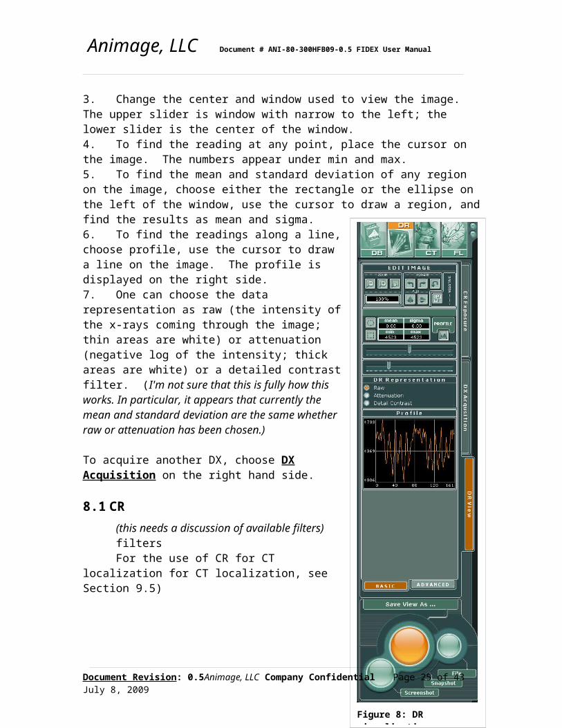
8 DR VisualizationOnce a CR or DX has been acquired, the software will automatically go to the DR view tab on the right hand side. If necessary, the DR view tab can be manually chosen. This tab gives a number of possibilities:1. Change the zoom of the image using one of the three tabs under "Zoom". - makes the image smaller; + makes the image larger, and the third icon shows a rectangle on the image which it then enlarges to fill the screen.2. Change the orientation of the image.3. Change the center and window used to view the image. The upper slider is window with narrow to the left; the lower slider is the center of the window.4. To find the reading at any point, place the cursor on the image. The numbers appear under min and max.5. To find the mean and standard deviation of any region on the image, choose either the rectangle or the ellipse on the left of the window, use the cursor to draw a region, and find the results as mean and sigma.
Document Revision: 0.5 Animage, LLC Company Confidential Page 19 of 34July 8, 2009

Figure 8: DR visualization
Animage, LLC Document # ANI-80-300HFB09-0.5 FIDEX User Manual
6. To find the readings along a line, choose profile, use the cursor to draw a line on the image. The profile is displayed on the right side.7. One can choose the data representation as raw (the intensity of the x-rays coming through the image; thin areas are white) or attenuation (negative log of the intensity; thick areas are white) or a detailed contrast filter. (I'm not sure that this is fully how this works. In particular, it appears that currently the mean and standard deviation are the same whether raw or attenuation has been chosen.)
To acquire another DX, choose DX Acquisition on the right hand side.
8.1 CR(this needs a discussion of available filters)filtersFor the use of CR for CT localization for CT
localization, see Section 9.5)
8.2 DXThe description above is basically for using a DX. I don't know how the CR will differ. For the use of DR for CT localization, see Section 9.5.
9 Performing CT9.1 How does CT work?During CT an x-ray in every direction is acquired and then cross sectional data is reconstructed by untangling the data acquired in each direction. This works well if the subject being scanned does not move while the scan is underway; if the subject moves, then the data is inconsistent and streaks are the likely result. Cone beam CT, as used by Fidex, takes data over a 8 cm long region of the animal at once and reconstructs from that data a volume of cross sections covering 8 cm of the subject. Each element of this volume (voxel) has a numerical value which is proportional to the density of the subject at that point.
Document Revision: 0.5 Animage, LLC Company Confidential Page 20 of 34July 8, 2009
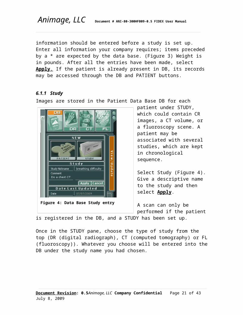
Figure 7: CT basic modeFigure 8: CT scan length options
Animage, LLC Document # ANI-80-300HFB09-0.5 FIDEX User Manual
When the scanner is calibrated, these numbers proportional to the density are called Hounsfield numbers (HU) after Godfrey Hounsfield, Nobel Prize inventor of the CT scanner. Water has number 0 HU, air is -1000 HU, soft tissue ranges from -50 HU to +50 HU, and bone has numbers larger than 500 HU.
9.2 Animal preparation and sedationThe reconstruction algorithm assumes that the subject is always in the same place while the scan is underway. If the subject moves, artifacts such as streaks appear in the images, making interpretation of the images more difficult. Unlike a human, an animal cannot be told to hold its breath during the time of the scan; thus for a good CT the animal should be sedated, intubated if necessary, and strapped to the patient table. The straps may not yet be supplied with the first clinical scanner.
Any metal objects, such as a collar, which will be in the region to be scanned, should also be removed.
Straps are supplied with Fidex; they are arranged so that they can be fastened to the patient table in an area which will not be scanned.
The scanner software gives an estimate of how long the scan chosen will take (scan time in Figure 7), so that you can determine how much sedation is needed.
9.3 Choosing scan parameters
Choose CT scan from the top right hand side on the console. Choose the CT Acquisition tab on the right hand side. CT scans can only be started from the console; because of possible exposure, the technologist should not be standing with the animal for a CT scan.
There are two choices for types of scan mode: "basic" and "advanced".
Document Revision: 0.5 Animage, LLC Company Confidential Page 21 of 34July 8, 2009

Figure 9: CT body part choices
Animage, LLC Document # ANI-80-300HFB09-0.5 FIDEX User Manual
The basic mode (Figure 7) has Animage-recommended scan parameters based on the size and body part of the animal being scanned. The advanced mode gives more flexibility in changing the parameters, but must be used with care. For most purposes, choose "basic".
9.3.1 Basic modeChoose animal size (miniature, small, medium, large (we need weight recommendations here)
Use the drop down arrow to enter the length, which is the distance to be covered in the longitudinal direction (Figure 8) . The scanner covers only 8 cm longitudinally with each rotation; to cover more distance the scanner will automatically move the patient table and add additional rotations. To cover 8 cm no patient table movement is needed; to cover up to 13 cm one movement is need; to cover up to 18 cm 2 movements are needed, etc., up to approximately 60 cm.
Flip the image of the animal head to tail or to the side to indicate how the animal is placed on the patient table. This will be used to label the images with the animal right, left, anterior, posterior.
Move the slider on the image of the body to the body part to be imaged (Figure 9)
The software will display four quantities:kVtotal mAs in the studyfield of view diameter in cm. Figure 7total elapsed time for the scan in seconds.
Select either the standard or high quality mode. The high quality mode uses more x-rays for lower noise but with additional dose.
The field-of-view has been chosen from the body part, animal size, and mode choice. Field of view is the diameter of the scanned field in cm in the transverse direction (in the plane of the scanner's rotation). The scanner has 3 possible fields of view (FOV): 8 cm, 15 cm, 24 cm. Typically the total scan time is smallest for the 8 cm FOV and largest for the 24 cm. The 24 cm FOV requires two rotations of the gantry (clockwise followed by counterclockwise); the other two require only one rotation. Technically, the 8 cm FOV is called full beam, the 15 cm FOV is called half beam, and the 24 cm FOV is called extended mode.
Document Revision: 0.5 Animage, LLC Company Confidential Page 22 of 34July 8, 2009

Figure 10: CT advanced mode
Animage, LLC Document # ANI-80-300HFB09-0.5 FIDEX User Manual
The scan time required is a function of the specific parameters of the chosen modes. Under the "basic" choice, the user does not control these; they are set to give sufficient dose and acquire sufficient data for good images of the body part chosen. For example, a small animal requires less dose than a large one for the same image quality, and the scan time will be shorter.
9.3.2 Advanced modeThe advanced mode (Figure 10) requires that the basic mode be first used to choose animal size, body part , placement and length.
The advanced mode allows the user to change the parameters proposed in the basic mode to something else. The advanced mode gives access to most of the possible parameters affecting image quality, so these parameters are discussed here.
A concept to understand with the advanced mode is that of a projection or frame, which is the data which is acquired at one position of the x-ray source while the gantry rotates. Each projection is essentially a planar x-ray of the animal from a particular direction; for each of these the x-rays are on for 2-10 milliseconds, and the scanner acquires from 30 to 60 projections/second.
The number of frames is the number of views of the subject taken as the scanner rotates through 360°. As each projection has the same kV and mAs, the total dose to the subject rises with the number of projections. The noise in the image is also inversely related to the square root of the amount of x-rays, so more projections mean lower noise in the image. Larger animals require more projections than smaller ones both for dose reasons and to make better images of the parts of the body near the edge of the FOV. However, the total scan time is also increases linearly with the number of projections. The expected values are 256, 357, 512, 745, and 1024.
kV is the maximum potential of the x-rays; Fidex uses both 80 kV and 120 kV. 120 kV is more penetrating, and is necessary for larger animals.
Document Revision: 0.5 Animage, LLC Company Confidential Page 23 of 34July 8, 2009

Animage, LLC Document # ANI-80-300HFB09-0.5 FIDEX User Manual
mAs is the current (mA or milliamperes) used when the x-rays are on and s is the length of the exposure in seconds. kV times mAs is the energy given to the animal, and is thus proportional to the dose.
The tube current is the mA in mAs; it is the current flowing in the x-ray tube.
Exposure time is not displayed; it is the length of time the x-rays are on for each projection (s in mAs) and is the quotient of mAs and mA. Exposure time is usually between 2 and 10 ms.
Quantity of volumes (we need a better name for this) is the number of patient table motions needed to cover the length specified; quantity of volumes is 0 for 8 cm, 1 for 13 cm, etc.
The detector is divided into a matrix of 2048 x 2048 pixels in a 13 cm x 13 cm array. For most CT use, these are averaged into 2x2 or 4x4 pixels. 2x2 averaging gives the highest spatial resolution and is thus appropriate for the smallest animals and lung studies; it also gives 30 projections/second. 4x4 averaging gives sufficient spatial resolution for most studies and gives 60 projections/sec. 1x1 (no averaging) is slower, gives about 7 projections/second, and is almost never used with CT.
These parameters interact with each other and with the characteristics of the detector and x-ray source; thus the software limits the parameter combinations which can be chosen.
The parameter section of the advanced mode is divided into two parts; the input part and the suggested parameters. If you change one of the parameters, the suggested parameter section will give suggested values for other parameters which will meet the restrictions of the scanner. This gives the user the chance to see how these parameters interact; however, the user must enter these suggested values into the parameter choice. If this is not done, the result may well be poor image quality. (Do we need a warning if this is not done?)
Dose is increased by increasing the number of projections, increasing the mAs/projection, and changing the kV from 80 kV to 120 kV. In general, the images are less noisy with higher dose but the scan takes longer. The scanner is prevented from a user choice of parameters which has a significant chance of injuring the animal. The expected values for number of projections are 256,
In the advanced mode it is possible to select a set of parameters and define them as a user-defined mode which then becomes available in the basic mode. (This is not yet implemented.)
Document Revision: 0.5 Animage, LLC Company Confidential Page 24 of 34July 8, 2009
Animage, LLC Document # ANI-80-300HFB09-0.5 FIDEX User Manual
9.4 Total scan timeThe total scan time is dominated by the time for each component scan multiplied by the number of patient longitudinal positions on the animal scanned. For example, a single 512 projection scan using 2x2 binning takes 17 seconds for FOV 8 or 15 cm, and 35 seconds for a 24 cm FOV. Use of 4x4 binning reduces these times to 8 and 17 seconds. The software will estimate the total scan time for you.
9.5 LocalizationThe field light is the primary indicator of position. With the x-ray source in the 12 o'clock position, a button on the gantry control panel turns on the field light. It shows where x-rays will hit the animal in that position once the scan mode has been chosen. For the 8 cm FOV it shows the region which will be scanned. For the 15 cm FOV, it shows half the FOV with the center of the region which will be scanned 1 cm in from the right hand edge. For the 24 cm FOV, it shows a centered 8 cm region. The total region scanned with the 24 cm FOV extends 8 cm more on each side perpendicular to the direction of patient table motion. The FOV's can be moved with the cursor along the direction of couch motion to center on the region of interest. By rotating the gantry to 90°, the region covered on the side of the animal is seen.
If the scanner is equipped with a DR detector, a region to be scanned can be indicated on the DR image. The selection software will indicate the region covered by each of the 3 possible fields of view. After the region has been chosen, the scanner will select the FOV and automatically move the patient table to the correct starting position for the CT scan. (This is my guess as to how this will work; it may be possible to do this also with CR, but the workflow will take longer.)
9.6 Data acquisitionA CT scan is initiated by pressing START on the console (Figure 7) (the large button at the bottom right). The gantry (and patient table if using localization from a DR image) will move to start position, the anode on the x-ray source will begin to rotate, and a beep will occur when the x-rays come on and turn off. During the course of the scan, the gantry and table will move when necessary and the x-rays will turn on and off until the total scan requested is compete. No operator intervention is needed.
During the course of the scan, the console screen will show a selection of the projections as they are acquired.
The scan sequence can be terminated at will by pushing the red emergency stop at the console or by pressing the cancel button on the console. If either of these are done, the
Document Revision: 0.5 Animage, LLC Company Confidential Page 25 of 34July 8, 2009

Animage, LLC Document # ANI-80-300HFB09-0.5 FIDEX User Manual
x-rays turn off and motion stops. As the data is incomplete, it will not be reconstructed. After doing this, the animal will have to be rescanned. (Is this really what we want to have happen?)
When the scan is complete, the beeps and rotation will stop and the console will say "starting reconstruction".
9.7 ReconstructionReconstruction of the volume will take from 30 seconds to several minutes depending upon the volume covered. Once the reconstruction is complete, a volume rendered image of the data will appear on the screen and the image is ready to be visualized, either on the scanner console or on an external work station. Use of this data is discussed in Section 10 following. (Do we need a discussion of number of slices, pixel size, etc. here?)
During reconstruction, partially reconstructed images will appear on the screen. When the reconstruction is complete, slices through the data (MPR, Section 10.2) will appear on the screen.
Document Revision: 0.5 Animage, LLC Company Confidential Page 26 of 34July 8, 2009
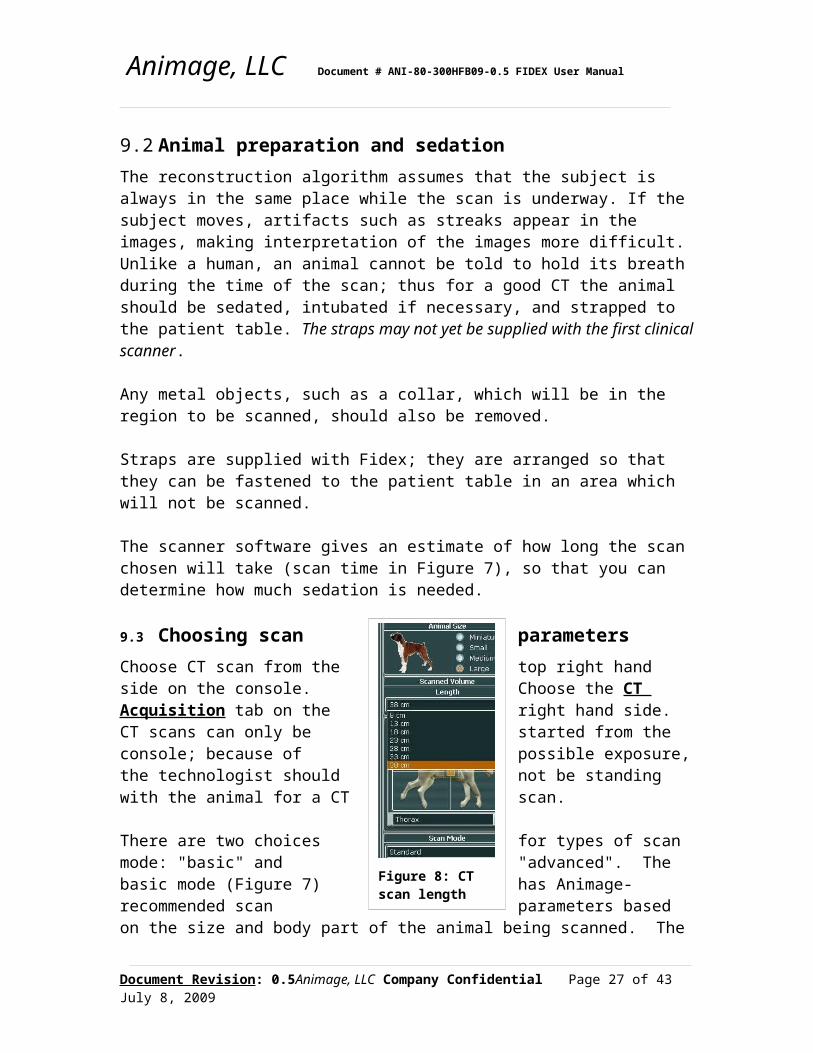
Figure 11: volume rendering with clipping planes
Animage, LLC Document # ANI-80-300HFB09-0.5 FIDEX User Manual
10 CT Visualization10.1 Volume rendering(This needs to be written up)filterscut planes
rotating volumes
Document Revision: 0.5 Animage, LLC Company Confidential Page 27 of 34July 8, 2009

Animage, LLC Document # ANI-80-300HFB09-0.5 FIDEX User Manual
10.2 slice data - MPRCT acquisition acquires a volume of data. MPR (MultiPlanar Reconstruction) shows slices through that data in the transverse, sagittal and coronal planes.
The data itself has been converted to Hounsfield numbers. Hounsfield numbers (HU) are approximately proportional to density and, by convention, water is 0 HU, air is -1000 HU, soft tissue ranges from -50 HU to +50 HU, and bone has numbers larger than 500 HU.
Figure 12 shows the MPR display in slice view. The three primary views are indicated on the left side. The top (outlined in green) is the sagittal view, the center (outlined in blue) is the coronal view, and the bottom (outlined in red) is the transaxial view. The phantom in this figure is a DR resolution phantom lying on the patient table. The enlarged view in the center is selected by clicking on one of the three views on the left; in this case it is a coronal view.
The location in the volume in the views is adjusted by moving the axial lines shown in the left views. For example, moving the red lines in sagittal or transaxial view will change the coronal view and thus the enlarged view.
Window and level are adjusted using the sliders on the bottom, which has low numbers on the left. The window width is changed by varying the end points; the center is changed by moving the rectangular window indicator. The histogram is of number of pixels of a given CT number. Presets for soft tissue and bone will be developed.
Document Revision: 0.5 Animage, LLC Company Confidential Page 28 of 34July 8, 2009

Figure 12: MPR slice view
Figure 19: MPR slab view
Animage, LLC Document # ANI-80-300HFB09-0.5 FIDEX User Manual
Measurements of distance, level, and standard deviation will be developed.
Document Revision: 0.5 Animage, LLC Company Confidential Page 29 of 34July 8, 2009

Figure 13: Fluoroscopy basic modeFigure 14: Fluoroscopy advanced mode
Animage, LLC Document # ANI-80-300HFB09-0.5 FIDEX User Manual
(This figure should be changed to a more anatomic one; this requires also updating the previous text.)
Each element of the volume (voxel) is a cube which has the dimensions on each side chosen in reconstruction. For Fidex, these are usually the same and approximately 0.25 mm. As these slices are very thin, the image is likely to appear extremely noisy in a slice view as in Figure 12. MPR (Figure 19) allows the averaging of slices in one direction to, for example, give a slice width of 2 mm, which would add up 8 voxels in the direction perpendicular to the view seen. Dotted blue lines appear in sagittal and transverse view; the width is adjusted using the cursor. The enlarged image now has much less noise.
11 Performing Fluoroscopy
Fluoroscopy uses the CT detector and can be performed at any gantry angle.
To start fluoroscopy, choose the FL button on the right pane (Figure 13) and then Live Fluoro on
Document Revision: 0.5 Animage, LLC Company Confidential Page 30 of 34July 8, 2009

Animage, LLC Document # ANI-80-300HFB09-0.5 FIDEX User Manual
the right hand side. In the basic mode, choose animal size, part and thickness in the same way as for other studies (Section 9.3.1). Frame rates of 5 fps or 10 fps can be chosen using the down arrow on the right side. Fluoroscopy is set up to last 10 seconds.
The advanced fluoroscopy mode gives additional capability (Figure 14). With it the number of frames/second can be changed up to 30 fps for 2x2 detector averaging and up to 60 fps for 4x4 averaging. To change the length of the fluoroscopy, change the total number of frames. The gantry angle can be changed.
Fluoroscopy studies are then begun either using the foot pedal at the gantry or the large start button at the bottom of the right hand panel. The study ends when the foot pedal is pressed again or the stop button on the panel is used (it doesn't work now; is this what is planned?).
Anyone performing a fluoroscopy study and standing by the animal should be wearing a leather apron and gloves, stand back as far as possible from the animal, and not put his or her hands in the x-ray beam.
To view a fluoroscopy study, choose the Playback tab on the right hand side (It doesn't work now).
12 Working with a StudyIs this meant to be working with Study in general or just a fluoroscopy study?
13 Creating a Report14 Quality Assurance15 Appendix15.1 GlossaryC-Arm
A C-Arm is a C-shaped radiographic device with x-ray source at one end of the C and x-ray detector at the other. It rotates about the center of the C.Collimator
A set of four blades mounted at the x-ray source which adjust the rectaqngular area of exposure to x-rays.CR
Computed Radiography.CR plate
Document Revision: 0.5 Animage, LLC Company Confidential Page 31 of 34July 8, 2009

Animage, LLC Document # ANI-80-300HFB09-0.5 FIDEX User Manual
The detector for CR; typically a 14" x 17" (35 cm x 43 cm) cassette which, after exposure, is converted by a reader into a digital image.CT
Computed Tomography. It acquires an x-ray projection at each angle and uses software to reconstruct a cross section of the scanned object seen by the projections.CT detector
For Fidex, a 13 cm x 13 cm (5.3" x 5.3 ") solid state detector read directly by the Fidex system.DB
The Data Base, which for Fidex contains the descriptions of the animals studied and gives access to all studies performeddetector binning
The DX detector is constructed of 2048 x 2048 detector elements each 0.063 mm in size, giving a total size of 13 cm x 13 cm. The detector elements can be read individually, or binned by the detector system as the average of 2x2 elements (4 elements averaged together) or as the average of 4 x 4 elements (16 elements averaged together). Binning gives less noise and faster reading with a small cost in spatial resolution.DICOM
The Digital Imaging and Communication in Medicine Standard used to view medical images regardless of origin. DICOM is supported by Fidex.DR
Digital Radiography; for Fidex can refer to either a exposure taken as CR or DX with a fixed gantry angle.DX
Digital X-ray; for Fidex DX refers to an exposure taken with the CT detector at a fixed gantry angle.exposure time
The time the x-ray source is on for any projection.Field Light
The light mounted at the x-ray source which shines through the collimation and shows on the patient the area which will be exposed to the x-rays.Field of View
The area at the patient seen by the imaging sequence. This is at isocenter for CT and for DR with gantry not at 0°; it is roughly at patient center for DR at 0°.FOV
Field of View.FL
Fluoroscopy.fluoroscopy
Fluoroscopy is a timed sequence of DX exposures at a given gantry angle. The number of exposures per second is determined by the user and the detector binning
Document Revision: 0.5 Animage, LLC Company Confidential Page 32 of 34July 8, 2009

Animage, LLC Document # ANI-80-300HFB09-0.5 FIDEX User Manual
chosen. Fluoroscopy sequences can then be played back as a movie. Fluoroscopy may be used with contrast medium for angiographic studies or for swallowing or other motion studies.frame
A projection.GCP
Gantry Control Panel; GCP is the set of controls for field light, collimator, and scan mode mounted on the x-ray source end of the gantry.Hounsfield Units
Hounsfield Units are a CT standard for displaying density of CT images. Water is at 0 HU; air at -1000 HU, soft tissue is between -100 HU and 50 HU, and bone is >500 HU. Godfrey Hounsfield received a Nobel Prize for the invention of CT.HU
Hounsfield Units.isocenter
The isocenter is the center of the gantry about which the x-ray source revolves. In the coordinate system of CT images, it is (0,0)kV
Kilovoltage is the potential to which the electrons which cause the x-rays to be created are accelerated; it is also a measure of the maximum energy of the x-rays created. Fidex allows kilovoltages between 50 kV and 120 kV; lower kV tends to give better contrast and higher kV has better penetrating power for larger animals.level
In image display, the number at which the window is centered.localization
Localization is the process of finding where on the patient a CT or an FL is to be performed. An outline of the proposed FOV is placed on a DR image of the patient, adjusted by the user, and when applied the patient table moves to the correct position. Localization only works properly if the patient does not move between DR and the later study.mAs
The mAs is an estimate of the amount of x-rays in a given study. The mA is the x-ray tube current which is multiplied by s, the exposure time. The mAs times the kV is an estimate of the total amount of energy used to create this exposure.MPR
MultiPlanar Reconstruction. MPR is the formation of an arbitrary planar slice through a volume of data by selecting the appropriate voxels from the volume and displaying them as a plane.Patient
The patient is the animal studied. The name "Patient" is also used as the highest level of the data base directory, and is used to find the images associated with that animal.
Document Revision: 0.5 Animage, LLC Company Confidential Page 33 of 34July 8, 2009

Animage, LLC Document # ANI-80-300HFB09-0.5 FIDEX User Manual
pixelA pixel is the smallest element of a two dimensional data set - either of a
radiograph, a detector, or a display screen.projection
A projection is the 2-dimensional data acquired during one x-ray exposure time and is typically at one gantry angle.reconstruction
Reconstruction is the process for CT which takes multiple projections passing through a volume and determines the densities of the individual voxels in the volume studied.Study
"Study" is the next lower level in the DB hierarchy after "Patient"; it contains pointers to the individual CT, DR or FL studies performed.volume rendering
Volume rendering is the display process which allows the user to look at a volume of data, observe surfaces and density differences, cut away portions of the volume, etc.voxel
A voxel is the smallest element of a reconstructed volume data set; it is a 3 dimensional object which is essentially a pixel with thickness.window
In image display, window is the range of number displayed; all pixels whose value is smaller than the lower limit of the window are shown as black; all pixels whose value is larger than the upper limit are shown as white. Pixels with values in between are shown as varying shades of gray depending upon the difference from the limits.
Document Revision: 0.5 Animage, LLC Company Confidential Page 34 of 34July 8, 2009