extrs in intro
DESCRIPTION
ofcTRANSCRIPT


Fig. 3-17: Polarization mode dispersion

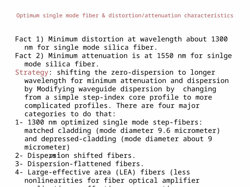
Optimum single mode fiber & distortion/attenuation characteristics
Fact 1) Minimum distortion at wavelength about 1300 nm for single mode silica fiber.
Fact 2) Minimum attenuation is at 1550 nm for sinlge mode silica fiber. Strategy: shifting the zero-dispersion to longer wavelength for minimum
attenuation and dispersion by Modifying waveguide dispersion by changing from a simple step-index core profile to more complicated profiles. There are four major categories to do that:
1- 1300 nm optimized single mode step-fibers: matched cladding (mode diameter 9.6 micrometer) and depressed-cladding (mode diameter about 9 micrometer)
2- Dispersion shifted fibers.3- Dispersion-flattened fibers.4- Large-effective area (LEA) fibers (less nonlinearities for fiber optical
amplifier applications, effective cross section areas are typically greater than 100 ).2m

Optical Fiber communications, 3rd ed.,G.Keiser,McGrawHill, 2000
Single mode fiber dispersion


Dispersion Loss
• As an optical signal travels along the fiber, it becomes increasingly distorted.
• This distortion is a sequence of intermodal and intramodal dispersion.
• Two types:1.Intermodal Dispersion2.Intramodal Dispersion

Intermodal Dispersion:• Pulse broadening due to intermodal dispersion
results from the propagation delay differences between modes within a multimode fiber.
Intramodal Dispersion:• It is the pulse spreading that occurs within a
single mode.– Material Dispersion– Waveguide Dispersion

1) Material Dispersion:• Also known as spectral dispersion or chromatic
dispersion.• Results because of variation due to Refractive
Index of core as a function of wavelength, because of which pulse spreading occurs even when different wavelengths follow the same path.
2) Waveguide Dispersion:• Whenever any optical signal is passed through the
optical fiber, practically 80% of optical power is confined to core & rest 20% optical power into cladding.


Inter Modal Dispersion
• Modal Dispersion– Spreading of a pulse because different modes
(paths) through the fiber take different times– Only happens in multimode fiber– Reduced, but not eliminated, with graded-index
fiber

Chromatic Dispersion
• Different wavelengths travel at different speeds through the fiber
• This spreads a pulse in an effect named chromatic dispersion
• Chromatic dispersion occurs in both singlemode and multimode fiber– Larger effect with LEDs than with lasers– A far smaller effect than modal dispersion

Polarization Mode Dispersion
• Light with different polarization can travel at different speeds, if the fiber is not perfectly symmetric at the atomic level
• This could come from imperfect circular geometry or stress on the cable, and there is no easy way to correct it
• It can affect both singlemode and multimode fiber.


Dispersion
• Different modes take a different amount of timeto arrive at the receiver. Result is a spread-out signal
• Graded Index Fiber– prior discussion concerned with Step Index Fiber– GRIN fiber is designed so that all modes travel at nearly the same speed– GRIN fiber core has a parabolic index of refraction
04/19/2023 15

Dispersion
• Dispersion - spreading of light pulses in a fiber– limits bandwidth– most important types
• Intramodal or chromatic dispersion– material dispersion– waveguide dispersion– profile dispersion
• Intermodal/multimode dispersion• polarization mode dispersion (PMD)
04/19/2023 16

Intramodal or Chromatic Dispersion
Chromatic Dispersion caused by different wavelengths
traveling at different speeds is the result of material
dispersion, waveguide dispersion or profile dispersion
for the fiber characteristics shown at right, chromatic dispersion goes to zero at 1550 nm (Dispersion-Shifted Fiber)
For a light-source with a narrow spectral emission, the bandwidth of the fiber will be very large.(FWHM = Full Width Half Maximum)04/19/2023 17

Material Dispersion, DM
• Material Dispersion - caused by the fact that different wavelengths travel at different speeds through a fiber, even in the same mode.
• Amount of Material Dispersion Determined by:– range of light wavelengths injected into the
fiber (spectral width of source)• LEDs (35 - 170 nm)• Lasers (< 5 nm)
– center operating wavelength of the source• around 850 nm: longer wavelengths (red)
travel faster than shorter wavelengths (blue)• around 1550 nm: the situation is reversed -
zero dispersion occurs where the wavelengths travel the same speed, around 1310 nm
• Material dispersion greatly affects single-mode fibers. In multimode fibers, multimode dispersion usually dominates.04/19/2023 18
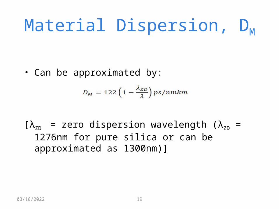
Material Dispersion, DM
• Can be approximated by:
[λZD = zero dispersion wavelength (λZD = 1276nm for pure silica or can be approximated as 1300nm)]
04/19/2023 19

Waveguide (DW) and Profile Dispersion
• Waveguide Dispersion, DW– occurs because optical energy travels in both the core and
cladding at slightly different speeds.– A greater concern for single-mode fibers than for
multimode fibers• Profile Dispersion– the refractive indices of the core and cladding are
described by a refractive index profile– since the refractive index of a graded index fiber varies, it
causes a variation in the propagation of different wavelengths
– profile dispersion is more significant in multimode fibers that in single-mode fibers
04/19/2023 20